EP3192326B1 - Heated coated glazing - Google Patents
Heated coated glazing Download PDFInfo
- Publication number
- EP3192326B1 EP3192326B1 EP15766211.5A EP15766211A EP3192326B1 EP 3192326 B1 EP3192326 B1 EP 3192326B1 EP 15766211 A EP15766211 A EP 15766211A EP 3192326 B1 EP3192326 B1 EP 3192326B1
- Authority
- EP
- European Patent Office
- Prior art keywords
- glazing
- region
- conductive coating
- busbar
- data transmission
- Prior art date
- Legal status (The legal status is an assumption and is not a legal conclusion. Google has not performed a legal analysis and makes no representation as to the accuracy of the status listed.)
- Not-in-force
Links
Images
Classifications
-
- H—ELECTRICITY
- H05—ELECTRIC TECHNIQUES NOT OTHERWISE PROVIDED FOR
- H05B—ELECTRIC HEATING; ELECTRIC LIGHT SOURCES NOT OTHERWISE PROVIDED FOR; CIRCUIT ARRANGEMENTS FOR ELECTRIC LIGHT SOURCES, IN GENERAL
- H05B3/00—Ohmic-resistance heating
- H05B3/84—Heating arrangements specially adapted for transparent or reflecting areas, e.g. for demisting or de-icing windows, mirrors or vehicle windshields
-
- B—PERFORMING OPERATIONS; TRANSPORTING
- B32—LAYERED PRODUCTS
- B32B—LAYERED PRODUCTS, i.e. PRODUCTS BUILT-UP OF STRATA OF FLAT OR NON-FLAT, e.g. CELLULAR OR HONEYCOMB, FORM
- B32B17/00—Layered products essentially comprising sheet glass, or glass, slag, or like fibres
- B32B17/06—Layered products essentially comprising sheet glass, or glass, slag, or like fibres comprising glass as the main or only constituent of a layer, next to another layer of a specific material
- B32B17/10—Layered products essentially comprising sheet glass, or glass, slag, or like fibres comprising glass as the main or only constituent of a layer, next to another layer of a specific material of synthetic resin
- B32B17/10005—Layered products essentially comprising sheet glass, or glass, slag, or like fibres comprising glass as the main or only constituent of a layer, next to another layer of a specific material of synthetic resin laminated safety glass or glazing
- B32B17/10009—Layered products essentially comprising sheet glass, or glass, slag, or like fibres comprising glass as the main or only constituent of a layer, next to another layer of a specific material of synthetic resin laminated safety glass or glazing characterized by the number, the constitution or treatment of glass sheets
- B32B17/10036—Layered products essentially comprising sheet glass, or glass, slag, or like fibres comprising glass as the main or only constituent of a layer, next to another layer of a specific material of synthetic resin laminated safety glass or glazing characterized by the number, the constitution or treatment of glass sheets comprising two outer glass sheets
-
- B—PERFORMING OPERATIONS; TRANSPORTING
- B32—LAYERED PRODUCTS
- B32B—LAYERED PRODUCTS, i.e. PRODUCTS BUILT-UP OF STRATA OF FLAT OR NON-FLAT, e.g. CELLULAR OR HONEYCOMB, FORM
- B32B17/00—Layered products essentially comprising sheet glass, or glass, slag, or like fibres
- B32B17/06—Layered products essentially comprising sheet glass, or glass, slag, or like fibres comprising glass as the main or only constituent of a layer, next to another layer of a specific material
- B32B17/10—Layered products essentially comprising sheet glass, or glass, slag, or like fibres comprising glass as the main or only constituent of a layer, next to another layer of a specific material of synthetic resin
- B32B17/10005—Layered products essentially comprising sheet glass, or glass, slag, or like fibres comprising glass as the main or only constituent of a layer, next to another layer of a specific material of synthetic resin laminated safety glass or glazing
- B32B17/10165—Functional features of the laminated safety glass or glazing
- B32B17/10174—Coatings of a metallic or dielectric material on a constituent layer of glass or polymer
-
- B—PERFORMING OPERATIONS; TRANSPORTING
- B32—LAYERED PRODUCTS
- B32B—LAYERED PRODUCTS, i.e. PRODUCTS BUILT-UP OF STRATA OF FLAT OR NON-FLAT, e.g. CELLULAR OR HONEYCOMB, FORM
- B32B17/00—Layered products essentially comprising sheet glass, or glass, slag, or like fibres
- B32B17/06—Layered products essentially comprising sheet glass, or glass, slag, or like fibres comprising glass as the main or only constituent of a layer, next to another layer of a specific material
- B32B17/10—Layered products essentially comprising sheet glass, or glass, slag, or like fibres comprising glass as the main or only constituent of a layer, next to another layer of a specific material of synthetic resin
- B32B17/10005—Layered products essentially comprising sheet glass, or glass, slag, or like fibres comprising glass as the main or only constituent of a layer, next to another layer of a specific material of synthetic resin laminated safety glass or glazing
- B32B17/10165—Functional features of the laminated safety glass or glazing
- B32B17/10339—Specific parts of the laminated safety glass or glazing being colored or tinted
- B32B17/10348—Specific parts of the laminated safety glass or glazing being colored or tinted comprising an obscuration band
-
- B—PERFORMING OPERATIONS; TRANSPORTING
- B32—LAYERED PRODUCTS
- B32B—LAYERED PRODUCTS, i.e. PRODUCTS BUILT-UP OF STRATA OF FLAT OR NON-FLAT, e.g. CELLULAR OR HONEYCOMB, FORM
- B32B17/00—Layered products essentially comprising sheet glass, or glass, slag, or like fibres
- B32B17/06—Layered products essentially comprising sheet glass, or glass, slag, or like fibres comprising glass as the main or only constituent of a layer, next to another layer of a specific material
- B32B17/10—Layered products essentially comprising sheet glass, or glass, slag, or like fibres comprising glass as the main or only constituent of a layer, next to another layer of a specific material of synthetic resin
- B32B17/10005—Layered products essentially comprising sheet glass, or glass, slag, or like fibres comprising glass as the main or only constituent of a layer, next to another layer of a specific material of synthetic resin laminated safety glass or glazing
- B32B17/1055—Layered products essentially comprising sheet glass, or glass, slag, or like fibres comprising glass as the main or only constituent of a layer, next to another layer of a specific material of synthetic resin laminated safety glass or glazing characterized by the resin layer, i.e. interlayer
- B32B17/10761—Layered products essentially comprising sheet glass, or glass, slag, or like fibres comprising glass as the main or only constituent of a layer, next to another layer of a specific material of synthetic resin laminated safety glass or glazing characterized by the resin layer, i.e. interlayer containing vinyl acetal
-
- H—ELECTRICITY
- H05—ELECTRIC TECHNIQUES NOT OTHERWISE PROVIDED FOR
- H05B—ELECTRIC HEATING; ELECTRIC LIGHT SOURCES NOT OTHERWISE PROVIDED FOR; CIRCUIT ARRANGEMENTS FOR ELECTRIC LIGHT SOURCES, IN GENERAL
- H05B2203/00—Aspects relating to Ohmic resistive heating covered by group H05B3/00
- H05B2203/002—Heaters using a particular layout for the resistive material or resistive elements
- H05B2203/008—Heaters using a particular layout for the resistive material or resistive elements with layout including a portion free of resistive material, e.g. communication window
-
- H—ELECTRICITY
- H05—ELECTRIC TECHNIQUES NOT OTHERWISE PROVIDED FOR
- H05B—ELECTRIC HEATING; ELECTRIC LIGHT SOURCES NOT OTHERWISE PROVIDED FOR; CIRCUIT ARRANGEMENTS FOR ELECTRIC LIGHT SOURCES, IN GENERAL
- H05B2203/00—Aspects relating to Ohmic resistive heating covered by group H05B3/00
- H05B2203/013—Heaters using resistive films or coatings
Definitions
- the invention is concerned with a glazing comprising a conductive coating and a data transmission window.
- a known problem is that such a conductive coating may block electromagnetic radiation in a frequency band needed by transmitters or receivers in a vehicle, i.e. the conductive coating is also a non-transmitting coating.
- a known solution is to provide a 'data transmission window' in the non-transmitting coating for a data signal. Data transmission windows are at least partly non-conductive, so that radiation of a desired frequency band may pass through. Multiple data transmission windows may be required in a windscreen of a vehicle having multiple transmitters or receivers. Examples of transmitters or receivers are cameras, rain sensors and automatic toll payment transponders.
- Busbars are provided for supplying electrical power to an electrically heated region of the conductive coating. Perturbation of heating around a data transmission window, due to its position relative to a busbar or to another window, may result in "hotspots". Hotspots may be defined as unacceptable due to exceeding a temperature threshold or temperature difference threshold.
- EP1274597B1 (Glaverbel/Degand) discloses an automotive windscreen comprising an electrically heatable coating and at least two data transmission windows, at least partially in contact with the electrically heatable coating. In order to minimise hotspots, the two data transmission windows are separated by a portion which is also in contact with the electrically heatable coating.
- EP1274597B1 further discloses that perturbation of heating is greatest when a data transmission window is substantially surrounded by the electrically heatable coating. To improve heating characteristics, it is believed that the two data transmission windows should be spaced from busbars by at least 150 mm and from each other by at least 40 mm. Thus an arrangement of data transmission windows to minimise hotspots according to EP1274597B1 may constrain a position of a receiver or a transmitter.
- US2012/103961 discloses another automotive windscreen comprising an electrically heatable coating according to the prior art.
- a glazing comprising the features set out in claim 1 attached hereto.
- the present invention provides at least one data transmission window separated from an electrically heated region of a conductive coating by a deletion line. Surprisingly, the inventors have found that unacceptable hotspots may be eliminated if a deletion line is arranged between a data transmission window and an electrically heated region of a conductive coating.
- the inventors have found that forming a cut edge of a conductive coating and carrier film according to the prior art (in which a data transmission window is positioned at least partially in contact with the electrically heated region) using a blade causes cracks to propagate diagonally, at approximately 45 degrees to the cut edge.
- the cracks cause electrical discontinuities in the conductive coating, which result in unacceptable hotspots in the electrically heated region and in-service failure of a glazing.
- the inventors have found that forming a deletion line in the conductive coating (leaving the carrier film intact) according to the invention causes fewer cracks in an electrically heated region than in the prior art.
- the deletion line is provided by laser ablation, which provides a smooth cut edge, so cracks are almost completely eliminated.
- hotspots and in-service failures are significantly reduced compared with the prior art.
- At least two data transmission windows are separated by a deletion line from an electrically heated region of a conductive coating which substantially surrounds them, thus providing an unheated region of the conductive coating.
- the inventors have found that hotspots around at least two data transmission windows are reduced by positioning the data transmission windows in an unheated region of the conductive coating.
- prior art discloses data transmission windows which are at least partially in contact with the electrically heated coating.
- the second region is electrically isolated from the second busbar.
- the deletion line is preferably narrow, so as to be invisible to a driver. To the extent that the deletion line is visible to the driver, it serves the visual function of a picture frame around the data transmission windows, so is unobtrusive to the driver.
- the deletion line width is 100 ⁇ m or less.
- the deletion line width is 10 ⁇ m or less.
- the deletion line is a laser ablation line.
- each data transmission window is at least 40 mm wide and at least 20 mm in height.
- the first busbar extends substantially parallel with, and adjacent to, a portion of an upper edge of the glazing.
- the glazing further comprises an auxiliary busbar separated from the first busbar by the deletion line.
- the first busbar and the deletion line are arranged to contact each other, so that a corner of the electrically heated region is formed.
- the corner of the electrically heated region formed by the first busbar and the deletion line is substantially a right angle.
- the inventors have found that unacceptable hotspots can be eliminated when the first busbar and the deletion line are substantially perpendicular at a point of contact with each other.
- the conductive coating has sheet resistance in the range 2 ohms per square to 20 ohms per square.
- the glazing further comprises a carrier film for carrying the conductive coating.
- the carrier film material is polyethylene terephthalate (PET).
- the glazing further comprises first and second sheets of interlayer material, wherein the carrier film is laid over the first sheet of interlayer material and wherein the second sheet of interlayer material is laid over the carrier film.
- the interlayer material is polyvinylbutyral (PVB).
- an automotive vehicle comprising the features set out in claim 13 attached hereto.
- an automotive vehicle comprising a glazing according to the invention and at least two data transmission windows has reduced hotspots compared with a glazing of the prior art.
- a process for manufacture of a glazing comprising the steps set out in claim 14 attached hereto.
- Fig. 1 shows a glazing 1, according to the invention, comprising a conductive coating 10 extending over a substantial portion of the glazing.
- a deletion line 20 is provided to define first and second regions 10a, 10b of the conductive coating 10.
- the deletion line 20 is typically narrow, so as to be invisible for a driver when the glazing 1 is installed in a vehicle.
- a deletion line width should be 100 ⁇ m or narrower.
- First and second busbars 11, 12 are provided in the first region 10a for supplying electrical power to an electrically heated region 10c of the conductive coating 10.
- first busbar 11 is adjacent to an upper edge of the glazing 10 and the second busbar 12 is adjacent to a lower edge of the glazing 1.
- a data transmission window 30 is provided in the second region 10b of the conductive coating 10 at a position suitable for one or more transmitters or receivers. Typically a data transmission window 30 is adjacent an upper edge of the glazing 1.
- the data transmission window 30 is in a portion of the glazing 1 in which the conductive coating 10 is at least partly absent.
- the conductive coating may be removed by any deletion method, such as laser ablation or scratching.
- the conductive coating 10 may be on a carrier film, such as a thin sheet of polyethylene terephthalate (PET).
- the carrier film is typically laid over a first sheet of interlayer material, such as polyvinylbutyral (PVB).
- First and second busbars 11, 12 are arranged in contact with the electrically heated region 10c of the conductive coating 10.
- the carrier film and the first sheet of interlayer material are arranged on a first sheet of glass.
- a second sheet of interlayer material is laid over the carrier film, so that the carrier film is arranged between the first and second sheets of interlayer material.
- a second sheet of glass is laid over the first and second busbars 11, 12.
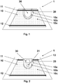
- Fig. 2 shows an embodiment of the invention, in which a glazing 1 comprises a conductive coating 10 and first and second busbars 11, 12. Two data transmission windows 30, 31 are provided in a second region 10b of the conductive coating 10. The second region 10b is separated from the first region 10a by a deletion line 20. Second region 10b is unheated, because it is electrically isolated from the second busbar 12. Second region 10b may be in contact with first busbar 11.
- a length of the first busbar 11 is limited, so as to provide electrical power to only a portion of the electrically heated region 10c, bounded by the deletion line 20.
- An auxiliary busbar 13 is provided, separated from the first busbar 11 by the deletion line 20, for supplying electrical power to another portion of the electrically heated region 10c.
- the auxiliary busbar 13 and the first busbar 11 are electrically connected by a wire external to the glazing.
- First and second data transmission windows 30, 31 may be of any shape and size, for example circular, trapezoidal, rectangular with rounded corners or U-shaped.
- the deletion line 20 may define the second region 10b to have any shape.
- the deletion line 20 may circumscribe the second region 10b.
- the second region 10b may extend between the deletion line 20 and an edge of the conductive coating 10.
- a glazing was prepared according to the invention, in which a deletion line defined a second region of a conductive coating, and comprising a data transmission window in the second region.
- a comparative example was prepared having similar features but without a deletion line between the data transmission window and an electrically heated region.
- a conductive coating 10 was provided on a carrier film comprising a sheet of PET.
- Surface resistivity of the conductive coating 10 on the carrier film was between 2 and 20 ohms per square.
- the sheet of PET was laid over a first sheet of interlayer material (PVB) in a manner known in the art.
- a first busbar 11 and an auxiliary busbar 13 were arranged on an electrically heated region 10c of the conductive coating 10 on the sheet of PET.
- the first sheet of PVB and the sheet of PET were laid over the first sheet of glass.
- the sheet of PET was cut back from an edge of the first sheet of glass, in a manner known in the art to avoid corrosion at the edge of a laminated glazing.
- a second sheet of interlayer material (PVB) was laid over the carrier film so that the carrier film was between the two sheets of PVB.
- a second sheet of glass was laid on top of the second sheet of PVB to form an assembly.
- the assembly was pressed at its edges and degassed, then subjected to elevated temperature and elevated pressure in an autoclave according to a process known in the art to form a laminated glazing 1.
- An electrical power supply was connected to the laminated glazing 1 by means of external wires, serving as electrodes.
- a positive electrode was connected to the first busbar 11, in parallel with the auxiliary busbar 13, and a negative electrode was connected to the second busbar 12.
- the laminated glazing 1 was thus electrically heated for a predetermined period. At the end of the predetermined period a temperature distribution was measured. The predetermined period was 12 minutes and a measurement apparatus was a thermal imaging camera.
Landscapes
- Surface Heating Bodies (AREA)
- Joining Of Glass To Other Materials (AREA)
- Specific Sealing Or Ventilating Devices For Doors And Windows (AREA)
- Fittings On The Vehicle Exterior For Carrying Loads, And Devices For Holding Or Mounting Articles (AREA)
Description
- The invention is concerned with a glazing comprising a conductive coating and a data transmission window.
- It is known in the field of automotive windscreens to provide a conductive coating suitable for electrical heating of a windscreen. A known problem is that such a conductive coating may block electromagnetic radiation in a frequency band needed by transmitters or receivers in a vehicle, i.e. the conductive coating is also a non-transmitting coating. A known solution is to provide a 'data transmission window' in the non-transmitting coating for a data signal. Data transmission windows are at least partly non-conductive, so that radiation of a desired frequency band may pass through. Multiple data transmission windows may be required in a windscreen of a vehicle having multiple transmitters or receivers. Examples of transmitters or receivers are cameras, rain sensors and automatic toll payment transponders.
- Busbars are provided for supplying electrical power to an electrically heated region of the conductive coating. Perturbation of heating around a data transmission window, due to its position relative to a busbar or to another window, may result in "hotspots". Hotspots may be defined as unacceptable due to exceeding a temperature threshold or temperature difference threshold.
-
EP1274597B1 (Glaverbel/Degand) discloses an automotive windscreen comprising an electrically heatable coating and at least two data transmission windows, at least partially in contact with the electrically heatable coating. In order to minimise hotspots, the two data transmission windows are separated by a portion which is also in contact with the electrically heatable coating. -
EP1274597B1 further discloses that perturbation of heating is greatest when a data transmission window is substantially surrounded by the electrically heatable coating. To improve heating characteristics, it is believed that the two data transmission windows should be spaced from busbars by at least 150 mm and from each other by at least 40 mm. Thus an arrangement of data transmission windows to minimise hotspots according toEP1274597B1 may constrain a position of a receiver or a transmitter.US2012/103961 discloses another automotive windscreen comprising an electrically heatable coating according to the prior art. - There remains a need for an alternative glazing comprising a conductive coating and at least one data transmission window, in order to reduce hotspots whilst permitting adequate freedom of position for transmitters or receivers.
- According to the present invention from a first aspect, a glazing is provided comprising the features set out in
claim 1 attached hereto. - The present invention provides at least one data transmission window separated from an electrically heated region of a conductive coating by a deletion line. Surprisingly, the inventors have found that unacceptable hotspots may be eliminated if a deletion line is arranged between a data transmission window and an electrically heated region of a conductive coating.
- The inventors have found that forming a cut edge of a conductive coating and carrier film according to the prior art (in which a data transmission window is positioned at least partially in contact with the electrically heated region) using a blade causes cracks to propagate diagonally, at approximately 45 degrees to the cut edge. The cracks cause electrical discontinuities in the conductive coating, which result in unacceptable hotspots in the electrically heated region and in-service failure of a glazing. Surprisingly, the inventors have found that forming a deletion line in the conductive coating (leaving the carrier film intact) according to the invention causes fewer cracks in an electrically heated region than in the prior art.
- In an advantageous embodiment, the deletion line is provided by laser ablation, which provides a smooth cut edge, so cracks are almost completely eliminated. Thus hotspots and in-service failures are significantly reduced compared with the prior art.
- According to the present invention, at least two data transmission windows are separated by a deletion line from an electrically heated region of a conductive coating which substantially surrounds them, thus providing an unheated region of the conductive coating. The inventors have found that hotspots around at least two data transmission windows are reduced by positioning the data transmission windows in an unheated region of the conductive coating. By contrast, prior art discloses data transmission windows which are at least partially in contact with the electrically heated coating.
- The second region is electrically isolated from the second busbar.
- The deletion line is preferably narrow, so as to be invisible to a driver. To the extent that the deletion line is visible to the driver, it serves the visual function of a picture frame around the data transmission windows, so is unobtrusive to the driver.
- Preferably, the deletion line width is 100 µm or less.
- Preferably, the deletion line width is 10 µm or less.
- Preferably, the deletion line is a laser ablation line.
- Preferably, each data transmission window is at least 40 mm wide and at least 20 mm in height.
- Preferably, the first busbar extends substantially parallel with, and adjacent to, a portion of an upper edge of the glazing.
- Preferably, the glazing further comprises an auxiliary busbar separated from the first busbar by the deletion line.
- Preferably, the first busbar and the deletion line are arranged to contact each other, so that a corner of the electrically heated region is formed.
- In an advantageous embodiment, the corner of the electrically heated region formed by the first busbar and the deletion line is substantially a right angle. The inventors have found that unacceptable hotspots can be eliminated when the first busbar and the deletion line are substantially perpendicular at a point of contact with each other.
- Preferably, the conductive coating has sheet resistance in the range 2 ohms per square to 20 ohms per square.
- Preferably, the glazing further comprises a carrier film for carrying the conductive coating. More preferably the carrier film material is polyethylene terephthalate (PET).
- Preferably, the glazing further comprises first and second sheets of interlayer material, wherein the carrier film is laid over the first sheet of interlayer material and wherein the second sheet of interlayer material is laid over the carrier film. More preferably the interlayer material is polyvinylbutyral (PVB).
- According to the present invention from a second aspect, an automotive vehicle is provided, comprising the features set out in
claim 13 attached hereto. - Surprisingly, the inventors have found that an automotive vehicle comprising a glazing according to the invention and at least two data transmission windows has reduced hotspots compared with a glazing of the prior art.
- According to the present invention from a third aspect, a process for manufacture of a glazing is provided, comprising the steps set out in claim 14 attached hereto.
- Surprisingly, the inventors have found that a process for manufacture of a glazing according to the invention wherein a deletion line is made by laser ablation has reduced hotspots compared with a glazing of the prior art.
- The invention will now be described by means of non-limiting examples with reference to the attached figures.
-
Fig. 1 shows a glazing according to the invention comprising one data transmission window. -
Fig. 2 shows a glazing according to the invention comprising two data transmission windows. - Although the invention is described herein with particular reference to an automotive windscreen, it will be understood that it has applications to other vehicle glazing, for example a rear window or a side window.
-
Fig. 1 shows aglazing 1, according to the invention, comprising aconductive coating 10 extending over a substantial portion of the glazing. - A
deletion line 20 is provided to define first andsecond regions conductive coating 10. Thedeletion line 20 is typically narrow, so as to be invisible for a driver when theglazing 1 is installed in a vehicle. For a typical windscreen installation, a deletion line width should be 100 µm or narrower. - First and
second busbars first region 10a for supplying electrical power to an electrically heatedregion 10c of theconductive coating 10. Typically thefirst busbar 11 is adjacent to an upper edge of theglazing 10 and thesecond busbar 12 is adjacent to a lower edge of theglazing 1. - A
data transmission window 30 is provided in thesecond region 10b of theconductive coating 10 at a position suitable for one or more transmitters or receivers. Typically adata transmission window 30 is adjacent an upper edge of theglazing 1. - The
data transmission window 30 is in a portion of theglazing 1 in which theconductive coating 10 is at least partly absent. The conductive coating may be removed by any deletion method, such as laser ablation or scratching. - The
conductive coating 10 may be on a carrier film, such as a thin sheet of polyethylene terephthalate (PET). The carrier film is typically laid over a first sheet of interlayer material, such as polyvinylbutyral (PVB). First andsecond busbars heated region 10c of theconductive coating 10. The carrier film and the first sheet of interlayer material are arranged on a first sheet of glass. A second sheet of interlayer material is laid over the carrier film, so that the carrier film is arranged between the first and second sheets of interlayer material. A second sheet of glass is laid over the first andsecond busbars -
Fig. 2 shows an embodiment of the invention, in which aglazing 1 comprises aconductive coating 10 and first andsecond busbars data transmission windows second region 10b of theconductive coating 10. Thesecond region 10b is separated from thefirst region 10a by adeletion line 20.Second region 10b is unheated, because it is electrically isolated from thesecond busbar 12.Second region 10b may be in contact withfirst busbar 11. - In the embodiment of
Fig.2 , a length of thefirst busbar 11 is limited, so as to provide electrical power to only a portion of the electricallyheated region 10c, bounded by thedeletion line 20. Anauxiliary busbar 13 is provided, separated from thefirst busbar 11 by thedeletion line 20, for supplying electrical power to another portion of the electricallyheated region 10c. Typically theauxiliary busbar 13 and thefirst busbar 11 are electrically connected by a wire external to the glazing. - First and second
data transmission windows - The
deletion line 20 may define thesecond region 10b to have any shape. - The
deletion line 20 may circumscribe thesecond region 10b. - The
second region 10b may extend between thedeletion line 20 and an edge of theconductive coating 10. - A glazing was prepared according to the invention, in which a deletion line defined a second region of a conductive coating, and comprising a data transmission window in the second region. A comparative example was prepared having similar features but without a deletion line between the data transmission window and an electrically heated region.
- In both the example and the comparative example, a
conductive coating 10 was provided on a carrier film comprising a sheet of PET. Surface resistivity of theconductive coating 10 on the carrier film was between 2 and 20 ohms per square. The sheet of PET was laid over a first sheet of interlayer material (PVB) in a manner known in the art. - A
first busbar 11 and anauxiliary busbar 13 were arranged on an electricallyheated region 10c of theconductive coating 10 on the sheet of PET. The first sheet of PVB and the sheet of PET were laid over the first sheet of glass. - The sheet of PET was cut back from an edge of the first sheet of glass, in a manner known in the art to avoid corrosion at the edge of a laminated glazing. The cut-back edge of the sheet of PET and a ceramic print, known as an obscuration band, printed on surface 2 (inner surface) of the first sheet of glass, were arranged so that the cut-back edge was hidden by the obscuration band.
- A second sheet of interlayer material (PVB) was laid over the carrier film so that the carrier film was between the two sheets of PVB. A second sheet of glass was laid on top of the second sheet of PVB to form an assembly. The assembly was pressed at its edges and degassed, then subjected to elevated temperature and elevated pressure in an autoclave according to a process known in the art to form a
laminated glazing 1. - An electrical power supply was connected to the
laminated glazing 1 by means of external wires, serving as electrodes. A positive electrode was connected to thefirst busbar 11, in parallel with theauxiliary busbar 13, and a negative electrode was connected to thesecond busbar 12. Thelaminated glazing 1 was thus electrically heated for a predetermined period. At the end of the predetermined period a temperature distribution was measured. The predetermined period was 12 minutes and a measurement apparatus was a thermal imaging camera. - In the comparative example, hotspots were observed exceeding 95 degrees C, which is defined as a threshold of unacceptable temperature. By contrast, in the example according to the invention no unacceptable hotspots were observed.
Claims (14)
- A glazing (1), comprising:- a conductive coating (10) suitable for electrical heating- a deletion line (20) defining first and second regions (10a, 10b) of the conductive coating (10)wherein the first region (10a) comprises:- an electrically heated region (10c)- first and second busbars (11, 12) for supplying electrical power to the electrically heated region (10c)wherein the second region (10b) comprises at least one data transmission window (30)
characterised in that:- the second region (10b) is electrically isolated from the second busbar (12). - A glazing according to any preceding claim, comprising a second data transmission window (31).
- A glazing according to any preceding claim, wherein the deletion line (20) width is 100 µm or less.
- A glazing according to any preceding claim, wherein the deletion line (20) width is 10 µm or less.
- A glazing according to any preceding claim, wherein the deletion line (20) is a laser ablation line.
- A glazing according to any preceding claim, wherein each data transmission window is at least 40 mm wide and at least 20 mm in height.
- A glazing according to any preceding claim, wherein the first busbar (11) extends substantially parallel with and adjacent to a portion of an upper edge of the glazing (1).
- A glazing according to any preceding claim, further comprising an auxiliary busbar (13) separated from the first busbar (11) by the deletion line (20).
- A glazing according to any preceding claim, wherein the first busbar (11) and the deletion line (20) are arranged to contact each other, so that a corner of the electrically heated region (10c) is formed.
- A glazing according to any preceding claim, wherein the conductive coating (10) has sheet resistance in the range 2 ohms per square to 20 ohms per square.
- A glazing according to any preceding claim, further comprising a carrier film for carrying the conductive coating (10).
- A glazing according to any preceding claim, further comprising first and second sheets of interlayer material, wherein the carrier film is laid over the first sheet of interlayer material and wherein the second sheet of interlayer material is laid over the carrier film.
- An automotive vehicle having a glazing (1) according to any preceding claim, wherein the interior of the vehicle is provided with at least one transmitter or receiver arranged to transmit or receive an electromagnetic data signal through at least one of the data transmission windows (30, 31).
- A process for manufacture of a glazing (1) comprising the steps:- providing a conductive coating (10) suitable for electrical heating- ablating a deletion line (20) by means of a laser, so as to define first and second regions (10a, 10b) of the conductive coating (10)- providing in the first region (10a) an electrically heated region (10c) by laying down first and second busbars (11, 12) for supplying electrical power to the electrically heated region (10c)- providing in the second region (10b) at least one data transmission window (30)characterised by:- the second region (10b) is electrically isolated from the second busbar (12).
Applications Claiming Priority (2)
| Application Number | Priority Date | Filing Date | Title |
|---|---|---|---|
| GBGB1416175.6A GB201416175D0 (en) | 2014-09-12 | 2014-09-12 | Heated coated glazing |
| PCT/GB2015/052621 WO2016038376A1 (en) | 2014-09-12 | 2015-09-10 | Heated coated glazing |
Publications (2)
| Publication Number | Publication Date |
|---|---|
| EP3192326A1 EP3192326A1 (en) | 2017-07-19 |
| EP3192326B1 true EP3192326B1 (en) | 2018-05-23 |
Family
ID=51869532
Family Applications (1)
| Application Number | Title | Priority Date | Filing Date |
|---|---|---|---|
| EP15766211.5A Not-in-force EP3192326B1 (en) | 2014-09-12 | 2015-09-10 | Heated coated glazing |
Country Status (6)
| Country | Link |
|---|---|
| US (1) | US20170251525A1 (en) |
| EP (1) | EP3192326B1 (en) |
| JP (1) | JP6676624B2 (en) |
| CN (1) | CN106797679B (en) |
| GB (1) | GB201416175D0 (en) |
| WO (1) | WO2016038376A1 (en) |
Cited By (1)
| Publication number | Priority date | Publication date | Assignee | Title |
|---|---|---|---|---|
| WO2020201170A1 (en) * | 2019-03-29 | 2020-10-08 | Saint-Gobain Glass France | Windscreen antenna |
Families Citing this family (4)
| Publication number | Priority date | Publication date | Assignee | Title |
|---|---|---|---|---|
| GB201509630D0 (en) * | 2015-06-03 | 2015-07-15 | Pilkington Group Ltd | Laminated glazing |
| FR3071191B1 (en) * | 2017-09-15 | 2022-04-01 | Saint Gobain | TRANSPARENT SUBSTRATE WITH HEATER LAYER HAVING ABLATION LINES EACH CLOSING ON ITSELF |
| CN109451613B (en) * | 2018-10-23 | 2020-02-21 | 福耀玻璃工业集团股份有限公司 | Window glass capable of being electrically heated |
| GB202000785D0 (en) * | 2020-01-20 | 2020-03-04 | Pilkington Group Ltd | Glazing having a coated print portion, method of manufacturing the same and use of the same |
Family Cites Families (13)
| Publication number | Priority date | Publication date | Assignee | Title |
|---|---|---|---|---|
| JPS62107392U (en) * | 1985-12-26 | 1987-07-09 | ||
| US6317248B1 (en) * | 1998-07-02 | 2001-11-13 | Donnelly Corporation | Busbars for electrically powered cells |
| US6946622B2 (en) * | 2000-03-14 | 2005-09-20 | Glaverbel | Automotive glazing panel having an electrically heatable solar control coating layer provided with data transmission windows |
| US6559419B1 (en) * | 2001-08-03 | 2003-05-06 | Centre Luxembourgeois De Recherches Pour Le Verre Et La Ceramique S.A. (C.R.V.C.) | Multi-zone arrangement for heatable vehicle window |
| US6734396B2 (en) * | 2001-09-07 | 2004-05-11 | Centre Luxembourgeois De Recherches Pour Le Verre Et La Ceramique S.A. (C.R.V.C.) | Heatable vehicle window with different voltages in different heatable zones |
| US6891517B2 (en) * | 2003-04-08 | 2005-05-10 | Ppg Industries Ohio, Inc. | Conductive frequency selective surface utilizing arc and line elements |
| DE10352464A1 (en) * | 2003-11-07 | 2005-06-23 | Saint-Gobain Sekurit Deutschland Gmbh & Co. Kg | Heatable composite disc |
| GB0819638D0 (en) * | 2008-10-27 | 2008-12-03 | Pilkington Automotive D Gmbh | Heated vehicle window |
| DE102009025888B4 (en) * | 2009-05-29 | 2014-04-10 | Saint-Gobain Sekurit Deutschland Gmbh & Co. Kg | Electrically extensively heatable, transparent object and its use |
| DE102009026200A1 (en) * | 2009-07-17 | 2011-02-17 | Saint-Gobain Sekurit Deutschland Gmbh & Co. Kg | Electrically extensively heatable, transparent object, process for its preparation and its use |
| EP2334141A1 (en) * | 2009-12-11 | 2011-06-15 | Saint-Gobain Glass France | Coated pane with heatable communication window |
| US9539883B2 (en) * | 2010-04-23 | 2017-01-10 | Magna Mirrors Of America, Inc. | Window with shade |
| PL2936926T3 (en) * | 2012-12-20 | 2019-07-31 | Saint-Gobain Glass France | Glasspane with electrical heating layer |
-
2014
- 2014-09-12 GB GBGB1416175.6A patent/GB201416175D0/en not_active Ceased
-
2015
- 2015-09-10 CN CN201580049037.6A patent/CN106797679B/en not_active Expired - Fee Related
- 2015-09-10 EP EP15766211.5A patent/EP3192326B1/en not_active Not-in-force
- 2015-09-10 WO PCT/GB2015/052621 patent/WO2016038376A1/en active Application Filing
- 2015-09-10 US US15/509,758 patent/US20170251525A1/en not_active Abandoned
- 2015-09-10 JP JP2017513699A patent/JP6676624B2/en not_active Expired - Fee Related
Non-Patent Citations (1)
| Title |
|---|
| None * |
Cited By (1)
| Publication number | Priority date | Publication date | Assignee | Title |
|---|---|---|---|---|
| WO2020201170A1 (en) * | 2019-03-29 | 2020-10-08 | Saint-Gobain Glass France | Windscreen antenna |
Also Published As
| Publication number | Publication date |
|---|---|
| CN106797679A (en) | 2017-05-31 |
| WO2016038376A1 (en) | 2016-03-17 |
| CN106797679B (en) | 2020-09-18 |
| JP2017534548A (en) | 2017-11-24 |
| US20170251525A1 (en) | 2017-08-31 |
| JP6676624B2 (en) | 2020-04-08 |
| EP3192326A1 (en) | 2017-07-19 |
| GB201416175D0 (en) | 2014-10-29 |
Similar Documents
| Publication | Publication Date | Title |
|---|---|---|
| EP3192326B1 (en) | Heated coated glazing | |
| KR101975690B1 (en) | Electrically heatable windscreen antenna, and method for producing same | |
| US10728959B2 (en) | Pane having an electric heating layer | |
| EP1550354B1 (en) | Heatable article having a configured heating member | |
| CA2894012C (en) | Pane having an electric heating layer | |
| CN102474912B (en) | Transparent article which can be electrically extensively heated, method for the production thereof and the use thereof | |
| CN109792803B (en) | Laminated window with metal wire | |
| KR20170098909A (en) | Heatable Laminated Side Plate Glass | |
| US10694586B2 (en) | Transparent pane having a heatable coating | |
| KR102020846B1 (en) | Heatable laminated vehicle window with improved heat distribution | |
| JP2011509214A (en) | Electrically heatable laminated glazing | |
| US20190141791A1 (en) | Transparent pane with heatable coating | |
| US20210070019A1 (en) | Automotive laminate with invisible heating and high red ratio for camera defroster |
Legal Events
| Date | Code | Title | Description |
|---|---|---|---|
| PUAI | Public reference made under article 153(3) epc to a published international application that has entered the european phase |
Free format text: ORIGINAL CODE: 0009012 |
|
| 17P | Request for examination filed |
Effective date: 20170412 |
|
| AK | Designated contracting states |
Kind code of ref document: A1 Designated state(s): AL AT BE BG CH CY CZ DE DK EE ES FI FR GB GR HR HU IE IS IT LI LT LU LV MC MK MT NL NO PL PT RO RS SE SI SK SM TR |
|
| AX | Request for extension of the european patent |
Extension state: BA ME |
|
| DAV | Request for validation of the european patent (deleted) | ||
| DAX | Request for extension of the european patent (deleted) | ||
| GRAP | Despatch of communication of intention to grant a patent |
Free format text: ORIGINAL CODE: EPIDOSNIGR1 |
|
| INTG | Intention to grant announced |
Effective date: 20180108 |
|
| GRAS | Grant fee paid |
Free format text: ORIGINAL CODE: EPIDOSNIGR3 |
|
| GRAA | (expected) grant |
Free format text: ORIGINAL CODE: 0009210 |
|
| AK | Designated contracting states |
Kind code of ref document: B1 Designated state(s): AL AT BE BG CH CY CZ DE DK EE ES FI FR GB GR HR HU IE IS IT LI LT LU LV MC MK MT NL NO PL PT RO RS SE SI SK SM TR |
|
| REG | Reference to a national code |
Ref country code: GB Ref legal event code: FG4D |
|
| REG | Reference to a national code |
Ref country code: CH Ref legal event code: EP |
|
| REG | Reference to a national code |
Ref country code: IE Ref legal event code: FG4D |
|
| REG | Reference to a national code |
Ref country code: AT Ref legal event code: REF Ref document number: 1002588 Country of ref document: AT Kind code of ref document: T Effective date: 20180615 |
|
| REG | Reference to a national code |
Ref country code: DE Ref legal event code: R096 Ref document number: 602015011488 Country of ref document: DE |
|
| REG | Reference to a national code |
Ref country code: FR Ref legal event code: PLFP Year of fee payment: 4 |
|
| REG | Reference to a national code |
Ref country code: NL Ref legal event code: MP Effective date: 20180523 |
|
| REG | Reference to a national code |
Ref country code: LT Ref legal event code: MG4D |
|
| PG25 | Lapsed in a contracting state [announced via postgrant information from national office to epo] |
Ref country code: LT Free format text: LAPSE BECAUSE OF FAILURE TO SUBMIT A TRANSLATION OF THE DESCRIPTION OR TO PAY THE FEE WITHIN THE PRESCRIBED TIME-LIMIT Effective date: 20180523 Ref country code: ES Free format text: LAPSE BECAUSE OF FAILURE TO SUBMIT A TRANSLATION OF THE DESCRIPTION OR TO PAY THE FEE WITHIN THE PRESCRIBED TIME-LIMIT Effective date: 20180523 Ref country code: SE Free format text: LAPSE BECAUSE OF FAILURE TO SUBMIT A TRANSLATION OF THE DESCRIPTION OR TO PAY THE FEE WITHIN THE PRESCRIBED TIME-LIMIT Effective date: 20180523 Ref country code: NO Free format text: LAPSE BECAUSE OF FAILURE TO SUBMIT A TRANSLATION OF THE DESCRIPTION OR TO PAY THE FEE WITHIN THE PRESCRIBED TIME-LIMIT Effective date: 20180823 Ref country code: BG Free format text: LAPSE BECAUSE OF FAILURE TO SUBMIT A TRANSLATION OF THE DESCRIPTION OR TO PAY THE FEE WITHIN THE PRESCRIBED TIME-LIMIT Effective date: 20180823 Ref country code: FI Free format text: LAPSE BECAUSE OF FAILURE TO SUBMIT A TRANSLATION OF THE DESCRIPTION OR TO PAY THE FEE WITHIN THE PRESCRIBED TIME-LIMIT Effective date: 20180523 |
|
| PG25 | Lapsed in a contracting state [announced via postgrant information from national office to epo] |
Ref country code: LV Free format text: LAPSE BECAUSE OF FAILURE TO SUBMIT A TRANSLATION OF THE DESCRIPTION OR TO PAY THE FEE WITHIN THE PRESCRIBED TIME-LIMIT Effective date: 20180523 Ref country code: RS Free format text: LAPSE BECAUSE OF FAILURE TO SUBMIT A TRANSLATION OF THE DESCRIPTION OR TO PAY THE FEE WITHIN THE PRESCRIBED TIME-LIMIT Effective date: 20180523 Ref country code: HR Free format text: LAPSE BECAUSE OF FAILURE TO SUBMIT A TRANSLATION OF THE DESCRIPTION OR TO PAY THE FEE WITHIN THE PRESCRIBED TIME-LIMIT Effective date: 20180523 Ref country code: GR Free format text: LAPSE BECAUSE OF FAILURE TO SUBMIT A TRANSLATION OF THE DESCRIPTION OR TO PAY THE FEE WITHIN THE PRESCRIBED TIME-LIMIT Effective date: 20180824 Ref country code: NL Free format text: LAPSE BECAUSE OF FAILURE TO SUBMIT A TRANSLATION OF THE DESCRIPTION OR TO PAY THE FEE WITHIN THE PRESCRIBED TIME-LIMIT Effective date: 20180523 |
|
| REG | Reference to a national code |
Ref country code: AT Ref legal event code: MK05 Ref document number: 1002588 Country of ref document: AT Kind code of ref document: T Effective date: 20180523 |
|
| PG25 | Lapsed in a contracting state [announced via postgrant information from national office to epo] |
Ref country code: AT Free format text: LAPSE BECAUSE OF FAILURE TO SUBMIT A TRANSLATION OF THE DESCRIPTION OR TO PAY THE FEE WITHIN THE PRESCRIBED TIME-LIMIT Effective date: 20180523 Ref country code: DK Free format text: LAPSE BECAUSE OF FAILURE TO SUBMIT A TRANSLATION OF THE DESCRIPTION OR TO PAY THE FEE WITHIN THE PRESCRIBED TIME-LIMIT Effective date: 20180523 Ref country code: PL Free format text: LAPSE BECAUSE OF FAILURE TO SUBMIT A TRANSLATION OF THE DESCRIPTION OR TO PAY THE FEE WITHIN THE PRESCRIBED TIME-LIMIT Effective date: 20180523 Ref country code: RO Free format text: LAPSE BECAUSE OF FAILURE TO SUBMIT A TRANSLATION OF THE DESCRIPTION OR TO PAY THE FEE WITHIN THE PRESCRIBED TIME-LIMIT Effective date: 20180523 Ref country code: SK Free format text: LAPSE BECAUSE OF FAILURE TO SUBMIT A TRANSLATION OF THE DESCRIPTION OR TO PAY THE FEE WITHIN THE PRESCRIBED TIME-LIMIT Effective date: 20180523 Ref country code: CZ Free format text: LAPSE BECAUSE OF FAILURE TO SUBMIT A TRANSLATION OF THE DESCRIPTION OR TO PAY THE FEE WITHIN THE PRESCRIBED TIME-LIMIT Effective date: 20180523 Ref country code: EE Free format text: LAPSE BECAUSE OF FAILURE TO SUBMIT A TRANSLATION OF THE DESCRIPTION OR TO PAY THE FEE WITHIN THE PRESCRIBED TIME-LIMIT Effective date: 20180523 |
|
| REG | Reference to a national code |
Ref country code: DE Ref legal event code: R097 Ref document number: 602015011488 Country of ref document: DE |
|
| PG25 | Lapsed in a contracting state [announced via postgrant information from national office to epo] |
Ref country code: SM Free format text: LAPSE BECAUSE OF FAILURE TO SUBMIT A TRANSLATION OF THE DESCRIPTION OR TO PAY THE FEE WITHIN THE PRESCRIBED TIME-LIMIT Effective date: 20180523 Ref country code: IT Free format text: LAPSE BECAUSE OF FAILURE TO SUBMIT A TRANSLATION OF THE DESCRIPTION OR TO PAY THE FEE WITHIN THE PRESCRIBED TIME-LIMIT Effective date: 20180523 |
|
| PLBE | No opposition filed within time limit |
Free format text: ORIGINAL CODE: 0009261 |
|
| STAA | Information on the status of an ep patent application or granted ep patent |
Free format text: STATUS: NO OPPOSITION FILED WITHIN TIME LIMIT |
|
| PG25 | Lapsed in a contracting state [announced via postgrant information from national office to epo] |
Ref country code: MC Free format text: LAPSE BECAUSE OF FAILURE TO SUBMIT A TRANSLATION OF THE DESCRIPTION OR TO PAY THE FEE WITHIN THE PRESCRIBED TIME-LIMIT Effective date: 20180523 |
|
| REG | Reference to a national code |
Ref country code: CH Ref legal event code: PL |
|
| 26N | No opposition filed |
Effective date: 20190226 |
|
| REG | Reference to a national code |
Ref country code: BE Ref legal event code: MM Effective date: 20180930 |
|
| REG | Reference to a national code |
Ref country code: IE Ref legal event code: MM4A |
|
| PG25 | Lapsed in a contracting state [announced via postgrant information from national office to epo] |
Ref country code: LU Free format text: LAPSE BECAUSE OF NON-PAYMENT OF DUE FEES Effective date: 20180910 |
|
| PG25 | Lapsed in a contracting state [announced via postgrant information from national office to epo] |
Ref country code: IE Free format text: LAPSE BECAUSE OF NON-PAYMENT OF DUE FEES Effective date: 20180910 |
|
| PG25 | Lapsed in a contracting state [announced via postgrant information from national office to epo] |
Ref country code: BE Free format text: LAPSE BECAUSE OF NON-PAYMENT OF DUE FEES Effective date: 20180930 Ref country code: LI Free format text: LAPSE BECAUSE OF NON-PAYMENT OF DUE FEES Effective date: 20180930 Ref country code: CH Free format text: LAPSE BECAUSE OF NON-PAYMENT OF DUE FEES Effective date: 20180930 |
|
| PG25 | Lapsed in a contracting state [announced via postgrant information from national office to epo] |
Ref country code: AL Free format text: LAPSE BECAUSE OF FAILURE TO SUBMIT A TRANSLATION OF THE DESCRIPTION OR TO PAY THE FEE WITHIN THE PRESCRIBED TIME-LIMIT Effective date: 20180523 |
|
| PG25 | Lapsed in a contracting state [announced via postgrant information from national office to epo] |
Ref country code: MT Free format text: LAPSE BECAUSE OF NON-PAYMENT OF DUE FEES Effective date: 20180910 |
|
| PG25 | Lapsed in a contracting state [announced via postgrant information from national office to epo] |
Ref country code: TR Free format text: LAPSE BECAUSE OF FAILURE TO SUBMIT A TRANSLATION OF THE DESCRIPTION OR TO PAY THE FEE WITHIN THE PRESCRIBED TIME-LIMIT Effective date: 20180523 |
|
| PG25 | Lapsed in a contracting state [announced via postgrant information from national office to epo] |
Ref country code: PT Free format text: LAPSE BECAUSE OF FAILURE TO SUBMIT A TRANSLATION OF THE DESCRIPTION OR TO PAY THE FEE WITHIN THE PRESCRIBED TIME-LIMIT Effective date: 20180523 |
|
| PG25 | Lapsed in a contracting state [announced via postgrant information from national office to epo] |
Ref country code: MK Free format text: LAPSE BECAUSE OF NON-PAYMENT OF DUE FEES Effective date: 20180523 Ref country code: CY Free format text: LAPSE BECAUSE OF FAILURE TO SUBMIT A TRANSLATION OF THE DESCRIPTION OR TO PAY THE FEE WITHIN THE PRESCRIBED TIME-LIMIT Effective date: 20180523 Ref country code: HU Free format text: LAPSE BECAUSE OF FAILURE TO SUBMIT A TRANSLATION OF THE DESCRIPTION OR TO PAY THE FEE WITHIN THE PRESCRIBED TIME-LIMIT; INVALID AB INITIO Effective date: 20150910 |
|
| PG25 | Lapsed in a contracting state [announced via postgrant information from national office to epo] |
Ref country code: IS Free format text: LAPSE BECAUSE OF FAILURE TO SUBMIT A TRANSLATION OF THE DESCRIPTION OR TO PAY THE FEE WITHIN THE PRESCRIBED TIME-LIMIT Effective date: 20180923 |
|
| PGFP | Annual fee paid to national office [announced via postgrant information from national office to epo] |
Ref country code: GB Payment date: 20200923 Year of fee payment: 6 Ref country code: FR Payment date: 20200921 Year of fee payment: 6 Ref country code: DE Payment date: 20200924 Year of fee payment: 6 |
|
| PG25 | Lapsed in a contracting state [announced via postgrant information from national office to epo] |
Ref country code: SI Free format text: LAPSE BECAUSE OF NON-PAYMENT OF DUE FEES Effective date: 20180910 |
|
| REG | Reference to a national code |
Ref country code: DE Ref legal event code: R119 Ref document number: 602015011488 Country of ref document: DE |
|
| GBPC | Gb: european patent ceased through non-payment of renewal fee |
Effective date: 20210910 |
|
| PG25 | Lapsed in a contracting state [announced via postgrant information from national office to epo] |
Ref country code: GB Free format text: LAPSE BECAUSE OF NON-PAYMENT OF DUE FEES Effective date: 20210910 Ref country code: FR Free format text: LAPSE BECAUSE OF NON-PAYMENT OF DUE FEES Effective date: 20210930 Ref country code: DE Free format text: LAPSE BECAUSE OF NON-PAYMENT OF DUE FEES Effective date: 20220401 |