EP3191727B1 - Aircraft brake assembly structures for reducing noise - Google Patents
Aircraft brake assembly structures for reducing noise Download PDFInfo
- Publication number
- EP3191727B1 EP3191727B1 EP15775282.5A EP15775282A EP3191727B1 EP 3191727 B1 EP3191727 B1 EP 3191727B1 EP 15775282 A EP15775282 A EP 15775282A EP 3191727 B1 EP3191727 B1 EP 3191727B1
- Authority
- EP
- European Patent Office
- Prior art keywords
- pressure plate
- assembly according
- endplate
- braking assembly
- plate
- Prior art date
- Legal status (The legal status is an assumption and is not a legal conclusion. Google has not performed a legal analysis and makes no representation as to the accuracy of the status listed.)
- Active
Links
Images



Classifications
-
- F—MECHANICAL ENGINEERING; LIGHTING; HEATING; WEAPONS; BLASTING
- F16—ENGINEERING ELEMENTS AND UNITS; GENERAL MEASURES FOR PRODUCING AND MAINTAINING EFFECTIVE FUNCTIONING OF MACHINES OR INSTALLATIONS; THERMAL INSULATION IN GENERAL
- F16D—COUPLINGS FOR TRANSMITTING ROTATION; CLUTCHES; BRAKES
- F16D65/00—Parts or details
- F16D65/0006—Noise or vibration control
- F16D65/0012—Active vibration dampers
-
- F—MECHANICAL ENGINEERING; LIGHTING; HEATING; WEAPONS; BLASTING
- F16—ENGINEERING ELEMENTS AND UNITS; GENERAL MEASURES FOR PRODUCING AND MAINTAINING EFFECTIVE FUNCTIONING OF MACHINES OR INSTALLATIONS; THERMAL INSULATION IN GENERAL
- F16D—COUPLINGS FOR TRANSMITTING ROTATION; CLUTCHES; BRAKES
- F16D65/00—Parts or details
- F16D65/0006—Noise or vibration control
-
- F—MECHANICAL ENGINEERING; LIGHTING; HEATING; WEAPONS; BLASTING
- F16—ENGINEERING ELEMENTS AND UNITS; GENERAL MEASURES FOR PRODUCING AND MAINTAINING EFFECTIVE FUNCTIONING OF MACHINES OR INSTALLATIONS; THERMAL INSULATION IN GENERAL
- F16D—COUPLINGS FOR TRANSMITTING ROTATION; CLUTCHES; BRAKES
- F16D55/00—Brakes with substantially-radial braking surfaces pressed together in axial direction, e.g. disc brakes
- F16D55/24—Brakes with substantially-radial braking surfaces pressed together in axial direction, e.g. disc brakes with a plurality of axially-movable discs, lamellae, or pads, pressed from one side towards an axially-located member
- F16D55/26—Brakes with substantially-radial braking surfaces pressed together in axial direction, e.g. disc brakes with a plurality of axially-movable discs, lamellae, or pads, pressed from one side towards an axially-located member without self-tightening action
- F16D55/36—Brakes with a plurality of rotating discs all lying side by side
- F16D55/40—Brakes with a plurality of rotating discs all lying side by side actuated by a fluid-pressure device arranged in or one the brake
-
- F—MECHANICAL ENGINEERING; LIGHTING; HEATING; WEAPONS; BLASTING
- F16—ENGINEERING ELEMENTS AND UNITS; GENERAL MEASURES FOR PRODUCING AND MAINTAINING EFFECTIVE FUNCTIONING OF MACHINES OR INSTALLATIONS; THERMAL INSULATION IN GENERAL
- F16D—COUPLINGS FOR TRANSMITTING ROTATION; CLUTCHES; BRAKES
- F16D65/00—Parts or details
- F16D65/02—Braking members; Mounting thereof
- F16D65/12—Discs; Drums for disc brakes
- F16D65/122—Discs; Drums for disc brakes adapted for mounting of friction pads
-
- F—MECHANICAL ENGINEERING; LIGHTING; HEATING; WEAPONS; BLASTING
- F16—ENGINEERING ELEMENTS AND UNITS; GENERAL MEASURES FOR PRODUCING AND MAINTAINING EFFECTIVE FUNCTIONING OF MACHINES OR INSTALLATIONS; THERMAL INSULATION IN GENERAL
- F16D—COUPLINGS FOR TRANSMITTING ROTATION; CLUTCHES; BRAKES
- F16D65/00—Parts or details
- F16D65/02—Braking members; Mounting thereof
- F16D65/12—Discs; Drums for disc brakes
- F16D65/123—Discs; Drums for disc brakes comprising an annular disc secured to a hub member; Discs characterised by means for mounting
-
- F—MECHANICAL ENGINEERING; LIGHTING; HEATING; WEAPONS; BLASTING
- F16—ENGINEERING ELEMENTS AND UNITS; GENERAL MEASURES FOR PRODUCING AND MAINTAINING EFFECTIVE FUNCTIONING OF MACHINES OR INSTALLATIONS; THERMAL INSULATION IN GENERAL
- F16D—COUPLINGS FOR TRANSMITTING ROTATION; CLUTCHES; BRAKES
- F16D65/00—Parts or details
- F16D65/02—Braking members; Mounting thereof
- F16D65/12—Discs; Drums for disc brakes
- F16D65/127—Discs; Drums for disc brakes characterised by properties of the disc surface; Discs lined with friction material
-
- B—PERFORMING OPERATIONS; TRANSPORTING
- B64—AIRCRAFT; AVIATION; COSMONAUTICS
- B64C—AEROPLANES; HELICOPTERS
- B64C25/00—Alighting gear
- B64C25/32—Alighting gear characterised by elements which contact the ground or similar surface
- B64C25/42—Arrangement or adaptation of brakes
-
- F—MECHANICAL ENGINEERING; LIGHTING; HEATING; WEAPONS; BLASTING
- F16—ENGINEERING ELEMENTS AND UNITS; GENERAL MEASURES FOR PRODUCING AND MAINTAINING EFFECTIVE FUNCTIONING OF MACHINES OR INSTALLATIONS; THERMAL INSULATION IN GENERAL
- F16D—COUPLINGS FOR TRANSMITTING ROTATION; CLUTCHES; BRAKES
- F16D65/00—Parts or details
- F16D65/02—Braking members; Mounting thereof
- F16D2065/13—Parts or details of discs or drums
- F16D2065/1304—Structure
- F16D2065/1332—Structure external ribs, e.g. for cooling or reinforcement
-
- F—MECHANICAL ENGINEERING; LIGHTING; HEATING; WEAPONS; BLASTING
- F16—ENGINEERING ELEMENTS AND UNITS; GENERAL MEASURES FOR PRODUCING AND MAINTAINING EFFECTIVE FUNCTIONING OF MACHINES OR INSTALLATIONS; THERMAL INSULATION IN GENERAL
- F16D—COUPLINGS FOR TRANSMITTING ROTATION; CLUTCHES; BRAKES
- F16D2200/00—Materials; Production methods therefor
- F16D2200/0004—Materials; Production methods therefor metallic
- F16D2200/0008—Ferro
- F16D2200/0021—Steel
-
- F—MECHANICAL ENGINEERING; LIGHTING; HEATING; WEAPONS; BLASTING
- F16—ENGINEERING ELEMENTS AND UNITS; GENERAL MEASURES FOR PRODUCING AND MAINTAINING EFFECTIVE FUNCTIONING OF MACHINES OR INSTALLATIONS; THERMAL INSULATION IN GENERAL
- F16D—COUPLINGS FOR TRANSMITTING ROTATION; CLUTCHES; BRAKES
- F16D2200/00—Materials; Production methods therefor
- F16D2200/0034—Materials; Production methods therefor non-metallic
- F16D2200/0052—Carbon
-
- Y—GENERAL TAGGING OF NEW TECHNOLOGICAL DEVELOPMENTS; GENERAL TAGGING OF CROSS-SECTIONAL TECHNOLOGIES SPANNING OVER SEVERAL SECTIONS OF THE IPC; TECHNICAL SUBJECTS COVERED BY FORMER USPC CROSS-REFERENCE ART COLLECTIONS [XRACs] AND DIGESTS
- Y02—TECHNOLOGIES OR APPLICATIONS FOR MITIGATION OR ADAPTATION AGAINST CLIMATE CHANGE
- Y02T—CLIMATE CHANGE MITIGATION TECHNOLOGIES RELATED TO TRANSPORTATION
- Y02T50/00—Aeronautics or air transport
- Y02T50/80—Energy efficient operational measures, e.g. ground operations or mission management
Definitions
- the invention herein resides in the art of braking systems and, more particularly, to braking systems for aircraft. More specifically, the invention relates to configurations of brake assemblies and the constituent parts thereof for reducing noise during aircraft braking activities.
- aircraft brake assemblies typically include a heat stack of alternatingly interleaved stator and rotor disks of a carbon composition.
- the disks are maintained between pressure plate and endplate disks such that the application of pressure and resulting force to the pressure plate causes the stators and rotor disks to frictionally engage, causing mechanical energy to dissipate as heat in the heat stack as the aircraft is brought to a stop.
- a state of the art aircraft brake assembly is shown in document US 2004/011602 A1 .
- Another aspect of the invention is to provide an aircraft brake assembly structure for reducing noise that modifies the configuration of the pressure plate or endplate of the brake assembly by providing a tapered interface to those structures.
- Still a further aspect of the invention is the provision of aircraft brake assembly structures for reducing noise wherein the wear surface interface between the pressure plate and a first rotor of the heat stack is adjusted to effectively maximize the forceful engagement between the two over a reduced area.
- an aircraft brake assembly configured to minimize noise during braking, comprising a heat stack of alternating interleaved stators and rotors between a pressure plate and endplate, wherein at least certain of said stators and rotors are characterized by slots therethrough, said slots breaking up a propagation of vibrational waves during braking.
- an aircraft brake system in accordance with a first embodiment of the invention is designated generally by the numeral 10.
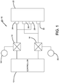
- the brake system 10 includes a controller 12 interconnected with a pair of independently controlled brake control valves 14, 16, each respectively associated with either its own hydraulic system 18, 20 or a single common source.
- An aircraft brake assembly 22 is also provided consisting of a pressure plate, endplate, and interposed, alternatingly interleaved stator and rotor brake disks, in somewhat standard fashion.
- the brake disks are of a carbon-carbon construction.
- brake-actuating piston assemblies 24, 26, 28, 30 are connected to the brake control valves 14, 16, and the actuation of the pistons is controlled by the controller 12.
- piston assemblies 24, 28 are in paired connection with the brake control valve 14, while the pistons 26, 30 are in paired interconnection with the brake control valve 16.
- the controller 12 may, during high-energy stops, control brake control valves 14, 16 in tandem, such that all of the pistons 24-30 are actuated in unison. This would typically be the arrangement during landing.
- only one of the valves 14, 16 may be selected for operation by the controller 12, such that either the pair of pistons 24, 28 or the pair 26, 30 is actuated.
- these low-energy braking operations by using only half of the brake pistons, a greater force is required to be exerted on the pressure plate by these few pistons than if all four were being applied.
- pistons 24-30 are typically uniformly positioned about the pressure plate, and the pairing of the pistons would typically be such as to achieve a uniform pairing across the surface of the pressure plate. Accordingly, where the piston engages the pressure plate and the pressure plate engages the heat stack, the force will be greater and more localized than when all of the pistons are employed.
- the determination of the braking arrangement may be under pilot control or achieved upon occurrence of an event. For example, a threshold ground speed may be set, below which only one of the valves 14, 16 operates, and above which both operate. Alternatively, when brake pedal travel exceeds a first high level, such as 80%, both valves 14, 16 are enabled, but when below a lesser threshold, only one would control.
- a threshold ground speed may be set, below which only one of the valves 14, 16 operates, and above which both operate.
- a first high level such as 80%
- both valves 14, 16 are enabled, but when below a lesser threshold, only one would control.
- the pressure plate 32 has a wear surface 34, which typically engages the first rotor of the heat stack of stators and rotors. While typically the pressure plate 34 is totally flat and has a surface that is totally parallel to that of the first rotor of the heat stack, this embodiment of the invention deviates from that concept.
- the wear surface 34 of the pressure plate has a taper angle 36 of a very slight amount, typically on the order of 0.25-1.5 degrees, and most preferably on the order of about 0.7 degrees. It has been found that employing such a taper again allows for the concentration of force toward the inner diameter of the pressure plate and associated stator and rotor disks during low energy braking activities, such as during taxiing, resulting in a reduction of noise.
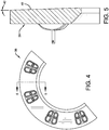
- Figs. 4 and 5 show a similar augmentation to the endplate 38, where the wear surface or contact surface 40 is characterized by a taper angle 42 of a similar nature to that discussed above with regard to the pressure plate 32.
- the wear surface or contact surface 40 is characterized by a taper angle 42 of a similar nature to that discussed above with regard to the pressure plate 32.
- the endplate or pressure plate may be formed of a gradient of carbon-carbon material exhibiting a varying wear rate extending radially from the center of the plate to its outer circumference.
- the slower-wearing mix of carbon-carbon composite would be near the center of the plate, with the faster-wearing composite mix being at the outer surface, the gradient changing as a function of contemplated braking activity and resultant wear.
- a portion of a brake assembly 44 includes a brake actuating piston 46 operating against a pressure plate 48, which is urged against a first rotor of the heat stack 50, which in turn is urged against a first stator 52.
- the friction surface interface 54 between the pressure plate 48 and first rotor 50 is, as clearly apparent, less than the friction interfaces between the stators and rotors in the heat stack.
- a portion of a brake assembly 62 is shown as consisting of a pressure plate 64, a first rotor 66, and a first stator 68.
- the pressure plate 64 is actuated by appropriate pistons 46.
- the wear surface interface 70 between the first rotor 66 and the pressure plate 64 is defined by a plurality of uniformly spaced wear surfaces 72 separated by uniformly spaced recessed surfaces 74. It will be appreciated that the recessed areas 74 are machined away during the manufacturing process.
- the surface of the first rotor 66 is totally planar, without any such recesses.
- the pressure or forces imparted to the first rotor 66 are again localized, accentuated, and uniformly spaced. Accordingly, the noise generally characteristic of low-energy stops is dissipated because the interface between the pressure plate 64 and first rotor 66 is sufficiently reduced such that the force and pressure characteristics at this interface are comparatively increased, characteristic of those of higher-energy stops, where noise is typically not a problem.
- a disk 76 which may be either a stator or rotor disk, is designated by the numeral 76.
- various slots are placed in the disk for purposes of prohibiting traveling waves from developing across the disk. It has been found that a single slot may be employed, or that multiple slots of varying characteristics can be employed, the choice, selection and combination allowing the disk to be tuned as a function of the carbon material employed, the forces and pressures anticipated, and the noise characteristics otherwise experienced.
- Disks have been developed using a single slot 78 extending from the outside diameter (OD) of the disk radially toward the inside diameter (ID), and here being on the order of 80% of the extension from the OD to the ID.
- the invention also contemplates the use of a shorter slot 80, extending from the OD radially toward the ID, but on the order of 50% or less of that distance.
- the invention also contemplates the employment of a radial slot 82 that is machined totally within the disk, not reaching either the outer circumference or the inner circumference of the disk, but being totally contained between the two.
- slots may be utilized, such as the slot 84, which is similar to the slot 78, but not fully radial; rather it is canted or angled with respect to the center of the disk 76. A more accentuated canting or angling is apparent with the slot 86, somewhat shorter than the slot 84, but angled more significantly with respect to the center of the disk 76.
- the positioning, length, width, and degree of radial deviation allows for a tuning of the disk to achieve a desired noise reduction, attenuation or elimination.
- the invention further contemplates that the grooves that extend to the outer circumference of the disk 76 may serve to alter the localized wear rate of the disk by providing paths for carbon dust to escape as the pressure plate (or endplate, as the case may be), contacts the adjacent rotor in braking engagement.
- the grooves serve to wipe the dust from the interface between the outside rotors and the engaged pressure plate and endplate, increasing braking efficiency and wear.
- the invention contemplates that the ends of the slots will be radiused, as shown, for purposes of structural integrity and to discourage cracks developing from the ends of the slots.
- a pressure plate assembly is designated generally by the numeral 88, it being understood that the concept of this embodiment can readily be extended to an endplate as well as a pressure plate.
- the pressure plate assembly 88 includes brake actuators 90 uniformly spaced thereabout, as shown in Fig. 11 .
- the pressure plate 92 is of a split or bifurcated design, comprising a face plate 92a and a back plate 92b.
- the face plate 92a is of a carbon composite material and is of a cup-shaped design having a circumferential outer lip 92c extending thereabout.
- the back plate 92b may be of any suitable construction, carbon, steel or the like, and is nestingly received by the cup of the face plate 92a.
- the face plate 92a is of substantially uniform thickness, while the back plate 92b has a tapered inner surface as shown.
- the taper of the inner surface of the back plate 92b is on the order of 0.5-2.0 degrees, and preferably at a taper of 1 degree.
- a sheet of material that provides vibration attenuation 94 is interposed between the face plate 92a and back plate 92b, the sheet having a nominal thickness of 0.01-0.10 inch and preferably 0.03 inch. It has been found that a suitable material for such purposes is sold under the trademark Grafoil and is a film of flexible graphite. Other suitable materials capable of attenuating vibrations in a high-temperature environment are contemplated.
- a plurality of rivet-clip assemblies 96 are uniformly spaced about the inner circumference of the pressure plate assembly 88 to hold the plates 92a, 92b in place with the sheet 94 sandwiched therebetween in secure contacting engagement.
- the gap between the plates 92a and 92b at their outer circumference is on the order of 0.06-0.10 inch and preferably 0.08 inch. With the sheet 94 preferably taking up 0.03 inch of that space, a nominal 0.05 inch gap remains to be taken up during braking activity.
- the sheet 94 serves as a dampening agent, damping physical vibrations and sounds.
- the taper of the back plate 92b allows for the concentration of force toward the inner diameter of the annular pressure plate and associated stator and rotor disks during low-energy braking activities, such as taxiing, resulting in reduction of noise.
- the gap between the plates 92a, 92b closes and the forceful engagement of stators and rotors with each other and the pressure plate and endplate extends more broadly over their entire surface, effecting greater braking force.
- damping and elimination of noise during low-energy braking operations is achieved, while the capability of standard braking operations during high-energy braking and the like remains.
- Another example not part of the invention employs a reduced frictional interface toward the inner diameter of the rotor and pressure plate so as to concentrate the force toward this region, without the need of a tapered structure as presented in embodiments above.
- a pressure plate 98 is provided with an inner region 100 and an outer region 102, the outer region 102 being of reduced thickness, as best shown in Fig. 14 .
- the reduction in thickness at the region 102 is on the order of 0.07-0.10 inch, and most preferably 0.085 inch.
- Clip assemblies 104 are provided about an inner circumferential edge of the pressure plate assembly 98, in somewhat standard fashion.
- the rotor subassembly to be used in association with the pressure plate 98 is shown in Figs. 15 and 16 , designated generally by the numeral 106.
- the wear surface of the rotor 106 is divided into an inner region 108 and an outer region 110. As shown in Fig. 16 , these regions are of the same thickness, and separated by a circular recess 112.
- This circular recess has a depth on the order of 0.045-0.065 inch, and most preferably 0.055 inch.
- the width of the circular recess is on the order of 0.115-0.135 inch, and most preferably 0.125 inch.
- the circular recess 112 is in alignment with the demarcation between the outer region 102 and the inner region 100 of the pressure plate 98.
Landscapes
- Engineering & Computer Science (AREA)
- General Engineering & Computer Science (AREA)
- Mechanical Engineering (AREA)
- Braking Arrangements (AREA)
Description
- The invention herein resides in the art of braking systems and, more particularly, to braking systems for aircraft. More specifically, the invention relates to configurations of brake assemblies and the constituent parts thereof for reducing noise during aircraft braking activities.
- Presently, aircraft brake assemblies typically include a heat stack of alternatingly interleaved stator and rotor disks of a carbon composition. The disks are maintained between pressure plate and endplate disks such that the application of pressure and resulting force to the pressure plate causes the stators and rotor disks to frictionally engage, causing mechanical energy to dissipate as heat in the heat stack as the aircraft is brought to a stop. A state of the art aircraft brake assembly is shown in document
US 2004/011602 A1 . - The generation of noise in the brake assemblies resulting from the interengagement of the disks with each other and/or the pressure plate and endplate has often been a problem attendant to the use of the otherwise preferred carbon brake assemblies. The problem often seems to be most pronounced during low-energy stops, such as during taxiing and the like. While the attendant noise is typically not indicative of any deficiencies or shortcomings in the efficacy of the brake system, it is often annoying and disconcerting to passengers. Accordingly, it is desired to eliminate, or at least attenuate, such noise without adverse effects on the braking operation.
- In the past, approaches to such noise suppression or attenuation has focused on either modifying or adjusting the carbon mix employed in making the stator and rotor disks or in employing various types of mechanical vibration or oscillation dampers to physically dampen the noise generated by the disks during a braking activity. Neither of these approaches has resulted in much success, and has often had concomitant reduction in braking efficiency or increase in manufacturing costs.
- In light of the foregoing, it is an aspect of the present invention to provide aircraft brake assembly structures for reducing noise by selectively controlling the number of brake actuator pistons employed at times when noise is typically generated.
- Another aspect of the invention is to provide an aircraft brake assembly structure for reducing noise that modifies the configuration of the pressure plate or endplate of the brake assembly by providing a tapered interface to those structures.
- Still a further aspect of the invention is the provision of aircraft brake assembly structures for reducing noise wherein the wear surface interface between the pressure plate and a first rotor of the heat stack is adjusted to effectively maximize the forceful engagement between the two over a reduced area.
- It is further an aspect of the invention to provide aircraft brake assembly structures for reducing noise that are cost effective, easy to implement, and which do not result in reduction in braking efficiency.
- The foregoing and other aspects of the invention are achieved by an aircraft brake assembly according to claim 1.
- Other aspects of the invention that will become apparent herein are achieved by an aircraft brake assembly configured to minimize noise during braking, comprising a heat stack of alternating interleaved stators and rotors between a pressure plate and endplate, wherein at least certain of said stators and rotors are characterized by slots therethrough, said slots breaking up a propagation of vibrational waves during braking.
- For a complete understanding of various aspects of the invention, reference should be made to the following detailed description and accompanying drawings wherein:
-
Fig. 1 is a schematic diagram of an aircraft brake system employing a first embodiment of the invention in which sets of brake actuator pistons are separately controlled; -
Fig. 2 is a partial sectional view of a pressure plate modified to taper in accordance with an embodiment of the invention; -
Fig. 3 is a cross-sectional view of the pressure plate ofFig. 2 , taken along the line 3-3; -
Fig. 4 is an endplate, modified to contain a taper in accordance with another embodiment of the invention; -
Fig. 5 is a cross-sectional view of the endplate ofFig. 4 , taken along the line 5-5; -
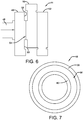
Fig. 6 is an illustration, not part of the invention, of a portion of a brake assembly employing a pressure plate and first rotor machined to have a reduced frictional contact area; -
Fig. 7 is a plan view of the pressure plate ofFig. 6 ; -
Fig. 8 is an illustration of a portion of a brake assembly not part of the invention; -
Fig. 9 is a plan view of the pressure plate employed in the example ofFig. 8 , showing machined recess portions between wear surfaces; -
Fig. 10 is a plan view of a brake disk according to another example not part of the invention characterized by various slots interposed for purposes of attenuating noise; -
Fig. 11 is a partial view of a pressure plate made in accordance with another embodiment of the invention; -
Fig. 12 is a cross-sectional view of the pressure plate ofFig. 11 taken along the line 12-12, showing the pressure plate to comprise a pair of disks separated by a tapered gap having a vibration-attenuating material layer therein; -
Fig. 13 is a partial view of a pressure plate subassembly made in accordance with yet another example not part of the invention; -
Fig. 14 is a cross-sectional view of pressure plate subassembly ofFig. 13 , taken along the line 14-14; -
Fig. 15 is a partial view of a rotor subassembly made in accordance with the example not part of the invention shown inFigs. 13 and14 ; and -
Fig. 16 is a cross-sectional view of the rotor subassembly ofFig. 15 , taken along the line 16-16. - Referring now to the drawings and more particularly
Fig. 1 , it can be seen that an aircraft brake system in accordance with a first embodiment of the invention is designated generally by thenumeral 10. Thebrake system 10 includes acontroller 12 interconnected with a pair of independently controlledbrake control valves hydraulic system aircraft brake assembly 22 is also provided consisting of a pressure plate, endplate, and interposed, alternatingly interleaved stator and rotor brake disks, in somewhat standard fashion. In the preferred embodiment of the invention, the brake disks are of a carbon-carbon construction. - Those skilled in the art will appreciate that the application of pressure or force to the pressure plate urges the stators and rotors into frictional engagement to achieve the desired braking action. In that regard, brake-actuating piston assemblies 24, 26, 28, 30 are connected to the
brake control valves controller 12. - As shown in
Fig. 1 ,piston assemblies brake control valve 14, while thepistons brake control valve 16. With this type of architecture, thecontroller 12 may, during high-energy stops, controlbrake control valves valves controller 12, such that either the pair ofpistons pair - The determination of the braking arrangement may be under pilot control or achieved upon occurrence of an event. For example, a threshold ground speed may be set, below which only one of the
valves valves - With reference now to
Figs. 2-5 , an appreciation may be obtained of other embodiments of the invention wherein augmentations are made to the pressure plate and/or endplate of a brake assembly, such as thebrake assembly 22, described above. As shown, thepressure plate 32 has awear surface 34, which typically engages the first rotor of the heat stack of stators and rotors. While typically thepressure plate 34 is totally flat and has a surface that is totally parallel to that of the first rotor of the heat stack, this embodiment of the invention deviates from that concept. As shown inFig. 3 , thewear surface 34 of the pressure plate has ataper angle 36 of a very slight amount, typically on the order of 0.25-1.5 degrees, and most preferably on the order of about 0.7 degrees. It has been found that employing such a taper again allows for the concentration of force toward the inner diameter of the pressure plate and associated stator and rotor disks during low energy braking activities, such as during taxiing, resulting in a reduction of noise. -
Figs. 4 and 5 show a similar augmentation to theendplate 38, where the wear surface orcontact surface 40 is characterized by ataper angle 42 of a similar nature to that discussed above with regard to thepressure plate 32. In practice, while it has been found that taper of the contact faces of the pressure plate and endplate both contribute to noise attenuation or reduction, the same has been most prominent when the pressure plate is tapered. - When the pressure plate or endplate is tapered as discussed with regard to
Figs. 2-5 , there is a concern that thewear rates pressure plate 32 andendplate 38 are such that the desiredtaper angles - Referring now to
Figs. 6 and 7 , an appreciation can be obtained with regard to an example not part of the invention wherein the pressure plate and the first rotor of the brake assembly, such as thebrake assembly 22, are machined to have a reduced frictional interface therebetween, resulting in a concentrated, localized, and increased application of force or pressure during braking activity. As shown, a portion of abrake assembly 44 includes abrake actuating piston 46 operating against apressure plate 48, which is urged against a first rotor of theheat stack 50, which in turn is urged against afirst stator 52. Thefriction surface interface 54 between thepressure plate 48 andfirst rotor 50 is, as clearly apparent, less than the friction interfaces between the stators and rotors in the heat stack. This is achieved by machining away portions of thepressure plate 48 andfirst rotor 50, which would otherwise be present. This is shown inFig. 7 , where thewear surface 56 of the pressure plate is defined betweenrecesses pressure plate 48. Similar action has taken place with regard to thefirst rotor 50, such that thewear surface 56 of the pressure plate is congruent with the wear surface of thefirst rotor 50 so that there is no nesting capability between the two. It will be appreciated that the placement of thefriction surface interface 54 may preferably be toward the inner diameter of thepressure plate 48 androtor 50 to concentrate the force in the inner region as with the tapered embodiments, above. - As shown in
Figs. 8 and 9 , yet another example not part of the invention, similar to that ofFigs. 6 and 7 , is shown. Here, a portion of abrake assembly 62 is shown as consisting of apressure plate 64, afirst rotor 66, and afirst stator 68. Again, thepressure plate 64 is actuated byappropriate pistons 46. In this embodiment, thewear surface interface 70 between thefirst rotor 66 and thepressure plate 64 is defined by a plurality of uniformly spaced wear surfaces 72 separated by uniformly spaced recessed surfaces 74. It will be appreciated that the recessedareas 74 are machined away during the manufacturing process. The surface of thefirst rotor 66 is totally planar, without any such recesses. Employing this structure, the pressure or forces imparted to thefirst rotor 66 are again localized, accentuated, and uniformly spaced. Accordingly, the noise generally characteristic of low-energy stops is dissipated because the interface between thepressure plate 64 andfirst rotor 66 is sufficiently reduced such that the force and pressure characteristics at this interface are comparatively increased, characteristic of those of higher-energy stops, where noise is typically not a problem. - With reference now to
Fig. 10 , yet a further approach, not part of the invention, to noise reduction in a brake assembly is shown where adisk 76, which may be either a stator or rotor disk, is designated by the numeral 76. Here, various slots are placed in the disk for purposes of prohibiting traveling waves from developing across the disk. It has been found that a single slot may be employed, or that multiple slots of varying characteristics can be employed, the choice, selection and combination allowing the disk to be tuned as a function of the carbon material employed, the forces and pressures anticipated, and the noise characteristics otherwise experienced. Disks have been developed using asingle slot 78 extending from the outside diameter (OD) of the disk radially toward the inside diameter (ID), and here being on the order of 80% of the extension from the OD to the ID. The invention also contemplates the use of ashorter slot 80, extending from the OD radially toward the ID, but on the order of 50% or less of that distance. The invention also contemplates the employment of aradial slot 82 that is machined totally within the disk, not reaching either the outer circumference or the inner circumference of the disk, but being totally contained between the two. - Other slots may be utilized, such as the
slot 84, which is similar to theslot 78, but not fully radial; rather it is canted or angled with respect to the center of thedisk 76. A more accentuated canting or angling is apparent with theslot 86, somewhat shorter than theslot 84, but angled more significantly with respect to the center of thedisk 76. The positioning, length, width, and degree of radial deviation allows for a tuning of the disk to achieve a desired noise reduction, attenuation or elimination. The invention further contemplates that the grooves that extend to the outer circumference of thedisk 76 may serve to alter the localized wear rate of the disk by providing paths for carbon dust to escape as the pressure plate (or endplate, as the case may be), contacts the adjacent rotor in braking engagement. The grooves serve to wipe the dust from the interface between the outside rotors and the engaged pressure plate and endplate, increasing braking efficiency and wear. - The invention contemplates that the ends of the slots will be radiused, as shown, for purposes of structural integrity and to discourage cracks developing from the ends of the slots.
- A further embodiment of the invention is shown in
Figs. 11 and12 . Here, a pressure plate assembly is designated generally by the numeral 88, it being understood that the concept of this embodiment can readily be extended to an endplate as well as a pressure plate. Thepressure plate assembly 88 includesbrake actuators 90 uniformly spaced thereabout, as shown inFig. 11 . Thepressure plate 92 is of a split or bifurcated design, comprising aface plate 92a and aback plate 92b. According to a preferred embodiment of the invention, theface plate 92a is of a carbon composite material and is of a cup-shaped design having a circumferentialouter lip 92c extending thereabout. Theback plate 92b may be of any suitable construction, carbon, steel or the like, and is nestingly received by the cup of theface plate 92a. Theface plate 92a is of substantially uniform thickness, while theback plate 92b has a tapered inner surface as shown. The taper of the inner surface of theback plate 92b is on the order of 0.5-2.0 degrees, and preferably at a taper of 1 degree. A sheet of material that providesvibration attenuation 94 is interposed between theface plate 92a and backplate 92b, the sheet having a nominal thickness of 0.01-0.10 inch and preferably 0.03 inch. It has been found that a suitable material for such purposes is sold under the trademark Grafoil and is a film of flexible graphite. Other suitable materials capable of attenuating vibrations in a high-temperature environment are contemplated. - A plurality of rivet-
clip assemblies 96 are uniformly spaced about the inner circumference of thepressure plate assembly 88 to hold theplates sheet 94 sandwiched therebetween in secure contacting engagement. At the outer circumference, due to the tapered nature of theback plate 92b, the gap between theplates sheet 94 preferably taking up 0.03 inch of that space, a nominal 0.05 inch gap remains to be taken up during braking activity. - The
sheet 94 serves as a dampening agent, damping physical vibrations and sounds. In use, the taper of theback plate 92b allows for the concentration of force toward the inner diameter of the annular pressure plate and associated stator and rotor disks during low-energy braking activities, such as taxiing, resulting in reduction of noise. As pressure increases for normal braking, the gap between theplates - Another example not part of the invention employs a reduced frictional interface toward the inner diameter of the rotor and pressure plate so as to concentrate the force toward this region, without the need of a tapered structure as presented in embodiments above.
- With reference to
Figs. 13-16 , pressure plate and rotor subassemblies made in accordance with this embodiment of the invention are shown. According toFig. 13 , apressure plate 98 is provided with aninner region 100 and anouter region 102, theouter region 102 being of reduced thickness, as best shown inFig. 14 . According to a preferred embodiment of the invention, the reduction in thickness at theregion 102 is on the order of 0.07-0.10 inch, and most preferably 0.085 inch.Clip assemblies 104 are provided about an inner circumferential edge of thepressure plate assembly 98, in somewhat standard fashion. The rotor subassembly to be used in association with thepressure plate 98 is shown inFigs. 15 and16 , designated generally by the numeral 106. Here again, the wear surface of therotor 106 is divided into aninner region 108 and anouter region 110. As shown inFig. 16 , these regions are of the same thickness, and separated by acircular recess 112. This circular recess has a depth on the order of 0.045-0.065 inch, and most preferably 0.055 inch. The width of the circular recess is on the order of 0.115-0.135 inch, and most preferably 0.125 inch. In a brake disk stack, thecircular recess 112 is in alignment with the demarcation between theouter region 102 and theinner region 100 of thepressure plate 98. Accordingly, during low-energy braking such as taxiing and the like, high-pressure or high-force braking is engaged between theinner region 100 of thepressure plate assembly 98 and theinner region 108 of the rotor subassembly. Accordingly, even during taxiing and low-energy stops, there is forceful engagement at these surfaces of sufficient magnitude as to reduce the noise commonly incident to low-energy stops. During high-energy stops, the force imparted by the pistons to the pressure plate is sufficient to close the gap between theouter regions Riveted clip assemblies 114 are provided about the outer circumferential edge of therotor 106, in standard fashion. - Thus it can be seen that the various aspects of the invention have been achieved by the embodiments presented and described above. While in accordance with the patent statutes, only preferred embodiments of the invention have been presented and described in detail, the invention is not limited thereto or thereby. For an appreciation of the true scope and breadth of the invention, reference should be made to the following claims.
Claims (12)
- An aircraft brake assembly configured to minimize noise during braking, comprising:a heat stack (50) of alternating interleaved stator disks and rotor disks between a pressure plate (32) and endplate (38), characterised bymeans for altering a force pattern from one of said pressure plate (32) and said endplate (38) upon said heat stack (50) as a function of a magnitude of braking force applied to said heat stack as between high-energy landing and low-energy taxiing operations, said means for altering a force pattern comprising one of said pressure plate and endplate comprising a disk radially tapered (36,42) in thickness from a thicker inner region to a thinner outer region.
- The aircraft braking assembly according to claim 1, wherein said one of said pressure plate (32) and endplate (38) has a wear surface (34,40), and only said wear surface (34,40) is tapered.
- The aircraft braking assembly according to claim 2, wherein said taper (36,42) is at an angle of 0.25-1.5 degrees.
- The aircraft braking assembly according to claim 3, wherein said wear surface (34,40) is formed of a carbon-carbon mix of material.
- The aircraft braking assembly according to claim 4, wherein said mix of carbon-carbon material is slower wearing near a center of said one of said pressure plate (32) and endplate (38) and faster wearing near a radial outer region thereof.
- The aircraft braking assembly according to claim 5, wherein said one of said pressure plate (32) and endplate (38) is characterized by a gradient of wear characteristics of said mix of carbon-carbon material from slower wearing near said center to faster wearing near said radial outer region.
- The aircraft braking assembly according to claim 1, wherein said disk of said pressure plate (32) and endplate (38) is bifurcated, having a face plate (92a) and a back plate (92b), said face plate (92a) being of a uniform thickness and having a wear surface, and said back plate (92b) being tapered on a surface adjacent said face plate.
- The aircraft braking assembly according to claim 7, further comprising a film (94) of flexible graphite sandwiched between said face plate (92a) and back plate (92b).
- The aircraft braking assembly according to claim 8, wherein said taper is on the order of 0.5-1.5 degrees.
- The aircraft braking assembly according to claim 9, wherein said film (94) of flexible graphite is of a thickness of 0.02-0.04 inch.
- The aircraft braking assembly according to claim 8, wherein said face plate (92a) is cup-shaped and receives said back plate (92b).
- The aircraft braking assembly according to claim 11, wherein said face plate (92a) is of carbon and said back plate (92b) is of steel construction.
Applications Claiming Priority (2)
| Application Number | Priority Date | Filing Date | Title |
|---|---|---|---|
| US201462048443P | 2014-09-10 | 2014-09-10 | |
| PCT/US2015/049320 WO2016040561A1 (en) | 2014-09-10 | 2015-09-10 | Aircraft brake assembly structures for reducing noise |
Publications (2)
| Publication Number | Publication Date |
|---|---|
| EP3191727A1 EP3191727A1 (en) | 2017-07-19 |
| EP3191727B1 true EP3191727B1 (en) | 2018-10-31 |
Family
ID=54252365
Family Applications (1)
| Application Number | Title | Priority Date | Filing Date |
|---|---|---|---|
| EP15775282.5A Active EP3191727B1 (en) | 2014-09-10 | 2015-09-10 | Aircraft brake assembly structures for reducing noise |
Country Status (6)
| Country | Link |
|---|---|
| US (2) | US10316908B2 (en) |
| EP (1) | EP3191727B1 (en) |
| BR (1) | BR112017004856B1 (en) |
| CA (1) | CA2960843C (en) |
| ES (1) | ES2707359T3 (en) |
| WO (1) | WO2016040561A1 (en) |
Family Cites Families (29)
| Publication number | Priority date | Publication date | Assignee | Title |
|---|---|---|---|---|
| US3008547A (en) * | 1956-05-21 | 1961-11-14 | Edward A Rockwell | Mechanical booster brake |
| US3010543A (en) * | 1959-11-16 | 1961-11-28 | Lambert & Brake Corp | High-speed disc brake |
| US3198295A (en) * | 1963-02-21 | 1965-08-03 | Caterpillar Tractor Co | Friction couple cooling device |
| US3708042A (en) * | 1970-09-21 | 1973-01-02 | Bendix Corp | Carbon core segmented friction disc |
| US3800392A (en) * | 1970-11-05 | 1974-04-02 | Goodyear Tire & Rubber | Graphite and/or carbon disk with removable wear faces |
| US3951240A (en) * | 1971-10-07 | 1976-04-20 | Dunlop Limited | Frictional disc arrangement for a disc brake |
| US3972395A (en) * | 1974-03-29 | 1976-08-03 | The Bendix Corporation | Oxidation inhibiting caps for carbon friction disc |
| FR2557240B1 (en) * | 1983-12-21 | 1989-05-19 | Europ Propulsion | BRAKE DISC WITH REMOVABLE LININGS |
| US4878563A (en) * | 1984-07-13 | 1989-11-07 | The B.F. Goodrich Company | Brake apparatus |
| US4585096A (en) * | 1984-08-03 | 1986-04-29 | The B. F. Goodrich Company | Brake apparatus |
| US5050940A (en) * | 1990-02-05 | 1991-09-24 | Allied-Signal Inc. | Brake control and anti-skid system |
| FR2701006B1 (en) * | 1993-02-01 | 1995-03-10 | Messier Bugatti | Method for controlling an electro-hydraulic braking device of an aircraft wheel train, and device for implementing said method. |
| US5769185A (en) * | 1995-05-25 | 1998-06-23 | Aircraft Braking Systems Corporation | Carbon brake disc structures and method of making same |
| EP1116893B2 (en) * | 1996-03-19 | 2005-09-07 | Exedy Corporation | Multi-plate dry clutch having hub movement limiting means |
| FR2842496B1 (en) * | 2002-07-19 | 2005-02-11 | Messier Bugatti | BRAKING SYSTEM FOR AIRCRAFT WHEELS |
| US7159698B2 (en) * | 2004-07-22 | 2007-01-09 | Bendix Spicer Foundation Brake, Llc | Disc brake rotor assembly with replaceable wear surfaces |
| WO2009089551A2 (en) * | 2008-01-11 | 2009-07-16 | General Atomics | Braking system with linear actuator |
| US8590985B2 (en) * | 2008-09-30 | 2013-11-26 | Goodrich Corporation | Method to degrade braking modes |
| US9216720B2 (en) * | 2009-04-30 | 2015-12-22 | Goodrich Corporation | Differential emergency/park electric brake system |
| IT1395712B1 (en) * | 2009-09-10 | 2012-10-19 | Gaia | DEVICE AND METHOD FOR A WHEEL ROTATION OF AIRCRAFT LANDING TROLLEYS |
| US10040543B2 (en) * | 2010-03-12 | 2018-08-07 | Goodrich Corporation | Tapered brake disk |
| US9669810B2 (en) * | 2012-01-10 | 2017-06-06 | Honeywell International Inc. | Brake assembly including independently activatable brake actuators |
| FR3000004B1 (en) * | 2012-12-21 | 2016-12-23 | Messier Bugatti Dowty | METHOD FOR BRAKING AN AIRCRAFT |
| US8978843B2 (en) * | 2012-12-26 | 2015-03-17 | Goodrich Corporation | Brake disk assembly |
| US9315261B2 (en) * | 2013-06-26 | 2016-04-19 | Goodrich Corporation | Keyed brake disk assembly |
| US9127731B2 (en) * | 2013-06-27 | 2015-09-08 | Goodrich Corporation | System and method for brake disk assembly |
| US9376093B2 (en) * | 2013-11-07 | 2016-06-28 | Goodrich Corporation | System and method for independent braking system enablement |
| GB2528317A (en) * | 2014-07-18 | 2016-01-20 | Airbus Operations Sas | Differential braking of aircraft landing gear wheels |
| US9482299B1 (en) * | 2015-07-09 | 2016-11-01 | Goodrich Corporation | Multi-leaved core brake disks and assemblies |
-
2015
- 2015-09-10 US US15/510,012 patent/US10316908B2/en active Active
- 2015-09-10 CA CA2960843A patent/CA2960843C/en active Active
- 2015-09-10 ES ES15775282T patent/ES2707359T3/en active Active
- 2015-09-10 EP EP15775282.5A patent/EP3191727B1/en active Active
- 2015-09-10 WO PCT/US2015/049320 patent/WO2016040561A1/en not_active Ceased
- 2015-09-10 BR BR112017004856-6A patent/BR112017004856B1/en active IP Right Grant
-
2019
- 2019-04-26 US US16/395,448 patent/US20190249729A1/en not_active Abandoned
Non-Patent Citations (1)
| Title |
|---|
| None * |
Also Published As
| Publication number | Publication date |
|---|---|
| ES2707359T3 (en) | 2019-04-03 |
| CA2960843A1 (en) | 2016-03-17 |
| US10316908B2 (en) | 2019-06-11 |
| US20190249729A1 (en) | 2019-08-15 |
| BR112017004856B1 (en) | 2023-03-07 |
| BR112017004856A2 (en) | 2017-12-26 |
| US20170299002A1 (en) | 2017-10-19 |
| EP3191727A1 (en) | 2017-07-19 |
| CA2960843C (en) | 2023-01-17 |
| WO2016040561A1 (en) | 2016-03-17 |
Similar Documents
| Publication | Publication Date | Title |
|---|---|---|
| US3198295A (en) | Friction couple cooling device | |
| KR102142933B1 (en) | Linear brake operated by means of external energy | |
| JP2620454B2 (en) | Pressure release type seal structure | |
| KR101914253B1 (en) | Brake pistons and piston noses | |
| EP3173650B1 (en) | Damper brake | |
| EP0747610B1 (en) | A brake disk with built-in acoustic wear-warning device | |
| US3759354A (en) | Brake disc structure | |
| US3233704A (en) | Brake disc and hub mounting means | |
| US20120141276A1 (en) | Frequency-dependent damper and rotary wing system | |
| JP2907542B2 (en) | Power transmission assembly with shock absorber | |
| CA2960843C (en) | Aircraft brake assembly structures for reducing noise | |
| KR20230065908A (en) | Brake pad assembly for a disk brake system and disk brake system | |
| SE1650185A1 (en) | Cutting tool assembly with controlled resilience using hyperelastic materials | |
| EP4063682B1 (en) | Brake assembly | |
| US10316900B2 (en) | Lift fan clutch plate to reduce instability | |
| US10883554B2 (en) | Braking or clutch assembly for rotating shafts | |
| US3072220A (en) | Disc-type brake with vibration absorbing means | |
| JP2017519956A5 (en) | ||
| US3891066A (en) | Keyway drive for multiple disc brake | |
| EP3171050B1 (en) | Damped heatsink disk brake assembly | |
| KR102167451B1 (en) | Clutch disk assembly | |
| US4702351A (en) | Self-energizing disc brakes | |
| CN113446330A (en) | Brake and motor | |
| JPH0319622Y2 (en) | ||
| KR102594511B1 (en) | Torque converter for vehilce |
Legal Events
| Date | Code | Title | Description |
|---|---|---|---|
| STAA | Information on the status of an ep patent application or granted ep patent |
Free format text: STATUS: THE INTERNATIONAL PUBLICATION HAS BEEN MADE |
|
| PUAI | Public reference made under article 153(3) epc to a published international application that has entered the european phase |
Free format text: ORIGINAL CODE: 0009012 |
|
| STAA | Information on the status of an ep patent application or granted ep patent |
Free format text: STATUS: REQUEST FOR EXAMINATION WAS MADE |
|
| 17P | Request for examination filed |
Effective date: 20170307 |
|
| AK | Designated contracting states |
Kind code of ref document: A1 Designated state(s): AL AT BE BG CH CY CZ DE DK EE ES FI FR GB GR HR HU IE IS IT LI LT LU LV MC MK MT NL NO PL PT RO RS SE SI SK SM TR |
|
| AX | Request for extension of the european patent |
Extension state: BA ME |
|
| DAV | Request for validation of the european patent (deleted) | ||
| DAX | Request for extension of the european patent (deleted) | ||
| GRAP | Despatch of communication of intention to grant a patent |
Free format text: ORIGINAL CODE: EPIDOSNIGR1 |
|
| STAA | Information on the status of an ep patent application or granted ep patent |
Free format text: STATUS: GRANT OF PATENT IS INTENDED |
|
| INTG | Intention to grant announced |
Effective date: 20180619 |
|
| GRAS | Grant fee paid |
Free format text: ORIGINAL CODE: EPIDOSNIGR3 |
|
| GRAA | (expected) grant |
Free format text: ORIGINAL CODE: 0009210 |
|
| STAA | Information on the status of an ep patent application or granted ep patent |
Free format text: STATUS: THE PATENT HAS BEEN GRANTED |
|
| AK | Designated contracting states |
Kind code of ref document: B1 Designated state(s): AL AT BE BG CH CY CZ DE DK EE ES FI FR GB GR HR HU IE IS IT LI LT LU LV MC MK MT NL NO PL PT RO RS SE SI SK SM TR |
|
| REG | Reference to a national code |
Ref country code: CH Ref legal event code: EP Ref country code: GB Ref legal event code: FG4D |
|
| REG | Reference to a national code |
Ref country code: AT Ref legal event code: REF Ref document number: 1059778 Country of ref document: AT Kind code of ref document: T Effective date: 20181115 |
|
| REG | Reference to a national code |
Ref country code: IE Ref legal event code: FG4D |
|
| REG | Reference to a national code |
Ref country code: DE Ref legal event code: R096 Ref document number: 602015019211 Country of ref document: DE |
|
| REG | Reference to a national code |
Ref country code: NL Ref legal event code: MP Effective date: 20181031 |
|
| REG | Reference to a national code |
Ref country code: LT Ref legal event code: MG4D |
|
| REG | Reference to a national code |
Ref country code: ES Ref legal event code: FG2A Ref document number: 2707359 Country of ref document: ES Kind code of ref document: T3 Effective date: 20190403 |
|
| REG | Reference to a national code |
Ref country code: AT Ref legal event code: MK05 Ref document number: 1059778 Country of ref document: AT Kind code of ref document: T Effective date: 20181031 |
|
| PG25 | Lapsed in a contracting state [announced via postgrant information from national office to epo] |
Ref country code: BG Free format text: LAPSE BECAUSE OF FAILURE TO SUBMIT A TRANSLATION OF THE DESCRIPTION OR TO PAY THE FEE WITHIN THE PRESCRIBED TIME-LIMIT Effective date: 20190131 Ref country code: LT Free format text: LAPSE BECAUSE OF FAILURE TO SUBMIT A TRANSLATION OF THE DESCRIPTION OR TO PAY THE FEE WITHIN THE PRESCRIBED TIME-LIMIT Effective date: 20181031 Ref country code: FI Free format text: LAPSE BECAUSE OF FAILURE TO SUBMIT A TRANSLATION OF THE DESCRIPTION OR TO PAY THE FEE WITHIN THE PRESCRIBED TIME-LIMIT Effective date: 20181031 Ref country code: NO Free format text: LAPSE BECAUSE OF FAILURE TO SUBMIT A TRANSLATION OF THE DESCRIPTION OR TO PAY THE FEE WITHIN THE PRESCRIBED TIME-LIMIT Effective date: 20190131 Ref country code: AT Free format text: LAPSE BECAUSE OF FAILURE TO SUBMIT A TRANSLATION OF THE DESCRIPTION OR TO PAY THE FEE WITHIN THE PRESCRIBED TIME-LIMIT Effective date: 20181031 Ref country code: IS Free format text: LAPSE BECAUSE OF FAILURE TO SUBMIT A TRANSLATION OF THE DESCRIPTION OR TO PAY THE FEE WITHIN THE PRESCRIBED TIME-LIMIT Effective date: 20190228 Ref country code: LV Free format text: LAPSE BECAUSE OF FAILURE TO SUBMIT A TRANSLATION OF THE DESCRIPTION OR TO PAY THE FEE WITHIN THE PRESCRIBED TIME-LIMIT Effective date: 20181031 Ref country code: HR Free format text: LAPSE BECAUSE OF FAILURE TO SUBMIT A TRANSLATION OF THE DESCRIPTION OR TO PAY THE FEE WITHIN THE PRESCRIBED TIME-LIMIT Effective date: 20181031 Ref country code: PL Free format text: LAPSE BECAUSE OF FAILURE TO SUBMIT A TRANSLATION OF THE DESCRIPTION OR TO PAY THE FEE WITHIN THE PRESCRIBED TIME-LIMIT Effective date: 20181031 |
|
| PG25 | Lapsed in a contracting state [announced via postgrant information from national office to epo] |
Ref country code: NL Free format text: LAPSE BECAUSE OF FAILURE TO SUBMIT A TRANSLATION OF THE DESCRIPTION OR TO PAY THE FEE WITHIN THE PRESCRIBED TIME-LIMIT Effective date: 20181031 Ref country code: AL Free format text: LAPSE BECAUSE OF FAILURE TO SUBMIT A TRANSLATION OF THE DESCRIPTION OR TO PAY THE FEE WITHIN THE PRESCRIBED TIME-LIMIT Effective date: 20181031 Ref country code: GR Free format text: LAPSE BECAUSE OF FAILURE TO SUBMIT A TRANSLATION OF THE DESCRIPTION OR TO PAY THE FEE WITHIN THE PRESCRIBED TIME-LIMIT Effective date: 20190201 Ref country code: SE Free format text: LAPSE BECAUSE OF FAILURE TO SUBMIT A TRANSLATION OF THE DESCRIPTION OR TO PAY THE FEE WITHIN THE PRESCRIBED TIME-LIMIT Effective date: 20181031 Ref country code: PT Free format text: LAPSE BECAUSE OF FAILURE TO SUBMIT A TRANSLATION OF THE DESCRIPTION OR TO PAY THE FEE WITHIN THE PRESCRIBED TIME-LIMIT Effective date: 20190301 Ref country code: RS Free format text: LAPSE BECAUSE OF FAILURE TO SUBMIT A TRANSLATION OF THE DESCRIPTION OR TO PAY THE FEE WITHIN THE PRESCRIBED TIME-LIMIT Effective date: 20181031 |
|
| PG25 | Lapsed in a contracting state [announced via postgrant information from national office to epo] |
Ref country code: CZ Free format text: LAPSE BECAUSE OF FAILURE TO SUBMIT A TRANSLATION OF THE DESCRIPTION OR TO PAY THE FEE WITHIN THE PRESCRIBED TIME-LIMIT Effective date: 20181031 Ref country code: DK Free format text: LAPSE BECAUSE OF FAILURE TO SUBMIT A TRANSLATION OF THE DESCRIPTION OR TO PAY THE FEE WITHIN THE PRESCRIBED TIME-LIMIT Effective date: 20181031 |
|
| REG | Reference to a national code |
Ref country code: DE Ref legal event code: R097 Ref document number: 602015019211 Country of ref document: DE |
|
| PG25 | Lapsed in a contracting state [announced via postgrant information from national office to epo] |
Ref country code: SM Free format text: LAPSE BECAUSE OF FAILURE TO SUBMIT A TRANSLATION OF THE DESCRIPTION OR TO PAY THE FEE WITHIN THE PRESCRIBED TIME-LIMIT Effective date: 20181031 Ref country code: EE Free format text: LAPSE BECAUSE OF FAILURE TO SUBMIT A TRANSLATION OF THE DESCRIPTION OR TO PAY THE FEE WITHIN THE PRESCRIBED TIME-LIMIT Effective date: 20181031 Ref country code: SK Free format text: LAPSE BECAUSE OF FAILURE TO SUBMIT A TRANSLATION OF THE DESCRIPTION OR TO PAY THE FEE WITHIN THE PRESCRIBED TIME-LIMIT Effective date: 20181031 Ref country code: RO Free format text: LAPSE BECAUSE OF FAILURE TO SUBMIT A TRANSLATION OF THE DESCRIPTION OR TO PAY THE FEE WITHIN THE PRESCRIBED TIME-LIMIT Effective date: 20181031 |
|
| PLBE | No opposition filed within time limit |
Free format text: ORIGINAL CODE: 0009261 |
|
| STAA | Information on the status of an ep patent application or granted ep patent |
Free format text: STATUS: NO OPPOSITION FILED WITHIN TIME LIMIT |
|
| 26N | No opposition filed |
Effective date: 20190801 |
|
| PG25 | Lapsed in a contracting state [announced via postgrant information from national office to epo] |
Ref country code: SI Free format text: LAPSE BECAUSE OF FAILURE TO SUBMIT A TRANSLATION OF THE DESCRIPTION OR TO PAY THE FEE WITHIN THE PRESCRIBED TIME-LIMIT Effective date: 20181031 |
|
| PG25 | Lapsed in a contracting state [announced via postgrant information from national office to epo] |
Ref country code: TR Free format text: LAPSE BECAUSE OF FAILURE TO SUBMIT A TRANSLATION OF THE DESCRIPTION OR TO PAY THE FEE WITHIN THE PRESCRIBED TIME-LIMIT Effective date: 20181031 |
|
| PG25 | Lapsed in a contracting state [announced via postgrant information from national office to epo] |
Ref country code: MC Free format text: LAPSE BECAUSE OF FAILURE TO SUBMIT A TRANSLATION OF THE DESCRIPTION OR TO PAY THE FEE WITHIN THE PRESCRIBED TIME-LIMIT Effective date: 20181031 |
|
| REG | Reference to a national code |
Ref country code: CH Ref legal event code: PL |
|
| PG25 | Lapsed in a contracting state [announced via postgrant information from national office to epo] |
Ref country code: CH Free format text: LAPSE BECAUSE OF NON-PAYMENT OF DUE FEES Effective date: 20190930 Ref country code: LU Free format text: LAPSE BECAUSE OF NON-PAYMENT OF DUE FEES Effective date: 20190910 Ref country code: LI Free format text: LAPSE BECAUSE OF NON-PAYMENT OF DUE FEES Effective date: 20190930 Ref country code: IE Free format text: LAPSE BECAUSE OF NON-PAYMENT OF DUE FEES Effective date: 20190910 |
|
| REG | Reference to a national code |
Ref country code: BE Ref legal event code: MM Effective date: 20190930 |
|
| PG25 | Lapsed in a contracting state [announced via postgrant information from national office to epo] |
Ref country code: BE Free format text: LAPSE BECAUSE OF NON-PAYMENT OF DUE FEES Effective date: 20190930 |
|
| PG25 | Lapsed in a contracting state [announced via postgrant information from national office to epo] |
Ref country code: CY Free format text: LAPSE BECAUSE OF FAILURE TO SUBMIT A TRANSLATION OF THE DESCRIPTION OR TO PAY THE FEE WITHIN THE PRESCRIBED TIME-LIMIT Effective date: 20181031 |
|
| PG25 | Lapsed in a contracting state [announced via postgrant information from national office to epo] |
Ref country code: MT Free format text: LAPSE BECAUSE OF FAILURE TO SUBMIT A TRANSLATION OF THE DESCRIPTION OR TO PAY THE FEE WITHIN THE PRESCRIBED TIME-LIMIT Effective date: 20181031 Ref country code: HU Free format text: LAPSE BECAUSE OF FAILURE TO SUBMIT A TRANSLATION OF THE DESCRIPTION OR TO PAY THE FEE WITHIN THE PRESCRIBED TIME-LIMIT; INVALID AB INITIO Effective date: 20150910 |
|
| PG25 | Lapsed in a contracting state [announced via postgrant information from national office to epo] |
Ref country code: MK Free format text: LAPSE BECAUSE OF FAILURE TO SUBMIT A TRANSLATION OF THE DESCRIPTION OR TO PAY THE FEE WITHIN THE PRESCRIBED TIME-LIMIT Effective date: 20181031 |
|
| PGFP | Annual fee paid to national office [announced via postgrant information from national office to epo] |
Ref country code: IT Payment date: 20220811 Year of fee payment: 8 |
|
| PG25 | Lapsed in a contracting state [announced via postgrant information from national office to epo] |
Ref country code: IT Free format text: LAPSE BECAUSE OF NON-PAYMENT OF DUE FEES Effective date: 20230910 |
|
| PG25 | Lapsed in a contracting state [announced via postgrant information from national office to epo] |
Ref country code: IT Free format text: LAPSE BECAUSE OF NON-PAYMENT OF DUE FEES Effective date: 20230910 |
|
| PGFP | Annual fee paid to national office [announced via postgrant information from national office to epo] |
Ref country code: DE Payment date: 20250929 Year of fee payment: 11 |
|
| PGFP | Annual fee paid to national office [announced via postgrant information from national office to epo] |
Ref country code: GB Payment date: 20250929 Year of fee payment: 11 |
|
| PGFP | Annual fee paid to national office [announced via postgrant information from national office to epo] |
Ref country code: FR Payment date: 20250925 Year of fee payment: 11 |
|
| PGFP | Annual fee paid to national office [announced via postgrant information from national office to epo] |
Ref country code: ES Payment date: 20251001 Year of fee payment: 11 |