EP3191025B1 - Annuloplasty implant - Google Patents
Annuloplasty implant Download PDFInfo
- Publication number
- EP3191025B1 EP3191025B1 EP15757527.5A EP15757527A EP3191025B1 EP 3191025 B1 EP3191025 B1 EP 3191025B1 EP 15757527 A EP15757527 A EP 15757527A EP 3191025 B1 EP3191025 B1 EP 3191025B1
- Authority
- EP
- European Patent Office
- Prior art keywords
- annuloplasty implant
- implant according
- recess
- annuloplasty
- implant
- Prior art date
- Legal status (The legal status is an assumption and is not a legal conclusion. Google has not performed a legal analysis and makes no representation as to the accuracy of the status listed.)
- Active
Links
Images


Classifications
-
- A—HUMAN NECESSITIES
- A61—MEDICAL OR VETERINARY SCIENCE; HYGIENE
- A61F—FILTERS IMPLANTABLE INTO BLOOD VESSELS; PROSTHESES; DEVICES PROVIDING PATENCY TO, OR PREVENTING COLLAPSING OF, TUBULAR STRUCTURES OF THE BODY, e.g. STENTS; ORTHOPAEDIC, NURSING OR CONTRACEPTIVE DEVICES; FOMENTATION; TREATMENT OR PROTECTION OF EYES OR EARS; BANDAGES, DRESSINGS OR ABSORBENT PADS; FIRST-AID KITS
- A61F2/00—Filters implantable into blood vessels; Prostheses, i.e. artificial substitutes or replacements for parts of the body; Appliances for connecting them with the body; Devices providing patency to, or preventing collapsing of, tubular structures of the body, e.g. stents
- A61F2/02—Prostheses implantable into the body
- A61F2/24—Heart valves ; Vascular valves, e.g. venous valves; Heart implants, e.g. passive devices for improving the function of the native valve or the heart muscle; Transmyocardial revascularisation [TMR] devices; Valves implantable in the body
- A61F2/2442—Annuloplasty rings or inserts for correcting the valve shape; Implants for improving the function of a native heart valve
- A61F2/2445—Annuloplasty rings in direct contact with the valve annulus
- A61F2/2448—D-shaped rings
-
- A—HUMAN NECESSITIES
- A61—MEDICAL OR VETERINARY SCIENCE; HYGIENE
- A61F—FILTERS IMPLANTABLE INTO BLOOD VESSELS; PROSTHESES; DEVICES PROVIDING PATENCY TO, OR PREVENTING COLLAPSING OF, TUBULAR STRUCTURES OF THE BODY, e.g. STENTS; ORTHOPAEDIC, NURSING OR CONTRACEPTIVE DEVICES; FOMENTATION; TREATMENT OR PROTECTION OF EYES OR EARS; BANDAGES, DRESSINGS OR ABSORBENT PADS; FIRST-AID KITS
- A61F2/00—Filters implantable into blood vessels; Prostheses, i.e. artificial substitutes or replacements for parts of the body; Appliances for connecting them with the body; Devices providing patency to, or preventing collapsing of, tubular structures of the body, e.g. stents
- A61F2/02—Prostheses implantable into the body
- A61F2/24—Heart valves ; Vascular valves, e.g. venous valves; Heart implants, e.g. passive devices for improving the function of the native valve or the heart muscle; Transmyocardial revascularisation [TMR] devices; Valves implantable in the body
- A61F2/2442—Annuloplasty rings or inserts for correcting the valve shape; Implants for improving the function of a native heart valve
- A61F2/2454—Means for preventing inversion of the valve leaflets, e.g. chordae tendineae prostheses
-
- A—HUMAN NECESSITIES
- A61—MEDICAL OR VETERINARY SCIENCE; HYGIENE
- A61F—FILTERS IMPLANTABLE INTO BLOOD VESSELS; PROSTHESES; DEVICES PROVIDING PATENCY TO, OR PREVENTING COLLAPSING OF, TUBULAR STRUCTURES OF THE BODY, e.g. STENTS; ORTHOPAEDIC, NURSING OR CONTRACEPTIVE DEVICES; FOMENTATION; TREATMENT OR PROTECTION OF EYES OR EARS; BANDAGES, DRESSINGS OR ABSORBENT PADS; FIRST-AID KITS
- A61F2230/00—Geometry of prostheses classified in groups A61F2/00 - A61F2/26 or A61F2/82 or A61F9/00 or A61F11/00 or subgroups thereof
- A61F2230/0063—Three-dimensional shapes
- A61F2230/0091—Three-dimensional shapes helically-coiled or spirally-coiled, i.e. having a 2-D spiral cross-section
-
- A—HUMAN NECESSITIES
- A61—MEDICAL OR VETERINARY SCIENCE; HYGIENE
- A61F—FILTERS IMPLANTABLE INTO BLOOD VESSELS; PROSTHESES; DEVICES PROVIDING PATENCY TO, OR PREVENTING COLLAPSING OF, TUBULAR STRUCTURES OF THE BODY, e.g. STENTS; ORTHOPAEDIC, NURSING OR CONTRACEPTIVE DEVICES; FOMENTATION; TREATMENT OR PROTECTION OF EYES OR EARS; BANDAGES, DRESSINGS OR ABSORBENT PADS; FIRST-AID KITS
- A61F2250/00—Special features of prostheses classified in groups A61F2/00 - A61F2/26 or A61F2/82 or A61F9/00 or A61F11/00 or subgroups thereof
- A61F2250/0014—Special features of prostheses classified in groups A61F2/00 - A61F2/26 or A61F2/82 or A61F9/00 or A61F11/00 or subgroups thereof having different values of a given property or geometrical feature, e.g. mechanical property or material property, at different locations within the same prosthesis
- A61F2250/0029—Special features of prostheses classified in groups A61F2/00 - A61F2/26 or A61F2/82 or A61F9/00 or A61F11/00 or subgroups thereof having different values of a given property or geometrical feature, e.g. mechanical property or material property, at different locations within the same prosthesis differing in bending or flexure capacity
-
- A—HUMAN NECESSITIES
- A61—MEDICAL OR VETERINARY SCIENCE; HYGIENE
- A61F—FILTERS IMPLANTABLE INTO BLOOD VESSELS; PROSTHESES; DEVICES PROVIDING PATENCY TO, OR PREVENTING COLLAPSING OF, TUBULAR STRUCTURES OF THE BODY, e.g. STENTS; ORTHOPAEDIC, NURSING OR CONTRACEPTIVE DEVICES; FOMENTATION; TREATMENT OR PROTECTION OF EYES OR EARS; BANDAGES, DRESSINGS OR ABSORBENT PADS; FIRST-AID KITS
- A61F2250/00—Special features of prostheses classified in groups A61F2/00 - A61F2/26 or A61F2/82 or A61F9/00 or A61F11/00 or subgroups thereof
- A61F2250/0014—Special features of prostheses classified in groups A61F2/00 - A61F2/26 or A61F2/82 or A61F9/00 or A61F11/00 or subgroups thereof having different values of a given property or geometrical feature, e.g. mechanical property or material property, at different locations within the same prosthesis
- A61F2250/0036—Special features of prostheses classified in groups A61F2/00 - A61F2/26 or A61F2/82 or A61F9/00 or A61F11/00 or subgroups thereof having different values of a given property or geometrical feature, e.g. mechanical property or material property, at different locations within the same prosthesis differing in thickness
-
- A—HUMAN NECESSITIES
- A61—MEDICAL OR VETERINARY SCIENCE; HYGIENE
- A61F—FILTERS IMPLANTABLE INTO BLOOD VESSELS; PROSTHESES; DEVICES PROVIDING PATENCY TO, OR PREVENTING COLLAPSING OF, TUBULAR STRUCTURES OF THE BODY, e.g. STENTS; ORTHOPAEDIC, NURSING OR CONTRACEPTIVE DEVICES; FOMENTATION; TREATMENT OR PROTECTION OF EYES OR EARS; BANDAGES, DRESSINGS OR ABSORBENT PADS; FIRST-AID KITS
- A61F2250/00—Special features of prostheses classified in groups A61F2/00 - A61F2/26 or A61F2/82 or A61F9/00 or A61F11/00 or subgroups thereof
- A61F2250/0058—Additional features; Implant or prostheses properties not otherwise provided for
- A61F2250/0071—Additional features; Implant or prostheses properties not otherwise provided for breakable or frangible
Definitions
- This invention pertains in general to the field of cardiac valve replacement and repair. More particularly the invention relates to an annuloplasty implant, such as an annuloplasty ring or helix, for positioning at the heart valve annulus.
- an annuloplasty implant such as an annuloplasty ring or helix
- Mitral and tricuspid valve replacement and repair are frequently performed with aid of an annuloplasty ring, used to reduce the diameter of the annulus, or modify the geometry of the annulus in any other way, or aid as a generally supporting structure during the valve replacement or repair procedure.
- Annuloplasty rings devised for implantation are over time overgrown and encapsulated by tissue.
- the process of endothelialization, leading to the encapsulation of the implant by tissue, depends on the surface properties of the implant. Incomplete or delayed endothelialization can be a cause of embolism or thrombosis in a later stage after implantation.
- a problem with prior art annuloplasty implants is the compromise between the functionality of the implant during the initial stages, such as during the implantation procedure, and the long term characteristics of the implant, for example with respect to the endothelialization process.
- a further problem of prior art devices is the lack of flexibility of the implant in certain situations, which impedes optimal functioning when implanted in the moving heart, or adaptability to varying anatomies.
- An annuloplasty implant is intended to function for years and years, so it is critical with long term stability. Material fatigue may nevertheless lead to rupture of the material, that may be unexpected and uncontrolled. This entails a higher risk to the patient and it is thus a further problem of prior art devices.
- annuloplasty implant would be advantageous and in particular allowing for improved properties during the initial implantation phase, and long term functioning.
- US 2010/121433 A1 discloses in the embodiment of Fig. 18 an annuloplasty implant comprising an inner core of a shape memory material and an outer cloth covering formed of a thin strip of material wound helically around the inner core.
- embodiments of the present invention preferably seeks to mitigate, alleviate or eliminate one or more deficiencies, disadvantages or issues in the art, such as the above-identified, singly or in any combination by providing a device according to the appended patent claims.
- annuloplasty implant comprising an inner core of a shape memory material, an outer covering arranged radially outside said inner core material to cover at least part of said inner core, wherein said outer covering is resilient to conform to said inner core during movement of said shape memory material, wherein said outer covering comprises a first material having surface properties to promote endothelialization.
- annuloplasty implant comprising a shape memory material, a recess along a portion of said implant to reduce the cross-sectional area thereof at said recess, wherein two portions of said implant are joined at said recess and are flexible with respect to eachother by a bending motion at said recess.
- Some embodiments of the invention provide for improved endothealialization.
- Some embodiments of the invention provide for prevention of late embolism or thrombosis.
- Some embodiments of the invention provides for increased safety in case of material fatigue and rupture.
- Some embodiments of the invention provide for a more flexible implant.
- Some embodiments of the invention provide for a low-profile implant.
- Some embodiments of the invention provide for facilitated delivery of the implant to the target site.
- Some embodiments of the invention provide for minimized friction of the implant against the delivery catheter.
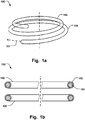
- Fig. 1a shows an annuloplasty implant 100 comprising an inner core 101 of a shape memory material, an outer covering 102 arranged radially outside said inner core material to cover at least part of said inner core, wherein the outer covering is resilient to conform to the inner core during movement of the shape memory material.
- the outer covering readily follows the movement of the inner core material, such when stretching the ring during delivery in a catheter, and subsequently, returning to the ring shape after released from the confinement of the catheter.
- the outer covering comprises a first material having surface properties to promote endothelialization.
- the first material may be a metal alloy.
- the material of the inner core material can thus be optimized for providing the desired shape memory properties, such as fast recovery to the predefined implanted shape, while the outer covering 102 is customized to promote the endothelialization process.
- This dual functionality removes the issue of having to compromise between the most desired shape memory properties in the initial stage and the long term characteristics desired to accelerate endothelialization and minimize the risk of late embolism.
- the latter functionality thus needs not to be dictated by the core material, which may not provide for the most desired surface characteristics for endothelialization.
- the shape memory effect would have been impeded if the annuloplasty implant would have been tailored for endothelialization purely. Thus a synergetic effect is obtained by having such customized core material and covering.
- the core material may comprise a single wire or filament.
- the core material may also comprise a plurality of wires or filaments.
- the number of wires or filaments may be varied as desired in order to provide the desired properties of the core material, such as the desired flexibility, shape memory effects, or cross-sectional dimension, that is preferred for the procedure.
- the annuloplasty implant may be both a helix or coil shape as seen in Fig. 1a and 4 , or a closed ring 200 as seen in Fig. 5 . Any type of ring, such as open ring or C-shaped ring is also possible.
- Fig. 1b shows a cross-section of the implant 100 for illustrating the inner core 101 and the outer covering 102.
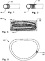
- the outer covering 102 comprises a spiral 103 wound around the inner core 101, as illustrated in the detailed view of Fig. 2 , and in Fig. 4 .
- the spiral may easily conform to the shape of the core material and follow movement thereof without affecting shape memory properties.
- the spiral can provide for an increased surface roughness that ease the formation of endothelia cells over the surface and reduces the time for the endothelialization process and tissue overgrowth.
- the surface of the outer covering is sufficiently smooth, with a low friction coefficient, so that the implant slides into place easily and minimizes any interference with the tissue.
- the coil comprises a wire having a flattened cross-sectional profile, that can provide such smooth surface.
- the outer covering may comprise a mesh or braiding 104 of strands, as illustrated in the detailed view of Fig. 3 .
- the mesh may also easily conform to the shape of the core material and follow movement thereof without affecting shape memory properties.
- the mesh can provide for an increased surface roughness that ease the formation of endothelia cells over the surface and reduces the time for the endothelialization process and tissue overgrowth.
- the implant 100, 200 may have any combination of spirals and mesh on different portions of the implant.
- Fig. 5 illustrates just a portion of the implant 200 having a covering 103, 104, for sake of clarity of presentation only.
- the outer covering 102 may have a predefined surface porosity or roughness to start endothealialization within a set time period. Thus it is possible to customize the surface properties to attain the desired endothealialization process, to minimize embolism.
- the outer covering 102 may cover substantially the entire core 101 in the longitudinal direction 107 of the implant 100, 200. This may provide for optimized endothealialization across the entire length of the implant.
- the covering may also have different properties on different parts of the implant 100, 200. In case having a coil shaped ring the ring placed towards the atrium or the ventricle may have different properties than the other ring.
- the implant may comprise a catheter deliverable ring 100, wherein said ring has an elongated delivery configuration for advancement in a catheter and an implanted shape assuming a predefined configuration of said shape memory material for positioning at a heart valve annulus.
- the ring in the implanted shape may comprise a first 105 and second 106 support members arranged in a coiled configuration, and being adapted to be arranged on opposite sides of native heart valve leaflets to pinch said leaflets.
- the outer covering may cover the first and second support members.
- the covering may only be provided at one of the rings, or have different properties for the rings as mentioned above.
- the annuloplasty implant 100, 200 may comprise a recess 108 along a portion of the implant to reduce the cross-sectional area thereof at said recess, as illustrated in Figs. 6 and 7 .
- Two portions 109, 110 of the implant 100, 200 may thus be joined at said recess 108 and be flexible with respect to eachother by a bending motion at the recess 108.
- the recess can thus serve to increase the flexibility of the implant, at defined locations where more movement is desired.
- the recess is provided in the inner core 101 of the shape memory material.
- the two portions 109, 110 may also have a predefined breaking point at the recess 108.
- a predefined breaking point at the recess 108.
- the annuloplasty implant may comprise a plurality of said recesses 108, 108', along a longitudinal direction 107 of said implant, as seen in Fig. 6 .
- a plurality of flexing or breaking points may thus be provided as desired where flexing, or possibly breaking, is preferred.
- the covering may be arranged over said recess.
- the first material may comprise a first metal alloy that is bio compatible, such as stainless steel, NiTinol, or any other metal alloy that is suitable for formation of endothelia.
- the metal alloy covering over the inner core provides for reduced friction against a delivery catheter, compared to e.g. surfaces being more porous and/or having higher friction coefficients such as textile coverings. It is also conceivable to have a polymer covering that also has a very low friction coefficient, similar to that of the surface of a metal alloy. This may thus facilitate delivery of the implant, and allowing a more controlled delivery, since the implant moves more easily through the delivery catheter.
- Having a metal alloy as outer covering provides also for a compact implant with a minimized cross-sectional dimension, while allowing for the optimization of the shape memory properties of the core material simultaneous as having the optimized properties of the covering with respect to endothelialization, as well as the low-friction properties described in the foregoing.
- the compact cross-sectional dimension allows for using a thinner catheter, that can be advantageous in some procedures, and/or facilitates the simultaneous use of additional instruments that can be inserted in parallel lumens of the catheter during the procedure.
- the covering may comprise any polymer and is not limited to a metal alloy.
- the inner core may comprise a second material such as a second metal alloy, different from said first material or first metal alloy, such as NiTinol, or any other alloy that provides for the desired shape memory effect.
- the inner core may comprise any polymer and is not limited to a metal alloy. Both metal alloys and polymers can be treated during manufacturing to have a desired heat-set shape, which is the shape the implant strives towards when any restraining force is removed, i.e. the relaxed shape, such as when the implant is pushed out of the delivery catheter which forces the implant into an elongated shape. It is also possible that the implant assumes the desired implanted shape by activation of the shape memory function of the material, such as by addition of energy, e.g. heating, electromagnetic energy etc, or by mechanical restructuring of the material.
- annuloplasty implant without a covering according to one example not part of the invention.
- Such annuloplasty implant comprises a shape memory material and a recess 108 along a portion of said implant to reduce the cross-sectional area thereof at said recess, wherein two portions 109, 110 of said implant are joined at said recess and are flexible with respect to eachother by a bending motion at said recess.
Description
- This invention pertains in general to the field of cardiac valve replacement and repair. More particularly the invention relates to an annuloplasty implant, such as an annuloplasty ring or helix, for positioning at the heart valve annulus.
- Diseased mitral and tricuspid valves frequently need replacement or repair. The mitral and tricuspid valve leaflets or supporting chordae may degenerate and weaken or the annulus may dilate leading to valve leak. Mitral and tricuspid valve replacement and repair are frequently performed with aid of an annuloplasty ring, used to reduce the diameter of the annulus, or modify the geometry of the annulus in any other way, or aid as a generally supporting structure during the valve replacement or repair procedure.
- Annuloplasty rings devised for implantation are over time overgrown and encapsulated by tissue. The process of endothelialization, leading to the encapsulation of the implant by tissue, depends on the surface properties of the implant. Incomplete or delayed endothelialization can be a cause of embolism or thrombosis in a later stage after implantation.
- A problem with prior art annuloplasty implants is the compromise between the functionality of the implant during the initial stages, such as during the implantation procedure, and the long term characteristics of the implant, for example with respect to the endothelialization process.
- A further problem of prior art devices is the lack of flexibility of the implant in certain situations, which impedes optimal functioning when implanted in the moving heart, or adaptability to varying anatomies.
- An annuloplasty implant is intended to function for years and years, so it is critical with long term stability. Material fatigue may nevertheless lead to rupture of the material, that may be unexpected and uncontrolled. This entails a higher risk to the patient and it is thus a further problem of prior art devices.
- The above problems may have dire consequences for the patient and the health care system. Patient risk is increased.
- Hence, an improved annuloplasty implant would be advantageous and in particular allowing for improved properties during the initial implantation phase, and long term functioning.
-
US 2010/121433 A1 discloses in the embodiment of Fig. 18 an annuloplasty implant comprising an inner core of a shape memory material and an outer cloth covering formed of a thin strip of material wound helically around the inner core. - Accordingly, embodiments of the present invention preferably seeks to mitigate, alleviate or eliminate one or more deficiencies, disadvantages or issues in the art, such as the above-identified, singly or in any combination by providing a device according to the appended patent claims.
- According to a first aspect an annuloplasty implant is provided comprising an inner core of a shape memory material, an outer covering arranged radially outside said inner core material to cover at least part of said inner core, wherein said outer covering is resilient to conform to said inner core during movement of said shape memory material, wherein said outer covering comprises a first material having surface properties to promote endothelialization.
- According to a second aspect an annuloplasty implant is provided comprising a shape memory material, a recess along a portion of said implant to reduce the cross-sectional area thereof at said recess, wherein two portions of said implant are joined at said recess and are flexible with respect to eachother by a bending motion at said recess.
- Further embodiments of the invention are defined in the dependent claims, wherein features for the second and subsequent aspects of the invention are as for the first aspect mutatis mutandis.
- Some embodiments of the invention provide for improved endothealialization.
- Some embodiments of the invention provide for prevention of late embolism or thrombosis.
- Some embodiments of the invention provides for increased safety in case of material fatigue and rupture.
- Some embodiments of the invention provide for a more flexible implant.
- Some embodiments of the invention provide for a low-profile implant.
- Some embodiments of the invention provide for facilitated delivery of the implant to the target site.
- Some embodiments of the invention provide for minimized friction of the implant against the delivery catheter.
- It should be emphasized that the term "comprises/comprising" when used in this specification is taken to specify the presence of stated features, integers, steps or components but does not preclude the presence or addition of one or more other features, integers, steps, components or groups thereof.
- These and other aspects, features and advantages of which embodiments of the invention are capable of will be apparent and elucidated from the following description of embodiments of the present invention, reference being made to the accompanying drawings, in which
-
Fig. 1a is an illustration of an annuloplasty implant according to an embodiment of the invention; -
Fig. 1b is an illustration of the annuloplasty implant inFig. 1a in a cross-sectional view, according to an embodiment of the invention; -
Fig. 2 is an illustration of an annuloplasty implant according to an embodiment of the invention in a detail view fromFig. 1b ; -
Fig. 3 is an illustration of an annuloplasty implant in a detail view fromFig. 1b ; -
Fig. 4 is an illustration of an annuloplasty implant, in a helix or coil shape, according to an embodiment of the invention; -
Fig. 5 is an illustration of an annuloplasty implant according to an embodiment of the invention; -
Fig. 6 is an illustration of an annuloplasty implant, in a detailed view, according to an embodiment of the invention; -
Fig. 7 is an illustration of an annuloplasty implant in a perspective view according to an embodiment of the invention; -
Fig. 8 is an illustration of an annuloplasty implant, in a detailed view, according to an embodiment of the invention; and -
Fig. 9 is an illustration of an annuloplasty implant, in a detailed view. - Specific embodiments of the invention will now be described with reference to the accompanying drawings. This invention may, however, be embodied in many different forms and should not be construed as limited to the embodiments set forth herein; rather, these embodiments are provided so that this disclosure will be thorough and complete, and will fully convey the scope of the invention to those skilled in the art. The terminology used in the detailed description of the embodiments illustrated in the accompanying drawings is not intended to be limiting of the invention. In the drawings, like numbers refer to like elements.
- The following description focuses on an embodiment of the present invention applicable to cardiac valve implants such as annuloplasty rings. However, it will be appreciated that the invention is not limited to this application but may be applied to many other annuloplasty implants and cardiac valve implants including for example replacement valves, and other medical implantable devices.
-
Fig. 1a shows anannuloplasty implant 100 comprising aninner core 101 of a shape memory material, anouter covering 102 arranged radially outside said inner core material to cover at least part of said inner core, wherein the outer covering is resilient to conform to the inner core during movement of the shape memory material. Thus, the outer covering readily follows the movement of the inner core material, such when stretching the ring during delivery in a catheter, and subsequently, returning to the ring shape after released from the confinement of the catheter. The outer covering comprises a first material having surface properties to promote endothelialization. The first material may be a metal alloy. The material of the inner core material can thus be optimized for providing the desired shape memory properties, such as fast recovery to the predefined implanted shape, while theouter covering 102 is customized to promote the endothelialization process. This dual functionality removes the issue of having to compromise between the most desired shape memory properties in the initial stage and the long term characteristics desired to accelerate endothelialization and minimize the risk of late embolism. The latter functionality thus needs not to be dictated by the core material, which may not provide for the most desired surface characteristics for endothelialization. Similarly, the shape memory effect would have been impeded if the annuloplasty implant would have been tailored for endothelialization purely. Thus a synergetic effect is obtained by having such customized core material and covering. The core material may comprise a single wire or filament. The core material may also comprise a plurality of wires or filaments. The number of wires or filaments may be varied as desired in order to provide the desired properties of the core material, such as the desired flexibility, shape memory effects, or cross-sectional dimension, that is preferred for the procedure. The annuloplasty implant may be both a helix or coil shape as seen inFig. 1a and4 , or aclosed ring 200 as seen inFig. 5 . Any type of ring, such as open ring or C-shaped ring is also possible.Fig. 1b shows a cross-section of theimplant 100 for illustrating theinner core 101 and theouter covering 102. - The
outer covering 102 comprises aspiral 103 wound around theinner core 101, as illustrated in the detailed view ofFig. 2 , and inFig. 4 . The spiral may easily conform to the shape of the core material and follow movement thereof without affecting shape memory properties. The spiral can provide for an increased surface roughness that ease the formation of endothelia cells over the surface and reduces the time for the endothelialization process and tissue overgrowth. At the same time, the surface of the outer covering is sufficiently smooth, with a low friction coefficient, so that the implant slides into place easily and minimizes any interference with the tissue. As can be seen inFig. 4 , the coil comprises a wire having a flattened cross-sectional profile, that can provide such smooth surface. - In an example not part of the present invention, the outer covering may comprise a mesh or braiding 104 of strands, as illustrated in the detailed view of
Fig. 3 . The mesh may also easily conform to the shape of the core material and follow movement thereof without affecting shape memory properties. The mesh can provide for an increased surface roughness that ease the formation of endothelia cells over the surface and reduces the time for the endothelialization process and tissue overgrowth. Theimplant Fig. 5 illustrates just a portion of theimplant 200 having a covering 103, 104, for sake of clarity of presentation only. - The
outer covering 102 may have a predefined surface porosity or roughness to start endothealialization within a set time period. Thus it is possible to customize the surface properties to attain the desired endothealialization process, to minimize embolism. - The
outer covering 102 may cover substantially theentire core 101 in thelongitudinal direction 107 of theimplant implant - The implant may comprise a catheter
deliverable ring 100, wherein said ring has an elongated delivery configuration for advancement in a catheter and an implanted shape assuming a predefined configuration of said shape memory material for positioning at a heart valve annulus. Thus the ring in the implanted shape may comprise a first 105 and second 106 support members arranged in a coiled configuration, and being adapted to be arranged on opposite sides of native heart valve leaflets to pinch said leaflets. - The outer covering may cover the first and second support members. Alternatively, the covering may only be provided at one of the rings, or have different properties for the rings as mentioned above.
- The
annuloplasty implant recess 108 along a portion of the implant to reduce the cross-sectional area thereof at said recess, as illustrated inFigs. 6 and 7 . - Two
portions implant recess 108 and be flexible with respect to eachother by a bending motion at therecess 108. The recess can thus serve to increase the flexibility of the implant, at defined locations where more movement is desired. The recess is provided in theinner core 101 of the shape memory material. - The two
portions recess 108. Thus since the amount of material is less at the reduced cross-section of the implant it is possible to define preferred breaking points of the implant, to avoid random breaking in case of material fatigue occurs after a long time. The location of the breaking point can thus be positioned to not cause any damage to the patient. Further, even if the core material is not broken, the material properties may change over time, e.g. becoming less flexible due to material hardening, and the recess will thus still provide flexibility to the implant. - The annuloplasty implant may comprise a plurality of said
recesses 108, 108', along alongitudinal direction 107 of said implant, as seen inFig. 6 . A plurality of flexing or breaking points may thus be provided as desired where flexing, or possibly breaking, is preferred. - The covering may be arranged over said recess. In case of having a covering 102, there will also be an additional increase in safety since the covering will prevent any broken parts to be dislodged into the patient.
- The first material may comprise a first metal alloy that is bio compatible, such as stainless steel, NiTinol, or any other metal alloy that is suitable for formation of endothelia. In addition of the advantageous properties of such metal alloy for the endothelialization process, the metal alloy covering over the inner core provides for reduced friction against a delivery catheter, compared to e.g. surfaces being more porous and/or having higher friction coefficients such as textile coverings. It is also conceivable to have a polymer covering that also has a very low friction coefficient, similar to that of the surface of a metal alloy. This may thus facilitate delivery of the implant, and allowing a more controlled delivery, since the implant moves more easily through the delivery catheter. It is thus possible to optimize the outer covering for providing advantageous formation of endothelia, while at the same time reducing friction, and further having the inner core optimized for the desired shape-memory properties as described above. The effect of having reduced friction can also be advantageously combined with having the
recess 108, 108', in the core material, providing for the advantageous effects as described above with respect to therecess 108, 108'. - Having a metal alloy as outer covering provides also for a compact implant with a minimized cross-sectional dimension, while allowing for the optimization of the shape memory properties of the core material simultaneous as having the optimized properties of the covering with respect to endothelialization, as well as the low-friction properties described in the foregoing. The compact cross-sectional dimension allows for using a thinner catheter, that can be advantageous in some procedures, and/or facilitates the simultaneous use of additional instruments that can be inserted in parallel lumens of the catheter during the procedure.
- The covering may comprise any polymer and is not limited to a metal alloy.
- The inner core may comprise a second material such as a second metal alloy, different from said first material or first metal alloy, such as NiTinol, or any other alloy that provides for the desired shape memory effect. The inner core may comprise any polymer and is not limited to a metal alloy. Both metal alloys and polymers can be treated during manufacturing to have a desired heat-set shape, which is the shape the implant strives towards when any restraining force is removed, i.e. the relaxed shape, such as when the implant is pushed out of the delivery catheter which forces the implant into an elongated shape. It is also possible that the implant assumes the desired implanted shape by activation of the shape memory function of the material, such as by addition of energy, e.g. heating, electromagnetic energy etc, or by mechanical restructuring of the material.
- It is also disclosed an annuloplasty implant without a covering according to one example not part of the invention. Such annuloplasty implant comprises a shape memory material and a
recess 108 along a portion of said implant to reduce the cross-sectional area thereof at said recess, wherein twoportions - The present invention has been described above with reference to specific embodiments. However, other embodiments than the above described are equally possible within the scope of the invention. The different features and steps of the invention may be combined in other combinations than those described. The scope of the invention is only limited by the appended patent claims. More generally, those skilled in the art will readily appreciate that all parameters, dimensions, materials, and configurations described herein are meant to be exemplary and that the actual parameters, dimensions, materials, and/or configurations will depend upon the specific application or applications for which the teachings of the present invention is/are used.
Claims (13)
- An annuloplasty implant (100, 200) comprising
an inner core (101) of a shape memory material,
an outer covering (102) arranged radially outside said inner core material to cover at least part of said inner core, wherein said outer covering is resilient to conform to said inner core during movement of said shape memory material, wherein said outer covering is formed of a first material having surface properties to promote endothelialization, wherein said outer covering is a spiral (103) wound around said inner core, characterized in that said spiral is formed of a wire having a flattened cross-sectional profile. - Annuloplasty implant according to claim 1, wherein said outer covering comprises a mesh or braiding (104) of strands.
- Annuloplasty implant according to any of claims 1-2, wherein said implant comprises a catheter deliverable ring (100), wherein said ring has an elongated delivery configuration for advancement in a catheter and an implanted shape assuming a predefined configuration of said shape memory material for positioning at a heart valve annulus.
- Annuloplasty implant according to claim 3, wherein said ring in the implanted shape comprises a first (105) and second (106) support members arranged in a coiled configuration, and being adapted to be arranged on opposite sides of native heart valve leaflets to pinch said leaflets.
- Annuloplasty implant according to claim 4, wherein said outer covering covers substantially the entire core in a longitudinal direction (107) of the implant.
- Annuloplasty implant according to claim 4, wherein said outer covering covers the first and second support members.
- Annuloplasty implant according to any of claims 1-6, comprising a recess (108) along a portion of said implant to reduce the cross-sectional area thereof at said recess.
- Annuloplasty implant according to claim 7, wherein two portions (109, 110) of said implant are joined at said recess and are flexible with respect to eachother by a bending motion at said recess.
- Annuloplasty implant according to claim 8, wherein said two portions has a predefined breaking point at said recess.
- Annuloplasty implant according to any of claims 7-9, comprising a plurality of said recesses (108,108') along a longitudinal direction (107) of said implant.
- Annuloplasty implant according to any of claims 6-10, wherein said covering is arranged over said recess.
- Annuloplasty implant according to any of claims 1-11, wherein said first material comprises a first metal alloy.
- Annuloplasty implant according to any of claims 1-12, wherein said inner core comprises a second material, different from said first material, and wherein said second material comprises a second metal alloy such as NiTinol.
Applications Claiming Priority (2)
| Application Number | Priority Date | Filing Date | Title |
|---|---|---|---|
| US201462047077P | 2014-09-08 | 2014-09-08 | |
| PCT/EP2015/070464 WO2016038017A1 (en) | 2014-09-08 | 2015-09-08 | Annuloplasty implant |
Publications (2)
| Publication Number | Publication Date |
|---|---|
| EP3191025A1 EP3191025A1 (en) | 2017-07-19 |
| EP3191025B1 true EP3191025B1 (en) | 2020-12-09 |
Family
ID=54056219
Family Applications (1)
| Application Number | Title | Priority Date | Filing Date |
|---|---|---|---|
| EP15757527.5A Active EP3191025B1 (en) | 2014-09-08 | 2015-09-08 | Annuloplasty implant |
Country Status (8)
| Country | Link |
|---|---|
| US (2) | US20170273788A1 (en) |
| EP (1) | EP3191025B1 (en) |
| JP (2) | JP2017527373A (en) |
| CN (1) | CN106714732A (en) |
| BR (1) | BR112017004430A2 (en) |
| CA (1) | CA2960422C (en) |
| MX (1) | MX2017002885A (en) |
| WO (1) | WO2016038017A1 (en) |
Families Citing this family (53)
| Publication number | Priority date | Publication date | Assignee | Title |
|---|---|---|---|---|
| US8323335B2 (en) | 2008-06-20 | 2012-12-04 | Edwards Lifesciences Corporation | Retaining mechanisms for prosthetic valves and methods for using |
| US8398708B2 (en) | 2010-03-05 | 2013-03-19 | Edwards Lifesciences Corporation | Retaining mechanisms for prosthetic valves |
| US8579964B2 (en) | 2010-05-05 | 2013-11-12 | Neovasc Inc. | Transcatheter mitral valve prosthesis |
| US8657872B2 (en) | 2010-07-19 | 2014-02-25 | Jacques Seguin | Cardiac valve repair system and methods of use |
| US9326853B2 (en) | 2010-07-23 | 2016-05-03 | Edwards Lifesciences Corporation | Retaining mechanisms for prosthetic valves |
| US9554897B2 (en) | 2011-04-28 | 2017-01-31 | Neovasc Tiara Inc. | Methods and apparatus for engaging a valve prosthesis with tissue |
| US9308087B2 (en) | 2011-04-28 | 2016-04-12 | Neovasc Tiara Inc. | Sequentially deployed transcatheter mitral valve prosthesis |
| US9078747B2 (en) | 2011-12-21 | 2015-07-14 | Edwards Lifesciences Corporation | Anchoring device for replacing or repairing a heart valve |
| WO2013114214A2 (en) | 2012-01-31 | 2013-08-08 | Orford Holdings Sa | Mitral valve docking devices, systems and methods |
| US9345573B2 (en) | 2012-05-30 | 2016-05-24 | Neovasc Tiara Inc. | Methods and apparatus for loading a prosthesis onto a delivery system |
| US9572665B2 (en) | 2013-04-04 | 2017-02-21 | Neovasc Tiara Inc. | Methods and apparatus for delivering a prosthetic valve to a beating heart |
| CN105682610B (en) | 2013-08-12 | 2017-11-03 | 米特拉尔维尔福科技有限责任公司 | Apparatus and method for being implanted into replacement heart valve |
| US10226330B2 (en) | 2013-08-14 | 2019-03-12 | Mitral Valve Technologies Sarl | Replacement heart valve apparatus and methods |
| US10195028B2 (en) | 2013-09-10 | 2019-02-05 | Edwards Lifesciences Corporation | Magnetic retaining mechanisms for prosthetic valves |
| US9622863B2 (en) | 2013-11-22 | 2017-04-18 | Edwards Lifesciences Corporation | Aortic insufficiency repair device and method |
| CN106572905B (en) | 2014-02-20 | 2019-11-05 | 米特拉尔维尔福科技有限责任公司 | It is used to support the anchoring piece curled up, heart valve prosthesis and deployment device of heart valve prosthesis |
| US10052199B2 (en) | 2014-02-21 | 2018-08-21 | Mitral Valve Technologies Sarl | Devices, systems and methods for delivering a prosthetic mitral valve and anchoring device |
| US10016272B2 (en) | 2014-09-12 | 2018-07-10 | Mitral Valve Technologies Sarl | Mitral repair and replacement devices and methods |
| US10231834B2 (en) | 2015-02-09 | 2019-03-19 | Edwards Lifesciences Corporation | Low profile transseptal catheter and implant system for minimally invasive valve procedure |
| US10039637B2 (en) | 2015-02-11 | 2018-08-07 | Edwards Lifesciences Corporation | Heart valve docking devices and implanting methods |
| US11833034B2 (en) | 2016-01-13 | 2023-12-05 | Shifamed Holdings, Llc | Prosthetic cardiac valve devices, systems, and methods |
| WO2017127939A1 (en) | 2016-01-29 | 2017-08-03 | Neovasc Tiara Inc. | Prosthetic valve for avoiding obstruction of outflow |
| US10363130B2 (en) | 2016-02-05 | 2019-07-30 | Edwards Lifesciences Corporation | Devices and systems for docking a heart valve |
| US10828150B2 (en) | 2016-07-08 | 2020-11-10 | Edwards Lifesciences Corporation | Docking station for heart valve prosthesis |
| US10722359B2 (en) | 2016-08-26 | 2020-07-28 | Edwards Lifesciences Corporation | Heart valve docking devices and systems |
| CR20190069A (en) | 2016-08-26 | 2019-05-14 | Edwards Lifesciences Corp | Heart valve docking coils and systems |
| US10357361B2 (en) | 2016-09-15 | 2019-07-23 | Edwards Lifesciences Corporation | Heart valve pinch devices and delivery systems |
| CN113893064A (en) | 2016-11-21 | 2022-01-07 | 内奥瓦斯克迪亚拉公司 | Methods and systems for rapid retrieval of transcatheter heart valve delivery systems |
| JP7440263B2 (en) | 2016-12-16 | 2024-02-28 | エドワーズ ライフサイエンシーズ コーポレイション | Deployment systems, tools, and methods for delivering anchoring devices for prosthetic valves |
| US10813749B2 (en) | 2016-12-20 | 2020-10-27 | Edwards Lifesciences Corporation | Docking device made with 3D woven fabric |
| SG10202109534TA (en) | 2016-12-20 | 2021-10-28 | Edwards Lifesciences Corp | Systems and mechanisms for deploying a docking device for a replacement heart valve |
| US11013600B2 (en) | 2017-01-23 | 2021-05-25 | Edwards Lifesciences Corporation | Covered prosthetic heart valve |
| US11654023B2 (en) | 2017-01-23 | 2023-05-23 | Edwards Lifesciences Corporation | Covered prosthetic heart valve |
| US11185406B2 (en) | 2017-01-23 | 2021-11-30 | Edwards Lifesciences Corporation | Covered prosthetic heart valve |
| USD867595S1 (en) | 2017-02-01 | 2019-11-19 | Edwards Lifesciences Corporation | Stent |
| US10842619B2 (en) | 2017-05-12 | 2020-11-24 | Edwards Lifesciences Corporation | Prosthetic heart valve docking assembly |
| EP3406225B1 (en) | 2017-05-23 | 2023-04-26 | HVR Cardio Oy | Annuloplasty implant |
| CN110996853B (en) | 2017-06-30 | 2023-01-10 | 爱德华兹生命科学公司 | Docking station for transcatheter valve |
| EP3644902A4 (en) | 2017-06-30 | 2020-06-10 | Edwards Lifesciences Corporation | Lock and release mechanisms for trans-catheter implantable devices |
| USD890333S1 (en) | 2017-08-21 | 2020-07-14 | Edwards Lifesciences Corporation | Heart valve docking coil |
| EP3672530A4 (en) | 2017-08-25 | 2021-04-14 | Neovasc Tiara Inc. | Sequentially deployed transcatheter mitral valve prosthesis |
| EP3796875B1 (en) * | 2018-05-21 | 2022-12-21 | Medtentia International Ltd Oy | Annuloplasty device |
| CN112437651B (en) * | 2018-07-30 | 2024-01-16 | 爱德华兹生命科学公司 | Minimally Invasive Low Strain Annuloplasty Ring |
| CA3115270A1 (en) | 2018-10-05 | 2020-04-09 | Shifamed Holdings, Llc | Prosthetic cardiac valve devices, systems, and methods |
| US11737872B2 (en) | 2018-11-08 | 2023-08-29 | Neovasc Tiara Inc. | Ventricular deployment of a transcatheter mitral valve prosthesis |
| WO2020168227A1 (en) * | 2019-02-15 | 2020-08-20 | The Trustees Of Columbia University In The City Of New York | Medical apparatus for in-heart valve surgery |
| US11471282B2 (en) | 2019-03-19 | 2022-10-18 | Shifamed Holdings, Llc | Prosthetic cardiac valve devices, systems, and methods |
| JP7438236B2 (en) | 2019-04-01 | 2024-02-26 | ニオバスク ティアラ インコーポレイテッド | Controllably deployable prosthetic valve |
| EP3952792A4 (en) | 2019-04-10 | 2023-01-04 | Neovasc Tiara Inc. | Prosthetic valve with natural blood flow |
| US11779742B2 (en) | 2019-05-20 | 2023-10-10 | Neovasc Tiara Inc. | Introducer with hemostasis mechanism |
| AU2020295566B2 (en) | 2019-06-20 | 2023-07-20 | Neovasc Tiara Inc. | Low profile prosthetic mitral valve |
| EP3996630A1 (en) * | 2019-07-11 | 2022-05-18 | Medtentia International Ltd Oy | Annuloplasty device |
| EP3766457A1 (en) * | 2019-07-17 | 2021-01-20 | Medtentia International Ltd Oy | Annuloplasty device |
Citations (1)
| Publication number | Priority date | Publication date | Assignee | Title |
|---|---|---|---|---|
| CN103735337A (en) * | 2013-12-31 | 2014-04-23 | 金仕生物科技(常熟)有限公司 | Artificial heart valve annuloplastic ring |
Family Cites Families (25)
| Publication number | Priority date | Publication date | Assignee | Title |
|---|---|---|---|---|
| US4745919A (en) * | 1985-02-01 | 1988-05-24 | Bundy Mark A | Transluminal lysing system |
| US5628790A (en) * | 1989-07-25 | 1997-05-13 | Smith & Nephew, Inc. | Zirconium oxide zirconium nitride coated valvular annuloplasty rings |
| CN2135346Y (en) * | 1992-09-12 | 1993-06-09 | 中国人民解放军第四军医大学第一附属医院 | Plasticity bicuspid valve shaping ring |
| US6245030B1 (en) * | 1998-03-04 | 2001-06-12 | C. R. Bard, Inc. | Flexible kink resistant, low friction guidewire with formable tip, and method for making same |
| AU2001296442A1 (en) * | 2000-09-29 | 2002-04-08 | Tricardia, L.L.C. | Venous valvuloplasty device |
| DE60225303T2 (en) * | 2001-08-31 | 2009-02-26 | Mitral Interventions, Redwood City | DEVICE FOR A HEART LAPSE REPAIR |
| CN2561368Y (en) * | 2001-11-09 | 2003-07-23 | 上海市胸科医院 | Artificial cardiac valves anjd valve holder |
| US6805710B2 (en) * | 2001-11-13 | 2004-10-19 | Edwards Lifesciences Corporation | Mitral valve annuloplasty ring for molding left ventricle geometry |
| US7452376B2 (en) * | 2004-05-14 | 2008-11-18 | St. Jude Medical, Inc. | Flexible, non-planar annuloplasty rings |
| US20070135913A1 (en) * | 2004-06-29 | 2007-06-14 | Micardia Corporation | Adjustable annuloplasty ring activation system |
| EP2491891A3 (en) * | 2004-10-02 | 2013-03-20 | Endoheart AG | Devices for embolic protection and mitral valve repair |
| CN101340861B (en) * | 2005-02-28 | 2011-08-10 | 梅德坦提亚国际有限公司 | Devices and a kit for improving the function of a heart valve |
| US20060229638A1 (en) * | 2005-03-29 | 2006-10-12 | Abrams Robert M | Articulating retrieval device |
| US20070027533A1 (en) * | 2005-07-28 | 2007-02-01 | Medtronic Vascular, Inc. | Cardiac valve annulus restraining device |
| EP1790318B1 (en) * | 2005-11-16 | 2009-04-22 | Micardia Corporation | Magnetic engagement of catheter to implantable device |
| US8430926B2 (en) * | 2006-08-11 | 2013-04-30 | Japd Consulting Inc. | Annuloplasty with enhanced anchoring to the annulus based on tissue healing |
| US20100121433A1 (en) * | 2007-01-08 | 2010-05-13 | Millipede Llc, A Corporation Of Michigan | Reconfiguring heart features |
| US20100249920A1 (en) * | 2007-01-08 | 2010-09-30 | Millipede Llc | Reconfiguring heart features |
| EP1958598A1 (en) * | 2007-02-16 | 2008-08-20 | Universität Zürich | Growable tubular support implant |
| EP2072027B1 (en) * | 2007-12-21 | 2020-06-17 | Medtentia International Ltd Oy | pre-annuloplasty device and method |
| EP2393449B1 (en) * | 2009-02-06 | 2016-09-07 | St. Jude Medical, Inc. | Support for adjustable annuloplasty ring |
| US10406009B2 (en) * | 2010-09-15 | 2019-09-10 | Abbott Cardiovascular Systems Inc. | Bioabsorbable superficial femoral stent patterns with designed to break links |
| US8932350B2 (en) * | 2010-11-30 | 2015-01-13 | Edwards Lifesciences Corporation | Reduced dehiscence annuloplasty ring |
| AU2012299311B2 (en) * | 2011-08-11 | 2016-03-03 | Tendyne Holdings, Inc. | Improvements for prosthetic valves and related inventions |
| CN202699349U (en) * | 2012-07-05 | 2013-01-30 | 甄文俊 | Heart valve prosthesis forming ring |
-
2015
- 2015-09-08 EP EP15757527.5A patent/EP3191025B1/en active Active
- 2015-09-08 BR BR112017004430A patent/BR112017004430A2/en not_active Application Discontinuation
- 2015-09-08 CN CN201580048268.5A patent/CN106714732A/en active Pending
- 2015-09-08 WO PCT/EP2015/070464 patent/WO2016038017A1/en active Application Filing
- 2015-09-08 CA CA2960422A patent/CA2960422C/en active Active
- 2015-09-08 JP JP2017512909A patent/JP2017527373A/en active Pending
- 2015-09-08 MX MX2017002885A patent/MX2017002885A/en unknown
- 2015-09-08 US US15/509,458 patent/US20170273788A1/en not_active Abandoned
-
2020
- 2020-04-08 JP JP2020069728A patent/JP2020114479A/en active Pending
- 2020-08-06 US US16/986,605 patent/US20200360143A1/en not_active Abandoned
Patent Citations (2)
| Publication number | Priority date | Publication date | Assignee | Title |
|---|---|---|---|---|
| CN103735337A (en) * | 2013-12-31 | 2014-04-23 | 金仕生物科技(常熟)有限公司 | Artificial heart valve annuloplastic ring |
| EP3090703A1 (en) * | 2013-12-31 | 2016-11-09 | Kingstronbio(Changshu) Co., Ltd | Artificial heart valve annuloplasty ring |
Also Published As
| Publication number | Publication date |
|---|---|
| EP3191025A1 (en) | 2017-07-19 |
| MX2017002885A (en) | 2017-09-28 |
| JP2017527373A (en) | 2017-09-21 |
| JP2020114479A (en) | 2020-07-30 |
| CA2960422C (en) | 2023-08-01 |
| CN106714732A (en) | 2017-05-24 |
| BR112017004430A2 (en) | 2017-12-05 |
| US20170273788A1 (en) | 2017-09-28 |
| CA2960422A1 (en) | 2016-03-17 |
| WO2016038017A1 (en) | 2016-03-17 |
| US20200360143A1 (en) | 2020-11-19 |
Similar Documents
| Publication | Publication Date | Title |
|---|---|---|
| US20200360143A1 (en) | Annuloplasty Implant | |
| EP3700467B1 (en) | Annuloplasty implant | |
| CA3011791C (en) | Annuloplasty implant | |
| EP3737336B1 (en) | Annuloplasty device | |
| JP6141420B2 (en) | Implantable device for ameliorating or treating valvular heart disease | |
| JP2017527373A5 (en) | ||
| US6305436B1 (en) | Medical stents for body lumens exhibiting peristaltic motion | |
| EP2082690A1 (en) | Medical device to assist diastolic function and prevent ventricular enlargement | |
| US20140163669A1 (en) | Devices and methods for the replacement of the functioning of heart valves | |
| JP7318163B2 (en) | annuloplasty implant | |
| US20180133012A1 (en) | Implantable device for improving or treating a heart valve insufficiency | |
| EP3998991A1 (en) | Annuloplasty device | |
| US20240016606A1 (en) | Annuloplasty Device | |
| US20220202570A1 (en) | Annuloplasty Device | |
| US9980833B2 (en) | Uniform expandable and collapsible stent | |
| CN110662513B (en) | Delivery system for deploying self-expanding tubes and method of deploying self-expanding tubes | |
| US20170172767A1 (en) | Stents for placement in an anatomical passageway and methods |
Legal Events
| Date | Code | Title | Description |
|---|---|---|---|
| STAA | Information on the status of an ep patent application or granted ep patent |
Free format text: STATUS: THE INTERNATIONAL PUBLICATION HAS BEEN MADE |
|
| PUAI | Public reference made under article 153(3) epc to a published international application that has entered the european phase |
Free format text: ORIGINAL CODE: 0009012 |
|
| STAA | Information on the status of an ep patent application or granted ep patent |
Free format text: STATUS: REQUEST FOR EXAMINATION WAS MADE |
|
| 17P | Request for examination filed |
Effective date: 20170328 |
|
| AK | Designated contracting states |
Kind code of ref document: A1 Designated state(s): AL AT BE BG CH CY CZ DE DK EE ES FI FR GB GR HR HU IE IS IT LI LT LU LV MC MK MT NL NO PL PT RO RS SE SI SK SM TR |
|
| AX | Request for extension of the european patent |
Extension state: BA ME |
|
| DAV | Request for validation of the european patent (deleted) | ||
| DAX | Request for extension of the european patent (deleted) | ||
| STAA | Information on the status of an ep patent application or granted ep patent |
Free format text: STATUS: EXAMINATION IS IN PROGRESS |
|
| 17Q | First examination report despatched |
Effective date: 20200218 |
|
| GRAP | Despatch of communication of intention to grant a patent |
Free format text: ORIGINAL CODE: EPIDOSNIGR1 |
|
| STAA | Information on the status of an ep patent application or granted ep patent |
Free format text: STATUS: GRANT OF PATENT IS INTENDED |
|
| INTG | Intention to grant announced |
Effective date: 20200623 |
|
| GRAS | Grant fee paid |
Free format text: ORIGINAL CODE: EPIDOSNIGR3 |
|
| GRAA | (expected) grant |
Free format text: ORIGINAL CODE: 0009210 |
|
| STAA | Information on the status of an ep patent application or granted ep patent |
Free format text: STATUS: THE PATENT HAS BEEN GRANTED |
|
| AK | Designated contracting states |
Kind code of ref document: B1 Designated state(s): AL AT BE BG CH CY CZ DE DK EE ES FI FR GB GR HR HU IE IS IT LI LT LU LV MC MK MT NL NO PL PT RO RS SE SI SK SM TR |
|
| REG | Reference to a national code |
Ref country code: GB Ref legal event code: FG4D |
|
| REG | Reference to a national code |
Ref country code: AT Ref legal event code: REF Ref document number: 1342600 Country of ref document: AT Kind code of ref document: T Effective date: 20201215 Ref country code: CH Ref legal event code: EP |
|
| REG | Reference to a national code |
Ref country code: DE Ref legal event code: R096 Ref document number: 602015063237 Country of ref document: DE |
|
| REG | Reference to a national code |
Ref country code: IE Ref legal event code: FG4D |
|
| PG25 | Lapsed in a contracting state [announced via postgrant information from national office to epo] |
Ref country code: GR Free format text: LAPSE BECAUSE OF FAILURE TO SUBMIT A TRANSLATION OF THE DESCRIPTION OR TO PAY THE FEE WITHIN THE PRESCRIBED TIME-LIMIT Effective date: 20210310 Ref country code: FI Free format text: LAPSE BECAUSE OF FAILURE TO SUBMIT A TRANSLATION OF THE DESCRIPTION OR TO PAY THE FEE WITHIN THE PRESCRIBED TIME-LIMIT Effective date: 20201209 Ref country code: RS Free format text: LAPSE BECAUSE OF FAILURE TO SUBMIT A TRANSLATION OF THE DESCRIPTION OR TO PAY THE FEE WITHIN THE PRESCRIBED TIME-LIMIT Effective date: 20201209 Ref country code: NO Free format text: LAPSE BECAUSE OF FAILURE TO SUBMIT A TRANSLATION OF THE DESCRIPTION OR TO PAY THE FEE WITHIN THE PRESCRIBED TIME-LIMIT Effective date: 20210309 |
|
| REG | Reference to a national code |
Ref country code: AT Ref legal event code: MK05 Ref document number: 1342600 Country of ref document: AT Kind code of ref document: T Effective date: 20201209 |
|
| PG25 | Lapsed in a contracting state [announced via postgrant information from national office to epo] |
Ref country code: LV Free format text: LAPSE BECAUSE OF FAILURE TO SUBMIT A TRANSLATION OF THE DESCRIPTION OR TO PAY THE FEE WITHIN THE PRESCRIBED TIME-LIMIT Effective date: 20201209 Ref country code: SE Free format text: LAPSE BECAUSE OF FAILURE TO SUBMIT A TRANSLATION OF THE DESCRIPTION OR TO PAY THE FEE WITHIN THE PRESCRIBED TIME-LIMIT Effective date: 20201209 Ref country code: BG Free format text: LAPSE BECAUSE OF FAILURE TO SUBMIT A TRANSLATION OF THE DESCRIPTION OR TO PAY THE FEE WITHIN THE PRESCRIBED TIME-LIMIT Effective date: 20210309 |
|
| REG | Reference to a national code |
Ref country code: NL Ref legal event code: MP Effective date: 20201209 |
|
| PG25 | Lapsed in a contracting state [announced via postgrant information from national office to epo] |
Ref country code: NL Free format text: LAPSE BECAUSE OF FAILURE TO SUBMIT A TRANSLATION OF THE DESCRIPTION OR TO PAY THE FEE WITHIN THE PRESCRIBED TIME-LIMIT Effective date: 20201209 Ref country code: HR Free format text: LAPSE BECAUSE OF FAILURE TO SUBMIT A TRANSLATION OF THE DESCRIPTION OR TO PAY THE FEE WITHIN THE PRESCRIBED TIME-LIMIT Effective date: 20201209 |
|
| REG | Reference to a national code |
Ref country code: LT Ref legal event code: MG9D |
|
| PG25 | Lapsed in a contracting state [announced via postgrant information from national office to epo] |
Ref country code: LT Free format text: LAPSE BECAUSE OF FAILURE TO SUBMIT A TRANSLATION OF THE DESCRIPTION OR TO PAY THE FEE WITHIN THE PRESCRIBED TIME-LIMIT Effective date: 20201209 Ref country code: PT Free format text: LAPSE BECAUSE OF FAILURE TO SUBMIT A TRANSLATION OF THE DESCRIPTION OR TO PAY THE FEE WITHIN THE PRESCRIBED TIME-LIMIT Effective date: 20210409 Ref country code: RO Free format text: LAPSE BECAUSE OF FAILURE TO SUBMIT A TRANSLATION OF THE DESCRIPTION OR TO PAY THE FEE WITHIN THE PRESCRIBED TIME-LIMIT Effective date: 20201209 Ref country code: SK Free format text: LAPSE BECAUSE OF FAILURE TO SUBMIT A TRANSLATION OF THE DESCRIPTION OR TO PAY THE FEE WITHIN THE PRESCRIBED TIME-LIMIT Effective date: 20201209 Ref country code: SM Free format text: LAPSE BECAUSE OF FAILURE TO SUBMIT A TRANSLATION OF THE DESCRIPTION OR TO PAY THE FEE WITHIN THE PRESCRIBED TIME-LIMIT Effective date: 20201209 Ref country code: EE Free format text: LAPSE BECAUSE OF FAILURE TO SUBMIT A TRANSLATION OF THE DESCRIPTION OR TO PAY THE FEE WITHIN THE PRESCRIBED TIME-LIMIT Effective date: 20201209 Ref country code: CZ Free format text: LAPSE BECAUSE OF FAILURE TO SUBMIT A TRANSLATION OF THE DESCRIPTION OR TO PAY THE FEE WITHIN THE PRESCRIBED TIME-LIMIT Effective date: 20201209 |
|
| PG25 | Lapsed in a contracting state [announced via postgrant information from national office to epo] |
Ref country code: PL Free format text: LAPSE BECAUSE OF FAILURE TO SUBMIT A TRANSLATION OF THE DESCRIPTION OR TO PAY THE FEE WITHIN THE PRESCRIBED TIME-LIMIT Effective date: 20201209 Ref country code: AT Free format text: LAPSE BECAUSE OF FAILURE TO SUBMIT A TRANSLATION OF THE DESCRIPTION OR TO PAY THE FEE WITHIN THE PRESCRIBED TIME-LIMIT Effective date: 20201209 |
|
| REG | Reference to a national code |
Ref country code: DE Ref legal event code: R097 Ref document number: 602015063237 Country of ref document: DE |
|
| PG25 | Lapsed in a contracting state [announced via postgrant information from national office to epo] |
Ref country code: IS Free format text: LAPSE BECAUSE OF FAILURE TO SUBMIT A TRANSLATION OF THE DESCRIPTION OR TO PAY THE FEE WITHIN THE PRESCRIBED TIME-LIMIT Effective date: 20210409 |
|
| PLBE | No opposition filed within time limit |
Free format text: ORIGINAL CODE: 0009261 |
|
| STAA | Information on the status of an ep patent application or granted ep patent |
Free format text: STATUS: NO OPPOSITION FILED WITHIN TIME LIMIT |
|
| PG25 | Lapsed in a contracting state [announced via postgrant information from national office to epo] |
Ref country code: IT Free format text: LAPSE BECAUSE OF FAILURE TO SUBMIT A TRANSLATION OF THE DESCRIPTION OR TO PAY THE FEE WITHIN THE PRESCRIBED TIME-LIMIT Effective date: 20201209 Ref country code: AL Free format text: LAPSE BECAUSE OF FAILURE TO SUBMIT A TRANSLATION OF THE DESCRIPTION OR TO PAY THE FEE WITHIN THE PRESCRIBED TIME-LIMIT Effective date: 20201209 |
|
| 26N | No opposition filed |
Effective date: 20210910 |
|
| PG25 | Lapsed in a contracting state [announced via postgrant information from national office to epo] |
Ref country code: DK Free format text: LAPSE BECAUSE OF FAILURE TO SUBMIT A TRANSLATION OF THE DESCRIPTION OR TO PAY THE FEE WITHIN THE PRESCRIBED TIME-LIMIT Effective date: 20201209 Ref country code: SI Free format text: LAPSE BECAUSE OF FAILURE TO SUBMIT A TRANSLATION OF THE DESCRIPTION OR TO PAY THE FEE WITHIN THE PRESCRIBED TIME-LIMIT Effective date: 20201209 |
|
| PG25 | Lapsed in a contracting state [announced via postgrant information from national office to epo] |
Ref country code: ES Free format text: LAPSE BECAUSE OF FAILURE TO SUBMIT A TRANSLATION OF THE DESCRIPTION OR TO PAY THE FEE WITHIN THE PRESCRIBED TIME-LIMIT Effective date: 20201209 |
|
| REG | Reference to a national code |
Ref country code: CH Ref legal event code: PL |
|
| REG | Reference to a national code |
Ref country code: BE Ref legal event code: MM Effective date: 20210930 |
|
| GBPC | Gb: european patent ceased through non-payment of renewal fee |
Effective date: 20210908 |
|
| PG25 | Lapsed in a contracting state [announced via postgrant information from national office to epo] |
Ref country code: IS Free format text: LAPSE BECAUSE OF FAILURE TO SUBMIT A TRANSLATION OF THE DESCRIPTION OR TO PAY THE FEE WITHIN THE PRESCRIBED TIME-LIMIT Effective date: 20210409 Ref country code: MC Free format text: LAPSE BECAUSE OF FAILURE TO SUBMIT A TRANSLATION OF THE DESCRIPTION OR TO PAY THE FEE WITHIN THE PRESCRIBED TIME-LIMIT Effective date: 20201209 |
|
| PG25 | Lapsed in a contracting state [announced via postgrant information from national office to epo] |
Ref country code: LU Free format text: LAPSE BECAUSE OF NON-PAYMENT OF DUE FEES Effective date: 20210908 Ref country code: IE Free format text: LAPSE BECAUSE OF NON-PAYMENT OF DUE FEES Effective date: 20210908 Ref country code: GB Free format text: LAPSE BECAUSE OF NON-PAYMENT OF DUE FEES Effective date: 20210908 Ref country code: FR Free format text: LAPSE BECAUSE OF NON-PAYMENT OF DUE FEES Effective date: 20210930 Ref country code: BE Free format text: LAPSE BECAUSE OF NON-PAYMENT OF DUE FEES Effective date: 20210930 |
|
| PG25 | Lapsed in a contracting state [announced via postgrant information from national office to epo] |
Ref country code: LI Free format text: LAPSE BECAUSE OF NON-PAYMENT OF DUE FEES Effective date: 20210930 Ref country code: CH Free format text: LAPSE BECAUSE OF NON-PAYMENT OF DUE FEES Effective date: 20210930 |
|
| PGFP | Annual fee paid to national office [announced via postgrant information from national office to epo] |
Ref country code: DE Payment date: 20220919 Year of fee payment: 8 |
|
| REG | Reference to a national code |
Ref country code: DE Ref legal event code: R081 Ref document number: 602015063237 Country of ref document: DE Owner name: HVR CARDIO OY, FI Free format text: FORMER OWNER: MEDTENTIA INTERNATIONAL LTD OY, ESPOO, FI |
|
| PG25 | Lapsed in a contracting state [announced via postgrant information from national office to epo] |
Ref country code: HU Free format text: LAPSE BECAUSE OF FAILURE TO SUBMIT A TRANSLATION OF THE DESCRIPTION OR TO PAY THE FEE WITHIN THE PRESCRIBED TIME-LIMIT; INVALID AB INITIO Effective date: 20150908 |
|
| P01 | Opt-out of the competence of the unified patent court (upc) registered |
Effective date: 20230428 |
|
| PG25 | Lapsed in a contracting state [announced via postgrant information from national office to epo] |
Ref country code: CY Free format text: LAPSE BECAUSE OF FAILURE TO SUBMIT A TRANSLATION OF THE DESCRIPTION OR TO PAY THE FEE WITHIN THE PRESCRIBED TIME-LIMIT Effective date: 20201209 |