EP3191019B1 - Padded transosseous suture - Google Patents
Padded transosseous suture Download PDFInfo
- Publication number
- EP3191019B1 EP3191019B1 EP15777741.8A EP15777741A EP3191019B1 EP 3191019 B1 EP3191019 B1 EP 3191019B1 EP 15777741 A EP15777741 A EP 15777741A EP 3191019 B1 EP3191019 B1 EP 3191019B1
- Authority
- EP
- European Patent Office
- Prior art keywords
- sleeve
- flexible
- generally cylindrical
- suture
- thread
- Prior art date
- Legal status (The legal status is an assumption and is not a legal conclusion. Google has not performed a legal analysis and makes no representation as to the accuracy of the status listed.)
- Not-in-force
Links
- 210000000988 bone and bone Anatomy 0.000 claims description 80
- 238000003780 insertion Methods 0.000 description 20
- 230000037431 insertion Effects 0.000 description 20
- 238000012546 transfer Methods 0.000 description 20
- 238000004904 shortening Methods 0.000 description 19
- 229920000728 polyester Polymers 0.000 description 16
- 238000000034 method Methods 0.000 description 9
- HLXZNVUGXRDIFK-UHFFFAOYSA-N nickel titanium Chemical compound [Ti].[Ti].[Ti].[Ti].[Ti].[Ti].[Ti].[Ti].[Ti].[Ti].[Ti].[Ni].[Ni].[Ni].[Ni].[Ni].[Ni].[Ni].[Ni].[Ni].[Ni].[Ni].[Ni].[Ni].[Ni] HLXZNVUGXRDIFK-UHFFFAOYSA-N 0.000 description 9
- 229910001000 nickel titanium Inorganic materials 0.000 description 9
- 210000002435 tendon Anatomy 0.000 description 9
- 229920000742 Cotton Polymers 0.000 description 8
- 239000004677 Nylon Substances 0.000 description 8
- 229920001778 nylon Polymers 0.000 description 8
- 238000002513 implantation Methods 0.000 description 5
- 238000011065 in-situ storage Methods 0.000 description 5
- 0 CC(CC1)CC2C1*C*C2 Chemical compound CC(CC1)CC2C1*C*C2 0.000 description 4
- 239000000463 material Substances 0.000 description 3
- 230000001681 protective effect Effects 0.000 description 3
- 239000004744 fabric Substances 0.000 description 2
- 238000012986 modification Methods 0.000 description 2
- 230000004048 modification Effects 0.000 description 2
- 239000007787 solid Substances 0.000 description 2
- 241000293001 Oxytropis besseyi Species 0.000 description 1
- 241000287107 Passer Species 0.000 description 1
- 238000013459 approach Methods 0.000 description 1
- 239000000560 biocompatible material Substances 0.000 description 1
- 238000005520 cutting process Methods 0.000 description 1
- 230000003247 decreasing effect Effects 0.000 description 1
- 230000001419 dependent effect Effects 0.000 description 1
- 238000006073 displacement reaction Methods 0.000 description 1
- 230000009977 dual effect Effects 0.000 description 1
- 230000000694 effects Effects 0.000 description 1
- 238000004519 manufacturing process Methods 0.000 description 1
- 239000004033 plastic Substances 0.000 description 1
- 229920001296 polysiloxane Polymers 0.000 description 1
- 238000006467 substitution reaction Methods 0.000 description 1
Images


Classifications
-
- A—HUMAN NECESSITIES
- A61—MEDICAL OR VETERINARY SCIENCE; HYGIENE
- A61B—DIAGNOSIS; SURGERY; IDENTIFICATION
- A61B17/00—Surgical instruments, devices or methods, e.g. tourniquets
- A61B17/04—Surgical instruments, devices or methods, e.g. tourniquets for suturing wounds; Holders or packages for needles or suture materials
- A61B17/0401—Suture anchors, buttons or pledgets, i.e. means for attaching sutures to bone, cartilage or soft tissue; Instruments for applying or removing suture anchors
-
- A—HUMAN NECESSITIES
- A61—MEDICAL OR VETERINARY SCIENCE; HYGIENE
- A61B—DIAGNOSIS; SURGERY; IDENTIFICATION
- A61B17/00—Surgical instruments, devices or methods, e.g. tourniquets
- A61B17/04—Surgical instruments, devices or methods, e.g. tourniquets for suturing wounds; Holders or packages for needles or suture materials
- A61B17/06—Needles ; Sutures; Needle-suture combinations; Holders or packages for needles or suture materials
- A61B17/06166—Sutures
-
- A—HUMAN NECESSITIES
- A61—MEDICAL OR VETERINARY SCIENCE; HYGIENE
- A61F—FILTERS IMPLANTABLE INTO BLOOD VESSELS; PROSTHESES; DEVICES PROVIDING PATENCY TO, OR PREVENTING COLLAPSING OF, TUBULAR STRUCTURES OF THE BODY, e.g. STENTS; ORTHOPAEDIC, NURSING OR CONTRACEPTIVE DEVICES; FOMENTATION; TREATMENT OR PROTECTION OF EYES OR EARS; BANDAGES, DRESSINGS OR ABSORBENT PADS; FIRST-AID KITS
- A61F2/00—Filters implantable into blood vessels; Prostheses, i.e. artificial substitutes or replacements for parts of the body; Appliances for connecting them with the body; Devices providing patency to, or preventing collapsing of, tubular structures of the body, e.g. stents
- A61F2/02—Prostheses implantable into the body
- A61F2/08—Muscles; Tendons; Ligaments
- A61F2/0805—Implements for inserting tendons or ligaments
-
- A—HUMAN NECESSITIES
- A61—MEDICAL OR VETERINARY SCIENCE; HYGIENE
- A61F—FILTERS IMPLANTABLE INTO BLOOD VESSELS; PROSTHESES; DEVICES PROVIDING PATENCY TO, OR PREVENTING COLLAPSING OF, TUBULAR STRUCTURES OF THE BODY, e.g. STENTS; ORTHOPAEDIC, NURSING OR CONTRACEPTIVE DEVICES; FOMENTATION; TREATMENT OR PROTECTION OF EYES OR EARS; BANDAGES, DRESSINGS OR ABSORBENT PADS; FIRST-AID KITS
- A61F2/00—Filters implantable into blood vessels; Prostheses, i.e. artificial substitutes or replacements for parts of the body; Appliances for connecting them with the body; Devices providing patency to, or preventing collapsing of, tubular structures of the body, e.g. stents
- A61F2/02—Prostheses implantable into the body
- A61F2/08—Muscles; Tendons; Ligaments
- A61F2/0811—Fixation devices for tendons or ligaments
-
- A—HUMAN NECESSITIES
- A61—MEDICAL OR VETERINARY SCIENCE; HYGIENE
- A61B—DIAGNOSIS; SURGERY; IDENTIFICATION
- A61B17/00—Surgical instruments, devices or methods, e.g. tourniquets
- A61B17/04—Surgical instruments, devices or methods, e.g. tourniquets for suturing wounds; Holders or packages for needles or suture materials
- A61B17/0401—Suture anchors, buttons or pledgets, i.e. means for attaching sutures to bone, cartilage or soft tissue; Instruments for applying or removing suture anchors
- A61B2017/0403—Dowels
-
- A—HUMAN NECESSITIES
- A61—MEDICAL OR VETERINARY SCIENCE; HYGIENE
- A61B—DIAGNOSIS; SURGERY; IDENTIFICATION
- A61B17/00—Surgical instruments, devices or methods, e.g. tourniquets
- A61B17/04—Surgical instruments, devices or methods, e.g. tourniquets for suturing wounds; Holders or packages for needles or suture materials
- A61B17/0401—Suture anchors, buttons or pledgets, i.e. means for attaching sutures to bone, cartilage or soft tissue; Instruments for applying or removing suture anchors
- A61B2017/0406—Pledgets
-
- A—HUMAN NECESSITIES
- A61—MEDICAL OR VETERINARY SCIENCE; HYGIENE
- A61B—DIAGNOSIS; SURGERY; IDENTIFICATION
- A61B17/00—Surgical instruments, devices or methods, e.g. tourniquets
- A61B17/04—Surgical instruments, devices or methods, e.g. tourniquets for suturing wounds; Holders or packages for needles or suture materials
- A61B17/0401—Suture anchors, buttons or pledgets, i.e. means for attaching sutures to bone, cartilage or soft tissue; Instruments for applying or removing suture anchors
- A61B2017/042—Suture anchors, buttons or pledgets, i.e. means for attaching sutures to bone, cartilage or soft tissue; Instruments for applying or removing suture anchors plastically deformed during insertion
-
- A—HUMAN NECESSITIES
- A61—MEDICAL OR VETERINARY SCIENCE; HYGIENE
- A61B—DIAGNOSIS; SURGERY; IDENTIFICATION
- A61B17/00—Surgical instruments, devices or methods, e.g. tourniquets
- A61B17/04—Surgical instruments, devices or methods, e.g. tourniquets for suturing wounds; Holders or packages for needles or suture materials
- A61B17/0401—Suture anchors, buttons or pledgets, i.e. means for attaching sutures to bone, cartilage or soft tissue; Instruments for applying or removing suture anchors
- A61B2017/0427—Suture anchors, buttons or pledgets, i.e. means for attaching sutures to bone, cartilage or soft tissue; Instruments for applying or removing suture anchors having anchoring barbs or pins extending outwardly from the anchor body
- A61B2017/0437—Suture anchors, buttons or pledgets, i.e. means for attaching sutures to bone, cartilage or soft tissue; Instruments for applying or removing suture anchors having anchoring barbs or pins extending outwardly from the anchor body the barbs being resilient or spring-like
-
- A—HUMAN NECESSITIES
- A61—MEDICAL OR VETERINARY SCIENCE; HYGIENE
- A61B—DIAGNOSIS; SURGERY; IDENTIFICATION
- A61B17/00—Surgical instruments, devices or methods, e.g. tourniquets
- A61B17/04—Surgical instruments, devices or methods, e.g. tourniquets for suturing wounds; Holders or packages for needles or suture materials
- A61B17/0401—Suture anchors, buttons or pledgets, i.e. means for attaching sutures to bone, cartilage or soft tissue; Instruments for applying or removing suture anchors
- A61B2017/0445—Suture anchors, buttons or pledgets, i.e. means for attaching sutures to bone, cartilage or soft tissue; Instruments for applying or removing suture anchors cannulated, e.g. with a longitudinal through-hole for passage of an instrument
-
- A—HUMAN NECESSITIES
- A61—MEDICAL OR VETERINARY SCIENCE; HYGIENE
- A61B—DIAGNOSIS; SURGERY; IDENTIFICATION
- A61B17/00—Surgical instruments, devices or methods, e.g. tourniquets
- A61B17/04—Surgical instruments, devices or methods, e.g. tourniquets for suturing wounds; Holders or packages for needles or suture materials
- A61B17/0401—Suture anchors, buttons or pledgets, i.e. means for attaching sutures to bone, cartilage or soft tissue; Instruments for applying or removing suture anchors
- A61B2017/0446—Means for attaching and blocking the suture in the suture anchor
- A61B2017/0458—Longitudinal through hole, e.g. suture blocked by a distal suture knot
-
- A—HUMAN NECESSITIES
- A61—MEDICAL OR VETERINARY SCIENCE; HYGIENE
- A61B—DIAGNOSIS; SURGERY; IDENTIFICATION
- A61B17/00—Surgical instruments, devices or methods, e.g. tourniquets
- A61B17/04—Surgical instruments, devices or methods, e.g. tourniquets for suturing wounds; Holders or packages for needles or suture materials
- A61B2017/0495—Reinforcements for suture lines
-
- A—HUMAN NECESSITIES
- A61—MEDICAL OR VETERINARY SCIENCE; HYGIENE
- A61F—FILTERS IMPLANTABLE INTO BLOOD VESSELS; PROSTHESES; DEVICES PROVIDING PATENCY TO, OR PREVENTING COLLAPSING OF, TUBULAR STRUCTURES OF THE BODY, e.g. STENTS; ORTHOPAEDIC, NURSING OR CONTRACEPTIVE DEVICES; FOMENTATION; TREATMENT OR PROTECTION OF EYES OR EARS; BANDAGES, DRESSINGS OR ABSORBENT PADS; FIRST-AID KITS
- A61F2/00—Filters implantable into blood vessels; Prostheses, i.e. artificial substitutes or replacements for parts of the body; Appliances for connecting them with the body; Devices providing patency to, or preventing collapsing of, tubular structures of the body, e.g. stents
- A61F2/02—Prostheses implantable into the body
- A61F2/08—Muscles; Tendons; Ligaments
- A61F2/0811—Fixation devices for tendons or ligaments
- A61F2002/0817—Structure of the anchor
- A61F2002/0823—Modular anchors comprising a plurality of separate parts
- A61F2002/0835—Modular anchors comprising a plurality of separate parts with deformation of anchor parts, e.g. expansion of dowel by set screw
-
- A—HUMAN NECESSITIES
- A61—MEDICAL OR VETERINARY SCIENCE; HYGIENE
- A61F—FILTERS IMPLANTABLE INTO BLOOD VESSELS; PROSTHESES; DEVICES PROVIDING PATENCY TO, OR PREVENTING COLLAPSING OF, TUBULAR STRUCTURES OF THE BODY, e.g. STENTS; ORTHOPAEDIC, NURSING OR CONTRACEPTIVE DEVICES; FOMENTATION; TREATMENT OR PROTECTION OF EYES OR EARS; BANDAGES, DRESSINGS OR ABSORBENT PADS; FIRST-AID KITS
- A61F2/00—Filters implantable into blood vessels; Prostheses, i.e. artificial substitutes or replacements for parts of the body; Appliances for connecting them with the body; Devices providing patency to, or preventing collapsing of, tubular structures of the body, e.g. stents
- A61F2/02—Prostheses implantable into the body
- A61F2/08—Muscles; Tendons; Ligaments
- A61F2/0811—Fixation devices for tendons or ligaments
- A61F2002/0876—Position of anchor in respect to the bone
- A61F2002/0882—Anchor in or on top of a bone tunnel, i.e. a hole running through the entire bone
-
- A—HUMAN NECESSITIES
- A61—MEDICAL OR VETERINARY SCIENCE; HYGIENE
- A61F—FILTERS IMPLANTABLE INTO BLOOD VESSELS; PROSTHESES; DEVICES PROVIDING PATENCY TO, OR PREVENTING COLLAPSING OF, TUBULAR STRUCTURES OF THE BODY, e.g. STENTS; ORTHOPAEDIC, NURSING OR CONTRACEPTIVE DEVICES; FOMENTATION; TREATMENT OR PROTECTION OF EYES OR EARS; BANDAGES, DRESSINGS OR ABSORBENT PADS; FIRST-AID KITS
- A61F2/00—Filters implantable into blood vessels; Prostheses, i.e. artificial substitutes or replacements for parts of the body; Appliances for connecting them with the body; Devices providing patency to, or preventing collapsing of, tubular structures of the body, e.g. stents
- A61F2/02—Prostheses implantable into the body
- A61F2/08—Muscles; Tendons; Ligaments
- A61F2/0811—Fixation devices for tendons or ligaments
- A61F2002/0876—Position of anchor in respect to the bone
- A61F2002/0888—Anchor in or on a blind hole or on the bone surface without formation of a tunnel
Definitions
- the present invention relates to transosseous sutures.
- suture refers to any suitable suture and also refers to a transfer wire or pull wire which is used to pull a suture through the bone.
- a transfer wire is used with the system of the present invention and is formed of Nitinol.
- a transfer wire used with the system of the present invention is folded over to form a loop at one end.
- the present invention seeks to provide improved transosseous sutures and is defined by the features of appended independent claim 1. Preferred embodiments are defined by the dependent claims.
- the transosseous suture assembly preferably includes a flexible and deformable sleeve 100, preferably formed of a polyester mesh such as polyester peek or nylon, or nitinol or cotton.
- a first flexible thread 112 is attached to flexible and deformable sleeve 100 adjacent first end 108 thereof and has a free end 113 extending beyond first end 108 and a second flexible thread 114 is attached to flexible and deformable sleeve 100 adjacent second end 110 thereof and has a free end 115 extending beyond second end 110.
- a sleeve shortening thread 120 is preferably threaded through an aperture 126 at one end 122 of the flexible and deformable sleeve 100 adjacent first end 108 thereof and extends along most of the length of the sleeve to and through an aperture 124 adjacent the second end 110 of the flexible and deformable sleeve 100 and is looped back and fastened to first end 125 of the sleeve shortening thread 120 near aperture 126 and has a free end 130 extending beyond end 108.
- a plurality of lengths of suture extend through flexible and deformable sleeve 100 and beyond both ends 108 and 110 thereof.
- FIGs. 2A & 2B are simplified respective pictorial and sectional illustrations of the transosseous suture assembly of Figs. 1A & 1B in a second operative orientation, which results from pulling on the free end 130 of sleeve shortening thread 120 while holding flexible and deformable sleeve 100.
- the overall length of the loop of sleeve shortening thread 120 which extends through apertures 124 and 126 is shortened, thus longitudinally shortening and deforming the flexible and deformable sleeve 100, typically as shown. This effectively widens the diameter of the flexible and deformable sleeve 100.
- the transosseous suture assembly preferably includes a flexible and deformable sleeve 300, preferably formed of a polyester mesh such as polyester peek or nylon, or nitinol or cotton.
- Flexible and deformable sleeve 300 includes a generally circularly cylindrical main portion 302 having a first outer diameter of, typically slightly less than 3.2mm in a relaxed, extended state, and an outwardly extending flange portion 304, having a second outer diameter greater than the first outer diameter of main portion 302.
- a bore 306 extends from a first end 308 of the flexible and deformable sleeve 300 to a second end 310 of the sleeve at flange portion 304.
- a first flexible thread 311 is attached to flexible and deformable sleeve 300 by being looped through an aperture 312 formed therein adjacent first end 308 thereof and has two free ends 313 extending beyond first end 308 and a second flexible thread 314 is attached to flexible and deformable sleeve 300 adjacent second end 310 thereof and has a free end 315 extending beyond second end 310.
- a sleeve shortening thread 320 is preferably threaded through an aperture 326 at one end 322 of the flexible and deformable sleeve 300 adjacent first end 308 thereof and extends along most of the length of the sleeve to and through an aperture 324 adjacent the second end 310 of the flexible and deformable sleeve 300 and is looped back and fastened to first end 325 of the sleeve shortening thread 320 near aperture 326 and has a free end 330 extending beyond end 308.
- a plurality of lengths of suture extend through flexible and deformable sleeve 300 and beyond both ends 308 and 310 thereof.
- Figs. 5A & 5B are simplified respective pictorial and sectional illustrations of a transosseous suture assembly constructed and operative in accordance with the present invention in a first operative orientation.
- the transosseous suture assembly preferably includes a flexible and deformable sleeve 500, preferably formed of a polyester mesh such as polyester peek or nylon, or nitinol or cotton.
- Flexible and deformable sleeve 500 includes a generally circularly cylindrical main portion 502 having a first outer diameter of, typically slightly less than 3.2mm in a relaxed, extended state, and an outwardly extending flange portion 504, having a second outer diameter greater than the first outer diameter of main portion 502.
- a bore 506 extends from a first end 508 of the flexible and deformable sleeve 500 to a second end 510 of the sleeve at flange portion 504.
- a first flexible thread 512 is attached to flexible and deformable sleeve 500 adjacent first end 508 thereof and has a free end 513 extending beyond first end 508 and a second flexible thread 514 is attached to flexible and deformable sleeve 500 adjacent second end 510 thereof and has a free end 515 extending beyond second end 510.
- a sleeve shortening thread 520 is preferably threaded through an aperture 526 at one end 522 of the flexible and deformable sleeve 500 adjacent first end 508 thereof and extends along most of the length of the sleeve to and through an aperture 524 adjacent the second end 510 of the flexible and deformable sleeve 500 and is looped back and fastened to first end 525 of the sleeve shortening thread 520 near aperture 526 and has a free end 530 extending beyond end 508.
- Outer second sleeve 550 extends typically two-thirds to three-quarters the length of flexible and deformable sleeve 500 to end 560, is preferably formed of a polyester mesh such as polyester peek or nylon, or nitinol or cotton and is flexible and deformable.
- First flexible thread 512 in addition to being attached to flexible and deformable sleeve 500, is also attached to outer second sleeve 550 adjacent first end 508 of flexible and deformable sleeve 500.
- FIGs. 6A & 6B are simplified respective pictorial and sectional illustrations of the transosseous suture assembly of Figs. 5A & 5B in a second operative orientation, which results from pulling on the free end 530 of sleeve shortening thread 520 while holding flexible and deformable sleeve 500.
- Figs. 6A and 6B are simplified respective pictorial and sectional illustrations of the transosseous suture assembly of Figs. 5A & 5B in a second operative orientation, which results from pulling on the free end 530 of sleeve shortening thread 520 while holding flexible and deformable sleeve 500.
- the overall length of the loop of sleeve shortening thread 520, which extends through apertures 524 and 526 is shortened, thus longitudinally shortening and deforming the flexible and deformable sleeve 500, typically as shown, with both the flexible and deformable sleeve 500 and the outer second sleeve 550 contracting between the end 560 of the outer second sleeve 550 and the first end 508 of the flexible and deformable sleeve.
- the transosseous suture assembly preferably includes a flexible sleeve 700, preferably formed of a polyester mesh such as polyester peek or nylon, or nitinol or cotton.
- Flexible sleeve 700 including a generally circularly cylindrical main portion 702 having a first outer diameter of, typically slightly less than 3.2mm, and an outwardly extending flange portion 704, having a second outer diameter greater than the first outer diameter of main portion 702.
- a bore 706 extends from a first end 708 of the flexible sleeve 700 to a second end 710 of the sleeve.
- a flexible thread 712 is loosely stitched along the length of flexible sleeve 700 from a location adjacent first end 708 thereof and has a free end 713 extending beyond first end 708 to a location adjacent second end 710 thereof and has a free end 715 extending beyond second end 710.
- Flexible thread 712 in this embodiment, is an alternative to having first and second threads attached to flexible sleeve 700 (see Fig. 13D below); flexible sleeve 700 may be manufactured with flexible thread 712 imbedded, thus obviating the need for manual affixing or looping of threads into flexible sleeve 700.
- a plurality of lengths of suture typically three in number, here collectively designated by reference numeral 740, extend through flexible sleeve 700 and beyond both ends 708 and 710 thereof.
- a first flexible thread 812 is attached to flexible sleeve 800 adjacent first end 808 thereof and has a free end 813 extending beyond first end 808 and a second flexible thread 814 is attached to flexible sleeve 800 adjacent second end 810 thereof and has a free end 815 extending beyond second end 810.
- a tightening thread 820 is threaded through an aperture 826 at one end 822 of the flexible sleeve 800 adjacent first end 808 thereof and extends along most of the length of the sleeve to and through an aperture 824 adjacent the second end 810 of the flexible sleeve 800 and is looped back and fastened to first end 825 of the tightening thread 820 near aperture 826 and has a free end 830 extending beyond end 808.
- a plurality of lengths of suture extend through flexible sleeve 800 and beyond both ends 808 and 810 thereof.
- Attached near first end 808 of flexible sleeve 800 is a flared outer second sleeve 850, having a cylindrical portion and a conical portion whose cylindrical portion has a diameter approximately matching that of the exterior of the generally circularly cylindrical main portion 802 near the first end 808 and whose diameter increases toward the second end 810 of the flexible sleeve 800.
- Flared outer second sleeve 850 has a horn-like shape, open at end 860, and is flexible.
- a first flexible thread 912 is attached to flexible sleeve 900 adjacent first end 908 thereof and has a free end 913 extending beyond first end 908 and a second flexible thread 914 is attached to flexible sleeve 900 adjacent second end 910 thereof and has a free end 915 extending beyond second end 910.
- a plurality of lengths of suture typically three in number, here collectively designated by reference numeral 940, extend through flexible sleeve 900 and beyond both ends 908 and 910 thereof.
- a first flexible thread 1011 is attached to flexible and deformable braided sleeve 1000 by being looped through an aperture 1012 formed therein adjacent first end 1008 thereof and has two free ends 1013 extending beyond first end 1008 and a second flexible thread 1014 is attached to flexible and deformable braided sleeve 1000 adjacent second end 1010 thereof and has a free end 1015 extending beyond second end 1010.
- first flexible thread 1011 is affixed to flexible and deformable braided sleeve 1000 at aperture 1012 adjacent first end 1008 and has a free end 1013 extending beyond first end 1008.
- a plurality of lengths of suture extend through flexible and deformable braided sleeve 1000 and beyond both ends 1008 and 1010 thereof.
- Figs. 11A & 11B are simplified respective pictorial and sectional illustrations of the transosseous suture assembly of Figs. 10A & 10B in a second operative orientation, which results from pulling on the free ends 1013 of first flexible thread 1011 while holding second flexible thread 1014.
- the overall length of the flexible and deformable braided sleeve 1000 is increased, thus longitudinally stretching the flexible and deformable braided sleeve 1000, specifically flattening the pre-formed torus shape 1050, typically as shown.
- FIGS. 12A , 12B , 12C , 12D & 12E are together a simplified illustration of some preliminary stages of the insertion of a transosseous suture assembly of any of the embodiments illustrated in Figs. 1A - 11B ;
- a first looped transfer wire 1200 has been inserted into a side bore 1202 made in a bone and has been pulled through the bone until it exits a top bore 1204 made in the bone.
- Loop 1206 of first looped transfer wire 1200 extends outside top bore 1204 and a pair of loose ends 1208 of first looped transfer wire 1200 extend outside side bore 1202.
- top bore 1204 is generally narrower than side bore 1202 and intersects side bore 1202 within the osseous portion of the bone at nearly a right angle.
- Fig. 12B is a simplified illustration of a second stage of the insertion of a transosseous suture assembly into a bone
- a second looped transfer wire 1210 has been inserted into loop 1206 of first looped transfer wire 1200 extending outside top bore 1204 in bone.
- Loop 1216 of second looped transfer wire 1210 extends through loop 1206 of first looped transfer wire 1200 while a pair of loose ends 1218 of second looped transfer wire 1210 extend outside other side of loop 1206 of first looped transfer wire 1200.
- the first looped transfer wire 1200 is pulled through the bone from the top bore 1204 through the side bore 1202, pulling the second looped transfer wire 1210 through the bone with it.
- Transosseous suture 1240 comprises a generally cylindrical portion 1242 with a plurality of sutures 1244, typically three, threaded through a bore 1246 formed in generally cylindrical portion 1242 and extending from first end 1248 to second end 1250 of generally cylindrical portion 1242 of transosseous suture 1240, and an outwardly extending flange portion 1251.
- Sutures 1244 have free ends 1252 at first end 1248, shown extending through loop 1216 of the second looped transfer wire 1210, and free ends 1254 extending from second end 1250 of the generally cylindrical portion 1242 of the transosseous suture 1240.
- the second looped transfer wire 1210 is pulled through the bone from the side bore 1202 through the top bore 1204, pulling the transosseous suture 1240 into the side bore 1202 in the bone.
- Sutures 1262 and 1264 now extending from top bore 1204 and side bore 1202, respectively, are affixed and/or looped through apertures in transosseous suture 1240.
- Figs. 12E is a simplified pictorial illustration of a fifth stage in the insertion of a transosseous suture assembly into a bone. It is seen that transosseous suture 1240 has become engaged within side bore 1202 in the bone and sutures 1244 have been pulled through top bore 1204 in bone. In this stage, the free ends 1252 of the transosseous suture 1240 extend outside the top bore 1204, while the free ends 1254 at the opposite end of the transosseous suture 1240 extend outside the side bore 1202 in the bone.
- Transosseous suture 1240 has become engaged in side bore 1204 and cannot progress into top bore 1204 because top bore 1204 is narrow and because nearly right angle formed at intersection of top bore 1204 and side bore 1202 both inhibit passage, as described above in reference to Fig. 12A , and because of outwardly extending flange portion 1251 which inhibits complete passage of the transosseous suture 1240 into the side bore 1204, being generally wider than the diameter of the side bore 1204. It is understood and described below that, some embodiments may become more tightly engaged in bone by pulling on locking suture 1280, when locking suture 1280 is present.
- FIGS. 13A , 13B , 13C & 13D , 13E , 13F & 13G are simplified sectional illustrations of the penultimate stage of the insertion of the transosseous suture assembly, as described above in relation to Fig. 12E , of the various embodiments illustrated in Figs. 1A - 2B , Figs. 3A - 4B , Figs. 5A - 6B , Figs. 7A & B , Figs. 8A & B , Figs. 9A & B and Figs. 10A - 11B , respectively.
- FIGs. 13A , 13B , 13C , 13D , 13E are simplified sectional illustrations of the penultimate stage of the insertion of the transosseous suture assembly, as described above in relation to Fig. 12E , of the various embodiments illustrated in Figs. 1A - 2B , Figs. 3A - 4B , Figs. 5A
- FIG. 13F & 13G demonstrate the effect on the sleeve of pulling a suture attached to the sleeve from the top bore, engaging the sleeve within the side bore of the bone.
- FIGs. 13A - 13G are respective sectional illustrations of Fig. 12E , one illustration per embodiment, as described and shown in connection with Figs. 1A - 11B .
- Fig. 13A is a simplified sectional illustration of the penultimate stage of the insertion of the transosseous suture assembly of the embodiment illustrated in Figs. 1A - 2B .
- the flexible and deformable sleeve 100 described in relation to Figs.
- first flexible thread 112 is pulled from outside top bore 1304, then having sleeve shortening thread 120 pulled from outside top bore 1304.
- Pulling sleeve shortening thread 120 causes distension of the middle section of the flexible and deformable sleeve 100 widening it and further engaging it in the bone.
- a plurality of lengths of suture 140 are seen to extend from both the side bore 1302 and the top bore 1304.
- Fig. 13B is a simplified sectional illustration of the penultimate stage of the insertion of the transosseous suture assembly of the embodiment illustrated in Figs. 3A - 4B .
- the flexible and deformable sleeve 300 described in relation to Figs. 3A - 4B , becomes tightly engaged in the side bore 1302 of the bone after first being pulled into the side bore 1302 when first flexible thread 311 is pulled from outside top bore 1304, then having tightening suture 320 pulled from outside top bore 1304.
- Pulling tightening suture 320 causes distension of the middle section of the flexible and deformable sleeve 300 widening it and further engaging it in the bone.
- Fig. 13C is a simplified sectional illustration of the penultimate stage of the insertion of the transosseous suture assembly of the embodiment illustrated in Figs. 5A - 6B .
- the flexible and deformable sleeve 500 described in relation to Figs. 5A - 6B and having an outer second sleeve 550, becomes tightly engaged in the side bore 1302 of the bone after first being pulled into the side bore 1302 when suture 512 is pulled from outside top bore 1304, then having sleeve shortening thread 520 pulled from outside top bore 1304.
- Pulling sleeve shortening thread 520 causes distension of the middle section of both the flexible and deformable sleeve 500 and the outer second sleeve 550, widening them and further engaging the flexible and deformable sleeve 500 in the bone.
- a plurality of lengths of suture 540 are seen to extend from both the side bore 1302 and the top bore 1304.
- FIG. 13D is a simplified sectional illustration of the penultimate stage of the insertion of the transosseous suture assembly of the embodiment illustrated in Figs. 7A & 7B .
- the flexible sleeve 700 described in relation to Figs. 7A & 7B , becomes engaged in the side bore 1302 of the bone after being pulled into the side bore 1302 when flexible thread 712 is pulled from outside top bore 1304.
- a suture either fixed to, or looped through an aperture in sleeve is used to pull the sleeve into the bone.
- a plurality of lengths of suture 740 are seen to extend from both the side bore 1302 and the top bore 1304.
- Figs. 13E is a simplified sectional illustration of the penultimate stage of the insertion of the transosseous suture assembly of the embodiment illustrated in Figs. 8A & 8B .
- the flexible sleeve 800 described in relation to Figs. 8A & 8B , becomes tightly engaged in the side bore 1302 of the bone after being pulled into the side bore 1302 when first flexible thread 812 is pulled from outside top bore 1304.
- the flared outer second sleeve 850 flexes and its outer diameter is decreased as it passes into the side bore 1302.
- the flared outer second sleeve recovers to near the original shape and, thus widened, causes tighter engagement in the bone.
- optional tightening thread 820 is attached to flexible and deformable sleeve 800, it may be used to further tighten the engagement of the flexible sleeve in the bone by tying it together outside bone, similar to what is shown in Fig. 14 below.
- a plurality of lengths of suture 840 are seen to extend from both the side bore 1302 and the top bore 1304.
- FIGs. 13F is a simplified sectional illustration of the penultimate stage of the insertion of the transosseous suture assembly of the embodiment illustrated in Figs. 9A & 9B .
- the flexible sleeve 900 described in relation to Figs. 9A & 9B , becomes engaged in the side bore 1302 of the bone after being pulled into the side bore 1302 when first flexible thread 912 is pulled from outside top bore 1304.
- a plurality of lengths of suture 940 are seen to extend from both the side bore 1302 and the top bore 1304.
- Fig. 13G is a simplified sectional illustration of the penultimate stage of the insertion of the transosseous suture assembly of the embodiment illustrated in Figs. 10A - 11B .
- the flexible and deformable braided sleeve 1000 described in relation to Figs. 10A - 11B , becomes tightly engaged in the side bore 1302 of the bone after first being stretched then pulled into the side bore 1302 when first flexible thread 1011 is pulled from outside top bore 1304.
- the stretching causes the torus shaped portion 1050 of flexible and deformable braided sleeve 1000 to compress and the flexible and deformable braided sleeve 1000 to approximate a generally circular cylindrical shape, allowing passage of the flexible and deformable braided sleeve 1000 into the side bore 1302 of the bone.
- the flexible and deformable braided sleeve 1000 relaxes and the pre-formed torus shaped portion 1050 reasserts itself, tightly engaging the flexible and deformable braided sleeve 1000 in the bone, as shown.
- tightening thread 1020 when present, may tied together outside bone thus further tightening engagement of the transosseous suture in the bone.
- first flexible thread 1011 may be pulled from top bore of bone by one of free ends 1013 so that it is removed from flexible and deformable sleeve 1000, once flexible and deformable braided sleeve 1000 is fully engaged in side bore of bone.
- a plurality of lengths of suture 1040 are seen to extend from both the side bore 1302 and the top bore 1304.
- first flexible thread 1011 may be pulled from top bore of bone by one of free ends 1013 so that it is removed from flexible and deformable sleeve 1000, once flexible and deformable sleeve 1000 is fully engaged in side bore of bone.
- FIG. 14 is a simplified illustration of a final stage of the insertion of the transosseous suture assembly of each of the various embodiments illustrated in Figs. 1A - 11B .
- two loose ends 1413 and 1415 of sutures 1412 and 1414 attached to a sleeve now loosely engaged within the side bore 1402 in the bone, one extending through the top bore 1404 and one extending through the side bore 1402 respectively, are tied and knotted together tightly outside the bone, forming a knot 1480.
- This final step is typically done for all embodiments of the current invention described above in Figs. 1A -11B .
- Applicants have realized that passing a transosseous suture through a protective sleeve may protect the bone and may also assist in fixating the suture within the transosseous tunnel, preventing its movement and subsequent displacement from within the tunnel during deployment and thereafter.
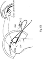
- FIG. 15A illustrates a padded transosseous suture (PTS) 1540, shown in situ after PTS 1540 has been implanted in bone 1530.
- PTS 1540 may comprise a suture 1541, seen in the side view of Fig. 15A , and a padding 1546.
- Suture 1541 may be divided, generally into three segments, a tunnel segment 1542, a padded segment 1544 and an extending section 1552, where padding 1546 around a portion of padded segment 1544.
- Tunnel segment 1542 may connect to a rear section 1548 of padding 1546 and may extend, when in situ, from the back of first tunnel 1526 up through tunnel 1528 and through tendon 1529. It may continue on top of tendon 1529 to padding segment 1544.
- padding 1546 When in situ, padding 1546 may be folded inside of first tunnel 1526. Padding segment 1544 may extend into first tunnel 1526 where it may pass through padding 1546 and thus, may also be folded. It may extend back out of tunnel 1526, becoming extending segment, labeled 1552, which may also be used to tie off suture 1541.
- an unpressed fold in a fabric generally is an area where the fabric is thick.
- the area of the fold, labeled 1554 may be an area of greater friction and may serve to hold PTS 1540 in place in first tunnel 1526.
- padding 1546 may be sized such that, at fold 1554, padding 1546 may push against first tunnel 1526.
- second tunnel 1528 may be at an angle, such as between 40 and 170 degrees, with first tunnel 1526, padding 1546 may not move into second tunnel 1528.
- padding 1546 may both hold PTS 1540 in situ and may pad padded segment 1544 to keep it from rubbing against the inner surface of first tunnel 1526. Moreover, due to the connection of tunnel segment 1542 at the back of fold 1554, tunnel segment 1542 may be held largely in the middle of second tunnel 1528 and thus, may also not rub against the inner surface of second tunnel 1528.
- PTS 1540 may be self-locking inside tunnel 1528 due to the friction against fold 1554. Accordingly, PTS 1540 will generally not move from its final position.
- PTS 1540 may be placed into tunnels 1526 and 1528 by pulling tunnel segment 1542 (which may already be in the tunnels, as described in more detail hereinbelow) from the entrance of first tunnel 1526 towards second tunnel 1528. Since tunnel segment 1542 may be connected to rear segment 1548, it may force padding 1546 to fold in order to enter first tunnel 1528. Pulling tunnel segment 1542 further may pull padding 1546 into first tunnel 1528.
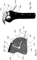
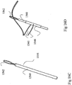
- FIGs. 16A and 16B illustrates PTS 1540 before it is implanted in the bone and shows suture 1541 passing through padding 1546, thereby to connect suture 1541 to padding 1546.
- suture 1541 may have two strings, labeled 1541A and 1541B, enabling the two ends of suture 1541 to be easily tied.
- strings 1541A and 1541B may be separately connected to padding 1546 or they may be formed from a doubling over of suture 1541.
- Padding 1546 may be formed of any suitable material which may be bio-compatible and may be flexible enough to fold and through which suture 1541 may be threaded and pulled.
- padding 1546 may be a generally cylindrical shape made of a braided material and/or may be made with a braid similar to that of a shoestring.
- padding 1546 may be formed from a bio-compatible silicone or plastic.
- padding 1546 may be any suitable bio-compatible material which may be flexible and foldable, and through which suture 1541 may be threaded, as described hereinbelow.
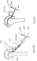
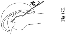
- FIGs. 17A - 17K illustrate the process of implanting PTS 1540 into bone 1530.
- Figs. 17A - 17K generally show the bone in a side view and thus, for clarity, do not always show both strings of suture 1541.
- Fig. 17A shows bone 1530 after creating transosseous tunnels 1526 and 1528.
- the transosseous process leaves a wire shuttle 1570 threaded through tunnels 1526 and 1528, and through a cut 1571 in the skin. Note that tendon 1529 is not yet connected to bone 1530.
- Shuttle 1570 has a loop 1572 into which a surgeon may thread strings 1541A and 1541B of suture 1541, as shown in Fig. 17B .
- handle 1560 is still held within padding 1546.
- Fig. 17B also shows a second set of exit holes 1573 for the second PTS 1540 so that a surgeon may tie a criss-cross stitch. The remaining discussion will show the process on only one PTS 1540.
- the surgeon may pull wire shuttle 1570 through bone 1530, thereby replacing wire shuttle 1570 with suture 1541. Using appropriate surgical tools, such as suture passers, the surgeon may then pass suture 1541 through tendon 1529 and back out of the body through cut 1571. The result is shown in Fig. 17C .
- a tendon to be repaired will have non-straight edge.
- the surgeon may pass suture 1541 through a point 1545 some distance behind the tear. During the process described hereinbelow, this point may be pulled forward towards the opening of the transosseous tunnel.
- the surgeon may now thread suture 1541 through wire loop 1562 of handle 1560, as shown in Fig. 17D .
- Pulling handle 1560 ( Fig. 17E ) may pull suture 1541 through padding 1546, thereby creating a loop from suture 1541, which is now looped through padding 1546.
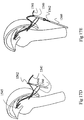
- portion 1580 will fold padding 1546 and bring it fully into first tunnel 1526 ( Fig. 17I ).
- the surgeon may pull padding 1546 through tunnel 1526 until padding 1546 stops. This may be at any point within tunnel 1526 but it will not extend beyond the intersection of the first tunnel and the second tunnel 1528 where the angle would require applying additional force to be applied in order to overcome the friction and resistance of moving around the angle of the turn.
- suture 1541 may be tightened. There are two steps to this:
- suture 1541 may be tied together (recall that there are two of them) in a knot over cut 1571, in a criss-cross knot, a button closure or with any other suitable closure. After this, suture 1541 may be cut.
- suture 1541 may be fixed due to frictions in tunnel 1526, from padding against the walls of tunnel 1526 but also from the fact that padding 1546 is folded. Moreover, pulling on the portions of suture 1541 external to the skin may pull on fold 1554 of padding 1546, which, in turn, may pull on padding segments 1544, which are connected to the external pulled portions.
- padding 1546 may be pulled out of the joint, by pulling backwards on segment 1580 or on extending segment 1552. Similarly, padding 1546 may be pulled out after cutting suture 1541.
- padding 1546 may be forced to bend, which creates a strong friction connection to first tunnel 1526 in the bone.
- PTS 1540 may be utilized with any suitable transosseous tunnel(s). For example and as shown in Fig. 18 , to which reference is now made, PTS 1540 may be threaded through a circular tunnel 1590 rather than through two tunnels 1526 and 1528.
Landscapes
- Health & Medical Sciences (AREA)
- Life Sciences & Earth Sciences (AREA)
- Surgery (AREA)
- Veterinary Medicine (AREA)
- General Health & Medical Sciences (AREA)
- Animal Behavior & Ethology (AREA)
- Public Health (AREA)
- Engineering & Computer Science (AREA)
- Biomedical Technology (AREA)
- Heart & Thoracic Surgery (AREA)
- Rheumatology (AREA)
- Nuclear Medicine, Radiotherapy & Molecular Imaging (AREA)
- Medical Informatics (AREA)
- Molecular Biology (AREA)
- Oral & Maxillofacial Surgery (AREA)
- Vascular Medicine (AREA)
- Transplantation (AREA)
- Cardiology (AREA)
- Rehabilitation Therapy (AREA)
- Orthopedic Medicine & Surgery (AREA)
- Prostheses (AREA)
- Surgical Instruments (AREA)
Description
- The present invention relates to transosseous sutures.
- Various types of transosseous sutures are known in the art.
- It is appreciated that the term "suture" as used throughout the description of the present invention refers to any suitable suture and also refers to a transfer wire or pull wire which is used to pull a suture through the bone. Typically, a transfer wire is used with the system of the present invention and is formed of Nitinol. Typically, a transfer wire used with the system of the present invention is folded over to form a loop at one end.
- The present invention seeks to provide improved transosseous sutures and is defined by the features of appended independent claim 1. Preferred embodiments are defined by the dependent claims.
- The present invention will be understood and appreciated more fully from the following detailed description, taken in conjunction with the drawings in which
figures 5A-6B and8A-8B show embodiments of the invention as claimed, and in which: -
Figs. 1A &1B are simplified respective pictorial and sectional illustrations of a transosseous suture assembly in a first operative orientation; -
Figs. 2A &2B are simplified respective pictorial and sectional illustrations of the transosseous suture assembly ofFigs. 1A &1B in a second operative orientation; -
Figs. 3A &3B are simplified respective pictorial and sectional illustrations of a transosseous suture assembly in a first operative orientation; -
Figs. 4A &4B are simplified respective pictorial and sectional illustrations of the transosseous suture assembly ofFigs. 3A &3B in a second operative orientation; -
Figs. 5A &5B are simplified respective pictorial and sectional illustrations of a transosseous suture assembly constructed and operative in accordance with the present invention in a first operative orientation; -
Figs. 6A &6B are simplified respective pictorial and sectional illustrations of the transosseous suture assembly ofFigs. 5A &5B in a second operative orientation; -
Figs. 7A &7B are simplified respective pictorial and sectional illustrations of a transosseous suture assembly in a first operative orientation; -
Figs. 8A &8B are simplified respective pictorial and sectional illustrations of a transosseous suture assembly constructed and operative in accordance with the present invention in a first operative orientation; -
Figs. 9A &9B are simplified respective pictorial and sectional illustrations of a transosseous suture assembly in a first operative orientation; -
Figs. 10A &10B are simplified respective pictorial and sectional illustrations of a transosseous suture assembly in a first operative orientation; -
Figs. 11A &11B are simplified respective pictorial and sectional illustrations of the transosseous suture assembly ofFigs. 10A &10B in a second operative orientation; -
Figs. 12A ,12B ,12C ,12D and12E are together a simplified illustration of some preliminary stages of the insertion of a transosseous suture assembly of any of the embodiments illustrated inFigs. 1A - 11B ; -
Figs. 13A ,13B ,13C ,13D ,13E ,13F &13G are simplified illustrations of the penultimate stage of the insertion of the transosseous suture assembly of various embodiments illustrated inFigs. 1A - 2B ,Figs. 3A - 4B ,Figs. 5A - 6B ,Figs. 7A &7B ,Figs. 8A &8B ,Figs. 9A &9B , andFigs. 10A - 11B , respectively; -
Fig. 14 is a simplified illustration of a final stage of the insertion of the transosseous suture assembly of all of the various embodiments illustrated inFigs. 1A -11B ; -
Figs. 15A and 15B are schematic illustrations of a padded transosseous suture configuration, in cross-section and in solid, where the suture is passed through a protective fixation sleeve, in situ; -
Figs. 16A & 16B are schematic and cross-sectional illustrations, respectively, of a protective fixation sleeve and a suture passed through a cross section of the sleeve, prior to implantation; -
Fig. 16C is a schematic illustration of a threader for the suture ofFig. 16A ; -
Fig. 16D is a schematic illustration of the sleeve and suture ofFig. 16A with the threader ofFig. 16C passed through the sleeve, prior to implantation; -
Figs. 17A ,17B ,17C ,17D ,17E ,17F ,17G ,17H ,17I ,17J and17K are schematic illustrations of the process of implanting the padded transosseous suture ofFigs. 16A -16D ; and -
Fig. 18 is a schematic illustration of an alternative embodiment of the present disclosure. - In the following detailed description, numerous specific details are set forth in order to provide a thorough understanding of the invention. However, it will be understood by those skilled in the art that the present invention may be practiced without these specific details. In other instances, well-known methods, procedures, and components have not been described in detail so as not to obscure the present invention.
- Reference is now made to
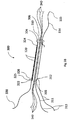
Figs. 1A &1B , which are simplified respective pictorial and sectional illustrations of a transosseous suture assembly in a first operative orientation. As seen inFigs 1A &1B , the transosseous suture assembly preferably includes a flexible anddeformable sleeve 100, preferably formed of a polyester mesh such as polyester peek or nylon, or nitinol or cotton. Flexible anddeformable sleeve 100 includes a generally circularly cylindricalmain portion 102 having a first outer diameter of, typically slightly less than 3.2mm in the first operative orientation wheresleeve 100 is in a relaxed, extended state, and an outwardly extendingflange portion 104, having a second outer diameter greater than the first outer diameter ofmain portion 102. Abore 106 extends from afirst end 108 of the flexible anddeformable sleeve 100 to asecond end 110 of the flexible anddeformable sleeve 100 atflange portion 104. - A first
flexible thread 112 is attached to flexible anddeformable sleeve 100 adjacentfirst end 108 thereof and has afree end 113 extending beyondfirst end 108 and a secondflexible thread 114 is attached to flexible anddeformable sleeve 100 adjacentsecond end 110 thereof and has afree end 115 extending beyondsecond end 110. Asleeve shortening thread 120 is preferably threaded through anaperture 126 at oneend 122 of the flexible anddeformable sleeve 100 adjacentfirst end 108 thereof and extends along most of the length of the sleeve to and through anaperture 124 adjacent thesecond end 110 of the flexible anddeformable sleeve 100 and is looped back and fastened tofirst end 125 of thesleeve shortening thread 120 nearaperture 126 and has afree end 130 extending beyondend 108. - A plurality of lengths of suture, typically three in number, here collectively designated by
reference numeral 140, extend through flexible anddeformable sleeve 100 and beyond both ends 108 and 110 thereof. - Reference is now made to
Figs. 2A &2B , which are simplified respective pictorial and sectional illustrations of the transosseous suture assembly ofFigs. 1A &1B in a second operative orientation, which results from pulling on thefree end 130 ofsleeve shortening thread 120 while holding flexible anddeformable sleeve 100. As seen inFigs. 2A and2B and comparing them withFigs. 1A &1B , the overall length of the loop ofsleeve shortening thread 120, which extends throughapertures deformable sleeve 100, typically as shown. This effectively widens the diameter of the flexible anddeformable sleeve 100. - Reference is now made to
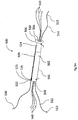
Figs. 3A &3B , which are simplified respective pictorial and sectional illustrations of a transosseous suture assembly in a first operative orientation. As seen inFigs 3A &3B , the transosseous suture assembly preferably includes a flexible anddeformable sleeve 300, preferably formed of a polyester mesh such as polyester peek or nylon, or nitinol or cotton. Flexible anddeformable sleeve 300 includes a generally circularly cylindricalmain portion 302 having a first outer diameter of, typically slightly less than 3.2mm in a relaxed, extended state, and an outwardly extendingflange portion 304, having a second outer diameter greater than the first outer diameter ofmain portion 302. Abore 306 extends from afirst end 308 of the flexible anddeformable sleeve 300 to asecond end 310 of the sleeve atflange portion 304. - A first
flexible thread 311 is attached to flexible anddeformable sleeve 300 by being looped through anaperture 312 formed therein adjacentfirst end 308 thereof and has twofree ends 313 extending beyondfirst end 308 and a secondflexible thread 314 is attached to flexible anddeformable sleeve 300 adjacentsecond end 310 thereof and has afree end 315 extending beyondsecond end 310. Asleeve shortening thread 320 is preferably threaded through anaperture 326 at oneend 322 of the flexible anddeformable sleeve 300 adjacentfirst end 308 thereof and extends along most of the length of the sleeve to and through anaperture 324 adjacent thesecond end 310 of the flexible anddeformable sleeve 300 and is looped back and fastened tofirst end 325 of thesleeve shortening thread 320 nearaperture 326 and has afree end 330 extending beyondend 308. - A plurality of lengths of suture, typically three in number, here collectively designated by
reference numeral 340, extend through flexible anddeformable sleeve 300 and beyond both ends 308 and 310 thereof. - Reference is now made to
Figs. 4A &4B , which are simplified respective pictorial and sectional illustrations of the transosseous suture assembly ofFigs. 3A &3B in a second operative orientation, which results from pulling on thefree end 330 ofsleeve shortening thread 320 while holding flexible anddeformable sleeve 300. As seen inFigs. 4A and4B and comparing them withFigs. 3A &3B , the overall length of the loop ofsleeve shortening thread 320, which extends throughapertures deformable sleeve 300, typically as shown. This effectively widens the flexible anddeformable sleeve 300 and increases the diameter thereof to a second outer diameter greater than the first outer diameter of the first operative orientation shown inFigs 3A &3B . - Reference is now made to
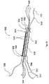
Figs. 5A &5B , which are simplified respective pictorial and sectional illustrations of a transosseous suture assembly constructed and operative in accordance with the present invention in a first operative orientation. As seen inFigs 5A &5B , the transosseous suture assembly preferably includes a flexible anddeformable sleeve 500, preferably formed of a polyester mesh such as polyester peek or nylon, or nitinol or cotton. Flexible anddeformable sleeve 500 includes a generally circularly cylindricalmain portion 502 having a first outer diameter of, typically slightly less than 3.2mm in a relaxed, extended state, and an outwardly extendingflange portion 504, having a second outer diameter greater than the first outer diameter ofmain portion 502. Abore 506 extends from afirst end 508 of the flexible anddeformable sleeve 500 to asecond end 510 of the sleeve atflange portion 504. - A first
flexible thread 512 is attached to flexible anddeformable sleeve 500 adjacentfirst end 508 thereof and has afree end 513 extending beyondfirst end 508 and a secondflexible thread 514 is attached to flexible anddeformable sleeve 500 adjacentsecond end 510 thereof and has afree end 515 extending beyondsecond end 510. Asleeve shortening thread 520 is preferably threaded through anaperture 526 at oneend 522 of the flexible anddeformable sleeve 500 adjacentfirst end 508 thereof and extends along most of the length of the sleeve to and through anaperture 524 adjacent thesecond end 510 of the flexible anddeformable sleeve 500 and is looped back and fastened tofirst end 525 of thesleeve shortening thread 520 nearaperture 526 and has afree end 530 extending beyondend 508. - A plurality of lengths of suture, typically three in number, here collectively designated by
reference numeral 540, extend through flexible anddeformable sleeve 500 and beyond both ends 508 and 510 thereof. Attached nearfirst end 508 of flexible anddeformable sleeve 500 is an outersecond sleeve 550 whose diameter is approximately equal to that of the exterior of the generally circularly cylindricalmain portion 502 so that flexible anddeformable sleeve 500 may be inserted into outersecond sleeve 550 and become engaged within. Outersecond sleeve 550 extends typically two-thirds to three-quarters the length of flexible anddeformable sleeve 500 to end 560, is preferably formed of a polyester mesh such as polyester peek or nylon, or nitinol or cotton and is flexible and deformable. Firstflexible thread 512, in addition to being attached to flexible anddeformable sleeve 500, is also attached to outersecond sleeve 550 adjacentfirst end 508 of flexible anddeformable sleeve 500. - Reference is now made to
Figs. 6A &6B , which are simplified respective pictorial and sectional illustrations of the transosseous suture assembly ofFigs. 5A &5B in a second operative orientation, which results from pulling on thefree end 530 ofsleeve shortening thread 520 while holding flexible anddeformable sleeve 500. As seen inFigs. 6A and6B and comparing them withFigs. 5A &5B , the overall length of the loop ofsleeve shortening thread 520, which extends throughapertures deformable sleeve 500, typically as shown, with both the flexible anddeformable sleeve 500 and the outersecond sleeve 550 contracting between theend 560 of the outersecond sleeve 550 and thefirst end 508 of the flexible and deformable sleeve. This effectively increases the diameter of the combined flexible anddeformable sleeve 500 and the outersecond sleeve 550 between theend 560 of the outersecond sleeve 550 and thefirst end 508 of the flexible anddeformable sleeve 500. Inclusion of the outersecond sleeve 550 significantly increases the total amount of material in the contracted region between theend 560 of the outersecond sleeve 550 and thefirst end 508 of the flexible and deformable sleeve, as compared to only the flexible anddeformable sleeve 500, and thus results in the dual sleeve having a greater total diameter. - Reference is now made to
Figs. 7A &7B , which are simplified respective pictorial and sectional illustrations of a transosseous suture assembly. As seen inFigs 7A &7B , the transosseous suture assembly preferably includes aflexible sleeve 700, preferably formed of a polyester mesh such as polyester peek or nylon, or nitinol or cotton.Flexible sleeve 700 including a generally circularly cylindricalmain portion 702 having a first outer diameter of, typically slightly less than 3.2mm, and an outwardly extendingflange portion 704, having a second outer diameter greater than the first outer diameter ofmain portion 702. Abore 706 extends from afirst end 708 of theflexible sleeve 700 to asecond end 710 of the sleeve. - A
flexible thread 712 is loosely stitched along the length offlexible sleeve 700 from a location adjacentfirst end 708 thereof and has afree end 713 extending beyondfirst end 708 to a location adjacentsecond end 710 thereof and has afree end 715 extending beyondsecond end 710.Flexible thread 712, in this embodiment, is an alternative to having first and second threads attached to flexible sleeve 700 (seeFig. 13D below);flexible sleeve 700 may be manufactured withflexible thread 712 imbedded, thus obviating the need for manual affixing or looping of threads intoflexible sleeve 700. A plurality of lengths of suture, typically three in number, here collectively designated byreference numeral 740, extend throughflexible sleeve 700 and beyond both ends 708 and 710 thereof. - Reference is now made to
Figs. 8A &8B , which are simplified respective pictorial and sectional illustrations of a transosseous suture assembly constructed and operative in accordance with the present invention. As seen inFigs 8A &8B , the transosseous suture assembly preferably includes aflexible sleeve 800, preferably formed of a polyester mesh such as polyester peek or nylon, or nitinol or cotton.Flexible sleeve 800 including a generally circularly cylindricalmain portion 802 having a first outer diameter of, typically slightly less than 3.2mm, and an outwardly extendingflange portion 804, having a second outer diameter greater than the first outer diameter ofmain portion 802. Abore 806 extends from afirst end 808 of theflexible sleeve 800 to asecond end 810 of the sleeve atflange portion 804. - A first
flexible thread 812 is attached toflexible sleeve 800 adjacentfirst end 808 thereof and has afree end 813 extending beyondfirst end 808 and a secondflexible thread 814 is attached toflexible sleeve 800 adjacentsecond end 810 thereof and has afree end 815 extending beyondsecond end 810. Optionally as shown, a tighteningthread 820 is threaded through anaperture 826 at oneend 822 of theflexible sleeve 800 adjacentfirst end 808 thereof and extends along most of the length of the sleeve to and through anaperture 824 adjacent thesecond end 810 of theflexible sleeve 800 and is looped back and fastened tofirst end 825 of the tighteningthread 820 nearaperture 826 and has afree end 830 extending beyondend 808. - A plurality of lengths of suture, typically three in number, here collectively designated by
reference numeral 840, extend throughflexible sleeve 800 and beyond both ends 808 and 810 thereof. Attached nearfirst end 808 offlexible sleeve 800 is a flared outersecond sleeve 850, having a cylindrical portion and a conical portion whose cylindrical portion has a diameter approximately matching that of the exterior of the generally circularly cylindricalmain portion 802 near thefirst end 808 and whose diameter increases toward thesecond end 810 of theflexible sleeve 800. Flared outersecond sleeve 850 has a horn-like shape, open atend 860, and is flexible. - Reference is now made to
Figs. 9A &9B , which are simplified respective pictorial and sectional illustrations of a transosseous suture assembly. As seen inFigs 9A &9B , the transosseous suture assembly preferably includes aflexible sleeve 900, preferably formed of a polyester mesh such as polyester peek or nylon, or nitinol or cotton. Flexible anddeformable sleeve 900 includes a generally circularly cylindricalmain portion 902 having a first outer diameter of, typically slightly less than 3.2mm, and an outwardly extendingflange portion 904, having a second outer diameter greater than the first outer diameter ofmain portion 902. Abore 906 extends from afirst end 908 of theflexible sleeve 900 to asecond end 910 of the sleeve. - A first
flexible thread 912 is attached toflexible sleeve 900 adjacentfirst end 908 thereof and has afree end 913 extending beyondfirst end 908 and a secondflexible thread 914 is attached toflexible sleeve 900 adjacentsecond end 910 thereof and has afree end 915 extending beyondsecond end 910. A plurality of lengths of suture, typically three in number, here collectively designated byreference numeral 940, extend throughflexible sleeve 900 and beyond both ends 908 and 910 thereof. - Reference is now made to
Figs. 10A &10B , which are simplified respective pictorial and sectional illustrations of a transosseous suture assembly in a first operative orientation. As seen inFigs 10A &10B , the transosseous suture assembly preferably includes a flexible anddeformable braided sleeve 1000, preferably formed of a polyester mesh such as polyester peek or nylon, or nitinol or cotton. Flexible anddeformable braided sleeve 1000 including a generally circularly cylindricalmain portion 1002 having a first outer diameter of, typically slightly less than 3.2mm in a relaxed, extended state, and an outwardly extendingflange portion 1004, having a second outer diameter greater than the first outer diameter ofmain portion 1002. Abore 1006 extends from a first end 1008 of the flexible anddeformable braided sleeve 1000 to asecond end 1010 of the sleeve atflange portion 1004. - A first
flexible thread 1011 is attached to flexible anddeformable braided sleeve 1000 by being looped through anaperture 1012 formed therein adjacent first end 1008 thereof and has twofree ends 1013 extending beyond first end 1008 and a secondflexible thread 1014 is attached to flexible anddeformable braided sleeve 1000 adjacentsecond end 1010 thereof and has afree end 1015 extending beyondsecond end 1010. In an alternative embodiment, firstflexible thread 1011 is affixed to flexible anddeformable braided sleeve 1000 ataperture 1012 adjacent first end 1008 and has afree end 1013 extending beyond first end 1008. A tighteningthread 1020 is preferably threaded through anaperture 1026 at one end 1022 of the flexible anddeformable braided sleeve 1000 adjacent first end 1008 thereof and extends along most of the length of the sleeve to and through anaperture 1024 adjacent thesecond end 1000 of the flexible anddeformable braided sleeve 1000 and is looped back and fastened tofirst end 1025 of thetightening thread 1020 nearaperture 1026 and has afree end 1030 extending beyond end 1008. - A plurality of lengths of suture, typically three in number, here collectively designated by
reference numeral 1040, extend through flexible anddeformable braided sleeve 1000 and beyond both ends 1008 and 1010 thereof.Adjacent flange 1004 atsecond end 1010 of the flexible anddeformable braided sleeve 1000, the flexible anddeformable braided sleeve 1000 has been pre-stressed or pre-formed and, as shown, a torus shaped portion 1050 is made in the flexible anddeformable braided sleeve 1000 with an outer diameter typically about 6mm. As shown inFigs. 10A &10B , the pre-stressed flexible anddeformable braided sleeve 1000 is in a relaxed state. In an alternative embodiment, flexible anddeformable braided sleeve 1000 is not pre-stressed and is thus generally circularly cylindrical with no torus shaped portion 1050 pre-formed. - Reference is now made to
Figs. 11A &11B , which are simplified respective pictorial and sectional illustrations of the transosseous suture assembly ofFigs. 10A &10B in a second operative orientation, which results from pulling on the free ends 1013 of firstflexible thread 1011 while holding secondflexible thread 1014. As seen inFigs. 11A and11B and comparing them withFigs. 10A &10B , the overall length of the flexible anddeformable braided sleeve 1000 is increased, thus longitudinally stretching the flexible anddeformable braided sleeve 1000, specifically flattening the pre-formed torus shape 1050, typically as shown. This effectively narrows the diameter of the flexible anddeformable braided sleeve 1000 to a near uniform diameter, typically slightly less than 3.2mm. - It is understood that, in an alternative embodiment with a non pre-stressed flexible and
deformable braided sleeve 1000, the flexible anddeformable braided sleeve 1000 will appear as is shown inFig. 11A &11B , when in a relaxed state. - Reference is now made to
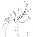
Figs. 12A ,12B ,12C ,12D &12E , which are together a simplified illustration of some preliminary stages of the insertion of a transosseous suture assembly of any of the embodiments illustrated inFigs. 1A - 11B ; - Referring specifically to
Fig. 12A , which is a simplified illustration of a first stage of the insertion of a transosseous suture assembly into a bone, it is seen that a first loopedtransfer wire 1200 has been inserted into aside bore 1202 made in a bone and has been pulled through the bone until it exits atop bore 1204 made in the bone.Loop 1206 of first loopedtransfer wire 1200 extends outsidetop bore 1204 and a pair ofloose ends 1208 of first loopedtransfer wire 1200 extend outside side bore 1202. It is noted (shown below inFigs. 13A - 13G ) thattop bore 1204 is generally narrower than side bore 1202 and intersectsside bore 1202 within the osseous portion of the bone at nearly a right angle. - Referring now specifically to
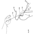
Fig. 12B , which is a simplified illustration of a second stage of the insertion of a transosseous suture assembly into a bone, it is seen that a second loopedtransfer wire 1210 has been inserted intoloop 1206 of first loopedtransfer wire 1200 extending outsidetop bore 1204 in bone.Loop 1216 of second loopedtransfer wire 1210 extends throughloop 1206 of first loopedtransfer wire 1200 while a pair ofloose ends 1218 of second loopedtransfer wire 1210 extend outside other side ofloop 1206 of first loopedtransfer wire 1200. Following this second stage of the insertion of a transosseous suture assembly into a bone, the first loopedtransfer wire 1200 is pulled through the bone from thetop bore 1204 through the side bore 1202, pulling the second loopedtransfer wire 1210 through the bone with it. - Reference is now made to
Fig. 12C , which is a simplified illustration of a third stage of the insertion of a transosseous suture assembly into a bone. In this stage it is seen that the second loopedtransfer wire 1210 has been pulled through the top bore 1204 (as described above in reference toFig. 12B ) and out the side bore 1202;loop 1216 now extends outside side bore 1202 with the pair ofloose ends 1218 extending out oftop bore 1204 resulting in the second loopedtransfer wire 1210 being in the reverse position of the first loopedtransfer wire 1200, as seen inFig. 12A . - Referring now specifically to
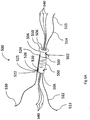
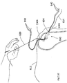
Fig. 12D , which is a simplified illustration of a fourth stage of the insertion of a transosseous suture assembly into a bone, it is seen that atransosseous suture 1240 has been inserted through theloop 1216 of the second loopedtransfer wire 1210, which extends outside side bore 1202 in bone.Transosseous suture 1240 comprises a generallycylindrical portion 1242 with a plurality of sutures 1244, typically three, threaded through abore 1246 formed in generallycylindrical portion 1242 and extending fromfirst end 1248 tosecond end 1250 of generallycylindrical portion 1242 oftransosseous suture 1240, and an outwardly extendingflange portion 1251. It is understood that, when referring here to thetransosseous suture 1240, reference is being made to any one of the above defined flexible sleeve embodiments. Sutures 1244 havefree ends 1252 atfirst end 1248, shown extending throughloop 1216 of the second loopedtransfer wire 1210, andfree ends 1254 extending fromsecond end 1250 of the generallycylindrical portion 1242 of thetransosseous suture 1240. Following this fourth stage of the insertion of a transosseous suture assembly into a bone, the second loopedtransfer wire 1210 is pulled through the bone from the side bore 1202 through thetop bore 1204, pulling thetransosseous suture 1240 into the side bore 1202 in the bone.Sutures top bore 1204 and side bore 1202, respectively, are affixed and/or looped through apertures intransosseous suture 1240. - Reference is now made to
Figs. 12E , which is a simplified pictorial illustration of a fifth stage in the insertion of a transosseous suture assembly into a bone. It is seen thattransosseous suture 1240 has become engaged within side bore 1202 in the bone and sutures 1244 have been pulled throughtop bore 1204 in bone. In this stage, the free ends 1252 of thetransosseous suture 1240 extend outside thetop bore 1204, while the free ends 1254 at the opposite end of thetransosseous suture 1240 extend outside the side bore 1202 in the bone.Transosseous suture 1240 has become engaged in side bore 1204 and cannot progress intotop bore 1204 becausetop bore 1204 is narrow and because nearly right angle formed at intersection oftop bore 1204 and side bore 1202 both inhibit passage, as described above in reference toFig. 12A , and because of outwardly extendingflange portion 1251 which inhibits complete passage of thetransosseous suture 1240 into the side bore 1204, being generally wider than the diameter of theside bore 1204. It is understood and described below that, some embodiments may become more tightly engaged in bone by pulling on locking suture 1280, when locking suture 1280 is present. - Reference is now made to
Figs. 13A ,13B ,13C &13D ,13E ,13F & 13G , which are simplified sectional illustrations of the penultimate stage of the insertion of the transosseous suture assembly, as described above in relation toFig. 12E , of the various embodiments illustrated inFigs. 1A - 2B ,Figs. 3A - 4B ,Figs. 5A - 6B ,Figs. 7A & B ,Figs. 8A & B ,Figs. 9A & B andFigs. 10A - 11B , respectively. Each ofFigs. 13A ,13B ,13C ,13D ,13E .13F &13G demonstrate the effect on the sleeve of pulling a suture attached to the sleeve from the top bore, engaging the sleeve within the side bore of the bone. It is understood that each ofFigs. 13A - 13G are respective sectional illustrations ofFig. 12E , one illustration per embodiment, as described and shown in connection withFigs. 1A - 11B . Reference is now made toFig. 13A , which is a simplified sectional illustration of the penultimate stage of the insertion of the transosseous suture assembly of the embodiment illustrated inFigs. 1A - 2B . As shown, the flexible anddeformable sleeve 100, described in relation toFigs. 1A - 2B , becomes tightly engaged in the side bore 1302 of the bone after first being pulled into the side bore 1302 when firstflexible thread 112 is pulled from outsidetop bore 1304, then havingsleeve shortening thread 120 pulled from outsidetop bore 1304. Pullingsleeve shortening thread 120 causes distension of the middle section of the flexible anddeformable sleeve 100 widening it and further engaging it in the bone. A plurality of lengths ofsuture 140 are seen to extend from both the side bore 1302 and thetop bore 1304. - Reference is now made to
Fig. 13B , which is a simplified sectional illustration of the penultimate stage of the insertion of the transosseous suture assembly of the embodiment illustrated inFigs. 3A - 4B . As shown, the flexible anddeformable sleeve 300, described in relation toFigs. 3A - 4B , becomes tightly engaged in the side bore 1302 of the bone after first being pulled into the side bore 1302 when firstflexible thread 311 is pulled from outsidetop bore 1304, then having tighteningsuture 320 pulled from outsidetop bore 1304. Pulling tighteningsuture 320 causes distension of the middle section of the flexible anddeformable sleeve 300 widening it and further engaging it in the bone. Optionally, firstflexible thread 311 may be pulled from top bore of bone by one of free ends 313 so that it is removed from flexible anddeformable sleeve 300, once flexible anddeformable sleeve 300 is fully engaged in side bore of bone. A plurality of lengths ofsuture 340 are seen to extend from both the side bore 1302 and thetop bore 1304. - Reference is now made to
Fig. 13C , which is a simplified sectional illustration of the penultimate stage of the insertion of the transosseous suture assembly of the embodiment illustrated inFigs. 5A - 6B . As shown, the flexible anddeformable sleeve 500, described in relation toFigs. 5A - 6B and having an outersecond sleeve 550, becomes tightly engaged in the side bore 1302 of the bone after first being pulled into the side bore 1302 whensuture 512 is pulled from outsidetop bore 1304, then havingsleeve shortening thread 520 pulled from outsidetop bore 1304. Pullingsleeve shortening thread 520 causes distension of the middle section of both the flexible anddeformable sleeve 500 and the outersecond sleeve 550, widening them and further engaging the flexible anddeformable sleeve 500 in the bone. A plurality of lengths ofsuture 540 are seen to extend from both the side bore 1302 and thetop bore 1304. - Reference is now made to
Fig. 13D , which is a simplified sectional illustration of the penultimate stage of the insertion of the transosseous suture assembly of the embodiment illustrated inFigs. 7A &7B . As shown, theflexible sleeve 700, described in relation toFigs. 7A &7B , becomes engaged in the side bore 1302 of the bone after being pulled into the side bore 1302 whenflexible thread 712 is pulled from outsidetop bore 1304. In other embodiments, a suture either fixed to, or looped through an aperture in sleeve is used to pull the sleeve into the bone. A plurality of lengths ofsuture 740 are seen to extend from both the side bore 1302 and thetop bore 1304. - Reference is now made to
Figs. 13E , which is a simplified sectional illustration of the penultimate stage of the insertion of the transosseous suture assembly of the embodiment illustrated inFigs. 8A &8B . As shown, theflexible sleeve 800, described in relation toFigs. 8A &8B , becomes tightly engaged in the side bore 1302 of the bone after being pulled into the side bore 1302 when firstflexible thread 812 is pulled from outsidetop bore 1304. Whenflexible sleeve 800 is pulled into bone, the flared outersecond sleeve 850 flexes and its outer diameter is decreased as it passes into theside bore 1302. Once inside the osseous portion of the bone, the flared outer second sleeve recovers to near the original shape and, thus widened, causes tighter engagement in the bone. Whenoptional tightening thread 820 is attached to flexible anddeformable sleeve 800, it may be used to further tighten the engagement of the flexible sleeve in the bone by tying it together outside bone, similar to what is shown inFig. 14 below. A plurality of lengths ofsuture 840 are seen to extend from both the side bore 1302 and thetop bore 1304. - Reference is now made to
Figs. 13F , which is a simplified sectional illustration of the penultimate stage of the insertion of the transosseous suture assembly of the embodiment illustrated inFigs. 9A &9B . As shown, theflexible sleeve 900, described in relation toFigs. 9A &9B , becomes engaged in the side bore 1302 of the bone after being pulled into the side bore 1302 when firstflexible thread 912 is pulled from outsidetop bore 1304. A plurality of lengths ofsuture 940 are seen to extend from both the side bore 1302 and thetop bore 1304. - Reference is now made to
Fig. 13G , which is a simplified sectional illustration of the penultimate stage of the insertion of the transosseous suture assembly of the embodiment illustrated inFigs. 10A - 11B . As shown, the flexible anddeformable braided sleeve 1000, described in relation toFigs. 10A - 11B , becomes tightly engaged in the side bore 1302 of the bone after first being stretched then pulled into the side bore 1302 when firstflexible thread 1011 is pulled from outsidetop bore 1304. The stretching causes the torus shaped portion 1050 of flexible anddeformable braided sleeve 1000 to compress and the flexible anddeformable braided sleeve 1000 to approximate a generally circular cylindrical shape, allowing passage of the flexible anddeformable braided sleeve 1000 into the side bore 1302 of the bone. Upon entry into the osseous portion of the bone, and once tension caused by pulling on the firstflexible thread 1011 is relaxed, the flexible anddeformable braided sleeve 1000 relaxes and the pre-formed torus shaped portion 1050 reasserts itself, tightly engaging the flexible anddeformable braided sleeve 1000 in the bone, as shown. Optionally, tighteningthread 1020, when present, may tied together outside bone thus further tightening engagement of the transosseous suture in the bone. Optionally, firstflexible thread 1011 may be pulled from top bore of bone by one offree ends 1013 so that it is removed from flexible anddeformable sleeve 1000, once flexible anddeformable braided sleeve 1000 is fully engaged in side bore of bone. A plurality of lengths ofsuture 1040 are seen to extend from both the side bore 1302 and thetop bore 1304. - Alternatively, when the flexible and
deformable braided sleeve 1000 has not been pre-stressed or pre-formed and flexible anddeformable braided sleeve 1000 is generally circularly cylindrical in a relaxed state, the flexible anddeformable braided sleeve 1000 becomes tightly engaged in the side bore 1302 of the bone after first being pulled into the side bore 1302 when firstflexible thread 1011 is pulled from outsidetop bore 1304, then havingtightening thread 1020 pulled from outsidetop bore 1304. Pulling tighteningthread 1020 causes distension of the middle section of the flexible anddeformable braided sleeve 1000 widening it and further engaging it in the bone. Optionally, firstflexible thread 1011 may be pulled from top bore of bone by one offree ends 1013 so that it is removed from flexible anddeformable sleeve 1000, once flexible anddeformable sleeve 1000 is fully engaged in side bore of bone. - Reference is now made to
Fig. 14 , which is a simplified illustration of a final stage of the insertion of the transosseous suture assembly of each of the various embodiments illustrated inFigs. 1A - 11B . As shown, twoloose ends sutures top bore 1404 and one extending through the side bore 1402 respectively, are tied and knotted together tightly outside the bone, forming aknot 1480. This further engages the transosseous suture assembly within the bone. This final step is typically done for all embodiments of the current invention described above inFigs. 1A -11B . - Applicants have realized that although the transosseous approach efficiently fixates a suture in the bone, padding the inner walls of the tunnel would be advantageous in protecting the bone.
- Applicants have realized that passing a transosseous suture through a protective sleeve may protect the bone and may also assist in fixating the suture within the transosseous tunnel, preventing its movement and subsequent displacement from within the tunnel during deployment and thereafter.
- Reference is now made to
Fig. 15A , which illustrates a padded transosseous suture (PTS) 1540, shown in situ afterPTS 1540 has been implanted inbone 1530.PTS 1540 may comprise asuture 1541, seen in the side view ofFig. 15A , and apadding 1546.Suture 1541 may be divided, generally into three segments, atunnel segment 1542, apadded segment 1544 and an extendingsection 1552, wherepadding 1546 around a portion of paddedsegment 1544.Tunnel segment 1542 may connect to arear section 1548 ofpadding 1546 and may extend, when in situ, from the back offirst tunnel 1526 up throughtunnel 1528 and throughtendon 1529. It may continue on top oftendon 1529 topadding segment 1544. - When in situ,
padding 1546 may be folded inside offirst tunnel 1526.Padding segment 1544 may extend intofirst tunnel 1526 where it may pass throughpadding 1546 and thus, may also be folded. It may extend back out oftunnel 1526, becoming extending segment, labeled 1552, which may also be used to tie offsuture 1541. - Reference is now briefly made to
Fig. 15B which is an isometric solid drawing ofPTS 1540 after implantation.Suture 1541 can be seen going throughtendon 1529 to bring it in contact with thebone 1530, with extendingsegment 1552 extending fromfirst tunnel 1526. As shown hereinbelow inFig. 16A ,suture 1541 may be threaded through or otherwise connected topadding 1546, thereby to provide two of each suture segment. Thus, the two extendingsegments 1552 may be tied together in a knot at theopening 1527 offirst tunnel 1526 oncepadding 1546 is in place. This will preventsuture 1541 from moving in the tunnels and will keeptendon 1529 in place. - Applicants have realized that an unpressed fold in a fabric generally is an area where the fabric is thick. Thus, the area of the fold, labeled 1554, may be an area of greater friction and may serve to hold
PTS 1540 in place infirst tunnel 1526. Thus,padding 1546 may be sized such that, atfold 1554,padding 1546 may push againstfirst tunnel 1526. Moreover, sincesecond tunnel 1528 may be at an angle, such as between 40 and 170 degrees, withfirst tunnel 1526,padding 1546 may not move intosecond tunnel 1528. - It will be appreciated that
padding 1546 may both holdPTS 1540 in situ and may pad paddedsegment 1544 to keep it from rubbing against the inner surface offirst tunnel 1526. Moreover, due to the connection oftunnel segment 1542 at the back offold 1554,tunnel segment 1542 may be held largely in the middle ofsecond tunnel 1528 and thus, may also not rub against the inner surface ofsecond tunnel 1528. - It will also be appreciated that
PTS 1540 may be self-locking insidetunnel 1528 due to the friction againstfold 1554. Accordingly,PTS 1540 will generally not move from its final position. -
PTS 1540 may be placed intotunnels first tunnel 1526 towardssecond tunnel 1528. Sincetunnel segment 1542 may be connected torear segment 1548, it may forcepadding 1546 to fold in order to enterfirst tunnel 1528. Pullingtunnel segment 1542 further may pullpadding 1546 intofirst tunnel 1528. - Reference is now made to
Figs. 16A and 16B , which illustratesPTS 1540 before it is implanted in the bone and showssuture 1541 passing throughpadding 1546, thereby to connectsuture 1541 topadding 1546. As a result of passing through or otherwise being connected topadding 1546,suture 1541 may have two strings, labeled 1541A and 1541B, enabling the two ends ofsuture 1541 to be easily tied. - As can be seen in
Fig. 16B ,padding 1546 may be of a cylindrical shape andsuture 1541 may pass through any appropriate section of its interior. Moreover,suture 1541 may generally be connected atmidpoint 1554 ofpadding 1546. - In an alternative embodiment, strings 1541A and 1541B may be separately connected to
padding 1546 or they may be formed from a doubling over ofsuture 1541. - Padding 1546 may be formed of any suitable material which may be bio-compatible and may be flexible enough to fold and through which suture 1541 may be threaded and pulled. For example, as shown in
Fig. 16A ,padding 1546 may be a generally cylindrical shape made of a braided material and/or may be made with a braid similar to that of a shoestring. Alternatively,padding 1546 may be formed from a bio-compatible silicone or plastic. Furthermore,padding 1546 may be any suitable bio-compatible material which may be flexible and foldable, and through which suture 1541 may be threaded, as described hereinbelow. - Reference is now made to
Figs. 16C and 16D , which illustrate athreader 1558 useful in threadingPTS 1540. As shown inFig. 16C ,threader 1558 may comprise ahandle 1560 and athreading loop 1562, typically made of any suitable, thin, flexible wire. Prior to implantation and/or during manufacture, handle 1560 may be threaded throughpadding 1546, with threadingloop 1562 left external topadding 1546. As shown inFig. 16D ,suture 1541 may be threaded throughloop 1562 prior to its being pulled throughpadding 1546 during the implantation process, thereby threading both strings ofsuture 1541 throughpadding 1546. - Reference is now made to
Figs. 17A - 17K , which illustrate the process of implantingPTS 1540 intobone 1530.Figs. 17A - 17K generally show the bone in a side view and thus, for clarity, do not always show both strings ofsuture 1541. -
Fig. 17A showsbone 1530 after creatingtransosseous tunnels wire shuttle 1570 threaded throughtunnels cut 1571 in the skin. Note thattendon 1529 is not yet connected tobone 1530. -
Shuttle 1570 has aloop 1572 into which a surgeon maythread strings suture 1541, as shown inFig. 17B . At this stage, handle 1560 is still held withinpadding 1546.Fig. 17B also shows a second set ofexit holes 1573 for thesecond PTS 1540 so that a surgeon may tie a criss-cross stitch. The remaining discussion will show the process on only onePTS 1540. - The surgeon may pull
wire shuttle 1570 throughbone 1530, thereby replacingwire shuttle 1570 withsuture 1541. Using appropriate surgical tools, such as suture passers, the surgeon may then passsuture 1541 throughtendon 1529 and back out of the body throughcut 1571. The result is shown inFig. 17C . - Typically a tendon to be repaired will have non-straight edge. The surgeon may pass
suture 1541 through apoint 1545 some distance behind the tear. During the process described hereinbelow, this point may be pulled forward towards the opening of the transosseous tunnel. - Outside of the body, the surgeon may now
thread suture 1541 throughwire loop 1562 ofhandle 1560, as shown inFig. 17D . Pulling handle 1560 (Fig. 17E ) may pullsuture 1541 throughpadding 1546, thereby creating a loop fromsuture 1541, which is now looped throughpadding 1546. - Due to the threading of
suture 1541 withinpadding 1546, continued pulling on theportion 1580 ofsuture 1541, which is outside of the body and notpast padding 1546, may bringpadding 1546 towardscut 1571 in the skin (Fig. 17F ). As shown inFig. 17G , further pulling onportion 1580 may causepadding 1546 to bend, due to the connection ofsuture 1541 to generally the middle ofpadding 1546, aspadding 1546 is pulled throughcut 1571. Still further pulling onportion 1580 may pullbent padding 1546 towards and intoopening 1527 of first tunnel 1526 (Fig. 17H ). - Continued pulling on
portion 1580 will foldpadding 1546 and bring it fully into first tunnel 1526 (Fig. 17I ). The surgeon may pullpadding 1546 throughtunnel 1526 until padding 1546 stops. This may be at any point withintunnel 1526 but it will not extend beyond the intersection of the first tunnel and thesecond tunnel 1528 where the angle would require applying additional force to be applied in order to overcome the friction and resistance of moving around the angle of the turn. At this point, withpadding 1546 fixed in place,suture 1541 may be tightened. There are two steps to this: - 1) Pulling on extending
segment 1552, exitingfirst tunnel 1528. This will pullsuture 1541 throughpadding 1546 such thatsuture 1541 will lie tightly on the bone, as shown inFig. 17J ; and - 2) Still further pulling on extending
segment 1552, until it cannot be pulled any more. This will stretchtendon 1529 and bring it to its place oversecond tunnel 1528, as shown inFig. 17K . - Finally, with
suture 1541 tightly fastened andtendon 1529 in place, extendingsegment 1552 ofsuture 1541 may be tied together (recall that there are two of them) in a knot overcut 1571, in a criss-cross knot, a button closure or with any other suitable closure. After this,suture 1541 may be cut. - It will be appreciated that
suture 1541 may be fixed due to frictions intunnel 1526, from padding against the walls oftunnel 1526 but also from the fact thatpadding 1546 is folded. Moreover, pulling on the portions ofsuture 1541 external to the skin may pull onfold 1554 ofpadding 1546, which, in turn, may pull onpadding segments 1544, which are connected to the external pulled portions. - It will be appreciated that, at any time during the process, padding 1546 may be pulled out of the joint, by pulling backwards on
segment 1580 or on extendingsegment 1552. Similarly,padding 1546 may be pulled out after cuttingsuture 1541. - It will be appreciated that, by pulling
padding 1546 from behind and through a thin opening,padding 1546 may be forced to bend, which creates a strong friction connection tofirst tunnel 1526 in the bone. - It will be appreciated that
PTS 1540 may be utilized with any suitable transosseous tunnel(s). For example and as shown inFig. 18 , to which reference is now made,PTS 1540 may be threaded through acircular tunnel 1590 rather than through twotunnels - While certain features of the invention have been illustrated and described herein, many modifications, substitutions, changes, and equivalents will now occur to those of ordinary skill in the art. It is, therefore, to be understood that the appended claims are intended to cover all such modifications and changes.
Claims (11)
- A bone suture assembly comprising:a flexible generally cylindrical sleeve (500),(800);a plurality of lengths of suture (540), (840) extending through and beyond the central lumen of said generally cylindrical sleeve (500),(800); andat least one sleeve securing thread (512, 514), (812, 814) attached to said generally cylindrical sleeve (500),(800),characterized in that the bone suture assembly further comprises a flexible second outer sleeve (550),(850) affixed to and partially enclosing a length of said flexible generally cylindrical sleeve (500),(800).
- A bone suture assembly according to claim 1 and wherein said generally cylindrical sleeve (500),(800) is deformable.
- A bone suture assembly according to claim 2 and also comprising at least one thread (520),(820) associated with said deformable cylindrical sleeve (500),(800) for selectively deforming said generally cylindrical sleeve (500),(800).
- A bone suture assembly according to claim 3 and wherein said at least one thread (520),(820) for selective deforming comprises a thread which is looped through apertures (524, 526),(824,826) at opposite ends of said generally cylindrical sleeve (500),(800) and when pulled, draws said opposite ends towards each other, thereby deforming said generally cylindrical sleeve (500),(800).
- A bone suture assembly according to any of claims 1 - 4 and wherein said generally cylindrical sleeve (500),(800) is formed at one end thereof with a flange (504, 804).
- A bone suture assembly according to any of the preceding claims and wherein said at least one sleeve securing thread includes at least one thread (512),(812) attached to said generally cylindrical sleeve (500),(800) at an end thereof.
- A bone suture assembly according to any of the preceding claims and wherein said at least one sleeve securing thread includes at least one thread (312) looped through an aperture formed in said generally cylindrical sleeve at an end thereof.
- A bone suture assembly according to any of the preceding claims and wherein said at least one sleeve securing thread includes at least one thread (712) stitched along said generally cylindrical sleeve and having free ends extending beyond ends of said generally cylindrical sleeve.
- A bone suture assembly according to any of the previous claims wherein:said flexible second outer sleeve (850) comprises a cylindrical portion and a conical portion;said cylindrical portion has a diameter approximately matching that of the exterior of the generally cylindrical sleeve (800); andsaid conical portion extends outwardly of said generally cylindrical sleeve (800).
- A bone suture assembly according to any of claims 1 - 9 wherein said flexible second outer sleeve (550) is a generally cylindrical sleeve and is generally shorter than said generally cylindrical flexible sleeve (500) and said second outer sleeve (550) is deformable.
- A bone suture assembly according to any claims 1 - 10 and wherein said flexible generally cylindrical sleeve is a generally cylindrical braided sleeve (1000).
Applications Claiming Priority (2)
| Application Number | Priority Date | Filing Date | Title |
|---|---|---|---|
| US201462047674P | 2014-09-09 | 2014-09-09 | |
| PCT/IL2015/050923 WO2016038614A2 (en) | 2014-09-09 | 2015-09-09 | Padded transosseous suture |
Publications (2)
| Publication Number | Publication Date |
|---|---|
| EP3191019A2 EP3191019A2 (en) | 2017-07-19 |
| EP3191019B1 true EP3191019B1 (en) | 2018-07-18 |
Family
ID=54266595
Family Applications (1)
| Application Number | Title | Priority Date | Filing Date |
|---|---|---|---|
| EP15777741.8A Not-in-force EP3191019B1 (en) | 2014-09-09 | 2015-09-09 | Padded transosseous suture |
Country Status (9)
| Country | Link |
|---|---|
| US (1) | US10792029B2 (en) |
| EP (1) | EP3191019B1 (en) |
| KR (1) | KR20170051470A (en) |
| CN (1) | CN107072658B (en) |
| AU (1) | AU2015313815A1 (en) |
| CA (1) | CA2960370A1 (en) |
| ES (1) | ES2691712T3 (en) |
| IL (1) | IL250959A0 (en) |
| WO (1) | WO2016038614A2 (en) |
Families Citing this family (13)
| Publication number | Priority date | Publication date | Assignee | Title |
|---|---|---|---|---|
| AU2012298197B2 (en) | 2011-08-24 | 2016-12-01 | Mininvasive Ltd. | Arthroscopic surgical device |
| WO2013027210A1 (en) | 2011-08-24 | 2013-02-28 | Mininvasive Ltd. | Circular bone tunneling device employing a stabilizing element |
| WO2016038614A2 (en) | 2014-09-09 | 2016-03-17 | Mininvasive Ltd. | Padded transosseous suture |
| US9622738B2 (en) * | 2014-09-11 | 2017-04-18 | Arthrex, Inc. | Soft anchor assembly with non-sliding flexible strand and techniques for use |
| JP6773769B2 (en) | 2015-09-24 | 2020-10-21 | ミニンバシブ リミテッド | Arthroscopic surgical device |
| US10835234B2 (en) | 2015-12-31 | 2020-11-17 | Mininvasive Ltd. | Arthroscopic surgical device |
| US10130377B2 (en) * | 2016-02-08 | 2018-11-20 | Crossroads Extremity Systems, Llc | Plantar plate repair |
| CN111163705B (en) | 2017-07-24 | 2023-07-14 | 康曼德公司 | Self-drilling full suture anchor inserter |
| WO2019032797A1 (en) * | 2017-08-10 | 2019-02-14 | Conmed Corporation | Hybrid suture anchor |
| KR102018630B1 (en) * | 2018-04-20 | 2019-09-04 | (주)오스테오닉 | folder-type all-suture anchor |
| KR102109928B1 (en) * | 2018-04-20 | 2020-05-12 | (주)오스테오닉 | heat sealed type all-suture anchor |
| IL264561A (en) * | 2019-01-31 | 2020-08-31 | Lydus Medical Ltd | Anastomosis device |
| WO2023212004A1 (en) * | 2022-04-27 | 2023-11-02 | Aesclepius Corporation | Systems, devices, and methods for bone suture attachment and support |
Family Cites Families (78)
| Publication number | Priority date | Publication date | Assignee | Title |
|---|---|---|---|---|
| US2579192A (en) | 1950-08-15 | 1951-12-18 | George H Sciaroni | Suturing instrument |
| US4600006A (en) | 1984-01-31 | 1986-07-15 | Baker John W | Cranial perforator |
| DK166600B1 (en) | 1991-01-17 | 1993-06-21 | Therkel Bisgaard | TOOL USE TOUCH BY SUTURING IN DEEP OPERATING OPENINGS OR BODY SPACES |
| US5250055A (en) | 1992-06-08 | 1993-10-05 | Orthopedic Systems Inc. | Method and apparatus for tying suture to bone |
| US5637112A (en) | 1992-06-08 | 1997-06-10 | Orthopedic Systems, Inc. | Apparatus for attaching suture to bone |
| US5540704A (en) | 1992-09-04 | 1996-07-30 | Laurus Medical Corporation | Endoscopic suture system |
| US5509918A (en) | 1993-05-11 | 1996-04-23 | David Romano | Method and apparatus for drilling a curved bore in an object |
| US5656605A (en) * | 1994-01-26 | 1997-08-12 | Institute Of Molecular Biology, Inc. | Device to promote drug-induced nerve regeneration |
| US5499991A (en) | 1994-12-19 | 1996-03-19 | Linvatec Corporation | Endoscopic needle with suture retriever |
| US5665096A (en) | 1995-03-07 | 1997-09-09 | Yoon; Inbae | Needle driving apparatus and methods of suturing tissue |
| US5681333A (en) | 1995-11-08 | 1997-10-28 | Arthrex, Inc. | Method and apparatus for arthroscopic rotator cuff repair utilizing bone tunnels for suture attachment |
| IL119151A0 (en) | 1996-06-10 | 1996-11-14 | Influence Med Tech Ltd | Surgical suture insertion device and method for treatment of urinary stress incontinence using fixation to bone |
| US5776150A (en) | 1996-06-10 | 1998-07-07 | Ethicon Endo Surgery, Inc. | Suture assist device |
| IL128261A0 (en) | 1999-01-27 | 1999-11-30 | Disc O Tech Medical Tech Ltd | Expandable element |
| IL135832A0 (en) | 1999-06-04 | 2001-05-20 | Influence Med Tech Ltd | Bone suturing device |
| IL130307A0 (en) | 1999-06-04 | 2000-06-01 | Influence Med Tech Ltd | Bone suturing device |
| US6523417B1 (en) | 1999-08-17 | 2003-02-25 | Electrical Power & Design, Inc. | End of line seat function and motion tester |
| US6520964B2 (en) | 2000-05-01 | 2003-02-18 | Std Manufacturing, Inc. | System and method for joint resurface repair |
| US6443963B1 (en) | 2000-07-26 | 2002-09-03 | Orthopaedic Biosystems, Ltd. | Apparatus and method for repairing or reattaching soft tissue |
| US6692516B2 (en) | 2000-11-28 | 2004-02-17 | Linvatec Corporation | Knotless suture anchor and method for knotlessly securing tissue |
| ATE326906T1 (en) | 2001-10-23 | 2006-06-15 | Arthrex Inc | SURGICAL DEVICE FOR SEWING TISSUE |
| US7494496B2 (en) * | 2002-05-17 | 2009-02-24 | Ucl Biomedica Plc | Device for transfixing and joining tissue |
| US7041111B2 (en) | 2002-08-02 | 2006-05-09 | Boston Scientific Scimed, Inc. | Placing sutures |
| US7166116B2 (en) | 2003-06-23 | 2007-01-23 | Ethicon, Inc. | Tissue grasper/suture passer instrument |
| AU2005277078A1 (en) | 2004-08-20 | 2006-03-02 | Arthrosurface, Inc. | System and method for retrograde procedure |
| US8123764B2 (en) | 2004-09-20 | 2012-02-28 | Endoevolution, Llc | Apparatus and method for minimally invasive suturing |
| US9463012B2 (en) | 2004-10-26 | 2016-10-11 | P Tech, Llc | Apparatus for guiding and positioning an implant |
| US8088130B2 (en) | 2006-02-03 | 2012-01-03 | Biomet Sports Medicine, Llc | Method and apparatus for coupling soft tissue to a bone |
| ATE526890T1 (en) | 2005-04-29 | 2011-10-15 | Bovie Medical Corp | FORCEPS FOR PERFORMING ENDOSCOPIC OR ARTHROSCOPIC OPERATION |
| US20060271060A1 (en) | 2005-05-26 | 2006-11-30 | Arthrocare Corporation | Threaded knotless suture anchoring device and method |
| US20070005067A1 (en) | 2005-06-21 | 2007-01-04 | Brian Dross | Arthoscopic method and apparatus for tissue attachment to bone |
| JP4614451B2 (en) | 2005-12-26 | 2011-01-19 | 日本シャーウッド株式会社 | Medical suture tool |
| US8562647B2 (en) * | 2006-09-29 | 2013-10-22 | Biomet Sports Medicine, Llc | Method and apparatus for securing soft tissue to bone |
| CA2668146C (en) | 2006-11-07 | 2015-10-27 | Boston Scientific Limited | Delivering sutures |
| DE102007013426A1 (en) | 2007-03-13 | 2008-09-18 | Karl Storz Gmbh & Co. Kg | Device for attaching a surgical thread to a bone |
| US20090012538A1 (en) | 2007-07-03 | 2009-01-08 | Justin Saliman | Methods and devices for continuous suture passing |
| US8123747B2 (en) | 2007-08-16 | 2012-02-28 | Nutek Orthopaedics, Inc. | Apparatus for external fixation of a fractured distal radius with angularly adjustable pin clamping means |
| EP2033583B1 (en) | 2007-08-27 | 2013-03-13 | Arthrex, Inc. | In-line suture passer |
| US20090157076A1 (en) | 2007-09-12 | 2009-06-18 | Athas William L | Devices and systems for minimally invasive surgical procedures |
| US7963972B2 (en) | 2007-09-12 | 2011-06-21 | Arthrocare Corporation | Implant and delivery system for soft tissue repair |
| JP5357167B2 (en) | 2007-10-18 | 2013-12-04 | ネオコード インコーポレイテッド | Instrument for repairing pulsating leaflets in the heart with minimal invasiveness |
| US8236013B2 (en) | 2007-10-19 | 2012-08-07 | Boston Scientific Scimed, Inc. | Apparatus for placing medical implants |
| WO2009061504A1 (en) | 2007-11-05 | 2009-05-14 | Revolutionary Surgical Device, Llc | Suture passing instrument and method |
| US20090131956A1 (en) | 2007-11-08 | 2009-05-21 | Jonathan Dewey | Method and apparatus for passing suture through the labrum of a hip joint in order to secure the labrum to the acetabulum |
| US7819296B2 (en) | 2008-02-14 | 2010-10-26 | Ethicon Endo-Surgery, Inc. | Surgical stapling apparatus with retractable firing systems |
| ES2612717T3 (en) | 2008-02-28 | 2017-05-18 | T.A.G. Medical Products Corporation Ltd. | Medical device to adhere a suture to a bone |
| US20090270862A1 (en) | 2008-04-25 | 2009-10-29 | Greg Arcenio | Medical device with one-way rotary drive mechanism |
| US20090312782A1 (en) | 2008-06-13 | 2009-12-17 | Maxwell Choongwon Park | Method and apparatus for repairing tendons |
| US8579974B2 (en) | 2008-11-13 | 2013-11-12 | Rajiv D. Pandya | Method for drilling angled osteal tunnels |
| US8157834B2 (en) | 2008-11-25 | 2012-04-17 | Ethicon Endo-Surgery, Inc. | Rotational coupling device for surgical instrument with flexible actuators |
| US8556911B2 (en) | 2009-01-27 | 2013-10-15 | Vishal M. Mehta | Arthroscopic tunnel guide for rotator cuff repair |
| WO2010088561A2 (en) | 2009-01-30 | 2010-08-05 | Kfx Medical Corporation | System and method for attaching soft tissue to bone |
| US20110106124A1 (en) | 2009-06-16 | 2011-05-05 | Marc Beauchamp | Method and apparatus for arthroscopic rotator cuff repair using transosseous tunnels |
| WO2010144992A1 (en) | 2009-06-16 | 2010-12-23 | Marc Beauchamp | Method and apparatus for arthroscopic rotator cuff repair using transosseous tunnels |
| DK200970073A (en) | 2009-07-22 | 2011-01-23 | Coloplast As | Suturing system and assembly |
| DE102010020927A1 (en) | 2010-05-10 | 2011-11-10 | Karl Storz Gmbh & Co. Kg | Medical instrument with removable handle |
| US20130090731A1 (en) * | 2010-06-22 | 2013-04-11 | Peter Michael Sutherland Walker | Ligament Retainer Device and Method |
| ES2741174T3 (en) | 2010-07-11 | 2020-02-10 | Mininvasive Ltd | Bone Tunnel Circular Device |
| FR2965168A1 (en) * | 2010-09-23 | 2012-03-30 | Tornier Inc | SUTURE IMPLANT COMPONENT AND SUTURE IMPLANT DEVICE COMPRISING SUCH COMPONENT |
| US8986382B2 (en) | 2011-05-03 | 2015-03-24 | Boston Scientific Neuromodulation Corporation | Tissue fixation and repair systems and methods |
| US9192368B2 (en) * | 2011-08-04 | 2015-11-24 | Smith & Nephew, Inc. | Suspension device to anchor tissue graft |
| AU2012298197B2 (en) | 2011-08-24 | 2016-12-01 | Mininvasive Ltd. | Arthroscopic surgical device |
| WO2013027210A1 (en) | 2011-08-24 | 2013-02-28 | Mininvasive Ltd. | Circular bone tunneling device employing a stabilizing element |
| US9357992B2 (en) | 2011-11-10 | 2016-06-07 | Biomet Sports Medicine, Llc | Method for coupling soft tissue to a bone |
| WO2013071234A1 (en) | 2011-11-11 | 2013-05-16 | Venture Md | Transosseous attachment instrument and anchor |
| GB2509679B (en) * | 2011-11-14 | 2018-09-05 | Arthrocare Corp | Tissue repair assembly |
| IN2014DN06650A (en) | 2012-01-08 | 2015-05-22 | Mininvasive Ltd | |
| US9060763B2 (en) | 2012-05-07 | 2015-06-23 | Medos International Sàrl | Systems, devices, and methods for securing tissue |
| US9320512B2 (en) * | 2012-08-17 | 2016-04-26 | Arthrex, Inc. | Self-cinching soft anchors |
| KR20140099122A (en) | 2013-02-01 | 2014-08-11 | 삼성전자주식회사 | Electronic device, position detecting device, system and method for setting of speakers |
| US9402620B2 (en) * | 2013-03-04 | 2016-08-02 | Howmedica Osteonics Corp. | Knotless filamentary fixation devices, assemblies and systems and methods of assembly and use |
| EP2967553A4 (en) | 2013-03-12 | 2017-02-22 | Ziptek Llc. | Apparatus and method for securing tissue |
| WO2014147619A1 (en) | 2013-03-18 | 2014-09-25 | Mininvasive Ltd. | Arthroscopic surgical device |
| US10136886B2 (en) * | 2013-12-20 | 2018-11-27 | Biomet Sports Medicine, Llc | Knotless soft tissue devices and techniques |
| US9877714B2 (en) | 2014-06-04 | 2018-01-30 | Neotract, Inc. | System with reloadable handle for delivering an anchor |
| WO2016038614A2 (en) | 2014-09-09 | 2016-03-17 | Mininvasive Ltd. | Padded transosseous suture |
| JP6773769B2 (en) | 2015-09-24 | 2020-10-21 | ミニンバシブ リミテッド | Arthroscopic surgical device |
| US10835234B2 (en) | 2015-12-31 | 2020-11-17 | Mininvasive Ltd. | Arthroscopic surgical device |
-
2015
- 2015-09-09 WO PCT/IL2015/050923 patent/WO2016038614A2/en active Application Filing
- 2015-09-09 AU AU2015313815A patent/AU2015313815A1/en not_active Abandoned
- 2015-09-09 CN CN201580056713.2A patent/CN107072658B/en not_active Expired - Fee Related
- 2015-09-09 ES ES15777741.8T patent/ES2691712T3/en active Active
- 2015-09-09 US US15/509,066 patent/US10792029B2/en active Active
- 2015-09-09 CA CA2960370A patent/CA2960370A1/en not_active Abandoned
- 2015-09-09 EP EP15777741.8A patent/EP3191019B1/en not_active Not-in-force
- 2015-09-09 KR KR1020177008776A patent/KR20170051470A/en unknown
-
2017
- 2017-03-06 IL IL250959A patent/IL250959A0/en unknown
Non-Patent Citations (1)
| Title |
|---|
| None * |
Also Published As
| Publication number | Publication date |
|---|---|
| CN107072658A (en) | 2017-08-18 |
| AU2015313815A1 (en) | 2017-04-06 |
| WO2016038614A3 (en) | 2016-05-06 |
| US20170252031A1 (en) | 2017-09-07 |
| CA2960370A1 (en) | 2016-03-17 |
| EP3191019A2 (en) | 2017-07-19 |
| CN107072658B (en) | 2020-07-31 |
| ES2691712T3 (en) | 2018-11-28 |
| IL250959A0 (en) | 2017-04-30 |
| US10792029B2 (en) | 2020-10-06 |
| WO2016038614A2 (en) | 2016-03-17 |
| KR20170051470A (en) | 2017-05-11 |
Similar Documents
| Publication | Publication Date | Title |
|---|---|---|
| EP3191019B1 (en) | Padded transosseous suture | |
| US10736620B2 (en) | Soft anchors with soft eyelets | |
| US10898179B2 (en) | Systems for locking a cinch loop in tissue repair | |
| US9855029B2 (en) | Method of tissue repair using a tensionable knotless anchor with splice | |
| US20170189007A1 (en) | Point-loading knotless fixation devices and methods of tissue fixation and repair | |
| US20210068808A1 (en) | Suture tape construct for providing anchor with non-sliding suture tape | |
| US20170049432A1 (en) | Tensionable contructs with multi-limb locking mechanism through single splice and methods of tissue repair | |
| US11266400B2 (en) | Self-cinching suture construct apparatus | |
| JP2019536518A (en) | Tissue repair assembly and system with soft fixation implant | |
| US20230285016A1 (en) | Knotless instability suture anchor construct and system | |
| CN106659493B (en) | Adjustable suture knot | |
| AU2017321118B2 (en) | Flexible constructs |
Legal Events
| Date | Code | Title | Description |
|---|---|---|---|
| PUAI | Public reference made under article 153(3) epc to a published international application that has entered the european phase |
Free format text: ORIGINAL CODE: 0009012 |
|
| 17P | Request for examination filed |
Effective date: 20170330 |
|
| AK | Designated contracting states |
Kind code of ref document: A2 Designated state(s): AL AT BE BG CH CY CZ DE DK EE ES FI FR GB GR HR HU IE IS IT LI LT LU LV MC MK MT NL NO PL PT RO RS SE SI SK SM TR |
|
| AX | Request for extension of the european patent |
Extension state: BA ME |
|
| RIN1 | Information on inventor provided before grant (corrected) |
Inventor name: RAZ, RONEN Inventor name: HARARI, BOAZ Inventor name: SHOLEV, MORDEHAI Inventor name: MOUSAIUF, ARNON Inventor name: ROSNER, DROR Inventor name: MRAZ, PAUL |
|
| RIN1 | Information on inventor provided before grant (corrected) |
Inventor name: MOUSAIUF, ARNON Inventor name: RAZ, RONEN Inventor name: HARARI, BOAZ Inventor name: SHOLEV, MORDEHAI Inventor name: ROSNER, DROR Inventor name: MRAZ, PAUL |
|
| DAV | Request for validation of the european patent (deleted) | ||
| DAX | Request for extension of the european patent (deleted) | ||
| GRAP | Despatch of communication of intention to grant a patent |
Free format text: ORIGINAL CODE: EPIDOSNIGR1 |
|
| INTG | Intention to grant announced |
Effective date: 20180306 |
|
| GRAS | Grant fee paid |
Free format text: ORIGINAL CODE: EPIDOSNIGR3 |
|
| GRAA | (expected) grant |
Free format text: ORIGINAL CODE: 0009210 |
|
| AK | Designated contracting states |
Kind code of ref document: B1 Designated state(s): AL AT BE BG CH CY CZ DE DK EE ES FI FR GB GR HR HU IE IS IT LI LT LU LV MC MK MT NL NO PL PT RO RS SE SI SK SM TR |
|
| REG | Reference to a national code |
Ref country code: GB Ref legal event code: FG4D |
|
| REG | Reference to a national code |
Ref country code: CH Ref legal event code: EP |
|
| REG | Reference to a national code |
Ref country code: IE Ref legal event code: FG4D |
|
| REG | Reference to a national code |
Ref country code: AT Ref legal event code: REF Ref document number: 1018550 Country of ref document: AT Kind code of ref document: T Effective date: 20180815 |
|
| REG | Reference to a national code |
Ref country code: DE Ref legal event code: R096 Ref document number: 602015013809 Country of ref document: DE |
|
| REG | Reference to a national code |
Ref country code: CH Ref legal event code: NV Representative=s name: DENNEMEYER AG, CH |
|
| REG | Reference to a national code |
Ref country code: FR Ref legal event code: PLFP Year of fee payment: 4 |
|
| REG | Reference to a national code |
Ref country code: NL Ref legal event code: MP Effective date: 20180718 |
|
| REG | Reference to a national code |
Ref country code: ES Ref legal event code: FG2A Ref document number: 2691712 Country of ref document: ES Kind code of ref document: T3 Effective date: 20181128 |
|
| REG | Reference to a national code |
Ref country code: LT Ref legal event code: MG4D |
|
| REG | Reference to a national code |
Ref country code: AT Ref legal event code: MK05 Ref document number: 1018550 Country of ref document: AT Kind code of ref document: T Effective date: 20180718 |
|
| PG25 | Lapsed in a contracting state [announced via postgrant information from national office to epo] |
Ref country code: NL Free format text: LAPSE BECAUSE OF FAILURE TO SUBMIT A TRANSLATION OF THE DESCRIPTION OR TO PAY THE FEE WITHIN THE PRESCRIBED TIME-LIMIT Effective date: 20180718 |
|
| PG25 | Lapsed in a contracting state [announced via postgrant information from national office to epo] |
Ref country code: GR Free format text: LAPSE BECAUSE OF FAILURE TO SUBMIT A TRANSLATION OF THE DESCRIPTION OR TO PAY THE FEE WITHIN THE PRESCRIBED TIME-LIMIT Effective date: 20181019 Ref country code: NO Free format text: LAPSE BECAUSE OF FAILURE TO SUBMIT A TRANSLATION OF THE DESCRIPTION OR TO PAY THE FEE WITHIN THE PRESCRIBED TIME-LIMIT Effective date: 20181018 Ref country code: BG Free format text: LAPSE BECAUSE OF FAILURE TO SUBMIT A TRANSLATION OF THE DESCRIPTION OR TO PAY THE FEE WITHIN THE PRESCRIBED TIME-LIMIT Effective date: 20181018 Ref country code: SE Free format text: LAPSE BECAUSE OF FAILURE TO SUBMIT A TRANSLATION OF THE DESCRIPTION OR TO PAY THE FEE WITHIN THE PRESCRIBED TIME-LIMIT Effective date: 20180718 Ref country code: IS Free format text: LAPSE BECAUSE OF FAILURE TO SUBMIT A TRANSLATION OF THE DESCRIPTION OR TO PAY THE FEE WITHIN THE PRESCRIBED TIME-LIMIT Effective date: 20181118 Ref country code: AT Free format text: LAPSE BECAUSE OF FAILURE TO SUBMIT A TRANSLATION OF THE DESCRIPTION OR TO PAY THE FEE WITHIN THE PRESCRIBED TIME-LIMIT Effective date: 20180718 Ref country code: LT Free format text: LAPSE BECAUSE OF FAILURE TO SUBMIT A TRANSLATION OF THE DESCRIPTION OR TO PAY THE FEE WITHIN THE PRESCRIBED TIME-LIMIT Effective date: 20180718 Ref country code: PL Free format text: LAPSE BECAUSE OF FAILURE TO SUBMIT A TRANSLATION OF THE DESCRIPTION OR TO PAY THE FEE WITHIN THE PRESCRIBED TIME-LIMIT Effective date: 20180718 Ref country code: RS Free format text: LAPSE BECAUSE OF FAILURE TO SUBMIT A TRANSLATION OF THE DESCRIPTION OR TO PAY THE FEE WITHIN THE PRESCRIBED TIME-LIMIT Effective date: 20180718 Ref country code: FI Free format text: LAPSE BECAUSE OF FAILURE TO SUBMIT A TRANSLATION OF THE DESCRIPTION OR TO PAY THE FEE WITHIN THE PRESCRIBED TIME-LIMIT Effective date: 20180718 |
|
| PG25 | Lapsed in a contracting state [announced via postgrant information from national office to epo] |
Ref country code: HR Free format text: LAPSE BECAUSE OF FAILURE TO SUBMIT A TRANSLATION OF THE DESCRIPTION OR TO PAY THE FEE WITHIN THE PRESCRIBED TIME-LIMIT Effective date: 20180718 Ref country code: AL Free format text: LAPSE BECAUSE OF FAILURE TO SUBMIT A TRANSLATION OF THE DESCRIPTION OR TO PAY THE FEE WITHIN THE PRESCRIBED TIME-LIMIT Effective date: 20180718 Ref country code: LV Free format text: LAPSE BECAUSE OF FAILURE TO SUBMIT A TRANSLATION OF THE DESCRIPTION OR TO PAY THE FEE WITHIN THE PRESCRIBED TIME-LIMIT Effective date: 20180718 |
|
| REG | Reference to a national code |
Ref country code: DE Ref legal event code: R097 Ref document number: 602015013809 Country of ref document: DE |
|
| PG25 | Lapsed in a contracting state [announced via postgrant information from national office to epo] |
Ref country code: EE Free format text: LAPSE BECAUSE OF FAILURE TO SUBMIT A TRANSLATION OF THE DESCRIPTION OR TO PAY THE FEE WITHIN THE PRESCRIBED TIME-LIMIT Effective date: 20180718 Ref country code: MC Free format text: LAPSE BECAUSE OF FAILURE TO SUBMIT A TRANSLATION OF THE DESCRIPTION OR TO PAY THE FEE WITHIN THE PRESCRIBED TIME-LIMIT Effective date: 20180718 Ref country code: CZ Free format text: LAPSE BECAUSE OF FAILURE TO SUBMIT A TRANSLATION OF THE DESCRIPTION OR TO PAY THE FEE WITHIN THE PRESCRIBED TIME-LIMIT Effective date: 20180718 Ref country code: RO Free format text: LAPSE BECAUSE OF FAILURE TO SUBMIT A TRANSLATION OF THE DESCRIPTION OR TO PAY THE FEE WITHIN THE PRESCRIBED TIME-LIMIT Effective date: 20180718 |
|
| PLBE | No opposition filed within time limit |
Free format text: ORIGINAL CODE: 0009261 |
|
| STAA | Information on the status of an ep patent application or granted ep patent |
Free format text: STATUS: NO OPPOSITION FILED WITHIN TIME LIMIT |
|
| PG25 | Lapsed in a contracting state [announced via postgrant information from national office to epo] |
Ref country code: SK Free format text: LAPSE BECAUSE OF FAILURE TO SUBMIT A TRANSLATION OF THE DESCRIPTION OR TO PAY THE FEE WITHIN THE PRESCRIBED TIME-LIMIT Effective date: 20180718 Ref country code: DK Free format text: LAPSE BECAUSE OF FAILURE TO SUBMIT A TRANSLATION OF THE DESCRIPTION OR TO PAY THE FEE WITHIN THE PRESCRIBED TIME-LIMIT Effective date: 20180718 Ref country code: SM Free format text: LAPSE BECAUSE OF FAILURE TO SUBMIT A TRANSLATION OF THE DESCRIPTION OR TO PAY THE FEE WITHIN THE PRESCRIBED TIME-LIMIT Effective date: 20180718 |
|
| REG | Reference to a national code |
Ref country code: BE Ref legal event code: MM Effective date: 20180930 |
|
| 26N | No opposition filed |
Effective date: 20190423 |
|
| REG | Reference to a national code |
Ref country code: IE Ref legal event code: MM4A |
|
| PG25 | Lapsed in a contracting state [announced via postgrant information from national office to epo] |
Ref country code: LU Free format text: LAPSE BECAUSE OF NON-PAYMENT OF DUE FEES Effective date: 20180909 |
|
| PG25 | Lapsed in a contracting state [announced via postgrant information from national office to epo] |
Ref country code: IE Free format text: LAPSE BECAUSE OF NON-PAYMENT OF DUE FEES Effective date: 20180909 |
|
| PG25 | Lapsed in a contracting state [announced via postgrant information from national office to epo] |
Ref country code: SI Free format text: LAPSE BECAUSE OF FAILURE TO SUBMIT A TRANSLATION OF THE DESCRIPTION OR TO PAY THE FEE WITHIN THE PRESCRIBED TIME-LIMIT Effective date: 20180718 Ref country code: BE Free format text: LAPSE BECAUSE OF NON-PAYMENT OF DUE FEES Effective date: 20180930 |
|
| PG25 | Lapsed in a contracting state [announced via postgrant information from national office to epo] |
Ref country code: MT Free format text: LAPSE BECAUSE OF NON-PAYMENT OF DUE FEES Effective date: 20180909 |
|
| PG25 | Lapsed in a contracting state [announced via postgrant information from national office to epo] |
Ref country code: TR Free format text: LAPSE BECAUSE OF FAILURE TO SUBMIT A TRANSLATION OF THE DESCRIPTION OR TO PAY THE FEE WITHIN THE PRESCRIBED TIME-LIMIT Effective date: 20180718 |
|
| PG25 | Lapsed in a contracting state [announced via postgrant information from national office to epo] |
Ref country code: PT Free format text: LAPSE BECAUSE OF FAILURE TO SUBMIT A TRANSLATION OF THE DESCRIPTION OR TO PAY THE FEE WITHIN THE PRESCRIBED TIME-LIMIT Effective date: 20180718 |
|
| PG25 | Lapsed in a contracting state [announced via postgrant information from national office to epo] |
Ref country code: HU Free format text: LAPSE BECAUSE OF FAILURE TO SUBMIT A TRANSLATION OF THE DESCRIPTION OR TO PAY THE FEE WITHIN THE PRESCRIBED TIME-LIMIT; INVALID AB INITIO Effective date: 20150909 Ref country code: CY Free format text: LAPSE BECAUSE OF FAILURE TO SUBMIT A TRANSLATION OF THE DESCRIPTION OR TO PAY THE FEE WITHIN THE PRESCRIBED TIME-LIMIT Effective date: 20180718 Ref country code: MK Free format text: LAPSE BECAUSE OF NON-PAYMENT OF DUE FEES Effective date: 20180718 |
|
| PGFP | Annual fee paid to national office [announced via postgrant information from national office to epo] |
Ref country code: FR Payment date: 20200914 Year of fee payment: 6 Ref country code: GB Payment date: 20200921 Year of fee payment: 6 Ref country code: DE Payment date: 20200925 Year of fee payment: 6 |
|
| PGFP | Annual fee paid to national office [announced via postgrant information from national office to epo] |
Ref country code: CH Payment date: 20200921 Year of fee payment: 6 Ref country code: IT Payment date: 20200922 Year of fee payment: 6 |
|
| PGFP | Annual fee paid to national office [announced via postgrant information from national office to epo] |
Ref country code: ES Payment date: 20201120 Year of fee payment: 6 |
|
| REG | Reference to a national code |
Ref country code: DE Ref legal event code: R119 Ref document number: 602015013809 Country of ref document: DE |
|
| REG | Reference to a national code |
Ref country code: CH Ref legal event code: PL |
|
| GBPC | Gb: european patent ceased through non-payment of renewal fee |
Effective date: 20210909 |
|
| PG25 | Lapsed in a contracting state [announced via postgrant information from national office to epo] |
Ref country code: GB Free format text: LAPSE BECAUSE OF NON-PAYMENT OF DUE FEES Effective date: 20210909 Ref country code: FR Free format text: LAPSE BECAUSE OF NON-PAYMENT OF DUE FEES Effective date: 20210930 Ref country code: DE Free format text: LAPSE BECAUSE OF NON-PAYMENT OF DUE FEES Effective date: 20220401 |
|
| PG25 | Lapsed in a contracting state [announced via postgrant information from national office to epo] |
Ref country code: LI Free format text: LAPSE BECAUSE OF NON-PAYMENT OF DUE FEES Effective date: 20210930 Ref country code: CH Free format text: LAPSE BECAUSE OF NON-PAYMENT OF DUE FEES Effective date: 20210930 |
|
| REG | Reference to a national code |
Ref country code: ES Ref legal event code: FD2A Effective date: 20221027 |
|
| PG25 | Lapsed in a contracting state [announced via postgrant information from national office to epo] |
Ref country code: IT Free format text: LAPSE BECAUSE OF NON-PAYMENT OF DUE FEES Effective date: 20210909 |
|
| PG25 | Lapsed in a contracting state [announced via postgrant information from national office to epo] |
Ref country code: ES Free format text: LAPSE BECAUSE OF NON-PAYMENT OF DUE FEES Effective date: 20210910 |