EP3190360A1 - Vapor-liquid separator and clothes treating apparatus having the same - Google Patents
Vapor-liquid separator and clothes treating apparatus having the same Download PDFInfo
- Publication number
- EP3190360A1 EP3190360A1 EP16204928.2A EP16204928A EP3190360A1 EP 3190360 A1 EP3190360 A1 EP 3190360A1 EP 16204928 A EP16204928 A EP 16204928A EP 3190360 A1 EP3190360 A1 EP 3190360A1
- Authority
- EP
- European Patent Office
- Prior art keywords
- casing
- vapor
- liquid separator
- inlet
- outlet
- Prior art date
- Legal status (The legal status is an assumption and is not a legal conclusion. Google has not performed a legal analysis and makes no representation as to the accuracy of the status listed.)
- Granted
Links
Images




Classifications
-
- F—MECHANICAL ENGINEERING; LIGHTING; HEATING; WEAPONS; BLASTING
- F25—REFRIGERATION OR COOLING; COMBINED HEATING AND REFRIGERATION SYSTEMS; HEAT PUMP SYSTEMS; MANUFACTURE OR STORAGE OF ICE; LIQUEFACTION SOLIDIFICATION OF GASES
- F25B—REFRIGERATION MACHINES, PLANTS OR SYSTEMS; COMBINED HEATING AND REFRIGERATION SYSTEMS; HEAT PUMP SYSTEMS
- F25B43/00—Arrangements for separating or purifying gases or liquids; Arrangements for vaporising the residuum of liquid refrigerant, e.g. by heat
- F25B43/006—Accumulators
-
- B—PERFORMING OPERATIONS; TRANSPORTING
- B01—PHYSICAL OR CHEMICAL PROCESSES OR APPARATUS IN GENERAL
- B01D—SEPARATION
- B01D17/00—Separation of liquids, not provided for elsewhere, e.g. by thermal diffusion
-
- B—PERFORMING OPERATIONS; TRANSPORTING
- B01—PHYSICAL OR CHEMICAL PROCESSES OR APPARATUS IN GENERAL
- B01D—SEPARATION
- B01D17/00—Separation of liquids, not provided for elsewhere, e.g. by thermal diffusion
- B01D17/02—Separation of non-miscible liquids
-
- D—TEXTILES; PAPER
- D06—TREATMENT OF TEXTILES OR THE LIKE; LAUNDERING; FLEXIBLE MATERIALS NOT OTHERWISE PROVIDED FOR
- D06F—LAUNDERING, DRYING, IRONING, PRESSING OR FOLDING TEXTILE ARTICLES
- D06F37/00—Details specific to washing machines covered by groups D06F21/00 - D06F25/00
- D06F37/02—Rotary receptacles, e.g. drums
- D06F37/04—Rotary receptacles, e.g. drums adapted for rotation or oscillation about a horizontal or inclined axis
-
- F—MECHANICAL ENGINEERING; LIGHTING; HEATING; WEAPONS; BLASTING
- F25—REFRIGERATION OR COOLING; COMBINED HEATING AND REFRIGERATION SYSTEMS; HEAT PUMP SYSTEMS; MANUFACTURE OR STORAGE OF ICE; LIQUEFACTION SOLIDIFICATION OF GASES
- F25B—REFRIGERATION MACHINES, PLANTS OR SYSTEMS; COMBINED HEATING AND REFRIGERATION SYSTEMS; HEAT PUMP SYSTEMS
- F25B43/00—Arrangements for separating or purifying gases or liquids; Arrangements for vaporising the residuum of liquid refrigerant, e.g. by heat
-
- D—TEXTILES; PAPER
- D06—TREATMENT OF TEXTILES OR THE LIKE; LAUNDERING; FLEXIBLE MATERIALS NOT OTHERWISE PROVIDED FOR
- D06F—LAUNDERING, DRYING, IRONING, PRESSING OR FOLDING TEXTILE ARTICLES
- D06F39/00—Details of washing machines not specific to a single type of machines covered by groups D06F9/00 - D06F27/00
- D06F39/04—Heating arrangements
-
- F—MECHANICAL ENGINEERING; LIGHTING; HEATING; WEAPONS; BLASTING
- F25—REFRIGERATION OR COOLING; COMBINED HEATING AND REFRIGERATION SYSTEMS; HEAT PUMP SYSTEMS; MANUFACTURE OR STORAGE OF ICE; LIQUEFACTION SOLIDIFICATION OF GASES
- F25B—REFRIGERATION MACHINES, PLANTS OR SYSTEMS; COMBINED HEATING AND REFRIGERATION SYSTEMS; HEAT PUMP SYSTEMS
- F25B2400/00—Component parts or details not otherwise provided for in this subclass
- F25B2400/23—Separators
-
- F—MECHANICAL ENGINEERING; LIGHTING; HEATING; WEAPONS; BLASTING
- F25—REFRIGERATION OR COOLING; COMBINED HEATING AND REFRIGERATION SYSTEMS; HEAT PUMP SYSTEMS; MANUFACTURE OR STORAGE OF ICE; LIQUEFACTION SOLIDIFICATION OF GASES
- F25B—REFRIGERATION MACHINES, PLANTS OR SYSTEMS; COMBINED HEATING AND REFRIGERATION SYSTEMS; HEAT PUMP SYSTEMS
- F25B2500/00—Problems to be solved
- F25B2500/01—Geometry problems, e.g. for reducing size
-
- F—MECHANICAL ENGINEERING; LIGHTING; HEATING; WEAPONS; BLASTING
- F25—REFRIGERATION OR COOLING; COMBINED HEATING AND REFRIGERATION SYSTEMS; HEAT PUMP SYSTEMS; MANUFACTURE OR STORAGE OF ICE; LIQUEFACTION SOLIDIFICATION OF GASES
- F25B—REFRIGERATION MACHINES, PLANTS OR SYSTEMS; COMBINED HEATING AND REFRIGERATION SYSTEMS; HEAT PUMP SYSTEMS
- F25B2500/00—Problems to be solved
- F25B2500/17—Size reduction
Definitions
- the present disclosure relates to a vapor-liquid separator separating a gas phase refrigerant and a liquid phase refrigerant and a clothes treating apparatus having the same.
- a heat pump system circulates a refrigerant through an evaporator, a compressor, a condenser, and an expansion valve, and the evaporator absorbs a heat source and the condenser discharges the heat source.
- the refrigerant absorbs the heat source so as to be changed from a liquid phase to a vapor phase (or a gas phase), and discharges the heat source so as to be changed from the vapor phase to a liquid phase.
- the gas phase refrigerant is compressed by the compressor and subsequently circulates the condenser, the expansion valve, the evaporator, and the compressor as one cycle.
- a vapor-liquid separator (or an accumulator) is connected to a inlet side of the compressor to separate the liquid phase refrigerant and the vapor phase refrigerant.
- FIG. 6 is a perspective view illustrating a related art vapor-liquid separator.
- a vapor-liquid separator 1 includes a refrigerant inlet pipe 2a provided at an upper portion of the casing 2 to allow a refrigerant discharged from the evaporator to be introduced to the inside of the casing 2, includes a refrigerant discharge pipe 2b provided in a lower portion of the casing 2 to discharge a gas phase refrigerant separated due to a difference in specific gravity of the refrigerant to the compressor, and stores the liquid phase refrigerant separated from the gas phase refrigerant in the casing 2.
- the related art vapor-liquid separator 1 since the related art vapor-liquid separator 1 is manufactured to be connected to a inlet side of a vertical compressor, it may not be applied to a horizontal compressor advantageously used when a height of an installation space of a compressor is small. If the vapor-liquid separator 1 illustrated in FIG. 6 is connected to a inlet side of the horizontal compressor, the vapor-liquid separator 1 may protrude upwardly from the horizontal compressor, causing a problem that an overall height of the compressor and the vapor-liquid separator 1 is increased against what was intended in the horizontal compressor.
- US 4,776,183 discloses a horizontal accumulator disposed in a horizontal direction to be parallel to the horizontal compressor.
- a disposition space to install all of an evaporator, a condenser, a compressor, an expansion valve, a vapor-liquid separator, and the like, in the remaining space, excluding the drum and the tub, within the clothes treating apparatus is small.
- the horizontal accumulator of US 4,776,183 is not problematic when a inlet 37 and a outlet 39 are positioned on the opposing sides, but in a case in which the horizontal accumulator of US 4,776,183 is disposed in a narrow space, it is possible to form the inlet 37 and the outlet 39 on the same side or in the same direction to avoid interference with respect to other components, and even though the inlet 37 and the outlet 39 are formed on the same side, the following problems arise.
- the returned gas phase refrigerant meets the mixture including the sucked liquid phase refrigerant, or the like, causing a problem that it is impossible to separate the gas phase refrigerant and the liquid phase refrigerant, the intrinsic function of the vapor-liquid separator.
- an aspect of the invention is to provide a vapor-liquid separator which is compactly disposed within a cabinet in a small installation space and avoid interference with respect to an adjacent component, and a clothes treating apparatus having the same.
- Another aspect of the detailed description is to provide a vapor-liquid separator capable of separating a gas phase refrigerant and a liquid phase refrigerant although a inlet and a outlet are formed on the same side of a casing, and a clothes treating apparatus having the same.
- the first object of the present disclosure may be achieved by horizontally disposing a vapor-liquid separator such that a central line in parallel to an outer circumferential surface passes through a front side and a rear side of a cabinet.
- the second object may be achieved by forming an inlet and an outlet on the same side of a casing of the vapor-liquid separator.
- a vapor-liquid separator may include: a casing having an accommodation space therein; an inlet formed in the casing and allowing a refrigerant mixture fluid to be intaken to the accommodation space therethrough; and an outlet formed on the side of the inlet and allowing a gas phase refrigerant separated from the refrigerant mixture fluid to be discharged therethrough.
- the outlet may be formed to be spaced apart from the inlet on the same side, and the inlet may be formed in an upper portion of the same side, and the outlet may be disposed in a lower portion of the same side.
- the vapor-liquid separator may further include: a suction pipe extending to the accommodation space through the inlet.
- the vapor-liquid separator may include a first partition protruding from a lower surface of the casing in a direction perpendicular to an outer circumferential surface of the casing, facing the inlet and the outlet, and disposed to be spaced apart from the side on which the inlet and the outlet are formed.
- the accommodation space of the casing may be divided by the first partition into a discharge flow channel discharging the gas phase refrigerant and a liquid storage part providing a storage space of a liquid phase refrigerant and oil separated from the refrigerant mixture fluid.
- a communication hole connecting the discharge flow channel and the liquid storage part may be formed at an upper portion of the first partition.
- An oil return hole may be formed in the first partition, and oil discharged through the oil return hole may be collected by a compressor and a liquid phase refrigerant discharged through the oil return hole may be evaporated so as to be collected by the compressor.
- the vapor-liquid separator may include a second partition formed within the casing in a direction perpendicular to an outer circumferential surface of the casing, and disposed to be spaced apart from the side of the casing opposing the inlet and the outlet.
- the second partition may have a return hole forming a return flow channel of a refrigerant mixture fluid returned toward the outlet.
- the second partition may have a filter unit filtering out a foreign object included in the returned refrigerant mixture fluid.
- the filter unit may be provided such that one side thereof surrounds the return hole and the other side protrudes toward the outlet in the second partition.
- a vapor-liquid separator may include: a casing having an inlet and an outlet provided on the same side and having an accommodation space therein; a return flow channel formed within the casing to return a refrigerant mixture fluid toward the outlet in a direction opposite to a direction in which the refrigerant mixture fluid is intaken through the inlet; and a suction pipe extending from the inlet to the return flow channel.
- the return flow channel may be formed on the opposite side of the casing in a direction in which the refrigerant mixture fluid is intaken.
- the return flow channel may be formed by a second partition facing the opposite side of the casing and extending in a direction perpendicular to an outer circumferential surface of the casing.
- the second partition may have a return hole returning a refrigerant mixture fluid in a direction toward the outlet, and the return hole may be within a range of 1/3 to 3/4 of a length of the second partition.
- the second partition may include a filter unit filtering out a foreign object, while allowing a refrigerant mixture fluid returned through the return hole to pass therethrough.
- a vapor-liquid separator may include: a casing having an inlet and an outlet provided on the same side and having an accommodation space therein, wherein the casing is disposed such that a central line parallel to an outer circumferential surface is downwardly sloped toward the outlet with respect to a horizontal plane.
- the casing may include a first partition dividing a storage space of a liquid phase refrigerant and oil separated from a refrigerant mixture fluid intaken through the inlet and a discharge flow channel of a gas phase refrigerant.
- the first partition may have a plurality of oil return holes.
- a vapor-liquid separator may include: a casing having an inlet and an outlet provided on one side in a direction in which a central line parallel to an outer circumferential surface passes, and having an accommodation space therein; and a second partition having a return flow channel formed on the opposite side of the casing in a direction in which the central line passes, in order to return a refrigerant mixture fluid in a direction opposite to a direction in which the refrigerant mixture fluid is intaken through the inlet.
- a vapor-liquid separator may include: a casing having an inlet and an outlet provided on one side in a direction in which a central line parallel to an outer circumferential surface passes, and having an accommodation space therein; a return flow channel formed on the opposite side of the casing in a direction in which the central line passes, in order to return a refrigerant mixture fluid in a direction opposite to a direction in which the refrigerant mixture fluid is intaken through the inlet; and a discharge flow channel formed on one side of the casing in a direction in which the central line passes, in order to allow the returned refrigerant mixture fluid to be discharged toward the outlet.
- the return flow channel and the discharge flow channel may face the inlet and the outlet and may be divided by a first partition formed in a direction perpendicular to an outer circumferential surface of the casing.
- a clothes treating apparatus may include: a cabinet; a drum rotatably provided within the cabinet and receiving laundry or a dry target; and a heat pump module circulating a refrigerant by an evaporator, a vapor-liquid separator, a compressor, a condenser, and an expansion valve, and circulating air discharged from the drum to the drum by way of the evaporator and the condenser, wherein the vapor-liquid separator includes a casing having an inlet and an outlet in a direction facing a side of the evaporator on the same side when viewed from a front side of the cabinet, and having an accommodation space therein.
- the casing may include a suction pipe extending from the inlet to the accommodation space and extending to a return flow channel of a refrigerant mixture fluid returned in a direction opposite to a direction in which the refrigerant is intaken through the inlet.
- the casing may be provided such that a front side thereof on which the inlet and the outlet are formed is positioned to be lower than a rear side thereof.
- the vapor-liquid separator according to the present disclosure configured as described above has the following advantages.
- the vapor-liquid separator is disposed horizontally, although it is connected to an inlet of a horizontal compressor, an overall height of the compressor and the vapor-liquid separator is not increased.
- an internal space of a cabinet may be utilized to a maximum level and compactly optimized.
- the suction pipe extends from one side of the casing of the vapor-liquid separator to an internal space of the casing to independently configure suction flow channel of a refrigerant intaken to the inside of the casing and a discharge flow channel of a refrigerant discharged to the outside of the casing, whereby an intaken liquid phase/gas phase mixture may be intake without being mixed with a gas phase refrigerant and only a gas phase refrigerant without a liquid phase refrigerant may be discharged through the communication hole.
- the oil return hole is provided in the space in which the liquid phase refrigerant is stored, so that oil may be returned to the compressor.
- FIG. 1A is a perspective view illustrating an implementation example of a clothes treating apparatus according to the present disclosure.
- a cabinet 10 forms an external frame and an appearance of a clothes treatment apparatus.
- the cabinet 10 may have a hexahedral shape.
- the cabinet 10 may include a top cover 10a forming an upper surface of the hexahedron, a side cover 10b forming opposing sides of the hexahedron, a base cover 10c forming a lower surface of the hexahedron, a front cover 10d forming a front surface of the hexahedron, and a back cover 10e forming a rear surface of the hexahedron.
- an opening for introducing the laundry such as clothes, or the like is formed on the front cover 10d, and a door 11 opening and closing the opening is provided.
- the door 11 is coupled to a front cover 10d by a hinge on a left side of the opening and a right side of the door 11 may be rotated in a forward/backward direction.
- An automatic releasing device for automatically releasing the button type door may be provided on a right portion of the door 11 and on a right portion of the opening, so that when a right end portion of the door 11 is pushed to be closed, the door 11 is locked, and when the closed door 11 is pressed once, the door 11 may be opened.
- a power button 12 may be provided on a right upper end of the front cover 10d to turn on and off power of the clothes treatment apparatus.
- a display unit 13 and a touch type control panel may be formed on an upper end portion of the door 11.
- an operational state of the clothes treatment apparatus may be visible to the user through the display unit 13.
- Various functions may be selected or selected functions may be released through the touch type control panel.
- a detergent supply unit may be provided between a lower side of the tub 17 and the base cover 10c and may be drawn out or inserted in a drawer manner.
- a lower cover 14 may be rotatably provided below the front cover 10d in order to cover a front side of the detergent supply unit.
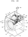
- FIG. 1 B is a perspective view illustrating a configuration in which a heat pump module is disposed above a tub.
- a cylindrical tub 17 is provided within the cabinet 10.
- An opening communicating with the opening of the front cover 10d is formed on a front side of the tub 17 to allow laundry and a dry target to be taken in and out.
- a hollow part may be provided within the tub 17 to store washing water.
- a gasket 17a extends from the opening of the tub 17 to the opening of the front cover 10d in a circumferential direction to prevent leakage of washing water kept in the tub 17 to outside and prevent transmission of vibration generated in the tub 17 to the cabinet 10 when the drum 18 is rotated.
- the gasket 17a may be formed of a vibration insulating member such as rubber.
- An air outlet is formed on upper rear side of the tub 17 to allow air to be discharged from the tub 17.
- An air inlet is formed in an upper portion of the gasket 17a of the tub 17 to allow air to be introduced to the tub 17.
- a cylindrical drum 18 is rotatably provided within the tub 17.
- the drum 18 has an accommodation space for accommodating laundry and a dry target therein, and has an opening formed on a front side of the drum 18 and communicating with the opening of the tub 17.
- the drum 18 has a plurality of through holes formed on an outer circumferential surface thereof to allow washing water and air to pass through the through holes between the drum 18 and the tub 17.
- a lifter is installed at an interval in a circumferential direction within the drum 18, to tumble laundry introduced to the inside of the drum 18.
- washing water supplied to the tub 17 is introduced to the inside of the drum 18 through the through holes, and when the drum 18 is rotated, the laundry introduced to the inside of the drum 18 is wet to be washed.
- hot air supplied to the inside of the tub 17 is introduced to the inside of the drum 18 through the through holes, and as the drum 18 rotates, moisture of laundry introduced to the inside of the drum 18 is evaporated by hot air to dry the laundry.
- the heat pump module 100 integrally modularizes an evaporator 111, a compressor 113, a condenser 112, and an expansion valve 114 by the integral housing 120.
- a circulation fan 130 providing power to air and the vapor-liquid separator 115 separating a gas phase refrigerant and a liquid phase refrigerant may also be integrally installed by the integral housing 120.
- the modularized heat pump module 100 is disposed between an upper portion of the tub 17 and a top cover 10a.
- the integral housing 120 may include a heat exchange duct unit 121 accommodating the evaporator 111 and the condenser 112 and a compressor base part 122 supporting the compressor 113.
- the heat exchange duct unit 121 is disposed on a front side in an upper portion of the tub 17, accommodates and supports the heat exchanger 110 therein, and is connected to the tub 17 to serve as a circulation duct forming a circulation flow channel for circulating air.
- the heat exchanger 110 includes an evaporator 111 and a condenser 112, and the evaporator 111 and the condenser 112 may be installed within the heat exchange duct unit 121 and spaced apart from each other in a direction perpendicular to a rotation central line of the drum.
- the compressor base part 122 serves to support the compressor 113 disposed in a space between an upper portion of the tub 17 and a side corner of the cabinet 10.
- the integral housing 120 may be supported in a forward/backward direction by a front side of the cabinet 10, for example, a front frame 15, and an upper portion of the back cover 10e as a rear side of the cabinet 10.
- a front side of the heat exchange duct unit 121 is in contact with a rear surface of the front frame 15 and fastened by a fastening member such as a screw, or the like.
- a rear side of the compressor base part 122 is in contact with a front side of the back cover 10e and fastened by a fastening member such as a screw.
- the integral housing 120 may be disposed to be spaced apart from an upper outer circumferential surface of the tub 17 to prevent transmission of vibrations generated by the drum 18 when the drum 18 rotates, to the heat pump module 100 through the tub 17.
- a disposition space of a heat pump system may be compactly optimized.
- the heat pump module 100 intakes air discharged from the drum 18 and heat-exchanges it with the evaporator 111 to absorb heat from the air through the evaporator 111 and removes moistures in the air (dehumidification function of the heat pump module 100). Also, the heat pump module 100 heat-exchanges air discharged from the evaporator 111 with the condenser 112 to discharge heat from a refrigerant passing through the condenser 112 as air to be re-supplied to the inside of the tub through the condenser 112 (air heating function of the heat pump module 100).
- the heat pump module 100 includes a circulation fan 130 intaking air discharged from the drum 18.
- the circulation fan 130 may be accommodated and supported in the fan duct unit 124, and may be integrally coupled to the right side of the heat exchange duct unit 121 by the fan duct unit 124.
- the vapor-liquid separator 115 is installed in a vapor-liquid separator mounting part 123 and compactly disposed on the rear side of the heat exchange duct unit 121 above the tub 17.
- the vapor-liquid separator mounting part 123 is integrally formed between a rear side of the heat exchange duct unit 121 and the left side of the compressor base part 122.
- the vapor-liquid separator 115 is disposed between the evaporator 111 and the compressor 113, and may be connected to the evaporator 111 and the compressor by a refrigerant pipe.
- the vapor-liquid separator has a cylindrical shape.
- the vapor-liquid separator according to the present disclosure may be compactly disposed even in a narrow space above the tub 17, and a inlet 1151a1 and a outlet 1151 a2 may be formed on the same side in order to avoid interference with other component.
- the inlet 1151a1 and the outlet 1151 a2 may be disposed to face each other toward the evaporator 111 of the heat exchange duct unit 121.
- the horizontal vapor-liquid separator 115 is horizontally disposed so as to be positioned to be lower than a height of the compressor 113.
- a control unit controls a general operation of the clothes treatment apparatus, as well as the heat pump module 100.
- the control unit may include a PCB case having a flat rectangular box shape in which a height thereof is lower than a width and a length thereof, a PCB installed within the PCB case 19, and electric/electronic control components installed in the PCB.
- FIG. 1C is a rear perspective view illustrating a fixing structure of a PCB case of FIG. 1B .
- the PCB case 19 may be disposed on a left side of the heat pump module 100 in a diagonal direction (when viewed from the front cover 10d) by using a space between the upper side of the tub 17 and the left side corner of the cabinet 10.
- the PCB case 19 As for the PCB case 19, a width of the PCB case 19 is longer than a space between the center above the tub 17 and the left side cover 10b. Thus, in order to avoid interference of the PCB case 19 with other components and compactly configure the PCB case 19 together with the heat pump module 100, the PCB case 19 is preferably disposed in a downward direction of the left side from a central upper portion of the cabinet 10 when viewed from the front cover 10d.
- the left side of the heat pump module 100 is positioned between the central upper portion of the cabinet 10 and the upper side of the tub 17 and a space from the left side corner of the cabinet 10 in a downward direction is larger than a space between the central upper portion of the cabinet 10 and the upper side of the tub 17, and thus, the PCB case 19 is disposed in a diagonal direction such that a right side thereof is disposed to face the left side of the heat pump module 100 and a left side of the PCB case 19 is disposed to face the left side cover 10b of the cabinet 10.
- the PCB case 19 may have a fixing protrusion 191 protruding from one side of an upper surface of the PCB case 19.
- An upper end portion of the fixing protrusion 191 may have a hook shape.
- the cabinet 10 may have a fixing member 192 extending from one side of an upper end portion of the front cover 10d to one side of an upper end portion of the back cover 10e in order to support the PCB case 19. Since the upper end portion of the fixing protrusion 191 is supported to be caught on the side surface of the fixing member 192, the PCB case 19 may be stably supported between the left side corner of the cabinet 10 and the heat pump module 100 and compactly disposed.
- the PCB case 19 is electrically connected to the heat pump module 100, and thus, performance of the heat pump module 100 may be inspected in units of modules before a complete product of the clothes treatment apparatus is assembled.
- the PCB case 19 is connected to the heat pump module 100 for performance inspection of the heat pump module 100, the PCB case 19 is preferably positioned to be close to the heat pump module 100.
- the PCB case 19 is disposed in a diagonal direction to be close on the side surface of the heat pump module 100 and connected to the heat pump module 100, the PCB case 19 may be compactly installed within the cabinet 10 together with the heat pump module 100.
- the compressor 113 may be disposed in the following structure to compactly effectively utilize a space above the tub 17.
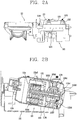
- FIG. 2A is a side view of a compressor of FIG. 1 B , viewed from the right side, and FIG. 2B is a cross-sectional view of the compressor of FIG. 2A .
- the compressor 113 may be provided as a horizontal compressor 113.
- the horizontal compressor 113 may have an electric mechanism unit 113a and a compression mechanism unit 113b together within a compressor casing 113c and may be disposed to be parallel to a support surface.
- the compressor 113 may be disposed to lie down extendedly in a forward/backward direction of the cabinet 10.
- the compressor 113 may be disposed such that an outer circumferential surface thereof faces in vertical and horizontal directions and a front surface and a rear surface thereof face a front surface and a rear surface of the cabinet 10, respectively.
- the horizontal compressor 113 is provided such that a lower surface of the compressor base part 122, a support surface, is inclined with respect to a horizontal plane.
- the horizontal compressor 113 is installed such that a rear portion of the compressor casing 113c is inclined downwardly with respect to a horizontal plane, allowing oil to gather in a side bearing of the compression mechanism unit 113b.
- an oil intake hole 1151a1 for intaking oil is immersed in oil all the time, and thus, oil may be smoothly supplied to the side bearing of the compression mechanism unit 113b.
- a slope angle of the compressor 113 is ranges from 3° to 20° with respect to a horizontal line.
- the electric mechanism unit 113a is integrally provided within the compressor 113 to provide a rotational force.
- the electric mechanism unit 113a may include a stator 113a1 fixed to the compressor casing 113c, a rotor 113a2 disposed within the stator 113a1, and a rotational shaft 113d press-fit to the inside of the rotor 113a2.
- the rotational shaft 113d may be disposed along a horizontal central line of the compressor casing 113c.
- the rotational shaft 113d is supported by a main bearing 113b3 and a sub-bearing 113b4.
- the compressor 113 may be provided as a rotary compressor 113.
- the compressor 113 may have a compression mechanism unit 113b.
- the compression mechanism unit 113b may include a cylinder 113b1 and a rolling piston 113b2.
- the rolling piston 113b2 may be eccentrically coupled to an outer circumferential surface of the rotational shaft 113d and compress a refrigerant, while rotating along an inner circumferential surface of the cylinder 113b1.
- the main bearing 113b3 and the sub-bearing 113b4 allow a relative movement between the cylinder 113b1 and the rotational shaft 113d or between the cylinder 113b1 and the rolling piston 113b1.
- An oil supply unit includes an oil cap 113b5 communicating with an end portion of an oil flow channel of the rotational shaft 113d, covering an outer surface of the sub-bearing 113b4, and having an oil accommodation space therein, an oil guide pipe 113b6 communicating with the oil cap 113b5, extending to a lower surface of the casing, and intaking oil of the lower surface of the casing to the oil cap 113b5, and an oil collecting pipe 113b7 communicating with a lower surface of the oil cap 113b5 and collecting oil to a lower surface of the casing.
- the rotor 113a2 when power is applied to the stator 113a1 of the motor part 113a, the rotor 113a2 is rotated according to an interaction with the stator 113a1, and the rotational shaft 113d coupled to the rotor 113a2 is rotated to transmit rotational force to the rolling piston 113b2 of the compression part 113b.
- a refrigerant is sucked into the suction chamber of the cylinder 113b1, is continuously compressed to predetermined pressure, moves to a high pressure portion of the casing, and subsequently moves to a heat pump cycle through an outlet 1134 formed on a front surface of the casing.
- oil at a low pressure portion is sucked to the oil cap 113b5 through the oil guide pipe 113b6, and the oil moves along an oil flow channel of the rotational shaft 113d and is supplied between the rolling piston 113b2 as a sliding portion of the compression part 113b and the cylinder 113b1 through an oil hole, thus performing a lubricating operation.
- the compression mechanism unit 113b may be positioned on a front side of the compression casing 113c, the electric mechanism unit 113a may be positioned on a rear side of the compression casing 113c, and the side bearing of the compression mechanism unit is disposed to be sloped downwardly, whereby oil may be sufficiently supplied to the side bearing of the compression mechanism unit 113b.
- the refrigerant outlet 1134 of the compressor 113 may be formed on a front side of the compression casing 113c to face the front frame 15 of the cabinet 10 or the circulation fan 130, and a refrigerant inlet 1151a1 of the compressor 113 may be formed on a lower side of an outer circumferential surface of the compressor casing 113c.
- a vibration-proof mount 1132 is provided on the compressor base part 122 to absorb vibrations of the compressor 113.
- the fixed bracket 1131 are welded to at least three positions so as to be fixed to an upper portion of the compressor 113 and cover a portion of an upper outer circumferential surface of the compressor 113. The fixed bracket 1131 transfers vibrations of the compressor 113 to the vibration-proof mount 1132.
- the fixed bracket 1131 and the vibration-proof mount 1132 are fixed to an upper portion of a support formed on a side surface of the compressor base part 122 by a fastening bolt.
- FIG. 3A is a perspective view illustrating a vapor-liquid separator of FIG. 1 B
- FIG. 3B is a front view of the vapor-liquid separator of FIG. 3A , viewed from the front side
- FIG. 4 is a cross-sectional view of FIG. 3B , taken along line A-A.
- FIG. 3A illustrates an appearance of the horizontal vapor-liquid separator 115 according to the present disclosure.
- the horizontal vapor-liquid separator 115 is compactly disposed in an internal space of the cabinet 10 together with the compressor 113, in particular, between an upper portion of the tub and an upper surface of the cabinet 10.
- the horizontal vapor-liquid separator 115 is disposed such that a front side thereof is laid down to face a front side of the cabinet 10.
- the front side of the horizontal vapor-liquid separator 115 refers to a side seen when the horizontal vapor-liquid separator 115 is viewed at a front side of the cabinet 10.
- a front side of the vapor-liquid separator 115 may face a rear side of the heat exchange duct unit 121.
- the compressor 113 and the vapor-liquid separator 115 may be installed and the vapor-liquid separator 115 may be compactly disposed together with the compressor 113.
- the horizontal vapor-liquid separator 115 includes a cylindrical casing 1151.
- An outer circumferential surface (circular curved surface) of the casing 1151 may be disposed to face in vertical and horizontal directions of the cabinet 10.
- a front side and a rear side of the casing 1151 may be formed as a flat surfaces, and a inlet and a outlet are formed on a front side of the casing. The inlet and outlet protrude in the same direction.
- a volume space having a predetermined size is provided within the casing 1151.
- the cylindrical casing 1151 illustrated in FIG. 4 may include a first casing 1151 a and a second casing 1151b having a cylindrical shape.
- the first casing 1151 a may be disposed on the left side and the second casing 1151b may be disposed on the right side, facing each other, and end portions of the first casing 1151 a and the second casing 1151b may be assembled in an overlapping manner in a thickness direction to form an airtight space within the casing 1151.
- a inlet 1151a1 and a outlet 1151 a2 are formed on a left side (front side of the casing in FIG. 3B ) of the first casing 1151a.
- the inlet 1151a1 is formed in an upper portion of a left side of the first casing 1151a
- the outlet 1151 a2 is formed in a lower portion of the left side of the first casing 1151 a in order to discharge a refrigerant to the outside of the casing 1151.
- the inlet 1151a1 is formed at an upper end portion of the front side of the casing 1151, and the outlet 1151a2 is formed at a lower end portion of the front side of the casing 1151.
- the inlet 1151a1 of the vapor-liquid separator 115 is connected to a outlet of the evaporator by a suction pipe 1152, and the outlet 1151a2 of the vapor-liquid separator 115 is connected to an inlet of the compressor 113 by a discharge pipe 1153.
- a first partition 1155 and a second partition 1156 are disposed to be spaced apart from each other in a length direction within the casing 1151 to divide an internal space of the casing 1151 into three sections.
- the first partition 1155 is disposed within the first casing 1151a
- the second partition 1156 is disposed within the second casing 1151b. Both end portions of the first partition 1155 and the second partition 1156 are bent by a predetermined length and press-fit to the inside of the first casing 1151 a and the second casing 1151b to reinforce strength of the casing 1151.
- the first partition 1155 is disposed to be parallel to the left side of the first casing 1151a
- the second casing 1156 is disposed to be parallel to the right side of the second casing 1151b.
- the first partition 1155 and the second partition 1156 are disposed in a direction perpendicular to an outer circumferential surfaces of the first and second casings 1151 a and 1151 b.
- the first partition 1155 may be disposed to be adjacent to the left side of the first casing 1151a, and the second partition 1156 may be disposed to be adjacent to the right side of the second casing 1151 b.
- an internal space partitioned between the first partition 1155 and the second partition 1156 is a liquid storage part 1151 c1 storing a liquid.
- a liquid phase refrigerant or oil may be temporarily stored in the liquid storage part 1151 c1.
- a first internal space partitioned between a left side of the first casing 1151 a and the first partition 1155 may form a flow channel for discharging a gas phase refrigerant
- a second internal space partition between a right side of the second casing 1151b and the second partition 1156 may form a return flow channel 1151 c3 for returning a mixture of a gas phase refrigerant, a liquid phase refrigerant, and oil.
- the suction pipe 1152 extends from a front side of the casing 1151 (the left side of the casing 1151 a in FIG. 4 ) to an internal space of the casing 1151 through the inlet 1151a1 and penetrates through the first partition 1155 and the second partition 1156. Accordingly, a mixture of a gas phase refrigerant, a liquid phase refrigerant, oil, and the like, introduced through the suction pipe 1152 is independently separated, without being mixed with other fluid, and introduced to the return flow channel 1151c3 formed between the second partition 1156 and the right side of the casing 1151.
- the suction pipe 1152 is disposed to be parallel to an outer circumferential surface of the casing 1151.
- a return hole 1156a is formed below the second partition 1156 and connects the return flow channel 1151c3 between the second partition 1156 and the right side of the casing 1151 and the liquid storage part 1151 c1.
- a refrigerant mixture introduced along the suction pipe 1152 is returned to the liquid storage part 1151 c1 through the return hole 1156a.
- a diameter of the return hole 1156a may be within a range of 1/3 to 3/4 of a height of the second partition. The reason for forming the return hole 1156a to be large is to secure a large suction and return amount of a refrigerant mixture fluid which has passed through the suction pipe 1152.
- a liquid phase refrigerant and oil stored in the liquid storage part 1151 c1 may be moved to the return flow channel 1151c3 through the return hole 1156a.
- the filter unit 1154 may have a net shape, and may be formed of a material such as a metal having a predetermined strength to maintain a predetermined shape.
- a hole formed in the net may have a fine size, for example, a size of a few to hundreds of ⁇ m.
- the filter unit 1154 may filter out a foreign object such as an iron particle, or the like, having a size ranging from 0.01 mm to 1 mm generated in the compressor, the evaporator, and the like.
- the net When the net is formed of thread, a polymer resin, and the like, it may have a separate frame to maintain a predetermined shape.
- the filter unit 1154 is configured to surround a circumference of the return hole 1156a to filter out and remove all the foreign objects included in a returned refrigerant mixture fluid.
- the filter unit 1154 may form a curved surface protruding from the second partition 1156 toward the first partition 1155, rather than a planar shape.
- the filter unit 1154 may include an installation part 1154a configured as an annular shape, a sloped portion 1154b slantingly extending from an end portion of the installation portion 1154a, and a connection portion 1154c extending in a vertical direction from an end portion of the sloped portion 1154b.
- the installation part 1154a of the filter unit 1154 may be fixed to the second partition 1156 through welding, or the like. Also, the installation part 1154a of the filter unit 1154 may be insertedly coupled to the second partition 1156 in an insertion manner.
- the second partition 1156 includes an annular filter fixing part 1156b for a connection to the filter unit 1154.
- FIG. 5 is a cross-sectional view of FIG. 4 , taken along line B-B.
- a communication hole 1155a has a rectangular shape in which a length is long in a horizontal direction in an upper portion of the first partition 1155.
- the suction pipe 1152 may penetrate through the first partition 1155 through the communication hole 1155a.
- the communication hole 1155a is a hole for a gas phase refrigerant separated in the liquid storage space to move to the first internal space.
- a vertical length of the communication hole 1155a is substantially the same as a diameter of the suction pipe 1152, and a horizontal length of the communication hole 1155a is longer than a diameter of the suction pipe 1152, so that a gas phase refrigerant may move to the discharge flow channel 1151c2 through the communication hole 1155a, without being mixed with a gas/liquid phase refrigerant mixture, and may be moved to the compressor 113 through the outlet 1151 a2 and the discharge pipe 1153 connected to the outlet 1151 a2.
- a refrigerant of the heat pump module 100 includes a portion of oil stored in the compressor 113 in the process of being compressed by the compressor 113, and may circulate to the compressor 113, the condenser 112, the expansion valve, and the evaporator 111.
- the liquid-phase separator 115 may separate oil from the liquid phase refrigerant and return the oil to the compressor 113.
- a plurality of oil return holes 1155b are formed on the first partition 1155.
- the oil return hole 1155b may be spaced apart from a lower end of the first partition 1155 in an upward direction.
- Oil stored in the liquid storage part 1151 c1 has specific gravity grater than that of a liquid phase refrigerant, and thus, oil may sink to be lower than the liquid phase refrigerant, and oil has a high possibility of being returned through the oil return hole 1155b positioned at the lowermost stage of the plurality of oil return holes 1155b.
- the oil return hole 1155b is very small, ranging from 1 mm to 3 mm, for example.
- the oil return hole 1155b since it is very small, it is evaporated.
- the gas phase refrigerant and oil are not mixed with each other.
- the casing 1151 may be disposed such that a front side is lower than a rear side (the right side in FIG. 4 ) thereof.
- the casing 1151 may be disposed to be downwardly sloped toward the discharge pipe 1153 with respect to the top cover 10a of the cabinet 10. This is to allow oil to easily gather to the outlet 1151a2 of the casing 1151 from the liquid storage part 1151 c1 by gravitation, to thereby increase a return amount of oil through the oil return hole 1155b.
- the configuration and method according to the embodiments of the present disclosure described above are not limited in its application, but the entirety or a portion of the embodiments may be selectively combined to be configured into various modifications.
Landscapes
- Engineering & Computer Science (AREA)
- Chemical & Material Sciences (AREA)
- Physics & Mathematics (AREA)
- Thermal Sciences (AREA)
- Analytical Chemistry (AREA)
- Power Engineering (AREA)
- Mechanical Engineering (AREA)
- General Engineering & Computer Science (AREA)
- Textile Engineering (AREA)
- Chemical Kinetics & Catalysis (AREA)
- Detail Structures Of Washing Machines And Dryers (AREA)
Abstract
Description
- The present disclosure relates to a vapor-liquid separator separating a gas phase refrigerant and a liquid phase refrigerant and a clothes treating apparatus having the same.
- In general, a heat pump system circulates a refrigerant through an evaporator, a compressor, a condenser, and an expansion valve, and the evaporator absorbs a heat source and the condenser discharges the heat source. Here, the refrigerant absorbs the heat source so as to be changed from a liquid phase to a vapor phase (or a gas phase), and discharges the heat source so as to be changed from the vapor phase to a liquid phase. The gas phase refrigerant is compressed by the compressor and subsequently circulates the condenser, the expansion valve, the evaporator, and the compressor as one cycle.
- If a liquid phase refrigerant is introduced together with a vapor phase refrigerant to the compressor, while the compressor operates, the liquid phase refrigerant is compressed, causing damage to the compressor.
- Thus, in order to prevent this, a vapor-liquid separator (or an accumulator) is connected to a inlet side of the compressor to separate the liquid phase refrigerant and the vapor phase refrigerant.
-
FIG. 6 is a perspective view illustrating a related art vapor-liquid separator. - As illustrated in
FIG. 6 , a vapor-liquid separator 1 includes arefrigerant inlet pipe 2a provided at an upper portion of thecasing 2 to allow a refrigerant discharged from the evaporator to be introduced to the inside of thecasing 2, includes arefrigerant discharge pipe 2b provided in a lower portion of thecasing 2 to discharge a gas phase refrigerant separated due to a difference in specific gravity of the refrigerant to the compressor, and stores the liquid phase refrigerant separated from the gas phase refrigerant in thecasing 2. - However, since the related art vapor-
liquid separator 1 is manufactured to be connected to a inlet side of a vertical compressor, it may not be applied to a horizontal compressor advantageously used when a height of an installation space of a compressor is small. If the vapor-liquid separator 1 illustrated inFIG. 6 is connected to a inlet side of the horizontal compressor, the vapor-liquid separator 1 may protrude upwardly from the horizontal compressor, causing a problem that an overall height of the compressor and the vapor-liquid separator 1 is increased against what was intended in the horizontal compressor. - In order to solve the problem,
US 4,776,183 discloses a horizontal accumulator disposed in a horizontal direction to be parallel to the horizontal compressor. - Meanwhile, in a case in which a heat pump system is applied to a clothes treating apparatus such as a washing machine, and the like, since a drum and a tub accommodating clothes, or the like, occupies the greatest part of an internal space of the clothes treating apparatus, a disposition space to install all of an evaporator, a condenser, a compressor, an expansion valve, a vapor-liquid separator, and the like, in the remaining space, excluding the drum and the tub, within the clothes treating apparatus is small.
- Here, as illustrated in
FIG. 7 , the horizontal accumulator ofUS 4,776,183 is not problematic when ainlet 37 and aoutlet 39 are positioned on the opposing sides, but in a case in which the horizontal accumulator ofUS 4,776,183 is disposed in a narrow space, it is possible to form theinlet 37 and theoutlet 39 on the same side or in the same direction to avoid interference with respect to other components, and even though theinlet 37 and theoutlet 39 are formed on the same side, the following problems arise. - For example, in the structure of the horizontal accumulator of
US 4,776,183 , in a case in which theinlet 37 and theoutlet 39 are positioned together on the left side, when a mixture of a liquid phase and gas phase refrigerant and oil introduced through a first communication opening 51 passes through an upper space of a liquid phase refrigerant storage space, the liquid phase refrigerant and oil are required to be separated and the gas phase refrigerant is required to be returned toward the outlet. However, since a hole allowing the gas phase refrigerant to be returned is not formed in asecond partition plate 47, the gas phase refrigerant is not able to be returned. - Here, even if a hold allowing the gas phase refrigerant to be returned is formed in the
second partition plate 47, the returned gas phase refrigerant meets the mixture including the sucked liquid phase refrigerant, or the like, causing a problem that it is impossible to separate the gas phase refrigerant and the liquid phase refrigerant, the intrinsic function of the vapor-liquid separator. - Therefore, an aspect of the invention is to provide a vapor-liquid separator which is compactly disposed within a cabinet in a small installation space and avoid interference with respect to an adjacent component, and a clothes treating apparatus having the same.
- Another aspect of the detailed description is to provide a vapor-liquid separator capable of separating a gas phase refrigerant and a liquid phase refrigerant although a inlet and a outlet are formed on the same side of a casing, and a clothes treating apparatus having the same.
- These objects are achieved with the features of the claims.
- The first object of the present disclosure may be achieved by horizontally disposing a vapor-liquid separator such that a central line in parallel to an outer circumferential surface passes through a front side and a rear side of a cabinet. Also, the second object may be achieved by forming an inlet and an outlet on the same side of a casing of the vapor-liquid separator.
- To achieve these objects, a vapor-liquid separator may include: a casing having an accommodation space therein; an inlet formed in the casing and allowing a refrigerant mixture fluid to be intaken to the accommodation space therethrough; and an outlet formed on the side of the inlet and allowing a gas phase refrigerant separated from the refrigerant mixture fluid to be discharged therethrough.
- The outlet may be formed to be spaced apart from the inlet on the same side, and the inlet may be formed in an upper portion of the same side, and the outlet may be disposed in a lower portion of the same side.
- The vapor-liquid separator may further include: a suction pipe extending to the accommodation space through the inlet.
- The vapor-liquid separator may include a first partition protruding from a lower surface of the casing in a direction perpendicular to an outer circumferential surface of the casing, facing the inlet and the outlet, and disposed to be spaced apart from the side on which the inlet and the outlet are formed.
- The accommodation space of the casing may be divided by the first partition into a discharge flow channel discharging the gas phase refrigerant and a liquid storage part providing a storage space of a liquid phase refrigerant and oil separated from the refrigerant mixture fluid.
- A communication hole connecting the discharge flow channel and the liquid storage part may be formed at an upper portion of the first partition.
- An oil return hole may be formed in the first partition, and oil discharged through the oil return hole may be collected by a compressor and a liquid phase refrigerant discharged through the oil return hole may be evaporated so as to be collected by the compressor.
- The vapor-liquid separator may include a second partition formed within the casing in a direction perpendicular to an outer circumferential surface of the casing, and disposed to be spaced apart from the side of the casing opposing the inlet and the outlet.
- The second partition may have a return hole forming a return flow channel of a refrigerant mixture fluid returned toward the outlet.
- The second partition may have a filter unit filtering out a foreign object included in the returned refrigerant mixture fluid.
- The filter unit may be provided such that one side thereof surrounds the return hole and the other side protrudes toward the outlet in the second partition.
- To achieve these objects, a vapor-liquid separator may include: a casing having an inlet and an outlet provided on the same side and having an accommodation space therein; a return flow channel formed within the casing to return a refrigerant mixture fluid toward the outlet in a direction opposite to a direction in which the refrigerant mixture fluid is intaken through the inlet; and a suction pipe extending from the inlet to the return flow channel.
- The return flow channel may be formed on the opposite side of the casing in a direction in which the refrigerant mixture fluid is intaken.
- The return flow channel may be formed by a second partition facing the opposite side of the casing and extending in a direction perpendicular to an outer circumferential surface of the casing.
- The second partition may have a return hole returning a refrigerant mixture fluid in a direction toward the outlet, and the return hole may be within a range of 1/3 to 3/4 of a length of the second partition.
- The second partition may include a filter unit filtering out a foreign object, while allowing a refrigerant mixture fluid returned through the return hole to pass therethrough.
- To achieve these objects, a vapor-liquid separator may include: a casing having an inlet and an outlet provided on the same side and having an accommodation space therein, wherein the casing is disposed such that a central line parallel to an outer circumferential surface is downwardly sloped toward the outlet with respect to a horizontal plane.
- The casing may include a first partition dividing a storage space of a liquid phase refrigerant and oil separated from a refrigerant mixture fluid intaken through the inlet and a discharge flow channel of a gas phase refrigerant.
- The first partition may have a plurality of oil return holes.
- To achieve these and other advantages and in accordance with the purpose of this specification, as embodied and broadly described herein, a vapor-liquid separator may include: a casing having an inlet and an outlet provided on one side in a direction in which a central line parallel to an outer circumferential surface passes, and having an accommodation space therein; and a second partition having a return flow channel formed on the opposite side of the casing in a direction in which the central line passes, in order to return a refrigerant mixture fluid in a direction opposite to a direction in which the refrigerant mixture fluid is intaken through the inlet.
- To achieve these objects, a vapor-liquid separator may include: a casing having an inlet and an outlet provided on one side in a direction in which a central line parallel to an outer circumferential surface passes, and having an accommodation space therein; a return flow channel formed on the opposite side of the casing in a direction in which the central line passes, in order to return a refrigerant mixture fluid in a direction opposite to a direction in which the refrigerant mixture fluid is intaken through the inlet; and a discharge flow channel formed on one side of the casing in a direction in which the central line passes, in order to allow the returned refrigerant mixture fluid to be discharged toward the outlet.
- The return flow channel and the discharge flow channel may face the inlet and the outlet and may be divided by a first partition formed in a direction perpendicular to an outer circumferential surface of the casing.
- To achieve these objects, a clothes treating apparatus may include: a cabinet; a drum rotatably provided within the cabinet and receiving laundry or a dry target; and a heat pump module circulating a refrigerant by an evaporator, a vapor-liquid separator, a compressor, a condenser, and an expansion valve, and circulating air discharged from the drum to the drum by way of the evaporator and the condenser, wherein the vapor-liquid separator includes a casing having an inlet and an outlet in a direction facing a side of the evaporator on the same side when viewed from a front side of the cabinet, and having an accommodation space therein.
- The casing may include a suction pipe extending from the inlet to the accommodation space and extending to a return flow channel of a refrigerant mixture fluid returned in a direction opposite to a direction in which the refrigerant is intaken through the inlet.
- The casing may be provided such that a front side thereof on which the inlet and the outlet are formed is positioned to be lower than a rear side thereof.
- The vapor-liquid separator according to the present disclosure configured as described above has the following advantages.
- First, since the vapor-liquid separator is disposed horizontally, although it is connected to an inlet of a horizontal compressor, an overall height of the compressor and the vapor-liquid separator is not increased.
- Second, since vapor and a liquid of a refrigerant are separated even though the inlet and the outlet are positioned together on one side of the casing of the vapor-liquid separator, interference with an adjacent component may be avoided.
- Third, when the vapor-liquid separator of the present disclosure is applied to a clothes treating apparatus, an internal space of a cabinet may be utilized to a maximum level and compactly optimized.
- Fourth, the suction pipe extends from one side of the casing of the vapor-liquid separator to an internal space of the casing to independently configure suction flow channel of a refrigerant intaken to the inside of the casing and a discharge flow channel of a refrigerant discharged to the outside of the casing, whereby an intaken liquid phase/gas phase mixture may be intake without being mixed with a gas phase refrigerant and only a gas phase refrigerant without a liquid phase refrigerant may be discharged through the communication hole.
- Fifth, the oil return hole is provided in the space in which the liquid phase refrigerant is stored, so that oil may be returned to the compressor.
- Further scope of applicability of the present application will become more apparent from the detailed description given hereinafter. However, it should be understood that the detailed description and specific examples, while indicating preferred embodiments of the invention, are given by way of illustration only, since various changes and modifications within the scope of the invention will become apparent to those skilled in the art from the detailed description.
- The accompanying drawings, which are included to provide a further understanding of the invention and are incorporated in and constitute a part of this specification, illustrate exemplary embodiments and together with the description serve to explain the principles of the invention.
- In the drawings:
-
FIG. 1A is a perspective view illustrating an implementation example of a clothes treating apparatus according to the present disclosure. -
FIG. 1 B is a perspective view illustrating a configuration in which a heat pump module according to the present disclosure is disposed above a tub. -
FIG. 1C is a rear perspective view illustrating a fixed structure of a PCB case ofFIG. 1B . -
FIG. 2A is a side view of a compressor ofFIG. 1 B , viewed from the right side, andFIG. 2B is a cross-sectional view of the compressor ofFIG. 2A . -
FIG. 3A is a perspective view illustrating a vapor-liquid separator ofFIG. 1 B . -
FIG. 3B is a front view of the vapor-liquid separator ofFIG. 3A , viewed from the front side. -
FIG. 4 is a cross-sectional view ofFIG. 3B , taken along line A-A. -
FIG. 5 is a cross-sectional view ofFIG. 4 , taken along line B-B. -
FIG. 6 is a perspective view illustrating a related art vapor-liquid separator -
FIG. 7 is a cross-sectional view illustrating a horizontal accumulator disclosed in Patent document D1. - Hereinafter, a vapor-liquid separator and a clothes treating apparatus having the same related to the present disclosure will be described in detail with reference to the accompanying drawings, in which like numbers refer to like elements throughout although the embodiments are different. As used herein, the singular forms "a", "an" and "the" are intended to include the plural forms as well, unless the context clearly indicates otherwise.
-
FIG. 1A is a perspective view illustrating an implementation example of a clothes treating apparatus according to the present disclosure. - A
cabinet 10 forms an external frame and an appearance of a clothes treatment apparatus. Thecabinet 10 may have a hexahedral shape. Thecabinet 10 may include atop cover 10a forming an upper surface of the hexahedron, aside cover 10b forming opposing sides of the hexahedron, abase cover 10c forming a lower surface of the hexahedron, afront cover 10d forming a front surface of the hexahedron, and aback cover 10e forming a rear surface of the hexahedron. - Here, an opening for introducing the laundry such as clothes, or the like, is formed on the
front cover 10d, and adoor 11 opening and closing the opening is provided. Thedoor 11 is coupled to afront cover 10d by a hinge on a left side of the opening and a right side of thedoor 11 may be rotated in a forward/backward direction. An automatic releasing device for automatically releasing the button type door may be provided on a right portion of thedoor 11 and on a right portion of the opening, so that when a right end portion of thedoor 11 is pushed to be closed, thedoor 11 is locked, and when theclosed door 11 is pressed once, thedoor 11 may be opened. - A
power button 12 may be provided on a right upper end of thefront cover 10d to turn on and off power of the clothes treatment apparatus. - A
display unit 13 and a touch type control panel may be formed on an upper end portion of thedoor 11. When a user performs a washing, spin-drying, or drying operation, an operational state of the clothes treatment apparatus may be visible to the user through thedisplay unit 13. Various functions may be selected or selected functions may be released through the touch type control panel. - A detergent supply unit may be provided between a lower side of the
tub 17 and thebase cover 10c and may be drawn out or inserted in a drawer manner. Alower cover 14 may be rotatably provided below thefront cover 10d in order to cover a front side of the detergent supply unit. -
FIG. 1 B is a perspective view illustrating a configuration in which a heat pump module is disposed above a tub. - A
cylindrical tub 17 is provided within thecabinet 10. An opening communicating with the opening of thefront cover 10d is formed on a front side of thetub 17 to allow laundry and a dry target to be taken in and out. A hollow part may be provided within thetub 17 to store washing water. Agasket 17a extends from the opening of thetub 17 to the opening of thefront cover 10d in a circumferential direction to prevent leakage of washing water kept in thetub 17 to outside and prevent transmission of vibration generated in thetub 17 to thecabinet 10 when the drum 18 is rotated. Thegasket 17a may be formed of a vibration insulating member such as rubber. An air outlet is formed on upper rear side of thetub 17 to allow air to be discharged from thetub 17. An air inlet is formed in an upper portion of thegasket 17a of thetub 17 to allow air to be introduced to thetub 17. - A cylindrical drum 18 is rotatably provided within the
tub 17. The drum 18 has an accommodation space for accommodating laundry and a dry target therein, and has an opening formed on a front side of the drum 18 and communicating with the opening of thetub 17. The drum 18 has a plurality of through holes formed on an outer circumferential surface thereof to allow washing water and air to pass through the through holes between the drum 18 and thetub 17. A lifter is installed at an interval in a circumferential direction within the drum 18, to tumble laundry introduced to the inside of the drum 18. For example, in a washing cycle, washing water supplied to thetub 17 is introduced to the inside of the drum 18 through the through holes, and when the drum 18 is rotated, the laundry introduced to the inside of the drum 18 is wet to be washed. Also, in a drying cycle, hot air supplied to the inside of thetub 17 is introduced to the inside of the drum 18 through the through holes, and as the drum 18 rotates, moisture of laundry introduced to the inside of the drum 18 is evaporated by hot air to dry the laundry. - The
heat pump module 100 integrally modularizes anevaporator 111, acompressor 113, acondenser 112, and an expansion valve 114 by theintegral housing 120. Acirculation fan 130 providing power to air and the vapor-liquid separator 115 separating a gas phase refrigerant and a liquid phase refrigerant may also be integrally installed by theintegral housing 120. - The modularized
heat pump module 100 is disposed between an upper portion of thetub 17 and atop cover 10a. - The
integral housing 120 may include a heatexchange duct unit 121 accommodating theevaporator 111 and thecondenser 112 and acompressor base part 122 supporting thecompressor 113. - The heat
exchange duct unit 121 is disposed on a front side in an upper portion of thetub 17, accommodates and supports theheat exchanger 110 therein, and is connected to thetub 17 to serve as a circulation duct forming a circulation flow channel for circulating air. Theheat exchanger 110 includes anevaporator 111 and acondenser 112, and theevaporator 111 and thecondenser 112 may be installed within the heatexchange duct unit 121 and spaced apart from each other in a direction perpendicular to a rotation central line of the drum. - The
compressor base part 122 serves to support thecompressor 113 disposed in a space between an upper portion of thetub 17 and a side corner of thecabinet 10. - The
integral housing 120 may be supported in a forward/backward direction by a front side of thecabinet 10, for example, afront frame 15, and an upper portion of theback cover 10e as a rear side of thecabinet 10. A front side of the heatexchange duct unit 121 is in contact with a rear surface of thefront frame 15 and fastened by a fastening member such as a screw, or the like. A rear side of thecompressor base part 122 is in contact with a front side of theback cover 10e and fastened by a fastening member such as a screw. - The
integral housing 120 may be disposed to be spaced apart from an upper outer circumferential surface of thetub 17 to prevent transmission of vibrations generated by the drum 18 when the drum 18 rotates, to theheat pump module 100 through thetub 17. - Also, since the
evaporator 111, thecompressor 113, thecondenser 112, the expansion valve, and the like, forming a heat pump cycle are integrated by theintegral housing 120, a disposition space of a heat pump system may be compactly optimized. - The
heat pump module 100 intakes air discharged from the drum 18 and heat-exchanges it with theevaporator 111 to absorb heat from the air through theevaporator 111 and removes moistures in the air (dehumidification function of the heat pump module 100). Also, theheat pump module 100 heat-exchanges air discharged from theevaporator 111 with thecondenser 112 to discharge heat from a refrigerant passing through thecondenser 112 as air to be re-supplied to the inside of the tub through the condenser 112 (air heating function of the heat pump module 100). - The
heat pump module 100 includes acirculation fan 130 intaking air discharged from the drum 18. Thecirculation fan 130 may be accommodated and supported in thefan duct unit 124, and may be integrally coupled to the right side of the heatexchange duct unit 121 by thefan duct unit 124. - The vapor-
liquid separator 115 is installed in a vapor-liquid separator mounting part 123 and compactly disposed on the rear side of the heatexchange duct unit 121 above thetub 17. The vapor-liquid separator mounting part 123 is integrally formed between a rear side of the heatexchange duct unit 121 and the left side of thecompressor base part 122. The vapor-liquid separator 115 is disposed between theevaporator 111 and thecompressor 113, and may be connected to theevaporator 111 and the compressor by a refrigerant pipe. The vapor-liquid separator has a cylindrical shape. The vapor-liquid separator according to the present disclosure, as a horizontal vapor-liquid separator 115, may be compactly disposed even in a narrow space above thetub 17, and a inlet 1151a1 and aoutlet 1151 a2 may be formed on the same side in order to avoid interference with other component. For example, the inlet 1151a1 and theoutlet 1151 a2 may be disposed to face each other toward theevaporator 111 of the heatexchange duct unit 121. The horizontal vapor-liquid separator 115 is horizontally disposed so as to be positioned to be lower than a height of thecompressor 113. - A control unit controls a general operation of the clothes treatment apparatus, as well as the
heat pump module 100. The control unit may include a PCB case having a flat rectangular box shape in which a height thereof is lower than a width and a length thereof, a PCB installed within thePCB case 19, and electric/electronic control components installed in the PCB. -
FIG. 1C is a rear perspective view illustrating a fixing structure of a PCB case ofFIG. 1B . - The
PCB case 19 may be disposed on a left side of theheat pump module 100 in a diagonal direction (when viewed from thefront cover 10d) by using a space between the upper side of thetub 17 and the left side corner of thecabinet 10. - As for the
PCB case 19, a width of thePCB case 19 is longer than a space between the center above thetub 17 and theleft side cover 10b. Thus, in order to avoid interference of thePCB case 19 with other components and compactly configure thePCB case 19 together with theheat pump module 100, thePCB case 19 is preferably disposed in a downward direction of the left side from a central upper portion of thecabinet 10 when viewed from thefront cover 10d. Here, the left side of theheat pump module 100 is positioned between the central upper portion of thecabinet 10 and the upper side of thetub 17 and a space from the left side corner of thecabinet 10 in a downward direction is larger than a space between the central upper portion of thecabinet 10 and the upper side of thetub 17, and thus, thePCB case 19 is disposed in a diagonal direction such that a right side thereof is disposed to face the left side of theheat pump module 100 and a left side of thePCB case 19 is disposed to face theleft side cover 10b of thecabinet 10. - In order to stably support the
PCB case 19 within thecabinet 10, thePCB case 19 may have a fixingprotrusion 191 protruding from one side of an upper surface of thePCB case 19. An upper end portion of the fixingprotrusion 191 may have a hook shape. Also, thecabinet 10 may have a fixingmember 192 extending from one side of an upper end portion of thefront cover 10d to one side of an upper end portion of theback cover 10e in order to support thePCB case 19. Since the upper end portion of the fixingprotrusion 191 is supported to be caught on the side surface of the fixingmember 192, thePCB case 19 may be stably supported between the left side corner of thecabinet 10 and theheat pump module 100 and compactly disposed. - The
PCB case 19 is electrically connected to theheat pump module 100, and thus, performance of theheat pump module 100 may be inspected in units of modules before a complete product of the clothes treatment apparatus is assembled. Here, since thePCB case 19 is connected to theheat pump module 100 for performance inspection of theheat pump module 100, thePCB case 19 is preferably positioned to be close to theheat pump module 100. - Thus, since the
PCB case 19 is disposed in a diagonal direction to be close on the side surface of theheat pump module 100 and connected to theheat pump module 100, thePCB case 19 may be compactly installed within thecabinet 10 together with theheat pump module 100. - Also, the
compressor 113 may be disposed in the following structure to compactly effectively utilize a space above thetub 17. -
FIG. 2A is a side view of a compressor ofFIG. 1 B , viewed from the right side, andFIG. 2B is a cross-sectional view of the compressor ofFIG. 2A . - The
compressor 113 may be provided as ahorizontal compressor 113. Thehorizontal compressor 113 may have anelectric mechanism unit 113a and acompression mechanism unit 113b together within acompressor casing 113c and may be disposed to be parallel to a support surface. Thecompressor 113 may be disposed to lie down extendedly in a forward/backward direction of thecabinet 10. Thecompressor 113 may be disposed such that an outer circumferential surface thereof faces in vertical and horizontal directions and a front surface and a rear surface thereof face a front surface and a rear surface of thecabinet 10, respectively. - Also, the
horizontal compressor 113 is provided such that a lower surface of thecompressor base part 122, a support surface, is inclined with respect to a horizontal plane. For example, thehorizontal compressor 113 is installed such that a rear portion of thecompressor casing 113c is inclined downwardly with respect to a horizontal plane, allowing oil to gather in a side bearing of thecompression mechanism unit 113b. Accordingly, an oil intake hole 1151a1 for intaking oil is immersed in oil all the time, and thus, oil may be smoothly supplied to the side bearing of thecompression mechanism unit 113b. Preferably, a slope angle of thecompressor 113 is ranges from 3° to 20° with respect to a horizontal line. - The
electric mechanism unit 113a is integrally provided within thecompressor 113 to provide a rotational force. Theelectric mechanism unit 113a may include a stator 113a1 fixed to thecompressor casing 113c, a rotor 113a2 disposed within the stator 113a1, and arotational shaft 113d press-fit to the inside of the rotor 113a2. Therotational shaft 113d may be disposed along a horizontal central line of thecompressor casing 113c. Therotational shaft 113d is supported by a main bearing 113b3 and a sub-bearing 113b4. - The
compressor 113 may be provided as arotary compressor 113. Thecompressor 113 may have acompression mechanism unit 113b. Thecompression mechanism unit 113b may include a cylinder 113b1 and a rolling piston 113b2. The rolling piston 113b2 may be eccentrically coupled to an outer circumferential surface of therotational shaft 113d and compress a refrigerant, while rotating along an inner circumferential surface of the cylinder 113b1. The main bearing 113b3 and the sub-bearing 113b4 allow a relative movement between the cylinder 113b1 and therotational shaft 113d or between the cylinder 113b1 and the rolling piston 113b1. - An oil supply unit includes an oil cap 113b5 communicating with an end portion of an oil flow channel of the
rotational shaft 113d, covering an outer surface of the sub-bearing 113b4, and having an oil accommodation space therein, an oil guide pipe 113b6 communicating with the oil cap 113b5, extending to a lower surface of the casing, and intaking oil of the lower surface of the casing to the oil cap 113b5, and an oil collecting pipe 113b7 communicating with a lower surface of the oil cap 113b5 and collecting oil to a lower surface of the casing. - Referring to an oil supply path of the
compressor 113, when power is applied to the stator 113a1 of themotor part 113a, the rotor 113a2 is rotated according to an interaction with the stator 113a1, and therotational shaft 113d coupled to the rotor 113a2 is rotated to transmit rotational force to the rolling piston 113b2 of thecompression part 113b. Here, as the rolling piston 113b2 eccentrically rotates in the internal space of the cylinder 113b1, a refrigerant is sucked into the suction chamber of the cylinder 113b1, is continuously compressed to predetermined pressure, moves to a high pressure portion of the casing, and subsequently moves to a heat pump cycle through anoutlet 1134 formed on a front surface of the casing. Here, oil at a low pressure portion is sucked to the oil cap 113b5 through the oil guide pipe 113b6, and the oil moves along an oil flow channel of therotational shaft 113d and is supplied between the rolling piston 113b2 as a sliding portion of thecompression part 113b and the cylinder 113b1 through an oil hole, thus performing a lubricating operation. - The
compression mechanism unit 113b may be positioned on a front side of thecompression casing 113c, theelectric mechanism unit 113a may be positioned on a rear side of thecompression casing 113c, and the side bearing of the compression mechanism unit is disposed to be sloped downwardly, whereby oil may be sufficiently supplied to the side bearing of thecompression mechanism unit 113b. - The
refrigerant outlet 1134 of thecompressor 113 may be formed on a front side of thecompression casing 113c to face thefront frame 15 of thecabinet 10 or thecirculation fan 130, and a refrigerant inlet 1151a1 of thecompressor 113 may be formed on a lower side of an outer circumferential surface of thecompressor casing 113c. - In order to reduce vibrations and noise generated in the
compressor 113, a vibration-proof mount 1132 is provided on thecompressor base part 122 to absorb vibrations of thecompressor 113. Also, the fixedbracket 1131 are welded to at least three positions so as to be fixed to an upper portion of thecompressor 113 and cover a portion of an upper outer circumferential surface of thecompressor 113. The fixedbracket 1131 transfers vibrations of thecompressor 113 to the vibration-proof mount 1132. - The fixed
bracket 1131 and the vibration-proof mount 1132 are fixed to an upper portion of a support formed on a side surface of thecompressor base part 122 by a fastening bolt. -
FIG. 3A is a perspective view illustrating a vapor-liquid separator ofFIG. 1 B ,FIG. 3B is a front view of the vapor-liquid separator ofFIG. 3A , viewed from the front side, andFIG. 4 is a cross-sectional view ofFIG. 3B , taken along line A-A. -
FIG. 3A illustrates an appearance of the horizontal vapor-liquid separator 115 according to the present disclosure. The horizontal vapor-liquid separator 115 is compactly disposed in an internal space of thecabinet 10 together with thecompressor 113, in particular, between an upper portion of the tub and an upper surface of thecabinet 10. For example, the horizontal vapor-liquid separator 115 is disposed such that a front side thereof is laid down to face a front side of thecabinet 10. The front side of the horizontal vapor-liquid separator 115 refers to a side seen when the horizontal vapor-liquid separator 115 is viewed at a front side of thecabinet 10. In a case in which the heat pump module is mounted above the tub, a front side of the vapor-liquid separator 115 may face a rear side of the heatexchange duct unit 121. Thus, when thecompressor 113 and the vapor-liquid separator 115 are viewed from theside cover 10b of thecabinet 10, a height of the vapor-liquid separator 115 does not protrude upwardly or downwardly from thecompressor 113, not increasing an overall height of the vapor-liquid separator 115 and thecompressor 113. Thus, even in a case in which an installation space of thecompressor 113 and the vapor-liquid separator 115 is narrow, thecompressor 113 and the vapor-liquid separator 115 may be installed and the vapor-liquid separator 115 may be compactly disposed together with thecompressor 113. - The horizontal vapor-
liquid separator 115 includes acylindrical casing 1151. An outer circumferential surface (circular curved surface) of thecasing 1151 may be disposed to face in vertical and horizontal directions of thecabinet 10. A front side and a rear side of thecasing 1151 may be formed as a flat surfaces, and a inlet and a outlet are formed on a front side of the casing. The inlet and outlet protrude in the same direction. A volume space having a predetermined size is provided within thecasing 1151. - The
cylindrical casing 1151 illustrated inFIG. 4 may include afirst casing 1151 a and asecond casing 1151b having a cylindrical shape. Thefirst casing 1151 a may be disposed on the left side and thesecond casing 1151b may be disposed on the right side, facing each other, and end portions of thefirst casing 1151 a and thesecond casing 1151b may be assembled in an overlapping manner in a thickness direction to form an airtight space within thecasing 1151. - A inlet 1151a1 and a
outlet 1151 a2 are formed on a left side (front side of the casing inFIG. 3B ) of thefirst casing 1151a. In order to suck a refrigerant to the inside of thecasing 1151, the inlet 1151a1 is formed in an upper portion of a left side of thefirst casing 1151a, and theoutlet 1151 a2 is formed in a lower portion of the left side of thefirst casing 1151 a in order to discharge a refrigerant to the outside of thecasing 1151. - The inlet 1151a1 is formed at an upper end portion of the front side of the
casing 1151, and the outlet 1151a2 is formed at a lower end portion of the front side of thecasing 1151. The inlet 1151a1 of the vapor-liquid separator 115 is connected to a outlet of the evaporator by asuction pipe 1152, and the outlet 1151a2 of the vapor-liquid separator 115 is connected to an inlet of thecompressor 113 by adischarge pipe 1153. - A
first partition 1155 and asecond partition 1156 are disposed to be spaced apart from each other in a length direction within thecasing 1151 to divide an internal space of thecasing 1151 into three sections. Thefirst partition 1155 is disposed within thefirst casing 1151a, and thesecond partition 1156 is disposed within thesecond casing 1151b. Both end portions of thefirst partition 1155 and thesecond partition 1156 are bent by a predetermined length and press-fit to the inside of thefirst casing 1151 a and thesecond casing 1151b to reinforce strength of thecasing 1151. Thefirst partition 1155 is disposed to be parallel to the left side of thefirst casing 1151a, and thesecond casing 1156 is disposed to be parallel to the right side of thesecond casing 1151b. Thefirst partition 1155 and thesecond partition 1156 are disposed in a direction perpendicular to an outer circumferential surfaces of the first andsecond casings first partition 1155 may be disposed to be adjacent to the left side of thefirst casing 1151a, and thesecond partition 1156 may be disposed to be adjacent to the right side of thesecond casing 1151 b. - Among the three internal spaces, an internal space partitioned between the
first partition 1155 and thesecond partition 1156 is aliquid storage part 1151 c1 storing a liquid. For example, a liquid phase refrigerant or oil may be temporarily stored in theliquid storage part 1151 c1. - Also, among the three internal spaces, a first internal space partitioned between a left side of the
first casing 1151 a and thefirst partition 1155 may form a flow channel for discharging a gas phase refrigerant, and a second internal space partition between a right side of thesecond casing 1151b and thesecond partition 1156 may form areturn flow channel 1151 c3 for returning a mixture of a gas phase refrigerant, a liquid phase refrigerant, and oil. - The
suction pipe 1152 extends from a front side of the casing 1151 (the left side of thecasing 1151 a inFIG. 4 ) to an internal space of thecasing 1151 through the inlet 1151a1 and penetrates through thefirst partition 1155 and thesecond partition 1156. Accordingly, a mixture of a gas phase refrigerant, a liquid phase refrigerant, oil, and the like, introduced through thesuction pipe 1152 is independently separated, without being mixed with other fluid, and introduced to the return flow channel 1151c3 formed between thesecond partition 1156 and the right side of thecasing 1151. Thesuction pipe 1152 is disposed to be parallel to an outer circumferential surface of thecasing 1151. - A
return hole 1156a is formed below thesecond partition 1156 and connects the return flow channel 1151c3 between thesecond partition 1156 and the right side of thecasing 1151 and theliquid storage part 1151 c1. Thus, a refrigerant mixture introduced along thesuction pipe 1152 is returned to theliquid storage part 1151 c1 through thereturn hole 1156a. A diameter of thereturn hole 1156a may be within a range of 1/3 to 3/4 of a height of the second partition. The reason for forming thereturn hole 1156a to be large is to secure a large suction and return amount of a refrigerant mixture fluid which has passed through thesuction pipe 1152. Also, it is to secure a storage space of a liquid phase refrigerant and oil as much as possible through thereturn hole 1156a. That is, a liquid phase refrigerant and oil stored in theliquid storage part 1151 c1 may be moved to the return flow channel 1151c3 through thereturn hole 1156a. - The
filter unit 1154 may have a net shape, and may be formed of a material such as a metal having a predetermined strength to maintain a predetermined shape. A hole formed in the net may have a fine size, for example, a size of a few to hundreds of µm. For example, thefilter unit 1154 may filter out a foreign object such as an iron particle, or the like, having a size ranging from 0.01 mm to 1 mm generated in the compressor, the evaporator, and the like. When the net is formed of thread, a polymer resin, and the like, it may have a separate frame to maintain a predetermined shape. Also, thefilter unit 1154 is configured to surround a circumference of thereturn hole 1156a to filter out and remove all the foreign objects included in a returned refrigerant mixture fluid. Thefilter unit 1154 may form a curved surface protruding from thesecond partition 1156 toward thefirst partition 1155, rather than a planar shape. Thefilter unit 1154 may include aninstallation part 1154a configured as an annular shape, a slopedportion 1154b slantingly extending from an end portion of theinstallation portion 1154a, and aconnection portion 1154c extending in a vertical direction from an end portion of the slopedportion 1154b. Theinstallation part 1154a of thefilter unit 1154 may be fixed to thesecond partition 1156 through welding, or the like. Also, theinstallation part 1154a of thefilter unit 1154 may be insertedly coupled to thesecond partition 1156 in an insertion manner. Thesecond partition 1156 includes an annularfilter fixing part 1156b for a connection to thefilter unit 1154. - While passing through the
filter unit 1154 from the liquid storage part 1151c1, a liquid phase refrigerant and oil having a specific gravity higher than that of the gas phase refrigerant sink to a lower surface of theliquid storage unit 1151 c1, while a gas phase refrigerant having a low specific gravity may be moved to an upper side of theliquid storage unit 1151 c1. -
FIG. 5 is a cross-sectional view ofFIG. 4 , taken along line B-B. - Referring to
FIG. 5 , acommunication hole 1155a has a rectangular shape in which a length is long in a horizontal direction in an upper portion of thefirst partition 1155. Thesuction pipe 1152 may penetrate through thefirst partition 1155 through thecommunication hole 1155a. Thecommunication hole 1155a is a hole for a gas phase refrigerant separated in the liquid storage space to move to the first internal space. A vertical length of thecommunication hole 1155a is substantially the same as a diameter of thesuction pipe 1152, and a horizontal length of thecommunication hole 1155a is longer than a diameter of thesuction pipe 1152, so that a gas phase refrigerant may move to the discharge flow channel 1151c2 through thecommunication hole 1155a, without being mixed with a gas/liquid phase refrigerant mixture, and may be moved to thecompressor 113 through theoutlet 1151 a2 and thedischarge pipe 1153 connected to theoutlet 1151 a2. - A refrigerant of the
heat pump module 100 includes a portion of oil stored in thecompressor 113 in the process of being compressed by thecompressor 113, and may circulate to thecompressor 113, thecondenser 112, the expansion valve, and theevaporator 111. Here, before the refrigerant is introduced to thecompressor 113 from theevaporator 111, the liquid-phase separator 115 may separate oil from the liquid phase refrigerant and return the oil to thecompressor 113. - In order to separate oil from the liquid phase refrigerant in the vapor-
liquid separator 115, a plurality ofoil return holes 1155b are formed on thefirst partition 1155. Theoil return hole 1155b may be spaced apart from a lower end of thefirst partition 1155 in an upward direction. - Oil stored in the
liquid storage part 1151 c1 has specific gravity grater than that of a liquid phase refrigerant, and thus, oil may sink to be lower than the liquid phase refrigerant, and oil has a high possibility of being returned through theoil return hole 1155b positioned at the lowermost stage of the plurality ofoil return holes 1155b. - Also, since the
oil return hole 1155b is very small, ranging from 1 mm to 3 mm, for example. Thus, even through a portion of the liquid phase refrigerant stored in theliquid storage unit 1151 c1 flows out through theoil return hole 1155b, since it is very small, it is evaporated. Here, the gas phase refrigerant and oil are not mixed with each other. - The
casing 1151 may be disposed such that a front side is lower than a rear side (the right side inFIG. 4 ) thereof. Thecasing 1151 may be disposed to be downwardly sloped toward thedischarge pipe 1153 with respect to thetop cover 10a of thecabinet 10. This is to allow oil to easily gather to the outlet 1151a2 of thecasing 1151 from theliquid storage part 1151 c1 by gravitation, to thereby increase a return amount of oil through theoil return hole 1155b. - As for the vapor-
liquid separator 115 and the clothes treating apparatus according to the present disclosure, the configuration and method according to the embodiments of the present disclosure described above are not limited in its application, but the entirety or a portion of the embodiments may be selectively combined to be configured into various modifications.
Claims (13)
- A vapor-liquid separator (115) comprising:a casing (1151) having an accommodation space therein;an inlet (1151a1) formed in the casing (1151) and allowing a refrigerant mixture fluid to be intaken to the accommodation space therethrough; andan outlet (1151a2) formed on the side of the inlet (1151) and allowing a gas phase refrigerant separated from the refrigerant mixture fluid to be discharged therethrough.
- The vapor-liquid separator of claim 1, wherein the outlet (1151a2) is formed to be spaced apart from the inlet (1151a1) on the same side of the casing (1151), and the inlet (1151a1) is formed in an upper portion of the same side, and the outlet (1151 a2) is disposed in a lower portion of the same side.
- The vapor-liquid separator of claim 1 or 2, further comprising:a suction pipe (1152) extending to the accommodation space through the inlet (1151a1).
- The vapor-liquid separator of claim 1, 2, or 3, further comprising:a first partition (1155) protruding from a lower surface of the casing (1151) in a direction perpendicular to an outer circumferential surface of the casing (1151), facing the inlet (1151a1) and the outlet (1151a2), and disposed to be spaced apart from the side on which the inlet (1151a1) and the outlet (1151a2) are formed.
- The vapor-liquid separator of claim 4, wherein the accommodation space of the casing (1151) is divided by the first partition (1155) into a discharge flow channel (1151c2) discharging the gas phase refrigerant and a liquid storage part providing a storage space of a liquid phase refrigerant and oil separated from the refrigerant mixture fluid.
- The vapor-liquid separator of claim 4, or 5, wherein a communication hole (1155a) connecting the discharge flow channel (1151c2) and the liquid storage part is formed at an upper portion of the first partition (1155).
- The vapor-liquid separator of claim 4, 5, or 6, wherein an oil return hole (1155b) is formed in the first partition (1155), and oil discharged through the oil return hole (1155b) is collected by a compressor (113), and a liquid phase refrigerant discharged through the oil return hole (1155b) is preferably evaporated so as to be collected by the compressor (113).
- The vapor-liquid separator of any one of claims 4 to 7, further comprising:a second partition (1156) formed within the casing (1151) in a direction perpendicular to an outer circumferential surface of the casing (1151), and disposed to be spaced apart from the side of the casing (1151) opposing the inlet (1151 a1) and the outlet (115a2).
- The vapor-liquid separator of claim 8, wherein the second partition (1156) has a return hole forming a return flow channel (1151 c3) of a refrigerant mixture fluid returned toward the outlet (1151a2).
- The vapor-liquid separator of claim 9, wherein the second partition (1156) has a filter unit (1154) filtering out a foreign object included in the returned refrigerant mixture fluid.
- The vapor-liquid separator of claim 10, wherein the filter unit (1154) is provided such that one side thereof surrounds the return hole and the other side protrudes toward the outlet (1151 a2).
- A clothes treating apparatus comprising:a cabinet (10);a drum (18) rotatably provided within the cabinet (10) and receiving laundry or a dry target; anda heat pump module (100) circulating a refrigerant by an evaporator (111), a vapor-liquid separator (115), a compressor (113), a condenser (112), and an expansion valve (114), and circulating air discharged from the drum (18) back to the drum (18) by way of the evaporator (111) and the condenser (112),wherein the vapor-liquid separator (115) includes a casing (1151) having an inlet (1151a1) and an outlet (1151a2) in a direction facing a side of the evaporator (111) on the same side when viewed from a front side of the cabinet (10), and having an accommodation space therein.
- The clothes treating apparatus of claim 12, wherein the casing (1151) is disposed such that a central line parallel to an outer circumferential surface is downwardly sloped toward the outlet (1151a2) with respect to a horizontal plane.
Applications Claiming Priority (1)
| Application Number | Priority Date | Filing Date | Title |
|---|---|---|---|
| KR1020160001191A KR102627101B1 (en) | 2016-01-05 | 2016-01-05 | Gas-liquid separator and clothes treatment apparatus having the gas-liquid separator |
Publications (2)
| Publication Number | Publication Date |
|---|---|
| EP3190360A1 true EP3190360A1 (en) | 2017-07-12 |
| EP3190360B1 EP3190360B1 (en) | 2025-03-19 |
Family
ID=57758423
Family Applications (1)
| Application Number | Title | Priority Date | Filing Date |
|---|---|---|---|
| EP16204928.2A Active EP3190360B1 (en) | 2016-01-05 | 2016-12-19 | Clothes treating apparatus comprising a vapor-liquid separator |
Country Status (8)
| Country | Link |
|---|---|
| US (1) | US10280545B2 (en) |
| EP (1) | EP3190360B1 (en) |
| JP (2) | JP2019502086A (en) |
| KR (1) | KR102627101B1 (en) |
| CN (1) | CN107059319B (en) |
| AU (1) | AU2016385262B2 (en) |
| RU (1) | RU2700601C1 (en) |
| WO (1) | WO2017119588A1 (en) |
Families Citing this family (9)
| Publication number | Priority date | Publication date | Assignee | Title |
|---|---|---|---|---|
| USD804113S1 (en) * | 2016-04-12 | 2017-11-28 | Whirlpool Corporation | Fabric care appliance |
| USD871689S1 (en) * | 2017-06-02 | 2019-12-31 | Samsung Electronics Co., Ltd. | Washing machine |
| USD867691S1 (en) * | 2017-06-02 | 2019-11-19 | Samsung Electronics Co., Ltd. | Washing machine |
| CN109722866A (en) * | 2017-10-30 | 2019-05-07 | 青岛海尔洗衣机有限公司 | A kind of cylinder structure and clothes dryer |
| WO2023017594A1 (en) * | 2021-08-12 | 2023-02-16 | 三菱電機株式会社 | Refrigerant storage container, and refrigeration cycle device provided with said refrigerant storage container |
| JP7642090B2 (en) * | 2021-10-28 | 2025-03-07 | 三菱重工サーマルシステムズ株式会社 | Transport refrigeration unit |
| CN115014012B (en) * | 2022-06-09 | 2023-05-23 | 珠海格力电器股份有限公司 | Fluorine pump compression refrigeration system and control method thereof |
| KR20240150917A (en) * | 2023-04-10 | 2024-10-17 | 삼성전자주식회사 | Filter assembly and clothes processing apparatus having the same |
| CN120466850B (en) * | 2025-05-19 | 2026-02-03 | 杭州华宏通信设备有限公司 | Air-cooled air conditioner capable of self-drying cool air |
Citations (5)
| Publication number | Priority date | Publication date | Assignee | Title |
|---|---|---|---|---|
| US4776183A (en) | 1987-02-06 | 1988-10-11 | Kabushiki Kaisha Toshiba | Lateral type accumulator |
| JPH02140571A (en) * | 1988-11-21 | 1990-05-30 | Toshiba Corp | Accumulator |
| US20030126883A1 (en) * | 2002-01-10 | 2003-07-10 | Mika Saito | Gas-liquid separator for ejector cycle |
| US20050217312A1 (en) * | 2004-04-02 | 2005-10-06 | Tekair Lp | Refrigerant receiving apparatus |
| US20120246960A1 (en) * | 2011-03-29 | 2012-10-04 | Lee Junseok | Clothes treating apparatus having heat exchanger cleaning device |
Family Cites Families (25)
| Publication number | Priority date | Publication date | Assignee | Title |
|---|---|---|---|---|
| US3791575A (en) * | 1971-08-30 | 1974-02-12 | Garrett Corp | Centrifugal separator discharge control system |
| JPS5384165U (en) * | 1976-12-13 | 1978-07-12 | ||
| US4139352A (en) * | 1978-03-14 | 1979-02-13 | Shell Oil Company | Gas liquid separator |
| SU1143945A1 (en) * | 1983-02-09 | 1985-03-07 | Ленинградский Ордена Трудового Красного Знамени Технологический Институт Холодильной Промышленности | Flooded-type evaporator |
| US4607503A (en) * | 1985-09-27 | 1986-08-26 | Tecumseh Products Company | Compressor mounted suction accumulator |
| US4683726A (en) * | 1986-07-16 | 1987-08-04 | Rejs Co., Inc. | Refrigeration apparatus |
| JPH0620056Y2 (en) * | 1987-12-29 | 1994-05-25 | ダイキン工業株式会社 | accumulator |
| RU2016368C1 (en) * | 1989-04-11 | 1994-07-15 | Товарас Николай Вячеславович | Submerged evaporator |
| CA2050981A1 (en) * | 1991-09-09 | 1993-03-10 | Earl Gingras | Three phase centrifugal separator |
| WO1999033570A1 (en) | 1997-12-25 | 1999-07-08 | Sharp Kabushiki Kaisha | Swing type gas-liquid separator and gas-liquid separation system |
| JP3690567B2 (en) * | 1998-09-04 | 2005-08-31 | シャープ株式会社 | Swivel gas-liquid separator |
| JP2002081802A (en) * | 2000-09-08 | 2002-03-22 | Hitachi Ltd | Air conditioner |
| KR100685756B1 (en) * | 2005-06-02 | 2007-02-22 | 주식회사 대우일렉트로닉스 | Accumulator with oil return line |
| JP2007255831A (en) * | 2006-03-24 | 2007-10-04 | Daikin Ind Ltd | Accumulator and refrigeration system |
| JP2008106964A (en) * | 2006-10-24 | 2008-05-08 | Daikin Ind Ltd | accumulator |
| CN201377946Y (en) * | 2009-04-03 | 2010-01-06 | 麦克维尔空调制冷(苏州)有限公司 | Labyrinth centrifugal oil-gas separator |
| EP2270274B2 (en) * | 2009-06-29 | 2022-01-12 | Electrolux Home Products Corporation N.V. | Appliance for drying laundry |
| AU2011358038B2 (en) * | 2011-01-31 | 2015-01-22 | Mitsubishi Electric Corporation | Air-conditioning apparatus |
| DE102012005197B3 (en) * | 2012-03-16 | 2013-06-13 | Iav Gmbh Ingenieurgesellschaft Auto Und Verkehr | Method for optimizing an internal combustion engine |
| JP2013226249A (en) * | 2012-04-25 | 2013-11-07 | Toshiba Corp | Clothes dryer |
| JP2013245917A (en) * | 2012-05-29 | 2013-12-09 | Panasonic Corp | Gas-liquid separator and refrigerating cycle device |
| CN202675764U (en) * | 2012-06-11 | 2013-01-16 | 珠海格力电器股份有限公司 | Horizontal gas-liquid separator and air conditioner compressor unit |
| JP6352614B2 (en) * | 2013-10-31 | 2018-07-04 | 東芝ライフスタイル株式会社 | Washing and drying machine |
| JP2015114060A (en) * | 2013-12-12 | 2015-06-22 | 三菱電機株式会社 | Accumulator and air conditioning device including the same |
| EP2886708B1 (en) * | 2013-12-20 | 2021-02-17 | BSH Hausgeräte GmbH | Washer-dryer |
-
2016
- 2016-01-05 KR KR1020160001191A patent/KR102627101B1/en active Active
- 2016-11-08 AU AU2016385262A patent/AU2016385262B2/en active Active
- 2016-11-08 RU RU2018128277A patent/RU2700601C1/en active
- 2016-11-08 JP JP2018534693A patent/JP2019502086A/en active Pending
- 2016-11-08 WO PCT/KR2016/012804 patent/WO2017119588A1/en not_active Ceased
- 2016-12-19 EP EP16204928.2A patent/EP3190360B1/en active Active
- 2016-12-20 CN CN201611186929.3A patent/CN107059319B/en active Active
-
2017
- 2017-01-03 US US15/397,161 patent/US10280545B2/en active Active
-
2022
- 2022-02-24 JP JP2022026436A patent/JP7296497B2/en active Active
Patent Citations (5)
| Publication number | Priority date | Publication date | Assignee | Title |
|---|---|---|---|---|
| US4776183A (en) | 1987-02-06 | 1988-10-11 | Kabushiki Kaisha Toshiba | Lateral type accumulator |
| JPH02140571A (en) * | 1988-11-21 | 1990-05-30 | Toshiba Corp | Accumulator |
| US20030126883A1 (en) * | 2002-01-10 | 2003-07-10 | Mika Saito | Gas-liquid separator for ejector cycle |
| US20050217312A1 (en) * | 2004-04-02 | 2005-10-06 | Tekair Lp | Refrigerant receiving apparatus |
| US20120246960A1 (en) * | 2011-03-29 | 2012-10-04 | Lee Junseok | Clothes treating apparatus having heat exchanger cleaning device |
Also Published As
| Publication number | Publication date |
|---|---|
| AU2016385262B2 (en) | 2019-11-07 |
| RU2700601C1 (en) | 2019-09-18 |
| US10280545B2 (en) | 2019-05-07 |
| CN107059319A (en) | 2017-08-18 |
| JP2019502086A (en) | 2019-01-24 |
| AU2016385262A1 (en) | 2018-07-12 |
| CN107059319B (en) | 2019-09-03 |
| JP7296497B2 (en) | 2023-06-22 |
| US20170191201A1 (en) | 2017-07-06 |
| KR20170082047A (en) | 2017-07-13 |
| JP2022078142A (en) | 2022-05-24 |
| KR102627101B1 (en) | 2024-01-22 |
| WO2017119588A1 (en) | 2017-07-13 |
| EP3190360B1 (en) | 2025-03-19 |
Similar Documents
| Publication | Publication Date | Title |
|---|---|---|
| EP3190360B1 (en) | Clothes treating apparatus comprising a vapor-liquid separator | |
| US10988894B2 (en) | Clothes treatment apparatus having heat pump module | |
| JP7026658B2 (en) | Garment processing equipment with heat pump module | |
| EP3190225B1 (en) | Clothes treating apparatus | |
| CN107675453B (en) | Clothes treating device | |
| EP3015590B1 (en) | Clothes treating apparatus comprising a compressor | |
| KR20180025094A (en) | Compressor and clothes treatment apparatus having the same | |
| RU2415217C1 (en) | Air conditioning device |
Legal Events
| Date | Code | Title | Description |
|---|---|---|---|
| PUAI | Public reference made under article 153(3) epc to a published international application that has entered the european phase |
Free format text: ORIGINAL CODE: 0009012 |
|
| STAA | Information on the status of an ep patent application or granted ep patent |
Free format text: STATUS: REQUEST FOR EXAMINATION WAS MADE |
|
| 17P | Request for examination filed |
Effective date: 20170119 |
|
| AK | Designated contracting states |
Kind code of ref document: A1 Designated state(s): AL AT BE BG CH CY CZ DE DK EE ES FI FR GB GR HR HU IE IS IT LI LT LU LV MC MK MT NL NO PL PT RO RS SE SI SK SM TR |
|
| AX | Request for extension of the european patent |
Extension state: BA ME |
|
| RBV | Designated contracting states (corrected) |
Designated state(s): AL AT BE BG CH CY CZ DE DK EE ES FI FR GB GR HR HU IE IS IT LI LT LU LV MC MK MT NL NO PL PT RO RS SE SI SK SM TR |
|
| STAA | Information on the status of an ep patent application or granted ep patent |
Free format text: STATUS: EXAMINATION IS IN PROGRESS |
|
| 17Q | First examination report despatched |
Effective date: 20210518 |
|
| RAP3 | Party data changed (applicant data changed or rights of an application transferred) |
Owner name: LG ELECTRONICS INC. |
|
| GRAP | Despatch of communication of intention to grant a patent |
Free format text: ORIGINAL CODE: EPIDOSNIGR1 |
|
| STAA | Information on the status of an ep patent application or granted ep patent |
Free format text: STATUS: GRANT OF PATENT IS INTENDED |
|
| INTG | Intention to grant announced |
Effective date: 20241024 |
|
| GRAJ | Information related to disapproval of communication of intention to grant by the applicant or resumption of examination proceedings by the epo deleted |
Free format text: ORIGINAL CODE: EPIDOSDIGR1 |
|
| STAA | Information on the status of an ep patent application or granted ep patent |
Free format text: STATUS: EXAMINATION IS IN PROGRESS |
|
| GRAS | Grant fee paid |
Free format text: ORIGINAL CODE: EPIDOSNIGR3 |
|
| STAA | Information on the status of an ep patent application or granted ep patent |
Free format text: STATUS: GRANT OF PATENT IS INTENDED |
|
| GRAP | Despatch of communication of intention to grant a patent |
Free format text: ORIGINAL CODE: EPIDOSNIGR1 |
|
| GRAA | (expected) grant |
Free format text: ORIGINAL CODE: 0009210 |
|
| STAA | Information on the status of an ep patent application or granted ep patent |
Free format text: STATUS: THE PATENT HAS BEEN GRANTED |
|
| INTC | Intention to grant announced (deleted) | ||
| INTG | Intention to grant announced |
Effective date: 20250210 |
|
| AK | Designated contracting states |
Kind code of ref document: B1 Designated state(s): AL AT BE BG CH CY CZ DE DK EE ES FI FR GB GR HR HU IE IS IT LI LT LU LV MC MK MT NL NO PL PT RO RS SE SI SK SM TR |
|
| REG | Reference to a national code |
Ref country code: GB Ref legal event code: FG4D |
|
| REG | Reference to a national code |
Ref country code: CH Ref legal event code: EP |
|
| REG | Reference to a national code |
Ref country code: DE Ref legal event code: R096 Ref document number: 602016091593 Country of ref document: DE |
|
| REG | Reference to a national code |
Ref country code: IE Ref legal event code: FG4D |
|
| PG25 | Lapsed in a contracting state [announced via postgrant information from national office to epo] |
Ref country code: RS Free format text: LAPSE BECAUSE OF FAILURE TO SUBMIT A TRANSLATION OF THE DESCRIPTION OR TO PAY THE FEE WITHIN THE PRESCRIBED TIME-LIMIT Effective date: 20250619 |
|
| PG25 | Lapsed in a contracting state [announced via postgrant information from national office to epo] |
Ref country code: FI Free format text: LAPSE BECAUSE OF FAILURE TO SUBMIT A TRANSLATION OF THE DESCRIPTION OR TO PAY THE FEE WITHIN THE PRESCRIBED TIME-LIMIT Effective date: 20250319 |
|
| REG | Reference to a national code |
Ref country code: LT Ref legal event code: MG9D |
|
| PG25 | Lapsed in a contracting state [announced via postgrant information from national office to epo] |
Ref country code: NO Free format text: LAPSE BECAUSE OF FAILURE TO SUBMIT A TRANSLATION OF THE DESCRIPTION OR TO PAY THE FEE WITHIN THE PRESCRIBED TIME-LIMIT Effective date: 20250619 |
|
| PG25 | Lapsed in a contracting state [announced via postgrant information from national office to epo] |
Ref country code: HR Free format text: LAPSE BECAUSE OF FAILURE TO SUBMIT A TRANSLATION OF THE DESCRIPTION OR TO PAY THE FEE WITHIN THE PRESCRIBED TIME-LIMIT Effective date: 20250319 |
|
| PG25 | Lapsed in a contracting state [announced via postgrant information from national office to epo] |
Ref country code: LV Free format text: LAPSE BECAUSE OF FAILURE TO SUBMIT A TRANSLATION OF THE DESCRIPTION OR TO PAY THE FEE WITHIN THE PRESCRIBED TIME-LIMIT Effective date: 20250319 |
|
| PG25 | Lapsed in a contracting state [announced via postgrant information from national office to epo] |
Ref country code: GR Free format text: LAPSE BECAUSE OF FAILURE TO SUBMIT A TRANSLATION OF THE DESCRIPTION OR TO PAY THE FEE WITHIN THE PRESCRIBED TIME-LIMIT Effective date: 20250620 Ref country code: BG Free format text: LAPSE BECAUSE OF FAILURE TO SUBMIT A TRANSLATION OF THE DESCRIPTION OR TO PAY THE FEE WITHIN THE PRESCRIBED TIME-LIMIT Effective date: 20250319 |
|
| REG | Reference to a national code |
Ref country code: NL Ref legal event code: MP Effective date: 20250319 |
|
| REG | Reference to a national code |
Ref country code: AT Ref legal event code: MK05 Ref document number: 1777240 Country of ref document: AT Kind code of ref document: T Effective date: 20250319 |
|
| PG25 | Lapsed in a contracting state [announced via postgrant information from national office to epo] |
Ref country code: NL Free format text: LAPSE BECAUSE OF FAILURE TO SUBMIT A TRANSLATION OF THE DESCRIPTION OR TO PAY THE FEE WITHIN THE PRESCRIBED TIME-LIMIT Effective date: 20250319 |
|
| PG25 | Lapsed in a contracting state [announced via postgrant information from national office to epo] |
Ref country code: SE Free format text: LAPSE BECAUSE OF FAILURE TO SUBMIT A TRANSLATION OF THE DESCRIPTION OR TO PAY THE FEE WITHIN THE PRESCRIBED TIME-LIMIT Effective date: 20250319 |
|
| PG25 | Lapsed in a contracting state [announced via postgrant information from national office to epo] |
Ref country code: SM Free format text: LAPSE BECAUSE OF FAILURE TO SUBMIT A TRANSLATION OF THE DESCRIPTION OR TO PAY THE FEE WITHIN THE PRESCRIBED TIME-LIMIT Effective date: 20250319 |
|
| PG25 | Lapsed in a contracting state [announced via postgrant information from national office to epo] |
Ref country code: ES Free format text: LAPSE BECAUSE OF FAILURE TO SUBMIT A TRANSLATION OF THE DESCRIPTION OR TO PAY THE FEE WITHIN THE PRESCRIBED TIME-LIMIT Effective date: 20250319 Ref country code: PT Free format text: LAPSE BECAUSE OF FAILURE TO SUBMIT A TRANSLATION OF THE DESCRIPTION OR TO PAY THE FEE WITHIN THE PRESCRIBED TIME-LIMIT Effective date: 20250721 |
|
| PG25 | Lapsed in a contracting state [announced via postgrant information from national office to epo] |
Ref country code: PL Free format text: LAPSE BECAUSE OF FAILURE TO SUBMIT A TRANSLATION OF THE DESCRIPTION OR TO PAY THE FEE WITHIN THE PRESCRIBED TIME-LIMIT Effective date: 20250319 Ref country code: IT Free format text: LAPSE BECAUSE OF FAILURE TO SUBMIT A TRANSLATION OF THE DESCRIPTION OR TO PAY THE FEE WITHIN THE PRESCRIBED TIME-LIMIT Effective date: 20250319 |
|
| PG25 | Lapsed in a contracting state [announced via postgrant information from national office to epo] |
Ref country code: AT Free format text: LAPSE BECAUSE OF FAILURE TO SUBMIT A TRANSLATION OF THE DESCRIPTION OR TO PAY THE FEE WITHIN THE PRESCRIBED TIME-LIMIT Effective date: 20250319 |
|
| PG25 | Lapsed in a contracting state [announced via postgrant information from national office to epo] |
Ref country code: CZ Free format text: LAPSE BECAUSE OF FAILURE TO SUBMIT A TRANSLATION OF THE DESCRIPTION OR TO PAY THE FEE WITHIN THE PRESCRIBED TIME-LIMIT Effective date: 20250319 Ref country code: EE Free format text: LAPSE BECAUSE OF FAILURE TO SUBMIT A TRANSLATION OF THE DESCRIPTION OR TO PAY THE FEE WITHIN THE PRESCRIBED TIME-LIMIT Effective date: 20250319 |
|
| PG25 | Lapsed in a contracting state [announced via postgrant information from national office to epo] |
Ref country code: RO Free format text: LAPSE BECAUSE OF FAILURE TO SUBMIT A TRANSLATION OF THE DESCRIPTION OR TO PAY THE FEE WITHIN THE PRESCRIBED TIME-LIMIT Effective date: 20250319 |
|
| PG25 | Lapsed in a contracting state [announced via postgrant information from national office to epo] |
Ref country code: SK Free format text: LAPSE BECAUSE OF FAILURE TO SUBMIT A TRANSLATION OF THE DESCRIPTION OR TO PAY THE FEE WITHIN THE PRESCRIBED TIME-LIMIT Effective date: 20250319 |
|
| PG25 | Lapsed in a contracting state [announced via postgrant information from national office to epo] |
Ref country code: IS Free format text: LAPSE BECAUSE OF FAILURE TO SUBMIT A TRANSLATION OF THE DESCRIPTION OR TO PAY THE FEE WITHIN THE PRESCRIBED TIME-LIMIT Effective date: 20250719 |
|
| REG | Reference to a national code |
Ref country code: DE Ref legal event code: R097 Ref document number: 602016091593 Country of ref document: DE |
|
| PGFP | Annual fee paid to national office [announced via postgrant information from national office to epo] |
Ref country code: DE Payment date: 20251105 Year of fee payment: 10 |
|
| PG25 | Lapsed in a contracting state [announced via postgrant information from national office to epo] |
Ref country code: DK Free format text: LAPSE BECAUSE OF FAILURE TO SUBMIT A TRANSLATION OF THE DESCRIPTION OR TO PAY THE FEE WITHIN THE PRESCRIBED TIME-LIMIT Effective date: 20250319 |
|
| PLBE | No opposition filed within time limit |
Free format text: ORIGINAL CODE: 0009261 |
|
| STAA | Information on the status of an ep patent application or granted ep patent |
Free format text: STATUS: NO OPPOSITION FILED WITHIN TIME LIMIT |
|
| REG | Reference to a national code |
Ref country code: CH Ref legal event code: L10 Free format text: ST27 STATUS EVENT CODE: U-0-0-L10-L00 (AS PROVIDED BY THE NATIONAL OFFICE) Effective date: 20260128 |
|
| 26N | No opposition filed |
Effective date: 20251222 |