EP3190284A1 - Engine control system, vehicle system, and engine control method - Google Patents
Engine control system, vehicle system, and engine control method Download PDFInfo
- Publication number
- EP3190284A1 EP3190284A1 EP15849093.8A EP15849093A EP3190284A1 EP 3190284 A1 EP3190284 A1 EP 3190284A1 EP 15849093 A EP15849093 A EP 15849093A EP 3190284 A1 EP3190284 A1 EP 3190284A1
- Authority
- EP
- European Patent Office
- Prior art keywords
- engine
- memory
- control
- unit
- memory information
- Prior art date
- Legal status (The legal status is an assumption and is not a legal conclusion. Google has not performed a legal analysis and makes no representation as to the accuracy of the status listed.)
- Granted
Links
- 238000000034 method Methods 0.000 title claims description 9
- 238000004891 communication Methods 0.000 claims description 54
- 238000012545 processing Methods 0.000 description 13
- 238000010586 diagram Methods 0.000 description 12
- 238000004364 calculation method Methods 0.000 description 4
- 239000000446 fuel Substances 0.000 description 4
- 238000002347 injection Methods 0.000 description 4
- 239000007924 injection Substances 0.000 description 4
- 239000013307 optical fiber Substances 0.000 description 4
- 230000006870 function Effects 0.000 description 3
- 238000013461 design Methods 0.000 description 2
- 238000012986 modification Methods 0.000 description 2
- 230000004048 modification Effects 0.000 description 2
- 230000008901 benefit Effects 0.000 description 1
- 230000005540 biological transmission Effects 0.000 description 1
- 230000000994 depressogenic effect Effects 0.000 description 1
- 230000000694 effects Effects 0.000 description 1
- 239000002184 metal Substances 0.000 description 1
- 230000009467 reduction Effects 0.000 description 1
- 230000004044 response Effects 0.000 description 1
- 239000000243 solution Substances 0.000 description 1
Images


Classifications
-
- F—MECHANICAL ENGINEERING; LIGHTING; HEATING; WEAPONS; BLASTING
- F02—COMBUSTION ENGINES; HOT-GAS OR COMBUSTION-PRODUCT ENGINE PLANTS
- F02D—CONTROLLING COMBUSTION ENGINES
- F02D41/00—Electrical control of supply of combustible mixture or its constituents
- F02D41/24—Electrical control of supply of combustible mixture or its constituents characterised by the use of digital means
- F02D41/2406—Electrical control of supply of combustible mixture or its constituents characterised by the use of digital means using essentially read only memories
- F02D41/2425—Particular ways of programming the data
- F02D41/2487—Methods for rewriting
-
- B—PERFORMING OPERATIONS; TRANSPORTING
- B60—VEHICLES IN GENERAL
- B60R—VEHICLES, VEHICLE FITTINGS, OR VEHICLE PARTS, NOT OTHERWISE PROVIDED FOR
- B60R16/00—Electric or fluid circuits specially adapted for vehicles and not otherwise provided for; Arrangement of elements of electric or fluid circuits specially adapted for vehicles and not otherwise provided for
- B60R16/02—Electric or fluid circuits specially adapted for vehicles and not otherwise provided for; Arrangement of elements of electric or fluid circuits specially adapted for vehicles and not otherwise provided for electric constitutive elements
-
- F—MECHANICAL ENGINEERING; LIGHTING; HEATING; WEAPONS; BLASTING
- F02—COMBUSTION ENGINES; HOT-GAS OR COMBUSTION-PRODUCT ENGINE PLANTS
- F02D—CONTROLLING COMBUSTION ENGINES
- F02D41/00—Electrical control of supply of combustible mixture or its constituents
- F02D41/0002—Controlling intake air
- F02D41/0007—Controlling intake air for control of turbo-charged or super-charged engines
-
- F—MECHANICAL ENGINEERING; LIGHTING; HEATING; WEAPONS; BLASTING
- F02—COMBUSTION ENGINES; HOT-GAS OR COMBUSTION-PRODUCT ENGINE PLANTS
- F02D—CONTROLLING COMBUSTION ENGINES
- F02D41/00—Electrical control of supply of combustible mixture or its constituents
- F02D41/0025—Controlling engines characterised by use of non-liquid fuels, pluralities of fuels, or non-fuel substances added to the combustible mixtures
- F02D41/0047—Controlling exhaust gas recirculation [EGR]
- F02D41/005—Controlling exhaust gas recirculation [EGR] according to engine operating conditions
- F02D41/0052—Feedback control of engine parameters, e.g. for control of air/fuel ratio or intake air amount
-
- F—MECHANICAL ENGINEERING; LIGHTING; HEATING; WEAPONS; BLASTING
- F02—COMBUSTION ENGINES; HOT-GAS OR COMBUSTION-PRODUCT ENGINE PLANTS
- F02D—CONTROLLING COMBUSTION ENGINES
- F02D41/00—Electrical control of supply of combustible mixture or its constituents
- F02D41/24—Electrical control of supply of combustible mixture or its constituents characterised by the use of digital means
- F02D41/26—Electrical control of supply of combustible mixture or its constituents characterised by the use of digital means using computer, e.g. microprocessor
- F02D41/266—Electrical control of supply of combustible mixture or its constituents characterised by the use of digital means using computer, e.g. microprocessor the computer being backed-up or assisted by another circuit, e.g. analogue
-
- F—MECHANICAL ENGINEERING; LIGHTING; HEATING; WEAPONS; BLASTING
- F02—COMBUSTION ENGINES; HOT-GAS OR COMBUSTION-PRODUCT ENGINE PLANTS
- F02D—CONTROLLING COMBUSTION ENGINES
- F02D2250/00—Engine control related to specific problems or objectives
- F02D2250/12—Timing of calculation, i.e. specific timing aspects when calculation or updating of engine parameter is performed
-
- F—MECHANICAL ENGINEERING; LIGHTING; HEATING; WEAPONS; BLASTING
- F02—COMBUSTION ENGINES; HOT-GAS OR COMBUSTION-PRODUCT ENGINE PLANTS
- F02D—CONTROLLING COMBUSTION ENGINES
- F02D41/00—Electrical control of supply of combustible mixture or its constituents
- F02D41/0025—Controlling engines characterised by use of non-liquid fuels, pluralities of fuels, or non-fuel substances added to the combustible mixtures
- F02D41/0047—Controlling exhaust gas recirculation [EGR]
-
- Y—GENERAL TAGGING OF NEW TECHNOLOGICAL DEVELOPMENTS; GENERAL TAGGING OF CROSS-SECTIONAL TECHNOLOGIES SPANNING OVER SEVERAL SECTIONS OF THE IPC; TECHNICAL SUBJECTS COVERED BY FORMER USPC CROSS-REFERENCE ART COLLECTIONS [XRACs] AND DIGESTS
- Y02—TECHNOLOGIES OR APPLICATIONS FOR MITIGATION OR ADAPTATION AGAINST CLIMATE CHANGE
- Y02T—CLIMATE CHANGE MITIGATION TECHNOLOGIES RELATED TO TRANSPORTATION
- Y02T10/00—Road transport of goods or passengers
- Y02T10/10—Internal combustion engine [ICE] based vehicles
- Y02T10/12—Improving ICE efficiencies
Definitions
- the present invention relates to an engine control system, a vehicle system, and an engine control method.
- an engine control system divided into an engine control unit (ECU) configured to control an engine body part and an ECU configured to control the turbocharger, the EGR, or the like is mounted.
- ECU engine control unit
- the ECUs which control the above-described devices constituting the engine need to control the engine body part, the turbocharger, the EGR, and the like in cooperation with one another, the amount of communication between the ECUs increases, and calculation loads of the ECUs tend to increase.
- the communication network is about to be constructed so as to prevent the occurrence of communication delay between the ECUs, the form of the communication network becomes complicated, and labor and cost required for designing the communication network increase.
- An object of the invention is to provide an engine control system, a vehicle system, and an engine control method capable of reducing a calculation load of each ECU while suppressing communication delay between ECUs.
- an engine control system includes a plurality of control devices which respectively have a plurality of engine units constituting an engine as a target to be controlled.
- Each of the plurality of control devices includes a drive control unit which controls the drive of the engine unit to be controlled according to memory information stored in a memory of the control device, a memory information output unit which outputs memory information stored in the memory of the control device to other control devices, and a memory information update unit which writes memory information received from the memory information output units of other control devices into the memory of the control device.
- the memory information output unit outputs the memory information to one specific control device specified in advance
- the memory information update unit receives the memory information from the memory information output unit of the one specific control device specified in advance.
- the drive control unit refers to a storage area which is a storage area divided in advance in a storage area of the memory and into which information relating to the drive of the engine unit to be controlled is written.
- the drive control unit further refers to a storage area which is a storage area divided in advance in the storage area of the memory and into which information relating to the drive of the engine unit not to be controlled is written.
- a vehicle system includes the above-described engine control system, and an in-vehicle system which is mounted in a vehicle.
- the engine control system and the in-vehicle system are connected through a communication network independent from a communication network which connects the memory information output units and the memory information update units of the plurality of control devices.
- an engine control method which controls an engine using a plurality of control devices respectively having a plurality of engine units constituting the engine as a target to be controlled.
- the engine control method includes a step of controlling the drive of the engine unit to be controlled according to memory information stored in a memory of each of the plurality of control devices, a step of enabling a memory information output unit to output memory information stored in the memory of the control device to other control devices, and a step of writing memory information received from the memory information output units of other control devices into the memory of the control device.
- the vehicle system According to the storage area, the vehicle system, and the engine control method described above, it is possible to reduce a calculation load of each ECU while suppressing communication delay between ECUs.
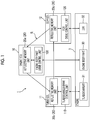
- Fig. 1 is a diagram showing the functional configuration of the engine control system according to the first embodiment.
- an engine control system 1 includes a plurality of control devices (engine ECU 10, turbo ECU 11, and EGR-ECU 12) which respectively have a plurality of engine units (engine body part 30, turbocharger 31, and EGR 32) constituting an engine 3 as a target to be controlled.
- the engine ECU 10 is a control device which controls the drive of an engine body part 30 in the engine 3.
- the engine ECU 10 performs control such that the operation state of the entire engine 3 is optimized in cooperation with the turbo ECU 11 and the EGR-ECU 12 according to an input command based on a driver's operation (depression of an accelerator pedal, or the like).
- a driver's operation depression of an accelerator pedal, or the like.
- the turbo ECU 11 is a control device which controls the drive of a turbocharger 31 among the engine units constituting the engine 3.
- the EGR-ECU 12 is a control device which controls the drive of the EGR 32 among the engine units constituting the engine 3.
- the engine ECU 10 includes an engine body part drive control unit 100 (drive control unit).
- the engine body part drive control unit 100 controls the drive of the engine body part 30 as an engine unit to be controlled according to memory information stored in a memory 200 (see Fig. 2 ) of a reflective memory unit 20a in the engine ECU 10.
- the turbo ECU 11 includes a turbocharger drive control unit 110 (drive control unit).
- the turbocharger drive control unit 110 controls the drive of the turbocharger 31 as an engine unit to be controlled according to memory information stored in a memory 200 (see Fig. 2 ) of a reflective memory unit 20b in the turbo ECU 11.
- the EGR-ECU 12 includes an EGR drive control unit 120 (drive control unit).
- the EGR drive control unit 120 controls the drive of the EGR 32 as an engine unit to be controlled according to memory information stored in a memory 200 (see Fig. 2 ) of a reflective memory unit 20c in the EGR-ECU 12.
- the reflective memory unit 20 (20a, 20b, 20c) provided in each of a plurality of control devices is a unit which manages memory information required when the control device (each of the drive control units) controls the drive of each engine unit constituting the engine 3.
- a plurality of reflective memory units 20 (20a, 20b, 20c) are connected to one another by a communication network R which is a ring network.
- Each reflective memory unit 20 is configured such that memory information stored therein flows in one direction through the communication network R wired in a ring shape.
- the reflective memory unit 20a in the engine ECU 10 outputs memory information stored therein toward the reflective memory unit 20b in the turbo ECU 11.
- the reflective memory unit 20b in the turbo ECU 11 outputs memory information stored therein toward the reflective memory unit 20c in the EGR-ECU 12.
- the reflective memory unit 20c in the EGR-ECU 12 outputs memory information stored therein toward the reflective memory unit 20a in the engine ECU 10.
- the communication network R is constituted of an optical fiber as a communication wiring. With this, it is possible to achieve reduction in weight of the entire engine control system 1, and to improve communication speed and reliability of communication.
- the reflective memory units 20 are not limited to the above-described aspect in other embodiments, and may be connected by a communication network other than a ring shape or may be connected by a communication wiring (general metal wiring) other than an optical fiber.
- a plurality of reflective memory units 20 output and update the memory information by way of the communication network R such that the respective pieces of memory information stored therein become identical.
- the function of the reflective memory unit 20 will be described in detail.
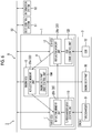
- Fig. 2 is a diagram showing the functional configuration of the reflective memory unit according to the first embodiment.
- the functional configuration of the reflective memory unit 20a in the engine ECU 10 is shown as an example, the functional configurations of the reflective memory units 20b and 20c in other control devices (turbo ECU 11 and EGR-ECU 12) are the same as the functional configuration shown in Fig. 2 .
- the reflective memory unit 20 includes the memory 200, a memory information output unit 201, and a memory information update unit 202.
- the memory 200 is a storage area where memory information required for controlling the drive of each engine unit constituting the engine 3 is stored.
- the configuration of the storage area of the memory 200 will be described below.
- the memory information output unit 201 outputs the memory information stored in the memory 200 of the reflective memory unit 20a to the reflective memory unit 20 (the reflective memory unit 20b in the turbo ECU 11) in another control device.
- the memory information update unit 202 writes the memory information received from the memory information output unit 201 of the reflective memory unit 20 (the reflective memory unit 20c in the EGR-ECU 12) in another control device into the memory 200 in the reflective memory unit 20a.
- the memory information output unit 201 and the memory information update unit 202 of each reflective memory unit 20 successively executes the above-described processing, whereby the memory information stored in the memory 200 of the reflective memory unit 20 becomes identical among the respective control devices (engine ECU 10, turbo ECU 11, and EGR-ECU 12) and sharing of the memory information is achieved.
- the reflective memory units 20 are connected by a ring network (communication network R), and the order in which the memory information flows is always constant. That is, the memory information output unit 201 according to this embodiment outputs the memory information to one specific control device specified in advance, and the memory information update unit 202 receives the memory information from the memory information output unit 201 from one specific control device specified in advance.
- a ring network communication network R
- the memory information output unit 201 of the reflective memory unit 20a is specified in advance to output the memory information toward the memory information update unit 202 of the reflective memory unit 20b.
- the memory information output unit 201 of the reflective memory unit 20b is specified in advance to output the memory information toward the memory information update unit 202 of the reflective memory unit 20c.
- the memory information output unit 201 of the reflective memory unit 20c is specified in advance to output the memory information toward the memory information update unit 202 of the reflective memory unit 20a.
- Fig. 3 is a diagram illustrating the storage area of the memory according to the first embodiment.
- the memory 200 in each of the reflective memory units 20a, 20b, and 20c has a plurality of types of storage areas divided in advance as shown in Fig. 3 .
- the storage area of the memory 200 is divided into an engine body part control storage area A01, a turbo control storage area A02, and an EGR control storage area A03.
- the memory information required for controlling the drive of the engine body part 30 ( Fig. 1 ) is stored.
- the engine body part drive control unit 100 ( Fig. 1 ) performs the control of the engine body part 30 with reference to the engine body part control storage area A01 in the memory 200 mounted in the reflective memory unit 20a ( Fig. 1 ).
- turbo control storage area A02 the memory information required for controlling the drive of the turbocharger 31 ( Fig. 1 ) is stored.
- the turbocharger drive control unit 110 ( Fig. 1 ) performs the control of the turbocharger 31 with reference to the turbo control storage area A02 in the memory 200 mounted in the reflective memory unit 20b ( Fig. 1 ).
- the memory information required for controlling the drive of the EGR 32 ( Fig. 1 ) is stored.
- the EGR drive control unit 120 ( Fig. 1 ) performs the control of the EGR 32 with reference to the EGR control storage area A03 in the memory 200 mounted in the reflective memory unit 20c ( Fig. 1 ).
- each of the drive control units refers to the storage area which is divided in advance in the storage area of the memory 200 in each control device and into which information relating to the drive of the engine unit as a target to be controlled of each drive control unit is written.
- Fig. 4 is a diagram showing a processing flow of the engine control system according to the first embodiment.
- the engine ECU 10 gives notification of an accelerator depression amount according to the driver's depression through an accelerator position sensor (not shown) (Step S01).
- the engine ECU 10 writes a control value (for example, a fuel injection amount command value) for the engine body part 30 according to the detected accelerator depression amount into the engine body part control storage area A01 divided in the memory 200 (the memory 200 of the reflective memory unit 20a) in the engine ECU 10.
- the engine ECU 10 writes a control value (for example, a supercharging pressure command value) for the turbocharger 31 according to the detected accelerator depression amount into the turbo control storage area A02 divided in the memory 200 in the engine ECU 10.
- the engine ECU 10 writes a control value (for example, an EGR amount command value) for the EGR 32 according to the detected accelerator depression amount into the EGR control storage area A03 divided in the memory 200 in the engine ECU 10.
- the engine ECU 10 updates the memory information by writing all command values corresponding to the respective engine units according to a driver's operation into respective predetermined areas of the memory 200 in the engine ECU 10 (Step S02).
- Step S02 if the memory information of the memory 200 mounted in the reflective memory unit 20a is updated, the memory information output unit 201 of the reflective memory unit 20a immediately outputs various kinds of updated memory information to the reflective memory unit 20b in the turbo ECU 11.
- the memory information update unit 202 of the reflective memory unit 20b updates the memory information by writing the received memory information into the memory 200 of the reflective memory unit 20b.
- the memory information output unit 201 of the reflective memory unit 20b immediately outputs various kinds of updated memory information to the reflective memory unit 20c in the EGR-ECU 12.
- the memory information update unit 202 of the reflective memory unit 20c updates the memory information by writing the received memory information into the memory 200 of the reflective memory unit 20c.
- Step S03 if the memory information (fuel injection amount command value, supercharging pressure command value, and EGR amount command value) of the memory 200 in the engine ECU 10 is newly updated, sharing processing of the memory information with other control devices is instantly performed (Step S03).
- the engine body part drive control unit 100 controls the engine body part 30 according to the memory information stored in the engine body part control storage area A01 in the memory 200 of the reflective memory unit 20a mounted in the engine ECU 10. With this, the engine body part drive control unit 100 controls a fuel injection amount in the engine body part 30 according to the fuel injection amount command value newly written into the engine body part control storage area A01 (Step S04).
- the turbocharger drive control unit 110 controls the turbocharger 31 according to the memory information stored in the turbo control storage area A02 in the memory 200 of the reflective memory unit 20b mounted in the turbo ECU 11. With this, the turbocharger drive control unit 110 controls a valve opening in the turbocharger 31 according to the supercharging pressure command value newly written into the turbo control storage area A02 (Step S05).
- the EGR drive control unit 120 controls the EGR 32 according to the memory information stored in the EGR control storage area A03 in the memory 200 of the reflective memory unit 20c mounted in the EGR-ECU 12. With this, the EGR drive control unit 120 controls a valve opening in the EGR 32 according to the EGR amount command value newly written into the EGR control storage area A03 (Step S06).
- Step S04 to Step S06 described above are actually executed simultaneously and in parallel by the respective control devices (the engine ECU 10, the turbo ECU 11, and the EGR-ECU 12).
- the engine control system 1 controls the drive of the engine 3 while repeatedly executing Step S01 to Step S06 described above.
- the engine control system 1 described above it is possible to significantly reduce processing loads of the respective control devices (the engine ECU 10, the turbo ECU 11, and the EGR-ECU 12).
- the control device needs to execute communication processing, such as transmission and reception of information required for cooperative control, in addition to control processing of the corresponding engine unit.
- each control device since each control device has the reflective memory unit 20 mounted therein, the control device does not need to perform communication processing. That is, since each control device has simply to perform control with reference to only the memory information written into the memory (memory 200) therein, it is possible to reduce a load of the control device, to accelerate processing, and to increase response characteristics to an input command.
- the independent communication network R among the control devices is newly provided, whereby it is possible to accelerate and stabilize communication among the control devices, and to achieve high accuracy and high reliability of cooperative control by a plurality of control devices.
- a plurality of reflective memory units 20 are connected through a ring network (communication network R), and the order in which the respective pieces of memory information flow is specified in one direction in advance.
- a ring network communication network R
- the respective reflective memory units 20 are configured such that the memory information flows in an order of the engine ECU 10, the turbo ECU 11, and the EGR-ECU 12.
- the invention is not limited to this aspect, and a configuration in which the memory information flow in a reverse direction (an order of the engine ECU 10, the EGR-ECU 12, and the turbo ECU 11) may be made.
- the control devices constituting the engine control system 1 are not limited only to the engine ECU 10, the turbo ECU 11, and the EGR-ECU 12. That is, an engine control system 1 according to other embodiments may further include other control devices which have engine units as a target to be controlled other than the engine body part 30, the turbocharger 31, and the EGR 32. In this case, it is assumed that others control devices have reflective memory units mounted therein, and are incorporated in a ring network (communication network R).
- Fig. 5 is a diagram illustrating the function of the engine control system according to the second embodiment.
- each of the drive control units controls the drive of the engine unit as a target to be controlled of each drive control unit based on various command values stored in the reflective memory unit 20 (memory 200) in each control device.
- Each of the drive control units shares various observation values corresponding to the respective command values through the reflective memory unit 20.
- Each drive control unit controls the drive of each engine unit to be controlled with reference to a storage area, into which information relating to the drive of engine unit not as a target to be controlled of each drive control unit is written, in the storage area of the memory 200 in each control device.
- the turbocharger drive control unit 110 performs valve control of the turbocharger 31 based on the supercharging pressure command value written into the turbo control storage area A02 ( Fig. 3 ) divided in the memory 200 of the reflective memory unit 20b.
- the turbocharger drive control unit 110 writes an intake air amount observation value measured in the turbocharger 31 into the turbo control storage area A02 divided in the memory 200 of the reflective memory unit 20b.
- the EGR drive control unit 120 performs valve control of the EGR 32 based on the EGR amount command value written into the EGR control storage area A03 ( Fig. 3 ) of the memory 200 of the reflective memory unit 20c.
- the EGR drive control unit 120 writes an EGR amount observation value measured in the EGR 32 into the EGR control storage area A03 divided in the memory 200 of the reflective memory unit 20c.
- each reflective memory unit 20 instantly executes the sharing processing (see Step S03 shown in Fig. 4 ) of the memory information.
- Step S03 shown in Fig. 4 the memory 200 mounted in each of the reflective memory units 20a, 20b, and 20c, not only various command values written by the engine ECU 10 but also various observation values (intake air value observation value and EGR amount observation value) observation in the respective engine units are shared.
- the turbocharger drive control unit 110 performs control based on the EGR amount observation value measured by the EGR 32 with reference to not only the intake air amount command value written into the turbo control storage area A02 but also the EGR control storage area A03 into which information relating to the drive of the EGR 32 not as a target to be controlled is written.
- the turbocharger drive control unit 110 can execute valve control based on the supercharging pressure command value stored in the turbo control storage area A02 and the EGR amount observation value stored in the EGR control storage area A03 such that a mechanical load is suppressed or an optimum intake air amount for maximizing energy efficiency is obtained.
- the EGR drive control unit 120 performs control based on the intake air amount observation amount measured by the turbocharger 31 with reference to not only the EGR amount command value written into the EGR control storage area A03 and the turbo control storage area A02 into which information relating to the drive of the turbocharger 31 not as a target to be controlled is written.
- the EGR drive control unit 120 can execute valve control based on the EGR amount command value stored in the EGR control storage area A03 and the intake air amount observation value stored in the turbo control storage area A02 such that an optimum EGR amount is obtained.
- the engine control system 1 of the second embodiment it is possible to execute optimum control as the whole of the engine 3 with reference to not only information relating to an engine unit as a target to be controlled but also information relating to the an engine unit not as a target to be controlled.
- turbocharger drive control unit 110 executes the valve control based on the supercharging pressure command value stored in the turbo control storage area A02 and the EGR amount observation value stored in the EGR control storage area A03
- the invention is not limited to this aspect.
- the turbocharger drive control unit 110 may perform the valve control based on a deviation between the EGR amount command value and the EGR amount observation value while referring to the EGR amount command value stored in the EGR control storage area A03. The same applies to the EGR drive control unit 120 described above.
- Fig. 6 is a diagram showing the functional configuration of the vehicle system according to the third embodiment.
- a vehicle system 5 includes the engine control system 1 according to the first embodiment (or the second embodiment), a bus 50, a body control system 51, and an information system 52.
- the engine control system 1 has a plurality of control devices (the engine ECU 10, the turbo ECU 11, and the EGR-ECU 12) which respectively control the respective engine units constituting the engine 3.
- the body control system 51 is one in-vehicle system mounted in a vehicle, and is an in-vehicle system which controls windows, doors, or the like of the vehicle.
- the information system 52 is one in-vehicle system mounted in the vehicle, and is an in-vehicle system which controls a car navigation device, audio instrument, or the like.
- the bus 50 constitutes a communication network B which allows communication among a plurality of control devices (the engine ECU 10, the turbo ECU 11, and the EGR-ECU 12) constituting the engine control system 1, the body control system 51, and the information system 52. That is, the vehicle system 5 according to this embodiment is constituted of the communication network B which is a bus network. In general, communication between the respective systems by way of the communication network B is performed, for example, using CAN communication.
- the vehicle system 5 is constructed by combining two different independent communication networks including the ring network (communication network R) which connect the respective reflective memory units 20 in the engine control system 1 and the bus network which allows CAN communication with other in-vehicle systems (body control system 51, the information system 52, and the like).
- the ring network communication network R
- the bus network which allows CAN communication with other in-vehicle systems (body control system 51, the information system 52, and the like).
- the bus network (communication network B) of the related art is applied in the communication network in which high-speed communication is not required, and a ring network (communication network R) is applied in the engine control system 1 in which high speed and high reliability are required. Therefore, it is possible to implement this configuration only by adding a minimum required network (communication network R) to an existing network configuration, and to minimize labor or costs concerning network design.
Landscapes
- Engineering & Computer Science (AREA)
- General Engineering & Computer Science (AREA)
- Mechanical Engineering (AREA)
- Chemical & Material Sciences (AREA)
- Combustion & Propulsion (AREA)
- Computer Hardware Design (AREA)
- Microelectronics & Electronic Packaging (AREA)
- Combined Controls Of Internal Combustion Engines (AREA)
- Exhaust-Gas Circulating Devices (AREA)
- Output Control And Ontrol Of Special Type Engine (AREA)
- Supercharger (AREA)
Abstract
Description
- The present invention relates to an engine control system, a vehicle system, and an engine control method.
- This application claims the benefit of priority based on Japanese Patent Application No.
2014-206298, filed October 7, 2014 - In recent years, there is a case where, in order to control devices, such as an engine, a turbocharger, and an exhaust gas recirculation (EGR), an engine control system divided into an engine control unit (ECU) configured to control an engine body part and an ECU configured to control the turbocharger, the EGR, or the like is mounted.
- Since the ECUs which control the above-described devices constituting the engine need to control the engine body part, the turbocharger, the EGR, and the like in cooperation with one another, the amount of communication between the ECUs increases, and calculation loads of the ECUs tend to increase.
- If communication delay occurs in a network of the ECUs, it is supposed that control of the engine becomes unstable. For this reason, a communication network which includes a network relay device or a database distribution node so as to prevent the occurrence of communication delay has been suggested (for example, see
PTL 1 and PTL 2). -
- [PTL 1] Japanese Unexamined Patent Application Publication No.
2007-166302 - [PTL 2] Japanese Unexamined Patent Application Publication No.
2007-300331 - However, if the communication network is about to be constructed so as to prevent the occurrence of communication delay between the ECUs, the form of the communication network becomes complicated, and labor and cost required for designing the communication network increase.
- An object of the invention is to provide an engine control system, a vehicle system, and an engine control method capable of reducing a calculation load of each ECU while suppressing communication delay between ECUs.
- According to a first aspect of the invention, an engine control system includes a plurality of control devices which respectively have a plurality of engine units constituting an engine as a target to be controlled. Each of the plurality of control devices includes a drive control unit which controls the drive of the engine unit to be controlled according to memory information stored in a memory of the control device, a memory information output unit which outputs memory information stored in the memory of the control device to other control devices, and a memory information update unit which writes memory information received from the memory information output units of other control devices into the memory of the control device.
- According to a second aspect of the invention, the memory information output unit outputs the memory information to one specific control device specified in advance, and the memory information update unit receives the memory information from the memory information output unit of the one specific control device specified in advance.
- According to a third aspect of the invention, the drive control unit refers to a storage area which is a storage area divided in advance in a storage area of the memory and into which information relating to the drive of the engine unit to be controlled is written.
- According to a fourth aspect of the invention, the drive control unit further refers to a storage area which is a storage area divided in advance in the storage area of the memory and into which information relating to the drive of the engine unit not to be controlled is written.
- According to a fifth aspect of the invention, a vehicle system includes the above-described engine control system, and an in-vehicle system which is mounted in a vehicle. The engine control system and the in-vehicle system are connected through a communication network independent from a communication network which connects the memory information output units and the memory information update units of the plurality of control devices.
- According to a sixth aspect of the invention, there is provided an engine control method which controls an engine using a plurality of control devices respectively having a plurality of engine units constituting the engine as a target to be controlled. The engine control method includes a step of controlling the drive of the engine unit to be controlled according to memory information stored in a memory of each of the plurality of control devices, a step of enabling a memory information output unit to output memory information stored in the memory of the control device to other control devices, and a step of writing memory information received from the memory information output units of other control devices into the memory of the control device. Advantageous Effects of Invention
- According to the storage area, the vehicle system, and the engine control method described above, it is possible to reduce a calculation load of each ECU while suppressing communication delay between ECUs.
-
-
Fig. 1 is a diagram showing the functional configuration of an engine control system according to a first embodiment. -
Fig. 2 is a diagram showing the functional configuration of a reflective memory unit according to the first embodiment. -
Fig. 3 is a diagram illustrating a storage area of a memory according to the first embodiment. -
Fig. 4 is a diagram showing a processing flow of the engine control system according to the first embodiment. -
Fig. 5 is a diagram illustrating a function of an engine control system according to a second embodiment. -
Fig. 6 is a diagram showing the functional configuration of a vehicle system according to a third embodiment. - Hereinafter, an engine control system according to a first embodiment will be described in detail referring to
Figs. 1 to 4 . -
Fig. 1 is a diagram showing the functional configuration of the engine control system according to the first embodiment. - As shown in
Fig. 1 , anengine control system 1 includes a plurality of control devices (engine ECU 10, turbo ECU 11, and EGR-ECU 12) which respectively have a plurality of engine units (engine body part 30,turbocharger 31, and EGR 32) constituting anengine 3 as a target to be controlled. - The engine ECU 10 is a control device which controls the drive of an
engine body part 30 in theengine 3. The engine ECU 10 performs control such that the operation state of theentire engine 3 is optimized in cooperation with the turbo ECU 11 and the EGR-ECU 12 according to an input command based on a driver's operation (depression of an accelerator pedal, or the like). The cooperative operation of theturbo ECU 11 and the EGR-ECU 12 will be described below. - The turbo ECU 11 is a control device which controls the drive of a
turbocharger 31 among the engine units constituting theengine 3. - The EGR-ECU 12 is a control device which controls the drive of the EGR 32 among the engine units constituting the
engine 3. - The engine ECU 10 includes an engine body part drive control unit 100 (drive control unit). The engine body part
drive control unit 100 controls the drive of theengine body part 30 as an engine unit to be controlled according to memory information stored in a memory 200 (seeFig. 2 ) of areflective memory unit 20a in theengine ECU 10. - The turbo ECU 11 includes a turbocharger drive control unit 110 (drive control unit). The turbocharger
drive control unit 110 controls the drive of theturbocharger 31 as an engine unit to be controlled according to memory information stored in a memory 200 (seeFig. 2 ) of areflective memory unit 20b in theturbo ECU 11. - Similarly, the EGR-ECU 12 includes an EGR drive control unit 120 (drive control unit). The EGR
drive control unit 120 controls the drive of the EGR 32 as an engine unit to be controlled according to memory information stored in a memory 200 (seeFig. 2 ) of areflective memory unit 20c in the EGR-ECU 12. - The reflective memory unit 20 (20a, 20b, 20c) provided in each of a plurality of control devices (engine ECU 10,
turbo ECU 11, and EGR-ECU 12) is a unit which manages memory information required when the control device (each of the drive control units) controls the drive of each engine unit constituting theengine 3. - As shown in
Fig. 1 , a plurality of reflective memory units 20 (20a, 20b, 20c) are connected to one another by a communication network R which is a ring network. Eachreflective memory unit 20 is configured such that memory information stored therein flows in one direction through the communication network R wired in a ring shape. - Specifically, the
reflective memory unit 20a in theengine ECU 10 outputs memory information stored therein toward thereflective memory unit 20b in theturbo ECU 11. Thereflective memory unit 20b in theturbo ECU 11 outputs memory information stored therein toward thereflective memory unit 20c in the EGR-ECU 12. Similarly, thereflective memory unit 20c in the EGR-ECU 12 outputs memory information stored therein toward thereflective memory unit 20a in theengine ECU 10. - In this embodiment, the communication network R is constituted of an optical fiber as a communication wiring. With this, it is possible to achieve reduction in weight of the entire
engine control system 1, and to improve communication speed and reliability of communication. - The
reflective memory units 20 are not limited to the above-described aspect in other embodiments, and may be connected by a communication network other than a ring shape or may be connected by a communication wiring (general metal wiring) other than an optical fiber. - A plurality of
reflective memory units 20 output and update the memory information by way of the communication network R such that the respective pieces of memory information stored therein become identical. Hereinafter, the function of thereflective memory unit 20 will be described in detail. -
Fig. 2 is a diagram showing the functional configuration of the reflective memory unit according to the first embodiment. - In regard to the
reflective memory unit 20 shown inFig. 2 , while the functional configuration of thereflective memory unit 20a in theengine ECU 10 is shown as an example, the functional configurations of thereflective memory units turbo ECU 11 and EGR-ECU 12) are the same as the functional configuration shown inFig. 2 . - As shown in
Fig. 2 , thereflective memory unit 20 includes thememory 200, a memoryinformation output unit 201, and a memoryinformation update unit 202. - The
memory 200 is a storage area where memory information required for controlling the drive of each engine unit constituting theengine 3 is stored. The configuration of the storage area of thememory 200 will be described below. - The memory
information output unit 201 outputs the memory information stored in thememory 200 of thereflective memory unit 20a to the reflective memory unit 20 (thereflective memory unit 20b in the turbo ECU 11) in another control device. - The memory
information update unit 202 writes the memory information received from the memoryinformation output unit 201 of the reflective memory unit 20 (thereflective memory unit 20c in the EGR-ECU 12) in another control device into thememory 200 in thereflective memory unit 20a. - The memory
information output unit 201 and the memoryinformation update unit 202 of eachreflective memory unit 20 successively executes the above-described processing, whereby the memory information stored in thememory 200 of thereflective memory unit 20 becomes identical among the respective control devices (engine ECU 10,turbo ECU 11, and EGR-ECU 12) and sharing of the memory information is achieved. - In this embodiment, the
reflective memory units 20 are connected by a ring network (communication network R), and the order in which the memory information flows is always constant. That is, the memoryinformation output unit 201 according to this embodiment outputs the memory information to one specific control device specified in advance, and the memoryinformation update unit 202 receives the memory information from the memoryinformation output unit 201 from one specific control device specified in advance. - For example, the memory
information output unit 201 of thereflective memory unit 20a is specified in advance to output the memory information toward the memoryinformation update unit 202 of thereflective memory unit 20b. The memoryinformation output unit 201 of thereflective memory unit 20b is specified in advance to output the memory information toward the memoryinformation update unit 202 of thereflective memory unit 20c. The memoryinformation output unit 201 of thereflective memory unit 20c is specified in advance to output the memory information toward the memoryinformation update unit 202 of thereflective memory unit 20a. -
Fig. 3 is a diagram illustrating the storage area of the memory according to the first embodiment. - The
memory 200 in each of thereflective memory units Fig. 3 . Specifically, the storage area of thememory 200 is divided into an engine body part control storage area A01, a turbo control storage area A02, and an EGR control storage area A03. - In the engine body part control storage area A01, the memory information required for controlling the drive of the engine body part 30 (
Fig. 1 ) is stored. The engine body part drive control unit 100 (Fig. 1 ) performs the control of theengine body part 30 with reference to the engine body part control storage area A01 in thememory 200 mounted in thereflective memory unit 20a (Fig. 1 ). - In the turbo control storage area A02, the memory information required for controlling the drive of the turbocharger 31 (
Fig. 1 ) is stored. The turbocharger drive control unit 110 (Fig. 1 ) performs the control of theturbocharger 31 with reference to the turbo control storage area A02 in thememory 200 mounted in thereflective memory unit 20b (Fig. 1 ). - Similarly, in the EGR control storage area A03, the memory information required for controlling the drive of the EGR 32 (
Fig. 1 ) is stored. The EGR drive control unit 120 (Fig. 1 ) performs the control of theEGR 32 with reference to the EGR control storage area A03 in thememory 200 mounted in thereflective memory unit 20c (Fig. 1 ). - As described above, each of the drive control units (the engine body part
drive control unit 100, the turbochargerdrive control unit 110, and the EGR drive control unit 120) refers to the storage area which is divided in advance in the storage area of thememory 200 in each control device and into which information relating to the drive of the engine unit as a target to be controlled of each drive control unit is written. -
Fig. 4 is a diagram showing a processing flow of the engine control system according to the first embodiment. - Hereinafter, an operation example of the
engine control system 1 will be described referring toFigs. 1 ,2 ,3 , and4 . - For example, in a case where an accelerator pedal is depressed by a driver, or the like, the
engine ECU 10 gives notification of an accelerator depression amount according to the driver's depression through an accelerator position sensor (not shown) (Step S01). - The
engine ECU 10 writes a control value (for example, a fuel injection amount command value) for theengine body part 30 according to the detected accelerator depression amount into the engine body part control storage area A01 divided in the memory 200 (thememory 200 of thereflective memory unit 20a) in theengine ECU 10. Similarly, theengine ECU 10 writes a control value (for example, a supercharging pressure command value) for theturbocharger 31 according to the detected accelerator depression amount into the turbo control storage area A02 divided in thememory 200 in theengine ECU 10. In addition, theengine ECU 10 writes a control value (for example, an EGR amount command value) for theEGR 32 according to the detected accelerator depression amount into the EGR control storage area A03 divided in thememory 200 in theengine ECU 10. - In this way, the
engine ECU 10 updates the memory information by writing all command values corresponding to the respective engine units according to a driver's operation into respective predetermined areas of thememory 200 in the engine ECU 10 (Step S02). - Through Step S02, if the memory information of the
memory 200 mounted in thereflective memory unit 20a is updated, the memoryinformation output unit 201 of thereflective memory unit 20a immediately outputs various kinds of updated memory information to thereflective memory unit 20b in theturbo ECU 11. The memoryinformation update unit 202 of thereflective memory unit 20b updates the memory information by writing the received memory information into thememory 200 of thereflective memory unit 20b. In addition, the memoryinformation output unit 201 of thereflective memory unit 20b immediately outputs various kinds of updated memory information to thereflective memory unit 20c in the EGR-ECU 12. The memoryinformation update unit 202 of thereflective memory unit 20c updates the memory information by writing the received memory information into thememory 200 of thereflective memory unit 20c. - With this procedure, if the memory information (fuel injection amount command value, supercharging pressure command value, and EGR amount command value) of the
memory 200 in theengine ECU 10 is newly updated, sharing processing of the memory information with other control devices is instantly performed (Step S03). - The engine body part
drive control unit 100 controls theengine body part 30 according to the memory information stored in the engine body part control storage area A01 in thememory 200 of thereflective memory unit 20a mounted in theengine ECU 10. With this, the engine body partdrive control unit 100 controls a fuel injection amount in theengine body part 30 according to the fuel injection amount command value newly written into the engine body part control storage area A01 (Step S04). - The turbocharger
drive control unit 110 controls theturbocharger 31 according to the memory information stored in the turbo control storage area A02 in thememory 200 of thereflective memory unit 20b mounted in theturbo ECU 11. With this, the turbochargerdrive control unit 110 controls a valve opening in theturbocharger 31 according to the supercharging pressure command value newly written into the turbo control storage area A02 (Step S05). - The EGR
drive control unit 120 controls theEGR 32 according to the memory information stored in the EGR control storage area A03 in thememory 200 of thereflective memory unit 20c mounted in the EGR-ECU 12. With this, the EGRdrive control unit 120 controls a valve opening in theEGR 32 according to the EGR amount command value newly written into the EGR control storage area A03 (Step S06). - The respective processing of Step S04 to Step S06 described above are actually executed simultaneously and in parallel by the respective control devices (the
engine ECU 10, theturbo ECU 11, and the EGR-ECU 12). - The
engine control system 1 controls the drive of theengine 3 while repeatedly executing Step S01 to Step S06 described above. - According to the
engine control system 1 described above, it is possible to significantly reduce processing loads of the respective control devices (theengine ECU 10, theturbo ECU 11, and the EGR-ECU 12). For example, in a case where each control device is connected through a bus communication network based on controller area network (CAN) communication in the related art, the control device needs to execute communication processing, such as transmission and reception of information required for cooperative control, in addition to control processing of the corresponding engine unit. - In contrast, in the
engine control system 1 according to this embodiment, since each control device has thereflective memory unit 20 mounted therein, the control device does not need to perform communication processing. That is, since each control device has simply to perform control with reference to only the memory information written into the memory (memory 200) therein, it is possible to reduce a load of the control device, to accelerate processing, and to increase response characteristics to an input command. - The independent communication network R among the control devices is newly provided, whereby it is possible to accelerate and stabilize communication among the control devices, and to achieve high accuracy and high reliability of cooperative control by a plurality of control devices.
- In this embodiment, a plurality of
reflective memory units 20 are connected through a ring network (communication network R), and the order in which the respective pieces of memory information flow is specified in one direction in advance. With this, it is possible to simplify an algorithm (that is, processing executed by the memoryinformation output unit 201 and the memory information update unit 202) required for the memory information, and to implement a high-speed and stable communication form. Therefore, it is possible to suppress offset of control of the control device due to communication delay, and to implement higher-accuracy cooperative control. - Although the
engine control system 1 according to the first embodiment has been described above in detail, a specific aspect of theengine control system 1 is not limited to that described above, and various design changes or the like may be added without departing from the spirit of the invention. - For example, in this embodiment, it has been described that the respective
reflective memory units 20 are configured such that the memory information flows in an order of theengine ECU 10, theturbo ECU 11, and the EGR-ECU 12. However, in other embodiments, the invention is not limited to this aspect, and a configuration in which the memory information flow in a reverse direction (an order of theengine ECU 10, the EGR-ECU 12, and the turbo ECU 11) may be made. - The control devices constituting the
engine control system 1 are not limited only to theengine ECU 10, theturbo ECU 11, and the EGR-ECU 12. That is, anengine control system 1 according to other embodiments may further include other control devices which have engine units as a target to be controlled other than theengine body part 30, theturbocharger 31, and theEGR 32. In this case, it is assumed that others control devices have reflective memory units mounted therein, and are incorporated in a ring network (communication network R). - Next, an engine control system according to a second embodiment will be described in detail referring to
Fig. 5 . -
Fig. 5 is a diagram illustrating the function of the engine control system according to the second embodiment. - As in the first embodiment, each of the drive control units (an engine body part
drive control unit 100, a turbochargerdrive control unit 110, and an EGR drive control unit 120) according to this embodiment controls the drive of the engine unit as a target to be controlled of each drive control unit based on various command values stored in the reflective memory unit 20 (memory 200) in each control device. - Each of the drive control units according to this embodiment shares various observation values corresponding to the respective command values through the
reflective memory unit 20. Each drive control unit controls the drive of each engine unit to be controlled with reference to a storage area, into which information relating to the drive of engine unit not as a target to be controlled of each drive control unit is written, in the storage area of thememory 200 in each control device. - Specifically, for example, as shown in
Fig. 5 , the turbochargerdrive control unit 110 performs valve control of theturbocharger 31 based on the supercharging pressure command value written into the turbo control storage area A02 (Fig. 3 ) divided in thememory 200 of thereflective memory unit 20b. The turbochargerdrive control unit 110 writes an intake air amount observation value measured in theturbocharger 31 into the turbo control storage area A02 divided in thememory 200 of thereflective memory unit 20b. - Similarly, as shown in
Fig. 5 , the EGRdrive control unit 120 performs valve control of theEGR 32 based on the EGR amount command value written into the EGR control storage area A03 (Fig. 3 ) of thememory 200 of thereflective memory unit 20c. The EGRdrive control unit 120 writes an EGR amount observation value measured in theEGR 32 into the EGR control storage area A03 divided in thememory 200 of thereflective memory unit 20c. - If the intake amount observation value is written by the turbocharger
drive control unit 110 or the EGR amount observation value is written the EGRdrive control unit 120 as described above, eachreflective memory unit 20 instantly executes the sharing processing (see Step S03 shown inFig. 4 ) of the memory information. With this, in thememory 200 mounted in each of thereflective memory units engine ECU 10 but also various observation values (intake air value observation value and EGR amount observation value) observation in the respective engine units are shared. - The turbocharger
drive control unit 110 according to this embodiment performs control based on the EGR amount observation value measured by theEGR 32 with reference to not only the intake air amount command value written into the turbo control storage area A02 but also the EGR control storage area A03 into which information relating to the drive of theEGR 32 not as a target to be controlled is written. - In this way, the turbocharger
drive control unit 110 can execute valve control based on the supercharging pressure command value stored in the turbo control storage area A02 and the EGR amount observation value stored in the EGR control storage area A03 such that a mechanical load is suppressed or an optimum intake air amount for maximizing energy efficiency is obtained. - Similarly, the EGR
drive control unit 120 according to this embodiment performs control based on the intake air amount observation amount measured by theturbocharger 31 with reference to not only the EGR amount command value written into the EGR control storage area A03 and the turbo control storage area A02 into which information relating to the drive of theturbocharger 31 not as a target to be controlled is written. - In this way, the EGR
drive control unit 120 can execute valve control based on the EGR amount command value stored in the EGR control storage area A03 and the intake air amount observation value stored in the turbo control storage area A02 such that an optimum EGR amount is obtained. - As described above, according to the
engine control system 1 of the second embodiment, it is possible to execute optimum control as the whole of theengine 3 with reference to not only information relating to an engine unit as a target to be controlled but also information relating to the an engine unit not as a target to be controlled. - In the above-described example, although the turbocharger
drive control unit 110 executes the valve control based on the supercharging pressure command value stored in the turbo control storage area A02 and the EGR amount observation value stored in the EGR control storage area A03, in other embodiments, the invention is not limited to this aspect. For example, the turbochargerdrive control unit 110 may perform the valve control based on a deviation between the EGR amount command value and the EGR amount observation value while referring to the EGR amount command value stored in the EGR control storage area A03. The same applies to the EGRdrive control unit 120 described above. - Next, a vehicle system according to a third embodiment will be described in detail referring to
Fig. 6 . -
Fig. 6 is a diagram showing the functional configuration of the vehicle system according to the third embodiment. - As shown in
Fig. 6 , a vehicle system 5 includes theengine control system 1 according to the first embodiment (or the second embodiment), abus 50, abody control system 51, and aninformation system 52. - As described above, the
engine control system 1 has a plurality of control devices (theengine ECU 10, theturbo ECU 11, and the EGR-ECU 12) which respectively control the respective engine units constituting theengine 3. - The
body control system 51 is one in-vehicle system mounted in a vehicle, and is an in-vehicle system which controls windows, doors, or the like of the vehicle. - Similarly, the
information system 52 is one in-vehicle system mounted in the vehicle, and is an in-vehicle system which controls a car navigation device, audio instrument, or the like. - The
bus 50 constitutes a communication network B which allows communication among a plurality of control devices (theengine ECU 10, theturbo ECU 11, and the EGR-ECU 12) constituting theengine control system 1, thebody control system 51, and theinformation system 52. That is, the vehicle system 5 according to this embodiment is constituted of the communication network B which is a bus network. In general, communication between the respective systems by way of the communication network B is performed, for example, using CAN communication. - As described above, the vehicle system 5 according to this embodiment is constructed by combining two different independent communication networks including the ring network (communication network R) which connect the respective
reflective memory units 20 in theengine control system 1 and the bus network which allows CAN communication with other in-vehicle systems (body control system 51, theinformation system 52, and the like). - In this way, in an engine control system which requires high-speed processing, with the use of an optical fiber, it is possible to perform communication at higher speed than the communication wiring of the related art. In addition, in a case where an optical fiber is used, it is possible to provide resistance against noise expected to be caused by communication or vibration in the engine, and to increase the reliability of the engine control system.
- The bus network (communication network B) of the related art is applied in the communication network in which high-speed communication is not required, and a ring network (communication network R) is applied in the
engine control system 1 in which high speed and high reliability are required. Therefore, it is possible to implement this configuration only by adding a minimum required network (communication network R) to an existing network configuration, and to minimize labor or costs concerning network design. - Although several embodiments of the invention have been described above, these embodiments are only examples and are not intended to limit the scope of the invention. These embodiments may be carried out in other various forms, and may include various omissions, replacements, or modifications without departing from the spirit of the invention. These embodiments and modifications are included in the scope or spirit of the invention, and similarly, are included in the inventions described in the appended claims and equivalents thereof.
- According to the respective embodiments described above, it is possible to reduce a calculation load of each ECU while suppressing communication delay between the ECUs.
-
- 1:
- engine control system
- 10:
- engine ECU (control device)
- 100:
- engine body part drive control unit(drive control unit)
- 11:
- turbo ECU (control device)
- 110:
- turbocharger drive control unit(drive control unit)
- 12:
- EGR-ECU (control device)
- 120:
- EGR drive control unit (drive control unit)
- 20, 20a, 20b, 20c:
- reflective memory unit
- 200:
- memory
- 201:
- memory information output unit
- 202:
- memory information update unit
- 3:
- engine
- 30:
- engine body part (engine unit)
- 31:
- turbocharger (engine unit)
- 32:
- EGR (engine unit)
- 5:
- vehicle system
- 50:
- bus
- 51:
- body control system (in-vehicle system)
- 52:
- information system (in-vehicle system)
- A01:
- engine body part control storage area
- A02:
- turbo control storage area
- A03:
- EGR control storage area
- B:
- communication network (bus network)
- R:
- communication network (ring network)
Claims (6)
- An engine control system comprising:a plurality of control devices which respectively control a plurality of engine units constituting an engine,wherein each of the plurality of control devices includesa drive control unit which controls the drive of the engine unit to be controlled according to memory information stored in a memory of the control device,a memory information output unit which outputs memory information stored in the memory of the control device to other control devices, anda memory information update unit which writes memory information received from the memory information output units of other control devices into the memory of the control device.
- The engine control system according to claim 1,
wherein the memory information output unit outputs the memory information to one specific control device specified in advance, and
the memory information update unit receives the memory information from the memory information output unit of the one specific control device specified in advance. - The engine control system according to claim 1 or 2,
wherein the drive control unit refers to a storage area which is a storage area divided in advance in a storage area of the memory and into which information relating to the drive of the engine unit to be controlled is written. - The engine control system according to claim 3,
wherein the drive control unit further refers to a storage area which is a storage area divided in advance in the storage area of the memory and into which information relating to the drive of the engine unit not to be controlled is written. - A vehicle system comprising:the engine control system according to any one of claims 1 to 4; andan in-vehicle system which is mounted in a vehicle,wherein the engine control system and the in-vehicle system are connected through a communication network independent from a communication network which connects the memory information output units and the memory information update units of the plurality of control devices.
- An engine control method which controls an engine using a plurality of control devices configured to respectively control a plurality of engine units constituting the engine, the engine control method comprising:a step of controlling the drive of the engine unit to be controlled according to memory information stored in a memory of each of the plurality of control devices;a step of enabling a memory information output unit to output memory information stored in the memory of the control device to other control devices; anda step of writing memory information received from the memory information output units of other control devices into the memory of the control device.
Applications Claiming Priority (2)
| Application Number | Priority Date | Filing Date | Title |
|---|---|---|---|
| JP2014206298A JP6057968B2 (en) | 2014-10-07 | 2014-10-07 | ENGINE CONTROL SYSTEM, VEHICLE SYSTEM, AND ENGINE CONTROL METHOD |
| PCT/JP2015/053356 WO2016056255A1 (en) | 2014-10-07 | 2015-02-06 | Engine control system, vehicle system, and engine control method |
Publications (3)
| Publication Number | Publication Date |
|---|---|
| EP3190284A1 true EP3190284A1 (en) | 2017-07-12 |
| EP3190284A4 EP3190284A4 (en) | 2017-09-13 |
| EP3190284B1 EP3190284B1 (en) | 2019-05-01 |
Family
ID=55652887
Family Applications (1)
| Application Number | Title | Priority Date | Filing Date |
|---|---|---|---|
| EP15849093.8A Active EP3190284B1 (en) | 2014-10-07 | 2015-02-06 | Engine control system, vehicle system, and engine control method |
Country Status (5)
| Country | Link |
|---|---|
| US (1) | US10683824B2 (en) |
| EP (1) | EP3190284B1 (en) |
| JP (1) | JP6057968B2 (en) |
| CN (1) | CN107110054B (en) |
| WO (1) | WO2016056255A1 (en) |
Family Cites Families (20)
| Publication number | Priority date | Publication date | Assignee | Title |
|---|---|---|---|---|
| US4791569A (en) * | 1985-03-18 | 1988-12-13 | Honda Giken Kogyo Kabushiki Kaisha | Electronic control system for internal combustion engines |
| DE4124987A1 (en) * | 1991-07-27 | 1993-01-28 | Bosch Gmbh Robert | SYSTEM FOR CONTROLLING SAFETY-RELEVANT SYSTEMS |
| SE503397C2 (en) * | 1994-09-11 | 1996-06-03 | Mecel Ab | Arrangement and method of a control system for an internal combustion engine comprising a distributed computer network |
| JP2002543327A (en) | 1999-04-21 | 2002-12-17 | シーメンス アクチエンゲゼルシヤフト | Control device for operating drive of internal combustion engine |
| JP4427860B2 (en) | 2000-03-24 | 2010-03-10 | 株式会社デンソー | VEHICLE CONTROL DEVICE AND RECORDING MEDIUM |
| US7315388B2 (en) * | 2001-01-24 | 2008-01-01 | Canon Kabushiki Kaisha | Image input/output control apparatus, image processing apparatus, image processing method, data communication apparatus, and data communication method |
| JP2002334023A (en) * | 2001-05-11 | 2002-11-22 | Denso Corp | Electronic control unit |
| JP2003058285A (en) * | 2001-08-10 | 2003-02-28 | Fujitsu Ten Ltd | Control system |
| JP4311067B2 (en) * | 2003-04-02 | 2009-08-12 | 株式会社デンソー | Data rewriting method and electronic control device |
| JP4415912B2 (en) | 2004-10-06 | 2010-02-17 | 株式会社デンソー | Engine control system |
| JP2007166302A (en) | 2005-12-14 | 2007-06-28 | Denso Corp | In-vehicle network relay device |
| JP5028852B2 (en) | 2006-04-25 | 2012-09-19 | 株式会社デンソー | Vehicle communication system |
| JP2007300331A (en) | 2006-04-28 | 2007-11-15 | Auto Network Gijutsu Kenkyusho:Kk | In-vehicle database system |
| JP4899848B2 (en) * | 2006-12-13 | 2012-03-21 | 株式会社デンソー | In-vehicle system |
| JP4859803B2 (en) | 2007-10-01 | 2012-01-25 | 日立オートモティブシステムズ株式会社 | Electric actuator control device |
| JP2009286295A (en) * | 2008-05-30 | 2009-12-10 | Hitachi Ltd | On-vehicle information-collecting system and data collecting method in on-vehicle information-collecting device |
| EP2430299B1 (en) * | 2009-05-13 | 2013-05-01 | Wärtsilä Finland Oy | Engine fuel supply control |
| JP5958374B2 (en) * | 2013-02-12 | 2016-07-27 | 株式会社デンソー | Vehicle control data storage device |
| CN203293918U (en) | 2013-06-26 | 2013-11-20 | 惠州市德赛西威汽车电子有限公司 | Meter system of commercial vehicle |
| CN103488565B (en) | 2013-09-13 | 2016-01-20 | 北京航空航天大学 | A kind of distributed real-time testing system test data collection method |
-
2014
- 2014-10-07 JP JP2014206298A patent/JP6057968B2/en not_active Expired - Fee Related
-
2015
- 2015-02-06 US US15/516,592 patent/US10683824B2/en not_active Expired - Fee Related
- 2015-02-06 CN CN201580053757.XA patent/CN107110054B/en not_active Expired - Fee Related
- 2015-02-06 WO PCT/JP2015/053356 patent/WO2016056255A1/en not_active Ceased
- 2015-02-06 EP EP15849093.8A patent/EP3190284B1/en active Active
Also Published As
| Publication number | Publication date |
|---|---|
| EP3190284A4 (en) | 2017-09-13 |
| US20180202381A1 (en) | 2018-07-19 |
| CN107110054A (en) | 2017-08-29 |
| EP3190284B1 (en) | 2019-05-01 |
| WO2016056255A1 (en) | 2016-04-14 |
| JP6057968B2 (en) | 2017-01-11 |
| JP2016075223A (en) | 2016-05-12 |
| US10683824B2 (en) | 2020-06-16 |
| CN107110054B (en) | 2020-11-06 |
Similar Documents
| Publication | Publication Date | Title |
|---|---|---|
| US8566008B2 (en) | Control device for internal combustion engine | |
| US20110225260A1 (en) | Vehicle Connectivity Systems, Methods and Applications | |
| CN112543153A (en) | Message forwarding method, device, system, equipment and storage medium | |
| US20110035124A1 (en) | Method of operating an automatic transmission as well as controller | |
| US20120185876A1 (en) | Control device, control method, and computer readable medium | |
| US11803364B2 (en) | Server, software updating device, vehicle, software updating system, control method, and non-transitory storage medium | |
| US11831718B2 (en) | In-vehicle equipment controller and vehicle control system | |
| US7319923B2 (en) | Method and device for controlling operational sequences in a vehicle | |
| EP1703391A2 (en) | Vehicle control software and vehicle control apparatus | |
| JP4862792B2 (en) | Control device for drive unit | |
| US10683824B2 (en) | Engine control system, vehicle system, and engine control method | |
| AU2015271955A1 (en) | Vehicle computer system with data backup | |
| JP2022154943A (en) | Vehicle controlling system, vehicle, and control method | |
| JP4835937B2 (en) | Traveling vehicle system | |
| US11956096B2 (en) | Automotive, naval, and aircraft bus-emulator | |
| JP5790514B2 (en) | Electronic equipment | |
| JP5359839B2 (en) | Control device for internal combustion engine | |
| CN118144786A (en) | Vehicle acceleration continuity control method and device, electronic controller and medium | |
| KR20230060479A (en) | Method and apparatus for controlling power of hybrid vehicle considering transient characteristics | |
| US20240411546A1 (en) | Vehicle control apparatus | |
| CN117742807A (en) | Process starting method, process management method and management device | |
| EP3434886B1 (en) | After treatment system thermal management method | |
| US20240281241A1 (en) | Write control device, update control device, electronic control system, software update control method, and storage medium storing software update control program | |
| US20250340216A1 (en) | Safety rule generation device, navigation system, safety rule generation method, navigation method, and program | |
| US20250238223A1 (en) | Vehicle software management apparatus and vehicle software management system |
Legal Events
| Date | Code | Title | Description |
|---|---|---|---|
| STAA | Information on the status of an ep patent application or granted ep patent |
Free format text: STATUS: THE INTERNATIONAL PUBLICATION HAS BEEN MADE |
|
| PUAI | Public reference made under article 153(3) epc to a published international application that has entered the european phase |
Free format text: ORIGINAL CODE: 0009012 |
|
| STAA | Information on the status of an ep patent application or granted ep patent |
Free format text: STATUS: REQUEST FOR EXAMINATION WAS MADE |
|
| 17P | Request for examination filed |
Effective date: 20170403 |
|
| AK | Designated contracting states |
Kind code of ref document: A1 Designated state(s): AL AT BE BG CH CY CZ DE DK EE ES FI FR GB GR HR HU IE IS IT LI LT LU LV MC MK MT NL NO PL PT RO RS SE SI SK SM TR |
|
| AX | Request for extension of the european patent |
Extension state: BA ME |
|
| A4 | Supplementary search report drawn up and despatched |
Effective date: 20170814 |
|
| RIC1 | Information provided on ipc code assigned before grant |
Ipc: F02D 45/00 20060101AFI20170808BHEP Ipc: F02D 41/26 20060101ALI20170808BHEP Ipc: B60R 16/02 20060101ALI20170808BHEP Ipc: F02D 41/24 20060101ALI20170808BHEP Ipc: F02D 41/00 20060101ALN20170808BHEP |
|
| DAX | Request for extension of the european patent (deleted) | ||
| STAA | Information on the status of an ep patent application or granted ep patent |
Free format text: STATUS: EXAMINATION IS IN PROGRESS |
|
| 17Q | First examination report despatched |
Effective date: 20180615 |
|
| GRAP | Despatch of communication of intention to grant a patent |
Free format text: ORIGINAL CODE: EPIDOSNIGR1 |
|
| STAA | Information on the status of an ep patent application or granted ep patent |
Free format text: STATUS: GRANT OF PATENT IS INTENDED |
|
| RIC1 | Information provided on ipc code assigned before grant |
Ipc: F02D 41/00 20060101ALN20181204BHEP Ipc: B60R 16/02 20060101ALI20181204BHEP Ipc: F02D 45/00 20060101AFI20181204BHEP Ipc: F02D 41/24 20060101ALI20181204BHEP Ipc: F02D 41/26 20060101ALI20181204BHEP |
|
| RIC1 | Information provided on ipc code assigned before grant |
Ipc: F02D 41/00 20060101ALN20181212BHEP Ipc: F02D 41/24 20060101ALI20181212BHEP Ipc: F02D 41/26 20060101ALI20181212BHEP Ipc: B60R 16/02 20060101ALI20181212BHEP Ipc: F02D 45/00 20060101AFI20181212BHEP |
|
| INTG | Intention to grant announced |
Effective date: 20190104 |
|
| RIN1 | Information on inventor provided before grant (corrected) |
Inventor name: GOTO, MITSUFUMI Inventor name: SAKAMOTO, MUSASHI Inventor name: YAMASHITA, YUKIO Inventor name: INOUE, KANTA |
|
| GRAS | Grant fee paid |
Free format text: ORIGINAL CODE: EPIDOSNIGR3 |
|
| GRAA | (expected) grant |
Free format text: ORIGINAL CODE: 0009210 |
|
| STAA | Information on the status of an ep patent application or granted ep patent |
Free format text: STATUS: THE PATENT HAS BEEN GRANTED |
|
| AK | Designated contracting states |
Kind code of ref document: B1 Designated state(s): AL AT BE BG CH CY CZ DE DK EE ES FI FR GB GR HR HU IE IS IT LI LT LU LV MC MK MT NL NO PL PT RO RS SE SI SK SM TR |
|
| REG | Reference to a national code |
Ref country code: GB Ref legal event code: FG4D |
|
| REG | Reference to a national code |
Ref country code: CH Ref legal event code: EP Ref country code: AT Ref legal event code: REF Ref document number: 1127237 Country of ref document: AT Kind code of ref document: T Effective date: 20190515 |
|
| REG | Reference to a national code |
Ref country code: DE Ref legal event code: R096 Ref document number: 602015029544 Country of ref document: DE |
|
| REG | Reference to a national code |
Ref country code: IE Ref legal event code: FG4D |
|
| REG | Reference to a national code |
Ref country code: NL Ref legal event code: FP |
|
| REG | Reference to a national code |
Ref country code: LT Ref legal event code: MG4D |
|
| PG25 | Lapsed in a contracting state [announced via postgrant information from national office to epo] |
Ref country code: ES Free format text: LAPSE BECAUSE OF FAILURE TO SUBMIT A TRANSLATION OF THE DESCRIPTION OR TO PAY THE FEE WITHIN THE PRESCRIBED TIME-LIMIT Effective date: 20190501 Ref country code: PT Free format text: LAPSE BECAUSE OF FAILURE TO SUBMIT A TRANSLATION OF THE DESCRIPTION OR TO PAY THE FEE WITHIN THE PRESCRIBED TIME-LIMIT Effective date: 20190901 Ref country code: LT Free format text: LAPSE BECAUSE OF FAILURE TO SUBMIT A TRANSLATION OF THE DESCRIPTION OR TO PAY THE FEE WITHIN THE PRESCRIBED TIME-LIMIT Effective date: 20190501 Ref country code: NO Free format text: LAPSE BECAUSE OF FAILURE TO SUBMIT A TRANSLATION OF THE DESCRIPTION OR TO PAY THE FEE WITHIN THE PRESCRIBED TIME-LIMIT Effective date: 20190801 Ref country code: FI Free format text: LAPSE BECAUSE OF FAILURE TO SUBMIT A TRANSLATION OF THE DESCRIPTION OR TO PAY THE FEE WITHIN THE PRESCRIBED TIME-LIMIT Effective date: 20190501 Ref country code: HR Free format text: LAPSE BECAUSE OF FAILURE TO SUBMIT A TRANSLATION OF THE DESCRIPTION OR TO PAY THE FEE WITHIN THE PRESCRIBED TIME-LIMIT Effective date: 20190501 Ref country code: AL Free format text: LAPSE BECAUSE OF FAILURE TO SUBMIT A TRANSLATION OF THE DESCRIPTION OR TO PAY THE FEE WITHIN THE PRESCRIBED TIME-LIMIT Effective date: 20190501 Ref country code: SE Free format text: LAPSE BECAUSE OF FAILURE TO SUBMIT A TRANSLATION OF THE DESCRIPTION OR TO PAY THE FEE WITHIN THE PRESCRIBED TIME-LIMIT Effective date: 20190501 |
|
| PG25 | Lapsed in a contracting state [announced via postgrant information from national office to epo] |
Ref country code: RS Free format text: LAPSE BECAUSE OF FAILURE TO SUBMIT A TRANSLATION OF THE DESCRIPTION OR TO PAY THE FEE WITHIN THE PRESCRIBED TIME-LIMIT Effective date: 20190501 Ref country code: LV Free format text: LAPSE BECAUSE OF FAILURE TO SUBMIT A TRANSLATION OF THE DESCRIPTION OR TO PAY THE FEE WITHIN THE PRESCRIBED TIME-LIMIT Effective date: 20190501 Ref country code: GR Free format text: LAPSE BECAUSE OF FAILURE TO SUBMIT A TRANSLATION OF THE DESCRIPTION OR TO PAY THE FEE WITHIN THE PRESCRIBED TIME-LIMIT Effective date: 20190802 Ref country code: BG Free format text: LAPSE BECAUSE OF FAILURE TO SUBMIT A TRANSLATION OF THE DESCRIPTION OR TO PAY THE FEE WITHIN THE PRESCRIBED TIME-LIMIT Effective date: 20190801 |
|
| REG | Reference to a national code |
Ref country code: AT Ref legal event code: MK05 Ref document number: 1127237 Country of ref document: AT Kind code of ref document: T Effective date: 20190501 |
|
| PG25 | Lapsed in a contracting state [announced via postgrant information from national office to epo] |
Ref country code: IS Free format text: LAPSE BECAUSE OF FAILURE TO SUBMIT A TRANSLATION OF THE DESCRIPTION OR TO PAY THE FEE WITHIN THE PRESCRIBED TIME-LIMIT Effective date: 20190901 |
|
| PG25 | Lapsed in a contracting state [announced via postgrant information from national office to epo] |
Ref country code: AT Free format text: LAPSE BECAUSE OF FAILURE TO SUBMIT A TRANSLATION OF THE DESCRIPTION OR TO PAY THE FEE WITHIN THE PRESCRIBED TIME-LIMIT Effective date: 20190501 Ref country code: CZ Free format text: LAPSE BECAUSE OF FAILURE TO SUBMIT A TRANSLATION OF THE DESCRIPTION OR TO PAY THE FEE WITHIN THE PRESCRIBED TIME-LIMIT Effective date: 20190501 Ref country code: SK Free format text: LAPSE BECAUSE OF FAILURE TO SUBMIT A TRANSLATION OF THE DESCRIPTION OR TO PAY THE FEE WITHIN THE PRESCRIBED TIME-LIMIT Effective date: 20190501 Ref country code: RO Free format text: LAPSE BECAUSE OF FAILURE TO SUBMIT A TRANSLATION OF THE DESCRIPTION OR TO PAY THE FEE WITHIN THE PRESCRIBED TIME-LIMIT Effective date: 20190501 Ref country code: EE Free format text: LAPSE BECAUSE OF FAILURE TO SUBMIT A TRANSLATION OF THE DESCRIPTION OR TO PAY THE FEE WITHIN THE PRESCRIBED TIME-LIMIT Effective date: 20190501 Ref country code: DK Free format text: LAPSE BECAUSE OF FAILURE TO SUBMIT A TRANSLATION OF THE DESCRIPTION OR TO PAY THE FEE WITHIN THE PRESCRIBED TIME-LIMIT Effective date: 20190501 |
|
| REG | Reference to a national code |
Ref country code: DE Ref legal event code: R097 Ref document number: 602015029544 Country of ref document: DE |
|
| PG25 | Lapsed in a contracting state [announced via postgrant information from national office to epo] |
Ref country code: IT Free format text: LAPSE BECAUSE OF FAILURE TO SUBMIT A TRANSLATION OF THE DESCRIPTION OR TO PAY THE FEE WITHIN THE PRESCRIBED TIME-LIMIT Effective date: 20190501 Ref country code: SM Free format text: LAPSE BECAUSE OF FAILURE TO SUBMIT A TRANSLATION OF THE DESCRIPTION OR TO PAY THE FEE WITHIN THE PRESCRIBED TIME-LIMIT Effective date: 20190501 |
|
| PLBE | No opposition filed within time limit |
Free format text: ORIGINAL CODE: 0009261 |
|
| STAA | Information on the status of an ep patent application or granted ep patent |
Free format text: STATUS: NO OPPOSITION FILED WITHIN TIME LIMIT |
|
| PG25 | Lapsed in a contracting state [announced via postgrant information from national office to epo] |
Ref country code: TR Free format text: LAPSE BECAUSE OF FAILURE TO SUBMIT A TRANSLATION OF THE DESCRIPTION OR TO PAY THE FEE WITHIN THE PRESCRIBED TIME-LIMIT Effective date: 20190501 |
|
| 26N | No opposition filed |
Effective date: 20200204 |
|
| PG25 | Lapsed in a contracting state [announced via postgrant information from national office to epo] |
Ref country code: PL Free format text: LAPSE BECAUSE OF FAILURE TO SUBMIT A TRANSLATION OF THE DESCRIPTION OR TO PAY THE FEE WITHIN THE PRESCRIBED TIME-LIMIT Effective date: 20190501 |
|
| PG25 | Lapsed in a contracting state [announced via postgrant information from national office to epo] |
Ref country code: SI Free format text: LAPSE BECAUSE OF FAILURE TO SUBMIT A TRANSLATION OF THE DESCRIPTION OR TO PAY THE FEE WITHIN THE PRESCRIBED TIME-LIMIT Effective date: 20190501 |
|
| REG | Reference to a national code |
Ref country code: CH Ref legal event code: PL |
|
| REG | Reference to a national code |
Ref country code: BE Ref legal event code: MM Effective date: 20200229 |
|
| PG25 | Lapsed in a contracting state [announced via postgrant information from national office to epo] |
Ref country code: LU Free format text: LAPSE BECAUSE OF NON-PAYMENT OF DUE FEES Effective date: 20200206 Ref country code: MC Free format text: LAPSE BECAUSE OF FAILURE TO SUBMIT A TRANSLATION OF THE DESCRIPTION OR TO PAY THE FEE WITHIN THE PRESCRIBED TIME-LIMIT Effective date: 20190501 |
|
| PG25 | Lapsed in a contracting state [announced via postgrant information from national office to epo] |
Ref country code: CH Free format text: LAPSE BECAUSE OF NON-PAYMENT OF DUE FEES Effective date: 20200229 Ref country code: LI Free format text: LAPSE BECAUSE OF NON-PAYMENT OF DUE FEES Effective date: 20200229 |
|
| PG25 | Lapsed in a contracting state [announced via postgrant information from national office to epo] |
Ref country code: IE Free format text: LAPSE BECAUSE OF NON-PAYMENT OF DUE FEES Effective date: 20200206 |
|
| PG25 | Lapsed in a contracting state [announced via postgrant information from national office to epo] |
Ref country code: BE Free format text: LAPSE BECAUSE OF NON-PAYMENT OF DUE FEES Effective date: 20200229 |
|
| PGFP | Annual fee paid to national office [announced via postgrant information from national office to epo] |
Ref country code: NL Payment date: 20210113 Year of fee payment: 7 Ref country code: FR Payment date: 20210113 Year of fee payment: 7 |
|
| PGFP | Annual fee paid to national office [announced via postgrant information from national office to epo] |
Ref country code: GB Payment date: 20210127 Year of fee payment: 7 Ref country code: DE Payment date: 20210126 Year of fee payment: 7 |
|
| PG25 | Lapsed in a contracting state [announced via postgrant information from national office to epo] |
Ref country code: MT Free format text: LAPSE BECAUSE OF FAILURE TO SUBMIT A TRANSLATION OF THE DESCRIPTION OR TO PAY THE FEE WITHIN THE PRESCRIBED TIME-LIMIT Effective date: 20190501 Ref country code: CY Free format text: LAPSE BECAUSE OF FAILURE TO SUBMIT A TRANSLATION OF THE DESCRIPTION OR TO PAY THE FEE WITHIN THE PRESCRIBED TIME-LIMIT Effective date: 20190501 |
|
| PG25 | Lapsed in a contracting state [announced via postgrant information from national office to epo] |
Ref country code: MK Free format text: LAPSE BECAUSE OF FAILURE TO SUBMIT A TRANSLATION OF THE DESCRIPTION OR TO PAY THE FEE WITHIN THE PRESCRIBED TIME-LIMIT Effective date: 20190501 |
|
| REG | Reference to a national code |
Ref country code: DE Ref legal event code: R119 Ref document number: 602015029544 Country of ref document: DE |
|
| REG | Reference to a national code |
Ref country code: NL Ref legal event code: MM Effective date: 20220301 |
|
| GBPC | Gb: european patent ceased through non-payment of renewal fee |
Effective date: 20220206 |
|
| PG25 | Lapsed in a contracting state [announced via postgrant information from national office to epo] |
Ref country code: NL Free format text: LAPSE BECAUSE OF NON-PAYMENT OF DUE FEES Effective date: 20220301 Ref country code: FR Free format text: LAPSE BECAUSE OF NON-PAYMENT OF DUE FEES Effective date: 20220228 |
|
| PG25 | Lapsed in a contracting state [announced via postgrant information from national office to epo] |
Ref country code: GB Free format text: LAPSE BECAUSE OF NON-PAYMENT OF DUE FEES Effective date: 20220206 Ref country code: DE Free format text: LAPSE BECAUSE OF NON-PAYMENT OF DUE FEES Effective date: 20220901 |