EP3190229B1 - Special trackwork assembly with tuned mass damper - Google Patents
Special trackwork assembly with tuned mass damper Download PDFInfo
- Publication number
- EP3190229B1 EP3190229B1 EP16207580.8A EP16207580A EP3190229B1 EP 3190229 B1 EP3190229 B1 EP 3190229B1 EP 16207580 A EP16207580 A EP 16207580A EP 3190229 B1 EP3190229 B1 EP 3190229B1
- Authority
- EP
- European Patent Office
- Prior art keywords
- special trackwork
- tuned mass
- damper
- special
- trackwork
- Prior art date
- Legal status (The legal status is an assumption and is not a legal conclusion. Google has not performed a legal analysis and makes no representation as to the accuracy of the status listed.)
- Not-in-force
Links
Images


Classifications
-
- E—FIXED CONSTRUCTIONS
- E01—CONSTRUCTION OF ROADS, RAILWAYS, OR BRIDGES
- E01B—PERMANENT WAY; PERMANENT-WAY TOOLS; MACHINES FOR MAKING RAILWAYS OF ALL KINDS
- E01B7/00—Switches; Crossings
- E01B7/10—Frogs
- E01B7/12—Fixed frogs made of one part or composite
-
- E—FIXED CONSTRUCTIONS
- E01—CONSTRUCTION OF ROADS, RAILWAYS, OR BRIDGES
- E01B—PERMANENT WAY; PERMANENT-WAY TOOLS; MACHINES FOR MAKING RAILWAYS OF ALL KINDS
- E01B19/00—Protection of permanent way against development of dust or against the effect of wind, sun, frost, or corrosion; Means to reduce development of noise
- E01B19/003—Means for reducing the development or propagation of noise
-
- E—FIXED CONSTRUCTIONS
- E01—CONSTRUCTION OF ROADS, RAILWAYS, OR BRIDGES
- E01B—PERMANENT WAY; PERMANENT-WAY TOOLS; MACHINES FOR MAKING RAILWAYS OF ALL KINDS
- E01B26/00—Tracks or track components not covered by any one of the preceding groups
-
- E—FIXED CONSTRUCTIONS
- E01—CONSTRUCTION OF ROADS, RAILWAYS, OR BRIDGES
- E01B—PERMANENT WAY; PERMANENT-WAY TOOLS; MACHINES FOR MAKING RAILWAYS OF ALL KINDS
- E01B7/00—Switches; Crossings
- E01B7/28—Crossings
-
- F—MECHANICAL ENGINEERING; LIGHTING; HEATING; WEAPONS; BLASTING
- F16—ENGINEERING ELEMENTS AND UNITS; GENERAL MEASURES FOR PRODUCING AND MAINTAINING EFFECTIVE FUNCTIONING OF MACHINES OR INSTALLATIONS; THERMAL INSULATION IN GENERAL
- F16F—SPRINGS; SHOCK-ABSORBERS; MEANS FOR DAMPING VIBRATION
- F16F7/00—Vibration-dampers; Shock-absorbers
- F16F7/10—Vibration-dampers; Shock-absorbers using inertia effect
- F16F7/104—Vibration-dampers; Shock-absorbers using inertia effect the inertia member being resiliently mounted
- F16F7/108—Vibration-dampers; Shock-absorbers using inertia effect the inertia member being resiliently mounted on plastics springs
-
- E—FIXED CONSTRUCTIONS
- E01—CONSTRUCTION OF ROADS, RAILWAYS, OR BRIDGES
- E01B—PERMANENT WAY; PERMANENT-WAY TOOLS; MACHINES FOR MAKING RAILWAYS OF ALL KINDS
- E01B2204/00—Characteristics of the track and its foundations
- E01B2204/01—Elastic layers other than rail-pads, e.g. sleeper-shoes, bituconcrete
Definitions
- the present invention is related to a trackwork assembly including a trackwork body and one or more tuned mass dampers and further related to a method of damping vibrations of a trackwork body.
- the special trackwork may be designed to enable two substantially straight tracks to intersect (i.e., the special trackwork may be a frog), or to provide curved track around a street corner, to guide the streetcar from one street to another.
- the special trackwork may include switches. Segments of special trackwork often are formed (e.g., cast, or machined) specifically for a particular intersection. As is known, the segments typically are attached to other segments of special trackwork (or to straight track connecting with the special trackwork), e.g., by means of fish plates or joint bars, or welding.
- Special trackwork may be installed in various ways.
- the special trackwork in a municipal street railway may be attached to cross ties so that the special trackwork is properly located, and concrete is then backfilled around the track, to cover the railway ties and to provide a generally level area in the intersection, i.e., between the rails and on both sides of the track.
- the cross ties may be made of various materials. Typically, if cross ties are used, they are positioned directly on ballast or embedded in concrete. In the prior art, special trackwork also may be positioned or embedded in concrete alone, i.e., in the absence of cross ties.
- vibrations generated by train movement over the track generally appear to be less problematic for straight track. It is believed that, because the straight track is more flexible, less vibration is transmitted from the straight track to the ground supporting it.
- each piece of special trackwork typically is relatively short in length and includes additional elements (i.e., in addition to the rail track typically itself), so that the special trackwork is generally wider than straight track. Because special trackwork is shorter and thicker than straight track, it tends to be stiffer (less flexible) than straight track.
- the known special trackwork vibrates and transmits forces to surrounding structures when a streetcar or train passes over it, more so than straight track, and this excessive vibration and the transmitted forces lead to undesirable consequences.
- the excessive vibration may be a nuisance to those living or working nearby, and/or to passengers.
- the special trackwork is embedded in concrete, the concrete often breaks because of the excessive vibrations, leading to other problems at the intersection. Because the surrounding concrete is cracked due to the excessive vibrations, significant maintenance and repair costs typically are incurred in connection with the concrete surrounding the special trackwork in this type of installation.
- the invention provides a special trackwork assembly including a special trackwork body formed to support wheels of a train moving over a running surface portion of an exterior surface of the special trackwork body that generate traffic-related vibrations of the special trackwork body having one or more frequencies of interest.
- the special trackwork assembly also includes one or more tuned mass dampers secured to the special trackwork body and formed to vibrate, in response to the traffic-related vibrations of the special trackwork body, at the frequency of interest, to at least partially dampen the traffic-related vibrations of the special trackwork body.
- the invention provides a tuned mass damper for damping traffic-related vibrations of a special trackwork body generated by train wheels rolling over the special trackwork body, the traffic-related vibrations having at least one frequency of interest.
- the tuned mass damper includes one or more resilient elements including one or more resilient materials having a preselected stiffness.
- the tuned mass damper also includes one or more non-resilient elements including one or more non-resilient elements that are at least partially connected to the special trackwork body via the resilient element(s). The non-resilient element has a preselected mass.
- the preselected stiffness of the resilient element and the preselected mass of the non-resilient element are selected to permit the tuned mass damper to vibrate, in response to the traffic-related vibrations transmitted thereto, at the frequency of interest, to at least partially dampen the traffic-related vibrations of the special trackwork body.
- the invention provides a method of dampening vibrations of the special trackwork body formed to support wheels of a train rolling of a running surface of the special trackwork body that generate traffic-related vibrations of the special trackwork body having one or more frequencies of interest.
- the method includes providing one or more resilient elements having a preselected stiffness, and providing one or more non-resilient elements having a preselected mass. Via the resilient element, the non-resilient element is connected to the special trackwork body, to permit the non-resilient element and the resilient element to vibrate, in response to the vibrations of the special trackwork body, at the frequency of interest, for at least partially dampening the traffic-related vibrations of the special trackwork body.
- this disclosure describes a special trackwork assembly connected with a surrounding structure.
- the special trackwork assembly includes a vibration isoloator and a special trackwork body for supporting wheels of a train moving over a running surface portion of an exterior surface of the special trackwork body that generate traffic-related vibrations in the surrounding structure, in the absence of the vibration isolator, at a dominant frequency.
- the vibration isolator includes a non-resilient isolator element having a predetermined isolator mass that is bonded with the special trackwork body to form a combined body having a preselected total body mass.
- the vibration isolator also includes one or more resilient isolator at least partially supporting the combined body.
- the resilient isolator element has a preselected isolator stiffness that is selected to permit the combined body and the resilient element to vibrate, in response to the movement of the wheels of the train over the running surface portion, to at least partially isolate the surrounding structure from the traffic-related vibrations at a predetermined isolation frequency that is equal to or less than the dominant frequency.
- this disclosure describes a special trackwork assembly connected to a surrounding structure.
- the special trackwork assembly includes a vibration isolator and a special trackwork body for supporting wheels of a train moving over a running surface portion of an exterior surface of the special trackwork body that generate traffic-related vibrations in the surrounding structure, in the absence of the vibration isolator, at a dominant frequency.
- the special trackwork body as installed, in the absence of the vibration isolator, forming a main system.
- the vibration isolator includes a non-resilient isolator element having a predetermined isolator mass that is bonded with the special trackwork body to form a combined body having a predetermined total body mass.
- the vibration isolator also includes one or more resilient isolator elements at least partially supporting the combined body.
- the resilient isolator element has a preselected isolator stiffness selected to permit the combined body and the resilient isolator element to vibrate, in response to the movement of the wheels of the train over the running surface portion, to at least partially isolate the surrounding structure from the traffic-related vibrations at a predetermined isolation frequency that is equal to or less than the dominant frequency.
- the vibration isolator and the main system have a main combination natural frequency.
- the special trackwork assembly also includes one or more tuned mass dampers.
- Each tuned mass damper includes one or more resilient elements having a preselected stiffness and one or more non-resilient elements having a predetermined damper mass and secured to the special trackwork body via the resilient element(s).
- the preselected stiffness and the preselected damper mass are selected to permit the tuned mass damper to vibrate at a frequency of interest based on the main combination natural frequency of the vibration isolator and the main system, to at least partially dampen the traffic-related vibrations.
- this disclosure describes a vibration isolator for at least partially isolating a surrounding structure that is connected to a special trackwork body over which train wheels roll to generate traffic-related vibrations in the surrounding structure, the traffic-related vibrations having a dominant frequency in the absence of the vibration isolator.
- the special trackwork body has a body mass.
- the vibration isolator includes one or more non-resilient isolator elements, each having a predetermined isolator mass, for bonding with the special trackwork body to form a combined body having a total body mass.
- the vibration isolator also includes one or more resilient isolator elements at least partially supporting the combined body.
- the resilient isolator element has a preselected isolator stiffness that is selected to permit said at least one non-resilient isolator element and the combined body to vibrate, in response to the movement of the train wheels over the special trackwork body, to at least partially isolate the surrounding structure from the traffic-related vibrations at a predetermined isolation frequency that is equal to or less than the dominant frequency.
- this disclosure describes a method of at least partially isolating a surrounding structure from traffic-related vibrations of a special trackwork body connected to the surrounding structure, the traffic-related vibrations resulting from movement of train wheels over the special trackwork body.
- the traffic-related vibrations in the surrounding structure in the absence of a vibration isolator, have a dominant frequency.
- the method includes providing one or more resilient isolator elements of the vibration isolator having a preselected isolator stiffness, and providing one or more non-resilient isolator elements of the vibration isolator having a preselected isolator mass.
- the non-resilient isolator element is bonded to the special trackwork body, to form a combined body having a preselected total body mass.
- the resilient isolator element and the combined body are permitted to vibrate, in response to the movement of the train wheels over the special trackwork body, to at least partially isolate the surrounding structure from the traffic-related vibrations at an isolation frequency that is equal to or less than the dominant frequency.
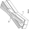
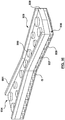
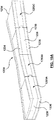
- the special trackwork assembly 20 preferably includes a special trackwork body 22 formed to support wheels of a train (not shown) moving over a running surface portion 24 of an exterior surface 26 of the special trackwork body 22 that generate traffic-related vibrations of the special trackwork body 22 having one or more frequencies of interest.
- the special trackwork assembly 20 includes one or more tuned mass dampers 28 that are secured to the special trackwork body 22 and formed to vibrate, in response to the traffic-related vibrations of the special trackwork body 22, at the frequency (or frequencies, as the case may be) of interest, to at least partially dampen the traffic-related vibrations of the special trackwork body 22.
- vibrations of the special trackwork body 22 generated when the train wheels move over the special trackwork body 22 typically are at, or have, one or more frequencies.
- the frequency of interest or the “target frequency”
- the traffic-related vibrations of the special trackwork body 22 reach a peak amplitude.
- the mass and the stiffness characteristics of the tuned mass damper are determined so that the amplitude of the traffic-related vibrations of the special trackwork body 22 at the frequency of interest or target frequency is lowered.
- the tuned mass damper 28 preferably is formed specifically to dampen the traffic-related vibrations of the special trackwork body 22.
- the main system As is well known in the art, if a single (or multi-) degree of freedom system (the "main system”) is subjected to a periodic load, then the system vibrates. In theory, the vibration amplitude will peak when the frequency of the load is close to the natural frequency (or natural frequencies) of the system. Those skilled in the art would appreciate that, in a complex system, the peak amplitude may occur approximately at the natural frequency of the system. In practice, therefore, the tuned mass damper is configured to dampen the traffic-related vibrations of the special trackwork body 22 at the frequency of interest. A secondary system (in embodiment of the special trackwork assembly 20 described above, the tuned mass damper) may be used to minimize the amplitude of vibration of the main system (i.e., the special trackwork body) in the frequency of interest.
- the main system i.e., the special trackwork body
- the special trackwork body 22 as installed is considered to be the "main system" "M" ( Fig. 28 ). That is, the main system includes the special trackwork body as installed, including the supporting material "Q" (e.g., concrete, and/or aggregate) proximal to the special trackwork body that supports the special trackwork body. In some arrangements (not shown), the special trackwork body may be embedded in supporting material. For example, the main system may include the special trackwork body 22 that is also supported on its sides by concrete (not shown). It will be understood that the main system as illustrated in Fig. 28 is exemplary only. The tuned mass damper 28 is considered to be the "secondary system".
- Q e.g., concrete, and/or aggregate
- the main system may vibrate at a number of frequencies when train wheels roll over it.
- one or more tuned mass dampers 28 preferably are mounted to the special trackwork body 22 in order to minimize the vibration thereof, as will be described.
- the tuned mass damper 28 may be secured to the special trackwork body 22 in various ways. For instance, and as can be seen in Figs. 1A and 1B , in one embodiment, the tuned mass damper 28 preferably is at least partially secured to a bottom surface 32 of the special trackwork body 22.
- the tuned mass damper 28 preferably includes one or more resilient elements.
- the resilient elements are referred to as an upper (or first) resilient element (identified in Fig. 1B by reference numeral 34) and a lower (or second) resilient element (identified in Fig. 1B by reference numeral 36).
- the upper and lower resilient elements have respective preselected stiffnesses.
- the non-resilient element 38 preferably is attached to the special trackwork body 22 via one of the resilient elements (e.g., by the upper resilient element 34 in the embodiment illustrated in Fig. 1B ).
- the non-resilient element 38 preferably has a preselected mass.
- the preselected stiffnesses of the respective resilient elements 34, 36 and the preselected mass of the non-resilient element 38 are selected for causing the tuned mass damper 28 to vibrate at the frequency of interest (or a number of frequencies of interest, as the case may be) in response to the traffic-related vibrations, for at least partially dampening the traffic-related vibrations of the special trackwork body 22.
- the special trackwork assembly 20 optionally may also include a bottom layer 39 ( Fig. 1B ), as will be described.
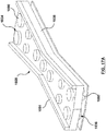
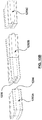
- the special trackwork body 22 may include one or more internal cavities 40 defined by internal walls 41 respectively ( Figs. 3A , 3B , 4 ).
- the tuned mass damper 28 is at least partially secured to the internal wall 41, as will be described.
- the special trackwork assembly 20 preferably includes one or more tuned mass dampers accordingly, i.e., with the tuned mass dampers each being tuned to minimize the amplitude of vibration at a specific frequency respectively.
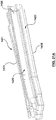
- the tuned mass dampers 28 may be implemented in a wide variety of forms. For instance, as illustrated in Figs. 1A and 1B , the tuned mass damper 28 may be secured to a bottom surface of the special trackwork body 22. In another embodiment, and as can be seen in Figs.
- the special trackwork assembly 20 preferably includes one or more internal tuned mass damper subassemblies (identified collectively by the reference numeral 28 U for convenience, and referred to collectively as an upper tuned mass damper), and one or more lower tuned mass damper subassemblies (identified in Figs. 2A-3A and 4 by the reference numeral 28 L for convenience).
- an upper tuned mass damper subassembly 28 U preferably is mounted in the special trackwork body 22, and the tuned mass damper subassembly 28 L preferably is partially bonded to a bottom surface 32 of the special trackwork body 22.
- the upper tuned mass damper 28 U may be used alone, i.e., the special trackwork assembly 20 may include only the upper tuned mass damper, and have no lower tuned mass damper ( Fig. 3B ).
- the special trackwork assembly 20' preferably includes a steel base plate 39 secured or bonded to the special trackwork body 22.
- the base plate 39 is optional.
- each of the upper and lower tuned mass damper subassemblies 28 U , 28 L may include one or more tuned mass dampers.
- the special trackwork assembly may include only an upper tuned mass damper, or only a lower tuned mass damper.
- each of the tuned mass dampers preferably is tuned to a specific body frequency (or range of body frequencies, as the case may be) in order to dampen the amplitude of vibrations of the special trackwork body at the specific frequency, or over the range of frequencies.
- the lower tuned mass damper preferably includes only one tuned mass damper that includes the upper or first layer 34 including a first resilient material engaged with the bottom surface 32 of the special trackwork body 22 and the lower or second layer 36 including a second resilient material, and spaced apart from the upper layer 34.
- the tuned mass damper 28 L preferably includes the damper mass 38 positioned between, and secured to, the first and second layers 34, 36.
- first and second layers 34, 36 have respective first and second stiffnesses and the damper mass has a preselected mass, selected for causing the tuned mass damper 28 L to vibrate at the frequency of interest, in response to the traffic-related vibrations of the special trackwork body 22, for at least partially dampening the traffic-related vibrations of the special trackwork body.
- the special trackwork assembly 20 preferably also includes a bottom layer or base plate 39 of a suitable non-resilient material, e.g., steel.
- the base plate 39 is optional, and is not part of the lower tuned mass damper subassembly 28 L .
- the base plate 39 may be included in the special trackwork assembly 20 to protect the lower layer 36 of foam against abrasion or rupture, e.g., during installation ( Fig. 3A ).
- the base plate 39 may not be included in the special trackwork assembly 20.
- the upper and lower layers 34, 36 and the damper mass 38 may be made of any suitable materials. Those skilled in the art would appreciate that the upper and lower layers 34, 36 preferably have some elasticity or resilience. As illustrated in Figs. 3A and 4 , in one embodiment, the upper and lower layers 34, 36 preferably are respective unitary sheets of foam, and the damper mass 38 preferably is in the form of a single, unitary mass of a suitable non-resilient material, e.g., steel.
- the foam material may be, for example, urethane foam, or high-density polyurethane foam. It will be understood that the upper and lower layers 34, 36 may be made of the same material, or they may be made of different materials.
- the tuned mass damper 28 L is formed so that it dampens vibration of the special trackwork body 22 at one or more specific (body) frequencies, i.e., resulting from traffic-related vibrations.
- the special trackwork assembly 20 preferably also includes the upper tuned mass damper subassembly 28 U .
- the special trackwork body 22 preferably includes a number of internal cavities 40, each being at least partially defined by the internal walls 41 thereof respectively.
- the upper tuned mass damper subassembly 28 U includes a number of internal tuned mass dampers 42 positioned in the internal cavities 40 respectively.
- each of the internal tuned mass dampers is secured to the special trackwork body 22 via the internal wall 41.
- Each of the internal tuned mass dampers 42 is formed so that it minimizes vibration of the special trackwork body 22 at another specific frequency. That is, it is preferred that the lower tuned mass damper 28 L and each of the internal tuned mass dampers 42 (i.e., the upper tuned mass damper 28 U ) is formed to minimize vibrations of the special trackwork body 22 at a particular frequency respectively.
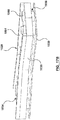
- vibrations having different frequencies may be generated by the train wheels moving over the track body 22 from a first end "Y" to a second end “Z” of the body 22, and vice versa ( Figs. 1A , 2A , 2B ).
- certain special trackwork bodies 22, primarily in North America may be formed to include the internal cavities 40.
- the internal cavities 40 preferably are utilized to provide locations at which the internal tuned mass dampers 42 are individually mounted respectively.
- the upper tuned mass damper 28 U includes all the internal tuned mass dampers 42 positioned in the internal cavities. It is preferred that each of the internal tuned mass dampers 42 includes one or more resilient mounting elements 43 having a preselected stiffness.
- Each of the internal tuned mass dampers 42 preferably also includes an internal tuned damper mass 44 with a preselected mass and secured to the special trackwork body 22 via the resilient mounting elements 43 ( Fig. 3A ).
- the internal tuned mass dampers 42 are formed to vibrate at the frequency of interest in response to the traffic-related vibrations of the special trackwork body, for at least partially dampening the traffic-related vibrations of the special trackwork body 22.
- the resilient mounting material used in the mount 43 may be any suitable material.
- the resilient mounting material preferably is a suitable foam, e.g., urethane foam, or high-density polyurethane foam.
- the mounting element 43 and the damper mass 44 occupy substantially the entire cavity 40.
- the internal tuned mass 44 which is directly engaged only with the mount 43, preferably is also made of any suitable material.
- the internal tuned mass 44 preferably is made of any suitable steel.
- the characteristics and dimensions of the upper and lower layers 34, 36 and the damper mass 38 are determined using techniques known in the art, to achieve the desired damping effect at the selected frequency (or frequencies), taking the relevant characteristics of the materials into account.
- the characteristics and dimensions of the mounts 43 and the internal tuned masses 44 of a particular internal tuned mass damper 42 are determined using techniques known in the art in view of the frequency of the vibrations that are to be damped by the internal tuned mass damper 42, taking the relevant characteristics of the materials into account.
- the upper and lower tuned mass damper subassemblies 28 U , 28 L preferably are formed to cooperate to minimize the vibrations that are generated in the special trackwork body 22 when the train wheels move over it. As noted above, this is achieved by determining the various frequencies of the vibrations generated when the train wheels roll over the special trackwork body 22, and providing one or more tuned mass dampers that are tuned to selected ones of frequencies, to modify or attenuate the amplitudes of the vibrations to which special trackwork body 22 is subjected at such frequencies.
- the internal tuned mass 44 preferably is substantially surrounded by the mount 43.
- the cavity 40 is substantially filled with the foam mount 43, except to the extent that a certain volume inside the cavity 40 is occupied by the internal tuned mass 44.
- the mount in the cavity is made of resilient material other than foam, unoccupied spaces may be provided inside the cavity.
- the special trackwork assembly 20 preferably is provided without rubber encapsulation.
- a special trackwork assembly 20" of the invention preferably is encapsulated in a rubber covering 45.
- the exterior surface 26 of the special trackwork assembly 20 preferably includes the running surface portion 24, over which the train wheels (not shown) run.
- the exterior surface 26 also includes a non-running surface portion 46 ( Fig. 1A ).
- the special trackwork body 22 is supported by supporting material 48 ( Fig. 8 ).
- the non-running surface portion 46 is covered by the layer 45 of electrically insulating material (e.g., rubber) for substantially electrically isolating the special trackwork body 22 relative to the supporting material 48.
- special trackwork refers generally to any railway track other than “plain” or straight track that is not curved or fabricated before it is laid, for instance, turnouts, crossovers, track crossings, derails, diamond crossings, and sliding rail joints. Accordingly, although only frogs are shown in the drawings, it will be understood that the special track included in the special trackwork assembly of the invention may include other types of special track, e.g., switches.
- the invention preferably includes a tuned mass damper 28 for damping traffic-related vibrations of the special trackwork body 22 generated by train wheels rolling over the special trackwork body.
- the traffic-related vibrations have one or more frequencies of interest, as described above.
- the tuned mass damper 28 preferably includes one or more resilient elements including one or more resilient materials. Each resilient element has a preselected stiffness.
- the tuned mass damper 28 preferably also includes one or more non-resilient elements 38 including one or more non-resilient materials that is at least partially connected to the special trackwork body 22 via one of the resilient elements.
- the non-resilient element has a preselected mass.
- the preselected stiffness of the resilient element and the preselected mass of the non-resilient element preferably are selected to permit the tuned mass damper to vibrate, in response to the traffic-related vibrations transmitted thereto, at the frequency of interest, to dampen the traffic-related vibrations of the special trackwork body.
- An embodiment of a method of the invention includes providing the resilient element(s), and providing the non-resilient element(s). Via the resilient element, the non-resilient element is connected to the special trackwork body, to cause the non-resilient element and the resilient element to vibrate, in response to the vibrations of the special trackwork body, at the frequency of interest, for at least partially dampening the traffic-related vibrations of the special trackwork body.
- the upper tuned mass damper subassembly 128 U preferably includes a number of internal tuned mass dampers 142.
- Each of the internal tuned mass dampers 142 is tuned to attenuate vibration of the special trackwork body 22 at a selected frequency.
- a mount 143 includes two parts, identified for convenience as "A" and "B" in Fig. 6C .
- the mounts 143 and the respective masses 144 may be made of any suitable materials respectively. In one embodiment, it is preferred that the parts "A" and "B" of the mounts 143 are made of a suitable rubber.
- the internal tuned mass 144 preferably is suspended between the parts "A" and “B" of the mount 143. It will be understood that the mounts 143 are secured to the special trackwork body 22 in the internal cavities 140, i.e., each of the parts "A” and “B” is secured to the special trackwork body 22, as well as to the internal tuned mass 144.
- the mount 143 may be provided in any suitable configuration.
- An example of an alternative configuration is illustrated in Fig. 6D , in which the mount 143' includes only one rubber mount "A 1 " connected to an upper internal wall 141 of the internal cavity 140, and from which the internal damper mass 144 is suspended.
- the special trackwork assembly 120 preferably also includes a lower tuned mass damper 128 L that is generally similar to the lower tuned mass damper 28 L of the special trackwork assembly 20.
- the lower tuned mass damper subassembly 128 L has upper and lower layers 134, 136 and a damper mass 138 therebetween.
- the upper and lower layers 134, 136 preferably are made of any suitable resilient material, as noted above.
- the tuned damper mass 138 may be made of any suitable material.
- the tuned damper mass 138 is made of steel.
- the lower tuned mass damper subassembly 128 L may, if desired, include a number of tuned mass dampers. Such an embodiment is described below.
- the special trackwork assembly 120 preferably also includes a base plate 139. As described above, the base plate 139 is optional.
- FIG. 7A-7E An alternative embodiment of the special trackwork assembly 220 of the invention including upper and lower tuned mass damper subassemblies 228 U , 228 L is illustrated in Figs. 7A-7E .
- mounts 243 preferably are generally similar to the mounts 143, and it is also preferred that the mounts 243 are made of any suitable resilient material.
- the mounts 243 may be made of a suitable rubber.
- an internal tuned mass 244 is held by the mount 243. Accordingly, it can be seen that, in the embodiment illustrated in Figs. 7A-7E , the internal tuned mass dampers 242 are similar to the upper tuned mass dampers 142.
- the primary differences between the special trackwork assembly 220 and the special trackwork assembly 120 are in the differences between the respective lower tuned mass damper subassemblies 228 L and 128 L .
- the lower tuned mass damper 228 L preferably includes upper and lower layers 234, 236 that include strips 237 of any suitable resilient material, positioned with element gaps "G" therebetween ( Figs. 7D , 7E ).
- the damper mass 238 is positioned between the upper and lower layers 234, 236.
- the strips 237 may be made of rubber.
- the damper mass 238 preferably is any suitable material, e.g., steel.
- the special trackwork assembly 220 includes a base plate 239. As described above, the base plate 239 is optional.
- the sizes, configurations, and physical characteristics of the resilient strips 237 and the element gaps "G" are determined in accordance with the frequencies of the vibration(s) that are to be damped by the lower tuned mass damper 228 L .
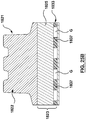
- FIG. 8 An example of an installation of the special trackwork assembly 20 of the invention is illustrated in Fig. 8 .
- the special trackwork assembly 20 is supported by, and secured to, a base element 50 that is supported by posts 52 above a foundation 54.
- the base element 50 is held substantially horizontal by the posts 52.
- the special trackwork assembly 20 preferably is secured to the base element 50 by a lateral support brace 56.
- FIG. 8 it can also be seen that additional track elements 58, 60 preferably are positioned on each side of the special trackwork assembly 20, for supporting the train wheels (not shown) that are not supported by the special trackwork body 22.
- the installation is completed by introducing concrete 48, up to the level identified as "X" in Fig. 8 .
- the track elements 58, 60 are supported on brackets or fittings 62 that are secured to the base element 50.
- the brackets 62 preferably include openings 64 that permit the concrete, when poured, to flow inside the fittings 62, to secure the track elements 58, 60, once cured.
- the special trackwork assembly 20 once partially embedded in concrete (as illustrated in Fig. 8 ), transmits substantially fewer vibrations to the surrounding ground than the prior art special trackwork, and the extent to which the concrete is subjected to significant vibrations is minimized accordingly.
- the special trackwork assembly of the invention may be installed in various ways, e.g., the special trackwork assembly may be installed by direct fixation fasteners, or with ties on track ballast. That is, the supporting material 48 may be any suitable material, and need not necessarily be concrete. Accordingly, the installation illustrated in Fig. 8 will be understood to be exemplary only.
- the lower tuned mass damper subassemblies 28 L , 128 L , 228 L may, alternatively, each include more than one tuned mass damper.
- the multiple tuned mass dampers thereof are respectively tuned to attenuate vibrations at a number of respective frequencies, so that the internal tuned mass dampers and the lower tuned mass dampers respectively minimize vibrations at a number of frequencies. Examples of lower tuned mass damper subassemblies that include more than one tuned mass damper are shown in Figs. 10-12 , described below.
- the special trackwork assembly may alternatively include only the upper tuned mass damper(s), as illustrated in Fig. 3B .
- a special trackwork body 322 of the special trackwork assembly 320 does not include cavities.
- the special trackwork assembly 320 preferably includes only a lower tuned mass damper 328 that includes upper and lower layers 334, 336 of resilient material, and a damper mass 338. In this embodiment, the upper and lower layers 334, 336 have different thicknesses.
- the tuned mass damper 328 is tuned to dampen the vibrations generated at a particular frequency upon train wheels passing over the special trackwork body 322, as described above. In the example illustrated, because there is no "upper" tuned mass damper, only the relevant characteristics of the tuned mass damper 328 are pertinent.
- the special trackwork assembly 320 is shown as also including a base plate 339, which is optional.
- the special trackwork assembly preferably includes a number of tuned mass dampers that are formed for dampening the traffic-related vibrations at selected body frequencies.
- the tuned mass dampers are at least partially separated from each other by gaps, i.e., cavities with ambient air therein.
- gaps i.e., cavities with ambient air therein.
- Fig. 10 discloses another alternative embodiment of the special trackwork assembly 420 of the invention.
- the special trackwork assembly 420 includes a special trackwork body 422 that does not include cavities.
- the special trackwork assembly 422 includes a tuned mass damper subassembly 428 that includes a number of tuned mass dampers, i.e., a first tuned mass damper 466 surrounded by a second tuned mass damper 468.
- the first and second tuned mass dampers 466, 468 are positioned so that the second tuned mass damper 468 substantially surrounds the first tuned mass damper 466.
- the first and second tuned mass dampers 466, 468 preferably are separated by a gap 470. Because of the gap 470, the first and second tuned mass dampers may function substantially independently of each other. Because the first and second tuned mass dampers 466, 468 are separated by the gap 470, they are tuned to dampen vibrations at different frequencies respectively.
- the special trackwork assembly 420 preferably includes a number of tuned mass dampers that are at least partially separated from each other by the gaps therebetween, each of the tuned mass dampers being formed for at least partially dampening the traffic-related vibrations at the frequency (or frequencies) of interest.
- the gaps between the tuned mass dampers may be filled (or partially filled) by any suitable resilient material, e.g., by a suitable foam material.
- the first tuned mass damper 466 preferably includes first and second layers 434, 436 separated by a damper mass 438.
- the second tuned mass damper 468 also preferably includes upper and lower layers 434', 436' separated by a damper mass 438'.
- the special trackwork assembly 420 preferably also includes optional base plates 439, 439', respectively positioned on the tuned mass dampers 466, 468.
- composition and the configuration of the tuned mass dampers 466, 468 are determined so as to minimize vibration of the special trackwork body 22 at different predetermined frequencies of interest.
- the special trackwork assembly 520 includes a tuned mass damper subassembly 528 that includes three tuned mass dampers, identified respectively by reference numerals 572, 574, and 576 ( Figs. 11A , 11B ).
- the special trackwork assembly 520 preferably includes the special trackwork body 522.
- each of the first, second, and third tuned mass dampers 572, 574, 576 includes upper and lower layers that have different thicknesses respectively.
- the damper mass in each of the first, second and third tuned mass dampers 572, 574, 576 also has a slightly different thickness.
- the upper and lower layers of the resilient material in the first tuned mass damper 572 are identified by reference numerals 534, 536, and the damper mass is identified by the reference numeral 538.
- the first and second tuned mass dampers 572, 574 are separated by a gap 577, and the second and third tuned mass dampers 574, 576 are separated by a second gap 578.
- Each of the first, second, and third tuned mass dampers 572, 574, 576 is tuned to dampen respective vibrations at one or more frequencies respectively.
- a base plate 580 is included in the special trackwork assembly 520 and engages all of the tuned mass dampers 572, 574, 576. As noted above, the base plate 580 is optional.
- the special trackwork assembly 620 preferably includes the special trackwork body 622.
- a tuned mass damper subassembly 628 preferably includes first through fourth tuned mass dampers thereof, identified by reference numbers 682, 684, 686, and 688 respectively.
- the first tuned mass damper 682 includes upper and lower layers 634, 636 separated by a damper mass 638.
- the second tuned mass damper 684 includes upper and lower layers 634', 636' separated by a damper mass 638'.
- the third tuned mass damper 686 preferably includes upper and lower layers 634", 636" separated by a damper mass 638".
- the fourth tuned mass damper 688 preferably also includes upper and lower layers 634'", 636'" and a damper mass 638'" located therebetween. It will be understood that the upper and lower layers of each of the tuned mass dampers may or may not have the same thickness, and the damper mass (preferably, steel) in each of the tuned mass dampers 682, 684, 686, 688 also may or may not have the same thickness.
- the special trackwork assembly 620 preferably includes first, second, third and fourth base plates 639, 639', 369", 369'” respectively, secured to the respective tuned mass dampers 682, 684, 686, 688, ( Fig. 12 ). It will be understood that the base plates 639, 639', 369", 369'" are optional.
- the first and second tuned mass dampers 682, 684 are separated by a gap identified in Fig. 12 as 6G 1 .
- the first and third tuned mass dampers 682, 686 are separated by a gap identified as 6G 2
- the first and fourth tuned mass dampers 682, 688 are separated by a gap identified as 6G 3 . It will be understood that, at their respective upper ends (not shown), the first through fourth tuned mass dampers 682, 684, 686, and 688 are secured to the special trackwork body 622.
- each of the tuned mass dampers 682, 684, 686, 688 is tuned to dampen vibrations at a different frequency respectively.
- the special trackwork assemblies 320, 420, 520, 620 are illustrated without rubber encapsulation. It will be understood that the special trackwork assembly of the invention may be provided with or without a rubber encapsulation.
- a special trackwork assembly 620' of the invention, with the rubber encapsulation 45, is illustrated in Fig. 13 .
- the invention also includes embodiments in which the tuned mass damper of the invention is configured for use with a special trackwork body.
- Different embodiments of the tuned mass damper of the invention are illustrated in Figs. 14A-19B .
- the tuned mass damper 728 ( Figs. 14A , 14B ) is for dampening vibrations of a special trackwork body (not shown in Figs. 14A , 14B ) as train wheels roll over the special trackwork body.
- the tuned mass damper 728 includes one or more resilient elements 734, 736 made of resilient material(s), and one or more non-resilient elements 738 made of non-resilient material(s) ( Figs. 14A , 14B ).
- the resilient elements 734, 736 and the non-resilient element 738 are formed to dampen the vibrations of the special trackwork body 22 (not shown in Figs. 14A , 14B ) when the tuned mass damper 728 is secured to the special trackwork body.
- a base plate 739 is optional ( Figs. 14A , 14B ).
- the tuned mass damper subassembly 728' illustrated in Fig. 14B is the same as the tuned mass damper subassembly 728 that is illustrated in Fig. 14A , except that the tuned mass damper subassembly728' is encapsulated in rubber, identified by reference numeral 45 in Fig. 14B .
- the tuned mass damper 828 preferably includes upper and lower layers 834, 836 of resilient material(s) separated by a damper mass 838 of any suitable generally non-resilient material, e.g., steel.
- the upper layer 834 preferably includes a number of elements 890 that are positioned to engage the special trackwork body (not shown in Fig. 15 ).
- the intermediate elements 890 preferably are positioned on the damper mass 838.
- the elements 890 are made of any suitable resilient material, e.g., rubber.
- the lower layer 836 may be made of any suitable resilient material, e.g., a suitable foam material. It is also preferred that the tuned mass damper subassembly 828 includes a guide element 891, for guiding the special trackwork (not shown in Fig. 15 ) into position, to engage the tuned mass damper subassembly 828 properly, i.e., when the special trackwork body is mounted onto the tuned mass damper subassembly 828. A base plate 839 is optional.
- a tuned mass damper subassembly 928 illustrated therein is similar to the tuned mass damper subassembly 828 illustrated in Fig. 15 .
- the primary difference between the tuned mass dampers 928 and 828 is that the tuned mass damper 928 has a lower layer 936 that includes strips 937 of rubber or any other suitable resilient material spaced apart from each other to define element gaps "G" therebetween.
- the tuned mass damper 928 preferably also includes an upper layer 934 and a damper mass 938 positioned between the upper and lower layers 934, 936.
- the upper layer 934 includes elements 990.
- the tuned mass damper subassembly 928 preferably includes a guide element 991.
- a base plate 939 is optional.
- the tuned mass damper subassembly 1028 preferably includes an upper layer 1034 with elements 1090, and a lower layer 1036.
- the lower layer 1036 preferably includes a number of elements 1092 that are similar to the elements 1090 of the upper layer 1034, in that they are disc-like elements made of a resilient material.
- the elements 1092 and the elements 1090 are made of any suitable resilient material.
- the elements 1092 and the elements 1090 may be made of a suitable rubber.
- the tuned mass damper 1028 preferably also includes a mass 1038 positioned between the upper and lower layers 1034, 1036.
- the tuned mass damper subassembly 1028 preferably also includes a guide element 1091.
- a base plate 1039 is optional.
- FIG. 18 Another alternative embodiment of the tuned mass damper subassembly 1128 includes a tuned mass damper 1128 is illustrated in Fig. 18 .
- an upper layer 1134 includes elements 1190 that are strips of rubber or any other suitable resilient material, defining element gaps "G" therebetween.
- a lower layer 1136 of the tuned mass damper 1128 includes strips of rubber or any other suitable resilient material that also define element gaps "G” therebetween.
- the upper layer 1134 and the lower layer 1136 are made of a suitable resilient material.
- the tuned mass damper 1128 preferably also includes a mass 1138 located between the upper layer 1134 and the lower layer 1136. It is also preferred that the tuned mass damper subassembly 1128 includes a guide element 1191.
- a base plate 1139 is optional.
- Figs. 19A and 19B An alternative embodiment of the tuned mass damper subassembly 1228 is disclosed in Figs. 19A and 19B .
- the tuned mass damper subassembly 1228 is formed when three segments 1293A, 1293B, 1293C are fitted together, in an assembled condition.
- the tuned mass damper subassembly 1228 is illustrated in the assembled condition in Fig. 19A .
- Fig. 19A when the segments 1293A, 1293B, and 1293C are in the assembled condition, a tuned mass damper 1228 is formed.
- the tuned mass damper 1228 preferably has an upper layer 1234, a lower layer 1236, and a mass damper 1238 positioned between the upper and lower layers 1234, 1236.
- the tuned mass damper 1228 is also illustrated, in an unassembled condition, in Fig. 19B .
- the tuned mass damper 1228 includes suitable means for connecting the segments thereof together.
- such means may include a tab 1294 that cooperatively fits into a slot 1296 in a neighboring segment ( Figs. 19A , 19B ).
- a base plate 1239 is optional.
- the special trackwork assembly 1320 (including a special trackwork body 1322) is illustrated in Figs. 20A and 20B . As can be seen in those views, the special trackwork assembly 1320 does not include a base plate. Preferably, the special trackwork assembly 1320 includes a lower tuned mass damper 1328 L that includes upper and lower layers 1334, 1336 of resilient material(s) and a damper mass 1338 positioned therebetween.
- the special trackwork assembly 1320 preferably also includes an upper tuned mass damper subassembly 1328 U , which includes a number of internal mass dampers 1342.
- a vibration isolator is coupled with a special trackwork body to at least partially dissipate traffic-related vibrations. These embodiments are illustrated in Figs. 21A-25C .
- a special trackwork assembly 1421 of the invention that is connected to a surrounding structure "S" preferably includes a vibration isolator 1423 and a special trackwork body 1422 for supporting wheels of a train (not shown) moving over a running surface portion 1424 of an exterior surface 1426 of the special trackwork body 1422 that generate traffic-related vibrations in the surrounding structure "S", in the absence of the vibration isolator 1423, at a dominant frequency ( Fig. 21A ).
- the special trackwork assembly 1421 also includes the vibration isolator 1423, which has one or more non-resilient isolator elements 1425 ( Figs. 21B , 21C ).
- the non-resilient isolator element 1425 preferably has a predetermined isolator mass that is bonded with the special trackwork body 1422 to form a combined body 1431 having a preselected total body mass.
- the vibration isolator 1423 also includes one or more resilient isolator elements 1433 at least partially supporting the combined body 1431.
- the resilient isolator element 1433 has a preselected isolator stiffness that is selected to permit the combined body 1431 and the resilient isolator element 1433 to vibrate, in response to movement of the train wheels over the running surface portion 1424, to at least partially isolate the surrounding structure "S" from the traffic-related vibrations, at a predetermined isolation frequency that is equal to or less than the dominant frequency.
- the non-resilient isolator element 1425 may be made of any suitable material.
- the non-resilient isolator element 1425 may be steel, as shown in Fig. 21B .
- the non-resilient isolator element 1425 may be bonded to the special trackwork body 1422 in any suitable manner.
- the non-resilient isolator element 1425 preferably is welded to the special trackwork body 1422.
- the resilient isolator element 1433 is made of any suitable resilient material.
- rubber or foam would be suitable resilient materials.
- the special trackwork assembly 1421 includes an optional base plate 1439, to protect the resilient isolator element 1433, especially during installation.
- the surrounding structure "S” may be any material or structure outside the special trackwork assembly 1421 engaged or connected (indirectly or otherwise) with the special trackwork assembly 1421. To the extent that the surrounding structure is isolated from the traffic-related vibrations, the surrounding structure is unaffected by such vibrations, i.e., the vibrations are not transmitted to the surrounding structure.
- the movement of the train wheels over the running surface portion of the special trackwork body results in traffic-related vibrations generated in the surrounding structure that have a peak amplitude at a dominant (or "critical") frequency.
- the peak amplitude and the dominant frequency may be determined in various ways, as would be appreciated by those skilled in the art.
- An isolation frequency is then determined according to the dominant frequency using methods known to those skilled in the art. The isolation frequency is equal to or less than the dominant frequency, and is lower than a natural frequency of the main system.
- the special trackwork body as installed, in the absence of the vibration isolator forms a main system "M" that has a main natural frequency.
- the vibration isolator is added to the main system "M" (i.e., the main system being the special trackwork as installed, but in the absence of the vibration isolator) to lower the main natural frequency of the main system by adding mass to it, and by lowering the stiffness thereof.
- the frequency can be lowered from the natural frequency to the predetermined isolation frequency by adding the isolator mass to the main system (i.e., to the special trackwork body), and by decreasing the stiffness of the main system, by adding the resilient isolator element to the main system.
- a modified main system is created by the addition of the vibration isolator to the special trackwork body.
- the surrounding structure receives less traffic-related vibrations because the main natural frequency of the main system has been lowered, so that the surrounding structure "S" is at least partially isolated from the traffic-related vibrations.
- the special trackwork assembly may include one or more tuned mass dampers, as well as the vibration isolator.
- the special trackwork assembly 1421 preferably also includes a tuned mass damper 1428 that includes one or more internal tuned mass dampers 1442, i.e., in addition to the vibration isolator 1423.
- the internal tuned mass damper 1442 preferably includes one or more resilient elements 1443 having a preselected stiffness and one or more non-resilient elements 1444 having a predetermined damper mass secured to the special trackwork body 1422 via the resilient element 1443. It will be understood that the vibration isolator and the main system "M" have a main combination natural frequency.
- the preselected stiffness and the preselected damper mass are selected to permit the tuned mass damper 1442 to vibrate at a frequency of interest based on the main combination natural frequency of the vibration isolator and the main system, to at least partially dampen the traffic-related vibrations.
- the special trackwork body as installed may be considered to be the main system, for the purposes of analyzing the traffic-related vibrations of the special trackwork body 22.
- the combination of the special trackwork body and the vibration isolator may be considered another, "modified", main system.
- the modified main system vibrates at the isolation frequency, to at least partially isolate the surrounding structure "S" from the traffic-related vibrations.
- the modified main system may, when subjected to traffic-related vibrations, have a modified frequency of interest at which a peak amplitude of the traffic-related vibrations of the modified main system occurs.
- a tuned mass damper tuned for the (modified) frequency of interest for the modified main system (i.e., the vibration isolator and the special trackwork body), may be added.
- the tuned mass damper dampens the traffic-related vibrations of the modified main system.
- a special trackwork assembly 1521 of the invention preferably includes a vibration isolator 1523 in which a combined body 1531 thereof preferably is formed as an integral element, e.g., by casting.
- the combined body 1531 preferably includes a special trackwork body portion 1522 and a non-resilient isolator element portion 1525.
- the vibration isolator 1523 preferably includes a resilient isolator element 1533. The total body mass of the combined body 1531 and a predetermined stiffness of the resilient element 1533 are determined so that the vibration isolator 1523 at least partially dissipates the traffic-related vibrations.
- the special trackwork assembly 1521 may include a tuned mass damper 1528.
- the tuned mass damper 1528 may include a number of internal tuned mass dampers 1542 ( Fig. 22C ). It will be understood that the combined body 1531 may include a number of internal cavities 1540 along its length, with the internal tuned mass dampers 1542 positioned in the internal cavities, as shown in Fig. 22D .
- Each internal cavity 1540 is at least partially defined by one or more internal walls 1541 respectively ( Fig. 22C ).
- Each internal tuned mass damper 1542 preferably includes one or more resilient internal elements 1543 associated therewith having a preselected internal element stiffness. It is also preferred that each internal tuned mass damper 1542 includes an internal tuned damper mass 1544 having a preselected internal damper mass secured to the internal wall 1541 via the resilient internal element 1543 associated with each internal tuned mass damper 1542 respectively, whereby, in response to the traffic-related vibrations, the internal tuned mass damper 1542 vibrates at the frequency of interest based on the main combination natural frequency of the vibration isolator and the main system, to at least partially dampen the traffic-related vibrations.
- a method of the invention for at least partially isolating traffic-related vibrations of a special trackwork body preferably includes providing one or more resilient isolator elements, each having a preselected isolator stiffness, and providing one or more non-resilient isolator elements, each having a preselected isolator mass.
- the non-resilient element preferably is bonded to the special trackwork body to form a combined body having a preselected total body mass.
- the resilient isolator element and the combined body are permitted to vibrate in response to the traffic-related vibrations to at least partially isolate the surrounding structure "S" from the traffic-related vibrations at an isolation frequency that is equal to or less than the dominant frequency.
- the combined body may be an integral mass in which the special trackwork body and the non-resilient isolator element are formed together (e.g., by casting).
- a special trackwork assembly 1621 preferably includes a vibration isolator 1623 having a non-resilient isolator element 1625 bonded to the special trackwork body 1622 to form a combined body 1631 ( Fig. 23B ), and a resilient isolator element 1633.
- Such bonding may be effected using any suitable method, e.g., welding.
- the special trackwork assembly 1621 preferably also includes one or more tuned mass dampers.
- a tuned mass damper 1628' shown in Figs. 23B and 23C is a bottom-mounted tuned mass damper.
- the special trackwork assembly 1621 is shown in which the internal tuned mass damper 1642 is included. It will be understood that the special trackwork body 1622 may include a number of internal cavities along its length, in which a number of the internal tuned mass dampers 1642 may be located, as described above.
- a special trackwork assembly 1721 preferably includes a vibration isolator 1723 having a combined body 1731 formed as an integral element (e.g., by casting) that includes a special trackwork body portion 1722 and a non-resilient isolator element portion 1725, and a resilient isolator element 1733 ( Figs. 24B , 24C ).
- the special trackwork assembly 1721 preferably also includes one or more tuned mass dampers.
- a tuned mass damper 1728' is a bottom-mounted tuned mass damper ( Figs. 24B , 24C ).
- the special trackwork assembly 1721 is shown in which the internal tuned mass damper 1742 is included. It will be understood that the special trackwork body 1722 may include a number of internal cavities along its length, in which a number of the internal tuned mass dampers 1742 may be located, as described above.
- a special trackwork assembly 1821 preferably includes a vibration isolator 1823 having a non-resilient isolator element 1825 bonded to the special trackwork body 1822 and a resilient isolator element 1833. Such bonding may be effected using any suitable method, e.g., welding.
- the special trackwork assembly 1821 preferably also includes one or more tuned mass dampers.
- the resilient isolator element 1833 includes strips 1837 of any suitable resilient material with element gaps "G" therebetween.
- the strips 1837 may be made of a suitable rubber.
- Fig. 25C an embodiment of the special trackwork assembly 1821 is shown in which the internal tuned mass damper 1842 is included. It will be understood that the special trackwork body 1822 may include a number of internal cavities along its length, in which a number of the internal tuned mass dampers 1842 may be located, as described above.
- the tuned mass damper may or may not extend along the entire length of the special trackwork body.
- the characteristics of the tuned mass damper may be tailored as required, i.e., by varying the length of the tuned mass damper as required.
- a special trackwork assembly 1920 of the invention is illustrated in Fig. 26 .
- the special trackwork assembly 1920 preferably includes a special trackwork body 1922 and a tuned mass damper 1928.
- the tuned mass damper 1928 does not extend along the entire length of the special trackwork body 1922.
- the vibration isolator may or may not extend along the entire length of the special trackwork body. In this way, the characteristics of the vibration isolator may be tailored as required, i.e., by varying the length of the vibration isolator as required.
- a special trackwork assembly 2021 of the invention is illustrated in Fig. 27 .
- the special trackwork assembly 2021 preferably includes a special trackwork body 2022 and a vibration isolator 2023. As can be seen in Fig. 27 , the vibration isolator 2023 does not extend along the entire length of the special trackwork body 2022.
- the tuned mass damper or the vibration isolator may be positioned relative to the special trackwork body in various ways.
- the non-resilient isolator element instead of bonding the non-resilient isolator element to a bottom surface of the special trackwork body, the non-resilient isolator element may be bonded to an exterior side of the special trackwork body. It will be understood that the illustrations of the various embodiments described herein are exemplary only.
Description
- The present invention is related to a trackwork assembly including a trackwork body and one or more tuned mass dampers and further related to a method of damping vibrations of a trackwork body.
- At intersections of railway track (e.g., for streetcars), various types of rails known as "special trackwork" are required. For example, the special trackwork may be designed to enable two substantially straight tracks to intersect (i.e., the special trackwork may be a frog), or to provide curved track around a street corner, to guide the streetcar from one street to another. The special trackwork may include switches. Segments of special trackwork often are formed (e.g., cast, or machined) specifically for a particular intersection. As is known, the segments typically are attached to other segments of special trackwork (or to straight track connecting with the special trackwork), e.g., by means of fish plates or joint bars, or welding.
- Special trackwork may be installed in various ways. For example, the special trackwork in a municipal street railway may be attached to cross ties so that the special trackwork is properly located, and concrete is then backfilled around the track, to cover the railway ties and to provide a generally level area in the intersection, i.e., between the rails and on both sides of the track. As is known, the cross ties may be made of various materials. Typically, if cross ties are used, they are positioned directly on ballast or embedded in concrete. In the prior art, special trackwork also may be positioned or embedded in concrete alone, i.e., in the absence of cross ties.
- As is well known in the art, vibrations generated by train movement over the track generally appear to be less problematic for straight track. It is believed that, because the straight track is more flexible, less vibration is transmitted from the straight track to the ground supporting it.
- There appear to be two reasons for the more serious vibration issues that arise in connection with special trackwork. First, each piece of special trackwork typically is relatively short in length and includes additional elements (i.e., in addition to the rail track typically itself), so that the special trackwork is generally wider than straight track. Because special trackwork is shorter and thicker than straight track, it tends to be stiffer (less flexible) than straight track.
- Second, special trackwork is more likely to be subjected to dynamic impact loading (e.g., due to the train turning a corner, guided by the special trackwork) than straight track. Accordingly, the loads to which special trackwork is subjected are frequently greater than those to which straight track is subjected.
- In any event, the known special trackwork vibrates and transmits forces to surrounding structures when a streetcar or train passes over it, more so than straight track, and this excessive vibration and the transmitted forces lead to undesirable consequences. For instance, the excessive vibration may be a nuisance to those living or working nearby, and/or to passengers. Also, where the special trackwork is embedded in concrete, the concrete often breaks because of the excessive vibrations, leading to other problems at the intersection. Because the surrounding concrete is cracked due to the excessive vibrations, significant maintenance and repair costs typically are incurred in connection with the concrete surrounding the special trackwork in this type of installation.
- The prior
art documents DE 42 07 334 A1 ,GB 1 574 192 A EP 1 657 362 A1 andUS 2010/258647 A1 refer to various solutions for damping vibrations in a railway trackwork. - For the foregoing reasons, there is a need for a system and a method that overcomes or mitigates one or more of the disadvantages or defects of the prior art. Such disadvantages or defects are not necessarily included in those described above.
- In its broad aspect, the invention provides a special trackwork assembly including a special trackwork body formed to support wheels of a train moving over a running surface portion of an exterior surface of the special trackwork body that generate traffic-related vibrations of the special trackwork body having one or more frequencies of interest. The special trackwork assembly also includes one or more tuned mass dampers secured to the special trackwork body and formed to vibrate, in response to the traffic-related vibrations of the special trackwork body, at the frequency of interest, to at least partially dampen the traffic-related vibrations of the special trackwork body.
- In another aspect, the invention provides a tuned mass damper for damping traffic-related vibrations of a special trackwork body generated by train wheels rolling over the special trackwork body, the traffic-related vibrations having at least one frequency of interest. The tuned mass damper includes one or more resilient elements including one or more resilient materials having a preselected stiffness. The tuned mass damper also includes one or more non-resilient elements including one or more non-resilient elements that are at least partially connected to the special trackwork body via the resilient element(s). The non-resilient element has a preselected mass. The preselected stiffness of the resilient element and the preselected mass of the non-resilient element are selected to permit the tuned mass damper to vibrate, in response to the traffic-related vibrations transmitted thereto, at the frequency of interest, to at least partially dampen the traffic-related vibrations of the special trackwork body.
- In another of its aspects, the invention provides a method of dampening vibrations of the special trackwork body formed to support wheels of a train rolling of a running surface of the special trackwork body that generate traffic-related vibrations of the special trackwork body having one or more frequencies of interest. The method includes providing one or more resilient elements having a preselected stiffness, and providing one or more non-resilient elements having a preselected mass. Via the resilient element, the non-resilient element is connected to the special trackwork body, to permit the non-resilient element and the resilient element to vibrate, in response to the vibrations of the special trackwork body, at the frequency of interest, for at least partially dampening the traffic-related vibrations of the special trackwork body.
- According to a further aspect which does not belong to the present invention, this disclosure describes a special trackwork assembly connected with a surrounding structure. The special trackwork assembly includes a vibration isoloator and a special trackwork body for supporting wheels of a train moving over a running surface portion of an exterior surface of the special trackwork body that generate traffic-related vibrations in the surrounding structure, in the absence of the vibration isolator, at a dominant frequency. The vibration isolator includes a non-resilient isolator element having a predetermined isolator mass that is bonded with the special trackwork body to form a combined body having a preselected total body mass. The vibration isolator also includes one or more resilient isolator at least partially supporting the combined body. The resilient isolator element has a preselected isolator stiffness that is selected to permit the combined body and the resilient element to vibrate, in response to the movement of the wheels of the train over the running surface portion, to at least partially isolate the surrounding structure from the traffic-related vibrations at a predetermined isolation frequency that is equal to or less than the dominant frequency.
- According to a further aspect which does not belong to the present invention, this disclosure describes a special trackwork assembly connected to a surrounding structure. The special trackwork assembly includes a vibration isolator and a special trackwork body for supporting wheels of a train moving over a running surface portion of an exterior surface of the special trackwork body that generate traffic-related vibrations in the surrounding structure, in the absence of the vibration isolator, at a dominant frequency. The special trackwork body as installed, in the absence of the vibration isolator, forming a main system. The vibration isolator includes a non-resilient isolator element having a predetermined isolator mass that is bonded with the special trackwork body to form a combined body having a predetermined total body mass. The vibration isolator also includes one or more resilient isolator elements at least partially supporting the combined body. The resilient isolator element has a preselected isolator stiffness selected to permit the combined body and the resilient isolator element to vibrate, in response to the movement of the wheels of the train over the running surface portion, to at least partially isolate the surrounding structure from the traffic-related vibrations at a predetermined isolation frequency that is equal to or less than the dominant frequency. The vibration isolator and the main system have a main combination natural frequency. The special trackwork assembly also includes one or more tuned mass dampers. Each tuned mass damper includes one or more resilient elements having a preselected stiffness and one or more non-resilient elements having a predetermined damper mass and secured to the special trackwork body via the resilient element(s). The preselected stiffness and the preselected damper mass are selected to permit the tuned mass damper to vibrate at a frequency of interest based on the main combination natural frequency of the vibration isolator and the main system, to at least partially dampen the traffic-related vibrations.
- According to a further aspect which does not belong to the present invention, this disclosure describes a vibration isolator for at least partially isolating a surrounding structure that is connected to a special trackwork body over which train wheels roll to generate traffic-related vibrations in the surrounding structure, the traffic-related vibrations having a dominant frequency in the absence of the vibration isolator. The special trackwork body has a body mass. The vibration isolator includes one or more non-resilient isolator elements, each having a predetermined isolator mass, for bonding with the special trackwork body to form a combined body having a total body mass. The vibration isolator also includes one or more resilient isolator elements at least partially supporting the combined body. The resilient isolator element has a preselected isolator stiffness that is selected to permit said at least one non-resilient isolator element and the combined body to vibrate, in response to the movement of the train wheels over the special trackwork body, to at least partially isolate the surrounding structure from the traffic-related vibrations at a predetermined isolation frequency that is equal to or less than the dominant frequency.
- According to a further aspect which does not belong to the present invention, this disclosure describes a method of at least partially isolating a surrounding structure from traffic-related vibrations of a special trackwork body connected to the surrounding structure, the traffic-related vibrations resulting from movement of train wheels over the special trackwork body. The traffic-related vibrations in the surrounding structure, in the absence of a vibration isolator, have a dominant frequency. The method includes providing one or more resilient isolator elements of the vibration isolator having a preselected isolator stiffness, and providing one or more non-resilient isolator elements of the vibration isolator having a preselected isolator mass. The non-resilient isolator element is bonded to the special trackwork body, to form a combined body having a preselected total body mass. The resilient isolator element and the combined body are permitted to vibrate, in response to the movement of the train wheels over the special trackwork body, to at least partially isolate the surrounding structure from the traffic-related vibrations at an isolation frequency that is equal to or less than the dominant frequency.
- The invention will be better understood with reference to the attached drawings, in which:
-
Fig 1A is an isometric view of an embodiment of a special trackwork assembly of the invention; -
Fig 1B is a cross-section of the special trackwork assembly ofFig. 1A ; -
Fig. 2A is an isometric view of an alternative embodiment of a special trackwork assembly of the invention; -
Fig. 2B is a top view of the special trackwork assembly ofFig. 2A ; -
Fig. 3A is a cross-section of the special trackwork assembly ofFigs. 2A and2B taken along line 3-3 inFig. 2B , drawn at a larger scale; -
Fig. 3B is a cross-section of an alternative embodiment of the special trackwork assembly of the invention; -
Fig. 4 is a longitudinal section of the special trackwork assembly ofFigs. 2A and2B taken along line 4-4 inFig. 2B , drawn at a smaller scale; -
Fig. 5 is an isometric view of another embodiment of the special trackwork assembly of the invention; -
Fig. 6A is an isometric view of a longitudinal section of another embodiment of a special trackwork assembly of the invention; -
Fig. 6B is an isometric view of a portion of the special trackwork assembly ofFig. 6A , drawn at a larger scale; -
Fig. 6C is a cross-section of the special trackwork assembly ofFigs. 6A and6B ; -
Fig. 6D is a cross-section of an alternative embodiment of the special trackwork assembly of the invention; -
Fig. 7A is an isometric view of another embodiment of the special trackwork assembly of the invention, drawn at a smaller scale; -
Fig. 7B is an isometric view of a longitudinal section of the special trackwork assembly ofFig. 7A ; -
Fig. 7C is another isometric view of the longitudinal section of the special trackwork assembly ofFig. 7A ; -
Fig. 7D is an isometric view of a portion of the special trackwork assembly ofFig. 7A , drawn at a larger scale; -
Fig. 7E is a cross-section of the special trackwork assembly ofFigs. 7A-7D ; -
Fig. 8 is a cross-section of an embodiment of a special trackwork system of the invention during installation thereof, drawn at a smaller scale; -
Fig. 9 is an isometric view of a longitudinal section of another embodiment of the special trackwork assembly of the invention, drawn at a larger scale; -
Fig. 10 is an isometric view of a longitudinal section of another embodiment of the special trackwork assembly of the invention; -
Fig. 11A is an isometric view of a longitudinal section of another embodiment of the special trackwork assembly of the invention; -
Fig. 11B is an isometric view of a longitudinal section of the special trackwork assembly ofFig. 11A ; -
Fig. 12 is an isometric view of a longitudinal section of another embodiment of the special trackwork assembly of the invention; -
Fig. 13 is an isometric view of the special trackwork assembly ofFig. 12 , encapsulated in rubber; -
Fig. 14A is an isometric view of another embodiment of a tuned mass damper assembly of the invention; -
Fig. 14B is another isometric view of the tuned mass damper assembly ofFig. 14A , encapsulated in rubber; -
Fig. 15 is an isometric view of another alternative embodiment of the tuned mass damper assembly of the invention; -
Fig. 16 is an isometric view of another embodiment of the tuned mass damper assembly of the invention; -
Fig. 17A is an isometric view of another embodiment of the tuned mass damper assembly of the invention; -
Fig. 17B is another isometric view of the tuned mass damper assembly ofFig. 17A ; -
Fig. 18 is an isometric view of another embodiment of the tuned mass damper assembly of the invention; -
Fig. 19A is an isometric view of another embodiment of the tuned mass damper assembly of the invention, in an assembled condition; -
Fig. 19B is an isometric view of the tuned mass damper assembly ofFig. 19A , in a disassembled condition; -
Fig. 20A is an isometric view of another alternative embodiment of the special trackwork assembly of the invention; -
Fig. 20B is a longitudinal section of the special trackwork assembly ofFig. 20A ; -
Fig. 21A is an isometric view of another alternative embodiment of the special trackwork assembly of the invention; -
Fig. 21B is a cross-section of the special trackwork assembly ofFig. 21A , drawn at a larger scale; -
Fig. 21C is a cross-section of an alternative embodiment of the special trackwork assembly ofFig. 21A ; -
Fig. 22A is an isometric view of another alternative embodiment of the special trackwork assembly of the invention, drawn at a smaller scale; -
Fig. 22B is a cross-section of the special trackwork assembly ofFig. 22A , drawn at a larger scale; -
Fig. 22C is a cross-section of an alternative embodiment of the special trackwork assembly ofFig. 22A ; -
Fig. 22D is a longitudinal section of the special trackwork assembly ofFig. 22C , drawn at a smaller scale; -
Fig. 23A is an isometric view of another alternative embodiment of the special trackwork assembly of the invention, drawn at a larger scale; -
Fig. 23B is a cross-section of the special trackwork assembly ofFig. 23A , drawn at a larger scale; -
Fig. 23C is a cross-section of an alternative embodiment of the special trackwork assembly ofFig. 23A ; -
Fig. 24A is an isometric view of another alternative embodiment of the special trackwork assembly of the invention, drawn at a smaller scale; -
Fig. 24B is a cross-section of the special trackwork assembly ofFig. 24A , drawn at a larger scale; -
Fig. 24C is a cross-section of an alternative embodiment of the special trackwork assembly ofFig. 24A ; -
Fig. 25A is an isometric view of another alternative embodiment of the special trackwork assembly of the invention, drawn at a smaller scale; -
Fig. 25B is a cross-section of the special trackwork assembly ofFig. 25A , drawn at a larger scale; -
Fig. 25C is a cross-section of an alternative embodiment of the special trackwork assembly ofFig. 25A ; -
Fig. 26 is an isometric view of another alternative embodiment of the special trackwork assembly of the invention; -
Fig. 27 is an isometric view of another alternative embodiment of the special trackwork assembly of the invention; and -
Fig. 28 is a cross-section of a special trackwork body as installed, to form a main system. - In the attached drawings, like reference numerals designate corresponding elements throughout. Reference is first made to
Figs. 1A and1B to describe an embodiment of a special trackwork assembly in accordance with the invention indicated generally by the numeral 20. Thespecial trackwork assembly 20 preferably includes aspecial trackwork body 22 formed to support wheels of a train (not shown) moving over a runningsurface portion 24 of anexterior surface 26 of thespecial trackwork body 22 that generate traffic-related vibrations of thespecial trackwork body 22 having one or more frequencies of interest. As will be described, it is preferred that thespecial trackwork assembly 20 includes one or more tunedmass dampers 28 that are secured to thespecial trackwork body 22 and formed to vibrate, in response to the traffic-related vibrations of thespecial trackwork body 22, at the frequency (or frequencies, as the case may be) of interest, to at least partially dampen the traffic-related vibrations of thespecial trackwork body 22. - Those skilled in the art would appreciate that vibrations of the
special trackwork body 22 generated when the train wheels move over thespecial trackwork body 22 typically are at, or have, one or more frequencies. As is known, at a certain frequency (referred to herein as the "frequency of interest" or the "target frequency"), in the absence of the tuned mass damper, the traffic-related vibrations of thespecial trackwork body 22 reach a peak amplitude. Those skilled in the art would appreciate that the mass and the stiffness characteristics of the tuned mass damper are determined so that the amplitude of the traffic-related vibrations of thespecial trackwork body 22 at the frequency of interest or target frequency is lowered. Accordingly, and as will be described, in one embodiment, the tunedmass damper 28 preferably is formed specifically to dampen the traffic-related vibrations of thespecial trackwork body 22. - As is well known in the art, if a single (or multi-) degree of freedom system (the "main system") is subjected to a periodic load, then the system vibrates. In theory, the vibration amplitude will peak when the frequency of the load is close to the natural frequency (or natural frequencies) of the system. Those skilled in the art would appreciate that, in a complex system, the peak amplitude may occur approximately at the natural frequency of the system. In practice, therefore, the tuned mass damper is configured to dampen the traffic-related vibrations of the
special trackwork body 22 at the frequency of interest. A secondary system (in embodiment of thespecial trackwork assembly 20 described above, the tuned mass damper) may be used to minimize the amplitude of vibration of the main system (i.e., the special trackwork body) in the frequency of interest. - Accordingly, in the
special trackwork assembly 20 of the invention, pursuant to the foregoing analysis, thespecial trackwork body 22 as installed (but in the absence of the tuned mass damper) is considered to be the "main system" "M" (Fig. 28 ). That is, the main system includes the special trackwork body as installed, including the supporting material "Q" (e.g., concrete, and/or aggregate) proximal to the special trackwork body that supports the special trackwork body. In some arrangements (not shown), the special trackwork body may be embedded in supporting material. For example, the main system may include thespecial trackwork body 22 that is also supported on its sides by concrete (not shown). It will be understood that the main system as illustrated inFig. 28 is exemplary only. The tunedmass damper 28 is considered to be the "secondary system". - As noted above, in practice, the main system may vibrate at a number of frequencies when train wheels roll over it. In the invention herein, one or more tuned
mass dampers 28 preferably are mounted to thespecial trackwork body 22 in order to minimize the vibration thereof, as will be described. - It will be understood that the tuned
mass damper 28 may be secured to thespecial trackwork body 22 in various ways. For instance, and as can be seen inFigs. 1A and1B , in one embodiment, the tunedmass damper 28 preferably is at least partially secured to abottom surface 32 of thespecial trackwork body 22. - As can be seen in
Fig. 1B , in one embodiment, the tunedmass damper 28 preferably includes one or more resilient elements. For convenience, the resilient elements are referred to as an upper (or first) resilient element (identified inFig. 1B by reference numeral 34) and a lower (or second) resilient element (identified inFig. 1B by reference numeral 36). The upper and lower resilient elements have respective preselected stiffnesses. Thenon-resilient element 38 preferably is attached to thespecial trackwork body 22 via one of the resilient elements (e.g., by the upperresilient element 34 in the embodiment illustrated inFig. 1B ). Thenon-resilient element 38 preferably has a preselected mass. Preferably, the preselected stiffnesses of the respectiveresilient elements non-resilient element 38 are selected for causing the tunedmass damper 28 to vibrate at the frequency of interest (or a number of frequencies of interest, as the case may be) in response to the traffic-related vibrations, for at least partially dampening the traffic-related vibrations of thespecial trackwork body 22. Thespecial trackwork assembly 20 optionally may also include a bottom layer 39 (Fig. 1B ), as will be described. - An alternative embodiment of the
special trackwork assembly 20 of the invention is illustrated inFigs. 2A-4 . In one embodiment, thespecial trackwork body 22 may include one or moreinternal cavities 40 defined byinternal walls 41 respectively (Figs. 3A ,3B ,4 ). In this embodiment, it is preferred that the tunedmass damper 28 is at least partially secured to theinternal wall 41, as will be described. - In one embodiment, the
special trackwork assembly 20 preferably includes one or more tuned mass dampers accordingly, i.e., with the tuned mass dampers each being tuned to minimize the amplitude of vibration at a specific frequency respectively. As noted above, and as will be described further, the tunedmass dampers 28 may be implemented in a wide variety of forms. For instance, as illustrated inFigs. 1A and1B , the tunedmass damper 28 may be secured to a bottom surface of thespecial trackwork body 22. In another embodiment, and as can be seen inFigs. 2A-4 , in one embodiment, thespecial trackwork assembly 20 preferably includes one or more internal tuned mass damper subassemblies (identified collectively by thereference numeral 28U for convenience, and referred to collectively as an upper tuned mass damper), and one or more lower tuned mass damper subassemblies (identified inFigs. 2A-3A and4 by thereference numeral 28L for convenience). For example, and as can be seen inFigs. 3A and4 , an upper tunedmass damper subassembly 28U preferably is mounted in thespecial trackwork body 22, and the tunedmass damper subassembly 28L preferably is partially bonded to abottom surface 32 of thespecial trackwork body 22. - It will be understood that, in an alternative embodiment of a special trackwork assembly 20' of the invention, the upper tuned
mass damper 28U may be used alone, i.e., thespecial trackwork assembly 20 may include only the upper tuned mass damper, and have no lower tuned mass damper (Fig. 3B ). Instead, the special trackwork assembly 20' preferably includes asteel base plate 39 secured or bonded to thespecial trackwork body 22. Thebase plate 39 is optional. - As will be described, each of the upper and lower tuned
mass damper subassemblies - As can be seen, for instance, in
Figs. 3A and4 , in one embodiment, the lower tuned mass damper preferably includes only one tuned mass damper that includes the upper orfirst layer 34 including a first resilient material engaged with thebottom surface 32 of thespecial trackwork body 22 and the lower orsecond layer 36 including a second resilient material, and spaced apart from theupper layer 34. Also, the tunedmass damper 28L preferably includes thedamper mass 38 positioned between, and secured to, the first andsecond layers second layers mass damper 28L to vibrate at the frequency of interest, in response to the traffic-related vibrations of thespecial trackwork body 22, for at least partially dampening the traffic-related vibrations of the special trackwork body. - As can also be seen in
Figs. 3A and4 , in one embodiment, thespecial trackwork assembly 20 preferably also includes a bottom layer orbase plate 39 of a suitable non-resilient material, e.g., steel. Thebase plate 39 is optional, and is not part of the lower tunedmass damper subassembly 28L. For instance, thebase plate 39 may be included in thespecial trackwork assembly 20 to protect thelower layer 36 of foam against abrasion or rupture, e.g., during installation (Fig. 3A ). Depending on the installation, thebase plate 39 may not be included in thespecial trackwork assembly 20. - The upper and
lower layers damper mass 38 may be made of any suitable materials. Those skilled in the art would appreciate that the upper andlower layers Figs. 3A and4 , in one embodiment, the upper andlower layers damper mass 38 preferably is in the form of a single, unitary mass of a suitable non-resilient material, e.g., steel. The foam material may be, for example, urethane foam, or high-density polyurethane foam. It will be understood that the upper andlower layers - As noted above, the tuned
mass damper 28L is formed so that it dampens vibration of thespecial trackwork body 22 at one or more specific (body) frequencies, i.e., resulting from traffic-related vibrations. - In one embodiment, the
special trackwork assembly 20 preferably also includes the upper tunedmass damper subassembly 28U. As can be seen, e.g., inFig. 4 , in one embodiment, thespecial trackwork body 22 preferably includes a number ofinternal cavities 40, each being at least partially defined by theinternal walls 41 thereof respectively. In one embodiment, it is preferred that the upper tunedmass damper subassembly 28U includes a number of internal tunedmass dampers 42 positioned in theinternal cavities 40 respectively. Preferably, each of the internal tuned mass dampers is secured to thespecial trackwork body 22 via theinternal wall 41. - Each of the internal tuned
mass dampers 42 is formed so that it minimizes vibration of thespecial trackwork body 22 at another specific frequency. That is, it is preferred that the lower tunedmass damper 28L and each of the internal tuned mass dampers 42 (i.e., the upper tuned mass damper 28U) is formed to minimize vibrations of thespecial trackwork body 22 at a particular frequency respectively. - Those skilled in the art would appreciate that vibrations having different frequencies may be generated by the train wheels moving over the
track body 22 from a first end "Y" to a second end "Z" of thebody 22, and vice versa (Figs. 1A ,2A ,2B ). Those skilled in the art would appreciate that certainspecial trackwork bodies 22, primarily in North America, may be formed to include theinternal cavities 40. In one embodiment, theinternal cavities 40 preferably are utilized to provide locations at which the internal tunedmass dampers 42 are individually mounted respectively. The upper tunedmass damper 28U includes all the internal tunedmass dampers 42 positioned in the internal cavities. It is preferred that each of the internal tunedmass dampers 42 includes one or more resilient mountingelements 43 having a preselected stiffness. Each of the internal tunedmass dampers 42 preferably also includes an internaltuned damper mass 44 with a preselected mass and secured to thespecial trackwork body 22 via the resilient mounting elements 43 (Fig. 3A ). The internal tunedmass dampers 42 are formed to vibrate at the frequency of interest in response to the traffic-related vibrations of the special trackwork body, for at least partially dampening the traffic-related vibrations of thespecial trackwork body 22. - The resilient mounting material used in the
mount 43 may be any suitable material. For instance, and as can be seen inFigs. 3A ,3B and4 , in one embodiment, the resilient mounting material preferably is a suitable foam, e.g., urethane foam, or high-density polyurethane foam. In the embodiments illustrated inFigs. 3A ,3B , and4 , the mountingelement 43 and thedamper mass 44 occupy substantially theentire cavity 40. - The internal tuned
mass 44, which is directly engaged only with themount 43, preferably is also made of any suitable material. For instance, in one embodiment, the internal tunedmass 44 preferably is made of any suitable steel. - Those skilled in the art would appreciate that the characteristics and dimensions of the upper and
lower layers damper mass 38 are determined using techniques known in the art, to achieve the desired damping effect at the selected frequency (or frequencies), taking the relevant characteristics of the materials into account. Similarly, the characteristics and dimensions of themounts 43 and the internal tunedmasses 44 of a particular internal tunedmass damper 42 are determined using techniques known in the art in view of the frequency of the vibrations that are to be damped by the internal tunedmass damper 42, taking the relevant characteristics of the materials into account. - In summary, the upper and lower tuned
mass damper subassemblies special trackwork body 22 when the train wheels move over it. As noted above, this is achieved by determining the various frequencies of the vibrations generated when the train wheels roll over thespecial trackwork body 22, and providing one or more tuned mass dampers that are tuned to selected ones of frequencies, to modify or attenuate the amplitudes of the vibrations to whichspecial trackwork body 22 is subjected at such frequencies. - As can be seen in
Figs. 3A ,3B , and4 , when themount 43 is formed of a suitable foam, the internal tunedmass 44 preferably is substantially surrounded by themount 43. In this embodiment, thecavity 40 is substantially filled with thefoam mount 43, except to the extent that a certain volume inside thecavity 40 is occupied by the internal tunedmass 44. However, as can be seen inFigs. 6A-6D and7A-7E , where the mount in the cavity is made of resilient material other than foam, unoccupied spaces may be provided inside the cavity. - As can be seen in
Figs. 1A-4 , in one embodiment, thespecial trackwork assembly 20 preferably is provided without rubber encapsulation. However, in another embodiment, illustrated inFig. 5 , aspecial trackwork assembly 20" of the invention preferably is encapsulated in a rubber covering 45. - As noted above, the
exterior surface 26 of thespecial trackwork assembly 20 preferably includes the runningsurface portion 24, over which the train wheels (not shown) run. However, theexterior surface 26 also includes a non-running surface portion 46 (Fig. 1A ). Thespecial trackwork body 22 is supported by supporting material 48 (Fig. 8 ). Preferably, the non-running surface portion 46 is covered by thelayer 45 of electrically insulating material (e.g., rubber) for substantially electrically isolating thespecial trackwork body 22 relative to the supportingmaterial 48. - Those skilled in the art would appreciate that "special trackwork" refers generally to any railway track other than "plain" or straight track that is not curved or fabricated before it is laid, for instance, turnouts, crossovers, track crossings, derails, diamond crossings, and sliding rail joints. Accordingly, although only frogs are shown in the drawings, it will be understood that the special track included in the special trackwork assembly of the invention may include other types of special track, e.g., switches.
- In summary, in one embodiment, the invention preferably includes a tuned
mass damper 28 for damping traffic-related vibrations of thespecial trackwork body 22 generated by train wheels rolling over the special trackwork body. The traffic-related vibrations have one or more frequencies of interest, as described above. The tunedmass damper 28 preferably includes one or more resilient elements including one or more resilient materials. Each resilient element has a preselected stiffness. The tunedmass damper 28 preferably also includes one or morenon-resilient elements 38 including one or more non-resilient materials that is at least partially connected to thespecial trackwork body 22 via one of the resilient elements. The non-resilient element has a preselected mass. The preselected stiffness of the resilient element and the preselected mass of the non-resilient element preferably are selected to permit the tuned mass damper to vibrate, in response to the traffic-related vibrations transmitted thereto, at the frequency of interest, to dampen the traffic-related vibrations of the special trackwork body. - An embodiment of a method of the invention includes providing the resilient element(s), and providing the non-resilient element(s). Via the resilient element, the non-resilient element is connected to the special trackwork body, to cause the non-resilient element and the resilient element to vibrate, in response to the vibrations of the special trackwork body, at the frequency of interest, for at least partially dampening the traffic-related vibrations of the special trackwork body.
- For instance, an alternative embodiment of an upper tuned mass damper subassembly 128U of the invention, included in another embodiment of the
special trackwork assembly 120, is illustrated inFigs. 6A-6C . The upper tuned mass damper subassembly 128U preferably includes a number of internal tunedmass dampers 142. Each of the internal tunedmass dampers 142 is tuned to attenuate vibration of thespecial trackwork body 22 at a selected frequency. In this embodiment, in each of the internal tunedmass dampers 142, amount 143 includes two parts, identified for convenience as "A" and "B" inFig. 6C . Themounts 143 and therespective masses 144 may be made of any suitable materials respectively. In one embodiment, it is preferred that the parts "A" and "B" of themounts 143 are made of a suitable rubber. - As can be seen in
Fig. 6C , the internal tunedmass 144 preferably is suspended between the parts "A" and "B" of themount 143. It will be understood that themounts 143 are secured to thespecial trackwork body 22 in theinternal cavities 140, i.e., each of the parts "A" and "B" is secured to thespecial trackwork body 22, as well as to the internal tunedmass 144. - Those skilled in the art would appreciate that the
mount 143 may be provided in any suitable configuration. An example of an alternative configuration is illustrated inFig. 6D , in which the mount 143' includes only one rubber mount "A1" connected to an upperinternal wall 141 of theinternal cavity 140, and from which theinternal damper mass 144 is suspended. - As can be seen in
Figs. 6A ,6B , and6C , thespecial trackwork assembly 120 preferably also includes a lower tuned mass damper 128L that is generally similar to the lower tunedmass damper 28L of thespecial trackwork assembly 20. Preferably, the lower tuned mass damper subassembly 128L has upper andlower layers damper mass 138 therebetween. The upper andlower layers damper mass 138 may be made of any suitable material. Preferably, the tuneddamper mass 138 is made of steel. - It will be understood, however, that the lower tuned mass damper subassembly 128L may, if desired, include a number of tuned mass dampers. Such an embodiment is described below.
- The
special trackwork assembly 120 preferably also includes abase plate 139. As described above, thebase plate 139 is optional. - An alternative embodiment of the
special trackwork assembly 220 of the invention including upper and lower tuned mass damper subassemblies 228U, 228L is illustrated inFigs. 7A-7E . As can be seen inFigs. 7B-7E , mounts 243 preferably are generally similar to themounts 143, and it is also preferred that themounts 243 are made of any suitable resilient material. For example, themounts 243 may be made of a suitable rubber. In each of the respective internal tunedmass dampers 242, an internal tunedmass 244 is held by themount 243. Accordingly, it can be seen that, in the embodiment illustrated inFigs. 7A-7E , the internal tunedmass dampers 242 are similar to the upper tunedmass dampers 142. - From the foregoing, it can be seen that the primary differences between the
special trackwork assembly 220 and thespecial trackwork assembly 120 are in the differences between the respective lower tuned mass damper subassemblies 228L and 128L. - Preferably, the lower tuned mass damper 228L preferably includes upper and
lower layers strips 237 of any suitable resilient material, positioned with element gaps "G" therebetween (Figs. 7D ,7E ). Thedamper mass 238 is positioned between the upper andlower layers strips 237 may be made of rubber. Thedamper mass 238 preferably is any suitable material, e.g., steel. - It is also preferred that the
special trackwork assembly 220 includes abase plate 239. As described above, thebase plate 239 is optional. - Those skilled in the art would appreciate that the sizes, configurations, and physical characteristics of the
resilient strips 237 and the element gaps "G" are determined in accordance with the frequencies of the vibration(s) that are to be damped by the lower tuned mass damper 228L. - An example of an installation of the
special trackwork assembly 20 of the invention is illustrated inFig. 8 . In this example, thespecial trackwork assembly 20 is supported by, and secured to, abase element 50 that is supported byposts 52 above afoundation 54. (It will be understood that the illustration of thespecial trackwork assembly 20 is simplified inFig. 8 .) Preferably, thebase element 50 is held substantially horizontal by theposts 52. As can be seen inFig. 8 , thespecial trackwork assembly 20 preferably is secured to thebase element 50 by alateral support brace 56. - In
Fig. 8 , it can also be seen thatadditional track elements special trackwork assembly 20, for supporting the train wheels (not shown) that are not supported by thespecial trackwork body 22. - Preferably, once the
special trackwork assembly 20 and theadditional track elements base element 50, the installation is completed by introducingconcrete 48, up to the level identified as "X" inFig. 8 . Preferably, thetrack elements fittings 62 that are secured to thebase element 50. Thebrackets 62 preferably includeopenings 64 that permit the concrete, when poured, to flow inside thefittings 62, to secure thetrack elements - Those skilled in the art would appreciate that the
special trackwork assembly 20, once partially embedded in concrete (as illustrated inFig. 8 ), transmits substantially fewer vibrations to the surrounding ground than the prior art special trackwork, and the extent to which the concrete is subjected to significant vibrations is minimized accordingly. - It will be understood that the special trackwork assembly of the invention may be installed in various ways, e.g., the special trackwork assembly may be installed by direct fixation fasteners, or with ties on track ballast. That is, the supporting
material 48 may be any suitable material, and need not necessarily be concrete. Accordingly, the installation illustrated inFig. 8 will be understood to be exemplary only. - It will also be understood that the lower tuned
mass damper subassemblies 28L, 128L, 228L may, alternatively, each include more than one tuned mass damper. The multiple tuned mass dampers thereof are respectively tuned to attenuate vibrations at a number of respective frequencies, so that the internal tuned mass dampers and the lower tuned mass dampers respectively minimize vibrations at a number of frequencies. Examples of lower tuned mass damper subassemblies that include more than one tuned mass damper are shown inFigs. 10-12 , described below. - Those skilled in the art would appreciate that the special trackwork assembly may alternatively include only the upper tuned mass damper(s), as illustrated in
Fig. 3B . - An alternative embodiment of the
special trackwork assembly 320 of the invention is illustrated inFig. 9 . As can be seen inFig. 9 , in this embodiment, aspecial trackwork body 322 of thespecial trackwork assembly 320 does not include cavities. (Those skilled in the art would appreciate that whether thespecial trackwork body 22 includes cavities depends on the manufacturer thereof. Special trackwork bodies manufactured outside North America typically do not include the cavities.) Thespecial trackwork assembly 320 preferably includes only a lower tunedmass damper 328 that includes upper andlower layers damper mass 338. In this embodiment, the upper andlower layers mass damper 328 is tuned to dampen the vibrations generated at a particular frequency upon train wheels passing over thespecial trackwork body 322, as described above. In the example illustrated, because there is no "upper" tuned mass damper, only the relevant characteristics of the tunedmass damper 328 are pertinent. - The
special trackwork assembly 320 is shown as also including abase plate 339, which is optional. - In one embodiment, the special trackwork assembly preferably includes a number of tuned mass dampers that are formed for dampening the traffic-related vibrations at selected body frequencies. Preferably, the tuned mass dampers are at least partially separated from each other by gaps, i.e., cavities with ambient air therein. Various embodiments having these features are illustrated in
Figs. 10-12 . -
Fig. 10 discloses another alternative embodiment of thespecial trackwork assembly 420 of the invention. Thespecial trackwork assembly 420 includes aspecial trackwork body 422 that does not include cavities. Thespecial trackwork assembly 422 includes a tunedmass damper subassembly 428 that includes a number of tuned mass dampers, i.e., a first tunedmass damper 466 surrounded by a second tunedmass damper 468. The first and second tunedmass dampers mass damper 468 substantially surrounds the first tunedmass damper 466. As can be seen inFig. 10 , the first and second tunedmass dampers gap 470. Because of thegap 470, the first and second tuned mass dampers may function substantially independently of each other. Because the first and second tunedmass dampers gap 470, they are tuned to dampen vibrations at different frequencies respectively. - In summary, in one embodiment, the
special trackwork assembly 420 preferably includes a number of tuned mass dampers that are at least partially separated from each other by the gaps therebetween, each of the tuned mass dampers being formed for at least partially dampening the traffic-related vibrations at the frequency (or frequencies) of interest. Those skilled in the art would appreciate that the discontinuities between the tuned mass dampers enable them to vibrate at different frequencies respectively. It will be understood that, if preferred, the gaps between the tuned mass dampers may be filled (or partially filled) by any suitable resilient material, e.g., by a suitable foam material. - The first tuned
mass damper 466 preferably includes first andsecond layers damper mass 438. Similarly, the second tunedmass damper 468 also preferably includes upper and lower layers 434', 436' separated by a damper mass 438'. - As can be seen in
Fig. 10 , thespecial trackwork assembly 420 preferably also includesoptional base plates 439, 439', respectively positioned on the tunedmass dampers - It would be appreciated by those skilled in the art that the composition and the configuration of the tuned
mass dampers special trackwork body 22 at different predetermined frequencies of interest. - Another alternative embodiment of the
special trackwork assembly 520 includes a tunedmass damper subassembly 528 that includes three tuned mass dampers, identified respectively byreference numerals Figs. 11A ,11B ). Thespecial trackwork assembly 520 preferably includes thespecial trackwork body 522. As can be seen inFigs. 11A and11B , each of the first, second, and third tunedmass dampers mass dampers mass damper 572 are identified byreference numerals reference numeral 538. - In the second tuned
mass damper 574, upper and lower layers 534', 536' are separated by a damper mass 538'. In the third tuned mass damper, the upper andlower layers 534", 536" are separated by adamper mass 538". - The first and second tuned
mass dampers gap 577, and the second and third tunedmass dampers second gap 578. Each of the first, second, and third tunedmass dampers - Preferably, a
base plate 580 is included in thespecial trackwork assembly 520 and engages all of the tunedmass dampers base plate 580 is optional. - Another alternative embodiment of the
special trackwork assembly 620 is illustrated inFig. 12 . Thespecial trackwork assembly 620 preferably includes thespecial trackwork body 622. In this embodiment, a tunedmass damper subassembly 628 preferably includes first through fourth tuned mass dampers thereof, identified byreference numbers mass damper 682 includes upper andlower layers damper mass 638. - It is also preferred that the second tuned
mass damper 684 includes upper and lower layers 634', 636' separated by a damper mass 638'. Similarly, the third tunedmass damper 686 preferably includes upper andlower layers 634", 636" separated by adamper mass 638". The fourth tunedmass damper 688 preferably also includes upper and lower layers 634'", 636'" and a damper mass 638'" located therebetween. It will be understood that the upper and lower layers of each of the tuned mass dampers may or may not have the same thickness, and the damper mass (preferably, steel) in each of the tunedmass dampers - In one embodiment, the
special trackwork assembly 620 preferably includes first, second, third andfourth base plates 639, 639', 369", 369'" respectively, secured to the respective tunedmass dampers Fig. 12 ). It will be understood that thebase plates 639, 639', 369", 369'" are optional. - The first and second tuned
mass dampers Fig. 12 as 6G1. The first and third tunedmass dampers mass dampers mass dampers special trackwork body 622. Those skilled in the art would appreciate that each of the tunedmass dampers - The
special trackwork assemblies rubber encapsulation 45, is illustrated inFig. 13 . - It will be understood that the invention also includes embodiments in which the tuned mass damper of the invention is configured for use with a special trackwork body. Different embodiments of the tuned mass damper of the invention are illustrated in
Figs. 14A-19B . The tuned mass damper 728 (Figs. 14A ,14B ) is for dampening vibrations of a special trackwork body (not shown inFigs. 14A ,14B ) as train wheels roll over the special trackwork body. Preferably, the tunedmass damper 728 includes one or moreresilient elements non-resilient elements 738 made of non-resilient material(s) (Figs. 14A ,14B ). As described above, theresilient elements non-resilient element 738 are formed to dampen the vibrations of the special trackwork body 22 (not shown inFigs. 14A ,14B ) when the tunedmass damper 728 is secured to the special trackwork body. Abase plate 739 is optional (Figs. 14A ,14B ). - It will be understood that the tuned mass damper subassembly 728' illustrated in
Fig. 14B is the same as the tunedmass damper subassembly 728 that is illustrated inFig. 14A , except that the tuned mass damper subassembly728' is encapsulated in rubber, identified byreference numeral 45 inFig. 14B . - An alternative embodiment of the tuned
mass damper subassembly 828 of the invention is illustrated inFig. 15 . The tunedmass damper 828 preferably includes upper andlower layers damper mass 838 of any suitable generally non-resilient material, e.g., steel. As can be seen inFig. 15 , theupper layer 834 preferably includes a number ofelements 890 that are positioned to engage the special trackwork body (not shown inFig. 15 ). Theintermediate elements 890 preferably are positioned on thedamper mass 838. Preferably, theelements 890 are made of any suitable resilient material, e.g., rubber. As illustrated, thelower layer 836 may be made of any suitable resilient material, e.g., a suitable foam material. It is also preferred that the tunedmass damper subassembly 828 includes aguide element 891, for guiding the special trackwork (not shown inFig. 15 ) into position, to engage the tunedmass damper subassembly 828 properly, i.e., when the special trackwork body is mounted onto the tunedmass damper subassembly 828. Abase plate 839 is optional. - As can be seen in
Fig. 16 , a tunedmass damper subassembly 928 illustrated therein is similar to the tunedmass damper subassembly 828 illustrated inFig. 15 . The primary difference between the tunedmass dampers mass damper 928 has alower layer 936 that includesstrips 937 of rubber or any other suitable resilient material spaced apart from each other to define element gaps "G" therebetween. - As can also be seen in
Fig. 16 , the tunedmass damper 928 preferably also includes anupper layer 934 and adamper mass 938 positioned between the upper andlower layers upper layer 934 includeselements 990. The tunedmass damper subassembly 928 preferably includes aguide element 991. Abase plate 939 is optional. - An alternative embodiment of the tuned
mass damper subassembly 1028 is illustrated inFigs. 17A and17B . The tunedmass damper subassembly 1028 preferably includes anupper layer 1034 withelements 1090, and alower layer 1036. In this embodiment, thelower layer 1036 preferably includes a number ofelements 1092 that are similar to theelements 1090 of theupper layer 1034, in that they are disc-like elements made of a resilient material. Preferably, theelements 1092 and theelements 1090 are made of any suitable resilient material. For example, theelements 1092 and theelements 1090 may be made of a suitable rubber. The tunedmass damper 1028 preferably also includes amass 1038 positioned between the upper andlower layers mass damper subassembly 1028 preferably also includes aguide element 1091. Abase plate 1039 is optional. - Another alternative embodiment of the tuned
mass damper subassembly 1128 includes a tunedmass damper 1128 is illustrated inFig. 18 . In this embodiment, anupper layer 1134 includeselements 1190 that are strips of rubber or any other suitable resilient material, defining element gaps "G" therebetween. Also, alower layer 1136 of the tunedmass damper 1128 includes strips of rubber or any other suitable resilient material that also define element gaps "G" therebetween. Preferably, theupper layer 1134 and thelower layer 1136 are made of a suitable resilient material. The tunedmass damper 1128 preferably also includes amass 1138 located between theupper layer 1134 and thelower layer 1136. It is also preferred that the tunedmass damper subassembly 1128 includes aguide element 1191. Abase plate 1139 is optional. - Those skilled in the art would appreciate that the tuned mass dampers, and the special trackwork assemblies, are relatively heavy once they have been assembled.
- An alternative embodiment of the tuned
mass damper subassembly 1228 is disclosed inFigs. 19A and19B . In this embodiment, the tunedmass damper subassembly 1228 is formed when threesegments mass damper subassembly 1228 is illustrated in the assembled condition inFig. 19A . As can be seen inFig. 19A , when thesegments mass damper 1228 is formed. The tunedmass damper 1228 preferably has anupper layer 1234, alower layer 1236, and amass damper 1238 positioned between the upper andlower layers mass damper 1228 is also illustrated, in an unassembled condition, inFig. 19B . Preferably, the tunedmass damper 1228 includes suitable means for connecting the segments thereof together. For example, such means may include atab 1294 that cooperatively fits into aslot 1296 in a neighboring segment (Figs. 19A ,19B ). Abase plate 1239 is optional. - An embodiment of the special trackwork assembly 1320 (including a special trackwork body 1322) is illustrated in
Figs. 20A and20B . As can be seen in those views, thespecial trackwork assembly 1320 does not include a base plate. Preferably, thespecial trackwork assembly 1320 includes a lower tuned mass damper 1328L that includes upper andlower layers damper mass 1338 positioned therebetween. - As can be seen in
Fig. 20B , thespecial trackwork assembly 1320 preferably also includes an upper tuned mass damper subassembly 1328U, which includes a number ofinternal mass dampers 1342. - The invention includes embodiments thereof in which a vibration isolator is coupled with a special trackwork body to at least partially dissipate traffic-related vibrations. These embodiments are illustrated in
Figs. 21A-25C . In one embodiment, aspecial trackwork assembly 1421 of the invention that is connected to a surrounding structure "S" (Figs. 21B ,21C ) preferably includes avibration isolator 1423 and aspecial trackwork body 1422 for supporting wheels of a train (not shown) moving over a runningsurface portion 1424 of anexterior surface 1426 of thespecial trackwork body 1422 that generate traffic-related vibrations in the surrounding structure "S", in the absence of thevibration isolator 1423, at a dominant frequency (Fig. 21A ). Preferably, thespecial trackwork assembly 1421 also includes thevibration isolator 1423, which has one or more non-resilient isolator elements 1425 (Figs. 21B ,21C ). As will be described, thenon-resilient isolator element 1425 preferably has a predetermined isolator mass that is bonded with thespecial trackwork body 1422 to form a combinedbody 1431 having a preselected total body mass. Preferably, thevibration isolator 1423 also includes one or moreresilient isolator elements 1433 at least partially supporting the combinedbody 1431. It is preferred that theresilient isolator element 1433 has a preselected isolator stiffness that is selected to permit the combinedbody 1431 and theresilient isolator element 1433 to vibrate, in response to movement of the train wheels over the runningsurface portion 1424, to at least partially isolate the surrounding structure "S" from the traffic-related vibrations, at a predetermined isolation frequency that is equal to or less than the dominant frequency. - An embodiment of the
special trackwork assembly 1421 is illustrated inFig. 21B . Thenon-resilient isolator element 1425 may be made of any suitable material. For instance, thenon-resilient isolator element 1425 may be steel, as shown inFig. 21B . Thenon-resilient isolator element 1425 may be bonded to thespecial trackwork body 1422 in any suitable manner. For instance, in one embodiment, thenon-resilient isolator element 1425 preferably is welded to thespecial trackwork body 1422. - Preferably, the
resilient isolator element 1433 is made of any suitable resilient material. For example, rubber or foam would be suitable resilient materials. - It is also preferred that the
special trackwork assembly 1421 includes anoptional base plate 1439, to protect theresilient isolator element 1433, especially during installation. It will be understood that the surrounding structure "S" may be any material or structure outside thespecial trackwork assembly 1421 engaged or connected (indirectly or otherwise) with thespecial trackwork assembly 1421. To the extent that the surrounding structure is isolated from the traffic-related vibrations, the surrounding structure is unaffected by such vibrations, i.e., the vibrations are not transmitted to the surrounding structure. - In the absence of the vibration isolator, the movement of the train wheels over the running surface portion of the special trackwork body results in traffic-related vibrations generated in the surrounding structure that have a peak amplitude at a dominant (or "critical") frequency. The peak amplitude and the dominant frequency may be determined in various ways, as would be appreciated by those skilled in the art. An isolation frequency is then determined according to the dominant frequency using methods known to those skilled in the art. The isolation frequency is equal to or less than the dominant frequency, and is lower than a natural frequency of the main system.
- As can be seen in
Fig. 28 , the special trackwork body as installed, in the absence of the vibration isolator, forms a main system "M" that has a main natural frequency. The vibration isolator is added to the main system "M" (i.e., the main system being the special trackwork as installed, but in the absence of the vibration isolator) to lower the main natural frequency of the main system by adding mass to it, and by lowering the stiffness thereof. The frequency can be lowered from the natural frequency to the predetermined isolation frequency by adding the isolator mass to the main system (i.e., to the special trackwork body), and by decreasing the stiffness of the main system, by adding the resilient isolator element to the main system. A modified main system is created by the addition of the vibration isolator to the special trackwork body. At the isolation frequency, the surrounding structure receives less traffic-related vibrations because the main natural frequency of the main system has been lowered, so that the surrounding structure "S" is at least partially isolated from the traffic-related vibrations. - The special trackwork assembly may include one or more tuned mass dampers, as well as the vibration isolator. In an alternative embodiment, and as can be seen in
Fig. 21C , thespecial trackwork assembly 1421 preferably also includes a tunedmass damper 1428 that includes one or more internal tunedmass dampers 1442, i.e., in addition to thevibration isolator 1423. In one embodiment, the internal tunedmass damper 1442 preferably includes one or moreresilient elements 1443 having a preselected stiffness and one or morenon-resilient elements 1444 having a predetermined damper mass secured to thespecial trackwork body 1422 via theresilient element 1443. It will be understood that the vibration isolator and the main system "M" have a main combination natural frequency. Preferably, the preselected stiffness and the preselected damper mass are selected to permit the tunedmass damper 1442 to vibrate at a frequency of interest based on the main combination natural frequency of the vibration isolator and the main system, to at least partially dampen the traffic-related vibrations. - Those skilled in the art would appreciate that, in determining the parameters of the tuned mass damper that is to be included in a special trackwork assembly that also includes a vibration isolator, the effect of the vibration isolator on the traffic-related vibrations is taken into account. Similarly, those skilled in the art would also appreciate that, in determining the parameters of the vibration isolator that is to be included in a special trackwork assembly that also includes a tuned mass damper, the effect of the vibration isolator on the traffic-related vibrations is taken into account.
- As noted above, in the absence of the vibration isolator, the special trackwork body as installed may be considered to be the main system, for the purposes of analyzing the traffic-related vibrations of the
special trackwork body 22. In effect, once the vibration isolator is added to the special trackwork body, the combination of the special trackwork body and the vibration isolator may be considered another, "modified", main system. As also noted above, the modified main system vibrates at the isolation frequency, to at least partially isolate the surrounding structure "S" from the traffic-related vibrations. The modified main system may, when subjected to traffic-related vibrations, have a modified frequency of interest at which a peak amplitude of the traffic-related vibrations of the modified main system occurs. Accordingly, a tuned mass damper, tuned for the (modified) frequency of interest for the modified main system (i.e., the vibration isolator and the special trackwork body), may be added. The tuned mass damper dampens the traffic-related vibrations of the modified main system. - As can be seen in
Figs. 22A and22B , in one embodiment, aspecial trackwork assembly 1521 of the invention preferably includes avibration isolator 1523 in which a combinedbody 1531 thereof preferably is formed as an integral element, e.g., by casting. The combinedbody 1531 preferably includes a specialtrackwork body portion 1522 and a non-resilientisolator element portion 1525. In addition, thevibration isolator 1523 preferably includes aresilient isolator element 1533. The total body mass of the combinedbody 1531 and a predetermined stiffness of theresilient element 1533 are determined so that thevibration isolator 1523 at least partially dissipates the traffic-related vibrations. - In one embodiment, the
special trackwork assembly 1521 may include a tunedmass damper 1528. The tunedmass damper 1528 may include a number of internal tuned mass dampers 1542 (Fig. 22C ). It will be understood that the combinedbody 1531 may include a number ofinternal cavities 1540 along its length, with the internal tunedmass dampers 1542 positioned in the internal cavities, as shown inFig. 22D . - Each
internal cavity 1540 is at least partially defined by one or moreinternal walls 1541 respectively (Fig. 22C ). Each internal tunedmass damper 1542 preferably includes one or more resilientinternal elements 1543 associated therewith having a preselected internal element stiffness. It is also preferred that each internal tunedmass damper 1542 includes an internaltuned damper mass 1544 having a preselected internal damper mass secured to theinternal wall 1541 via the resilientinternal element 1543 associated with each internal tunedmass damper 1542 respectively, whereby, in response to the traffic-related vibrations, the internal tunedmass damper 1542 vibrates at the frequency of interest based on the main combination natural frequency of the vibration isolator and the main system, to at least partially dampen the traffic-related vibrations. - In summary, in one embodiment, a method of the invention for at least partially isolating traffic-related vibrations of a special trackwork body preferably includes providing one or more resilient isolator elements, each having a preselected isolator stiffness, and providing one or more non-resilient isolator elements, each having a preselected isolator mass. The non-resilient element preferably is bonded to the special trackwork body to form a combined body having a preselected total body mass. The resilient isolator element and the combined body (i.e., the preselected total body mass) are permitted to vibrate in response to the traffic-related vibrations to at least partially isolate the surrounding structure "S" from the traffic-related vibrations at an isolation frequency that is equal to or less than the dominant frequency. Alternatively, and as illustrated in
Figs. 22A-22D , the combined body may be an integral mass in which the special trackwork body and the non-resilient isolator element are formed together (e.g., by casting). - In another alternative embodiment illustrated in
Figs. 23A-23C , aspecial trackwork assembly 1621 preferably includes avibration isolator 1623 having anon-resilient isolator element 1625 bonded to thespecial trackwork body 1622 to form a combined body 1631 (Fig. 23B ), and aresilient isolator element 1633. Such bonding may be effected using any suitable method, e.g., welding. As can be seen inFigs. 23B and23C , in one embodiment, thespecial trackwork assembly 1621 preferably also includes one or more tuned mass dampers. For instance, a tuned mass damper 1628' shown inFigs. 23B and23C is a bottom-mounted tuned mass damper. InFig. 23C , an embodiment of thespecial trackwork assembly 1621 is shown in which the internal tunedmass damper 1642 is included. It will be understood that thespecial trackwork body 1622 may include a number of internal cavities along its length, in which a number of the internal tunedmass dampers 1642 may be located, as described above. - In another alternative embodiment illustrated in
Figs. 24A-24C , aspecial trackwork assembly 1721 preferably includes avibration isolator 1723 having a combinedbody 1731 formed as an integral element (e.g., by casting) that includes a specialtrackwork body portion 1722 and a non-resilientisolator element portion 1725, and a resilient isolator element 1733 (Figs. 24B ,24C ). As can be seen inFigs. 24B and24C , in one embodiment, thespecial trackwork assembly 1721 preferably also includes one or more tuned mass dampers. For instance, a tuned mass damper 1728' is a bottom-mounted tuned mass damper (Figs. 24B ,24C ). InFig. 24C , an embodiment of thespecial trackwork assembly 1721 is shown in which the internal tunedmass damper 1742 is included. It will be understood that thespecial trackwork body 1722 may include a number of internal cavities along its length, in which a number of the internal tunedmass dampers 1742 may be located, as described above. - In another alternative embodiment illustrated in
Figs. 25A-25C , aspecial trackwork assembly 1821 preferably includes avibration isolator 1823 having anon-resilient isolator element 1825 bonded to thespecial trackwork body 1822 and aresilient isolator element 1833. Such bonding may be effected using any suitable method, e.g., welding. As can be seen inFigs. 25B and25C , in one embodiment, thespecial trackwork assembly 1821 preferably also includes one or more tuned mass dampers. As can be seen inFigs. 25B and25C , it is preferred that theresilient isolator element 1833 includesstrips 1837 of any suitable resilient material with element gaps "G" therebetween. For example, thestrips 1837 may be made of a suitable rubber. InFig. 25C , an embodiment of thespecial trackwork assembly 1821 is shown in which the internal tunedmass damper 1842 is included. It will be understood that thespecial trackwork body 1822 may include a number of internal cavities along its length, in which a number of the internal tunedmass dampers 1842 may be located, as described above. - Those skilled in the art would appreciate that, depending on the circumstances, the tuned mass damper may or may not extend along the entire length of the special trackwork body. In this way, the characteristics of the tuned mass damper may be tailored as required, i.e., by varying the length of the tuned mass damper as required. For example, an embodiment of a
special trackwork assembly 1920 of the invention is illustrated inFig. 26 . Thespecial trackwork assembly 1920 preferably includes aspecial trackwork body 1922 and a tunedmass damper 1928. As can be seen inFig. 26 , the tunedmass damper 1928 does not extend along the entire length of thespecial trackwork body 1922. - As can be seen in
Fig. 27 , the vibration isolator may or may not extend along the entire length of the special trackwork body. In this way, the characteristics of the vibration isolator may be tailored as required, i.e., by varying the length of the vibration isolator as required. For example, an embodiment of aspecial trackwork assembly 2021 of the invention is illustrated inFig. 27 . Thespecial trackwork assembly 2021 preferably includes aspecial trackwork body 2022 and avibration isolator 2023. As can be seen inFig. 27 , thevibration isolator 2023 does not extend along the entire length of thespecial trackwork body 2022. - Those skilled in the art would appreciate that the tuned mass damper or the vibration isolator may be positioned relative to the special trackwork body in various ways. For example, instead of bonding the non-resilient isolator element to a bottom surface of the special trackwork body, the non-resilient isolator element may be bonded to an exterior side of the special trackwork body. It will be understood that the illustrations of the various embodiments described herein are exemplary only.
Claims (10)
- A special trackwork assembly (20; 420) for use at intersections of railway track, comprising a special trackwork body (22; 422) formed to support wheels of a train moving over a running surface portion of an exterior surface of the special trackwork body (22; 422) that generate traffic-related vibrations of the special trackwork body (22; 422) having at least one frequency of interest, the special trackwork assembly (20; 420) comprising at least one tuned mass damper (28; 28L; 428) that is secured to the special trackwork body (22; 422) and formed to vibrate, in response to the traffic-related vibrations of the special trackwork body (22; 422), at said at least one frequency of interest, to at least partially dampen the traffic-related vibrations of the special trackwork body (22; 422) wherein said at least one tuned mass damper (28; 28L; 428) comprises:a first layer (34; 434) of a first resilient material;a second layer (36; 436) of a second resilient material, spaced apart from the first layer (34; 434);a damper mass (38; 438) positioned between, and secured to, the first and second layers (34; 36; 434; 436); andthe first and second layers (34; 36; 434; 436) having respective first and second preselected stiffnesses and the damper mass (38; 438) having a preselected mass, the first and second preselected stiffnesses and the preselected mass being selected for causing said at least one tuned mass damper (28; 28L; 28u; 428) to vibrate at said at least one frequency of interest in response to the traffic-related vibrations, for at least partially dampening the traffic-related vibrations of the special trackwork body (22; 422),characterized in thatsaid first layer (34; 434) of the first resilient material is engaged with a bottom surface of the special trackwork body (22; 422).
- A special trackwork assembly (20) according to claim 1 in which:the special trackwork body (22) comprises at least one cavity (40) therein defined by at least one internal wall (41); andsaid at least one tuned mass damper (28u) is at least partially secured to said at least one internal wall (41).
- A special trackwork assembly (20) according to claim 1 in which:the special trackwork body (22) comprises a plurality of internal cavities (40), each said internal cavity (40) being defined by at least one internal wall (41) respectively; andsaid at least one tuned mass damper (28) comprises a plurality of internal tuned mass dampers (28u) respectively positioned in the internal cavities (40) secured to the special trackwork body (22) via said at least one internal wall (41) respectively.
- A special trackwork assembly (20; 420) according to claim 3 in which:each said internal tuned mass damper (28u) comprises at least one resilient mounting element (43) having a preselected stiffness;each said internal tuned mass damper (28u) comprises an internal tuned damper mass (44) having a preselected mass and being secured to the special trackwork body (22) via said at least one resilient mounting element (43); andeach said internal tuned mass damper (28u) is formed to vibrate at said at least one frequency of interest in response to the traffic-related vibrations of the special trackwork body (22), for at least partially dampening the traffic-related vibrations of the special trackwork body (22).
- A special trackwork assembly (20; 420) according to claim 1 in which:the exterior surface of the special trackwork body (22; 422) comprises a non-running surface portion in addition to the running surface portion;the special trackwork body (22; 422) is supported by supporting material (48); andthe non-running surface portion is covered by a layer of electrically insulating material for substantially electrically isolating the special trackwork body (22; 422) relative to the supporting material (48).
- A special trackwork assembly (420) according to claim 1 comprising a plurality of tuned mass dampers (466, 468) that are at least partially separated from each other by gaps (470), each said tuned mass damper (466, 468) being formed for at least partially dampening the traffic-related vibrations at said at least one frequency of interest.
- A special trackwork assembly (420) according to claim 6 in which the gaps (470) are at least partially filled by a foam material.
- A method of damping vibrations of a special trackwork body (22; 422) formed to support wheels of a train moving over a running surface of the special trackwork body (22; 422) that generate traffic-related vibrations of the special trackwork body (22; 422) having at least one frequency of interest, the method comprising:(a) providing a first layer (34; 434) of a first resilient material having a first preselected stiffness;(c) providing a second layer (36; 436) of a second resilient material having a second preselected stiffness, the second layer (36; 436) being spaced apart from the first layer (34; 434);(d) positioning a non-resilient damper mass (38; 438) between the first and second layers (34; 36; 434; 436) and connecting the non-resilient damper mass (38; 438) to the first layer (34; 434) and(e) to permit said at least one non-resilient damper mass (38; 438) and said at least two resilient materials to vibrate, in response to the vibrations of the special trackwork body (22; 422), at said at least one frequency of interest, for at least partially dampening the traffic-related vibrations of the special trackwork body (22; 422), thereby forming a tuned mass damper (42; 466),characterized in that the method further comprises;
(b) engaging the first layer (34; 434) of the first resilient material with a bottom surface of the special trackwork body (22; 42). - The method according to claim 8 in which:the special trackwork body (22) comprises a plurality of internal cavities (40), each said internal cavity (40) being defined by at least one internal wall (41) respectively; andsaid at least one tuned mass damper (42) comprises a plurality of internal tuned mass dampers (42) respectively positioned in the internal cavities (40) secured to the special trackwork body (22) via said at least one internal wall (41) respectively.
- The method according to claim 9 in which:each said internal tuned mass damper (42) comprises at least one resilient mounting element (43) having a preselected stiffness;each said internal tuned mass damper (42) comprises an internal tuned damper mass (44) having a preselected mass and being secured to the special trackwork body (22) via said at least one resilient mounting element (43); andeach said internal tuned mass damper (42) is formed to vibrate at said at least one frequency of interest in response to the traffic-related vibrations of the special trackwork body (22), for at least partially dampening the traffic-related vibrations of the special trackwork body (22).
Applications Claiming Priority (1)
| Application Number | Priority Date | Filing Date | Title |
|---|---|---|---|
| US201562272735P | 2015-12-30 | 2015-12-30 |
Publications (2)
| Publication Number | Publication Date |
|---|---|
| EP3190229A1 EP3190229A1 (en) | 2017-07-12 |
| EP3190229B1 true EP3190229B1 (en) | 2019-07-31 |
Family
ID=57680168
Family Applications (1)
| Application Number | Title | Priority Date | Filing Date |
|---|---|---|---|
| EP16207580.8A Not-in-force EP3190229B1 (en) | 2015-12-30 | 2016-12-30 | Special trackwork assembly with tuned mass damper |
Country Status (2)
| Country | Link |
|---|---|
| US (1) | US10487456B2 (en) |
| EP (1) | EP3190229B1 (en) |
Families Citing this family (2)
| Publication number | Priority date | Publication date | Assignee | Title |
|---|---|---|---|---|
| US11268246B2 (en) * | 2018-09-17 | 2022-03-08 | Polycorp Ltd. | System and method for securing tuned mass dampers to rail |
| EP3936662B1 (en) | 2020-07-08 | 2022-10-05 | voestalpine Railway Systems GmbH | Rail section |
Family Cites Families (16)
| Publication number | Priority date | Publication date | Assignee | Title |
|---|---|---|---|---|
| US3525472A (en) * | 1966-08-30 | 1970-08-25 | Japan National Railway | Vibration-suppressing composite rail for railways |
| DE2657860B1 (en) * | 1976-12-21 | 1978-06-29 | Krupp Ag Huettenwerke | Track for rail vehicles |
| DE2816561C3 (en) * | 1978-04-17 | 1981-10-15 | Krupp Stahl Ag, 4630 Bochum | System of rail wheel and track for rail vehicles |
| DE3602669A1 (en) * | 1986-01-31 | 1987-07-30 | Japan National Railway | SPRING COVER FOR A DIRECT CONNECTION THRESHOLD |
| DE4207334A1 (en) * | 1992-03-07 | 1993-09-23 | Friedrich Ing Grad Schmid | Profiled rail for use in railway line - consists of normal head and foot joined by web but with recess centrally in underside of foot filled with lead |
| DE59702767D1 (en) * | 1996-08-21 | 2001-01-18 | Innovatiestichting High Rail T | HEART PIECE FOR SWITCHES AND CROSSINGS |
| US6402044B1 (en) * | 1997-02-03 | 2002-06-11 | Yugen Kaisha Koshinsha | Method of damping railroad noise and railroad noise damping members |
| GB2399124B (en) * | 2003-03-05 | 2006-07-26 | Corus Uk Ltd | Rail damper |
| GB2399123B (en) * | 2003-03-05 | 2006-03-01 | Corus Uk Ltd | Rail damper |
| GB2403759A (en) * | 2003-07-11 | 2005-01-12 | Pandrol Ltd | Tuned absorbers for railway rails |
| US7147169B2 (en) * | 2005-03-01 | 2006-12-12 | Unit Rail Anchor Co. | Rail anchor isolator |
| US7744009B2 (en) * | 2007-04-10 | 2010-06-29 | Unit Rail Anchor Company | Rail anchor isolator |
| WO2009059512A1 (en) * | 2007-11-07 | 2009-05-14 | Wai Lun Ho | Tunable vibration absorbing device |
| US8714462B1 (en) | 2008-07-09 | 2014-05-06 | Polycorp Ltd. | Special track assembly and methods of making same |
| US7744010B2 (en) * | 2008-07-28 | 2010-06-29 | Unit Rail Anchor Company | Rail anchor isolator for railroad tie |
| US9617688B2 (en) * | 2014-06-26 | 2017-04-11 | Polycorp Ltd. | Rail assembly |
-
2016
- 2016-12-30 EP EP16207580.8A patent/EP3190229B1/en not_active Not-in-force
- 2016-12-30 US US15/394,921 patent/US10487456B2/en active Active
Non-Patent Citations (1)
| Title |
|---|
| None * |
Also Published As
| Publication number | Publication date |
|---|---|
| US10487456B2 (en) | 2019-11-26 |
| EP3190229A1 (en) | 2017-07-12 |
| US20170191225A1 (en) | 2017-07-06 |
Similar Documents
| Publication | Publication Date | Title |
|---|---|---|
| RU2487207C2 (en) | Railway sleeper | |
| RU2624147C1 (en) | Plate for rail track, passively absorbing dynamic vibrations | |
| EP3190229B1 (en) | Special trackwork assembly with tuned mass damper | |
| CN202530345U (en) | Steel rail absorber | |
| AU2006314905B2 (en) | Fixed track bed for rail vehicles | |
| JP2008303567A (en) | Vibration-isolating ballast track | |
| US4449666A (en) | Concrete railroad tie for supporting grade crossing panels | |
| DE202016008896U1 (en) | Railway track support | |
| KR102005490B1 (en) | Concrete sleeper and solid carriageway | |
| US4267969A (en) | Railroad grade crossing construction | |
| JP4786665B2 (en) | Plane crossing railroad crossing | |
| JP6097554B2 (en) | Pillow | |
| KR20160117923A (en) | Slab track structure of steel-framed reinforced concrete structure (src) for railway bridge, and construction method for the same | |
| US4457468A (en) | Railroad grade crossing construction | |
| JP4858850B2 (en) | Installation method for vibration-proof track of existing track | |
| JPH09100501A (en) | Vibration isolator of floating slag | |
| US20080054086A1 (en) | Bearing structure with reduced vibratory level for railroad track | |
| JPH07259004A (en) | Vibrationproof track | |
| KR20160011356A (en) | Vibration-proof mat and use it track structure and its construction method for tunnel | |
| KR20140023724A (en) | Rail track system having the complex structure for vibration absorption | |
| JP2005194692A (en) | Floating slab structure | |
| KR100964734B1 (en) | Fill up type rail structure of composite elastic material | |
| JP3749063B2 (en) | Ladder sleeper and vehicle track | |
| JP3636624B2 (en) | Ladder-type sleeper anti-vibration rubber mounting structure and construction method | |
| ITMI972681A1 (en) | STRUCTURE FOR THE SUPPORT AND CONTAINMENT OF RAILWAY TRACK SPACES AND PROCEDURE FOR INSTALLING THE ABOVE-MENTIONED WORK |
Legal Events
| Date | Code | Title | Description |
|---|---|---|---|
| PUAI | Public reference made under article 153(3) epc to a published international application that has entered the european phase |
Free format text: ORIGINAL CODE: 0009012 |
|
| STAA | Information on the status of an ep patent application or granted ep patent |
Free format text: STATUS: THE APPLICATION HAS BEEN PUBLISHED |
|
| AK | Designated contracting states |
Kind code of ref document: A1 Designated state(s): AL AT BE BG CH CY CZ DE DK EE ES FI FR GB GR HR HU IE IS IT LI LT LU LV MC MK MT NL NO PL PT RO RS SE SI SK SM TR |
|
| AX | Request for extension of the european patent |
Extension state: BA ME |
|
| STAA | Information on the status of an ep patent application or granted ep patent |
Free format text: STATUS: REQUEST FOR EXAMINATION WAS MADE |
|
| 17P | Request for examination filed |
Effective date: 20180112 |
|
| RBV | Designated contracting states (corrected) |
Designated state(s): AL AT BE BG CH CY CZ DE DK EE ES FI FR GB GR HR HU IE IS IT LI LT LU LV MC MK MT NL NO PL PT RO RS SE SI SK SM TR |
|
| STAA | Information on the status of an ep patent application or granted ep patent |
Free format text: STATUS: EXAMINATION IS IN PROGRESS |
|
| 17Q | First examination report despatched |
Effective date: 20180416 |
|
| GRAP | Despatch of communication of intention to grant a patent |
Free format text: ORIGINAL CODE: EPIDOSNIGR1 |
|
| STAA | Information on the status of an ep patent application or granted ep patent |
Free format text: STATUS: GRANT OF PATENT IS INTENDED |
|
| INTG | Intention to grant announced |
Effective date: 20181109 |
|
| RIC1 | Information provided on ipc code assigned before grant |
Ipc: E01B 19/00 20060101ALI20181019BHEP Ipc: E01B 7/28 20060101ALI20181019BHEP Ipc: F16F 7/104 20060101ALI20181019BHEP Ipc: E01B 7/12 20060101AFI20181019BHEP Ipc: E01B 26/00 20060101ALI20181019BHEP |
|
| GRAJ | Information related to disapproval of communication of intention to grant by the applicant or resumption of examination proceedings by the epo deleted |
Free format text: ORIGINAL CODE: EPIDOSDIGR1 |
|
| STAA | Information on the status of an ep patent application or granted ep patent |
Free format text: STATUS: EXAMINATION IS IN PROGRESS |
|
| GRAP | Despatch of communication of intention to grant a patent |
Free format text: ORIGINAL CODE: EPIDOSNIGR1 |
|
| STAA | Information on the status of an ep patent application or granted ep patent |
Free format text: STATUS: GRANT OF PATENT IS INTENDED |
|
| INTC | Intention to grant announced (deleted) | ||
| INTG | Intention to grant announced |
Effective date: 20190201 |
|
| GRAS | Grant fee paid |
Free format text: ORIGINAL CODE: EPIDOSNIGR3 |
|
| GRAJ | Information related to disapproval of communication of intention to grant by the applicant or resumption of examination proceedings by the epo deleted |
Free format text: ORIGINAL CODE: EPIDOSDIGR1 |
|
| GRAL | Information related to payment of fee for publishing/printing deleted |
Free format text: ORIGINAL CODE: EPIDOSDIGR3 |
|
| STAA | Information on the status of an ep patent application or granted ep patent |
Free format text: STATUS: EXAMINATION IS IN PROGRESS |
|
| GRAR | Information related to intention to grant a patent recorded |
Free format text: ORIGINAL CODE: EPIDOSNIGR71 |
|
| STAA | Information on the status of an ep patent application or granted ep patent |
Free format text: STATUS: GRANT OF PATENT IS INTENDED |
|
| GRAA | (expected) grant |
Free format text: ORIGINAL CODE: 0009210 |
|
| STAA | Information on the status of an ep patent application or granted ep patent |
Free format text: STATUS: THE PATENT HAS BEEN GRANTED |
|
| INTC | Intention to grant announced (deleted) | ||
| RIC1 | Information provided on ipc code assigned before grant |
Ipc: F16F 7/104 20060101ALI20190606BHEP Ipc: E01B 26/00 20060101ALI20190606BHEP Ipc: E01B 7/12 20060101AFI20190606BHEP Ipc: F16F 7/108 20060101ALI20190606BHEP Ipc: E01B 7/28 20060101ALI20190606BHEP Ipc: E01B 19/00 20060101ALI20190606BHEP |
|
| AK | Designated contracting states |
Kind code of ref document: B1 Designated state(s): AL AT BE BG CH CY CZ DE DK EE ES FI FR GB GR HR HU IE IS IT LI LT LU LV MC MK MT NL NO PL PT RO RS SE SI SK SM TR |
|
| INTG | Intention to grant announced |
Effective date: 20190624 |
|
| REG | Reference to a national code |
Ref country code: CH Ref legal event code: EP Ref country code: GB Ref legal event code: FG4D |
|
| REG | Reference to a national code |
Ref country code: DE Ref legal event code: R096 Ref document number: 602016017660 Country of ref document: DE |
|
| REG | Reference to a national code |
Ref country code: AT Ref legal event code: REF Ref document number: 1161009 Country of ref document: AT Kind code of ref document: T Effective date: 20190815 |
|
| REG | Reference to a national code |
Ref country code: IE Ref legal event code: FG4D |
|
| REG | Reference to a national code |
Ref country code: NL Ref legal event code: MP Effective date: 20190731 |
|
| REG | Reference to a national code |
Ref country code: LT Ref legal event code: MG4D |
|
| REG | Reference to a national code |
Ref country code: AT Ref legal event code: MK05 Ref document number: 1161009 Country of ref document: AT Kind code of ref document: T Effective date: 20190731 |
|
| PG25 | Lapsed in a contracting state [announced via postgrant information from national office to epo] |
Ref country code: LT Free format text: LAPSE BECAUSE OF FAILURE TO SUBMIT A TRANSLATION OF THE DESCRIPTION OR TO PAY THE FEE WITHIN THE PRESCRIBED TIME-LIMIT Effective date: 20190731 Ref country code: FI Free format text: LAPSE BECAUSE OF FAILURE TO SUBMIT A TRANSLATION OF THE DESCRIPTION OR TO PAY THE FEE WITHIN THE PRESCRIBED TIME-LIMIT Effective date: 20190731 Ref country code: PT Free format text: LAPSE BECAUSE OF FAILURE TO SUBMIT A TRANSLATION OF THE DESCRIPTION OR TO PAY THE FEE WITHIN THE PRESCRIBED TIME-LIMIT Effective date: 20191202 Ref country code: NO Free format text: LAPSE BECAUSE OF FAILURE TO SUBMIT A TRANSLATION OF THE DESCRIPTION OR TO PAY THE FEE WITHIN THE PRESCRIBED TIME-LIMIT Effective date: 20191031 Ref country code: AT Free format text: LAPSE BECAUSE OF FAILURE TO SUBMIT A TRANSLATION OF THE DESCRIPTION OR TO PAY THE FEE WITHIN THE PRESCRIBED TIME-LIMIT Effective date: 20190731 Ref country code: BG Free format text: LAPSE BECAUSE OF FAILURE TO SUBMIT A TRANSLATION OF THE DESCRIPTION OR TO PAY THE FEE WITHIN THE PRESCRIBED TIME-LIMIT Effective date: 20191031 Ref country code: NL Free format text: LAPSE BECAUSE OF FAILURE TO SUBMIT A TRANSLATION OF THE DESCRIPTION OR TO PAY THE FEE WITHIN THE PRESCRIBED TIME-LIMIT Effective date: 20190731 Ref country code: SE Free format text: LAPSE BECAUSE OF FAILURE TO SUBMIT A TRANSLATION OF THE DESCRIPTION OR TO PAY THE FEE WITHIN THE PRESCRIBED TIME-LIMIT Effective date: 20190731 Ref country code: HR Free format text: LAPSE BECAUSE OF FAILURE TO SUBMIT A TRANSLATION OF THE DESCRIPTION OR TO PAY THE FEE WITHIN THE PRESCRIBED TIME-LIMIT Effective date: 20190731 |
|
| PG25 | Lapsed in a contracting state [announced via postgrant information from national office to epo] |
Ref country code: IS Free format text: LAPSE BECAUSE OF FAILURE TO SUBMIT A TRANSLATION OF THE DESCRIPTION OR TO PAY THE FEE WITHIN THE PRESCRIBED TIME-LIMIT Effective date: 20191130 Ref country code: RS Free format text: LAPSE BECAUSE OF FAILURE TO SUBMIT A TRANSLATION OF THE DESCRIPTION OR TO PAY THE FEE WITHIN THE PRESCRIBED TIME-LIMIT Effective date: 20190731 Ref country code: AL Free format text: LAPSE BECAUSE OF FAILURE TO SUBMIT A TRANSLATION OF THE DESCRIPTION OR TO PAY THE FEE WITHIN THE PRESCRIBED TIME-LIMIT Effective date: 20190731 Ref country code: GR Free format text: LAPSE BECAUSE OF FAILURE TO SUBMIT A TRANSLATION OF THE DESCRIPTION OR TO PAY THE FEE WITHIN THE PRESCRIBED TIME-LIMIT Effective date: 20191101 Ref country code: LV Free format text: LAPSE BECAUSE OF FAILURE TO SUBMIT A TRANSLATION OF THE DESCRIPTION OR TO PAY THE FEE WITHIN THE PRESCRIBED TIME-LIMIT Effective date: 20190731 Ref country code: ES Free format text: LAPSE BECAUSE OF FAILURE TO SUBMIT A TRANSLATION OF THE DESCRIPTION OR TO PAY THE FEE WITHIN THE PRESCRIBED TIME-LIMIT Effective date: 20190731 |
|
| PG25 | Lapsed in a contracting state [announced via postgrant information from national office to epo] |
Ref country code: TR Free format text: LAPSE BECAUSE OF FAILURE TO SUBMIT A TRANSLATION OF THE DESCRIPTION OR TO PAY THE FEE WITHIN THE PRESCRIBED TIME-LIMIT Effective date: 20190731 |
|
| PG25 | Lapsed in a contracting state [announced via postgrant information from national office to epo] |
Ref country code: EE Free format text: LAPSE BECAUSE OF FAILURE TO SUBMIT A TRANSLATION OF THE DESCRIPTION OR TO PAY THE FEE WITHIN THE PRESCRIBED TIME-LIMIT Effective date: 20190731 Ref country code: DK Free format text: LAPSE BECAUSE OF FAILURE TO SUBMIT A TRANSLATION OF THE DESCRIPTION OR TO PAY THE FEE WITHIN THE PRESCRIBED TIME-LIMIT Effective date: 20190731 Ref country code: PL Free format text: LAPSE BECAUSE OF FAILURE TO SUBMIT A TRANSLATION OF THE DESCRIPTION OR TO PAY THE FEE WITHIN THE PRESCRIBED TIME-LIMIT Effective date: 20190731 Ref country code: IT Free format text: LAPSE BECAUSE OF FAILURE TO SUBMIT A TRANSLATION OF THE DESCRIPTION OR TO PAY THE FEE WITHIN THE PRESCRIBED TIME-LIMIT Effective date: 20190731 Ref country code: RO Free format text: LAPSE BECAUSE OF FAILURE TO SUBMIT A TRANSLATION OF THE DESCRIPTION OR TO PAY THE FEE WITHIN THE PRESCRIBED TIME-LIMIT Effective date: 20190731 |
|
| PG25 | Lapsed in a contracting state [announced via postgrant information from national office to epo] |
Ref country code: SM Free format text: LAPSE BECAUSE OF FAILURE TO SUBMIT A TRANSLATION OF THE DESCRIPTION OR TO PAY THE FEE WITHIN THE PRESCRIBED TIME-LIMIT Effective date: 20190731 Ref country code: SK Free format text: LAPSE BECAUSE OF FAILURE TO SUBMIT A TRANSLATION OF THE DESCRIPTION OR TO PAY THE FEE WITHIN THE PRESCRIBED TIME-LIMIT Effective date: 20190731 Ref country code: CZ Free format text: LAPSE BECAUSE OF FAILURE TO SUBMIT A TRANSLATION OF THE DESCRIPTION OR TO PAY THE FEE WITHIN THE PRESCRIBED TIME-LIMIT Effective date: 20190731 Ref country code: IS Free format text: LAPSE BECAUSE OF FAILURE TO SUBMIT A TRANSLATION OF THE DESCRIPTION OR TO PAY THE FEE WITHIN THE PRESCRIBED TIME-LIMIT Effective date: 20200224 |
|
| REG | Reference to a national code |
Ref country code: DE Ref legal event code: R097 Ref document number: 602016017660 Country of ref document: DE |
|
| REG | Reference to a national code |
Ref country code: DE Ref legal event code: R119 Ref document number: 602016017660 Country of ref document: DE |
|
| PLBE | No opposition filed within time limit |
Free format text: ORIGINAL CODE: 0009261 |
|
| STAA | Information on the status of an ep patent application or granted ep patent |
Free format text: STATUS: NO OPPOSITION FILED WITHIN TIME LIMIT |
|
| PG2D | Information on lapse in contracting state deleted |
Ref country code: IS |
|
| PG25 | Lapsed in a contracting state [announced via postgrant information from national office to epo] |
Ref country code: IS Free format text: LAPSE BECAUSE OF FAILURE TO SUBMIT A TRANSLATION OF THE DESCRIPTION OR TO PAY THE FEE WITHIN THE PRESCRIBED TIME-LIMIT Effective date: 20191030 |
|
| REG | Reference to a national code |
Ref country code: CH Ref legal event code: PL |
|
| 26N | No opposition filed |
Effective date: 20200603 |
|
| REG | Reference to a national code |
Ref country code: BE Ref legal event code: MM Effective date: 20191231 |
|
| PG25 | Lapsed in a contracting state [announced via postgrant information from national office to epo] |
Ref country code: SI Free format text: LAPSE BECAUSE OF FAILURE TO SUBMIT A TRANSLATION OF THE DESCRIPTION OR TO PAY THE FEE WITHIN THE PRESCRIBED TIME-LIMIT Effective date: 20190731 Ref country code: MC Free format text: LAPSE BECAUSE OF FAILURE TO SUBMIT A TRANSLATION OF THE DESCRIPTION OR TO PAY THE FEE WITHIN THE PRESCRIBED TIME-LIMIT Effective date: 20190731 |
|
| PG25 | Lapsed in a contracting state [announced via postgrant information from national office to epo] |
Ref country code: LU Free format text: LAPSE BECAUSE OF NON-PAYMENT OF DUE FEES Effective date: 20191230 Ref country code: DE Free format text: LAPSE BECAUSE OF NON-PAYMENT OF DUE FEES Effective date: 20200701 Ref country code: FR Free format text: LAPSE BECAUSE OF NON-PAYMENT OF DUE FEES Effective date: 20191231 Ref country code: IE Free format text: LAPSE BECAUSE OF NON-PAYMENT OF DUE FEES Effective date: 20191230 |
|
| PG25 | Lapsed in a contracting state [announced via postgrant information from national office to epo] |
Ref country code: BE Free format text: LAPSE BECAUSE OF NON-PAYMENT OF DUE FEES Effective date: 20191231 Ref country code: LI Free format text: LAPSE BECAUSE OF NON-PAYMENT OF DUE FEES Effective date: 20191231 Ref country code: CH Free format text: LAPSE BECAUSE OF NON-PAYMENT OF DUE FEES Effective date: 20191231 |
|
| PG25 | Lapsed in a contracting state [announced via postgrant information from national office to epo] |
Ref country code: CY Free format text: LAPSE BECAUSE OF FAILURE TO SUBMIT A TRANSLATION OF THE DESCRIPTION OR TO PAY THE FEE WITHIN THE PRESCRIBED TIME-LIMIT Effective date: 20190731 |
|
| PG25 | Lapsed in a contracting state [announced via postgrant information from national office to epo] |
Ref country code: HU Free format text: LAPSE BECAUSE OF FAILURE TO SUBMIT A TRANSLATION OF THE DESCRIPTION OR TO PAY THE FEE WITHIN THE PRESCRIBED TIME-LIMIT; INVALID AB INITIO Effective date: 20161230 Ref country code: MT Free format text: LAPSE BECAUSE OF FAILURE TO SUBMIT A TRANSLATION OF THE DESCRIPTION OR TO PAY THE FEE WITHIN THE PRESCRIBED TIME-LIMIT Effective date: 20190731 |
|
| GBPC | Gb: european patent ceased through non-payment of renewal fee |
Effective date: 20201230 |
|
| PG25 | Lapsed in a contracting state [announced via postgrant information from national office to epo] |
Ref country code: GB Free format text: LAPSE BECAUSE OF NON-PAYMENT OF DUE FEES Effective date: 20201230 |
|
| PG25 | Lapsed in a contracting state [announced via postgrant information from national office to epo] |
Ref country code: MK Free format text: LAPSE BECAUSE OF FAILURE TO SUBMIT A TRANSLATION OF THE DESCRIPTION OR TO PAY THE FEE WITHIN THE PRESCRIBED TIME-LIMIT Effective date: 20190731 |