EP3189294B1 - Refrigeration or thermal energy storage system by phase change materials - Google Patents
Refrigeration or thermal energy storage system by phase change materials Download PDFInfo
- Publication number
- EP3189294B1 EP3189294B1 EP15791774.1A EP15791774A EP3189294B1 EP 3189294 B1 EP3189294 B1 EP 3189294B1 EP 15791774 A EP15791774 A EP 15791774A EP 3189294 B1 EP3189294 B1 EP 3189294B1
- Authority
- EP
- European Patent Office
- Prior art keywords
- fluid
- heat exchanger
- secondary fluid
- refrigeration
- frigories
- Prior art date
- Legal status (The legal status is an assumption and is not a legal conclusion. Google has not performed a legal analysis and makes no representation as to the accuracy of the status listed.)
- Active
Links
Images


Classifications
-
- F—MECHANICAL ENGINEERING; LIGHTING; HEATING; WEAPONS; BLASTING
- F28—HEAT EXCHANGE IN GENERAL
- F28D—HEAT-EXCHANGE APPARATUS, NOT PROVIDED FOR IN ANOTHER SUBCLASS, IN WHICH THE HEAT-EXCHANGE MEDIA DO NOT COME INTO DIRECT CONTACT
- F28D20/00—Heat storage plants or apparatus in general; Regenerative heat-exchange apparatus not covered by groups F28D17/00 or F28D19/00
- F28D20/02—Heat storage plants or apparatus in general; Regenerative heat-exchange apparatus not covered by groups F28D17/00 or F28D19/00 using latent heat
- F28D20/025—Heat storage plants or apparatus in general; Regenerative heat-exchange apparatus not covered by groups F28D17/00 or F28D19/00 using latent heat the latent heat storage material being in direct contact with a heat-exchange medium or with another heat storage material
-
- F—MECHANICAL ENGINEERING; LIGHTING; HEATING; WEAPONS; BLASTING
- F24—HEATING; RANGES; VENTILATING
- F24F—AIR-CONDITIONING; AIR-HUMIDIFICATION; VENTILATION; USE OF AIR CURRENTS FOR SCREENING
- F24F5/00—Air-conditioning systems or apparatus not covered by F24F1/00 or F24F3/00, e.g. using solar heat or combined with household units such as an oven or water heater
- F24F5/0007—Air-conditioning systems or apparatus not covered by F24F1/00 or F24F3/00, e.g. using solar heat or combined with household units such as an oven or water heater cooling apparatus specially adapted for use in air-conditioning
- F24F5/0017—Air-conditioning systems or apparatus not covered by F24F1/00 or F24F3/00, e.g. using solar heat or combined with household units such as an oven or water heater cooling apparatus specially adapted for use in air-conditioning using cold storage bodies, e.g. ice
- F24F5/0021—Air-conditioning systems or apparatus not covered by F24F1/00 or F24F3/00, e.g. using solar heat or combined with household units such as an oven or water heater cooling apparatus specially adapted for use in air-conditioning using cold storage bodies, e.g. ice using phase change material [PCM] for storage
-
- F—MECHANICAL ENGINEERING; LIGHTING; HEATING; WEAPONS; BLASTING
- F25—REFRIGERATION OR COOLING; COMBINED HEATING AND REFRIGERATION SYSTEMS; HEAT PUMP SYSTEMS; MANUFACTURE OR STORAGE OF ICE; LIQUEFACTION SOLIDIFICATION OF GASES
- F25B—REFRIGERATION MACHINES, PLANTS OR SYSTEMS; COMBINED HEATING AND REFRIGERATION SYSTEMS; HEAT PUMP SYSTEMS
- F25B25/00—Machines, plants or systems, using a combination of modes of operation covered by two or more of the groups F25B1/00 - F25B23/00
- F25B25/005—Machines, plants or systems, using a combination of modes of operation covered by two or more of the groups F25B1/00 - F25B23/00 using primary and secondary systems
-
- F—MECHANICAL ENGINEERING; LIGHTING; HEATING; WEAPONS; BLASTING
- F28—HEAT EXCHANGE IN GENERAL
- F28C—HEAT-EXCHANGE APPARATUS, NOT PROVIDED FOR IN ANOTHER SUBCLASS, IN WHICH THE HEAT-EXCHANGE MEDIA COME INTO DIRECT CONTACT WITHOUT CHEMICAL INTERACTION
- F28C1/00—Direct-contact trickle coolers, e.g. cooling towers
- F28C1/14—Direct-contact trickle coolers, e.g. cooling towers comprising also a non-direct contact heat exchange
-
- F—MECHANICAL ENGINEERING; LIGHTING; HEATING; WEAPONS; BLASTING
- F28—HEAT EXCHANGE IN GENERAL
- F28D—HEAT-EXCHANGE APPARATUS, NOT PROVIDED FOR IN ANOTHER SUBCLASS, IN WHICH THE HEAT-EXCHANGE MEDIA DO NOT COME INTO DIRECT CONTACT
- F28D1/00—Heat-exchange apparatus having stationary conduit assemblies for one heat-exchange medium only, the media being in contact with different sides of the conduit wall, in which the other heat-exchange medium is a large body of fluid, e.g. domestic or motor car radiators
- F28D1/02—Heat-exchange apparatus having stationary conduit assemblies for one heat-exchange medium only, the media being in contact with different sides of the conduit wall, in which the other heat-exchange medium is a large body of fluid, e.g. domestic or motor car radiators with heat-exchange conduits immersed in the body of fluid
- F28D1/04—Heat-exchange apparatus having stationary conduit assemblies for one heat-exchange medium only, the media being in contact with different sides of the conduit wall, in which the other heat-exchange medium is a large body of fluid, e.g. domestic or motor car radiators with heat-exchange conduits immersed in the body of fluid with tubular conduits
- F28D1/0408—Multi-circuit heat exchangers, e.g. integrating different heat exchange sections in the same unit or heat exchangers for more than two fluids
- F28D1/0426—Multi-circuit heat exchangers, e.g. integrating different heat exchange sections in the same unit or heat exchangers for more than two fluids with units having particular arrangement relative to the large body of fluid, e.g. with interleaved units or with adjacent heat exchange units in common air flow or with units extending at an angle to each other or with units arranged around a central element
-
- F—MECHANICAL ENGINEERING; LIGHTING; HEATING; WEAPONS; BLASTING
- F28—HEAT EXCHANGE IN GENERAL
- F28D—HEAT-EXCHANGE APPARATUS, NOT PROVIDED FOR IN ANOTHER SUBCLASS, IN WHICH THE HEAT-EXCHANGE MEDIA DO NOT COME INTO DIRECT CONTACT
- F28D1/00—Heat-exchange apparatus having stationary conduit assemblies for one heat-exchange medium only, the media being in contact with different sides of the conduit wall, in which the other heat-exchange medium is a large body of fluid, e.g. domestic or motor car radiators
- F28D1/02—Heat-exchange apparatus having stationary conduit assemblies for one heat-exchange medium only, the media being in contact with different sides of the conduit wall, in which the other heat-exchange medium is a large body of fluid, e.g. domestic or motor car radiators with heat-exchange conduits immersed in the body of fluid
- F28D1/04—Heat-exchange apparatus having stationary conduit assemblies for one heat-exchange medium only, the media being in contact with different sides of the conduit wall, in which the other heat-exchange medium is a large body of fluid, e.g. domestic or motor car radiators with heat-exchange conduits immersed in the body of fluid with tubular conduits
- F28D1/047—Heat-exchange apparatus having stationary conduit assemblies for one heat-exchange medium only, the media being in contact with different sides of the conduit wall, in which the other heat-exchange medium is a large body of fluid, e.g. domestic or motor car radiators with heat-exchange conduits immersed in the body of fluid with tubular conduits the conduits being bent, e.g. in a serpentine or zig-zag
- F28D1/0472—Heat-exchange apparatus having stationary conduit assemblies for one heat-exchange medium only, the media being in contact with different sides of the conduit wall, in which the other heat-exchange medium is a large body of fluid, e.g. domestic or motor car radiators with heat-exchange conduits immersed in the body of fluid with tubular conduits the conduits being bent, e.g. in a serpentine or zig-zag the conduits being helically or spirally coiled
-
- F—MECHANICAL ENGINEERING; LIGHTING; HEATING; WEAPONS; BLASTING
- F28—HEAT EXCHANGE IN GENERAL
- F28D—HEAT-EXCHANGE APPARATUS, NOT PROVIDED FOR IN ANOTHER SUBCLASS, IN WHICH THE HEAT-EXCHANGE MEDIA DO NOT COME INTO DIRECT CONTACT
- F28D20/00—Heat storage plants or apparatus in general; Regenerative heat-exchange apparatus not covered by groups F28D17/00 or F28D19/00
- F28D20/02—Heat storage plants or apparatus in general; Regenerative heat-exchange apparatus not covered by groups F28D17/00 or F28D19/00 using latent heat
- F28D20/021—Heat storage plants or apparatus in general; Regenerative heat-exchange apparatus not covered by groups F28D17/00 or F28D19/00 using latent heat the latent heat storage material and the heat-exchanging means being enclosed in one container
-
- F—MECHANICAL ENGINEERING; LIGHTING; HEATING; WEAPONS; BLASTING
- F28—HEAT EXCHANGE IN GENERAL
- F28D—HEAT-EXCHANGE APPARATUS, NOT PROVIDED FOR IN ANOTHER SUBCLASS, IN WHICH THE HEAT-EXCHANGE MEDIA DO NOT COME INTO DIRECT CONTACT
- F28D20/00—Heat storage plants or apparatus in general; Regenerative heat-exchange apparatus not covered by groups F28D17/00 or F28D19/00
- F28D20/02—Heat storage plants or apparatus in general; Regenerative heat-exchange apparatus not covered by groups F28D17/00 or F28D19/00 using latent heat
- F28D20/028—Control arrangements therefor
-
- F—MECHANICAL ENGINEERING; LIGHTING; HEATING; WEAPONS; BLASTING
- F28—HEAT EXCHANGE IN GENERAL
- F28D—HEAT-EXCHANGE APPARATUS, NOT PROVIDED FOR IN ANOTHER SUBCLASS, IN WHICH THE HEAT-EXCHANGE MEDIA DO NOT COME INTO DIRECT CONTACT
- F28D7/00—Heat-exchange apparatus having stationary tubular conduit assemblies for both heat-exchange media, the media being in contact with different sides of a conduit wall
- F28D7/10—Heat-exchange apparatus having stationary tubular conduit assemblies for both heat-exchange media, the media being in contact with different sides of a conduit wall the conduits being arranged one within the other, e.g. concentrically
- F28D7/14—Heat-exchange apparatus having stationary tubular conduit assemblies for both heat-exchange media, the media being in contact with different sides of a conduit wall the conduits being arranged one within the other, e.g. concentrically both tubes being bent
-
- F—MECHANICAL ENGINEERING; LIGHTING; HEATING; WEAPONS; BLASTING
- F28—HEAT EXCHANGE IN GENERAL
- F28F—DETAILS OF HEAT-EXCHANGE AND HEAT-TRANSFER APPARATUS, OF GENERAL APPLICATION
- F28F19/00—Preventing the formation of deposits or corrosion, e.g. by using filters or scrapers
- F28F19/02—Preventing the formation of deposits or corrosion, e.g. by using filters or scrapers by using coatings, e.g. vitreous or enamel coatings
-
- F—MECHANICAL ENGINEERING; LIGHTING; HEATING; WEAPONS; BLASTING
- F28—HEAT EXCHANGE IN GENERAL
- F28F—DETAILS OF HEAT-EXCHANGE AND HEAT-TRANSFER APPARATUS, OF GENERAL APPLICATION
- F28F25/00—Component parts of trickle coolers
- F28F25/02—Component parts of trickle coolers for distributing, circulating, and accumulating liquid
- F28F25/06—Spray nozzles or spray pipes
-
- F—MECHANICAL ENGINEERING; LIGHTING; HEATING; WEAPONS; BLASTING
- F28—HEAT EXCHANGE IN GENERAL
- F28F—DETAILS OF HEAT-EXCHANGE AND HEAT-TRANSFER APPARATUS, OF GENERAL APPLICATION
- F28F27/00—Control arrangements or safety devices specially adapted for heat-exchange or heat-transfer apparatus
- F28F27/02—Control arrangements or safety devices specially adapted for heat-exchange or heat-transfer apparatus for controlling the distribution of heat-exchange media between different channels
-
- F—MECHANICAL ENGINEERING; LIGHTING; HEATING; WEAPONS; BLASTING
- F28—HEAT EXCHANGE IN GENERAL
- F28F—DETAILS OF HEAT-EXCHANGE AND HEAT-TRANSFER APPARATUS, OF GENERAL APPLICATION
- F28F9/00—Casings; Header boxes; Auxiliary supports for elements; Auxiliary members within casings
- F28F9/007—Auxiliary supports for elements
- F28F9/013—Auxiliary supports for elements for tubes or tube-assemblies
- F28F9/0132—Auxiliary supports for elements for tubes or tube-assemblies formed by slats, tie-rods, articulated or expandable rods
-
- F—MECHANICAL ENGINEERING; LIGHTING; HEATING; WEAPONS; BLASTING
- F28—HEAT EXCHANGE IN GENERAL
- F28D—HEAT-EXCHANGE APPARATUS, NOT PROVIDED FOR IN ANOTHER SUBCLASS, IN WHICH THE HEAT-EXCHANGE MEDIA DO NOT COME INTO DIRECT CONTACT
- F28D20/00—Heat storage plants or apparatus in general; Regenerative heat-exchange apparatus not covered by groups F28D17/00 or F28D19/00
- F28D2020/0065—Details, e.g. particular heat storage tanks, auxiliary members within tanks
- F28D2020/0069—Distributing arrangements; Fluid deflecting means
-
- Y—GENERAL TAGGING OF NEW TECHNOLOGICAL DEVELOPMENTS; GENERAL TAGGING OF CROSS-SECTIONAL TECHNOLOGIES SPANNING OVER SEVERAL SECTIONS OF THE IPC; TECHNICAL SUBJECTS COVERED BY FORMER USPC CROSS-REFERENCE ART COLLECTIONS [XRACs] AND DIGESTS
- Y02—TECHNOLOGIES OR APPLICATIONS FOR MITIGATION OR ADAPTATION AGAINST CLIMATE CHANGE
- Y02E—REDUCTION OF GREENHOUSE GAS [GHG] EMISSIONS, RELATED TO ENERGY GENERATION, TRANSMISSION OR DISTRIBUTION
- Y02E60/00—Enabling technologies; Technologies with a potential or indirect contribution to GHG emissions mitigation
- Y02E60/14—Thermal energy storage
Definitions
- the present invention relates to a storage system of refrigeration or thermal energy through the use of phase change materials (PCM), in particular for air conditioning or heating of domestic, working, shopping, etc. environments.
- PCM phase change materials
- the invention relates to a system that allows to maximize the transfer of refrigeration or thermal energy between a material of the PCM type and a refrigeration or heating fluid both during storage and release phases of energy from tank storage system, thus increasing the potential applications of cold or heat storage systems, and to optimize the period of withdrawal of energy from the supply main or of use of self-produced energy.
- PCM phase change materials
- PCS thanks to the dispersion of droplets or micro-capsules of PCM-type material within a liquid carrier, allow improving the kinetics of energy transfer between the refrigerating PCM type material and liquid carrier and ensuring an additional storage component constituted by the sensible heat of the continuous phase.
- PCS have application problems due to the high viscosity of the fluid to be handled and the reduced energy density storage.
- a refrigeration or thermal energy storage system for storing refrigeration or thermal energy to be released when required by users, comprising a body, closed and insulated, said body being configured to contain two fluids within its volume, respectively a Phase Change Material (PCM) type fluid and a secondary fluid, said two fluids being immiscible each other and having different density, so as to be stratified within the volume of said body; withdrawal means configured to draw said secondary fluid from said body, and to convey the same inside a heat exchanger, said heat exchanger being configured to exchange frigories, or calories, with said secondary fluid; and distribution means configured to draw said secondary fluid from said heat exchanger, and to distribute, within said body, said secondary fluid into said PCM type fluid, so as that said secondary fluid exchanges with said PCM type fluid frigories, or calories, absorbed in said heat exchanger, said secondary fluid having a solidification temperature substantially lower than that of said PCM type fluid, said heat exchanger being housed inside said body, and being exchange frigories, or calories, between said secondary fluid
- PCM Phase Change Material
- said withdrawal means are placed at least partially in the upper, or lower, part of said body, depending on the density value of said secondary fluid, and in that said distribution means are placed at least partially in the upper, or lower, part of said body, in an opposite manner to the position of said withdrawal means.
- said volume of said body comprises separation means to prevent the inlet of said PCM type fluid into said withdrawal means.
- said separation means comprise a grid, or a membrane, impermeable to said PCM type fluid and placed so as that only said secondary fluid is substantially present in correspondence of said withdrawal means.
- said separation means comprise an "S" path to prevent the inlet of said PCM type fluid into said withdrawal means.
- said withdrawal means comprises a pump to convey said secondary fluid into said heat exchanger.
- said distribution means comprise shower nozzles and/or nebulizers and/or hydraulic vortexes to distribute, inside said body, said secondary fluid into said PCM type fluid.
- said secondary fluid is present within said body with a percentage in volume preferably between 5% and 50%.
- said secondary fluid has a density greater than that of said PCM type fluid.
- said secondary fluid is water.
- a storage plant to store refrigeration or thermal energy to be released when required comprising a refrigeration or thermal energy storage system as described in the above; a refrigeration or thermal unit connected to said heat exchanger, and configured to release frigories or calories to a primary fluid when said system is in a refrigeration or thermal energy storage configuration, so as that said frigories, or calories are later released by said primary fluid to said secondary fluid in said heat exchanger, and further later exchanged between said secondary fluid and said PCM type fluid inside said body; users, connected to said heat exchanger so as that, when said system is in a energy release configuration, said PCM type fluid exchanges frigories, or calories, with said secondary fluid inside said body, and later said secondary fluid releases said frigories, or calories, to said primary fluid in said heat exchanger, and further later said primary fluid releases said frigories, or calories, to said users; and a valves and pumps system for the circulation of said primary fluid so as that said system can pass from a refrigeration or thermal energy storage configuration to a energy release configuration, and vice vers
- said refrigeration or thermal unit is connected to said heat exchanger and to said users, so as that, said refrigeration or thermal unit exchanges frigories or calories with said primary fluid, and later said primary fluid exchanges frigories or calories with said secondary fluid in said heat exchanger and with said users, and in that said valves and pumps system allows to operate in a refrigeration, or thermal, energy storage mode releasing frigories or calories to said secondary fluid in said heat exchanger or to said users or to both of them at the same time, and in a refrigeration or thermal energy release mode with release of frigories or calories to said primary fluid by said secondary fluid in said heat exchanger or by part of said refrigeration or thermal unit or by both of them at the same time.
- Said storage system 1 comprises a tank 2 for storage of refrigeration energy, a secondary circuit 3 and a system of showers or nebulizers 4, contained within the volume of the tank 2.
- Said tank 2 can be any insulated, closed, body of appropriate size to kWh to be stored and configured to contain within its volume a PCM type fluid and a secondary fluid, immiscible each other and having different density.
- said body is preferably cylindrical.
- Physical characteristics of said fluids determine the layering of the same within the volume of the storage tank 2, with the consequent possibility of withdrawing the secondary fluid, depending on the density value of the latter, from the top or the bottom of tank 2.
- said PCM type fluid has a solidification temperature preferably equal to 5°C, while said secondary fluid, present within said tank 2 with a volume rate preferably between 5% and 50%, has a solidification temperature lower than that of said PCM type fluid.
- Said secondary circuit 3 comprises a pump 5 for displacement of secondary fluid from inside the tank 2 towards a heat exchanger 6 and from this to the system showers or nebulizers 4.
- Said heat exchanger 6 is preferably comprised of a system of double concentric tubes circular coils and is housed within said tank 2 and immersed within the PCM type fluid volume.
- said coil system is comprised by two identical coils connected together to operate in parallel.
- Secondary fluid circulates within inner tube 7 of said heat exchanger 6, while a primary fluid circulates in counter current within the outer tube 8, entering and exiting in and from a refrigeration system (not shown in these figures) by means of a primary circuit 9. it is evident that the two fluids may also circulate in co-current.
- Said inner tube 7 of said heat exchanger 6 is connected, through a system of pipes 10, to a pipe union 11, the latter being connected, through the secondary circuit 3, to a pipe union 12 of the tank 2; said means 12, 3, 11 and 10 allow the flow of the secondary fluid from the storage tank 2 to the heat exchanger 6.
- Said inner tube 7 is also connected, through a system of pipes 13, to a pipe union 14, the latter being connected, by means of a circuit 15, to a pipe union 16, connected, through a system of pipes 17, to the showers or nebulizers system 4; said means 13, 14, 15, 16 and 17 allow the flow of the secondary fluid from heat exchanger 6 to the showers or nebulizers system 4.
- Said outer pipe 8 is connected, through a system of pipes 18, to a pipe union 19, and, through a system of pipes 20, to a pipe union 21, connected to said pipe union 19 through the primary circuit 9; said means 9, 18, 19, 21 and 20 allow the flow of the primary fluid in, and from, the heat exchanger 6.
- the showers or nebulizers system 4 is present in the upper part of the storage tank 2, for uniform distribution on the surface, and then in the PCM type fluid volume, of droplets of secondary fluid coming from the heat exchanger 6.
- Separation means 22 are housed within the volume of the tank 2, to prevent the release of the type PCM fluid in the secondary circuit 3.
- said separation means comprise a grid, disposed in such a way that only said secondary fluid is substantially present in correspondence with the nozzle 12.
- Said heat exchanger 6, said showers or nebulizers system 4 and said separation means 22 are supported by a beam system 23.
- Operation of the storage system 1 provides for the withdrawal of the secondary fluid from the bottom of the tank 2 and the circulation of said fluid, thanks to the pump 5, within the secondary circuit 3, in the heat exchanger 6 and in the circuit 15, until reaching the system showers or nebulizers system 4.
- Secondary fluid absorbs frigories within the heat exchanger 6, during the storage of refrigerating energy within tank 2, and releases frigories during the release phase of refrigerating energy of tank 2, from, and to, the primary fluid circulating within said heat exchanger heat 6.
- Primary fluid is cooled by a refrigeration system during the storage of refrigeration energy within tank 2, while during the release phase of refrigerating energy from tank 2, before being sent to a final user, it is cooled by the current of the secondary fluid.
- Secondary fluid coming from heat exchanger 6, is introduced within the tank 2 through the showers or nebulizers system 4, which ensures a uniform distribution of the droplets of the secondary fluid in the PCM type fluid volume.
- the droplets of secondary fluid evenly run down along the PCM type fluid head optimally transferring refrigeration energy from secondary fluid to the PCM type fluid during the storage of refrigerating energy in tank 2 and by the PCM type fluid to the secondary fluid during the release phase of refrigerating energy from tank 2, so as to obtain, respectively, the solidification of the liquid PCM type fluid and the fusion of the solid PCM type fluid.
- Solidification of PCM type fluid during the storage of refrigerating energy in tank 2 thus permits storage, in storage tank 2, of refrigerating energy which is then released during the release phase of refrigerating energy from tank 2, through the fusion of the solid PCM type fluid.
- showers or nebulizers system by generating droplets of secondary fluid that evenly run down the PCM type fluid head, allows increasing the contact surface for heat exchange and, due to viscous forces, ensures handling the type PCM fluid, improving energy transportation coefficients.
- the type PCM fluid confined within the tank, it is prevented a movement of the type PCM fluid, under phase change conditions, especially during energy storage, that could generate operational problems such as blockage of pipelines or rupture the pumps. Furthermore, the reduced time of energy storage and release from storage tank allow the use of the storage system according to the present invention to optimize the energy withdrawal period from the main supply or of use of self-produced energy.
- Another embodiment of the present invention provides the application of coatings on the inner surface of the pipes in which circulates the secondary fluid, avoiding the adhesion of the solid PCM type fluid.
- the storage tank 2 can have cubic shape, conical shape, frustum-conical shape, parallelepiped shape, etc. and/or composite shape obtained by the union of one or more of the mentioned above shapes.
- a further embodiment of the present invention involves the use of ultrasound systems, or similar systems, in order to facilitate the formation of first PCM type fluid crystals during the storage of refrigeration energy by tank 2 and thus reduce the eventual supercooling effect of PCM type fluid.
- Another embodiment of the present invention involves the use of only the PCM type fluids and of the primary fluid, thereby avoiding the use of a secondary circuit.
- it is the primary fluid which, descending through the PCM type fluid head, releases, during the storage phase, and absorbs, during the release phase, the refrigerating energy.
- the heat exchanger 6 may be located outside the storage tank 2, in order to increase the PCM type fluid volume the that can be contained within the tank 2, and/or different technologies may be used compared to the double concentric pipes coils system, such as rube bundle exchanger, plate exchangers, horizontal or vertical exchangers, shirt exchangers.
- Another embodiment of the present invention provides the use of separation means different from the grid, such as a selective membrane to only the secondary fluid, placed on the surface or within the secondary fluid volume.
- the suction duct 25 provides a vertical extension 26, protected by a conduit 27 coaxial thereto and of greater diameter, closed from the upper side and with a possible valve 28 which, if necessary, allows purging by suction.
- Said optional device can be usefully employed in the case in which density of the liquid PCM type fluid is less than that of the secondary fluid while the density of PCM type solid PCM type fluid is higher than that of said secondary fluid.
- separation devices 22 may permit the passage of solid particles of small diameter of PCM type fluid. The presence of said devices 24 can ensure an additional level of separation, avoiding that the particles of solid PCM type fluid deposited on the bottom occlude the suction duct 25.
- Another embodiment of the present invention provides the use of movable, continuous and discrete showers or nebulizers systems.
- FIG 6 there is shown a first embodiment of a circuit 29 for the integration of the cold storage system 1 according to the present invention with a refrigerator group 30 and a user 31, arranged functionally in parallel each other.
- Said circuit 29 comprises a three-way diverting valve 32, in a 0% or 100% mode, a three-way mixing valve 33, a pump 34 for moving the primary fluid through the circuit valve 29 and a three-way diverting valve 35.
- circuit 29 will be made with reference to a heat exchanger 6 in which the primary fluid and the secondary fluid circulate in counter current, but it should be understood that the elements distinguishing the circuit does not vary if the two fluids circulate in co-current.
- Said valve 32 allows, during the storage of refrigerating energy, the flow of the primary fluid, cooled by the refrigerator group 30, in the heat exchanger 6, while, during the release phase of refrigerating energy, allows the flow of the primary fluid, cooled by the secondary fluid circulating in the heat exchanger 6, towards the user 31.
- the mixing valve 33 allows the mixing of the primary fluid coming from the heat exchanger 6 with the primary fluid coming 31 from the user, by sending the mixed fluids to the intake of pump 34 and then in the refrigerator group 30. If, instead, during the storage of refrigerating energy it is provided only the transfer of refrigeration from the cooled primary fluid to the secondary fluid, said mixing valve 33 allows only the circulation of the primary fluid coming from the heat exchanger 6 to the intake of pump 34 and then in the refrigerator group 30.
- said valve 33 allows only the circulation of the primary fluid coming from the user 31 to the intake of the pump 34.
- Said diverting valve 35 enables, during the storage of refrigerating energy, the flow of the primary fluid leaving the heat exchanger 6 through the valve 33 and then through the pump 34, toward the refrigeration group 30, while, during the phase of release of refrigerating energy, allows the flow of the primary fluid coming from the user 31 through the valve 33, and then through the pump 34, toward the refrigeration group 30 and/or to the heat exchanger 6.
- the operation of the circuit 29 according to the present invention provides that, during the storage of refrigerating energy, the primary fluid cooled by the refrigeration group 30 can refrigerate the secondary fluid circulating in the heat exchanger 6 and/or provide the refrigeration power required by the user 31.
- the refrigerating power required by the user 31 can be provided by the primary fluid cooled by the refrigeration unit 30 and/or the primary fluid cooled by the secondary fluid circulating in the heat exchanger 6.
- the integration proposed according to the present invention of the cold storage system with a refrigeration system and a user allows to optimize the withdrawal period of the energy from the mains, reducing load peaks (peak shaving), or the use of self-produced energy.
- frigories, or part of frigories, required by the user during the peak hours may be supplied from the cold storage tank, previously loaded during the non-peak time period, with a consequent reduction of the peak power and increase the refrigerating machines COP.
- the presence of the cold storage tank in the circuit 29, operating to support the refrigerating machine allows to reduce the power of the latter, with a consequent reduction of production costs, and of the price, of the refrigerating machine.
- a suitable management system of the energy flows it is possible to operate the refrigerating machine at constant, or nearly constant, power, and at the optimum operation point (greater COP), by providing the peaks of refrigeration energy required by the user to the storage system.
- FIG. 7 there is shown a second embodiment of the circuit 29 for the integration of the cold storage system 1 according to the present invention with a refrigeration group 30 and a user 31, functionally arranged both in parallel and in series.
- Said circuit 29 comprises two pumps 36, 37 and six two-way valves 38, 39, 40, 41, 42 and 43.
- valves 39 and 42 and opened valves 43 and 40 an operation of energy release in parallel is obtained, which can be managed by modulating the opening of valves 38 and 41.
Description
- The present invention relates to a storage system of refrigeration or thermal energy through the use of phase change materials (PCM), in particular for air conditioning or heating of domestic, working, shopping, etc. environments.
- More particularly, the invention relates to a system that allows to maximize the transfer of refrigeration or thermal energy between a material of the PCM type and a refrigeration or heating fluid both during storage and release phases of energy from tank storage system, thus increasing the potential applications of cold or heat storage systems, and to optimize the period of withdrawal of energy from the supply main or of use of self-produced energy.
- It is known how, in industrial applications, cold storage is carried out by means of ice-water tanks which store frigories by the process of solidification of the water and release the same by the process of liquefaction of the ice. Such systems are integrated with non-standard refrigerators, wherein a solution of water and glycol circulates at a temperature lower than 0° C, in order to cool the water of the primary circuit of the refrigerating machine and thus allowing the solidification of the water with in the storage tank. Working temperatures lower than 0°C, however, limit the use of said ice-water systems in non-industrial field, particularly for conditioning environments. Also, the use of non-standard refrigerators results in a reduction of the Coefficient of Performance (COP) and an increase in the cost of the refrigerating machine. It is also known, to overcome the limitations of the technologies currently available in the industrial field, the use of materials, such as special eutectic alloys, which are known as phase change materials (PCM), which possess a constant phase transition temperature, higher than 0° C and depending on the composition of the alloy. In the literature, many materials of the PCM type are known, each one characterized by a certain degree of toxicity, flammability and supercooling, by its own phase transition temperature and by a low average solid phase thermal conductivity.
- In conventional heat exchange systems, such as for example tube bundle and shell exchangers (shell and tube) wherein the fluid of the PCM type is stored within the shell and the exchange fluid is sent into the tubes, formation, inside the storage system tank, of PCM type fluid solid phase directly on the exchange surface involves a transfer of refrigeration energy by conduction rather than by convection, with consequent slow charging times of the tank.
- The two proposed solutions currently available to obviate the decrease of the tank conductivity of PCM type materials during the energy storage are microencapsulation of liquid PCM type material and the use of phase change slurries (Phase Change Slurry, PCS). Microencapsulation of liquid PCM material allows to improve the thermal exchange introducing PCM material within suitably shaped capsules, immersed within the volume of primary water within the storage tank, so as to increase the contact surface between the PCM material and water. However, this solution presents several problems, such as not adequate charging times, high costs and excessively bulky systems, due to the reduced volumetric density of energy storage tank, due to packing problems and to the presence of the capsules.
- Instead PCS, thanks to the dispersion of droplets or micro-capsules of PCM-type material within a liquid carrier, allow improving the kinetics of energy transfer between the refrigerating PCM type material and liquid carrier and ensuring an additional storage component constituted by the sensible heat of the continuous phase. However, PCS have application problems due to the high viscosity of the fluid to be handled and the reduced energy density storage.
- Cold storage systems using PCM type materials currently available have, therefore, two main problems, which limit their potential applications: a charging/discharging power of the systems not adequate and volumetric density storage not satisfactory.
- Even the hot storage systems currently available, which employ paraffin, present the same problems of cold storage systems using above said PCM type materials, i.e. a charging/discharging thermal power of the systems not adequate and volumetric density storage not satisfactory.
- In the light of the above, the Applicants have realized a refrigeration or thermal energy storage system employing phase change materials (PCM) able to overcome the mentioned above drawbacks.
- These results are obtained, according to the present invention, by refrigeration or thermal energy storage system employing PCM-type materials maximizing the transfer of refrigeration or thermal energy, ensuring an intimate contact between a PCM type fluid and a fluid stream flowing within a secondary closed circuit and that is cooled or heated by a heat exchanger.
-
US 2996894 is the most relevant prior art document known to the Applicants with respect to the solution subject of the present patent application. - It is therefore specific object of the present invention a refrigeration or thermal energy storage system for storing refrigeration or thermal energy to be released when required by users, comprising a body, closed and insulated, said body being configured to contain two fluids within its volume, respectively a Phase Change Material (PCM) type fluid and a secondary fluid, said two fluids being immiscible each other and having different density, so as to be stratified within the volume of said body; withdrawal means configured to draw said secondary fluid from said body, and to convey the same inside a heat exchanger, said heat exchanger being configured to exchange frigories, or calories, with said secondary fluid; and distribution means configured to draw said secondary fluid from said heat exchanger, and to distribute, within said body, said secondary fluid into said PCM type fluid, so as that said secondary fluid exchanges with said PCM type fluid frigories, or calories, absorbed in said heat exchanger, said secondary fluid having a solidification temperature substantially lower than that of said PCM type fluid, said heat exchanger being housed inside said body, and being exchange frigories, or calories, between said secondary fluid and a primary fluid, said heat exchanger comprising a first pipe, connected at its ends respectively to said withdrawal means and to said distribution means, for the circulation of said secondary fluid, and a second pipe, concentric with respect to said first pipe, configured to be connected to a circuit external to said body, for the circulation of said primary fluid.
- Preferably, said withdrawal means are placed at least partially in the upper, or lower, part of said body, depending on the density value of said secondary fluid, and in that said distribution means are placed at least partially in the upper, or lower, part of said body, in an opposite manner to the position of said withdrawal means.
- Still according to the invention, said volume of said body comprises separation means to prevent the inlet of said PCM type fluid into said withdrawal means. Preferably, according to the invention, said separation means comprise a grid, or a membrane, impermeable to said PCM type fluid and placed so as that only said secondary fluid is substantially present in correspondence of said withdrawal means.
- Preferably, according to the invention, said separation means comprise an "S" path to prevent the inlet of said PCM type fluid into said withdrawal means.
- Still, according to the invention, said withdrawal means comprises a pump to convey said secondary fluid into said heat exchanger.
- Preferably, according to the invention, said distribution means comprise shower nozzles and/or nebulizers and/or hydraulic vortexes to distribute, inside said body, said secondary fluid into said PCM type fluid.
- Preferably, according to the invention, said secondary fluid is present within said body with a percentage in volume preferably between 5% and 50%.
- Preferably, according to the invention, said secondary fluid has a density greater than that of said PCM type fluid.
- Preferably, according to the invention, said secondary fluid is water.
- Furthermore, according to the invention, a storage plant to store refrigeration or thermal energy to be released when required, comprising a refrigeration or thermal energy storage system as described in the above; a refrigeration or thermal unit connected to said heat exchanger, and configured to release frigories or calories to a primary fluid when said system is in a refrigeration or thermal energy storage configuration, so as that said frigories, or calories are later released by said primary fluid to said secondary fluid in said heat exchanger, and further later exchanged between said secondary fluid and said PCM type fluid inside said body; users, connected to said heat exchanger so as that, when said system is in a energy release configuration, said PCM type fluid exchanges frigories, or calories, with said secondary fluid inside said body, and later said secondary fluid releases said frigories, or calories, to said primary fluid in said heat exchanger, and further later said primary fluid releases said frigories, or calories, to said users; and a valves and pumps system for the circulation of said primary fluid so as that said system can pass from a refrigeration or thermal energy storage configuration to a energy release configuration, and vice versa.
- Still according to the invention, said refrigeration or thermal unit is connected to said heat exchanger and to said users, so as that, said refrigeration or thermal unit exchanges frigories or calories with said primary fluid, and later said primary fluid exchanges frigories or calories with said secondary fluid in said heat exchanger and with said users, and in that said valves and pumps system allows to operate in a refrigeration, or thermal, energy storage mode releasing frigories or calories to said secondary fluid in said heat exchanger or to said users or to both of them at the same time, and in a refrigeration or thermal energy release mode with release of frigories or calories to said primary fluid by said secondary fluid in said heat exchanger or by part of said refrigeration or thermal unit or by both of them at the same time.
- The present invention will be now described for illustrative, but not limitative purposes, with particular reference to the drawings of the enclosed figures, wherein:
-
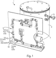
figure 1 shows a perspective view of one embodiment of a refrigeration energy storage system by means of phase change materials (PCM) according to the invention; -
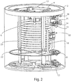
figure 2 shows a perspective view of the body of the system offigure 1 , without the cover, the side wall and the insulating material; -
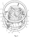
figure 3 shows a perspective top view of the body offigure 2 ; -
figures 4a, 4b and 4c respectively show a first perspective view of the heat exchanger contained inside the body offigure 2 , a second perspective view of said heat exchanger, and a perspective view of a detail of the heat exchanger shown infigure 4a ; -
figure 5 schematically shows an embodiment of an integrative system to prevent the admission of a PCM type fluid within the heat exchanger offigure 2 ;figure 6 shows a block diagram of a first embodiment of a circuit for the integration of the storage system according to the invention with a refrigeration system and with a user; and -
figure 7 shows a block diagram of a second embodiment of a circuit for the integration of the storage system according to the invention with a refrigeration system and with a user. - Making reference now to
figures 1 ,2 ,3 ,4a, 4b and 4c , it is shown an embodiment of a refrigeration, or thermal storage system according to the present invention, generally indicated byreference number 1.Said storage system 1 comprises atank 2 for storage of refrigeration energy, asecondary circuit 3 and a system of showers ornebulizers 4, contained within the volume of thetank 2. - Said
tank 2 can be any insulated, closed, body of appropriate size to kWh to be stored and configured to contain within its volume a PCM type fluid and a secondary fluid, immiscible each other and having different density. In particular, said body is preferably cylindrical. - Physical characteristics of said fluids determine the layering of the same within the volume of the
storage tank 2, with the consequent possibility of withdrawing the secondary fluid, depending on the density value of the latter, from the top or the bottom oftank 2. - In the following, the description of the
storage system 1 will be made with reference to a secondary fluid having a density greater than that of the type PCM fluid, but it should be understood that the elementsdistinguishing system 1 does not vary according to the type of secondary fluid employed. - In the embodiment shown, said PCM type fluid has a solidification temperature preferably equal to 5°C, while said secondary fluid, present within said
tank 2 with a volume rate preferably between 5% and 50%, has a solidification temperature lower than that of said PCM type fluid. - Said
secondary circuit 3 comprises apump 5 for displacement of secondary fluid from inside thetank 2 towards aheat exchanger 6 and from this to the system showers ornebulizers 4. - Said
heat exchanger 6 is preferably comprised of a system of double concentric tubes circular coils and is housed within saidtank 2 and immersed within the PCM type fluid volume. In the embodiment shown, said coil system is comprised by two identical coils connected together to operate in parallel. - Secondary fluid circulates within
inner tube 7 of saidheat exchanger 6, while a primary fluid circulates in counter current within theouter tube 8, entering and exiting in and from a refrigeration system (not shown in these figures) by means of aprimary circuit 9. it is evident that the two fluids may also circulate in co-current. - Said
inner tube 7 of saidheat exchanger 6 is connected, through a system ofpipes 10, to apipe union 11, the latter being connected, through thesecondary circuit 3, to apipe union 12 of thetank 2; said means 12, 3, 11 and 10 allow the flow of the secondary fluid from thestorage tank 2 to theheat exchanger 6. Saidinner tube 7 is also connected, through a system ofpipes 13, to apipe union 14, the latter being connected, by means of acircuit 15, to apipe union 16, connected, through a system ofpipes 17, to the showers ornebulizers system 4; said means 13, 14, 15, 16 and 17 allow the flow of the secondary fluid fromheat exchanger 6 to the showers ornebulizers system 4. - Said
outer pipe 8 is connected, through a system ofpipes 18, to apipe union 19, and, through a system ofpipes 20, to apipe union 21, connected to saidpipe union 19 through theprimary circuit 9; said means 9, 18, 19, 21 and 20 allow the flow of the primary fluid in, and from, theheat exchanger 6. - The showers or
nebulizers system 4 is present in the upper part of thestorage tank 2, for uniform distribution on the surface, and then in the PCM type fluid volume, of droplets of secondary fluid coming from theheat exchanger 6. - Separation means 22 are housed within the volume of the
tank 2, to prevent the release of the type PCM fluid in thesecondary circuit 3. Particularly, said separation means comprise a grid, disposed in such a way that only said secondary fluid is substantially present in correspondence with thenozzle 12. - Said
heat exchanger 6, said showers ornebulizers system 4 and said separation means 22 are supported by abeam system 23. - Operation of the
storage system 1 according to the present invention provides for the withdrawal of the secondary fluid from the bottom of thetank 2 and the circulation of said fluid, thanks to thepump 5, within thesecondary circuit 3, in theheat exchanger 6 and in thecircuit 15, until reaching the system showers ornebulizers system 4. - Secondary fluid absorbs frigories within the
heat exchanger 6, during the storage of refrigerating energy withintank 2, and releases frigories during the release phase of refrigerating energy oftank 2, from, and to, the primary fluid circulating within saidheat exchanger heat 6. Primary fluid is cooled by a refrigeration system during the storage of refrigeration energy withintank 2, while during the release phase of refrigerating energy fromtank 2, before being sent to a final user, it is cooled by the current of the secondary fluid. - Secondary fluid, coming from
heat exchanger 6, is introduced within thetank 2 through the showers ornebulizers system 4, which ensures a uniform distribution of the droplets of the secondary fluid in the PCM type fluid volume. The droplets of secondary fluid evenly run down along the PCM type fluid head optimally transferring refrigeration energy from secondary fluid to the PCM type fluid during the storage of refrigerating energy intank 2 and by the PCM type fluid to the secondary fluid during the release phase of refrigerating energy fromtank 2, so as to obtain, respectively, the solidification of the liquid PCM type fluid and the fusion of the solid PCM type fluid. Also, since the PCM type fluid solidifies creating crystals that are dispersed within the liquid volume, and in intimate contact with the droplets of the secondary fluid, in order to improve the mixing and make sure that the PCM type fluid solidifies by means of a high number of small crystals, secondary fluid can be introduced withintank 2 by means of spays having a suitable speed. - Solidification of PCM type fluid during the storage of refrigerating energy in
tank 2, thus permits storage, instorage tank 2, of refrigerating energy which is then released during the release phase of refrigerating energy fromtank 2, through the fusion of the solid PCM type fluid. - By the solution proposed according to the present invention it is maximized the energy transfer between the refrigeration fluid and the secondary PCM type fluid. The direct contact between said fluids, their different physical characteristics and the showers or nebulizers system guarantee, in fact, an excellent heat exchange efficiency and a rapid transfer of refrigerating energy, with consequent increase of the refrigeration capacity both during the phase of storage of refrigerating energy and during the release phase of refrigerating energy.
- Particularly, showers or nebulizers system, by generating droplets of secondary fluid that evenly run down the PCM type fluid head, allows increasing the contact surface for heat exchange and, due to viscous forces, ensures handling the type PCM fluid, improving energy transportation coefficients.
- Being then the type PCM fluid confined within the tank, it is prevented a movement of the type PCM fluid, under phase change conditions, especially during energy storage, that could generate operational problems such as blockage of pipelines or rupture the pumps. Furthermore, the reduced time of energy storage and release from storage tank allow the use of the storage system according to the present invention to optimize the energy withdrawal period from the main supply or of use of self-produced energy.
- Another embodiment of the present invention provides the application of coatings on the inner surface of the pipes in which circulates the secondary fluid, avoiding the adhesion of the solid PCM type fluid.
- According to a further embodiment of the present invention, the
storage tank 2 can have cubic shape, conical shape, frustum-conical shape, parallelepiped shape, etc. and/or composite shape obtained by the union of one or more of the mentioned above shapes. According to another embodiment of the present invention, structures having a rough surface, such as filaments, grids or nets, immersed within the PCM type fluid volume, in order to promote and manage the formation of first PCM type fluid crystals during storage of refrigeration energy. - A further embodiment of the present invention involves the use of ultrasound systems, or similar systems, in order to facilitate the formation of first PCM type fluid crystals during the storage of refrigeration energy by
tank 2 and thus reduce the eventual supercooling effect of PCM type fluid. - Another embodiment of the present invention involves the use of only the PCM type fluids and of the primary fluid, thereby avoiding the use of a secondary circuit. In this configuration, it is the primary fluid which, descending through the PCM type fluid head, releases, during the storage phase, and absorbs, during the release phase, the refrigerating energy.
- According to a further example which does not fall under the present invention, the
heat exchanger 6 may be located outside thestorage tank 2, in order to increase the PCM type fluid volume the that can be contained within thetank 2, and/or different technologies may be used compared to the double concentric pipes coils system, such as rube bundle exchanger, plate exchangers, horizontal or vertical exchangers, shirt exchangers. - Another embodiment of the present invention provides the use of separation means different from the grid, such as a selective membrane to only the secondary fluid, placed on the surface or within the secondary fluid volume.
- According to another embodiment of the present invention (shown in
figure 5 ), to prevent the admission of PCM type fluid in thesecondary circuit 3 following the operation of thepump 5, they may be used, instead of thesystems 24 lengthening the path of secondary fluid to enter into apump 5suction duct 25, connected directly or through theunion pipe 12 to thesecondary circuit 3. Particularly, in the embodiment shown, thesuction duct 25 provides avertical extension 26, protected by aconduit 27 coaxial thereto and of greater diameter, closed from the upper side and with apossible valve 28 which, if necessary, allows purging by suction. Said optional device can be usefully employed in the case in which density of the liquid PCM type fluid is less than that of the secondary fluid while the density of PCM type solid PCM type fluid is higher than that of said secondary fluid. In this situation,separation devices 22 may permit the passage of solid particles of small diameter of PCM type fluid. The presence of saiddevices 24 can ensure an additional level of separation, avoiding that the particles of solid PCM type fluid deposited on the bottom occlude thesuction duct 25. - Another embodiment of the present invention provides the use of movable, continuous and discrete showers or nebulizers systems.
- Referring now to
figure 6 , there is shown a first embodiment of acircuit 29 for the integration of thecold storage system 1 according to the present invention with arefrigerator group 30 and auser 31, arranged functionally in parallel each other. - Said
circuit 29 comprises a three-way diverting valve 32, in a 0% or 100% mode, a three-way mixing valve 33, apump 34 for moving the primary fluid through thecircuit valve 29 and a three-way diverting valve 35. - In the following, the description of the
circuit 29 will be made with reference to aheat exchanger 6 in which the primary fluid and the secondary fluid circulate in counter current, but it should be understood that the elements distinguishing the circuit does not vary if the two fluids circulate in co-current. - Said
valve 32 allows, during the storage of refrigerating energy, the flow of the primary fluid, cooled by therefrigerator group 30, in theheat exchanger 6, while, during the release phase of refrigerating energy, allows the flow of the primary fluid, cooled by the secondary fluid circulating in theheat exchanger 6, towards theuser 31. - If during the storage of refrigerating energy it is provided the transfer of frigories from the primary fluid either to the
user 31 and to the secondary fluid, the mixingvalve 33 allows the mixing of the primary fluid coming from theheat exchanger 6 with the primary fluid coming 31 from the user, by sending the mixed fluids to the intake ofpump 34 and then in therefrigerator group 30. If, instead, during the storage of refrigerating energy it is provided only the transfer of refrigeration from the cooled primary fluid to the secondary fluid, said mixingvalve 33 allows only the circulation of the primary fluid coming from theheat exchanger 6 to the intake ofpump 34 and then in therefrigerator group 30. - Moreover, during the release phase of refrigerating energy, said
valve 33 allows only the circulation of the primary fluid coming from theuser 31 to the intake of thepump 34. - Said diverting
valve 35 enables, during the storage of refrigerating energy, the flow of the primary fluid leaving theheat exchanger 6 through thevalve 33 and then through thepump 34, toward therefrigeration group 30, while, during the phase of release of refrigerating energy, allows the flow of the primary fluid coming from theuser 31 through thevalve 33, and then through thepump 34, toward therefrigeration group 30 and/or to theheat exchanger 6. - The operation of the
circuit 29 according to the present invention provides that, during the storage of refrigerating energy, the primary fluid cooled by therefrigeration group 30 can refrigerate the secondary fluid circulating in theheat exchanger 6 and/or provide the refrigeration power required by theuser 31. However, during the release phase of refrigerating energy, the refrigerating power required by theuser 31 can be provided by the primary fluid cooled by therefrigeration unit 30 and/or the primary fluid cooled by the secondary fluid circulating in theheat exchanger 6. - Therefore, the integration proposed according to the present invention of the cold storage system with a refrigeration system and a user allows to optimize the withdrawal period of the energy from the mains, reducing load peaks (peak shaving), or the use of self-produced energy.
- In fact, frigories, or part of frigories, required by the user during the peak hours may be supplied from the cold storage tank, previously loaded during the non-peak time period, with a consequent reduction of the peak power and increase the refrigerating machines COP. Moreover, the presence of the cold storage tank in the
circuit 29, operating to support the refrigerating machine, allows to reduce the power of the latter, with a consequent reduction of production costs, and of the price, of the refrigerating machine. By the application of a suitable management system of the energy flows, it is possible to operate the refrigerating machine at constant, or nearly constant, power, and at the optimum operation point (greater COP), by providing the peaks of refrigeration energy required by the user to the storage system. - Making reference to
figure 7 , there is shown a second embodiment of thecircuit 29 for the integration of thecold storage system 1 according to the present invention with arefrigeration group 30 and auser 31, functionally arranged both in parallel and in series. Saidcircuit 29 comprises twopumps way valves - Particularly, keeping
closed valves valves valves - Keeping instead closed
valves valves valves - Keeping closed
valves valves closed valves valves refrigeration group 30 to theheat exchanger 6 to theuser 31, and vice versa. - The present invention has been described for illustrative but not limitative purposes, according to its preferred embodiments, but it is to be understood that variations and/or modifications may be made by those skilled in the art without departing from the relative scope of protection, as defined by the appended claims.
Claims (12)
- Refrigeration or thermal energy storage system (1) for storing refrigeration or thermal energy to be released when required by users, comprising
a body (2), closed and insulated, said body (2) being configured to contain two fluids within its volume, respectively a Phase Change Material (PCM) type fluid and a secondary fluid, said two fluids being immiscible each other and having different density, so as to be stratified within the volume of said body (2);
withdrawal means (3) configured to draw said secondary fluid from said body (2), and to convey the same inside a heat exchanger (6), said heat exchanger (6) being configured to exchange frigories, or calories, with said secondary fluid; and
distribution means (4) configured to draw said secondary fluid from said heat exchanger (6), and to distribute, within said body (2), said secondary fluid into said PCM type fluid, so as that said secondary fluid exchanges with said PCM type fluid frigories, or calories, absorbed in said heat exchanger (6),
said secondary fluid having a solidification temperature substantially lower than that of said PCM type fluid,
said heat exchanger (6) comprising a first pipe (7), connected at its ends respectively to said withdrawal means (3) and to said distribution means (4), for the circulation of said secondary fluid,
said energy storage system (1) being characterized in that
said heat exchanger (6) is housed inside said body (2), and being exchange frigories, or calories, between said secondary fluid and a primary fluid,
and in that a second pipe (8), concentric with respect to said first pipe, is configured to be connected to a circuit (9) external to said body (2), for the circulation of said primary fluid. - System (1) according to the precedent claim, characterized in that said withdrawal means (3) are placed at least partially in the upper, or lower, part of said body (2), depending on the density value of said secondary fluid, and in that said distribution means (4) are placed at least partially in the upper, or lower, part of said body (2), in an opposite manner to the position of said withdrawal means (3).
- System (1) according to one of the precedent claims, characterized in that said volume of said body (2) comprises separation means (22) to prevent the inlet of said PCM type fluid into said withdrawal means (3).
- System (1) according to claim 3, characterized in that said separation means (22) comprise a grid, or a membrane, impermeable to said PCM type fluid and placed so as that only said secondary fluid is substantially present in correspondence of said withdrawal means (3).
- System (1) according to claim 3, characterized in that said separation means comprise an "S" path to prevent the inlet of said PCM type fluid into said withdrawal means (3).
- System (1) according to one of the precedent claims, characterized in that said withdrawal means (3) comprises a pump (5) to convey said secondary fluid into said heat exchanger (6).
- System (1) according to one of the precedent claims, characterized in that said distribution means (4) comprise shower nozzles and/or nebulizers and/or hydraulic vortexes to distribute, inside said body (2), said secondary fluid into said PCM type fluid.
- System (1) according to one of the precedent claims, characterized in that said secondary fluid is present within said body (2) with a percentage in volume preferably between 5% and 50%.
- System (1) according to one of the precedent claims, characterized in that said secondary fluid has a density greater than that of said PCM type fluid.
- System (1) according to one of the precedent claims, characterized in that said secondary fluid is water.
- Storage plant (29) to store refrigeration or thermal energy to be released when required, comprising
a refrigeration or thermal energy storage system (1) according to one of the claims 1-10;
a refrigeration or thermal unit (30) connected to said heat exchanger (6), and configured to release frigories, or calories, to a primary fluid when said system (29) is in a refrigeration, or thermal, energy storage configuration, so as that said frigories, o calories, are later released by said primary fluid to said secondary fluid in said heat exchanger (6), and further later exchanged between said secondary fluid and said PCM type fluid inside said body (2);
users (31), connected to said heat exchanger (6) so as that, when said system (29) is in a energy release configuration, said PCM type fluid exchanges frigories, or calories, with said secondary fluid inside said body (2), and later said secondary fluid releases said frigories, or calories, to said primary fluid in said heat exchanger (6), and further later said primary fluid releases said frigories, or calories, to said users (31); and
a valves and pumps system for the circulation of said primary fluid so as that said system (29) can pass from a refrigeration, or thermal, energy storage configuration to a energy release configuration, and vice versa. - Storage plant (29) according to claim 11, characterized in that said refrigeration, or thermal, unit (30) is connected to said heat exchanger (6) and to said users (31), so as that, said refrigeration, or thermal, unit (30) exchanges frigories, or calories, with said primary fluid, and later said primary fluid exchanges frigories, or calories, with said secondary fluid in said heat exchanger (6) and with said users (31), and in that said valves and pumps system allows to operate in a refrigeration, or thermal, energy storage mode releasing frigories, or calories, to said secondary fluid in said heat exchanger (6) or to said users (31) or to both of them at the same time, and in a refrigeration, or thermal, energy release mode with release of frigories, or calories, to said primary fluid by said secondary fluid in said heat exchanger (6) or by part of said refrigeration, or thermal, unit (30) or by both of them at the same time.
Applications Claiming Priority (2)
| Application Number | Priority Date | Filing Date | Title |
|---|---|---|---|
| ITRM20140500 | 2014-09-04 | ||
| PCT/IT2015/000209 WO2016035105A1 (en) | 2014-09-04 | 2015-09-02 | Refrigeration, or thermal, energy storage system by phase change materials |
Publications (2)
| Publication Number | Publication Date |
|---|---|
| EP3189294A1 EP3189294A1 (en) | 2017-07-12 |
| EP3189294B1 true EP3189294B1 (en) | 2020-06-24 |
Family
ID=51799247
Family Applications (1)
| Application Number | Title | Priority Date | Filing Date |
|---|---|---|---|
| EP15791774.1A Active EP3189294B1 (en) | 2014-09-04 | 2015-09-02 | Refrigeration or thermal energy storage system by phase change materials |
Country Status (5)
| Country | Link |
|---|---|
| US (1) | US20170248377A1 (en) |
| EP (1) | EP3189294B1 (en) |
| CN (1) | CN107110614A (en) |
| AU (1) | AU2015310472A1 (en) |
| WO (1) | WO2016035105A1 (en) |
Families Citing this family (7)
| Publication number | Priority date | Publication date | Assignee | Title |
|---|---|---|---|---|
| JP6720752B2 (en) * | 2016-07-25 | 2020-07-08 | 富士通株式会社 | Immersion cooling device, immersion cooling system, and method of controlling immersion cooling device |
| EP3379191B1 (en) * | 2017-03-20 | 2020-03-11 | Lumenion GmbH | Thermal storage device and method for operating a thermal storage device |
| KR20200128592A (en) * | 2018-04-04 | 2020-11-13 | 액티브 에너지 시스템즈 | Heat exchange system and method for freezing phase change material |
| CN112728789B (en) * | 2021-01-19 | 2022-10-21 | 太原理工大学 | Phase-change heat storage and exchange integrated water tank |
| CN112944203B (en) * | 2021-03-22 | 2022-11-01 | 中海石油气电集团有限责任公司 | Heat preservation cold insulation circulation system based on phase change heat insulation material |
| US11680754B2 (en) * | 2021-04-09 | 2023-06-20 | Trane International Inc. | Systems and methods for thermal storage solid phase formation removal |
| CN116853508B (en) * | 2023-09-04 | 2023-11-14 | 中国航空工业集团公司金城南京机电液压工程研究中心 | Aircraft spray cooling control method and device |
Family Cites Families (7)
| Publication number | Priority date | Publication date | Assignee | Title |
|---|---|---|---|---|
| US2996894A (en) * | 1956-12-13 | 1961-08-22 | Gen Electric | Method and apparatus for the recovery of latent heat of fusion |
| DE2607168C3 (en) * | 1976-02-21 | 1981-04-09 | Deutsche Forschungs- und Versuchsanstalt für Luft- und Raumfahrt e.V., 5300 Bonn | Device for exchanging heat |
| US4109702A (en) * | 1976-08-06 | 1978-08-29 | Greene Norman Donald | Energy storage and retrieval as heat |
| CH639477A5 (en) * | 1979-04-18 | 1983-11-15 | Sulzer Ag | METHOD FOR EXCHANGING HEAT IN A LATENT HEAT STORAGE AND DEVICE FOR IMPLEMENTING THE METHOD. |
| US4696338A (en) * | 1982-06-01 | 1987-09-29 | Thermal Energy Stroage, Inc. | Latent heat storage and transfer system and method |
| AU2008281327A1 (en) * | 2007-08-01 | 2009-02-05 | Albert Massey Trihey | Fluid heater |
| CN103291408A (en) * | 2012-02-27 | 2013-09-11 | 上海索菲玛汽车滤清器有限公司 | Distribution device for liquid lubricant |
-
2015
- 2015-09-02 WO PCT/IT2015/000209 patent/WO2016035105A1/en active Application Filing
- 2015-09-02 EP EP15791774.1A patent/EP3189294B1/en active Active
- 2015-09-02 AU AU2015310472A patent/AU2015310472A1/en not_active Abandoned
- 2015-09-02 US US15/508,044 patent/US20170248377A1/en not_active Abandoned
- 2015-09-02 CN CN201580056051.9A patent/CN107110614A/en active Pending
Non-Patent Citations (1)
| Title |
|---|
| None * |
Also Published As
| Publication number | Publication date |
|---|---|
| US20170248377A1 (en) | 2017-08-31 |
| AU2015310472A1 (en) | 2017-04-20 |
| CN107110614A (en) | 2017-08-29 |
| EP3189294A1 (en) | 2017-07-12 |
| WO2016035105A1 (en) | 2016-03-10 |
Similar Documents
| Publication | Publication Date | Title |
|---|---|---|
| EP3189294B1 (en) | Refrigeration or thermal energy storage system by phase change materials | |
| US10088243B2 (en) | Thermal energy battery with enhanced heat exchange capability and modularity | |
| US4131158A (en) | Storage arrangement for thermal energy | |
| US7942018B2 (en) | Apparatus for cooling or heating thermal storage using microencapsulated phase change material slurries | |
| US10267570B2 (en) | Coolant heat exchanger having a scraper for each heat exchange interface surface | |
| US20130105106A1 (en) | Systems And Methods For Thermal Energy Storage | |
| US20110083827A1 (en) | Cooling system with integral thermal energy storage | |
| Chen et al. | Experimental investigation on PCM cold storage integrated with ejector cooling system | |
| CN105640164A (en) | Ice storage cold fresh display cabinet | |
| CN104019686A (en) | Efficient phase change cold storage heat exchange tube | |
| JP5854613B2 (en) | Latent heat storage hot water storage tank and water heater | |
| JP2008020177A (en) | Heat storage system | |
| CN101846420A (en) | Refrigeration equipment | |
| CN101354223A (en) | Energy-saving apparatus | |
| CN111351165B (en) | Compartment fractal ice storage tank | |
| CN203083413U (en) | Energy storage device and air conditioner device | |
| CN105953337B (en) | Ice thermal storage air conditioning unit and its control method | |
| CN201697408U (en) | Refrigerating equipment | |
| US6158236A (en) | Refrigeration capacity accumulator | |
| CN113933336A (en) | Phase change material testing assembly, testing system and control method | |
| CN104582921A (en) | Device and method for changing the temperature of objects | |
| CN208269700U (en) | Unitized exchanger | |
| CN217005463U (en) | Heat pipe system and refrigeration equipment | |
| CN211476185U (en) | Ice storage water tank based on flat heat pipe | |
| CN209944833U (en) | Household detachable refrigerator assembly and refrigerator |
Legal Events
| Date | Code | Title | Description |
|---|---|---|---|
| STAA | Information on the status of an ep patent application or granted ep patent |
Free format text: STATUS: THE INTERNATIONAL PUBLICATION HAS BEEN MADE |
|
| PUAI | Public reference made under article 153(3) epc to a published international application that has entered the european phase |
Free format text: ORIGINAL CODE: 0009012 |
|
| STAA | Information on the status of an ep patent application or granted ep patent |
Free format text: STATUS: REQUEST FOR EXAMINATION WAS MADE |
|
| 17P | Request for examination filed |
Effective date: 20170330 |
|
| AK | Designated contracting states |
Kind code of ref document: A1 Designated state(s): AL AT BE BG CH CY CZ DE DK EE ES FI FR GB GR HR HU IE IS IT LI LT LU LV MC MK MT NL NO PL PT RO RS SE SI SK SM TR |
|
| AX | Request for extension of the european patent |
Extension state: BA ME |
|
| DAX | Request for extension of the european patent (deleted) | ||
| GRAP | Despatch of communication of intention to grant a patent |
Free format text: ORIGINAL CODE: EPIDOSNIGR1 |
|
| STAA | Information on the status of an ep patent application or granted ep patent |
Free format text: STATUS: GRANT OF PATENT IS INTENDED |
|
| RIC1 | Information provided on ipc code assigned before grant |
Ipc: F28F 9/013 20060101ALI20191212BHEP Ipc: F28D 7/14 20060101ALI20191212BHEP Ipc: F24F 5/00 20060101ALI20191212BHEP Ipc: F28D 1/04 20060101ALI20191212BHEP Ipc: F25B 25/00 20060101ALI20191212BHEP Ipc: F28D 20/02 20060101AFI20191212BHEP |
|
| INTG | Intention to grant announced |
Effective date: 20200113 |
|
| GRAS | Grant fee paid |
Free format text: ORIGINAL CODE: EPIDOSNIGR3 |
|
| GRAA | (expected) grant |
Free format text: ORIGINAL CODE: 0009210 |
|
| STAA | Information on the status of an ep patent application or granted ep patent |
Free format text: STATUS: THE PATENT HAS BEEN GRANTED |
|
| AK | Designated contracting states |
Kind code of ref document: B1 Designated state(s): AL AT BE BG CH CY CZ DE DK EE ES FI FR GB GR HR HU IE IS IT LI LT LU LV MC MK MT NL NO PL PT RO RS SE SI SK SM TR |
|
| REG | Reference to a national code |
Ref country code: GB Ref legal event code: FG4D |
|
| REG | Reference to a national code |
Ref country code: CH Ref legal event code: EP |
|
| REG | Reference to a national code |
Ref country code: AT Ref legal event code: REF Ref document number: 1284308 Country of ref document: AT Kind code of ref document: T Effective date: 20200715 |
|
| REG | Reference to a national code |
Ref country code: DE Ref legal event code: R096 Ref document number: 602015054775 Country of ref document: DE |
|
| REG | Reference to a national code |
Ref country code: IE Ref legal event code: FG4D |
|
| PG25 | Lapsed in a contracting state [announced via postgrant information from national office to epo] |
Ref country code: LT Free format text: LAPSE BECAUSE OF FAILURE TO SUBMIT A TRANSLATION OF THE DESCRIPTION OR TO PAY THE FEE WITHIN THE PRESCRIBED TIME-LIMIT Effective date: 20200624 Ref country code: GR Free format text: LAPSE BECAUSE OF FAILURE TO SUBMIT A TRANSLATION OF THE DESCRIPTION OR TO PAY THE FEE WITHIN THE PRESCRIBED TIME-LIMIT Effective date: 20200925 Ref country code: NO Free format text: LAPSE BECAUSE OF FAILURE TO SUBMIT A TRANSLATION OF THE DESCRIPTION OR TO PAY THE FEE WITHIN THE PRESCRIBED TIME-LIMIT Effective date: 20200924 Ref country code: SE Free format text: LAPSE BECAUSE OF FAILURE TO SUBMIT A TRANSLATION OF THE DESCRIPTION OR TO PAY THE FEE WITHIN THE PRESCRIBED TIME-LIMIT Effective date: 20200624 Ref country code: FI Free format text: LAPSE BECAUSE OF FAILURE TO SUBMIT A TRANSLATION OF THE DESCRIPTION OR TO PAY THE FEE WITHIN THE PRESCRIBED TIME-LIMIT Effective date: 20200624 |
|
| REG | Reference to a national code |
Ref country code: LT Ref legal event code: MG4D |
|
| PG25 | Lapsed in a contracting state [announced via postgrant information from national office to epo] |
Ref country code: HR Free format text: LAPSE BECAUSE OF FAILURE TO SUBMIT A TRANSLATION OF THE DESCRIPTION OR TO PAY THE FEE WITHIN THE PRESCRIBED TIME-LIMIT Effective date: 20200624 Ref country code: RS Free format text: LAPSE BECAUSE OF FAILURE TO SUBMIT A TRANSLATION OF THE DESCRIPTION OR TO PAY THE FEE WITHIN THE PRESCRIBED TIME-LIMIT Effective date: 20200624 Ref country code: LV Free format text: LAPSE BECAUSE OF FAILURE TO SUBMIT A TRANSLATION OF THE DESCRIPTION OR TO PAY THE FEE WITHIN THE PRESCRIBED TIME-LIMIT Effective date: 20200624 Ref country code: BG Free format text: LAPSE BECAUSE OF FAILURE TO SUBMIT A TRANSLATION OF THE DESCRIPTION OR TO PAY THE FEE WITHIN THE PRESCRIBED TIME-LIMIT Effective date: 20200924 |
|
| REG | Reference to a national code |
Ref country code: NL Ref legal event code: MP Effective date: 20200624 |
|
| REG | Reference to a national code |
Ref country code: AT Ref legal event code: MK05 Ref document number: 1284308 Country of ref document: AT Kind code of ref document: T Effective date: 20200624 |
|
| PG25 | Lapsed in a contracting state [announced via postgrant information from national office to epo] |
Ref country code: AL Free format text: LAPSE BECAUSE OF FAILURE TO SUBMIT A TRANSLATION OF THE DESCRIPTION OR TO PAY THE FEE WITHIN THE PRESCRIBED TIME-LIMIT Effective date: 20200624 Ref country code: NL Free format text: LAPSE BECAUSE OF FAILURE TO SUBMIT A TRANSLATION OF THE DESCRIPTION OR TO PAY THE FEE WITHIN THE PRESCRIBED TIME-LIMIT Effective date: 20200624 |
|
| PG25 | Lapsed in a contracting state [announced via postgrant information from national office to epo] |
Ref country code: PT Free format text: LAPSE BECAUSE OF FAILURE TO SUBMIT A TRANSLATION OF THE DESCRIPTION OR TO PAY THE FEE WITHIN THE PRESCRIBED TIME-LIMIT Effective date: 20201026 Ref country code: ES Free format text: LAPSE BECAUSE OF FAILURE TO SUBMIT A TRANSLATION OF THE DESCRIPTION OR TO PAY THE FEE WITHIN THE PRESCRIBED TIME-LIMIT Effective date: 20200624 Ref country code: CZ Free format text: LAPSE BECAUSE OF FAILURE TO SUBMIT A TRANSLATION OF THE DESCRIPTION OR TO PAY THE FEE WITHIN THE PRESCRIBED TIME-LIMIT Effective date: 20200624 Ref country code: RO Free format text: LAPSE BECAUSE OF FAILURE TO SUBMIT A TRANSLATION OF THE DESCRIPTION OR TO PAY THE FEE WITHIN THE PRESCRIBED TIME-LIMIT Effective date: 20200624 Ref country code: EE Free format text: LAPSE BECAUSE OF FAILURE TO SUBMIT A TRANSLATION OF THE DESCRIPTION OR TO PAY THE FEE WITHIN THE PRESCRIBED TIME-LIMIT Effective date: 20200624 Ref country code: AT Free format text: LAPSE BECAUSE OF FAILURE TO SUBMIT A TRANSLATION OF THE DESCRIPTION OR TO PAY THE FEE WITHIN THE PRESCRIBED TIME-LIMIT Effective date: 20200624 Ref country code: SM Free format text: LAPSE BECAUSE OF FAILURE TO SUBMIT A TRANSLATION OF THE DESCRIPTION OR TO PAY THE FEE WITHIN THE PRESCRIBED TIME-LIMIT Effective date: 20200624 |
|
| PGFP | Annual fee paid to national office [announced via postgrant information from national office to epo] |
Ref country code: IE Payment date: 20201229 Year of fee payment: 6 |
|
| PG25 | Lapsed in a contracting state [announced via postgrant information from national office to epo] |
Ref country code: PL Free format text: LAPSE BECAUSE OF FAILURE TO SUBMIT A TRANSLATION OF THE DESCRIPTION OR TO PAY THE FEE WITHIN THE PRESCRIBED TIME-LIMIT Effective date: 20200624 Ref country code: SK Free format text: LAPSE BECAUSE OF FAILURE TO SUBMIT A TRANSLATION OF THE DESCRIPTION OR TO PAY THE FEE WITHIN THE PRESCRIBED TIME-LIMIT Effective date: 20200624 Ref country code: IS Free format text: LAPSE BECAUSE OF FAILURE TO SUBMIT A TRANSLATION OF THE DESCRIPTION OR TO PAY THE FEE WITHIN THE PRESCRIBED TIME-LIMIT Effective date: 20201024 |
|
| REG | Reference to a national code |
Ref country code: DE Ref legal event code: R097 Ref document number: 602015054775 Country of ref document: DE |
|
| REG | Reference to a national code |
Ref country code: DE Ref legal event code: R119 Ref document number: 602015054775 Country of ref document: DE |
|
| PG25 | Lapsed in a contracting state [announced via postgrant information from national office to epo] |
Ref country code: DK Free format text: LAPSE BECAUSE OF FAILURE TO SUBMIT A TRANSLATION OF THE DESCRIPTION OR TO PAY THE FEE WITHIN THE PRESCRIBED TIME-LIMIT Effective date: 20200624 Ref country code: MC Free format text: LAPSE BECAUSE OF FAILURE TO SUBMIT A TRANSLATION OF THE DESCRIPTION OR TO PAY THE FEE WITHIN THE PRESCRIBED TIME-LIMIT Effective date: 20200624 |
|
| PLBE | No opposition filed within time limit |
Free format text: ORIGINAL CODE: 0009261 |
|
| REG | Reference to a national code |
Ref country code: CH Ref legal event code: PL |
|
| STAA | Information on the status of an ep patent application or granted ep patent |
Free format text: STATUS: NO OPPOSITION FILED WITHIN TIME LIMIT |
|
| GBPC | Gb: european patent ceased through non-payment of renewal fee |
Effective date: 20200924 |
|
| VS25 | Lapsed in a validation state [announced via postgrant information from nat. office to epo] |
Ref country code: MA Free format text: LAPSE BECAUSE OF FAILURE TO SUBMIT A TRANSLATION OF THE DESCRIPTION OR TO PAY THE FEE WITHIN THE PRESCRIBED TIME-LIMIT Effective date: 20200624 |
|
| 26N | No opposition filed |
Effective date: 20210325 |
|
| REG | Reference to a national code |
Ref country code: BE Ref legal event code: MM Effective date: 20200930 |
|
| PG25 | Lapsed in a contracting state [announced via postgrant information from national office to epo] |
Ref country code: LU Free format text: LAPSE BECAUSE OF NON-PAYMENT OF DUE FEES Effective date: 20200902 |
|
| PG25 | Lapsed in a contracting state [announced via postgrant information from national office to epo] |
Ref country code: DE Free format text: LAPSE BECAUSE OF NON-PAYMENT OF DUE FEES Effective date: 20210401 Ref country code: FR Free format text: LAPSE BECAUSE OF NON-PAYMENT OF DUE FEES Effective date: 20200930 |
|
| PG25 | Lapsed in a contracting state [announced via postgrant information from national office to epo] |
Ref country code: SI Free format text: LAPSE BECAUSE OF FAILURE TO SUBMIT A TRANSLATION OF THE DESCRIPTION OR TO PAY THE FEE WITHIN THE PRESCRIBED TIME-LIMIT Effective date: 20200624 Ref country code: LI Free format text: LAPSE BECAUSE OF NON-PAYMENT OF DUE FEES Effective date: 20200930 Ref country code: GB Free format text: LAPSE BECAUSE OF NON-PAYMENT OF DUE FEES Effective date: 20200924 Ref country code: CH Free format text: LAPSE BECAUSE OF NON-PAYMENT OF DUE FEES Effective date: 20200930 Ref country code: BE Free format text: LAPSE BECAUSE OF NON-PAYMENT OF DUE FEES Effective date: 20200930 |
|
| PG25 | Lapsed in a contracting state [announced via postgrant information from national office to epo] |
Ref country code: TR Free format text: LAPSE BECAUSE OF FAILURE TO SUBMIT A TRANSLATION OF THE DESCRIPTION OR TO PAY THE FEE WITHIN THE PRESCRIBED TIME-LIMIT Effective date: 20200624 Ref country code: MT Free format text: LAPSE BECAUSE OF FAILURE TO SUBMIT A TRANSLATION OF THE DESCRIPTION OR TO PAY THE FEE WITHIN THE PRESCRIBED TIME-LIMIT Effective date: 20200624 Ref country code: CY Free format text: LAPSE BECAUSE OF FAILURE TO SUBMIT A TRANSLATION OF THE DESCRIPTION OR TO PAY THE FEE WITHIN THE PRESCRIBED TIME-LIMIT Effective date: 20200624 |
|
| PG25 | Lapsed in a contracting state [announced via postgrant information from national office to epo] |
Ref country code: MK Free format text: LAPSE BECAUSE OF FAILURE TO SUBMIT A TRANSLATION OF THE DESCRIPTION OR TO PAY THE FEE WITHIN THE PRESCRIBED TIME-LIMIT Effective date: 20200624 |
|
| PG25 | Lapsed in a contracting state [announced via postgrant information from national office to epo] |
Ref country code: IE Free format text: LAPSE BECAUSE OF NON-PAYMENT OF DUE FEES Effective date: 20210902 |
|
| PGFP | Annual fee paid to national office [announced via postgrant information from national office to epo] |
Ref country code: IT Payment date: 20230331 Year of fee payment: 8 |