EP3189276B1 - Gas turbine with combustor arrangement including flow control vanes - Google Patents
Gas turbine with combustor arrangement including flow control vanes Download PDFInfo
- Publication number
- EP3189276B1 EP3189276B1 EP14771705.2A EP14771705A EP3189276B1 EP 3189276 B1 EP3189276 B1 EP 3189276B1 EP 14771705 A EP14771705 A EP 14771705A EP 3189276 B1 EP3189276 B1 EP 3189276B1
- Authority
- EP
- European Patent Office
- Prior art keywords
- guide vanes
- combustor
- flow
- inner cylinder
- circumferentially
- Prior art date
- Legal status (The legal status is an assumption and is not a legal conclusion. Google has not performed a legal analysis and makes no representation as to the accuracy of the status listed.)
- Not-in-force
Links
Images


Classifications
-
- F—MECHANICAL ENGINEERING; LIGHTING; HEATING; WEAPONS; BLASTING
- F23—COMBUSTION APPARATUS; COMBUSTION PROCESSES
- F23R—GENERATING COMBUSTION PRODUCTS OF HIGH PRESSURE OR HIGH VELOCITY, e.g. GAS-TURBINE COMBUSTION CHAMBERS
- F23R3/00—Continuous combustion chambers using liquid or gaseous fuel
- F23R3/42—Continuous combustion chambers using liquid or gaseous fuel characterised by the arrangement or form of the flame tubes or combustion chambers
- F23R3/425—Combustion chambers comprising a tangential or helicoidal arrangement of the flame tubes
-
- F—MECHANICAL ENGINEERING; LIGHTING; HEATING; WEAPONS; BLASTING
- F23—COMBUSTION APPARATUS; COMBUSTION PROCESSES
- F23R—GENERATING COMBUSTION PRODUCTS OF HIGH PRESSURE OR HIGH VELOCITY, e.g. GAS-TURBINE COMBUSTION CHAMBERS
- F23R3/00—Continuous combustion chambers using liquid or gaseous fuel
- F23R3/02—Continuous combustion chambers using liquid or gaseous fuel characterised by the air-flow or gas-flow configuration
- F23R3/04—Air inlet arrangements
-
- F—MECHANICAL ENGINEERING; LIGHTING; HEATING; WEAPONS; BLASTING
- F23—COMBUSTION APPARATUS; COMBUSTION PROCESSES
- F23R—GENERATING COMBUSTION PRODUCTS OF HIGH PRESSURE OR HIGH VELOCITY, e.g. GAS-TURBINE COMBUSTION CHAMBERS
- F23R3/00—Continuous combustion chambers using liquid or gaseous fuel
- F23R3/42—Continuous combustion chambers using liquid or gaseous fuel characterised by the arrangement or form of the flame tubes or combustion chambers
- F23R3/54—Reverse-flow combustion chambers
-
- F—MECHANICAL ENGINEERING; LIGHTING; HEATING; WEAPONS; BLASTING
- F23—COMBUSTION APPARATUS; COMBUSTION PROCESSES
- F23R—GENERATING COMBUSTION PRODUCTS OF HIGH PRESSURE OR HIGH VELOCITY, e.g. GAS-TURBINE COMBUSTION CHAMBERS
- F23R2900/00—Special features of, or arrangements for continuous combustion chambers; Combustion processes therefor
- F23R2900/03043—Convection cooled combustion chamber walls with means for guiding the cooling air flow
-
- F—MECHANICAL ENGINEERING; LIGHTING; HEATING; WEAPONS; BLASTING
- F23—COMBUSTION APPARATUS; COMBUSTION PROCESSES
- F23R—GENERATING COMBUSTION PRODUCTS OF HIGH PRESSURE OR HIGH VELOCITY, e.g. GAS-TURBINE COMBUSTION CHAMBERS
- F23R2900/00—Special features of, or arrangements for continuous combustion chambers; Combustion processes therefor
- F23R2900/03045—Convection cooled combustion chamber walls provided with turbolators or means for creating turbulences to increase cooling
Definitions
- the present invention relates in general to turbine engines and, more particularly, to a combustor arrangement for producing a hot working gas that is conveyed from a combustor to turbine blades in a gas turbine engine.
- a gas turbine engine typically includes a compressor section, a combustion section including a plurality of combustors, and a turbine section. Ambient air is compressed in the compressor section and conveyed to the combustors in the combustion section.
- the combustors combine the compressed air with a fuel and ignite the mixture creating combustion products defining hot working gases that flow in a turbulent manner and at a high velocity.
- the working gases are routed to the turbine section via a plurality of gas passages, conventionally referred to as transition ducts.
- Within the turbine section are rows of stationary vane assemblies and rotating blade assemblies.
- the rotating blade assemblies are coupled to a turbine rotor. As the working gases expand through the turbine section, the working gases cause the blade assemblies, and therefore the turbine rotor, to rotate.
- the turbine rotor may be linked to an electric generator, wherein the rotation of the turbine rotor can be used to produce electricity in the generator.
- the compressed air is routed between a flow sleeve and an inner cylinder of a respective combustor to provide the air for combustion in a combustion zone surrounded by the inner cylinder.
- the gas passages each include an inlet positioned adjacent to a respective combustor, and each gas passage routes a flow of working gases into the turbine section through a turbine inlet structure associated with a first row of turbine vanes.
- JP 2000 146186 A discloses that high pressure air introduced from an air compressor is introduced from a diffuser into a compartment, fed through a gap between a tail cylinder 4 and a tail cylinder flow sleeve 5 installed on an outer periphery of the cylinder 4, and then passed through a gap between a liner and a liner flow sleeve disposed on a concentric circle of the outer periphery of the liner.
- a can annular gas turbine engine comprising a combustor arrangement
- the gas turbine engine has a gas delivery structure for delivering gases from a plurality of combustors to an annular chamber that extends circumferentially and is oriented concentric to a gas turbine engine axis for delivering the gas flow to a first row of blades.
- a gas flow path is formed by a duct arrangement between a respective combustor and the annular chamber for conveying gases in a downstream direction from each combustor to the first row of turbine blades.
- the combustor arrangement comprises a combustor having an inner cylinder surrounding a combustion zone of the combustor.
- the inner cylinder defines a longitudinal axis of the combustor that is oriented in a radially inward and circumferentially angled direction toward the annular chamber.
- a cone section is provided having an inlet end receiving the gas flow from the inner cylinder, wherein the cone section defines a decreasing flow area in the downstream direction.
- a flow sleeve surrounds the inner cylinder, and an annular space is defined between the inner cylinder and the flow sleeve and defines an air flow path having an annular air inlet defined along the inner cylinder radially inward of a junction between the inner cylinder and the cone section.
- a plurality of guide vanes are located in circumferentially spaced relation to each other in the annular space, spanning between the flow sleeve and the inner cylinder.
- the guide vanes each have a length dimension defined between a radially inner leading edge and a radially outer trailing edge, wherein the leading edges of the guide vanes are located along the longitudinal axis radially inward from the junction between the inner cylinder and the cone section.
- the leading edge of at least one guide vane can be located radially inward along the longitudinal axis relative to the leading edge of at least one other of the guide vanes.
- Air flowing into the annular space can have a circumferential swirl flow direction around a circumference of the inner cylinder, and the at least one guide vane can be located in an upstream direction of the swirl flow from the at least one other of the guide vanes.
- At least two of the guide vanes can have leading edges located radially inward along the longitudinal axis relative to at least two other of the guide vanes.
- the at least two of the guide vanes can have trailing edges located radially inward along the longitudinal axis relative to the trailing edges of the at least two other guide vanes.
- a first guide vane can be circumferentially located at an upstream-most location and can have a leading edge at a radially inward location relative to all of the other guide vanes, and can have a length that is less than half the length of the other guide vanes.
- a first guide vane can be circumferentially located at an upstream-most location and can be spaced from an adjacent guide vane a distance that is less than a circumferential spacing between other adjacent guide vanes.
- Each of the guide vanes include a circumferentially angled flow directing portion and an angle of each of the circumferentially angled flow directing portions of the at least two guide vanes, as measured relative to the longitudinal axis, can be greater than an angle of each of the circumferentially angled flow directing portions of the at least two other of the guide vanes.
- All of the guide vanes can be located in a circumferential area that is less than 180 degrees around the circumference of the inner cylinder.
- a radially inner end of the flow sleeve can be located radially inward from the junction between the inner cylinder and the cone section.
- One or more of the guide vanes can include a straight main body aligned parallel to the longitudinal axis of the combustor and extending from the trailing edge to a radially inner intermediate location, and a circumferentially angled flow directing portion extending from the intermediate location to the leading edge.
- the gas turbine engine has a gas delivery structure for delivering gases from a plurality of combustors to an annular chamber that extends circumferentially and is oriented concentric to a gas turbine engine axis for delivering the gas flow to a first row of blades.
- a gas flow path is formed by a duct arrangement between a respective combustor and the annular chamber for conveying gases in a downstream direction from each combustor to the first row of turbine blades.
- the combustor arrangement comprises a combustor having an inner cylinder surrounding a combustion zone of the combustor.
- the inner cylinder defines a longitudinal axis of the combustor that is oriented in a radially inward and circumferentially angled direction toward the annular chamber.
- a cone section is provided having an inlet end receiving the gas flow from the inner cylinder, wherein the cone section defines a decreasing flow area in the downstream direction.
- a flow sleeve surrounds the inner cylinder, and an annular space is defined between the inner cylinder and the flow sleeve and defines an air flow path having an annular air inlet defined along the inner cylinder radially inward of a junction between the inner cylinder and the cone section.
- a plurality of guide vanes are located in circumferentially spaced relation to each other in the annular space, spanning between the flow sleeve and the inner cylinder.
- the guide vanes each have a length dimension defined between a radially inner leading edge and a radially outer trailing edge, wherein the leading edge of at least one guide vane is located radially inward along the longitudinal axis relative to the leading edge of at least one other of the guide vanes.
- Air flowing into the annular space can have a circumferential swirl flow direction around a circumference of the inner cylinder, and the at least one guide vane can be located in an upstream direction of the swirl flow from the at least one other of the guide vanes.
- a first pair of the guide vanes can have leading edges located radially inward along the longitudinal axis relative to a second pair of the guide vanes, and the first pair of guide vanes can be located in the upstream direction of the swirl flow from the second pair of guide vanes.
- a first, upstream-most guide vane of the first pair of guide vanes can have a length that is less than the length of the other guide vanes.
- Each of the guide vanes can include a circumferentially angled flow directing portion and an angle of the circumferentially angled flow directing portions of each of the guide vanes in the first pair of guide vanes, as measured relative to the longitudinal axis, can be greater than an angle of each of the circumferentially angled flow directing portions of the guide vanes in the second pair of guide vanes.
- the gas turbine engine has a gas delivery structure for delivering gases from a plurality of combustors to an annular chamber that extends circumferentially and is oriented concentric to a gas turbine engine axis for delivering the gas flow to a first row of blades.
- a gas flow path is formed by a duct arrangement between a respective combustor and the annular chamber for conveying gases in a downstream direction from each combustor to the first row of turbine blades.
- the combustor arrangement comprises a combustor having an inner cylinder surrounding a combustion zone of the combustor.
- the inner cylinder defines a longitudinal axis of the combustor that is oriented in a radially inward and circumferentially angled direction toward the annular chamber.
- a cone section is provided having an inlet end receiving the gas flow from the inner cylinder, wherein the cone section defines a decreasing flow area in the downstream direction.
- a flow sleeve surrounds the inner cylinder, and an annular space is defined between the inner cylinder and the flow sleeve and defines an air flow path having an annular air inlet defined along the inner cylinder radially inward of a junction between the inner cylinder and the cone section.
- a plurality of guide vanes are located in circumferentially spaced relation to each other in the annular space, spanning between the flow sleeve and the inner cylinder.
- the guide vanes each have a length dimension defined between a radially inner leading edge and a radially outer trailing edge.
- Each guide vane includes a circumferentially angled flow directing portion, wherein air flowing into the annular space has a circumferential swirl flow direction around a circumference of the inner cylinder, and a first pair of guide vanes are circumferentially spaced apart a distance that is less than a circumferential spacing between a second pair of guide vanes adjacent to the first pair of guide vanes.
- the first pair of guide vanes is located in an upstream direction of the swirl flow relative to the second pair of guide vanes.
- Leading edges of the first pair of guide vanes can be located radially inward from leading edges of the second pair of guide vanes.
- a first, upstream-most guide vane of the first pair of guide vanes can have a length that is less than the length of the other guide vanes.
- One assembly of a system for delivery of hot working gases from combustors to a turbine section of a gas turbine engine orients combustor cans of a gas turbine engine in a tangential arrangement.
- combustor cans of a can-annular combustor are each oriented to direct a hot working gas flow through an assembly of components defining gas passages that direct the individual gas flows in a radially inward and circumferentially angled direction into an annular chamber immediately upstream and adjacent a first row of turbine blades in a turbine section of the engine.
- the arrangement of gas passages providing a flow to an annular chamber may generally correspond to a structure for supplying a flow of gases directly to a first row of turbine blades, without a need for row one turbine vanes as is described, for example, in U.S. Patent No. 8,230,688 to Wilson et al.
- the gas passage can typically define a straight flow path extending from the combustor to the annular chamber.
- a gas turbine engine 10 including a compressor section 12, a combustion section 14 and a turbine section 16.
- the compressor section 12 compresses ambient air and supplies the compressed air to a plurality of combustor arrangements or assemblies 17 in the combustion section 14 for combusting fuel and air and delivering the combustion products to the turbine section 16.
- the combustor assemblies 17 each comprise a can-annular combustor 18, and incoming air to each combustor 18 flows through an annular passage 23 defined between an inner cylinder 24 and a flow sleeve 25 surrounding the inner cylinder 24.
- the combustors 18 combine the compressed air with fuel and ignite the mixture to create combustion products forming a hot working gas flow from each of the combustors 18.
- the gas flow is conveyed through a gas delivery structure formed by a duct arrangement of the combustor assembly 17, comprising individual gas paths 20 associated with each of the combustors 18, to an annular chamber 50 for delivering the gas flows from the combustors 18 to the turbine section 16.
- a portion of the gas paths 20 is formed the inner cylinders 24 which are connected to and receive the gas flow from a respective combustor 18.
- a cone section 26 is connected to the inner cylinder 24 at a junction 27, and receives the gas flow from the inner cylinder 24 and defines a decreasing flow area in a downstream gas flow direction for conveying the gas flow to an integrated exit piece 28 (hereinafter referred to as an "IEP").
- Each gas path 20 extends along a longitudinal axis 54 of the inner cylinder 24 oriented to direct the hot gas flow from the combustors 18 in a radially inward and circumferentially angled direction toward the IEPs 28, i.e., circumferentially angled relative to an axis 31 of the gas turbine engine 10.
- a plurality of IEPs 28 are provided, one for each combustor 18, and the plurality of IEPs 28 are connected to form an annular structure defining the annular chamber 50 forward of the turbine section 16. It may be noted that the turbine section 16 does not include a first row of vanes, and the annular structure delivers the gas flow in an aft direction directly to a first row of turbine blades 30 in the turbine section 16.
- forward refers to an engine inlet side
- aft or “rearward” refers to an engine exhaust side with respect to the axis 31 of the gas turbine engine 10.
- Inner and “outer” refer to radial positions with respect to the gas turbine engine axis 31.
- Upstream and “downstream” are used in a first instance with reference to the flow direction of the hot working gas passing through the inner cylinder 24, cone section 26 and IEP 28.
- Upstream and downstream can also be used in a second instance with reference to a flow direction of shell air forming a swirl flow passing in a circumferential direction around the outside of the inner cylinder 24 and the cone section 26 as the shell air passes into the annular passage 23 between the inner cylinder 24 and the flow sleeve 25.
- "Radially” and “radial direction” refer to a direction extending perpendicular to the axis 31 of gas turbine engine 10.
- Cirumferential is used in a first instance with reference to a flow of swirl air passing around the outside of the inner cylinder 24 and the cone section 26, and “circumferential” can be used in a second instance with reference to a direction extending around the engine axis 31, and lying in a plane perpendicular to the engine axis 31.
- each IEP 28 can include an inlet section 32 having a generally rectangular cross-section, and having an upstream inlet end 34 and a downstream end 36, with reference to the flow of hot working gas in the gas path 20, wherein the inlet end 34 is joined to a downstream outlet end 37 of the cone section 26.
- a connection segment 38 is formed integrally with the inlet section 32 and is located at a radially inner side of the IEP 28.
- the connection segment 38 has a generally rectangular cross-section and is configured to form a junction with an adjacent IEP 28.
- the connected IEPs 28 form the annular chamber 50 ( Fig. 1 ) that is open in the aft direction, extending circumferentially and oriented concentric to the axis 31 of the engine 10 for delivering the hot working gas flow to the first row of blades 30.
- compressed air from the compressor 12 flows in an axially aft direction into a combustor shell 40, comprising shell air A 1 ( Fig. 5 ) that is provided to the combustors 18.
- the direction of the shell air A 1 flowing to the combustors 18 has a radial directional component R 1 and a circumferential directional component C 1 as it enters the annular passage 23.
- the circumferential component C 1 of the shell air flow extends in the same circumferential direction as the circumferential orientation or angle of the gas paths 20.
- the pressurized shell air entering the annular passage 23 forms a concentrated jet of air passing radially outward in the combustor assembly 17 between the inner cylinder 24 and the flow sleeve 25, which concentrated air is referred to herein as swirl air 42 as it enters and passes through the annular passage 23. That is, the swirl air 42 may be understood as being the portion of shell air A 1 entering an annular passage 23 of the combustor assembly 17.
- the air flowing into the annular passage 23 is substantially concentrated in the aft facing area of the annulus passage 23, wherein a portion of the shell air A 1 enters the annular passage 23 along a circumferential portion of the combustor assembly 17 that extends along the upstream (relative to direction C 1 ) and aft portions of the inner cylinder 24 and, in the absence of a flow control mechanism, can have a large amount of swirl, i.e., non-linear and directionally non-uniform flow, as it flows radially outward in the flow passage 23 toward an inlet passage in fluid communication with the interior flow passage of the inner cylinder 24.
- swirl i.e., non-linear and directionally non-uniform flow
- the noted circumferential portion of the combustor assembly 17 corresponds to an aft facing portion 39 of the inner cylinder 24, and may including an upstream facing portion 41(relative to the circumferential direction C 2 ) of the inner cylinder 24, identified by circumferential area or section S 1 in Fig. 3 .
- the swirl flow can have a circumferential flow direction C 2 ( Fig. 3 ) within the flow passage 23 that can result in a non-uniform air flow entering the combustor 18, and which can consequently result in a destabilized combustion with increased NOx emissions and can increase the possibility of pressure oscillations.
- an aspect of the invention includes providing a set of guide vanes 44 that can capture and redirect air to provide an increased uniform flow through the annular passage 23.
- a set of four guide vanes 44 are provided within the circumferential section S 1 , and identified as guide vanes 44a, 44b, 44c, 44d respectively positioned in order from upstream to downstream locations relative to the circumferential flow direction C 2 within the flow passage 23.
- the guide vanes 44 extend radially through the flow passage 23 between first edges and second edges where they engage the inner cylinder 24 and flow sleeve 25, respectively, i.e., at inner (first) 43 and outer (second) 45 edge locations ( Fig.
- the guide vanes 44 can be rigidly attached to the inner cylinder 24 and the flow sleeve 25 at the first and second edge locations 43, 45 to provide a structural connection between the inner cylinder 24 and the flow sleeve 25.
- the guide vanes 44 are positioned in circumferentially spaced relation to each other around a portion of the combustor assembly 17 that does not encompass the full circumference of the combustor assembly, which is preferably less than 180 degrees around the combustor assembly 17, and can preferably be located within a region extending about 90 degrees around the circumference of the combustor assembly 17.
- the guide vanes 44 are preferably located in the aft facing circumferential region defined by the circumferential section S 1 .
- Each guide vane 44 comprises an elongated thin plate having a uniform thickness between opposing planar flow surfaces, and having a length extending in the direction of the longitudinal axis 54 between a radially inner leading edge 46 and a radially outer trailing edge 48.
- the leading edge 46 is located in an annular entrance area or inlet 47 ( Fig. 1 ) to the annular passage 23 at a longitudinal location radially inward from the junction 27 between the inner cylinder 24 and the cone section 26. That is, the leading edges 46 are positioned to interact with the shell air A 1 flowing around the combustor assemblies 17 and direct the air into the annular passage 23.
- Each guide vane 44 can be configured with a straight main body 56 aligned parallel to the longitudinal axis 54 of the combustor inner cylinder 24, and extending from the trailing edge 48 to a radially inner intermediate location 58 that is located at or slightly radially outward from the junction 27.
- Each guide vane 44 can further include a circumferentially angled flow directing portion 60 extending from the intermediate location 58 to the leading edge 46. The flow directing portion 60 is angled relative to the longitudinal axis 54 to position the leading edge 46 upstream, i.e. relative to the circumferential flow direction C 2 , from the main body 56.
- the flow directing portion 60 can define a curved or arc shaped flow surface having a concave upstream side facing toward the incoming flow for guiding the initially circumferentially directed flow entering the inlet 47 into the annular passage 23.
- the angle of the flow directing portion 60 is defined with reference to a line extending tangent to the upstream side of the flow directing portion 60 at the leading edge 46.
- one or more of the guide vanes 44 can be formed with the circumferentially angled flow direction portion 60 extending the length of the guide vane 44, such as may be the case for one or more of the guide vanes 44 that have a shorter length than the other guide vanes 44, as described below.
- the leading edge 46 of at least one of the guide vanes 44 is positioned at a longitudinal location that is radially inward from the longitudinal location of the leading edges 46 of the other guide vanes 44.
- at least a first, upstream-most guide vane 44a can have a leading edge 46 that is located radially inward along the longitudinal axis 54 from the other guide vanes 44b, 44c, 44d.
- a subsequent second guide vane 44b can have a leading edge 46 located at a longitudinal location intermediate the location of the leading edge 46 of the first guide vane 44a and the leading edges of downstream third and fourth guide vanes 44c, 44d.
- first and second guide vanes 44a, 44b can form a first pair of guide vanes 44 that have leading edges 46 located radially inward from the leading edges 46 of a subsequent second pair of guide vanes 44 formed by the third and fourth guide vanes 44c, 44d.
- each of the guide vanes 44 is the beginning of the air flow control surface for the respective vane 44.
- the longitudinally staggered locations of the leading edges 46 permits the guide vanes 44a, 44b, 44c, 44d to sequentially "peel" air flow from the concentrated jet of shell air A 1 for redistribution, such that the air flow passing through the annular passage 23 is more evenly distributed about the circumference of the combustor assembly 17 and is formed into a more uniform flow aligned parallel to the longitudinal axis 54.
- the circumferentially angled flow directing portion 60 of at least the first guide vane 44a, and optionally of the first and second guide vanes 44a, 44b, can be angled toward the circumferential direction more than the third and fourth guide vanes 44c, 44d to facilitate extracting a portion of the flow passing around the combustor assembly 17 for passage through the annular passage 23. That is, the leading edge entrance angle of the guide vanes 44 can vary to match the angle of the shell air flow around the combustor assembly 17, as depicted by the flow lines 42 in Fig. 3 .
- the first guide vane 44a can be formed with a length, measured in a direction parallel to the longitudinal axis 54, that is less than the lengths of the remaining guide vanes 44b, 44c, 44d.
- the length of the first guide vane 44a can be less than half the length of the other guide vanes 44b, 44c, 44d.
- the length of the second guide vane 44b can be less than the length of the third and fourth guide vanes 44c, 44d, such that the trailing edges 48 of the first and second guide vanes 44a, 44b are located radially inward from the trailing edges 48 of the third and fourth guide vanes 44c, 44d.
- the radially inward locations of the trailing edges 48 of the first and second guide vanes 44a, 44b permits the air being redirected by the first and second guide vanes 44a, 44b to mix with circumferentially adjacent flows as it travels radially outward in the annular passage 23, which can facilitate uniformly distributed flow along the outside of the inner cylinder 24.
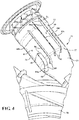
- Figs. 4 , 5 and 6 additionally illustrate that the circumferential spacing between guide vanes 44 can vary to provide control of the flow distribution through the annular passage 23.
- the circumferential spacing between guide vanes 44 can be defined as the spacing between the main bodies 56 of the vanes 44 and/or as the spacing between adjacent vanes 44, measured circumferentially around the combustor assembly 17, at a given axial location along the longitudinal axis 54.
- Fig. 4 shows the first pair of guide vanes 44 formed by the first and second guide vanes 44a, 44b being spaced closer than the second pair of guide vanes 44 formed by the third and fourth guide vanes 44c, 44d.
- Fig. 5 shows the first pair of guide vanes 44a, 44b being spaced generally the same as the spacing between the third and fourth guide vanes 44c, 44d, but with a closer spacing formed between the adjacent guide vanes 44b, 44c of the first and second pairs of guide vanes 44.
- Fig. 6 illustrates a further aspect of the invention in which the first and second vanes 44a, 44b are located in closer circumferentially spaced relation to each other than the spacing between the third and fourth guide vanes 44c, 44d. Further, Fig.
- FIG. 6 shows a configuration in which the fourth guide vane 44d is spaced a greater distance from the third guide vane 44c that the spacing between the other guide vanes 44a, 44b, 44c.
- Fig. 7 shows a further alternative configuration in which an additional guide vane may be provided, and a uniform circumferential spacing can be provided between adjacent vanes 44a-44e.
- each of the variations to the vanes 44 is configured to redistribute the flow around the annular passage 23.
- the shell airflow is not uniformly distributed around the circumference of the combustor assembly 17 as is enters the annular passage 23, and tends to have a high concentration of air flow toward the aft side of the combustor assembly 17.
- the guide vanes 44 effect a greater uniformity in the distribution of the airflow around the circumference of the annular passage, while also reducing swirl in the flow.
- the guide vanes 44 can facilitate cooling by conducting heat from the inner cylinder 24.
- the guide vanes 44 can function to support and maintain a spacing of the inner cylinder 24 relative to the flow sleeve 25.
- flow control guide vanes 44 configured to turn the circumferential swirl flow to a longitudinally extending flow
- additional structure can be provided in the annular passage 23, extending between the inner cylinder 24 and the flow sleeve 25, located around the remaining circumferential regions of the combustor assembly 17 to provide support between the inner cylinder 24 and the flow sleeve 25.
- additional structure would be configured to permit flow of air through the annular passage 23 without requiring the guide vane configuration described for the guide vanes 44.
Description
- The present invention relates in general to turbine engines and, more particularly, to a combustor arrangement for producing a hot working gas that is conveyed from a combustor to turbine blades in a gas turbine engine.
- A gas turbine engine typically includes a compressor section, a combustion section including a plurality of combustors, and a turbine section. Ambient air is compressed in the compressor section and conveyed to the combustors in the combustion section. The combustors combine the compressed air with a fuel and ignite the mixture creating combustion products defining hot working gases that flow in a turbulent manner and at a high velocity. The working gases are routed to the turbine section via a plurality of gas passages, conventionally referred to as transition ducts. Within the turbine section are rows of stationary vane assemblies and rotating blade assemblies. The rotating blade assemblies are coupled to a turbine rotor. As the working gases expand through the turbine section, the working gases cause the blade assemblies, and therefore the turbine rotor, to rotate. The turbine rotor may be linked to an electric generator, wherein the rotation of the turbine rotor can be used to produce electricity in the generator.
- The compressed air is routed between a flow sleeve and an inner cylinder of a respective combustor to provide the air for combustion in a combustion zone surrounded by the inner cylinder. The gas passages each include an inlet positioned adjacent to a respective combustor, and each gas passage routes a flow of working gases into the turbine section through a turbine inlet structure associated with a first row of turbine vanes.
JP 2000 146186 A - In accordance with an aspect of the invention, a can annular gas turbine engine comprising a combustor arrangement is provided in. The gas turbine engine has a gas delivery structure for delivering gases from a plurality of combustors to an annular chamber that extends circumferentially and is oriented concentric to a gas turbine engine axis for delivering the gas flow to a first row of blades. A gas flow path is formed by a duct arrangement between a respective combustor and the annular chamber for conveying gases in a downstream direction from each combustor to the first row of turbine blades. The combustor arrangement comprises a combustor having an inner cylinder surrounding a combustion zone of the combustor. The inner cylinder defines a longitudinal axis of the combustor that is oriented in a radially inward and circumferentially angled direction toward the annular chamber. A cone section is provided having an inlet end receiving the gas flow from the inner cylinder, wherein the cone section defines a decreasing flow area in the downstream direction. A flow sleeve surrounds the inner cylinder, and an annular space is defined between the inner cylinder and the flow sleeve and defines an air flow path having an annular air inlet defined along the inner cylinder radially inward of a junction between the inner cylinder and the cone section. A plurality of guide vanes are located in circumferentially spaced relation to each other in the annular space, spanning between the flow sleeve and the inner cylinder. The guide vanes each have a length dimension defined between a radially inner leading edge and a radially outer trailing edge, wherein the leading edges of the guide vanes are located along the longitudinal axis radially inward from the junction between the inner cylinder and the cone section.
- The leading edge of at least one guide vane can be located radially inward along the longitudinal axis relative to the leading edge of at least one other of the guide vanes.
- Air flowing into the annular space can have a circumferential swirl flow direction around a circumference of the inner cylinder, and the at least one guide vane can be located in an upstream direction of the swirl flow from the at least one other of the guide vanes.
- At least two of the guide vanes can have leading edges located radially inward along the longitudinal axis relative to at least two other of the guide vanes. The at least two of the guide vanes can have trailing edges located radially inward along the longitudinal axis relative to the trailing edges of the at least two other guide vanes.
- A first guide vane can be circumferentially located at an upstream-most location and can have a leading edge at a radially inward location relative to all of the other guide vanes, and can have a length that is less than half the length of the other guide vanes.
- A first guide vane can be circumferentially located at an upstream-most location and can be spaced from an adjacent guide vane a distance that is less than a circumferential spacing between other adjacent guide vanes.
- Each of the guide vanes include a circumferentially angled flow directing portion and an angle of each of the circumferentially angled flow directing portions of the at least two guide vanes, as measured relative to the longitudinal axis, can be greater than an angle of each of the circumferentially angled flow directing portions of the at least two other of the guide vanes.
- All of the guide vanes can be located in a circumferential area that is less than 180 degrees around the circumference of the inner cylinder.
- A radially inner end of the flow sleeve can be located radially inward from the junction between the inner cylinder and the cone section.
- One or more of the guide vanes can include a straight main body aligned parallel to the longitudinal axis of the combustor and extending from the trailing edge to a radially inner intermediate location, and a circumferentially angled flow directing portion extending from the intermediate location to the leading edge.
- Discloses is also a combustor arrangement in a can annular gas turbine engine. The gas turbine engine has a gas delivery structure for delivering gases from a plurality of combustors to an annular chamber that extends circumferentially and is oriented concentric to a gas turbine engine axis for delivering the gas flow to a first row of blades. A gas flow path is formed by a duct arrangement between a respective combustor and the annular chamber for conveying gases in a downstream direction from each combustor to the first row of turbine blades. The combustor arrangement comprises a combustor having an inner cylinder surrounding a combustion zone of the combustor. The inner cylinder defines a longitudinal axis of the combustor that is oriented in a radially inward and circumferentially angled direction toward the annular chamber. A cone section is provided having an inlet end receiving the gas flow from the inner cylinder, wherein the cone section defines a decreasing flow area in the downstream direction. A flow sleeve surrounds the inner cylinder, and an annular space is defined between the inner cylinder and the flow sleeve and defines an air flow path having an annular air inlet defined along the inner cylinder radially inward of a junction between the inner cylinder and the cone section. A plurality of guide vanes are located in circumferentially spaced relation to each other in the annular space, spanning between the flow sleeve and the inner cylinder. The guide vanes each have a length dimension defined between a radially inner leading edge and a radially outer trailing edge, wherein the leading edge of at least one guide vane is located radially inward along the longitudinal axis relative to the leading edge of at least one other of the guide vanes.
- Air flowing into the annular space can have a circumferential swirl flow direction around a circumference of the inner cylinder, and the at least one guide vane can be located in an upstream direction of the swirl flow from the at least one other of the guide vanes.
- A first pair of the guide vanes can have leading edges located radially inward along the longitudinal axis relative to a second pair of the guide vanes, and the first pair of guide vanes can be located in the upstream direction of the swirl flow from the second pair of guide vanes. A first, upstream-most guide vane of the first pair of guide vanes can have a length that is less than the length of the other guide vanes.
- Each of the guide vanes can include a circumferentially angled flow directing portion and an angle of the circumferentially angled flow directing portions of each of the guide vanes in the first pair of guide vanes, as measured relative to the longitudinal axis, can be greater than an angle of each of the circumferentially angled flow directing portions of the guide vanes in the second pair of guide vanes.
- Disclosed is also a combustor arrangement in a can annular gas turbine engine. The gas turbine engine has a gas delivery structure for delivering gases from a plurality of combustors to an annular chamber that extends circumferentially and is oriented concentric to a gas turbine engine axis for delivering the gas flow to a first row of blades. A gas flow path is formed by a duct arrangement between a respective combustor and the annular chamber for conveying gases in a downstream direction from each combustor to the first row of turbine blades. The combustor arrangement comprises a combustor having an inner cylinder surrounding a combustion zone of the combustor. The inner cylinder defines a longitudinal axis of the combustor that is oriented in a radially inward and circumferentially angled direction toward the annular chamber. A cone section is provided having an inlet end receiving the gas flow from the inner cylinder, wherein the cone section defines a decreasing flow area in the downstream direction. A flow sleeve surrounds the inner cylinder, and an annular space is defined between the inner cylinder and the flow sleeve and defines an air flow path having an annular air inlet defined along the inner cylinder radially inward of a junction between the inner cylinder and the cone section. A plurality of guide vanes are located in circumferentially spaced relation to each other in the annular space, spanning between the flow sleeve and the inner cylinder. The guide vanes each have a length dimension defined between a radially inner leading edge and a radially outer trailing edge. Each guide vane includes a circumferentially angled flow directing portion, wherein air flowing into the annular space has a circumferential swirl flow direction around a circumference of the inner cylinder, and a first pair of guide vanes are circumferentially spaced apart a distance that is less than a circumferential spacing between a second pair of guide vanes adjacent to the first pair of guide vanes. The first pair of guide vanes is located in an upstream direction of the swirl flow relative to the second pair of guide vanes.
- Leading edges of the first pair of guide vanes can be located radially inward from leading edges of the second pair of guide vanes. A first, upstream-most guide vane of the first pair of guide vanes can have a length that is less than the length of the other guide vanes.
- While the specification concludes with claims particularly pointing out and distinctly claiming the present invention, it is believed that the present invention will be better understood from the following description in conjunction with the accompanying Drawing Figures, in which like reference numerals identify like elements, and wherein:
-
Fig. 1 is a cross-sectional view through a portion of a turbine engine illustrating aspects of the present invention; -
Fig. 2 is a perspective view, as viewed in an aft direction of the turbine engine, and illustrating a combustor arrangement in accordance with aspects of the invention; -
Fig. 3 is a perspective view of a combustor arrangement, shown with a flow sleeve removed, illustrating aspects of the invention including vanes having varying leading edge locations; -
Fig. 4 is a perspective view of a combustor arrangement, shown with a flow sleeve removed, illustrating aspects of the invention including vanes having varying circumferential spacing; -
Fig. 5 is a perspective view of a combustor arrangement, shown with a flow sleeve removed, illustrating aspects of the invention including vanes having varying vane length; -
Fig. 6 is a perspective view of a combustor arrangement, shown with a flow sleeve removed, illustrating aspects of the invention including vanes having varying circumferential spacing and varying vane length; and -
Fig. 7 is a perspective view of a combustor arrangement, shown with a flow sleeve removed, illustrating aspects of the invention including additional vanes and illustrating upstream vanes having varying vane length. - In the following detailed description of the preferred embodiment, reference is made to the accompanying drawings that form a part hereof, and in which is shown by way of illustration, and not by way of limitation, a specific preferred embodiment in which the invention may be practiced. It is to be understood that other embodiments may be utilized and that changes may be made without departing from the spirit and scope of the present invention.
- One assembly of a system for delivery of hot working gases from combustors to a turbine section of a gas turbine engine, in accordance with an aspect of the invention, orients combustor cans of a gas turbine engine in a tangential arrangement. In particular, combustor cans of a can-annular combustor are each oriented to direct a hot working gas flow through an assembly of components defining gas passages that direct the individual gas flows in a radially inward and circumferentially angled direction into an annular chamber immediately upstream and adjacent a first row of turbine blades in a turbine section of the engine. For example, the arrangement of gas passages providing a flow to an annular chamber may generally correspond to a structure for supplying a flow of gases directly to a first row of turbine blades, without a need for row one turbine vanes as is described, for example, in
U.S. Patent No. 8,230,688 to Wilson et al. As described in the Wilson et al. patent, the gas passage can typically define a straight flow path extending from the combustor to the annular chamber. - Referring to
Fig. 1 , a gas turbine engine 10 is shown including acompressor section 12, acombustion section 14 and a turbine section 16. Thecompressor section 12 compresses ambient air and supplies the compressed air to a plurality of combustor arrangements orassemblies 17 in thecombustion section 14 for combusting fuel and air and delivering the combustion products to the turbine section 16. In the illustrated embodiment, thecombustor assemblies 17 each comprise a can-annular combustor 18, and incoming air to each combustor 18 flows through an annular passage 23 defined between aninner cylinder 24 and aflow sleeve 25 surrounding theinner cylinder 24. Thecombustors 18 combine the compressed air with fuel and ignite the mixture to create combustion products forming a hot working gas flow from each of thecombustors 18. The gas flow is conveyed through a gas delivery structure formed by a duct arrangement of thecombustor assembly 17, comprisingindividual gas paths 20 associated with each of thecombustors 18, to anannular chamber 50 for delivering the gas flows from thecombustors 18 to the turbine section 16. - A portion of the
gas paths 20 is formed theinner cylinders 24 which are connected to and receive the gas flow from arespective combustor 18. Acone section 26 is connected to theinner cylinder 24 at ajunction 27, and receives the gas flow from theinner cylinder 24 and defines a decreasing flow area in a downstream gas flow direction for conveying the gas flow to an integrated exit piece 28 (hereinafter referred to as an "IEP"). Eachgas path 20 extends along alongitudinal axis 54 of theinner cylinder 24 oriented to direct the hot gas flow from thecombustors 18 in a radially inward and circumferentially angled direction toward theIEPs 28, i.e., circumferentially angled relative to anaxis 31 of the gas turbine engine 10. A plurality ofIEPs 28 are provided, one for each combustor 18, and the plurality ofIEPs 28 are connected to form an annular structure defining theannular chamber 50 forward of the turbine section 16. It may be noted that the turbine section 16 does not include a first row of vanes, and the annular structure delivers the gas flow in an aft direction directly to a first row ofturbine blades 30 in the turbine section 16. - As used herein, "forward" refers to an engine inlet side, and "aft" or "rearward" refers to an engine exhaust side with respect to the
axis 31 of the gas turbine engine 10. "Inner" and "outer" refer to radial positions with respect to the gasturbine engine axis 31. "Upstream" and "downstream" are used in a first instance with reference to the flow direction of the hot working gas passing through theinner cylinder 24,cone section 26 andIEP 28. "Upstream" and "downstream" can also be used in a second instance with reference to a flow direction of shell air forming a swirl flow passing in a circumferential direction around the outside of theinner cylinder 24 and thecone section 26 as the shell air passes into the annular passage 23 between theinner cylinder 24 and theflow sleeve 25. "Radially" and "radial direction" refer to a direction extending perpendicular to theaxis 31 of gas turbine engine 10. "Circumferential" is used in a first instance with reference to a flow of swirl air passing around the outside of theinner cylinder 24 and thecone section 26, and "circumferential" can be used in a second instance with reference to a direction extending around theengine axis 31, and lying in a plane perpendicular to theengine axis 31. - As may be seen in
Fig. 2 , eachIEP 28 can include aninlet section 32 having a generally rectangular cross-section, and having anupstream inlet end 34 and adownstream end 36, with reference to the flow of hot working gas in thegas path 20, wherein theinlet end 34 is joined to adownstream outlet end 37 of thecone section 26. Aconnection segment 38 is formed integrally with theinlet section 32 and is located at a radially inner side of theIEP 28. Theconnection segment 38 has a generally rectangular cross-section and is configured to form a junction with anadjacent IEP 28. Theconnected IEPs 28 form the annular chamber 50 (Fig. 1 ) that is open in the aft direction, extending circumferentially and oriented concentric to theaxis 31 of the engine 10 for delivering the hot working gas flow to the first row ofblades 30. - Referring to
Figs. 1 and2 , compressed air from thecompressor 12 flows in an axially aft direction into acombustor shell 40, comprising shell air A1 (Fig. 5 ) that is provided to thecombustors 18. The direction of the shell air A1 flowing to thecombustors 18 has a radial directional component R1 and a circumferential directional component C1 as it enters the annular passage 23. The circumferential component C1 of the shell air flow extends in the same circumferential direction as the circumferential orientation or angle of thegas paths 20. - It should be understood that the pressurized shell air entering the annular passage 23 forms a concentrated jet of air passing radially outward in the
combustor assembly 17 between theinner cylinder 24 and theflow sleeve 25, which concentrated air is referred to herein asswirl air 42 as it enters and passes through the annular passage 23. That is, theswirl air 42 may be understood as being the portion of shell air A1 entering an annular passage 23 of thecombustor assembly 17. The air flowing into the annular passage 23 is substantially concentrated in the aft facing area of the annulus passage 23, wherein a portion of the shell air A1 enters the annular passage 23 along a circumferential portion of thecombustor assembly 17 that extends along the upstream (relative to direction C1) and aft portions of theinner cylinder 24 and, in the absence of a flow control mechanism, can have a large amount of swirl, i.e., non-linear and directionally non-uniform flow, as it flows radially outward in the flow passage 23 toward an inlet passage in fluid communication with the interior flow passage of theinner cylinder 24. The noted circumferential portion of thecombustor assembly 17 corresponds to anaft facing portion 39 of theinner cylinder 24, and may including an upstream facing portion 41(relative to the circumferential direction C2) of theinner cylinder 24, identified by circumferential area or section S1 inFig. 3 . The swirl flow can have a circumferential flow direction C2 (Fig. 3 ) within the flow passage 23 that can result in a non-uniform air flow entering thecombustor 18, and which can consequently result in a destabilized combustion with increased NOx emissions and can increase the possibility of pressure oscillations. - Referring to
Figs. 3 and4 , an aspect of the invention includes providing a set ofguide vanes 44 that can capture and redirect air to provide an increased uniform flow through the annular passage 23. In particular, a set of fourguide vanes 44 are provided within the circumferential section S1, and identified asguide vanes inner cylinder 24 and flowsleeve 25, respectively, i.e., at inner (first) 43 and outer (second) 45 edge locations (Fig. 3 ) relative to a line extending perpendicular to thelongitudinal axis 54 of the combustorinner cylinder 24. The guide vanes 44 can be rigidly attached to theinner cylinder 24 and theflow sleeve 25 at the first andsecond edge locations 43, 45 to provide a structural connection between theinner cylinder 24 and theflow sleeve 25. - The guide vanes 44 are positioned in circumferentially spaced relation to each other around a portion of the
combustor assembly 17 that does not encompass the full circumference of the combustor assembly, which is preferably less than 180 degrees around thecombustor assembly 17, and can preferably be located within a region extending about 90 degrees around the circumference of thecombustor assembly 17. In particular, theguide vanes 44 are preferably located in the aft facing circumferential region defined by the circumferential section S1. - Each
guide vane 44 comprises an elongated thin plate having a uniform thickness between opposing planar flow surfaces, and having a length extending in the direction of thelongitudinal axis 54 between a radially inner leadingedge 46 and a radially outer trailingedge 48. The leadingedge 46 is located in an annular entrance area or inlet 47 (Fig. 1 ) to the annular passage 23 at a longitudinal location radially inward from thejunction 27 between theinner cylinder 24 and thecone section 26. That is, the leadingedges 46 are positioned to interact with the shell air A1 flowing around thecombustor assemblies 17 and direct the air into the annular passage 23. - Each
guide vane 44 can be configured with a straightmain body 56 aligned parallel to thelongitudinal axis 54 of the combustorinner cylinder 24, and extending from the trailingedge 48 to a radially innerintermediate location 58 that is located at or slightly radially outward from thejunction 27. Eachguide vane 44 can further include a circumferentially angledflow directing portion 60 extending from theintermediate location 58 to the leadingedge 46. Theflow directing portion 60 is angled relative to thelongitudinal axis 54 to position the leadingedge 46 upstream, i.e. relative to the circumferential flow direction C2, from themain body 56. Further, theflow directing portion 60 can define a curved or arc shaped flow surface having a concave upstream side facing toward the incoming flow for guiding the initially circumferentially directed flow entering the inlet 47 into the annular passage 23. The angle of theflow directing portion 60 is defined with reference to a line extending tangent to the upstream side of theflow directing portion 60 at theleading edge 46. Alternatively, one or more of theguide vanes 44 can be formed with the circumferentially angledflow direction portion 60 extending the length of theguide vane 44, such as may be the case for one or more of theguide vanes 44 that have a shorter length than theother guide vanes 44, as described below. - In accordance with one aspect of the invention, the leading
edge 46 of at least one of the guide vanes 44 is positioned at a longitudinal location that is radially inward from the longitudinal location of theleading edges 46 of the other guide vanes 44. In particular, at least a first,upstream-most guide vane 44a can have aleading edge 46 that is located radially inward along thelongitudinal axis 54 from theother guide vanes Fig. 3 , a subsequentsecond guide vane 44b can have aleading edge 46 located at a longitudinal location intermediate the location of the leadingedge 46 of thefirst guide vane 44a and the leading edges of downstream third andfourth guide vanes second guide vanes guide vanes 44 that have leadingedges 46 located radially inward from the leadingedges 46 of a subsequent second pair ofguide vanes 44 formed by the third andfourth guide vanes - The leading
edge 46 of each of the guide vanes 44 is the beginning of the air flow control surface for therespective vane 44. The longitudinally staggered locations of theleading edges 46 permits theguide vanes combustor assembly 17 and is formed into a more uniform flow aligned parallel to thelongitudinal axis 54.Figs. 3 and4 additionally illustrate that the circumferentially angledflow directing portion 60 of at least thefirst guide vane 44a, and optionally of the first andsecond guide vanes fourth guide vanes combustor assembly 17 for passage through the annular passage 23. That is, the leading edge entrance angle of theguide vanes 44 can vary to match the angle of the shell air flow around thecombustor assembly 17, as depicted by theflow lines 42 inFig. 3 . - In accordance with another aspect of the invention, the
first guide vane 44a can be formed with a length, measured in a direction parallel to thelongitudinal axis 54, that is less than the lengths of the remainingguide vanes first guide vane 44a can be less than half the length of theother guide vanes second guide vane 44b can be less than the length of the third andfourth guide vanes edges 48 of the first andsecond guide vanes edges 48 of the third andfourth guide vanes edges 48 of the first andsecond guide vanes second guide vanes inner cylinder 24. -
Figs. 4 ,5 and6 additionally illustrate that the circumferential spacing betweenguide vanes 44 can vary to provide control of the flow distribution through the annular passage 23. The circumferential spacing betweenguide vanes 44 can be defined as the spacing between themain bodies 56 of thevanes 44 and/or as the spacing betweenadjacent vanes 44, measured circumferentially around thecombustor assembly 17, at a given axial location along thelongitudinal axis 54. -
Fig. 4 shows the first pair ofguide vanes 44 formed by the first andsecond guide vanes guide vanes 44 formed by the third andfourth guide vanes Fig. 5 shows the first pair ofguide vanes fourth guide vanes adjacent guide vanes guide vanes 44.Fig. 6 illustrates a further aspect of the invention in which the first andsecond vanes fourth guide vanes Fig. 6 shows a configuration in which thefourth guide vane 44d is spaced a greater distance from thethird guide vane 44c that the spacing between theother guide vanes Fig. 7 shows a further alternative configuration in which an additional guide vane may be provided, and a uniform circumferential spacing can be provided betweenadjacent vanes 44a-44e. - It may be understood that each of the variations to the
vanes 44, as described above with reference toFigs. 3-7 , i.e., variations to the location of leadingedges 46, lengths ofvanes 44 and spacing ofvanes 44, is configured to redistribute the flow around the annular passage 23. As noted above, the shell airflow is not uniformly distributed around the circumference of thecombustor assembly 17 as is enters the annular passage 23, and tends to have a high concentration of air flow toward the aft side of thecombustor assembly 17. In accordance with an aspect of the invention, theguide vanes 44 effect a greater uniformity in the distribution of the airflow around the circumference of the annular passage, while also reducing swirl in the flow. - In addition to increasing the uniformity and reducing swirl of the flow in the annular passage 23, the
guide vanes 44 can facilitate cooling by conducting heat from theinner cylinder 24. In addition, theguide vanes 44 can function to support and maintain a spacing of theinner cylinder 24 relative to theflow sleeve 25. - It may be noted that although the flow
control guide vanes 44, configured to turn the circumferential swirl flow to a longitudinally extending flow, are limited to the region S1, additional structure (not shown) can be provided in the annular passage 23, extending between theinner cylinder 24 and theflow sleeve 25, located around the remaining circumferential regions of thecombustor assembly 17 to provide support between theinner cylinder 24 and theflow sleeve 25. However, it should be understood that such additional structure would be configured to permit flow of air through the annular passage 23 without requiring the guide vane configuration described for the guide vanes 44. - While particular embodiments of the present invention have been illustrated and described, it would be obvious to those skilled in the art that various other changes and modifications can be made without departing from the scope of the invention. It is therefore intended to cover in the appended claims all such changes and modifications that are within the scope of this invention.
Claims (11)
- A can annular gas turbine engine (10) having a gas delivery structure for delivering gases from a plurality of combustors to an annular chamber that extends circumferentially and is oriented concentric to a gas turbine engine axis for delivering the gas flow to a first row of blades, a gas flow path formed by a duct arrangement between a respective combustor and the annular chamber for conveying gases in a downstream direction from each combustor to the first row of turbine blades, wherein a combustor arrangement comprises:a combustor (18) having an inner cylinder (24) surrounding a combustion zone of the combustor, the inner cylinder defining a longitudinal axis of the combustor that is oriented in a radially inward and circumferentially angled direction toward the annular chamber;a cone section (26) having an inlet end receiving the gas flow from the inner cylinder, wherein the cone section defines a decreasing flow area in the downstream direction;a flow sleeve (25) surrounding the inner cylinder;an annular space defined between the inner cylinder and the flow sleeve and defining an air flow path having an annular air inlet defined along the inner cylinder radially inward of a junction (27) between the inner cylinder and the cone section; anda plurality of guide vanes (44) located in circumferentially spaced relation to each other in the annular space, spanning between the flow sleeve and the inner cylinder, the guide vanes each having a length dimension defined between a radially inner leading edge (46) and a radially outer trailing edge (48), wherein the leading edges of the guide vanes are located along the longitudinal axis radially inward from the junction between the inner cylinder and the cone section.
- The combustor arrangement of claim 1, wherein the leading edge (46) of at least one guide vane is located radially inward along the longitudinal axis relative to the leading edge of at least one other of the guide vanes.
- The combustor arrangement of claim 2, wherein air flowing into the annular space has a circumferential swirl flow direction around a circumference of the inner cylinder, and the at least one guide vane is located in an upstream direction of the swirl flow from the at least one other of the guide vanes.
- The combustor arrangement of claim 3, wherein at least two of the guide vanes have leading edges located radially inward along the longitudinal axis relative to at least two other of the guide vanes.
- The combustor arrangement of claim 4, wherein the at least two of the guide vanes have trailing edges located radially inward along the longitudinal axis relative to the trailing edges of the at least two other guide vanes.
- The combustor arrangement of claim 4, wherein a first guide vane (44a) is circumferentially located at an upstream-most location and has a leading edge at a radially inward location relative to all of the other guide vanes, and has a length that is less than half the length of the other guide vanes.
- The combustor arrangement of claim 4, wherein a first guide vane is circumferentially located at an upstream-most location and is spaced from an adjacent guide vane a distance that is less than a circumferential spacing between other adjacent guide vanes.
- The combustor arrangement of claim 4, wherein each of the guide vanes include a circumferentially angled flow directing portion and an angle of each of the circumferentially angled flow directing portions of the at least two guide vanes, as measured relative to the longitudinal axis, is greater than an angle of each of the circumferentially angled flow directing portions of the at least two other of the guide vanes.
- The combustor arrangement of claim 1, wherein all of the guide vanes are located in a circumferential area that is less than 180 degrees around the circumference of the inner cylinder.
- The combustor arrangement of claim 1, wherein a radially inner end of the flow sleeve is located radially inward from the junction between the inner cylinder and the cone section.
- The combustor arrangement of claim 1, wherein one or more of the guide vanes includes a straight main body (56) aligned parallel to the longitudinal axis of the combustor and extending from the trailing edge to a radially inner intermediate location, and a circumferentially angled flow directing portion extending from the intermediate location to the leading edge.
Applications Claiming Priority (1)
| Application Number | Priority Date | Filing Date | Title |
|---|---|---|---|
| PCT/US2014/054214 WO2016036381A1 (en) | 2014-09-05 | 2014-09-05 | Combustor arrangement including flow control vanes |
Publications (2)
| Publication Number | Publication Date |
|---|---|
| EP3189276A1 EP3189276A1 (en) | 2017-07-12 |
| EP3189276B1 true EP3189276B1 (en) | 2019-02-06 |
Family
ID=51585222
Family Applications (1)
| Application Number | Title | Priority Date | Filing Date |
|---|---|---|---|
| EP14771705.2A Not-in-force EP3189276B1 (en) | 2014-09-05 | 2014-09-05 | Gas turbine with combustor arrangement including flow control vanes |
Country Status (3)
| Country | Link |
|---|---|
| US (1) | US9982893B2 (en) |
| EP (1) | EP3189276B1 (en) |
| WO (1) | WO2016036381A1 (en) |
Families Citing this family (2)
| Publication number | Priority date | Publication date | Assignee | Title |
|---|---|---|---|---|
| EP3064837B1 (en) * | 2015-03-05 | 2019-05-08 | Ansaldo Energia Switzerland AG | Liner for a gas turbine combustor |
| US10890328B2 (en) * | 2018-11-29 | 2021-01-12 | DOOSAN Heavy Industries Construction Co., LTD | Fin-pin flow guide for efficient transition piece cooling |
Family Cites Families (24)
| Publication number | Priority date | Publication date | Assignee | Title |
|---|---|---|---|---|
| BE482256A (en) | 1947-05-23 | |||
| CH586375A5 (en) * | 1975-06-25 | 1977-03-31 | Bbc Brown Boveri & Cie | |
| US4129985A (en) * | 1975-11-17 | 1978-12-19 | Kawasaki Jukogyo Kabushiki Kaisha | Combustor device of gas turbine engine |
| JPH1082527A (en) | 1996-09-05 | 1998-03-31 | Toshiba Corp | Gas turbine combustor |
| JP2000146186A (en) | 1998-11-10 | 2000-05-26 | Hitachi Ltd | Gas turbine combustor |
| US7721547B2 (en) | 2005-06-27 | 2010-05-25 | Siemens Energy, Inc. | Combustion transition duct providing stage 1 tangential turning for turbine engines |
| US7685823B2 (en) | 2005-10-28 | 2010-03-30 | Power Systems Mfg., Llc | Airflow distribution to a low emissions combustor |
| US8113003B2 (en) | 2008-08-12 | 2012-02-14 | Siemens Energy, Inc. | Transition with a linear flow path for use in a gas turbine engine |
| US8091365B2 (en) | 2008-08-12 | 2012-01-10 | Siemens Energy, Inc. | Canted outlet for transition in a gas turbine engine |
| US8276389B2 (en) * | 2008-09-29 | 2012-10-02 | Siemens Energy, Inc. | Assembly for directing combustion gas |
| US8230688B2 (en) * | 2008-09-29 | 2012-07-31 | Siemens Energy, Inc. | Modular transvane assembly |
| US20100170258A1 (en) | 2009-01-06 | 2010-07-08 | General Electric Company | Cooling apparatus for combustor transition piece |
| US8549861B2 (en) | 2009-01-07 | 2013-10-08 | General Electric Company | Method and apparatus to enhance transition duct cooling in a gas turbine engine |
| US8516822B2 (en) * | 2010-03-02 | 2013-08-27 | General Electric Company | Angled vanes in combustor flow sleeve |
| US8590314B2 (en) | 2010-04-09 | 2013-11-26 | General Electric Company | Combustor liner helical cooling apparatus |
| US20120031099A1 (en) * | 2010-08-04 | 2012-02-09 | Mahesh Bathina | Combustor assembly for use in a turbine engine and methods of assembling same |
| US20120297784A1 (en) | 2011-05-24 | 2012-11-29 | General Electric Company | System and method for flow control in gas turbine engine |
| US9182122B2 (en) * | 2011-10-05 | 2015-11-10 | General Electric Company | Combustor and method for supplying flow to a combustor |
| US20130091848A1 (en) | 2011-10-14 | 2013-04-18 | General Electric Company | Annular flow conditioning member for gas turbomachine combustor assembly |
| US9212823B2 (en) * | 2012-09-06 | 2015-12-15 | General Electric Company | Systems and methods for suppressing combustion driven pressure fluctuations with a premix combustor having multiple premix times |
| US20140090385A1 (en) * | 2012-10-01 | 2014-04-03 | General Electric Company | System and method for swirl flow generation |
| JP6202976B2 (en) * | 2013-10-10 | 2017-09-27 | 三菱日立パワーシステムズ株式会社 | Gas turbine combustor |
| EP2921779B1 (en) * | 2014-03-18 | 2017-12-06 | Ansaldo Energia Switzerland AG | Combustion chamber with cooling sleeve |
| JP6282184B2 (en) * | 2014-06-19 | 2018-02-21 | 三菱日立パワーシステムズ株式会社 | Heat transfer device and gas turbine combustor including the same |
-
2014
- 2014-09-05 US US15/506,055 patent/US9982893B2/en not_active Expired - Fee Related
- 2014-09-05 EP EP14771705.2A patent/EP3189276B1/en not_active Not-in-force
- 2014-09-05 WO PCT/US2014/054214 patent/WO2016036381A1/en active Application Filing
Non-Patent Citations (1)
| Title |
|---|
| None * |
Also Published As
| Publication number | Publication date |
|---|---|
| EP3189276A1 (en) | 2017-07-12 |
| US20170284679A1 (en) | 2017-10-05 |
| WO2016036381A1 (en) | 2016-03-10 |
| US9982893B2 (en) | 2018-05-29 |
Similar Documents
| Publication | Publication Date | Title |
|---|---|---|
| US9810081B2 (en) | Cooled conduit for conveying combustion gases | |
| US8047777B2 (en) | Turbomachine diffuser | |
| US10378774B2 (en) | Annular combustor with scoop ring for gas turbine engine | |
| US20130047618A1 (en) | Wall elements for gas turbine engines | |
| US9488191B2 (en) | Gas turbine diffuser strut including coanda flow injection | |
| US9127554B2 (en) | Gas turbine engine with radial diffuser and shortened mid section | |
| US11415079B2 (en) | Turbo-shaft ejector with flow guide ring | |
| US20130152543A1 (en) | Radial inflow gas turbine engine with advanced transition duct | |
| US20200248905A1 (en) | Rotating detonation combustor with discrete detonation annuli | |
| US20130213046A1 (en) | Late lean injection system | |
| US9593853B2 (en) | Gas flow path for a gas turbine engine | |
| US20230358402A1 (en) | Gas turbomachine diffuser assembly with radial flow splitters | |
| JP6650694B2 (en) | Systems and apparatus related to gas turbine combustors | |
| JP6599167B2 (en) | Combustor cap assembly | |
| EP3189276B1 (en) | Gas turbine with combustor arrangement including flow control vanes | |
| JP6659269B2 (en) | Combustor cap assembly and combustor with combustor cap assembly | |
| EP3376111B1 (en) | Combustor cowl | |
| US9810434B2 (en) | Transition duct system with arcuate ceramic liner for delivering hot-temperature gases in a combustion turbine engine | |
| US11015455B2 (en) | Internally cooled turbine blade with creep reducing divider wall | |
| CA2845192C (en) | Combustor for gas turbine engine |
Legal Events
| Date | Code | Title | Description |
|---|---|---|---|
| STAA | Information on the status of an ep patent application or granted ep patent |
Free format text: STATUS: THE INTERNATIONAL PUBLICATION HAS BEEN MADE |
|
| PUAI | Public reference made under article 153(3) epc to a published international application that has entered the european phase |
Free format text: ORIGINAL CODE: 0009012 |
|
| STAA | Information on the status of an ep patent application or granted ep patent |
Free format text: STATUS: REQUEST FOR EXAMINATION WAS MADE |
|
| 17P | Request for examination filed |
Effective date: 20170222 |
|
| AK | Designated contracting states |
Kind code of ref document: A1 Designated state(s): AL AT BE BG CH CY CZ DE DK EE ES FI FR GB GR HR HU IE IS IT LI LT LU LV MC MK MT NL NO PL PT RO RS SE SI SK SM TR |
|
| AX | Request for extension of the european patent |
Extension state: BA ME |
|
| DAX | Request for extension of the european patent (deleted) | ||
| GRAP | Despatch of communication of intention to grant a patent |
Free format text: ORIGINAL CODE: EPIDOSNIGR1 |
|
| STAA | Information on the status of an ep patent application or granted ep patent |
Free format text: STATUS: GRANT OF PATENT IS INTENDED |
|
| INTG | Intention to grant announced |
Effective date: 20180821 |
|
| GRAS | Grant fee paid |
Free format text: ORIGINAL CODE: EPIDOSNIGR3 |
|
| GRAA | (expected) grant |
Free format text: ORIGINAL CODE: 0009210 |
|
| STAA | Information on the status of an ep patent application or granted ep patent |
Free format text: STATUS: THE PATENT HAS BEEN GRANTED |
|
| AK | Designated contracting states |
Kind code of ref document: B1 Designated state(s): AL AT BE BG CH CY CZ DE DK EE ES FI FR GB GR HR HU IE IS IT LI LT LU LV MC MK MT NL NO PL PT RO RS SE SI SK SM TR |
|
| REG | Reference to a national code |
Ref country code: GB Ref legal event code: FG4D |
|
| REG | Reference to a national code |
Ref country code: CH Ref legal event code: EP Ref country code: AT Ref legal event code: REF Ref document number: 1095149 Country of ref document: AT Kind code of ref document: T Effective date: 20190215 |
|
| REG | Reference to a national code |
Ref country code: DE Ref legal event code: R096 Ref document number: 602014040757 Country of ref document: DE |
|
| REG | Reference to a national code |
Ref country code: IE Ref legal event code: FG4D |
|
| REG | Reference to a national code |
Ref country code: NL Ref legal event code: MP Effective date: 20190206 |
|
| REG | Reference to a national code |
Ref country code: LT Ref legal event code: MG4D |
|
| PG25 | Lapsed in a contracting state [announced via postgrant information from national office to epo] |
Ref country code: LT Free format text: LAPSE BECAUSE OF FAILURE TO SUBMIT A TRANSLATION OF THE DESCRIPTION OR TO PAY THE FEE WITHIN THE PRESCRIBED TIME-LIMIT Effective date: 20190206 Ref country code: NL Free format text: LAPSE BECAUSE OF FAILURE TO SUBMIT A TRANSLATION OF THE DESCRIPTION OR TO PAY THE FEE WITHIN THE PRESCRIBED TIME-LIMIT Effective date: 20190206 Ref country code: SE Free format text: LAPSE BECAUSE OF FAILURE TO SUBMIT A TRANSLATION OF THE DESCRIPTION OR TO PAY THE FEE WITHIN THE PRESCRIBED TIME-LIMIT Effective date: 20190206 Ref country code: NO Free format text: LAPSE BECAUSE OF FAILURE TO SUBMIT A TRANSLATION OF THE DESCRIPTION OR TO PAY THE FEE WITHIN THE PRESCRIBED TIME-LIMIT Effective date: 20190506 Ref country code: FI Free format text: LAPSE BECAUSE OF FAILURE TO SUBMIT A TRANSLATION OF THE DESCRIPTION OR TO PAY THE FEE WITHIN THE PRESCRIBED TIME-LIMIT Effective date: 20190206 Ref country code: PT Free format text: LAPSE BECAUSE OF FAILURE TO SUBMIT A TRANSLATION OF THE DESCRIPTION OR TO PAY THE FEE WITHIN THE PRESCRIBED TIME-LIMIT Effective date: 20190606 |
|
| REG | Reference to a national code |
Ref country code: AT Ref legal event code: MK05 Ref document number: 1095149 Country of ref document: AT Kind code of ref document: T Effective date: 20190206 |
|
| PG25 | Lapsed in a contracting state [announced via postgrant information from national office to epo] |
Ref country code: IS Free format text: LAPSE BECAUSE OF FAILURE TO SUBMIT A TRANSLATION OF THE DESCRIPTION OR TO PAY THE FEE WITHIN THE PRESCRIBED TIME-LIMIT Effective date: 20190606 Ref country code: GR Free format text: LAPSE BECAUSE OF FAILURE TO SUBMIT A TRANSLATION OF THE DESCRIPTION OR TO PAY THE FEE WITHIN THE PRESCRIBED TIME-LIMIT Effective date: 20190507 Ref country code: HR Free format text: LAPSE BECAUSE OF FAILURE TO SUBMIT A TRANSLATION OF THE DESCRIPTION OR TO PAY THE FEE WITHIN THE PRESCRIBED TIME-LIMIT Effective date: 20190206 Ref country code: LV Free format text: LAPSE BECAUSE OF FAILURE TO SUBMIT A TRANSLATION OF THE DESCRIPTION OR TO PAY THE FEE WITHIN THE PRESCRIBED TIME-LIMIT Effective date: 20190206 Ref country code: RS Free format text: LAPSE BECAUSE OF FAILURE TO SUBMIT A TRANSLATION OF THE DESCRIPTION OR TO PAY THE FEE WITHIN THE PRESCRIBED TIME-LIMIT Effective date: 20190206 Ref country code: BG Free format text: LAPSE BECAUSE OF FAILURE TO SUBMIT A TRANSLATION OF THE DESCRIPTION OR TO PAY THE FEE WITHIN THE PRESCRIBED TIME-LIMIT Effective date: 20190506 |
|
| PG25 | Lapsed in a contracting state [announced via postgrant information from national office to epo] |
Ref country code: AL Free format text: LAPSE BECAUSE OF FAILURE TO SUBMIT A TRANSLATION OF THE DESCRIPTION OR TO PAY THE FEE WITHIN THE PRESCRIBED TIME-LIMIT Effective date: 20190206 Ref country code: ES Free format text: LAPSE BECAUSE OF FAILURE TO SUBMIT A TRANSLATION OF THE DESCRIPTION OR TO PAY THE FEE WITHIN THE PRESCRIBED TIME-LIMIT Effective date: 20190206 Ref country code: IT Free format text: LAPSE BECAUSE OF FAILURE TO SUBMIT A TRANSLATION OF THE DESCRIPTION OR TO PAY THE FEE WITHIN THE PRESCRIBED TIME-LIMIT Effective date: 20190206 Ref country code: CZ Free format text: LAPSE BECAUSE OF FAILURE TO SUBMIT A TRANSLATION OF THE DESCRIPTION OR TO PAY THE FEE WITHIN THE PRESCRIBED TIME-LIMIT Effective date: 20190206 Ref country code: RO Free format text: LAPSE BECAUSE OF FAILURE TO SUBMIT A TRANSLATION OF THE DESCRIPTION OR TO PAY THE FEE WITHIN THE PRESCRIBED TIME-LIMIT Effective date: 20190206 Ref country code: EE Free format text: LAPSE BECAUSE OF FAILURE TO SUBMIT A TRANSLATION OF THE DESCRIPTION OR TO PAY THE FEE WITHIN THE PRESCRIBED TIME-LIMIT Effective date: 20190206 Ref country code: DK Free format text: LAPSE BECAUSE OF FAILURE TO SUBMIT A TRANSLATION OF THE DESCRIPTION OR TO PAY THE FEE WITHIN THE PRESCRIBED TIME-LIMIT Effective date: 20190206 Ref country code: SK Free format text: LAPSE BECAUSE OF FAILURE TO SUBMIT A TRANSLATION OF THE DESCRIPTION OR TO PAY THE FEE WITHIN THE PRESCRIBED TIME-LIMIT Effective date: 20190206 |
|
| REG | Reference to a national code |
Ref country code: DE Ref legal event code: R097 Ref document number: 602014040757 Country of ref document: DE |
|
| PG25 | Lapsed in a contracting state [announced via postgrant information from national office to epo] |
Ref country code: PL Free format text: LAPSE BECAUSE OF FAILURE TO SUBMIT A TRANSLATION OF THE DESCRIPTION OR TO PAY THE FEE WITHIN THE PRESCRIBED TIME-LIMIT Effective date: 20190206 Ref country code: SM Free format text: LAPSE BECAUSE OF FAILURE TO SUBMIT A TRANSLATION OF THE DESCRIPTION OR TO PAY THE FEE WITHIN THE PRESCRIBED TIME-LIMIT Effective date: 20190206 |
|
| PLBE | No opposition filed within time limit |
Free format text: ORIGINAL CODE: 0009261 |
|
| STAA | Information on the status of an ep patent application or granted ep patent |
Free format text: STATUS: NO OPPOSITION FILED WITHIN TIME LIMIT |
|
| PG25 | Lapsed in a contracting state [announced via postgrant information from national office to epo] |
Ref country code: AT Free format text: LAPSE BECAUSE OF FAILURE TO SUBMIT A TRANSLATION OF THE DESCRIPTION OR TO PAY THE FEE WITHIN THE PRESCRIBED TIME-LIMIT Effective date: 20190206 |
|
| 26N | No opposition filed |
Effective date: 20191107 |
|
| PG25 | Lapsed in a contracting state [announced via postgrant information from national office to epo] |
Ref country code: SI Free format text: LAPSE BECAUSE OF FAILURE TO SUBMIT A TRANSLATION OF THE DESCRIPTION OR TO PAY THE FEE WITHIN THE PRESCRIBED TIME-LIMIT Effective date: 20190206 |
|
| PG25 | Lapsed in a contracting state [announced via postgrant information from national office to epo] |
Ref country code: TR Free format text: LAPSE BECAUSE OF FAILURE TO SUBMIT A TRANSLATION OF THE DESCRIPTION OR TO PAY THE FEE WITHIN THE PRESCRIBED TIME-LIMIT Effective date: 20190206 |
|
| REG | Reference to a national code |
Ref country code: DE Ref legal event code: R119 Ref document number: 602014040757 Country of ref document: DE |
|
| PG25 | Lapsed in a contracting state [announced via postgrant information from national office to epo] |
Ref country code: MC Free format text: LAPSE BECAUSE OF FAILURE TO SUBMIT A TRANSLATION OF THE DESCRIPTION OR TO PAY THE FEE WITHIN THE PRESCRIBED TIME-LIMIT Effective date: 20190206 |
|
| REG | Reference to a national code |
Ref country code: CH Ref legal event code: PL |
|
| PG25 | Lapsed in a contracting state [announced via postgrant information from national office to epo] |
Ref country code: IE Free format text: LAPSE BECAUSE OF NON-PAYMENT OF DUE FEES Effective date: 20190905 Ref country code: LU Free format text: LAPSE BECAUSE OF NON-PAYMENT OF DUE FEES Effective date: 20190905 Ref country code: DE Free format text: LAPSE BECAUSE OF NON-PAYMENT OF DUE FEES Effective date: 20200401 Ref country code: LI Free format text: LAPSE BECAUSE OF NON-PAYMENT OF DUE FEES Effective date: 20190930 Ref country code: CH Free format text: LAPSE BECAUSE OF NON-PAYMENT OF DUE FEES Effective date: 20190930 |
|
| REG | Reference to a national code |
Ref country code: BE Ref legal event code: MM Effective date: 20190930 |
|
| PG25 | Lapsed in a contracting state [announced via postgrant information from national office to epo] |
Ref country code: BE Free format text: LAPSE BECAUSE OF NON-PAYMENT OF DUE FEES Effective date: 20190930 |
|
| GBPC | Gb: european patent ceased through non-payment of renewal fee |
Effective date: 20190905 |
|
| PG25 | Lapsed in a contracting state [announced via postgrant information from national office to epo] |
Ref country code: GB Free format text: LAPSE BECAUSE OF NON-PAYMENT OF DUE FEES Effective date: 20190905 Ref country code: FR Free format text: LAPSE BECAUSE OF NON-PAYMENT OF DUE FEES Effective date: 20190930 |
|
| PG25 | Lapsed in a contracting state [announced via postgrant information from national office to epo] |
Ref country code: CY Free format text: LAPSE BECAUSE OF FAILURE TO SUBMIT A TRANSLATION OF THE DESCRIPTION OR TO PAY THE FEE WITHIN THE PRESCRIBED TIME-LIMIT Effective date: 20190206 |
|
| PG25 | Lapsed in a contracting state [announced via postgrant information from national office to epo] |
Ref country code: MT Free format text: LAPSE BECAUSE OF FAILURE TO SUBMIT A TRANSLATION OF THE DESCRIPTION OR TO PAY THE FEE WITHIN THE PRESCRIBED TIME-LIMIT Effective date: 20190206 Ref country code: HU Free format text: LAPSE BECAUSE OF FAILURE TO SUBMIT A TRANSLATION OF THE DESCRIPTION OR TO PAY THE FEE WITHIN THE PRESCRIBED TIME-LIMIT; INVALID AB INITIO Effective date: 20140905 |
|
| PG25 | Lapsed in a contracting state [announced via postgrant information from national office to epo] |
Ref country code: MK Free format text: LAPSE BECAUSE OF FAILURE TO SUBMIT A TRANSLATION OF THE DESCRIPTION OR TO PAY THE FEE WITHIN THE PRESCRIBED TIME-LIMIT Effective date: 20190206 |