EP3189216B1 - Mécanisme d'entraînement d'organes de réglage de l'orientation des pales - Google Patents
Mécanisme d'entraînement d'organes de réglage de l'orientation des pales Download PDFInfo
- Publication number
- EP3189216B1 EP3189216B1 EP15767220.5A EP15767220A EP3189216B1 EP 3189216 B1 EP3189216 B1 EP 3189216B1 EP 15767220 A EP15767220 A EP 15767220A EP 3189216 B1 EP3189216 B1 EP 3189216B1
- Authority
- EP
- European Patent Office
- Prior art keywords
- wheel
- adjustment member
- turbomachine
- drive mechanism
- stage
- Prior art date
- Legal status (The legal status is an assumption and is not a legal conclusion. Google has not performed a legal analysis and makes no representation as to the accuracy of the status listed.)
- Active
Links
Images
Classifications
-
- F—MECHANICAL ENGINEERING; LIGHTING; HEATING; WEAPONS; BLASTING
- F01—MACHINES OR ENGINES IN GENERAL; ENGINE PLANTS IN GENERAL; STEAM ENGINES
- F01D—NON-POSITIVE DISPLACEMENT MACHINES OR ENGINES, e.g. STEAM TURBINES
- F01D17/00—Regulating or controlling by varying flow
- F01D17/10—Final actuators
- F01D17/12—Final actuators arranged in stator parts
- F01D17/14—Final actuators arranged in stator parts varying effective cross-sectional area of nozzles or guide conduits
- F01D17/16—Final actuators arranged in stator parts varying effective cross-sectional area of nozzles or guide conduits by means of nozzle vanes
- F01D17/162—Final actuators arranged in stator parts varying effective cross-sectional area of nozzles or guide conduits by means of nozzle vanes for axial flow, i.e. the vanes turning around axes which are essentially perpendicular to the rotor centre line
-
- F—MECHANICAL ENGINEERING; LIGHTING; HEATING; WEAPONS; BLASTING
- F04—POSITIVE - DISPLACEMENT MACHINES FOR LIQUIDS; PUMPS FOR LIQUIDS OR ELASTIC FLUIDS
- F04D—NON-POSITIVE-DISPLACEMENT PUMPS
- F04D29/00—Details, component parts, or accessories
- F04D29/40—Casings; Connections of working fluid
- F04D29/52—Casings; Connections of working fluid for axial pumps
- F04D29/54—Fluid-guiding means, e.g. diffusers
- F04D29/56—Fluid-guiding means, e.g. diffusers adjustable
- F04D29/563—Fluid-guiding means, e.g. diffusers adjustable specially adapted for elastic fluid pumps
-
- F—MECHANICAL ENGINEERING; LIGHTING; HEATING; WEAPONS; BLASTING
- F05—INDEXING SCHEMES RELATING TO ENGINES OR PUMPS IN VARIOUS SUBCLASSES OF CLASSES F01-F04
- F05D—INDEXING SCHEME FOR ASPECTS RELATING TO NON-POSITIVE-DISPLACEMENT MACHINES OR ENGINES, GAS-TURBINES OR JET-PROPULSION PLANTS
- F05D2220/00—Application
- F05D2220/30—Application in turbines
- F05D2220/32—Application in turbines in gas turbines
- F05D2220/323—Application in turbines in gas turbines for aircraft propulsion, e.g. jet engines
-
- F—MECHANICAL ENGINEERING; LIGHTING; HEATING; WEAPONS; BLASTING
- F05—INDEXING SCHEMES RELATING TO ENGINES OR PUMPS IN VARIOUS SUBCLASSES OF CLASSES F01-F04
- F05D—INDEXING SCHEME FOR ASPECTS RELATING TO NON-POSITIVE-DISPLACEMENT MACHINES OR ENGINES, GAS-TURBINES OR JET-PROPULSION PLANTS
- F05D2260/00—Function
- F05D2260/40—Transmission of power
- F05D2260/403—Transmission of power through the shape of the drive components
- F05D2260/4031—Transmission of power through the shape of the drive components as in toothed gearing
-
- F—MECHANICAL ENGINEERING; LIGHTING; HEATING; WEAPONS; BLASTING
- F05—INDEXING SCHEMES RELATING TO ENGINES OR PUMPS IN VARIOUS SUBCLASSES OF CLASSES F01-F04
- F05D—INDEXING SCHEME FOR ASPECTS RELATING TO NON-POSITIVE-DISPLACEMENT MACHINES OR ENGINES, GAS-TURBINES OR JET-PROPULSION PLANTS
- F05D2260/00—Function
- F05D2260/50—Kinematic linkage, i.e. transmission of position
- F05D2260/53—Kinematic linkage, i.e. transmission of position using gears
Definitions
- the invention relates to a mechanism for driving members for adjusting the orientation of the blades of several rectifier stages of a turbomachine.
- the invention relates more particularly to a mechanism for driving two adjustment members making it possible to simultaneously drive the two adjustment members with different movement speeds of one adjustment member relative to the other.
- the compressor and/or turbine of a turbomachine consists of several stages, each stage comprising a gas flow rectifier.
- the modification of the orientation of the rectifier blades is controlled by means of an actuator comprising a control shaft which cooperates with a member associated with each blade or a blade orientation control box.
- the use of a control box is adaptable to any size of turbomachine.
- this solution involves a large number of components, which reduces the accuracy of the system due to the accumulation of clearances between the many components and their respective deformations.
- the document EP 2 626 521 A1 relates to an actuation mechanism for variable vanes in axial-flow gas turbine engines.
- the vanes are variable in that they are rotatable about their main axis, so that the distribution angle of the fluid flow at a rotor stage of a compressor or the like can be varied to improve engine performance.
- the aim of the invention is to propose a drive mechanism for the blade orientation adjustment means which is both compact and has a reduced number of parts.
- the invention provides a drive mechanism as described in claim 1.
- Such a drive mechanism allows the drive and transmission ratio variability functions to be concentrated in a small number of components, thus reducing the mass of the drive mechanism.
- the transmission ratio of the gear stage associated with the second adjustment member is variable depending on the angular position of the drive wheel in the turbomachine.
- the gear stage associated with the second adjustment member is designed to vary the transmission ratio of the gear stage in a non-linear manner.
- the axes of rotation of the two wheels of the gear stage associated with the second adjustment member are parallel and offset from each other.
- one of the two wheels comprises a groove and the other wheel comprises a finger projecting axially relative to said other wheel, the finger being received in the groove and being able to cooperate with the groove to transmit a torque from the first wheel to the second wheel.
- the groove is formed in the first gear and the finger is carried by the second gear.
- the gear stage associated with the first adjustment member comprises a third toothed wheel which is engaged with the drive wheel and a complementary toothed portion of the first adjustment member.
- the invention also relates to an aircraft turbomachine comprising two rectifier stages, the orientation of the blades of which can be modified, characterized in that each rectifier stage comprises a member for adjusting the orientation of the blades of said rectifier stage, the two adjustment members being movable in rotation in the turbomachine around the main axis of the turbomachine and being driven in rotation by a drive mechanism according to the invention.
- each adjustment member comprises a first toothed portion associated with the associated gear stage and a second toothed portion which meshes with a toothed wheel carried by each blade of the associated rectifier stage.
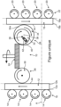
- the single figure shows a mechanism 10 for driving an adjustment member 12 for the orientation of the blades 14 of a first stage 16 of a turbomachine rectifier and an adjustment member 18 for the orientation of the blades 20 of a second stage 22 of the turbomachine rectifier.
- the adjustment members 12, 18 for the orientation of the blades 14, 20 each consist of a ring associated with each rectifier stage 16, 22, which is rotatable in the turbomachine around the main axis of the turbomachine (not shown).
- An axial end 12a, 18a of each ring 12, 18 comprises a toothed portion which cooperates with a toothed wheel carried by each blade 14, 20.
- the orientation of the blades 14, 20 of the two rectifier stages 16, 22 must be modified simultaneously to optimize the performance of the turbomachine. Also, the blades 14 of the first rectifier stage 16 pivot at a different angle relative to the pivot angle of the blades 20 of the second rectifier stage 22.
- the mechanism 10 for driving the adjustment rings 12, 18 is designed to simultaneously drive the two rings 12, 18 in movement and so that the amplitude of movement of the first ring 12, associated with the first rectifier stage 16, is different from the amplitude of movement of the second ring 18 which is associated with the second rectifier stage 22.
- the drive mechanism 10 For the simultaneous driving of the two rings 12, 18, the drive mechanism 10 comprises a single drive wheel 24 which is coupled to the two rings 12, 18 via two gear stages 26, 28.
- the first gear stage 26 is associated with the first ring 12 of the first rectifier stage 16 and it comprises a single toothed wheel 30 which is in mesh with the drive wheel 24 and with the first ring 12.
- the second gear stage 28 is associated with the second ring 18 and it comprises a first toothed wheel 32 which is engaged with the drive wheel 24 and a second toothed wheel 34 which is engaged with the second ring 18.
- the two toothed wheels of the second gear stage 28 cooperate with each other to transmit the driving forces from the first toothed wheel 32 to the second toothed wheel 34.
- each ring 12, 18 comprises for this purpose a toothed portion 44 which cooperates with the wheel 30, 34 of the first gear stage 26 or of the second gear stage 28 which is associated with it.
- the first wheel 32 and the second wheel 34 are coupled to each other to provide a transmission ratio different from the transmission ratio provided by the toothed wheel 30 of the first gear stage 26.
- the transmission ratio provided by the toothed wheel 30 of the first gear stage 26 is linear and is constant regardless of the angular position of the drive wheel 24.
- the transmission ratio provided by the second gear stage 28 is thus non-linear.
- the transmission ratio of the second gear stage 28 is variable and it varies as a function of the angular position of the drive wheel 24, and therefore of the first wheel 32.
- the first wheel 32 and the second wheel 34 are arranged parallel to each other and their respective axes of rotation 36, 38 are parallel and are radially offset from each other.
- the two wheels 32, 34 are coupled by means for varying the transmission ratio of the second gear stage 28.
- These coupling means consist here of a set of groove 40 and follower finger 42, each of which is respectively carried by one or the other of the first or second wheel 32, 34.
- the groove 40 is formed in the first wheel 32 and it has a main radial orientation relative to the axis 36 of rotation of the first wheel 32.
- the finger 42 is carried by the second wheel 34, projecting axially relative to a radial face 34a of the second wheel 34 opposite the first wheel 32 and it is received in the groove 40.
- the invention is not limited to this single configuration of the groove 40 and the finger 42 and that the groove 40 may not be rectilinear, in order to obtain a given law defining the transmission ratio of the second gear stage 28.
- the turbomachine (not shown) comprising the rectifier stages 16, 22 and the drive mechanism 10 defined above is then of simpler structure.
Landscapes
- Engineering & Computer Science (AREA)
- Mechanical Engineering (AREA)
- General Engineering & Computer Science (AREA)
- Structures Of Non-Positive Displacement Pumps (AREA)
- Transmission Devices (AREA)
- Gear Transmission (AREA)
- Supercharger (AREA)
Applications Claiming Priority (2)
| Application Number | Priority Date | Filing Date | Title |
|---|---|---|---|
| FR1458344A FR3025577B1 (fr) | 2014-09-05 | 2014-09-05 | Mecanisme d'entrainement d'organes de reglage de l'orientation des pales |
| PCT/FR2015/052325 WO2016034816A1 (fr) | 2014-09-05 | 2015-09-03 | Mécanisme d'entraînement d'organes de réglage de l'orientation des pales |
Publications (2)
| Publication Number | Publication Date |
|---|---|
| EP3189216A1 EP3189216A1 (fr) | 2017-07-12 |
| EP3189216B1 true EP3189216B1 (fr) | 2025-04-30 |
Family
ID=51932450
Family Applications (1)
| Application Number | Title | Priority Date | Filing Date |
|---|---|---|---|
| EP15767220.5A Active EP3189216B1 (fr) | 2014-09-05 | 2015-09-03 | Mécanisme d'entraînement d'organes de réglage de l'orientation des pales |
Country Status (9)
| Country | Link |
|---|---|
| US (1) | US10502088B2 (enExample) |
| EP (1) | EP3189216B1 (enExample) |
| JP (1) | JP6621807B2 (enExample) |
| CN (1) | CN106687665B (enExample) |
| BR (1) | BR112017003746B1 (enExample) |
| CA (1) | CA2959879C (enExample) |
| FR (1) | FR3025577B1 (enExample) |
| RU (1) | RU2705529C2 (enExample) |
| WO (1) | WO2016034816A1 (enExample) |
Families Citing this family (3)
| Publication number | Priority date | Publication date | Assignee | Title |
|---|---|---|---|---|
| CN108884861B (zh) * | 2016-08-10 | 2020-04-21 | 三菱日立电力系统株式会社 | 轴承装置及旋转机械 |
| FR3057327B1 (fr) * | 2016-10-07 | 2018-12-07 | Safran Aircraft Engines | Mecanisme d'entrainement d'organes de reglage de l'orientation des pales |
| EP4051908B1 (en) * | 2019-10-31 | 2023-12-20 | Daikin Industries, Ltd. | Inlet guide vane actuator assembly |
Family Cites Families (13)
| Publication number | Priority date | Publication date | Assignee | Title |
|---|---|---|---|---|
| GB706139A (en) * | 1950-10-07 | 1954-03-24 | Hellmut Weinrich | Improvements in continuous, automatically regulating gears |
| US5174716A (en) * | 1990-07-23 | 1992-12-29 | General Electric Company | Pitch change mechanism |
| US5498135A (en) * | 1995-01-17 | 1996-03-12 | Newport News Shipbuilding And Dry Dock Company | Actuator for a variable pitch propeller |
| US6039534A (en) * | 1998-09-21 | 2000-03-21 | Northern Research And Engineering Corp | Inlet guide vane assembly |
| FR2856424B1 (fr) | 2003-06-20 | 2005-09-23 | Snecma Moteurs | Dispositif de calage variable de deux etages d'aubes fixes sur un turboreacteur |
| FR2885969B1 (fr) * | 2005-05-17 | 2007-08-10 | Snecma Moteurs Sa | Systeme de commande d'etages d'aubes de stator a angle de calage variable de turbomachine |
| US7665959B2 (en) * | 2005-07-20 | 2010-02-23 | United Technologies Corporation | Rack and pinion variable vane synchronizing mechanism for inner diameter vane shroud |
| US7413401B2 (en) * | 2006-01-17 | 2008-08-19 | General Electric Company | Methods and apparatus for controlling variable stator vanes |
| CN100393985C (zh) * | 2006-10-13 | 2008-06-11 | 成都发动机(集团)有限公司 | 精确调节顶压和紧急全关静叶的调节机构 |
| US8240983B2 (en) * | 2007-10-22 | 2012-08-14 | United Technologies Corp. | Gas turbine engine systems involving gear-driven variable vanes |
| CN202250255U (zh) * | 2011-08-04 | 2012-05-30 | 中国南方航空工业(集团)有限公司 | 涡轮机导向叶片调节器 |
| GB201202383D0 (en) * | 2012-02-13 | 2012-03-28 | Rolls Royce Plc | A unison ring gear assembly |
| FR3030649B1 (fr) * | 2014-12-18 | 2017-01-27 | Snecma | Mecanisme d'entrainement d'organes de reglage de l'orientation des pales |
-
2014
- 2014-09-05 FR FR1458344A patent/FR3025577B1/fr active Active
-
2015
- 2015-09-03 JP JP2017512793A patent/JP6621807B2/ja active Active
- 2015-09-03 WO PCT/FR2015/052325 patent/WO2016034816A1/fr not_active Ceased
- 2015-09-03 CA CA2959879A patent/CA2959879C/fr active Active
- 2015-09-03 CN CN201580047858.6A patent/CN106687665B/zh active Active
- 2015-09-03 BR BR112017003746-7A patent/BR112017003746B1/pt active IP Right Grant
- 2015-09-03 EP EP15767220.5A patent/EP3189216B1/fr active Active
- 2015-09-03 RU RU2017111042A patent/RU2705529C2/ru active
- 2015-09-03 US US15/508,751 patent/US10502088B2/en active Active
Also Published As
| Publication number | Publication date |
|---|---|
| FR3025577B1 (fr) | 2016-12-23 |
| EP3189216A1 (fr) | 2017-07-12 |
| RU2017111042A3 (enExample) | 2019-03-14 |
| BR112017003746B1 (pt) | 2022-10-18 |
| RU2017111042A (ru) | 2018-10-05 |
| JP6621807B2 (ja) | 2019-12-18 |
| CA2959879C (fr) | 2022-09-20 |
| CN106687665B (zh) | 2019-06-14 |
| WO2016034816A1 (fr) | 2016-03-10 |
| US10502088B2 (en) | 2019-12-10 |
| JP2017527736A (ja) | 2017-09-21 |
| CA2959879A1 (fr) | 2016-03-10 |
| RU2705529C2 (ru) | 2019-11-07 |
| BR112017003746A2 (pt) | 2017-12-05 |
| CN106687665A (zh) | 2017-05-17 |
| US20170260870A1 (en) | 2017-09-14 |
| FR3025577A1 (fr) | 2016-03-11 |
Similar Documents
| Publication | Publication Date | Title |
|---|---|---|
| EP3361058B1 (fr) | Compresseur de turbomachine et turbomachine associée | |
| EP2031254B1 (fr) | Étage redresseur de compresseur de turbomachine comprenant une aube à calage variable | |
| EP3189216B1 (fr) | Mécanisme d'entraînement d'organes de réglage de l'orientation des pales | |
| FR3036093A1 (fr) | Dispositif a bras de levier pour la commande de l'orientation des pales de soufflante d'une turbomachine a soufflante non carenee | |
| EP3247885B1 (fr) | Système de commande d'aubes à calage variable pour une turbomachine | |
| WO2016207513A1 (fr) | Système de commande d'aubes à calage variable pour une turbomachine | |
| FR2983235A1 (fr) | Systeme mecanique tournant a actionnement sans contact | |
| EP3382210A1 (fr) | Aube à calage variable de turbomachine, virole de turbomachine, système d'aubes à calage variable, compresseur et turbomachine associés | |
| EP3523555B1 (fr) | Mecanisme d'entrainement d'organes de reglage de l'orientation des pales et turbomachine d'aeronef comprenant ce mecanisme | |
| EP2630335B1 (fr) | Dispositif hydraulique de changement de pas d'helice | |
| FR3027072A1 (fr) | Anneau de commande d'un etage d'aubes a calage variable pour une turbomachine | |
| EP2864594B1 (fr) | Soufflante a calage variable par rotation differentielle des disques de soufflante | |
| FR3030649A1 (fr) | Mecanisme d'entrainement d'organes de reglage de l'orientation des pales | |
| EP4179190B1 (fr) | Méthode et système de régulation de poussée d'une turbomachine d'aéronef | |
| BE1029457B1 (fr) | Ensemble de turbomachine d’aéronef, compresseur, turbomachine et procédé de détermination du calage angulaire d’aubes | |
| WO2016181051A1 (fr) | Dispositif a arbre radial pour la commande de l'orientation des pales de soufflante d'une turbomachine a soufflante non carenee | |
| BE1032075B1 (fr) | Ensemble de turbomachine d'aéronef, compresseur, turbomachine et procédé de fabrication | |
| EP4103820B1 (fr) | Arbre d'entrée flexible tronconique | |
| FR3139859A1 (fr) | Ensemble d’un dispositif d'aubes à calage variable |
Legal Events
| Date | Code | Title | Description |
|---|---|---|---|
| STAA | Information on the status of an ep patent application or granted ep patent |
Free format text: STATUS: THE INTERNATIONAL PUBLICATION HAS BEEN MADE |
|
| PUAI | Public reference made under article 153(3) epc to a published international application that has entered the european phase |
Free format text: ORIGINAL CODE: 0009012 |
|
| STAA | Information on the status of an ep patent application or granted ep patent |
Free format text: STATUS: REQUEST FOR EXAMINATION WAS MADE |
|
| 17P | Request for examination filed |
Effective date: 20170306 |
|
| AK | Designated contracting states |
Kind code of ref document: A1 Designated state(s): AL AT BE BG CH CY CZ DE DK EE ES FI FR GB GR HR HU IE IS IT LI LT LU LV MC MK MT NL NO PL PT RO RS SE SI SK SM TR |
|
| AX | Request for extension of the european patent |
Extension state: BA ME |
|
| DAV | Request for validation of the european patent (deleted) | ||
| DAX | Request for extension of the european patent (deleted) | ||
| STAA | Information on the status of an ep patent application or granted ep patent |
Free format text: STATUS: EXAMINATION IS IN PROGRESS |
|
| 17Q | First examination report despatched |
Effective date: 20200424 |
|
| APBK | Appeal reference recorded |
Free format text: ORIGINAL CODE: EPIDOSNREFNE |
|
| APBN | Date of receipt of notice of appeal recorded |
Free format text: ORIGINAL CODE: EPIDOSNNOA2E |
|
| APBR | Date of receipt of statement of grounds of appeal recorded |
Free format text: ORIGINAL CODE: EPIDOSNNOA3E |
|
| APAF | Appeal reference modified |
Free format text: ORIGINAL CODE: EPIDOSCREFNE |
|
| APBX | Invitation to file observations in appeal sent |
Free format text: ORIGINAL CODE: EPIDOSNOBA2E |
|
| APBZ | Receipt of observations in appeal recorded |
Free format text: ORIGINAL CODE: EPIDOSNOBA4E |
|
| APBT | Appeal procedure closed |
Free format text: ORIGINAL CODE: EPIDOSNNOA9E |
|
| GRAP | Despatch of communication of intention to grant a patent |
Free format text: ORIGINAL CODE: EPIDOSNIGR1 |
|
| STAA | Information on the status of an ep patent application or granted ep patent |
Free format text: STATUS: GRANT OF PATENT IS INTENDED |
|
| GRAS | Grant fee paid |
Free format text: ORIGINAL CODE: EPIDOSNIGR3 |
|
| INTG | Intention to grant announced |
Effective date: 20250225 |
|
| GRAA | (expected) grant |
Free format text: ORIGINAL CODE: 0009210 |
|
| STAA | Information on the status of an ep patent application or granted ep patent |
Free format text: STATUS: THE PATENT HAS BEEN GRANTED |
|
| AK | Designated contracting states |
Kind code of ref document: B1 Designated state(s): AL AT BE BG CH CY CZ DE DK EE ES FI FR GB GR HR HU IE IS IT LI LT LU LV MC MK MT NL NO PL PT RO RS SE SI SK SM TR |
|
| REG | Reference to a national code |
Ref country code: CH Ref legal event code: EP Ref country code: GB Ref legal event code: FG4D Free format text: NOT ENGLISH |
|
| REG | Reference to a national code |
Ref country code: IE Ref legal event code: FG4D Free format text: LANGUAGE OF EP DOCUMENT: FRENCH |
|
| REG | Reference to a national code |
Ref country code: DE Ref legal event code: R096 Ref document number: 602015091542 Country of ref document: DE |
|
| REG | Reference to a national code |
Ref country code: NL Ref legal event code: MP Effective date: 20250430 |
|
| REG | Reference to a national code |
Ref country code: AT Ref legal event code: MK05 Ref document number: 1790196 Country of ref document: AT Kind code of ref document: T Effective date: 20250430 |
|
| PG25 | Lapsed in a contracting state [announced via postgrant information from national office to epo] |
Ref country code: FI Free format text: LAPSE BECAUSE OF FAILURE TO SUBMIT A TRANSLATION OF THE DESCRIPTION OR TO PAY THE FEE WITHIN THE PRESCRIBED TIME-LIMIT Effective date: 20250430 Ref country code: ES Free format text: LAPSE BECAUSE OF FAILURE TO SUBMIT A TRANSLATION OF THE DESCRIPTION OR TO PAY THE FEE WITHIN THE PRESCRIBED TIME-LIMIT Effective date: 20250430 Ref country code: PT Free format text: LAPSE BECAUSE OF FAILURE TO SUBMIT A TRANSLATION OF THE DESCRIPTION OR TO PAY THE FEE WITHIN THE PRESCRIBED TIME-LIMIT Effective date: 20250901 |
|
| PGFP | Annual fee paid to national office [announced via postgrant information from national office to epo] |
Ref country code: DE Payment date: 20250919 Year of fee payment: 11 |
|
| REG | Reference to a national code |
Ref country code: LT Ref legal event code: MG9D |
|
| PG25 | Lapsed in a contracting state [announced via postgrant information from national office to epo] |
Ref country code: NO Free format text: LAPSE BECAUSE OF FAILURE TO SUBMIT A TRANSLATION OF THE DESCRIPTION OR TO PAY THE FEE WITHIN THE PRESCRIBED TIME-LIMIT Effective date: 20250730 Ref country code: GR Free format text: LAPSE BECAUSE OF FAILURE TO SUBMIT A TRANSLATION OF THE DESCRIPTION OR TO PAY THE FEE WITHIN THE PRESCRIBED TIME-LIMIT Effective date: 20250731 |
|
| PG25 | Lapsed in a contracting state [announced via postgrant information from national office to epo] |
Ref country code: PL Free format text: LAPSE BECAUSE OF FAILURE TO SUBMIT A TRANSLATION OF THE DESCRIPTION OR TO PAY THE FEE WITHIN THE PRESCRIBED TIME-LIMIT Effective date: 20250430 Ref country code: NL Free format text: LAPSE BECAUSE OF FAILURE TO SUBMIT A TRANSLATION OF THE DESCRIPTION OR TO PAY THE FEE WITHIN THE PRESCRIBED TIME-LIMIT Effective date: 20250430 |
|
| PG25 | Lapsed in a contracting state [announced via postgrant information from national office to epo] |
Ref country code: BG Free format text: LAPSE BECAUSE OF FAILURE TO SUBMIT A TRANSLATION OF THE DESCRIPTION OR TO PAY THE FEE WITHIN THE PRESCRIBED TIME-LIMIT Effective date: 20250430 |
|
| PGFP | Annual fee paid to national office [announced via postgrant information from national office to epo] |
Ref country code: GB Payment date: 20250923 Year of fee payment: 11 |
|
| PG25 | Lapsed in a contracting state [announced via postgrant information from national office to epo] |
Ref country code: HR Free format text: LAPSE BECAUSE OF FAILURE TO SUBMIT A TRANSLATION OF THE DESCRIPTION OR TO PAY THE FEE WITHIN THE PRESCRIBED TIME-LIMIT Effective date: 20250430 |
|
| PG25 | Lapsed in a contracting state [announced via postgrant information from national office to epo] |
Ref country code: AT Free format text: LAPSE BECAUSE OF FAILURE TO SUBMIT A TRANSLATION OF THE DESCRIPTION OR TO PAY THE FEE WITHIN THE PRESCRIBED TIME-LIMIT Effective date: 20250430 |
|
| PGFP | Annual fee paid to national office [announced via postgrant information from national office to epo] |
Ref country code: FR Payment date: 20250924 Year of fee payment: 11 |
|
| PG25 | Lapsed in a contracting state [announced via postgrant information from national office to epo] |
Ref country code: RS Free format text: LAPSE BECAUSE OF FAILURE TO SUBMIT A TRANSLATION OF THE DESCRIPTION OR TO PAY THE FEE WITHIN THE PRESCRIBED TIME-LIMIT Effective date: 20250731 |
|
| PG25 | Lapsed in a contracting state [announced via postgrant information from national office to epo] |
Ref country code: IS Free format text: LAPSE BECAUSE OF FAILURE TO SUBMIT A TRANSLATION OF THE DESCRIPTION OR TO PAY THE FEE WITHIN THE PRESCRIBED TIME-LIMIT Effective date: 20250830 |
|
| PG25 | Lapsed in a contracting state [announced via postgrant information from national office to epo] |
Ref country code: LV Free format text: LAPSE BECAUSE OF FAILURE TO SUBMIT A TRANSLATION OF THE DESCRIPTION OR TO PAY THE FEE WITHIN THE PRESCRIBED TIME-LIMIT Effective date: 20250430 |
|
| PG25 | Lapsed in a contracting state [announced via postgrant information from national office to epo] |
Ref country code: DK Free format text: LAPSE BECAUSE OF FAILURE TO SUBMIT A TRANSLATION OF THE DESCRIPTION OR TO PAY THE FEE WITHIN THE PRESCRIBED TIME-LIMIT Effective date: 20250430 Ref country code: SM Free format text: LAPSE BECAUSE OF FAILURE TO SUBMIT A TRANSLATION OF THE DESCRIPTION OR TO PAY THE FEE WITHIN THE PRESCRIBED TIME-LIMIT Effective date: 20250430 |
|
| PG25 | Lapsed in a contracting state [announced via postgrant information from national office to epo] |
Ref country code: CZ Free format text: LAPSE BECAUSE OF FAILURE TO SUBMIT A TRANSLATION OF THE DESCRIPTION OR TO PAY THE FEE WITHIN THE PRESCRIBED TIME-LIMIT Effective date: 20250430 |
|
| PG25 | Lapsed in a contracting state [announced via postgrant information from national office to epo] |
Ref country code: EE Free format text: LAPSE BECAUSE OF FAILURE TO SUBMIT A TRANSLATION OF THE DESCRIPTION OR TO PAY THE FEE WITHIN THE PRESCRIBED TIME-LIMIT Effective date: 20250430 |
|
| PG25 | Lapsed in a contracting state [announced via postgrant information from national office to epo] |
Ref country code: SK Free format text: LAPSE BECAUSE OF FAILURE TO SUBMIT A TRANSLATION OF THE DESCRIPTION OR TO PAY THE FEE WITHIN THE PRESCRIBED TIME-LIMIT Effective date: 20250430 Ref country code: RO Free format text: LAPSE BECAUSE OF FAILURE TO SUBMIT A TRANSLATION OF THE DESCRIPTION OR TO PAY THE FEE WITHIN THE PRESCRIBED TIME-LIMIT Effective date: 20250430 |
|
| PG25 | Lapsed in a contracting state [announced via postgrant information from national office to epo] |
Ref country code: IT Free format text: LAPSE BECAUSE OF FAILURE TO SUBMIT A TRANSLATION OF THE DESCRIPTION OR TO PAY THE FEE WITHIN THE PRESCRIBED TIME-LIMIT Effective date: 20250430 |
|
| REG | Reference to a national code |
Ref country code: DE Ref legal event code: R097 Ref document number: 602015091542 Country of ref document: DE |
|
| PLBE | No opposition filed within time limit |
Free format text: ORIGINAL CODE: 0009261 |
|
| STAA | Information on the status of an ep patent application or granted ep patent |
Free format text: STATUS: NO OPPOSITION FILED WITHIN TIME LIMIT |
|
| REG | Reference to a national code |
Ref country code: CH Ref legal event code: L10 Free format text: ST27 STATUS EVENT CODE: U-0-0-L10-L00 (AS PROVIDED BY THE NATIONAL OFFICE) Effective date: 20260311 |
|
| 26N | No opposition filed |
Effective date: 20260202 |
|
| REG | Reference to a national code |
Ref country code: CH Ref legal event code: H13 Free format text: ST27 STATUS EVENT CODE: U-0-0-H10-H13 (AS PROVIDED BY THE NATIONAL OFFICE) Effective date: 20260425 |