EP3189198B1 - Bicycle security device - Google Patents
Bicycle security device Download PDFInfo
- Publication number
- EP3189198B1 EP3189198B1 EP15844332.5A EP15844332A EP3189198B1 EP 3189198 B1 EP3189198 B1 EP 3189198B1 EP 15844332 A EP15844332 A EP 15844332A EP 3189198 B1 EP3189198 B1 EP 3189198B1
- Authority
- EP
- European Patent Office
- Prior art keywords
- component
- bicycle
- lock
- locking ring
- electronics
- Prior art date
- Legal status (The legal status is an assumption and is not a legal conclusion. Google has not performed a legal analysis and makes no representation as to the accuracy of the status listed.)
- Active
Links
Images



Classifications
-
- B—PERFORMING OPERATIONS; TRANSPORTING
- B62—LAND VEHICLES FOR TRAVELLING OTHERWISE THAN ON RAILS
- B62H—CYCLE STANDS; SUPPORTS OR HOLDERS FOR PARKING OR STORING CYCLES; APPLIANCES PREVENTING OR INDICATING UNAUTHORIZED USE OR THEFT OF CYCLES; LOCKS INTEGRAL WITH CYCLES; DEVICES FOR LEARNING TO RIDE CYCLES
- B62H5/00—Appliances preventing or indicating unauthorised use or theft of cycles; Locks integral with cycles
- B62H5/14—Appliances preventing or indicating unauthorised use or theft of cycles; Locks integral with cycles preventing wheel rotation
- B62H5/141—Appliances preventing or indicating unauthorised use or theft of cycles; Locks integral with cycles preventing wheel rotation by means of sliding bolts
-
- B—PERFORMING OPERATIONS; TRANSPORTING
- B62—LAND VEHICLES FOR TRAVELLING OTHERWISE THAN ON RAILS
- B62H—CYCLE STANDS; SUPPORTS OR HOLDERS FOR PARKING OR STORING CYCLES; APPLIANCES PREVENTING OR INDICATING UNAUTHORIZED USE OR THEFT OF CYCLES; LOCKS INTEGRAL WITH CYCLES; DEVICES FOR LEARNING TO RIDE CYCLES
- B62H5/00—Appliances preventing or indicating unauthorised use or theft of cycles; Locks integral with cycles
- B62H5/14—Appliances preventing or indicating unauthorised use or theft of cycles; Locks integral with cycles preventing wheel rotation
- B62H5/147—Appliances preventing or indicating unauthorised use or theft of cycles; Locks integral with cycles preventing wheel rotation by means of circular bolts
-
- B—PERFORMING OPERATIONS; TRANSPORTING
- B62—LAND VEHICLES FOR TRAVELLING OTHERWISE THAN ON RAILS
- B62H—CYCLE STANDS; SUPPORTS OR HOLDERS FOR PARKING OR STORING CYCLES; APPLIANCES PREVENTING OR INDICATING UNAUTHORIZED USE OR THEFT OF CYCLES; LOCKS INTEGRAL WITH CYCLES; DEVICES FOR LEARNING TO RIDE CYCLES
- B62H5/00—Appliances preventing or indicating unauthorised use or theft of cycles; Locks integral with cycles
- B62H5/20—Appliances preventing or indicating unauthorised use or theft of cycles; Locks integral with cycles indicating unauthorised use, e.g. acting on signalling devices
-
- B—PERFORMING OPERATIONS; TRANSPORTING
- B62—LAND VEHICLES FOR TRAVELLING OTHERWISE THAN ON RAILS
- B62J—CYCLE SADDLES OR SEATS; AUXILIARY DEVICES OR ACCESSORIES SPECIALLY ADAPTED TO CYCLES AND NOT OTHERWISE PROVIDED FOR, e.g. ARTICLE CARRIERS OR CYCLE PROTECTORS
- B62J3/00—Acoustic signal devices; Arrangement of such devices on cycles
- B62J3/10—Electrical devices
-
- B—PERFORMING OPERATIONS; TRANSPORTING
- B62—LAND VEHICLES FOR TRAVELLING OTHERWISE THAN ON RAILS
- B62J—CYCLE SADDLES OR SEATS; AUXILIARY DEVICES OR ACCESSORIES SPECIALLY ADAPTED TO CYCLES AND NOT OTHERWISE PROVIDED FOR, e.g. ARTICLE CARRIERS OR CYCLE PROTECTORS
- B62J45/00—Electrical equipment arrangements specially adapted for use as accessories on cycles, not otherwise provided for
- B62J45/20—Cycle computers as cycle accessories
-
- E—FIXED CONSTRUCTIONS
- E05—LOCKS; KEYS; WINDOW OR DOOR FITTINGS; SAFES
- E05B—LOCKS; ACCESSORIES THEREFOR; HANDCUFFS
- E05B39/00—Locks giving indication of authorised or unauthorised unlocking
-
- E—FIXED CONSTRUCTIONS
- E05—LOCKS; KEYS; WINDOW OR DOOR FITTINGS; SAFES
- E05B—LOCKS; ACCESSORIES THEREFOR; HANDCUFFS
- E05B39/00—Locks giving indication of authorised or unauthorised unlocking
- E05B39/005—Locks with means for tracking the location of locked items, e.g. freight containers
-
- E—FIXED CONSTRUCTIONS
- E05—LOCKS; KEYS; WINDOW OR DOOR FITTINGS; SAFES
- E05B—LOCKS; ACCESSORIES THEREFOR; HANDCUFFS
- E05B45/00—Alarm locks
- E05B45/06—Electric alarm locks
-
- E—FIXED CONSTRUCTIONS
- E05—LOCKS; KEYS; WINDOW OR DOOR FITTINGS; SAFES
- E05B—LOCKS; ACCESSORIES THEREFOR; HANDCUFFS
- E05B47/00—Operating or controlling locks or other fastening devices by electric or magnetic means
- E05B47/0001—Operating or controlling locks or other fastening devices by electric or magnetic means with electric actuators; Constructional features thereof
-
- E—FIXED CONSTRUCTIONS
- E05—LOCKS; KEYS; WINDOW OR DOOR FITTINGS; SAFES
- E05B—LOCKS; ACCESSORIES THEREFOR; HANDCUFFS
- E05B47/00—Operating or controlling locks or other fastening devices by electric or magnetic means
- E05B47/0001—Operating or controlling locks or other fastening devices by electric or magnetic means with electric actuators; Constructional features thereof
- E05B47/0012—Operating or controlling locks or other fastening devices by electric or magnetic means with electric actuators; Constructional features thereof with rotary electromotors
-
- E—FIXED CONSTRUCTIONS
- E05—LOCKS; KEYS; WINDOW OR DOOR FITTINGS; SAFES
- E05B—LOCKS; ACCESSORIES THEREFOR; HANDCUFFS
- E05B47/00—Operating or controlling locks or other fastening devices by electric or magnetic means
- E05B47/02—Movement of the bolt by electromagnetic means; Adaptation of locks, latches, or parts thereof, for movement of the bolt by electromagnetic means
- E05B47/023—Movement of the bolt by electromagnetic means; Adaptation of locks, latches, or parts thereof, for movement of the bolt by electromagnetic means the bolt moving pivotally or rotatively
-
- E—FIXED CONSTRUCTIONS
- E05—LOCKS; KEYS; WINDOW OR DOOR FITTINGS; SAFES
- E05B—LOCKS; ACCESSORIES THEREFOR; HANDCUFFS
- E05B71/00—Locks specially adapted for bicycles, other than padlocks
-
- H—ELECTRICITY
- H04—ELECTRIC COMMUNICATION TECHNIQUE
- H04M—TELEPHONIC COMMUNICATION
- H04M1/00—Substation equipment, e.g. for use by subscribers
- H04M1/72—Mobile telephones; Cordless telephones, i.e. devices for establishing wireless links to base stations without route selection
- H04M1/724—User interfaces specially adapted for cordless or mobile telephones
- H04M1/72403—User interfaces specially adapted for cordless or mobile telephones with means for local support of applications that increase the functionality
-
- E—FIXED CONSTRUCTIONS
- E05—LOCKS; KEYS; WINDOW OR DOOR FITTINGS; SAFES
- E05B—LOCKS; ACCESSORIES THEREFOR; HANDCUFFS
- E05B47/00—Operating or controlling locks or other fastening devices by electric or magnetic means
- E05B2047/0048—Circuits, feeding, monitoring
- E05B2047/0067—Monitoring
-
- H—ELECTRICITY
- H04—ELECTRIC COMMUNICATION TECHNIQUE
- H04Q—SELECTING
- H04Q2209/00—Arrangements in telecontrol or telemetry systems
- H04Q2209/40—Arrangements in telecontrol or telemetry systems using a wireless architecture
- H04Q2209/43—Arrangements in telecontrol or telemetry systems using a wireless architecture using wireless personal area networks [WPAN], e.g. 802.15, 802.15.1, 802.15.4, Bluetooth® or Zigbee®
Definitions
- the present invention relates to security devices for bicycles or other vehicles having spoke wheels, or wheels having openings through which a security bar can pass through. More particularly, the present invention is in the field of bicycle locking devices.
- locking devices and systems that can connect to the frame of a bicycle, that lock the drive train of the bicycle, that can give a visual indication to people of the locking device, and that can send a remote indication to a person of the opening or tampering with the locking device or bicycle.
- JP 5567 203 B1 a bicycle sharing system is disclosed.
- the system gives a secured electronic key of a rental bicycle to the bicycle user for making it possible to use the bicycle. There is no hint to the problem of notifying a bicycle being moved by an unauthorized person.
- EP 1 818 246 A also deals with an electronic bicycle lock. It is used for securing the rear wheel of the bicycle. The system is controlled via radio.
- WO 2014/044111 A1 refers to an anti-theft alarming bicycle lock.
- the bicycle lock is connected to a micro motor which can be activated by a radio receiving device and a remote control, so that the bicycle can be wirelessly locked or unlocked.
- the device further comprises an alarm which can be automatically started in a locking state.
- JP 2000 310075 A describes a bicycle lock having a receiving means for generating a signal for operating the lock mechanism portion by driving the lock driving portion with a predetermined power only when the code signal from the transmitting means is coincident with the one set by the authentication code.
- the lock mechanism is locked and unlocked by forward rotation and reverse rotation of the lock drive unit.
- KR 2012 0046659 A discloses a self-lock card key for a bicycle with a GPS module by using a RFID (Radio Frequency Identification) card unit.
- RFID Radio Frequency Identification
- WO 2014/044111 A1 discloses the following features of claim 1; a bicycle locking device comprising:a housing configured to couple to a bicycle frame, wherein a section of the housing forms a housing arc having a gap, and wherein the gap in the housing arc is wider than a bicycle tire width, wherein the housing is comprised of a front casting and a rear casting, wherein the front casting and the rear casting are coupled together by a securing means; a locking ring configured substantially within the housing arc, wherein the housing and the locking ring is configured to move between a first position where the locking ring substantially transects the gap to a second position where the gap is substantially open; an electronic actuator component configured to act on the locking ring to move the locking ring from the first position to the second position, and wherein the electronic actuator is configured to receive an indication to move the locking ring to the first position or to the second position; wherein the bicycle locking device comprises a lock electronics module which includes an electronic communications component, a power supply, and a sound-emit
- the bicycle locking device is comprised of a housing that is coupled to a bicycle frame with a mounting bracket.
- the housing has a housing gap through which the bike wheel passes.
- Within the housing is a locking ring.
- the locking ring is configured to rotate across the housing gap, and thereby move from an unlocked position to a locked position.
- the housing includes an actuator component configured to act upon the locking ring.
- actuator component acts upon the locking ring by engaging gear teeth formed into the locking ring.
- a communications electronic component is configured in the housing.
- the communications component is configured to generate an indication to the actuator to move the locking ring into a locked or unlocked position depending on the message received.
- the bicycle locking device includes an accelerometer electronics component and a sound generation component.
- the accelerometer component detects the motion of the bicycle when locked and is configured to activate the sound generation component when upon detection of motion or other indications of tempering.
- the locking device includes a mounting bracket that couples to the bike and is configured to latch the lock housing to the bracket by an approximate ninety degree turn that cannot be performed when the locking device is locked to a bicycle wheel.
- the locking device includes a GPS receiver that can determine location, position, and velocity.
- the locking device can include a lamp that can be positioned to illuminate either forward or backward. Further, the lamp can be controlled by an accelerometer unit that enables the lamp when decelerating.
- a remote controller in another aspect of the inventive device, has a body containing a transceiver that is configured to communicate wirelessly with the bicycle lock device.
- the remote controller includes a first function that can send a wireless message to the bicycle lock device indicating that the device should be locked.
- the device can include a second button that when asserted sends a wireless message to the bicycle lock to unlock the device.
- the bicycle locking system prevents a bicycle wheel from turning and couples the bike to a secure anchor.
- the locking system 100 is shown in its operational environment.
- the system includes the lock device 10 coupled to a mounting bracket 20 that is coupled a bicycle 70, a locking chain 51, 52, 53, and a wireless controller 30 which includes but is not limited to a smart phone or other mobile device.
- the locking device 10 is coupled to the rear bicycle brake anchor through a bracket 20 designed to couple with a flange 15 which is part of the lock's rear casting 12b. While the lock 10 is shown coupled to the bicycle frame 70 adjacent to the rear wheel 71, the lock device 10 attachment to the front of the bicycle or at other points on the bicycle 70 is contemplated.
- a wireless controller 30 is shown for use by a person to lock and unlock the locking device 10 and receive indications of bicycle 70 tampering.
- the wireless controller 30 can be a phone or other mobile device with wireless capabilities based on protocols for personal area networks or wide area networks, including but not limited to communication protocols based on IEEE 802.15, herein after "Bluetooth".
- Mobile devices include but are not limited to smart phones, personal digital assistants, iPods, and iPads.
- the locking chain 51 and the end rings 52, 53 are used to secure the bicycle 70 to an external anchoring device 60 such as a bike rack.
- the locking system 100 can include a locking chain 51.
- the locking chain 51 includes two rings, 52, 53 coupled to each end of the chain 51.
- One ring 52 is larger than the second ring 53 and has a sufficient inside diameter to pass the chain 51 and smaller ring 53 through the inner opening of the larger ring 52.
- the smaller ring 53 has an inner diameter sufficient for the locking ring 13 to pass through.
- This configuration permits the chain 51 to be put around an anchor 60, around either the bicycle wheel 71 or frame 70, through the large ring 52, and have the locking ring 13 pass though the small ring 53 and thereby securing the bicycle to the anchor 60. While the rings 52, 53 are shown to be circular, other shapes are contemplated.
- the chain 51 can be a cable (not shown) with a small loop on one end and a larger loop on the other end.
- the large loop should have an inner diameter large enough for the smaller loop to pass through.
- the smaller loop and larger loop are sized for the smaller loop to pass through the larger loop.
- the front casting 12a and rear casting 12b includes a locking ring 13, and can include an electronic locking ring actuator, a communications module, and a sound-emitting module, and a power supply module. These modules are shown in Fig. 3 and 8 and described in further detail below.
- the mounting bracket 20 is comprised of a mount anchor bolt 22 and a nut 23 which fits through a centered slot 26 in the bracket 21 and to the bike frame.
- the bracket 21 has two coupling tabs 24a and 24b formed into the bracket 21 and spaced away from a lip 16 configured to engage the lock flange tabs 14a, 14b.
- the anchor bolt 22 and nut 23 is configured to be compatible with coupling to rear bike brake anchor.
- the major components of the lock 10 are a front casting 12a, a rear casting 12b, a locking ring 13 and a lock actuator 47 which is part of the control and communication electronics 40 components.
- the lock actuator 47 and control and communication electronics 40 are contained between the front 12a and rear casting 12b which protects them from the elements and tampering.
- the actuator 47 acts upon the locking ring 13 to move it from a first unlock position to a second locked position and back to a first unlocked position.
- the control electronics component 40 is described further below.
- the locking ring 13 can include teeth 17 formed into the ring 13.
- the teeth 17 are configured to engage with an actuator component 47.
- a worm gear is shown coupled with the actuator motor 47 to act on the locking ring 13. While teeth 17 are shown, other means for acting on the locking ring 13 are contemplated. These include but are not limited to using friction, electromagnetic forces, mechanical linkages, a linear actuator, rack and pinion, a spur gear, lead screw, a retracting spring or a combination thereof to act on the locking ring.
- the locking ring 13 is shown in the unlocked position.
- the locking ring 13 rotates within the housing 12a, 12b between a first position (unlocked) and a second position (locked).
- the locking ring 13 preferably forms a circular arc and is positioned between the front and back casting 12a, 12b which has a channel, guide or groove within the housing casting 12A, 12B.
- a housing gap 11 is substantially open and free from the locking ring 13.
- the locking ring 13 can extend small distance into the gap 11 so long as the locking ring 13 does not interfere with bike wheel 71 rotation.
- the locked position the locking ring 13 transects the housing gap 11 and meets the housing channel on the opposing side.
- one arm 12c of the front and back casting 12a, 12b has extra material to strengthen that arm 12c. This is the arm 12c from which the locking ring 13 rotates out of when locked. Because when in the locked position, one side is strengthened by the locking ring 13 but the other arm 12c is weaker because the locking ring 13 has rotated out of the arm 12c. Therefore, to prevent this weak point, the extra material can be provided in the one arm 12c.
- the locking ring 13 is formed of a strong material that is not easy to cut, bend or break and is not flexible. These materials include but are not limited to steel, stainless steel, metal alloys, aluminum, plastics, or a combination thereof.
- the locking ring end 13a In the open position the locking ring end 13a can be substantially flush with the housing channel. In the locked position, the locking ring transects the housing gap 11.
- the typical width of a bicycle tire is 18-40 millimeters.
- the housing gap 11 can be greater the 40 millimeters to accommodate most bicycle wheels.
- the rear lock casting 12b can include a flange 15 with two flange tabs 14a, 14b. These tabs 14a, 14b and the flange 15 are configured to engage and latch to the mounting bracket 20 when engaged and twisted together to lock the bracket 21 with the flange 15.
- the lock 10 is shown positioned to couple to the mounting bracket 20.
- the lock 10 is positioned approximately ninety degrees rotated from the operating position as shown in Fig. 5 .
- the lock 10, as shown, is slid upward so that the lock flange 15 and flange tabs 14a, 14b slide into a recess in the bracket 21 and rests on a lip 16 inside the bracket 21.
- the lock 10 is then rotated counterclockwise (as shown) which causes the flange tabs 14a, 14b slide between and be held by the lip 16 and the bracket tabs 24a, 24b.
- the fit between the bracket tabs 24a, 24b, the lip 16, and the lock tabs 14a, 14b is sufficiently tight to hold the lock 10 in a secure position.
- the bracket tabs 24a, 24b can even be formed to flex thus providing a tight frictional fit.
- the bracket 21 and the lock flange 15 can have male and female protrusions that engage each other when twisted into in the operating position which will further hold the lock 10 in place.
- the lock 10 is shown in the operating position, coupled to the bracket 21, with the locking bar 13 engaged.
- the lock flange tabs 14a, 14b are behind the bracket tabs 24a, 24b and can be held in place by friction between the bracket tabs 24a, 24b and a lip 16 spaced away from the tabs 24a, 24b running along the inside of the mounting bracket 21.
- FIG. 6 an exploded view of the lock 10 and mounting bracket 20 is shown in relation to the bicycle 70.
- the rear casting 12b can include electronic communication and control component. Referring to Fig. 7 , these components are part of the electronics module 40. These components can include an electronic communications component 41, and a power supply 42, an accelerometer component 43, a temperature sensor component 44, GPS receiver 45, a sound-emitting device 48 if the bicycle locking device 10 is tampered with or the bike moved or combination thereof.
- the electronics 41, 42, 43, 44, 45, 47, 48 and 49 are shown located at the top of the housing but can be located in different locations within the lock 10.
- One skilled in the art of designing wireless communication devices and controllers would know how to design a controller and wireless communication device utilizing the desired protocols and transceivers.
- the remote controller 30 is configured to wirelessly communicate with and control the bicycle lock 10.
- a low power wireless protocol is used including but not limited to Bluetooth.
- the controller can be part of a mobile device with an application installed utilizing the memory, processor, and transceiver resources of the mobile device.
- the mobile device can include but is not limited to smart phones, mobile computers, and personal digital assistants.
- the control functions include but are not limited to locking and unlocking.
- Communication functions can include but are not limited to indications of lock 10 tampering.
- wireless transceiver electronics 31 Communications is provided with wireless transceiver electronics 31 and a power source 32.
- the wireless transceiver electronics 31 can be based on the communication standards including but not limited to Bluetooth IEEE 802.15, WiFi 802.11, Zigbee, cellular protocols, texting protocols or a combination thereof. Further the communication can utilize the Industrial Scientific Medical Band and custom protocols. One skilled in the art of building and designing low power wireless communication devices would be capable of providing these functions.
- the wireless transceiver electronics 31 can include control functions for processing received communications and transmitting control indications. These functions, including control and transceiver functions can be shared with the mobile devices electronics.
- the wireless controller 30 can include one or more buttons for controlling the bicycle lock 10. These buttons can be part of an application on a mobile device.
- the wireless controller 30 can have a first function button 33.
- the first function button 33 can be configured to interface with the wireless communication electronics 31 to generate a bicycle lock 10 unlock message. This message is received by the bicycle lock transceiver component 49.
- the remote controller 30 can have a second function button 34.
- the second function button 34 can be configured to interface with the wireless communication electronics 31 to generate a bicycle lock 10 lock message. This message is received by the bicycle lock transceiver component 49 which results in the locking ring 13 being moved to the lock position.
- buttons are contemplated. Control of the lock 10 can be implemented with a single button and by button pressing sequences. Further, input methods not using buttons are contemplated including but not limited to switches and motion detection devices.
- the wireless controller 30 can be configured to receive an indication that tampering is occurring to the bicycle 70 or bike lock 10. A message is sent from the lock electronics 40 wirelessly to the wireless controller 30 which in turn will generate an indication on the wireless controller 30 or another device that can include but not limited to a mobile phone.
- the controller 30 is transmitting or receiving a wireless signal. This transmission can be either continuously or periodically.
- the strength of the signal from a controller 30 paired with the lock 10 is monitored by either the wireless controller 30 or the lock electronics 40.
- the controller uses the signal strength from the lock electronics 40 to determine that the wireless controller 30 is near the lock 10.
- the wireless controller 30 determines that it is near the lock 10, it can be configured to automatically send a wireless unlock message.
- the lock 10 has to be first installed on the bicycle 70.
- First the bracket 21 needs to be coupled to the bicycle frame 70.
- the bracket 21 is coupled to the bike frame 70 using the rear bike brake anchor bolt mounting hole 72.
- a specially designed anchor bolt 22 is required to accommodate the bike brake and the locking device 10.
- the next step is to couple the lock 10 to the bracket 21.
- the back of the rear casting 12b is configured with a flange 15 with two horizontally orientated flange tabs 14a, 14b.
- the tabs 14a, 14b extends from the center of the flange 15 along a radial line through the center of the flange 15.
- the lock 10 is held substantially perpendicular to plane of the wheel 71 and slid over the mounting bracket 21.
- the mounting bracket 21 has two tabs 24a, 24b located approximately one hundred and eighty degrees from each other and mounted in a substantial horizontal orientation.
- the bracket 21 also has a recess configured to receive the lock flange 15 and lock flange tabs 14a, 14b when substantially vertically orientated.
- the lock 10 is positioned ninety degrees from its installed orientation.
- the bracket 21 has a lip 16 which provides a surface against which the flange tabs 14a, 14b rest.
- the mount tabs 24a, 24b are configured to provide a gap between the lip 16 and the mount tabs 24a, 24b that is equal to the thickness of the flange tabs 14a, 14b.
- the mount tabs 24a, 24b can be configured to flex and thereby allowing the gap to be less than the thickness of the flange tab 14a, 14b.
- the rear bicycle tire 71 is installed.
- the bike rider then rides to a location having an anchor 60 for the bicycle 70.
- the rider then takes his locking chain 51, wraps the chain 51 around an anchor 60 and part of the bike 70 frame, slides the small chain ring 53 through the large chain ring 52 and positions the small chain ring 53 so that when the locking ring 13 moves to the locked position, that the locking ring 13 will pass through the inside of the small ring 53.
- the lock electronics 40 decodes a lock message and actives the actuator 47 which acts upon the lock ring 13.
- the actuator 47 then acts on the lock ring 13 which rotates into a locked position.
- the lock electronics 40 can control a light emitting device to provide an external indication that the bike has an anti-tampering device on it.
- the lock electronics 40 monitors indications of tampering with the bicycle 70. Indication can be movement of the bicycle 70, changes in location as determined by GPS electronics, vibration, or a combination of these indications, the lock 10 sends a wireless message to the wireless device 30 of these indications. Further, when the lock 10 is in a locked configuration and receives a tampering indication, the lock electronics 40 can enable an audible alarm. The rider can then return to the bike and check the bicycle's status.
- the lock electronics 40 can detect that the wireless controller 30 is near the bike by monitoring the wireless signal strength of the device to which it was paired under a protocol such as Bluetooth. Once the strength reaches a predetermined level, which can include other characteristics such as remaining within a signal strength range, the electronics 40 determines that the rider has returned to his bike and automatically causes the lock ring 13 to move to an unlocked position. Such behavior can be configurable.
- the wireless controller 30 monitors the power level from the bicycle and generates an unlock message. Alternatively, the rider asserts a button on the remote controller device 30.
Landscapes
- Engineering & Computer Science (AREA)
- Mechanical Engineering (AREA)
- Physics & Mathematics (AREA)
- Electromagnetism (AREA)
- Acoustics & Sound (AREA)
- Human Computer Interaction (AREA)
- Computer Networks & Wireless Communication (AREA)
- Signal Processing (AREA)
- Lock And Its Accessories (AREA)
Description
- The present invention relates to security devices for bicycles or other vehicles having spoke wheels, or wheels having openings through which a security bar can pass through. More particularly, the present invention is in the field of bicycle locking devices.
- What is needed are locking devices and systems that can connect to the frame of a bicycle, that lock the drive train of the bicycle, that can give a visual indication to people of the locking device, and that can send a remote indication to a person of the opening or tampering with the locking device or bicycle.
- Current bicycle locks prevent a bicycle from being removed from an anchor. However, once the lock or anchor is broken, the bicycle can be ridden or carried away. Once removed, it is often difficult to recover the bicycle and identify the person taking the bike.
- To minimize the likelihood of theft, people have concurrently used multiple types of conventional bicycle locks. However, this has the disadvantage of having to carry multiple locks, the weight of the multiple locks, and having to remember keys and lock combinations for multiple locks. Further, it can be time consuming setting up and unlocking each lock.
- In
JP 5567 203 B1 -
EP 1 818 246 A -
WO 2014/044111 A1 refers to an anti-theft alarming bicycle lock. The bicycle lock is connected to a micro motor which can be activated by a radio receiving device and a remote control, so that the bicycle can be wirelessly locked or unlocked. The device further comprises an alarm which can be automatically started in a locking state.JP 2000 310075 A KR 2012 0046659 A -
WO 2014/044111 A1 discloses the following features ofclaim 1; a bicycle locking device comprising:a housing configured to couple to a bicycle frame, wherein a section of the housing forms a housing arc having a gap, and wherein the gap in the housing arc is wider than a bicycle tire width, wherein the housing is comprised of a front casting and a rear casting, wherein the front casting and the rear casting are coupled together by a securing means;a locking ring configured substantially within the housing arc, wherein the housing and the locking ring is configured to move between a first position where the locking ring substantially transects the gap to a second position where the gap is substantially open; an electronic actuator component configured to act on the locking ring to move the locking ring from the first position to the second position, and wherein the electronic actuator is configured to receive an indication to move the locking ring to the first position or to the second position;wherein the bicycle locking device comprises a lock electronics module which includes an electronic communications component, a power supply, and a sound-emitting device;wherein the lock electronics module is configured to monitor indications of tampering with the bicycle, whereby such indications are movement of the bicycle, vibration, or a combination of these indications;wherein the communication electronics component is coupled to the electronic actuator component, wherein the communication electronics component is configured to generate an indication to the actuator to move the locking ring into a first position or second position, wherein the communication electronics component is configured to wirelessly receive from the second device a lock or unlock message;wherein the electronics component is configured to detect motion of the bicycling locking device when the locking ring is in the first position and wherein the electronics component is configured to activate the sound generating electronics component to output sound when motion is detected. -
-
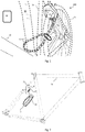
FIG. 1 is an environmental, perspective view of the locking system with the locking device coupled to a bicycle and a chain engaging with the locking ring a securing post. -
FIG. 2 is a side view of the bicycle locking device and mounting bracket. -
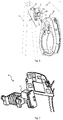
FIG. 3 is an exploded view of the bicycle locking device. -
FIG. 4 is a rear view of the locking device being coupled to the mounting bracket. -
FIG. 5 is an isometric rear view of the lock coupled to the mounting bracket and locked. -
FIG. 6 is an exploded view of the lock and mounting bracket. -
FIG. 7 is a view of the electronics module and the locking ring actuator. -
FIG. 8 is a view of a wireless controller. - The present invention is defined by
claim 1. Various invention embodiments provide an easy convenient way to lock a bicycle. In one embodiment, the bicycle locking device is comprised of a housing that is coupled to a bicycle frame with a mounting bracket. The housing has a housing gap through which the bike wheel passes. Within the housing is a locking ring. The locking ring is configured to rotate across the housing gap, and thereby move from an unlocked position to a locked position. - The housing includes an actuator component configured to act upon the locking ring. In one embodiment that actuator component acts upon the locking ring by engaging gear teeth formed into the locking ring.
- A communications electronic component is configured in the housing. The communications component is configured to generate an indication to the actuator to move the locking ring into a locked or unlocked position depending on the message received.
- The bicycle locking device includes an accelerometer electronics component and a sound generation component. The accelerometer component detects the motion of the bicycle when locked and is configured to activate the sound generation component when upon detection of motion or other indications of tempering.
- The locking device includes a mounting bracket that couples to the bike and is configured to latch the lock housing to the bracket by an approximate ninety degree turn that cannot be performed when the locking device is locked to a bicycle wheel.
- In the same embodiment, the locking device includes a GPS receiver that can determine location, position, and velocity.
- In a further embodiment, the locking device can include a lamp that can be positioned to illuminate either forward or backward. Further, the lamp can be controlled by an accelerometer unit that enables the lamp when decelerating.
- In another aspect of the inventive device, a remote controller is disclosed. The controller has a body containing a transceiver that is configured to communicate wirelessly with the bicycle lock device. The remote controller includes a first function that can send a wireless message to the bicycle lock device indicating that the device should be locked. In a further embodiment, the device can include a second button that when asserted sends a wireless message to the bicycle lock to unlock the device.
- The following description of the invention is provided as an enabling teaching of the invention.
- The bicycle locking system prevents a bicycle wheel from turning and couples the bike to a secure anchor. Referring to
Fig. 1 , thelocking system 100 is shown in its operational environment. The system includes thelock device 10 coupled to amounting bracket 20 that is coupled abicycle 70, alocking chain 51, 52, 53, and awireless controller 30 which includes but is not limited to a smart phone or other mobile device. Thelocking device 10 is coupled to the rear bicycle brake anchor through abracket 20 designed to couple with aflange 15 which is part of the lock'srear casting 12b. While thelock 10 is shown coupled to thebicycle frame 70 adjacent to therear wheel 71, thelock device 10 attachment to the front of the bicycle or at other points on thebicycle 70 is contemplated. - A
wireless controller 30 is shown for use by a person to lock and unlock thelocking device 10 and receive indications ofbicycle 70 tampering. Thewireless controller 30 can be a phone or other mobile device with wireless capabilities based on protocols for personal area networks or wide area networks, including but not limited to communication protocols based on IEEE 802.15, herein after "Bluetooth". Mobile devices include but are not limited to smart phones, personal digital assistants, iPods, and iPads. Thelocking chain 51 and the end rings 52, 53 are used to secure thebicycle 70 to anexternal anchoring device 60 such as a bike rack. - The
locking system 100 can include a lockingchain 51. The lockingchain 51 includes two rings, 52, 53 coupled to each end of thechain 51. One ring 52 is larger than the second ring 53 and has a sufficient inside diameter to pass thechain 51 and smaller ring 53 through the inner opening of the larger ring 52. Further, the smaller ring 53 has an inner diameter sufficient for the lockingring 13 to pass through. This configuration permits thechain 51 to be put around ananchor 60, around either thebicycle wheel 71 orframe 70, through the large ring 52, and have the lockingring 13 pass though the small ring 53 and thereby securing the bicycle to theanchor 60. While the rings 52, 53 are shown to be circular, other shapes are contemplated. Alternatively, thechain 51 can be a cable (not shown) with a small loop on one end and a larger loop on the other end. The large loop should have an inner diameter large enough for the smaller loop to pass through. The smaller loop and larger loop are sized for the smaller loop to pass through the larger loop. - Referring to
Fig. 2 , a side view is shown of thelock 10 and thebracket 20 in relation to the bike frame anchor hole 72. Thefront casting 12a andrear casting 12b includes a lockingring 13, and can include an electronic locking ring actuator, a communications module, and a sound-emitting module, and a power supply module. These modules are shown inFig. 3 and8 and described in further detail below. - Referring to
Fig. 3 , an exploded view of thelock 10 and mountingbracket 20 is shown and described. The mountingbracket 20 is comprised of amount anchor bolt 22 and anut 23 which fits through a centeredslot 26 in thebracket 21 and to the bike frame. Thebracket 21 has twocoupling tabs bracket 21 and spaced away from alip 16 configured to engage thelock flange tabs 14a, 14b. Theanchor bolt 22 andnut 23 is configured to be compatible with coupling to rear bike brake anchor. - The major components of the
lock 10 are afront casting 12a, arear casting 12b, a lockingring 13 and alock actuator 47 which is part of the control andcommunication electronics 40 components. Thelock actuator 47 and control andcommunication electronics 40 are contained between the front 12a andrear casting 12b which protects them from the elements and tampering. - The actuator 47 acts upon the locking
ring 13 to move it from a first unlock position to a second locked position and back to a first unlocked position. Thecontrol electronics component 40 is described further below. - The locking
ring 13 can includeteeth 17 formed into thering 13. Theteeth 17 are configured to engage with anactuator component 47. A worm gear is shown coupled with theactuator motor 47 to act on the lockingring 13. Whileteeth 17 are shown, other means for acting on the lockingring 13 are contemplated. These include but are not limited to using friction, electromagnetic forces, mechanical linkages, a linear actuator, rack and pinion, a spur gear, lead screw, a retracting spring or a combination thereof to act on the locking ring. - The locking
ring 13 is shown in the unlocked position. The lockingring 13 rotates within thehousing ring 13 preferably forms a circular arc and is positioned between the front and back casting 12a, 12b which has a channel, guide or groove within the housing casting 12A, 12B. In the first position (unlocked or retracted position), ahousing gap 11 is substantially open and free from the lockingring 13. The lockingring 13 can extend small distance into thegap 11 so long as the lockingring 13 does not interfere withbike wheel 71 rotation. In the locked position, the lockingring 13 transects thehousing gap 11 and meets the housing channel on the opposing side. - In one embodiment, one
arm 12c of the front and back casting 12a, 12b has extra material to strengthen thatarm 12c. This is thearm 12c from which thelocking ring 13 rotates out of when locked. Because when in the locked position, one side is strengthened by the lockingring 13 but theother arm 12c is weaker because the lockingring 13 has rotated out of thearm 12c. Therefore, to prevent this weak point, the extra material can be provided in the onearm 12c. - Preferably the locking
ring 13 is formed of a strong material that is not easy to cut, bend or break and is not flexible. These materials include but are not limited to steel, stainless steel, metal alloys, aluminum, plastics, or a combination thereof. In the open position the lockingring end 13a can be substantially flush with the housing channel. In the locked position, the locking ring transects thehousing gap 11. The typical width of a bicycle tire is 18-40 millimeters. Thehousing gap 11 can be greater the 40 millimeters to accommodate most bicycle wheels. When thelocking device 10 is mounted on abicycle 30 the lockingring 13 will pass under the rim of the bicycle and prevent thewheel 71 from turning. - The rear lock casting 12b can include a
flange 15 with twoflange tabs 14a, 14b. Thesetabs 14a, 14b and theflange 15 are configured to engage and latch to the mountingbracket 20 when engaged and twisted together to lock thebracket 21 with theflange 15. - Referring to
Fig. 4 , thelock 10 is shown positioned to couple to the mountingbracket 20. Thelock 10 is positioned approximately ninety degrees rotated from the operating position as shown inFig. 5 . Thelock 10, as shown, is slid upward so that thelock flange 15 andflange tabs 14a, 14b slide into a recess in thebracket 21 and rests on alip 16 inside thebracket 21. Thelock 10 is then rotated counterclockwise (as shown) which causes theflange tabs 14a, 14b slide between and be held by thelip 16 and thebracket tabs bracket tabs lip 16, and thelock tabs 14a, 14b is sufficiently tight to hold thelock 10 in a secure position. Thebracket tabs bracket 21 and thelock flange 15 can have male and female protrusions that engage each other when twisted into in the operating position which will further hold thelock 10 in place. - Referring to
Fig. 5 , thelock 10 is shown in the operating position, coupled to thebracket 21, with the lockingbar 13 engaged. Thelock flange tabs 14a, 14b are behind thebracket tabs bracket tabs lip 16 spaced away from thetabs bracket 21. - Referring to
Fig. 6 , an exploded view of thelock 10 and mountingbracket 20 is shown in relation to thebicycle 70. - The
rear casting 12b can include electronic communication and control component. Referring toFig. 7 , these components are part of theelectronics module 40. These components can include an electronic communications component 41, and apower supply 42, anaccelerometer component 43, atemperature sensor component 44,GPS receiver 45, a sound-emittingdevice 48 if thebicycle locking device 10 is tampered with or the bike moved or combination thereof. Theelectronics lock 10. One skilled in the art of designing wireless communication devices and controllers would know how to design a controller and wireless communication device utilizing the desired protocols and transceivers. - Referring to
Fig. 8 , a view of aremote controller 30 is shown. Theremote controller 30 is configured to wirelessly communicate with and control thebicycle lock 10. Preferably, a low power wireless protocol is used including but not limited to Bluetooth. The controller can be part of a mobile device with an application installed utilizing the memory, processor, and transceiver resources of the mobile device. The mobile device can include but is not limited to smart phones, mobile computers, and personal digital assistants. The control functions include but are not limited to locking and unlocking. Communication functions can include but are not limited to indications oflock 10 tampering. - Communications is provided with
wireless transceiver electronics 31 and apower source 32. Thewireless transceiver electronics 31 can be based on the communication standards including but not limited to Bluetooth IEEE 802.15, WiFi 802.11, Zigbee, cellular protocols, texting protocols or a combination thereof. Further the communication can utilize the Industrial Scientific Medical Band and custom protocols. One skilled in the art of building and designing low power wireless communication devices would be capable of providing these functions. Thewireless transceiver electronics 31 can include control functions for processing received communications and transmitting control indications. These functions, including control and transceiver functions can be shared with the mobile devices electronics. - The
wireless controller 30 can include one or more buttons for controlling thebicycle lock 10. These buttons can be part of an application on a mobile device. Thewireless controller 30 can have afirst function button 33. Thefirst function button 33 can be configured to interface with thewireless communication electronics 31 to generate abicycle lock 10 unlock message. This message is received by the bicyclelock transceiver component 49. Further, theremote controller 30 can have asecond function button 34. Thesecond function button 34 can be configured to interface with thewireless communication electronics 31 to generate abicycle lock 10 lock message. This message is received by the bicyclelock transceiver component 49 which results in the lockingring 13 being moved to the lock position. - Other button configurations are contemplated. Control of the
lock 10 can be implemented with a single button and by button pressing sequences. Further, input methods not using buttons are contemplated including but not limited to switches and motion detection devices. - In a further embodiment, the
wireless controller 30 can be configured to receive an indication that tampering is occurring to thebicycle 70 orbike lock 10. A message is sent from thelock electronics 40 wirelessly to thewireless controller 30 which in turn will generate an indication on thewireless controller 30 or another device that can include but not limited to a mobile phone. - In another embodiment, the
controller 30 is transmitting or receiving a wireless signal. This transmission can be either continuously or periodically. The strength of the signal from acontroller 30 paired with thelock 10 is monitored by either thewireless controller 30 or thelock electronics 40. In one embodiment, the controller uses the signal strength from thelock electronics 40 to determine that thewireless controller 30 is near thelock 10. In one embodiment, thewireless controller 30 determines that it is near thelock 10, it can be configured to automatically send a wireless unlock message. - In operation, the
lock 10 has to be first installed on thebicycle 70. First thebracket 21 needs to be coupled to thebicycle frame 70. Preferably, thebracket 21 is coupled to thebike frame 70 using the rear bike brake anchor bolt mounting hole 72. A specially designedanchor bolt 22 is required to accommodate the bike brake and thelocking device 10. Once thebracket 21 is mounted to the bicycle, the rear wheel is removed. - The next step is to couple the
lock 10 to thebracket 21. The back of therear casting 12b is configured with aflange 15 with two horizontally orientatedflange tabs 14a, 14b. Thetabs 14a, 14b extends from the center of theflange 15 along a radial line through the center of theflange 15. Thelock 10 is held substantially perpendicular to plane of thewheel 71 and slid over the mountingbracket 21. The mountingbracket 21 has twotabs bracket 21 also has a recess configured to receive thelock flange 15 andlock flange tabs 14a, 14b when substantially vertically orientated. In this orientation, thelock 10 is positioned ninety degrees from its installed orientation. Thebracket 21 has alip 16 which provides a surface against which theflange tabs 14a, 14b rest. As thelock 10 is rotated and towards its installed position, theflange tabs 14a, 14b will slide between themount tabs lip 16. Themount tabs lip 16 and themount tabs flange tabs 14a, 14b. Further, themount tabs flange tab 14a, 14b. Once thelock 10 rotated to the installed position, thelock 10 is securely coupled to the bicycle by the friction fit of theflange tabs 14a, 14b between thelip 16 andmount tabs - Next the
rear bicycle tire 71 is installed. The bike rider then rides to a location having ananchor 60 for thebicycle 70. The rider then takes hislocking chain 51, wraps thechain 51 around ananchor 60 and part of thebike 70 frame, slides the small chain ring 53 through the large chain ring 52 and positions the small chain ring 53 so that when the lockingring 13 moves to the locked position, that the lockingring 13 will pass through the inside of the small ring 53. - The user then asserts a
lock indicator 33 on thewireless controller 30 which sends a wireless signal, preferably using Bluetooth, which is received by thelock electronics 40. Thelock electronics 40 decodes a lock message and actives theactuator 47 which acts upon thelock ring 13. Alternatively, the user can press a button or switch on thelock 10 which generate a lock indication to thelock electronics 40. Theactuator 47 then acts on thelock ring 13 which rotates into a locked position. Thelock electronics 40 can control a light emitting device to provide an external indication that the bike has an anti-tampering device on it. - While the rider is away from the
bicycle 70, thelock electronics 40 monitors indications of tampering with thebicycle 70. Indication can be movement of thebicycle 70, changes in location as determined by GPS electronics, vibration, or a combination of these indications, thelock 10 sends a wireless message to thewireless device 30 of these indications. Further, when thelock 10 is in a locked configuration and receives a tampering indication, thelock electronics 40 can enable an audible alarm. The rider can then return to the bike and check the bicycle's status. - When the rider is ready to leave, the rider returns to his bike. The
lock electronics 40 can detect that thewireless controller 30 is near the bike by monitoring the wireless signal strength of the device to which it was paired under a protocol such as Bluetooth. Once the strength reaches a predetermined level, which can include other characteristics such as remaining within a signal strength range, theelectronics 40 determines that the rider has returned to his bike and automatically causes thelock ring 13 to move to an unlocked position. Such behavior can be configurable. In another embodiment, thewireless controller 30 monitors the power level from the bicycle and generates an unlock message. Alternatively, the rider asserts a button on theremote controller device 30.
Claims (15)
- A bicycle locking device (10) comprising:a housing (12a, 12b) configured to couple to a bicycle frame (70), wherein a section of the housing (12a, 12b) forms a housing arc having a gap (11), and wherein the gap (11) in the housing arc is wider than a bicycle tire (71) width, wherein the housing (12a, 12b) is comprised of a front casting (12a) and a rear casting (12b), wherein the front casting (12a) and the rear casting (12b) are coupled together by a securing means;a locking ring (13) configured substantially within the housing arc, wherein the housing (12a, 12b) and the locking ring (13) are configured to move between a first position where the locking ring (13) substantially transects the gap (11) to a second position where the gap (11) is substantially open;an electronic actuator component (47) configured to act on the locking ring (13) to move the locking ring (13) from the first position to the second position, and wherein the electronic actuator component (47) is configured to receive an indication to move the locking ring (13) to the first position or to the second position;wherein the bicycle locking device (10) comprises a lock electronics module (40) which includes an electronic communications component (41), a power supply (42), an accelerometer component (43), a GPS receiver (45), and a sound-emitting device (48);wherein the lock electronics module (40) is configured to monitor indications of tampering with the bicycle (70), whereby such indications are movement of the bicycle (70), changes in location as determined by GPS electronics, vibration, or a combination of these indications;wherein the communication electronics component (41) is configured to wirelessly send to a second device (30) an alert indication;wherein the communication electronics component (41) is coupled to the electronic actuator component (47), wherein the communication electronics component (41) is configured to generate an indication to the electronic actuator component (47) to move the locking ring (13) into a first position or second position, wherein the communication electronics component (41) is configured to wirelessly receive from the second device (30) a lock or unlock message;wherein the accelerometer electronics component (43) is configured to detect motion of the bicycling locking device (10) when the locking ring (13) is in the first position and wherein the accelerometer electronics component (43) is configured to activate the sound generating electronics component (48) to output sound when motion or other indications of tampering are detected; anda mounting bracket (20) that is configured to be coupled to the bicycle (70) and is configured to latch the lock housing (12a, 12b) to the bracket (20) by an approximate ninety degree turn that cannot be performed when the locking device (10) is locked to a bicycle wheel (71).
- The device (10) of claim 1, wherein the securing means are bolts having a head requiring a unique tool to be removed.
- The device (10) of claim 1, further comprising a light-emitting component coupled to the communication electronics component (41) and wherein the communication electronics component (41) is configured to enable the light-emitting component when the electronic actuator (47) has received an indication to move the locking ring (13) to the first position.
- The device (10) of claim 1, further comprising a chain (51) having a small ring (53) attached to one end and a larger ring (52) attached to the opposing end, wherein the inner diameter of the large ring (52) is greater than the outer diameter of the small ring (53), and where in inner diameter of the small ring (53) is greater than one half inch.
- The device (10) of claim 1, wherein the generated sound is 80 dB or greater.
- The device (10) of claim 1, the locking ring (13) is configured with gear teeth (17) on a portion of one edge of the locking ring (13), wherein the electronic actuator component (47) is configured to engage with the gear teeth (17) to move the locking ring (13) from to the first position or to the second position.
- The device (10) of claim 1, wherein the bracket (20, 21) configured to be attached a bicycle (70) includes; a flange (15) having two flange tabs (14a, 14b) coupled to the device (10), wherein the bracket (21) has two tabs (24a, 24b) extending from the center of the bracket (21), wherein the mount (21) has a partial circular opening with a lip (16) within the inside of the partially circular opening and wherein the bracket (20) and flange (15) are configured to secure the device (10) when rotated ninety degrees after substantially centering the two flange tabs (14a, 14b) within the partially circular opening.
- The device (10) of claim 1, wherein the GPS receiver (45), is located in the main housing (12a, 12b), and wherein the GPS receiver (45) determines location, position, velocity or a combination thereof.
- The device (10) of claim 1, further comprising a lamp, wherein the lamp is configured to cast a light beam forward, backward, or sideward.
- The device (10) of claim 9, further comprising a lamp control electronics wherein the lamp control electronics includes an accelerometer, and wherein the lamp control electronics activates the lamp when the device detects deceleration.
- A bicycle locking device (10) according to claim 1, 2, 6, and 10 comprisinga light-emitting component coupled to the communication electronics (41) andwherein the communication electronics component (41) is configured to enable the light-emitting component when the electronic actuator (47) has received an indication to move the locking ring (13) to the first position.
- The device (10) of claim 1 further comprising a remote controller device (30) comprising:a body;a transceiver component (31), wherein the transceiver component (31) is configured to communicate wirelessly with the locking device (10);a first function button (33) coupled to the body, wherein the first function button (33) is configured to enable the transceiver (31) to transmit a first function indication;an antenna coupled to the transceiver (31);a notification component selected from one of i) light-emitting device, ii) a vibratory body, and iii) a sound-emitting component, wherein the notification component is activated when the transceiver (31) receive a tampering notification.
- The device (10) of claim 12, wherein the device (10) further comprises a key, wherein the key is configured to turn bolts on a bicycle lock device
- The device (10) of claim 13, wherein the device (10) further comprises a second button (34), wherein the second button (34) is configured to enable the transceiver (31) to transmit a second function indication.
- The device of claim 12, wherein the transceiver component (31) further comprises a Bluetooth module, wherein the Bluetooth module enables communications with a mobile phone.
Applications Claiming Priority (3)
| Application Number | Priority Date | Filing Date | Title |
|---|---|---|---|
| US201462055908P | 2014-09-26 | 2014-09-26 | |
| US14/715,521 US9512649B2 (en) | 2014-09-26 | 2015-05-18 | Bicycle security device |
| PCT/US2015/032365 WO2016048421A1 (en) | 2014-09-26 | 2015-05-26 | Bicycle security device |
Publications (3)
| Publication Number | Publication Date |
|---|---|
| EP3189198A1 EP3189198A1 (en) | 2017-07-12 |
| EP3189198A4 EP3189198A4 (en) | 2018-05-02 |
| EP3189198B1 true EP3189198B1 (en) | 2021-11-24 |
Family
ID=55581716
Family Applications (1)
| Application Number | Title | Priority Date | Filing Date |
|---|---|---|---|
| EP15844332.5A Active EP3189198B1 (en) | 2014-09-26 | 2015-05-26 | Bicycle security device |
Country Status (6)
| Country | Link |
|---|---|
| US (1) | US9512649B2 (en) |
| EP (1) | EP3189198B1 (en) |
| JP (1) | JP3214146U (en) |
| KR (1) | KR20170083033A (en) |
| DK (1) | DK3189198T3 (en) |
| WO (1) | WO2016048421A1 (en) |
Families Citing this family (27)
| Publication number | Priority date | Publication date | Assignee | Title |
|---|---|---|---|---|
| US9932759B2 (en) * | 2014-09-26 | 2018-04-03 | Linka Group Limited | Bicycle security device |
| DE102015005419A1 (en) * | 2015-04-29 | 2016-11-03 | haveltec UG (haftungsbeschränkt) | Automatic two-wheeler lock |
| US10472010B2 (en) * | 2016-10-18 | 2019-11-12 | Cadet Gilomme | Bicycle security system |
| WO2018080622A1 (en) * | 2016-10-29 | 2018-05-03 | Linka Technologies Llc | Bicycle security device |
| CN107120002A (en) * | 2017-04-11 | 2017-09-01 | 上海钧丰网络科技有限公司 | Bicycle intelligent electronic lock |
| USD822452S1 (en) * | 2017-04-21 | 2018-07-10 | Vbikes Technology LLC | Smart bicycle lock |
| WO2018196878A1 (en) | 2017-04-29 | 2018-11-01 | 成都海存艾匹科技有限公司 | Infrared sensor-based shared bike |
| US10562580B2 (en) | 2017-04-29 | 2020-02-18 | HangZhou HaiCun Information Technology Co., Ltd. | Shared infrared (IR) bicycle and methods |
| CN107150737B (en) * | 2017-05-11 | 2019-05-31 | 杭州力谱科技有限公司 | A kind of self-locking intelligent sharing bicycle |
| US10053889B1 (en) | 2017-07-18 | 2018-08-21 | Peter Maratos | Key and cable-style lock |
| US10183713B1 (en) * | 2017-11-06 | 2019-01-22 | LINKA Group Ltd. | Electronic security device for a bicycle |
| WO2019091395A1 (en) * | 2017-11-07 | 2019-05-16 | Neutron Holdings, Inc. | Systems and methods for vehicle parkinhg management |
| NO344445B1 (en) * | 2017-11-28 | 2019-12-09 | Urban Sharing As | Bicycle locking system |
| DE102018111296A1 (en) * | 2018-05-11 | 2019-11-14 | ABUS August Bremicker Söhne KG | Mobile castle |
| GB201809399D0 (en) * | 2018-06-07 | 2018-07-25 | Pashley Holdings Ltd | A Cycle and a Dock |
| TWM567725U (en) * | 2018-07-18 | 2018-10-01 | 源文興工業股份有限公司 | Senseable lock structure of bicycle |
| DE102018121245A1 (en) * | 2018-08-30 | 2020-03-05 | ABUS August Bremicker Söhne KG | Two-wheel lock |
| US12037817B2 (en) * | 2019-05-15 | 2024-07-16 | Rad Power Bikes Inc. | Bicycle security devices and system |
| KR102262154B1 (en) * | 2019-11-21 | 2021-06-09 | (주)에이텍티앤 | Mounting structure of smart lock device for bicycle |
| US11702048B2 (en) | 2020-11-25 | 2023-07-18 | Alexander Kandemir | Braking apparatus for a children's kick scooter |
| CN114590344B (en) * | 2020-12-03 | 2024-02-23 | 苏州达方电子有限公司 | Electronic lock |
| USD964843S1 (en) * | 2021-10-28 | 2022-09-27 | Shenzhen Omni Intelligent Technology Co,. Ltd | Electronic horseshoe lock |
| DK202270409A1 (en) * | 2022-08-18 | 2024-02-20 | Laas Aps | A support structure for an o-lock |
| US12179869B2 (en) | 2022-09-23 | 2024-12-31 | Schlage Lock Company Llc | Portable lock apparatus |
| US12146346B2 (en) * | 2022-09-23 | 2024-11-19 | Schlage Lock Company Llc | Attack-resistant ring lock |
| US12252902B2 (en) * | 2022-09-23 | 2025-03-18 | Schlage Lock Company Llc | Portable lock apparatus with status indicator |
| US12195999B2 (en) | 2022-09-23 | 2025-01-14 | Schlage Lock Company Llc | Ring lock with relocking |
Citations (1)
| Publication number | Priority date | Publication date | Assignee | Title |
|---|---|---|---|---|
| KR20120046659A (en) * | 2010-11-02 | 2012-05-10 | 신민석 | Self.lock - card. key for bike |
Family Cites Families (25)
| Publication number | Priority date | Publication date | Assignee | Title |
|---|---|---|---|---|
| US3965709A (en) * | 1975-06-04 | 1976-06-29 | David P. Belke | Bicycle lock |
| DE2836530C3 (en) | 1978-08-21 | 1981-04-16 | Fa. Aug. Winkhaus, 4404 Telgte | Frame lock, in particular for two-wheeled vehicles |
| DK465288D0 (en) * | 1988-08-18 | 1988-08-18 | Basta Laasefab As | LOCKING DEVICE FOR LOADING A BIKE |
| US4980667A (en) * | 1989-10-16 | 1990-12-25 | Steven Ames | Motion sensitive bicycle alarm |
| US4956982A (en) * | 1990-02-09 | 1990-09-18 | Jana Valley | Anti-theft device for garments |
| US6043733A (en) * | 1998-08-19 | 2000-03-28 | Lind; Carl E. | Vehicle lock having an integral alarm and signal transmission means |
| JP4338821B2 (en) * | 1999-04-28 | 2009-10-07 | ブリヂストンサイクル株式会社 | Bicycle lock |
| NL1026805C2 (en) | 2004-08-09 | 2006-02-13 | Stenman Holland Nv | Ring lock for a bicycle. |
| NL1028758C2 (en) | 2005-04-13 | 2006-10-16 | Stenman Holland Nv | Assembly provided with a bicycle lock. |
| DE102005041268A1 (en) * | 2005-08-31 | 2007-03-01 | ABUS August Bremicker Söhne KG | Cycle lock, for a bicycle or motor cycle or moped, is structured to press the bolt back into the locking position against the hoop after a given time span from the bolt release |
| NL1030495C1 (en) * | 2005-11-23 | 2007-05-24 | Meta Plus Nieuwkoop B V | Theft prevention device involves fixed eyelet, rod or bar coupled to lock of bicycle, motor vehicle, trailer or boat and includes deformable connecting component, such as cable or chain |
| EP1818246B1 (en) | 2006-02-14 | 2011-11-30 | ABUS August Bremicker Söhne KG | Electronic bicycle lock |
| US7649447B2 (en) * | 2006-03-02 | 2010-01-19 | Yen-Ho Lu | Wireless bike brake light |
| US20090188285A1 (en) * | 2008-01-28 | 2009-07-30 | Ideal Bike Corp. | Auto lock system for bicycles |
| WO2009158326A2 (en) * | 2008-06-25 | 2009-12-30 | Ingersoll-Rand Company | Portable lock with modular cable |
| MX2013000526A (en) * | 2010-07-15 | 2013-03-22 | Master Lock Co | PADLOCK. |
| WO2014012564A1 (en) * | 2012-07-20 | 2014-01-23 | Velolock Ltd. | Locking device for a bicycle |
| CN202899836U (en) * | 2012-09-24 | 2013-04-24 | 温州沃卡锘斯五金有限公司 | Anti-theft alarm bicycle lock with remote control |
| US9260885B2 (en) | 2012-10-19 | 2016-02-16 | Brian Asquith | Theft deterrent lock |
| US9679429B2 (en) * | 2012-12-03 | 2017-06-13 | 13876 Yukon Inc. | Wireless portable lock system |
| US20140250954A1 (en) * | 2013-03-06 | 2014-09-11 | James F. Buzhardt | Smart padlock |
| DE102013210358A1 (en) * | 2013-06-04 | 2014-12-04 | Robert Bosch Gmbh | Method and device for realizing an electric bicycle lock |
| JP5567203B1 (en) * | 2013-12-14 | 2014-08-06 | 株式会社ボックス | Bicycle sharing system |
| US9109379B1 (en) * | 2014-08-12 | 2015-08-18 | Dog & Bone Holdings Pty Ltd | Keyless padlock, system and method of use |
| US10336385B2 (en) * | 2014-11-05 | 2019-07-02 | Ford Global Technologies, Llc | Proximity-based bicycle alarm |
-
2015
- 2015-05-18 US US14/715,521 patent/US9512649B2/en not_active Expired - Fee Related
- 2015-05-26 DK DK15844332.5T patent/DK3189198T3/en active
- 2015-05-26 EP EP15844332.5A patent/EP3189198B1/en active Active
- 2015-05-26 KR KR1020177011266A patent/KR20170083033A/en not_active Ceased
- 2015-05-26 JP JP2017600091U patent/JP3214146U/en not_active Expired - Fee Related
- 2015-05-26 WO PCT/US2015/032365 patent/WO2016048421A1/en not_active Ceased
Patent Citations (1)
| Publication number | Priority date | Publication date | Assignee | Title |
|---|---|---|---|---|
| KR20120046659A (en) * | 2010-11-02 | 2012-05-10 | 신민석 | Self.lock - card. key for bike |
Also Published As
| Publication number | Publication date |
|---|---|
| WO2016048421A1 (en) | 2016-03-31 |
| US20160090754A1 (en) | 2016-03-31 |
| US9512649B2 (en) | 2016-12-06 |
| EP3189198A4 (en) | 2018-05-02 |
| EP3189198A1 (en) | 2017-07-12 |
| KR20170083033A (en) | 2017-07-17 |
| DK3189198T3 (en) | 2022-02-07 |
| JP3214146U (en) | 2017-12-28 |
Similar Documents
| Publication | Publication Date | Title |
|---|---|---|
| US9512649B2 (en) | Bicycle security device | |
| US9932759B2 (en) | Bicycle security device | |
| US10450021B2 (en) | Anti-theft lock for two-wheel vehicles | |
| US12037817B2 (en) | Bicycle security devices and system | |
| US8819979B2 (en) | Security system | |
| US9014920B1 (en) | Vehicle occupants alert and alarm system | |
| CN108986365B (en) | Mobile alarm device | |
| US20190212086A1 (en) | Gun lock with alarm system supervisory by zone | |
| US10501137B2 (en) | Handlebar lock system | |
| US10538285B2 (en) | Handlebar locking mechanism, handlebar locking device, and moving body | |
| KR20110007069A (en) | Anti-theft function Electric bicycle, its anti-theft method and anti-theft system of electric bicycle | |
| WO2020255003A1 (en) | An electric lock | |
| KR20190076361A (en) | Smart Bike Lock in Saddle | |
| US12391211B2 (en) | Remote vehicle theft-prevention and recovery device | |
| KR200475894Y1 (en) | Helmet for bike that robbery prevention apparatus is readied | |
| WO2018080622A1 (en) | Bicycle security device | |
| CN103419751A (en) | Multifunctional vehicle-mounted intelligent password safe | |
| CN207523842U (en) | Bicycle safety device | |
| US20220073160A1 (en) | Bicycle Anti-theft Apparatus and System Combined With Bottle Holder | |
| CN202472822U (en) | Computer anti-theft alarm system | |
| KR102486199B1 (en) | Smart control apparatus for bicycle | |
| CN201549044U (en) | Wireless anti-theft alarming system | |
| US20240409061A1 (en) | Multi Alarm Device | |
| JP3865099B2 (en) | Anti-theft system | |
| SK500502015A3 (en) | Security anti-theft system for non-motorized vehicles, in particular bicycles |
Legal Events
| Date | Code | Title | Description |
|---|---|---|---|
| STAA | Information on the status of an ep patent application or granted ep patent |
Free format text: STATUS: THE INTERNATIONAL PUBLICATION HAS BEEN MADE |
|
| PUAI | Public reference made under article 153(3) epc to a published international application that has entered the european phase |
Free format text: ORIGINAL CODE: 0009012 |
|
| STAA | Information on the status of an ep patent application or granted ep patent |
Free format text: STATUS: REQUEST FOR EXAMINATION WAS MADE |
|
| 17P | Request for examination filed |
Effective date: 20170405 |
|
| AK | Designated contracting states |
Kind code of ref document: A1 Designated state(s): AL AT BE BG CH CY CZ DE DK EE ES FI FR GB GR HR HU IE IS IT LI LT LU LV MC MK MT NL NO PL PT RO RS SE SI SK SM TR |
|
| AX | Request for extension of the european patent |
Extension state: BA ME |
|
| DAV | Request for validation of the european patent (deleted) | ||
| DAX | Request for extension of the european patent (deleted) | ||
| A4 | Supplementary search report drawn up and despatched |
Effective date: 20180405 |
|
| RIC1 | Information provided on ipc code assigned before grant |
Ipc: B62H 5/14 20060101ALI20180329BHEP Ipc: E05B 71/00 20060101AFI20180329BHEP |
|
| STAA | Information on the status of an ep patent application or granted ep patent |
Free format text: STATUS: EXAMINATION IS IN PROGRESS |
|
| 17Q | First examination report despatched |
Effective date: 20200107 |
|
| REG | Reference to a national code |
Ref country code: DE Ref legal event code: R079 Ref document number: 602015075290 Country of ref document: DE Free format text: PREVIOUS MAIN CLASS: E05B0071000000 Ipc: B62H0005140000 |
|
| RIC1 | Information provided on ipc code assigned before grant |
Ipc: B62H 5/14 20060101AFI20210416BHEP Ipc: B62H 5/20 20060101ALI20210416BHEP |
|
| GRAP | Despatch of communication of intention to grant a patent |
Free format text: ORIGINAL CODE: EPIDOSNIGR1 |
|
| STAA | Information on the status of an ep patent application or granted ep patent |
Free format text: STATUS: GRANT OF PATENT IS INTENDED |
|
| INTG | Intention to grant announced |
Effective date: 20210708 |
|
| GRAS | Grant fee paid |
Free format text: ORIGINAL CODE: EPIDOSNIGR3 |
|
| GRAA | (expected) grant |
Free format text: ORIGINAL CODE: 0009210 |
|
| STAA | Information on the status of an ep patent application or granted ep patent |
Free format text: STATUS: THE PATENT HAS BEEN GRANTED |
|
| AK | Designated contracting states |
Kind code of ref document: B1 Designated state(s): AL AT BE BG CH CY CZ DE DK EE ES FI FR GB GR HR HU IE IS IT LI LT LU LV MC MK MT NL NO PL PT RO RS SE SI SK SM TR |
|
| REG | Reference to a national code |
Ref country code: GB Ref legal event code: FG4D |
|
| REG | Reference to a national code |
Ref country code: AT Ref legal event code: REF Ref document number: 1449667 Country of ref document: AT Kind code of ref document: T Effective date: 20211215 |
|
| REG | Reference to a national code |
Ref country code: DE Ref legal event code: R096 Ref document number: 602015075290 Country of ref document: DE |
|
| REG | Reference to a national code |
Ref country code: IE Ref legal event code: FG4D |
|
| REG | Reference to a national code |
Ref country code: DK Ref legal event code: T3 Effective date: 20220202 |
|
| REG | Reference to a national code |
Ref country code: SE Ref legal event code: TRGR |
|
| REG | Reference to a national code |
Ref country code: NL Ref legal event code: FP |
|
| REG | Reference to a national code |
Ref country code: LT Ref legal event code: MG9D |
|
| REG | Reference to a national code |
Ref country code: AT Ref legal event code: MK05 Ref document number: 1449667 Country of ref document: AT Kind code of ref document: T Effective date: 20211124 |
|
| PG25 | Lapsed in a contracting state [announced via postgrant information from national office to epo] |
Ref country code: RS Free format text: LAPSE BECAUSE OF FAILURE TO SUBMIT A TRANSLATION OF THE DESCRIPTION OR TO PAY THE FEE WITHIN THE PRESCRIBED TIME-LIMIT Effective date: 20211124 Ref country code: LT Free format text: LAPSE BECAUSE OF FAILURE TO SUBMIT A TRANSLATION OF THE DESCRIPTION OR TO PAY THE FEE WITHIN THE PRESCRIBED TIME-LIMIT Effective date: 20211124 Ref country code: FI Free format text: LAPSE BECAUSE OF FAILURE TO SUBMIT A TRANSLATION OF THE DESCRIPTION OR TO PAY THE FEE WITHIN THE PRESCRIBED TIME-LIMIT Effective date: 20211124 Ref country code: BG Free format text: LAPSE BECAUSE OF FAILURE TO SUBMIT A TRANSLATION OF THE DESCRIPTION OR TO PAY THE FEE WITHIN THE PRESCRIBED TIME-LIMIT Effective date: 20220224 Ref country code: AT Free format text: LAPSE BECAUSE OF FAILURE TO SUBMIT A TRANSLATION OF THE DESCRIPTION OR TO PAY THE FEE WITHIN THE PRESCRIBED TIME-LIMIT Effective date: 20211124 |
|
| PG25 | Lapsed in a contracting state [announced via postgrant information from national office to epo] |
Ref country code: IS Free format text: LAPSE BECAUSE OF FAILURE TO SUBMIT A TRANSLATION OF THE DESCRIPTION OR TO PAY THE FEE WITHIN THE PRESCRIBED TIME-LIMIT Effective date: 20220324 Ref country code: PT Free format text: LAPSE BECAUSE OF FAILURE TO SUBMIT A TRANSLATION OF THE DESCRIPTION OR TO PAY THE FEE WITHIN THE PRESCRIBED TIME-LIMIT Effective date: 20220324 Ref country code: PL Free format text: LAPSE BECAUSE OF FAILURE TO SUBMIT A TRANSLATION OF THE DESCRIPTION OR TO PAY THE FEE WITHIN THE PRESCRIBED TIME-LIMIT Effective date: 20211124 Ref country code: NO Free format text: LAPSE BECAUSE OF FAILURE TO SUBMIT A TRANSLATION OF THE DESCRIPTION OR TO PAY THE FEE WITHIN THE PRESCRIBED TIME-LIMIT Effective date: 20220224 Ref country code: LV Free format text: LAPSE BECAUSE OF FAILURE TO SUBMIT A TRANSLATION OF THE DESCRIPTION OR TO PAY THE FEE WITHIN THE PRESCRIBED TIME-LIMIT Effective date: 20211124 Ref country code: HR Free format text: LAPSE BECAUSE OF FAILURE TO SUBMIT A TRANSLATION OF THE DESCRIPTION OR TO PAY THE FEE WITHIN THE PRESCRIBED TIME-LIMIT Effective date: 20211124 Ref country code: GR Free format text: LAPSE BECAUSE OF FAILURE TO SUBMIT A TRANSLATION OF THE DESCRIPTION OR TO PAY THE FEE WITHIN THE PRESCRIBED TIME-LIMIT Effective date: 20220225 Ref country code: ES Free format text: LAPSE BECAUSE OF FAILURE TO SUBMIT A TRANSLATION OF THE DESCRIPTION OR TO PAY THE FEE WITHIN THE PRESCRIBED TIME-LIMIT Effective date: 20211124 |
|
| PG25 | Lapsed in a contracting state [announced via postgrant information from national office to epo] |
Ref country code: SM Free format text: LAPSE BECAUSE OF FAILURE TO SUBMIT A TRANSLATION OF THE DESCRIPTION OR TO PAY THE FEE WITHIN THE PRESCRIBED TIME-LIMIT Effective date: 20211124 Ref country code: SK Free format text: LAPSE BECAUSE OF FAILURE TO SUBMIT A TRANSLATION OF THE DESCRIPTION OR TO PAY THE FEE WITHIN THE PRESCRIBED TIME-LIMIT Effective date: 20211124 Ref country code: RO Free format text: LAPSE BECAUSE OF FAILURE TO SUBMIT A TRANSLATION OF THE DESCRIPTION OR TO PAY THE FEE WITHIN THE PRESCRIBED TIME-LIMIT Effective date: 20211124 Ref country code: EE Free format text: LAPSE BECAUSE OF FAILURE TO SUBMIT A TRANSLATION OF THE DESCRIPTION OR TO PAY THE FEE WITHIN THE PRESCRIBED TIME-LIMIT Effective date: 20211124 Ref country code: CZ Free format text: LAPSE BECAUSE OF FAILURE TO SUBMIT A TRANSLATION OF THE DESCRIPTION OR TO PAY THE FEE WITHIN THE PRESCRIBED TIME-LIMIT Effective date: 20211124 |
|
| REG | Reference to a national code |
Ref country code: DE Ref legal event code: R097 Ref document number: 602015075290 Country of ref document: DE |
|
| PLBE | No opposition filed within time limit |
Free format text: ORIGINAL CODE: 0009261 |
|
| STAA | Information on the status of an ep patent application or granted ep patent |
Free format text: STATUS: NO OPPOSITION FILED WITHIN TIME LIMIT |
|
| PG25 | Lapsed in a contracting state [announced via postgrant information from national office to epo] |
Ref country code: AL Free format text: LAPSE BECAUSE OF FAILURE TO SUBMIT A TRANSLATION OF THE DESCRIPTION OR TO PAY THE FEE WITHIN THE PRESCRIBED TIME-LIMIT Effective date: 20211124 |
|
| 26N | No opposition filed |
Effective date: 20220825 |
|
| PG25 | Lapsed in a contracting state [announced via postgrant information from national office to epo] |
Ref country code: SI Free format text: LAPSE BECAUSE OF FAILURE TO SUBMIT A TRANSLATION OF THE DESCRIPTION OR TO PAY THE FEE WITHIN THE PRESCRIBED TIME-LIMIT Effective date: 20211124 |
|
| REG | Reference to a national code |
Ref country code: BE Ref legal event code: MM Effective date: 20220531 |
|
| PG25 | Lapsed in a contracting state [announced via postgrant information from national office to epo] |
Ref country code: MC Free format text: LAPSE BECAUSE OF FAILURE TO SUBMIT A TRANSLATION OF THE DESCRIPTION OR TO PAY THE FEE WITHIN THE PRESCRIBED TIME-LIMIT Effective date: 20211124 Ref country code: LU Free format text: LAPSE BECAUSE OF NON-PAYMENT OF DUE FEES Effective date: 20220526 |
|
| PG25 | Lapsed in a contracting state [announced via postgrant information from national office to epo] |
Ref country code: IE Free format text: LAPSE BECAUSE OF NON-PAYMENT OF DUE FEES Effective date: 20220526 |
|
| PG25 | Lapsed in a contracting state [announced via postgrant information from national office to epo] |
Ref country code: IT Free format text: LAPSE BECAUSE OF FAILURE TO SUBMIT A TRANSLATION OF THE DESCRIPTION OR TO PAY THE FEE WITHIN THE PRESCRIBED TIME-LIMIT Effective date: 20211124 Ref country code: BE Free format text: LAPSE BECAUSE OF NON-PAYMENT OF DUE FEES Effective date: 20220531 |
|
| PG25 | Lapsed in a contracting state [announced via postgrant information from national office to epo] |
Ref country code: HU Free format text: LAPSE BECAUSE OF FAILURE TO SUBMIT A TRANSLATION OF THE DESCRIPTION OR TO PAY THE FEE WITHIN THE PRESCRIBED TIME-LIMIT; INVALID AB INITIO Effective date: 20150526 |
|
| PG25 | Lapsed in a contracting state [announced via postgrant information from national office to epo] |
Ref country code: MK Free format text: LAPSE BECAUSE OF FAILURE TO SUBMIT A TRANSLATION OF THE DESCRIPTION OR TO PAY THE FEE WITHIN THE PRESCRIBED TIME-LIMIT Effective date: 20211124 Ref country code: CY Free format text: LAPSE BECAUSE OF FAILURE TO SUBMIT A TRANSLATION OF THE DESCRIPTION OR TO PAY THE FEE WITHIN THE PRESCRIBED TIME-LIMIT Effective date: 20211124 |
|
| PG25 | Lapsed in a contracting state [announced via postgrant information from national office to epo] |
Ref country code: TR Free format text: LAPSE BECAUSE OF FAILURE TO SUBMIT A TRANSLATION OF THE DESCRIPTION OR TO PAY THE FEE WITHIN THE PRESCRIBED TIME-LIMIT Effective date: 20211124 |
|
| PG25 | Lapsed in a contracting state [announced via postgrant information from national office to epo] |
Ref country code: MT Free format text: LAPSE BECAUSE OF FAILURE TO SUBMIT A TRANSLATION OF THE DESCRIPTION OR TO PAY THE FEE WITHIN THE PRESCRIBED TIME-LIMIT Effective date: 20211124 |
|
| PGFP | Annual fee paid to national office [announced via postgrant information from national office to epo] |
Ref country code: GB Payment date: 20260327 Year of fee payment: 12 |
|
| REG | Reference to a national code |
Ref country code: CH Ref legal event code: U11 Free format text: ST27 STATUS EVENT CODE: U-0-0-U10-U11 (AS PROVIDED BY THE NATIONAL OFFICE) Effective date: 20260601 |
|
| PGFP | Annual fee paid to national office [announced via postgrant information from national office to epo] |
Ref country code: NL Payment date: 20260526 Year of fee payment: 12 |
|
| PGFP | Annual fee paid to national office [announced via postgrant information from national office to epo] |
Ref country code: DK Payment date: 20260520 Year of fee payment: 12 |
|
| PGFP | Annual fee paid to national office [announced via postgrant information from national office to epo] |
Ref country code: DE Payment date: 20260520 Year of fee payment: 12 |
|
| PGFP | Annual fee paid to national office [announced via postgrant information from national office to epo] |
Ref country code: SE Payment date: 20260520 Year of fee payment: 12 |
|
| PGFP | Annual fee paid to national office [announced via postgrant information from national office to epo] |
Ref country code: CH Payment date: 20260601 Year of fee payment: 12 |
|
| PGFP | Annual fee paid to national office [announced via postgrant information from national office to epo] |
Ref country code: FR Payment date: 20260522 Year of fee payment: 12 |