EP3188935B1 - Bonnet displacement mechanism - Google Patents
Bonnet displacement mechanism Download PDFInfo
- Publication number
- EP3188935B1 EP3188935B1 EP15759463.1A EP15759463A EP3188935B1 EP 3188935 B1 EP3188935 B1 EP 3188935B1 EP 15759463 A EP15759463 A EP 15759463A EP 3188935 B1 EP3188935 B1 EP 3188935B1
- Authority
- EP
- European Patent Office
- Prior art keywords
- bonnet
- displacement mechanism
- stud
- panel
- latch
- Prior art date
- Legal status (The legal status is an assumption and is not a legal conclusion. Google has not performed a legal analysis and makes no representation as to the accuracy of the status listed.)
- Active
Links
Images




Classifications
-
- B—PERFORMING OPERATIONS; TRANSPORTING
- B60—VEHICLES IN GENERAL
- B60R—VEHICLES, VEHICLE FITTINGS, OR VEHICLE PARTS, NOT OTHERWISE PROVIDED FOR
- B60R21/00—Arrangements or fittings on vehicles for protecting or preventing injuries to occupants or pedestrians in case of accidents or other traffic risks
- B60R21/34—Protecting non-occupants of a vehicle, e.g. pedestrians
- B60R21/38—Protecting non-occupants of a vehicle, e.g. pedestrians using means for lifting bonnets
-
- B—PERFORMING OPERATIONS; TRANSPORTING
- B60—VEHICLES IN GENERAL
- B60R—VEHICLES, VEHICLE FITTINGS, OR VEHICLE PARTS, NOT OTHERWISE PROVIDED FOR
- B60R21/00—Arrangements or fittings on vehicles for protecting or preventing injuries to occupants or pedestrians in case of accidents or other traffic risks
- B60R21/34—Protecting non-occupants of a vehicle, e.g. pedestrians
-
- B—PERFORMING OPERATIONS; TRANSPORTING
- B60—VEHICLES IN GENERAL
- B60R—VEHICLES, VEHICLE FITTINGS, OR VEHICLE PARTS, NOT OTHERWISE PROVIDED FOR
- B60R21/00—Arrangements or fittings on vehicles for protecting or preventing injuries to occupants or pedestrians in case of accidents or other traffic risks
- B60R21/34—Protecting non-occupants of a vehicle, e.g. pedestrians
- B60R2021/343—Protecting non-occupants of a vehicle, e.g. pedestrians using deformable body panel, bodywork or components
-
- B—PERFORMING OPERATIONS; TRANSPORTING
- B62—LAND VEHICLES FOR TRAVELLING OTHERWISE THAN ON RAILS
- B62D—MOTOR VEHICLES; TRAILERS
- B62D25/00—Superstructure or monocoque structure sub-units; Parts or details thereof not otherwise provided for
- B62D25/08—Front or rear portions
- B62D25/10—Bonnets or lids, e.g. for trucks, tractors, busses, work vehicles
- B62D25/12—Parts or details thereof
Definitions
- the invention relates to a bonnet displacement mechanism and more specifically to those mechanisms for elevating a rear edge of a bonnet panel in response to a specific frontal impact, namely a pedestrian impact.
- a typical vehicle such as a car includes a bonnet panel forming a canopy covering the engine and other related components.
- the bonnet panel is coupled to a body structure of the car by means of a bonnet displacement mechanism, such as a hinge.
- a bonnet displacement mechanism such as a hinge.
- the bonnet panel In normal use the bonnet panel is in a normal position forming a canopy over the engine and other components during normal driving. If access to the component is required, a front edge of the bonnet panel can be elevated to incline the bonnet panel about the bonnet displacement mechanism.
- Some vehicles may be fitted with a bonnet displacement mechanism which also allows a rear edge of the bonnet panel to be raised from the normal position to an elevated position.
- the bonnet panel is inclined in the reverse to the scenario described above. Raising the rear edge of the bonnet panel is desirable for situations such as an impact with a pedestrian.
- raising the rear edge of the bonnet panel so as to incline the bonnet panel in the reverse sense may be desirable to reduce the head impact experienced by the pedestrian.
- a bonnet displacement mechanism for coupling a bonnet panel to a body structure of a vehicle, the bonnet displacement mechanism comprising; a hinge mechanism for elevating a rear edge of the bonnet panel from a normal position, in-use, to a deployed position, and for lowering the rear edge of the bonnet panel from the deployed position to a latched position; wherein the position of the bonnet panel at said normal position is different to the bonnet at said latched position; a stud and a complimentary guide to control the elevating trajectory and the lowering trajectory of the bonnet panel; and a latch mechanism arranged to not latch the hinge mechanism in the normal position and to latch the hinge mechanism at the latched position, wherein the latch mechanism comprises a catch and a latch, wherein the catch is mis-aligned with the latch when the bonnet is in the normal position and the catch is aligned with the latch when the bonnet is in the latched position and wherein the stud forms the latch and the catch is arranged to engage
- Latching the hinge mechanism after deployment makes it possible for the vehicle to continue with ordinary use after an impact and corresponding deployment of the bonnet panel since a user can merely press down at the rear edge of the bonnet panel. This is in contrast to the aforementioned prior art whereby after deployment of the bonnet panel, the vehicle would be recovered and towed to a repair facility, or service centre to be repaired.
- Such an arrangement provides an automatic latching mechanism since the hinge latches in response to moving the latch mechanism from the deployed position to the latched position as opposed to requiring an additional operation by a user to firstly move the hinge mechanism from the deployed to the normal position and then to latch the hinge mechanism at the latched position.
- Controlling the elevating and lowering trajectories of the bonnet panel controls the vector velocities in each axis of movement. Such control further minimises head collision force experienced by a pedestrian.
- the latch mechanism may be arranged to latch the hinge mechanism at the latched position in response to the hinge mechanism being moved from the deployed position toward the normal position.
- the stud may be moveable relative to the bonnet panel and the guide is stationary relative to the bonnet panel.
- the catch may comprise an arm having an interior edge defining an opening arranged to engage the stud at the latched position, optionally wherein the arm is resilient to allow passage of the stud from the normal position to the latched position.
- a resilient arm is easy to manufacture and requires minimal maintenance after use since the arm is only a single component.
- the bonnet displacement mechanism may include a hinge leaf for elevating and lowering a front edge of the bonnet panel to and from a normal position, in use, the bonnet displacement mechanism may comprise a flange for coupling the hinge leaf to the bonnet panel.
- the guide may be provided on the flange to control the elevating trajectory and the lowering trajectory of the bonnet panel and the stud may be provided on the hinge leaf.
- Providing the stud on the hinge leaf means that the trajectory of the hinge leaf is also controlled so as to directly constrain its movement.
- the bonnet displacement mechanism may comprise a shear pin arranged to shear in dependence on the bonnet panel being moved from said normal position to said deployed position, optionally wherein the shear pin is configured to hold the hinge leaf and the flange apart from their respective latched positions.
- the bonnet displacement mechanism may comprise a deformable member arranged to deform in response to moving the hinge mechanism from the normal position to the deployed position.
- the deformable member provides a damper to damp out any oscillations caused by the sudden elevation of the rear edge of the bonnet to the deployed position. Minimising these oscillations further minimises the head impact force experienced by a pedestrian during a collision since such oscillations would change the local velocity vector of the bonnet panel. In particular, an upwards oscillation may increase the local velocity to undesirable levels.
- the deformable member may be plastically deformable.
- Plastic deformation as opposed to elastic deformation is desirable since elastic deformation may rebound the hinge leaf depending on the force applied to it. In doing so, the plastically deformable member minimises the risk of any induced oscillations in to the bonnet panel.
- the deformable member may be coupled to the bonnet panel
- the deformable member may be arranged to deform over the full travel of the bonnet panel from the normal position to the deployed position.
- Deforming the deformable member of the full travel of the bonnet panel results in maximum damping as opposed to a case where the deformable member deforms only over part of the travel of the bonnet panel, for example, the end part of the travel.
- the deformable member may be deformable in response to force exerted by the stud.
- the deformable member being deformed by the force exerted by the stud means that the stud is used for more than one purpose.
- the stud is used at least for engaging the guide to control the elevation of the bonnet panel and in addition for exerting force to the deformable member. Accordingly, a separate component is not required in order to initiate the damping from the deformable member.
- the deformable member may comprise a substantially U-shaped seat for receiving the stud, optionally wherein the deformable member is cantilevered from the flange and wherein the substantially U-shaped seat is provided at the suspended end thereof.
- the substantially U-shaped seat ensures that the stud positively engages the deformable member and reduces the risk of the stud slipping off or not engaging the deformable member at all.
- the deformable member may include a weakened area arranged to deform at a predetermined tensile load, optionally wherein the weakened area comprises a throat intermediate a point of cantilever from the flange and the substantially U-shaped seat, the throat being narrow relative to the point of the cantilever.
- the deformable member may comprise a strut coupled between the flange and the hinge leaf when the bonnet panel is in the normal position.
- the position of the bonnet panel at the latched position may be lower than the bonnet at the normal position.
- a vehicle comprising the aforementioned bonnet displacement mechanism for coupling a bonnet panel to a body structure of the vehicle.
- a bonnet assembly 10 includes a bonnet displacement mechanism 12 and a bonnet panel 14, the bonnet displacement mechanism 12 being located near the rear of the bonnet panel 14.
- the bonnet displacement mechanism 12 includes a mounting leaf 16, a hinge leaf 18, and a flange 20.
- the bonnet displacement mechanism also includes an actuator 22.
- the bonnet panel 14 is a substantially planar panel and is known in the prior art. Only part of the bonnet panel 14 is shown in the Figures for brevity. In particular, a rear edge 24 of the bonnet panel 14 is shown whereas a front edge of the bonnet panel 14 is not.
- the function of the bonnet panel 14 is to provide a canopy to cover the engine and associated components in the front of the vehicle.
- the mounting leaf 16 is a component pressed from a single sheet of metal.
- the mounting leaf 16 has various contours (not shown) in order to compliment contours of a vehicle body structure so as to securely attach the bonnet displacement mechanism 12 to the body structure of the vehicle.
- the mounting leaf 16 has a platform 26 formed at the front end. The platform 26 is formed from a bent over portion of the metal sheet from which the mounting leaf 16 is made.
- the hinge leaf 18 is an elongate part formed from a single piece of metal.
- the rear edge of the hinge leaf 18 has two connection points 28, 30 separated by a relatively short distance.
- the connection points 28, 30 are in the form of pivot pins. These connection points 28, 30 are used to connect the hinge leaf 18 to the mounting leaf 16 by the front arm 32 and the rear arm 34 respectively.
- the front arm 32 is constructed from two beams which have a joint connection between them.
- the lower beam is connected to the mounting leaf 16 towards the forward end thereof.
- the rear arm 34 is connected to the mounting leaf 16 towards a rear end thereof. In this way, the mounting leaf 16 has a front coupling point 36 and a rear coupling point 38 on the mounting leaf 16.
- the separation distance between the front and rear coupling points 36, 38 is relatively large.
- the distance between the front and rear coupling points 36, 38 is greater than the distance between the front and rear connection points 28, 30. It is thus possible to incline the hinge leaf 18 relative to the mounting leaf 16 by virtue of the kinematic arrangement provided by the front arm 32 being jointed, the rear arm 34 being a single beam and the connection points 28 and 30 having a smaller separation distance than the coupling points 36, 38. In this way, the front end of the bonnet panel 14 can be elevated to and from the normal position when access to the engine or other components is required.
- the front end of the hinge leaf 18 includes a longitudinal slot extending generally in the direction of the hinge leaf 18. This slot is not shown in the Figures due to the extent of coverage by the flange 20.
- the slot is co-operable with a screw 40 attached to the flange 20 so as to provide a sliding arrangement between the hinge leaf 18 and the flange 20.
- the hinge leaf 18 also includes a downwardly facing nose 42.
- the nose 42 provides an attachment point for a bolt 44.
- the bolt 44 is arranged to engage the platform 26 to support the bonnet panel 14 during normal operation of the vehicle.
- the hinge leaf 18 also forms an attachment point 46 in the form of a pin.
- the attachment point 46 attaches one end of a bar 48 to the hinge leaf 18.
- the other end of the bar 48 is attached to the flange 20 by a second attachment point 50.
- the bar 48 is pivotable about the first and second attachment points 46, 50.
- the hinge mechanism can elevate the rear edge 24 of the bonnet panel 14 from a normal position as shown in Figure 1 , to a deployed position, as shown in Figure 2 .
- the hinge mechanism can lower the rear edge 24 of the bonnet panel 14 from the deployed position as shown in Figure 2 , to a latched position as shown in Figure 3 .
- the normal position of the bonnet panel 14 is not exactly the same as the latched position of the bonnet panel 14.
- the hinge leaf 18 also includes a stud 52.
- the stud 52 extends generally horizontally away from the hinge leaf 18.
- the flange 20 forms an inverted L shape in section having a substantially vertical wall and a substantially horizontal top.
- the bonnet panel 14 is attached to the top.
- the vertical wall of the flange 20 has a downwardly projecting portion 54.
- This downwardly projecting portion 54 accommodates a curvilinear cut away portion in the form of a channel 56.
- the channel 56 forms a complimentary guide for accommodating the stud 52.
- the stud 52 and the complimentary guide control the elevating trajectory and the lowering trajectory of the bonnet panel 14. Since the stud 52 is attached to the hinge leaf 18 and the guide is provided on the flange 20, the stud 52 is movable relative to the bonnet panel 14 and the guide is stationary relative to the bonnet panel 14. When in the normal position ( Figure 1 ), the stud 52 abuts an upper edge of the channel 56. When in a deployed position ( Figure 2 ), the stud 52 abuts a lower edge of the channel 56.
- a shear pin 58 attaches the hinge leaf 18 to the flange 20 when the bonnet panel 14 is at the normal position.
- the shear pin 58 is configured in terms of material composition and dimensions to shear at a predetermined separation force.
- the predetermined separation force is dictated by the force exerted on the bonnet panel 14 by the actuator 22 as described in further detail below. Once the shear pin 58 has failed, the pin 58 is separated into two parts.
- the bonnet displacement mechanism 12 also includes a latch mechanism.
- the latch mechanism includes an elongate resilient arm 60.
- the resilient arm 60 is metallic.
- the resilient arm 60 is made from steel.
- the resilient arm 60 is connected to the vertical wall of the flange 20 by the second attachment point 50 and a stabilising point 62.
- the stabilising point 62 is in the form of a bolt or screw.
- the resilient arm 60 also has at its other end, an interior edge defining an opening 64 ( Figure 2 ).
- the opening 64 is dimensioned so as to engage the stud 52 when aligned therewith. In this way, the opening 64 can provide a catch and the stud 52 can form a complimentary latch where the resilient arm 60 secures the stud 52 when the stud 52 is aligned with the opening 64.
- the stud 52 is aligned with the opening 64 and caught thereby when at the latched position but not at the normal position since the stud 52 and opening 64 are not aligned at the normal position.
- the bonnet displacement mechanism 12 also includes a deformable member in the form of a strut 70.
- the strut 70 is connected at one end to the vertical wall of the flange 20 by the same connection point as the resilient arm 60. Namely, the second attachment point 50 and the stabilising point 62. In this way, the strut 70 is cantilevered from the flange 20.
- the strut 70 forms a deformable member since it has a weakened area 72 in the form of a throat at the middle, which is relatively narrow compared to the point of connection to the flange. This throat is dimensioned to deform at a predetermined tensile load.
- the strut 70 has two upstanding legs forming a substantially U-shaped seat 74.
- the substantially U-shaped seat 74 is dimensioned and configured so as to receive the stud 52.
- the strut 70 is made from a single piece of pressed metal. In this way, the strut 70 is plastically deformable. Specifically, the strut 70 is deformable when the hinge mechanism is moved from the normal position ( Figure 1 ) to the deployed position ( Figure 2 ). At the normal position ( Figure 1 ) the throat is straight and at the deployed position ( Figure 2 ) the throat is bent forming an elbow. In this way, a simple visual inspection can determine whether or not the deformable member has deformed.
- the stud 52 is the component which deforms the strut 70. This is because the stud 52 is connected to the hinge leaf 18 and moves relative to the flange 20 and so exerts a force on the seat 74 of the deformable member during relative travel of the stud 52. Since the stud 52 is in direct contact with the U-shaped seat 74 when in the normal position ( Figure 1 ), the strut 70 is arranged to deform over the full length of travel of the bonnet panel 14 from the normal position ( Figure 1 ) to the deployed position ( Figure 2 ).
- the resilient arm 60 includes an arch 61 on its lower edge and is substantially parallel with the vertical wall of the flange 20. In addition, the resilient arm 60 is bent away from the flange 20. In this way, the resilient arm 60 allows the deformable member to pass intermediate the resilient arm 60 and the flange 20 at its suspended end. In this way, the U-shaped seat contacts the stud 52 in the normal position.
- the stud 52 In the normal position, the stud 52 is not aligned with the opening 64. Instead, the stud 52 is in contact with the resilient arm 60 to deflect the suspended end of the arm 60 away from the flange 20 from a neutral position to a deflected position. The opening 64 thus does not form a catch to catch the stud 52 at the normal position of the bonnet panel 14.
- the resilient arm 60 returns to the neutral position when the stud 52 has moved far enough down the channel 56 and is no longer in contact with the arm 60.
- the stud 52 deflects the resilient arm from the neutral position to the deflected position when contact re-occurs when moving the bonnet panel 14 from the deployed position ( figure 2 ) to a latched position ( figure 3 ).
- the latched position will be described in more detail below.
- the actuator 22 is a pyrotechnic actuator.
- the pyrotechnic actuator 22 is connected to the mounting leaf 16.
- the pyrotechnic actuator 22 has a piston 80 at its vertical end and a control box 82 at the lower end.
- the piston 80 is positioned directly beneath the bonnet panel 14.
- the control box 82 is connected to a sensor by a wire 84.
- the sensor is in the form of an optical fibre pressure sensor arranged at a front end of the vehicle in order to detect pressure impulses indicative of the vehicle's impact with a pedestrian.
- the actuator 22 and the sensor (not shown) are known in the art and are described in no further detail here.
- FIG. 1 shows the bonnet displacement mechanism 12 in a normal position, in use.
- Figure 2 shows the bonnet displacement mechanism 12 in a deployed position.
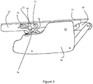
- Figure 3 shows the bonnet displacement mechanism 12 in a latched position after deployment.
- the control box 82 sends an ignition signal to the actuator 22 to fire the piston 80.
- the piston 80 engages the bonnet panel 14 exerting an upward force at the rear edge 24 thereof.
- the hinge mechanism controls the trajectory of the bonnet panel 14.
- the bonnet panel 14 moves between the normal position and the deployed position until reaching the deployed position as shown in Figure 2 .
- the shear pin 58 fails.
- the flange 20 and the hinge leaf 18 are thus separated.
- the stud 52 travels from the upper end to the lower end of the channel 56.
- the bonnet panel 14 can be moved to the latched position. This can be done by pressing down the rear edge 24 of the bonnet panel 14. In doing so the stud 52 travels back up the channel 56 to the upper end thereof. The strut 70 does not return together with the stud 52 since it has plastically deformed and remains in the deployed position. When the stud 52 reaches the upper part of the channel 56, the stud 52 deforms the resilient arm 60 so as to capture the stud 52 within the opening.
- the latch mechanism does not latch the hinge mechanism at the normal position prior to elevation since this is achieved by the shear pin 58.
- the latch mechanism does however latch the hinge mechanism at the latched position in response to moving the hinge mechanism from the deployed position back to the latched position.
- the position of the bonnet panel 14 at the normal position is not exactly the same as the position of the bonnet panel 14 at the latched position. This is because the stud 52 is mis-aligned from the opening 64 when at the normal position since the shear pin 58 holds the hinge leaf 18 and the flange 20 apart by a few millimetres. In this way, the bonnet panel 14 is a few millimetres lower in the latched position than in the normal position.
- the differences in aesthetics resulting from these arrangements signify to a user that the bonnet displacement mechanism will require attention in future. However, since there are only a few millimetres between the normal and latched positions, both positions are considered drivable positions.
- the latch mechanism is advantageous since it allows for a user to reconfigure the bonnet displacement mechanism to a drivable position, after an impact. This is in contrast to the prior art where after an impact the vehicle had to be taken to a service centre in order to re-latch the displacement mechanism.
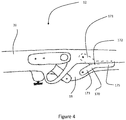
- the deformable member may include a strut 170 coupled between the flange 20 and the hinge leaf 18.
- the strut 170 is substantially V-shaped having upper 171 and lower 173 diagonal arms.
- the upper arm 171 is connected to the flange 20.
- the lower arm 173 is connected to the hinge leaf 18.
- the weakened area 172 of the strut 170 is in the form of a tear between the upper and lower arms 171 and 173.
- the strut 170 also has a tail 175 making the strut form more of a Y-shape than a V-shape.
- This tail 175 is optional and is provided to allow for an increased length of tear between the upper and lower arms 171, 173.
- the length of the tear is dictated by the tensile force which the strut 170 is designed to fracture at.
- the tensile force is defined by the upward force exerted by the actuator 22.
- the strut 170 is metallic and so any deformation is plastic deformation.
- a further embodiment describes the strut 270 in the form of an elongate rod having a weakened area 272 in the form of a kink.
- the kink is centrally arranged between opposing upper and lower arms 271, 273 of the strut 270.
- the opposing arms 271, 273 of the strut 270 are connected to the flange 20 and the hinge leaf 18.
- the weakened area 272 of the strut 270 deforms at the predetermined tensile force defined by the upward force exerted by the pyrotechnic actuator 22.
- the strut 270 is metallic and so any deformation is plastic deformation.
- an alternative embodiment describes the strut 370 as a substantially diamond shaped component.
- the diamond shaped strut 370 has a central opening forming a weakened area 372.
- the strut 370 is attached to both the flange 20 and the hinge leaf 18 at its upper and lower arm pairs 371, 373.
- the bonnet displacement mechanism 12 When the bonnet displacement mechanism 12 is deployed, the diamond shaped strut 370 collapses so as to increase in length between its opposing attachment ends. In this way, the strut 370 is plastically deformable to provide resistance to the tense load exerted by the actuator.
- the strut 370 is metallic and so any deformation is plastic deformation.
Landscapes
- Engineering & Computer Science (AREA)
- Mechanical Engineering (AREA)
- Superstructure Of Vehicle (AREA)
Description
- The invention relates to a bonnet displacement mechanism and more specifically to those mechanisms for elevating a rear edge of a bonnet panel in response to a specific frontal impact, namely a pedestrian impact.
- A typical vehicle such as a car includes a bonnet panel forming a canopy covering the engine and other related components. The bonnet panel is coupled to a body structure of the car by means of a bonnet displacement mechanism, such as a hinge. In normal use the bonnet panel is in a normal position forming a canopy over the engine and other components during normal driving. If access to the component is required, a front edge of the bonnet panel can be elevated to incline the bonnet panel about the bonnet displacement mechanism.
- Some vehicles may be fitted with a bonnet displacement mechanism which also allows a rear edge of the bonnet panel to be raised from the normal position to an elevated position. In this case, the bonnet panel is inclined in the reverse to the scenario described above. Raising the rear edge of the bonnet panel is desirable for situations such as an impact with a pedestrian. In this scenario, raising the rear edge of the bonnet panel so as to incline the bonnet panel in the reverse sense may be desirable to reduce the head impact experienced by the pedestrian.
- Such a displacement mechanism is described in
US 2007187993 A1 andEP1749711 A2 . - It is an object of the present invention to further improve on the prior art.
- Aspects of the invention are defined in the appended claims.
- According to an aspect of the present invention there is provided a bonnet displacement mechanism for coupling a bonnet panel to a body structure of a vehicle, the bonnet displacement mechanism comprising; a hinge mechanism for elevating a rear edge of the bonnet panel from a normal position, in-use, to a deployed position, and for lowering the rear edge of the bonnet panel from the deployed position to a latched position; wherein the position of the bonnet panel at said normal position is different to the bonnet at said latched position; a stud and a complimentary guide to control the elevating trajectory and the lowering trajectory of the bonnet panel; and a latch mechanism arranged to not latch the hinge mechanism in the normal position and to latch the hinge mechanism at the latched position, wherein the latch mechanism comprises a catch and a latch, wherein the catch is mis-aligned with the latch when the bonnet is in the normal position and the catch is aligned with the latch when the bonnet is in the latched position and wherein the stud forms the latch and the catch is arranged to engage and secure the stud at the latched position.
- Latching the hinge mechanism after deployment makes it possible for the vehicle to continue with ordinary use after an impact and corresponding deployment of the bonnet panel since a user can merely press down at the rear edge of the bonnet panel. This is in contrast to the aforementioned prior art whereby after deployment of the bonnet panel, the vehicle would be recovered and towed to a repair facility, or service centre to be repaired.
- Such an arrangement provides an automatic latching mechanism since the hinge latches in response to moving the latch mechanism from the deployed position to the latched position as opposed to requiring an additional operation by a user to firstly move the hinge mechanism from the deployed to the normal position and then to latch the hinge mechanism at the latched position.
- Controlling the elevating and lowering trajectories of the bonnet panel controls the vector velocities in each axis of movement. Such control further minimises head collision force experienced by a pedestrian.
- The latch mechanism may be arranged to latch the hinge mechanism at the latched position in response to the hinge mechanism being moved from the deployed position toward the normal position.
- The stud may be moveable relative to the bonnet panel and the guide is stationary relative to the bonnet panel.
- Using the stud as the latch removes the need for an additional component required for that purpose since the stud serves two functions.
- The catch may comprise an arm having an interior edge defining an opening arranged to engage the stud at the latched position, optionally wherein the arm is resilient to allow passage of the stud from the normal position to the latched position.
- A resilient arm is easy to manufacture and requires minimal maintenance after use since the arm is only a single component.
- The bonnet displacement mechanism may include a hinge leaf for elevating and lowering a front edge of the bonnet panel to and from a normal position, in use, the bonnet displacement mechanism may comprise a flange for coupling the hinge leaf to the bonnet panel.
- The guide may be provided on the flange to control the elevating trajectory and the lowering trajectory of the bonnet panel and the stud may be provided on the hinge leaf.
- Providing the stud on the hinge leaf means that the trajectory of the hinge leaf is also controlled so as to directly constrain its movement.
- The bonnet displacement mechanism may comprise a shear pin arranged to shear in dependence on the bonnet panel being moved from said normal position to said deployed position, optionally wherein the shear pin is configured to hold the hinge leaf and the flange apart from their respective latched positions.
- The bonnet displacement mechanism may comprise a deformable member arranged to deform in response to moving the hinge mechanism from the normal position to the deployed position.
- The deformable member provides a damper to damp out any oscillations caused by the sudden elevation of the rear edge of the bonnet to the deployed position. Minimising these oscillations further minimises the head impact force experienced by a pedestrian during a collision since such oscillations would change the local velocity vector of the bonnet panel. In particular, an upwards oscillation may increase the local velocity to undesirable levels.
- The deformable member may be plastically deformable.
- Plastic deformation as opposed to elastic deformation is desirable since elastic deformation may rebound the hinge leaf depending on the force applied to it. In doing so, the plastically deformable member minimises the risk of any induced oscillations in to the bonnet panel.
- The deformable member may be coupled to the bonnet panel
- The deformable member may be arranged to deform over the full travel of the bonnet panel from the normal position to the deployed position.
- Deforming the deformable member of the full travel of the bonnet panel results in maximum damping as opposed to a case where the deformable member deforms only over part of the travel of the bonnet panel, for example, the end part of the travel.
- The deformable member may be deformable in response to force exerted by the stud.
- The deformable member being deformed by the force exerted by the stud means that the stud is used for more than one purpose. In this case, the stud is used at least for engaging the guide to control the elevation of the bonnet panel and in addition for exerting force to the deformable member. Accordingly, a separate component is not required in order to initiate the damping from the deformable member.
- The deformable member may comprise a substantially U-shaped seat for receiving the stud, optionally wherein the deformable member is cantilevered from the flange and wherein the substantially U-shaped seat is provided at the suspended end thereof.
- The substantially U-shaped seat ensures that the stud positively engages the deformable member and reduces the risk of the stud slipping off or not engaging the deformable member at all.
- The deformable member may include a weakened area arranged to deform at a predetermined tensile load, optionally wherein the weakened area comprises a throat intermediate a point of cantilever from the flange and the substantially U-shaped seat, the throat being narrow relative to the point of the cantilever.
- The deformable member may comprise a strut coupled between the flange and the hinge leaf when the bonnet panel is in the normal position.
- The position of the bonnet panel at the latched position may be lower than the bonnet at the normal position.
- In this way, the position of the bonnet panel after deployment will serve as a reminder to a user that the bonnet displacement mechanism requires replacement.
- According to a further aspect of the present invention there is provided a vehicle comprising the aforementioned bonnet displacement mechanism for coupling a bonnet panel to a body structure of the vehicle.
- One or more embodiments of the invention will now be described, by way of example only, with reference to the accompanying drawings, in which:
-
Figure 1 shows a side view of a bonnet displacement mechanism according to the present invention, the mechanism being in a normal position; -
Figure 2 shows the bonnet displacement mechanism fromFigure 1 in a deployed position; -
Figure 3 shows the bonnet displacement mechanism fromFigure 2 returned to the normal position; -
Figure 4 shows a partial side view of an alternative embodiment of the bonnet displacement mechanism fromFigure 1 ; -
Figure 5 shows a similar view toFigure 4 of an alternative embodiment of the bonnet displacement mechanism; and -
Figure 6 shows a similar view toFigure 5 of an alternative embodiment of the bonnet displacement mechanism. - With reference to
Figure 1 abonnet assembly 10 includes abonnet displacement mechanism 12 and abonnet panel 14, thebonnet displacement mechanism 12 being located near the rear of thebonnet panel 14. Thebonnet displacement mechanism 12 includes amounting leaf 16, ahinge leaf 18, and aflange 20. The bonnet displacement mechanism also includes anactuator 22. - The
bonnet panel 14 is a substantially planar panel and is known in the prior art. Only part of thebonnet panel 14 is shown in the Figures for brevity. In particular, arear edge 24 of thebonnet panel 14 is shown whereas a front edge of thebonnet panel 14 is not. The function of thebonnet panel 14 is to provide a canopy to cover the engine and associated components in the front of the vehicle. - The mounting
leaf 16 is a component pressed from a single sheet of metal. The mountingleaf 16 has various contours (not shown) in order to compliment contours of a vehicle body structure so as to securely attach thebonnet displacement mechanism 12 to the body structure of the vehicle. The mountingleaf 16 has aplatform 26 formed at the front end. Theplatform 26 is formed from a bent over portion of the metal sheet from which the mountingleaf 16 is made. - With reference to
Figures 1 and2 , thehinge leaf 18 is an elongate part formed from a single piece of metal. The rear edge of thehinge leaf 18 has two connection points 28, 30 separated by a relatively short distance. The connection points 28, 30 are in the form of pivot pins. These connection points 28, 30 are used to connect thehinge leaf 18 to the mountingleaf 16 by thefront arm 32 and therear arm 34 respectively. Although not shown, since it is covered by the mountingleaf 16, thefront arm 32 is constructed from two beams which have a joint connection between them. The lower beam is connected to the mountingleaf 16 towards the forward end thereof. Therear arm 34 is connected to the mountingleaf 16 towards a rear end thereof. In this way, the mountingleaf 16 has afront coupling point 36 and arear coupling point 38 on the mountingleaf 16. The separation distance between the front and rear coupling points 36, 38 is relatively large. The distance between the front and rear coupling points 36, 38 is greater than the distance between the front and rear connection points 28, 30. It is thus possible to incline thehinge leaf 18 relative to the mountingleaf 16 by virtue of the kinematic arrangement provided by thefront arm 32 being jointed, therear arm 34 being a single beam and the connection points 28 and 30 having a smaller separation distance than the coupling points 36, 38. In this way, the front end of thebonnet panel 14 can be elevated to and from the normal position when access to the engine or other components is required. - The front end of the
hinge leaf 18 includes a longitudinal slot extending generally in the direction of thehinge leaf 18. This slot is not shown in the Figures due to the extent of coverage by theflange 20. The slot is co-operable with ascrew 40 attached to theflange 20 so as to provide a sliding arrangement between thehinge leaf 18 and theflange 20. - The
hinge leaf 18 also includes a downwardly facingnose 42. Thenose 42 provides an attachment point for abolt 44. Thebolt 44 is arranged to engage theplatform 26 to support thebonnet panel 14 during normal operation of the vehicle. Thehinge leaf 18 also forms anattachment point 46 in the form of a pin. Theattachment point 46 attaches one end of abar 48 to thehinge leaf 18. The other end of thebar 48 is attached to theflange 20 by asecond attachment point 50. Thebar 48 is pivotable about the first and second attachment points 46, 50. The attachment points 46, 50 and thebar 48, together with thescrew 40 being slidable within the slot (not shown), combine to form a hinge mechanism, as will be described in more detail below. - The hinge mechanism can elevate the
rear edge 24 of thebonnet panel 14 from a normal position as shown inFigure 1 , to a deployed position, as shown inFigure 2 . In addition, the hinge mechanism can lower therear edge 24 of thebonnet panel 14 from the deployed position as shown inFigure 2 , to a latched position as shown inFigure 3 . As will be described in more detail below, the normal position of thebonnet panel 14 is not exactly the same as the latched position of thebonnet panel 14. - The
hinge leaf 18 also includes astud 52. Thestud 52 extends generally horizontally away from thehinge leaf 18. - The
flange 20 forms an inverted L shape in section having a substantially vertical wall and a substantially horizontal top. Thebonnet panel 14 is attached to the top. The vertical wall of theflange 20 has a downwardly projectingportion 54. This downwardly projectingportion 54 accommodates a curvilinear cut away portion in the form of achannel 56. Thechannel 56 forms a complimentary guide for accommodating thestud 52. Thestud 52 and the complimentary guide control the elevating trajectory and the lowering trajectory of thebonnet panel 14. Since thestud 52 is attached to thehinge leaf 18 and the guide is provided on theflange 20, thestud 52 is movable relative to thebonnet panel 14 and the guide is stationary relative to thebonnet panel 14. When in the normal position (Figure 1 ), thestud 52 abuts an upper edge of thechannel 56. When in a deployed position (Figure 2 ), thestud 52 abuts a lower edge of thechannel 56. - A
shear pin 58 attaches thehinge leaf 18 to theflange 20 when thebonnet panel 14 is at the normal position. Theshear pin 58 is configured in terms of material composition and dimensions to shear at a predetermined separation force. The predetermined separation force is dictated by the force exerted on thebonnet panel 14 by theactuator 22 as described in further detail below. Once theshear pin 58 has failed, thepin 58 is separated into two parts. - The
bonnet displacement mechanism 12 also includes a latch mechanism. The latch mechanism includes an elongateresilient arm 60. Theresilient arm 60 is metallic. Theresilient arm 60 is made from steel. Theresilient arm 60 is connected to the vertical wall of theflange 20 by thesecond attachment point 50 and astabilising point 62. Thestabilising point 62 is in the form of a bolt or screw. Theresilient arm 60 also has at its other end, an interior edge defining an opening 64 (Figure 2 ). Theopening 64 is dimensioned so as to engage thestud 52 when aligned therewith. In this way, theopening 64 can provide a catch and thestud 52 can form a complimentary latch where theresilient arm 60 secures thestud 52 when thestud 52 is aligned with theopening 64. Thestud 52 is aligned with theopening 64 and caught thereby when at the latched position but not at the normal position since thestud 52 andopening 64 are not aligned at the normal position. - Still with reference to
Figures 1 and2 , thebonnet displacement mechanism 12 also includes a deformable member in the form of astrut 70. Thestrut 70 is connected at one end to the vertical wall of theflange 20 by the same connection point as theresilient arm 60. Namely, thesecond attachment point 50 and thestabilising point 62. In this way, thestrut 70 is cantilevered from theflange 20. Thestrut 70 forms a deformable member since it has a weakenedarea 72 in the form of a throat at the middle, which is relatively narrow compared to the point of connection to the flange. This throat is dimensioned to deform at a predetermined tensile load. At a suspended end of thestrut 70, opposite the connection points 50, 62, thestrut 70 has two upstanding legs forming a substantiallyU-shaped seat 74. The substantiallyU-shaped seat 74 is dimensioned and configured so as to receive thestud 52. Thestrut 70 is made from a single piece of pressed metal. In this way, thestrut 70 is plastically deformable. Specifically, thestrut 70 is deformable when the hinge mechanism is moved from the normal position (Figure 1 ) to the deployed position (Figure 2 ). At the normal position (Figure 1 ) the throat is straight and at the deployed position (Figure 2 ) the throat is bent forming an elbow. In this way, a simple visual inspection can determine whether or not the deformable member has deformed. - The
stud 52 is the component which deforms thestrut 70. This is because thestud 52 is connected to thehinge leaf 18 and moves relative to theflange 20 and so exerts a force on theseat 74 of the deformable member during relative travel of thestud 52. Since thestud 52 is in direct contact with theU-shaped seat 74 when in the normal position (Figure 1 ), thestrut 70 is arranged to deform over the full length of travel of thebonnet panel 14 from the normal position (Figure 1 ) to the deployed position (Figure 2 ). - The
resilient arm 60 includes an arch 61 on its lower edge and is substantially parallel with the vertical wall of theflange 20. In addition, theresilient arm 60 is bent away from theflange 20. In this way, theresilient arm 60 allows the deformable member to pass intermediate theresilient arm 60 and theflange 20 at its suspended end. In this way, the U-shaped seat contacts thestud 52 in the normal position. - In the normal position, the
stud 52 is not aligned with theopening 64. Instead, thestud 52 is in contact with theresilient arm 60 to deflect the suspended end of thearm 60 away from theflange 20 from a neutral position to a deflected position. Theopening 64 thus does not form a catch to catch thestud 52 at the normal position of thebonnet panel 14. - The
resilient arm 60 returns to the neutral position when thestud 52 has moved far enough down thechannel 56 and is no longer in contact with thearm 60. Thestud 52 deflects the resilient arm from the neutral position to the deflected position when contact re-occurs when moving thebonnet panel 14 from the deployed position (figure 2 ) to a latched position (figure 3 ). The latched position will be described in more detail below. - The
actuator 22 is a pyrotechnic actuator. Thepyrotechnic actuator 22 is connected to the mountingleaf 16. Thepyrotechnic actuator 22 has apiston 80 at its vertical end and acontrol box 82 at the lower end. Thepiston 80 is positioned directly beneath thebonnet panel 14. Thecontrol box 82 is connected to a sensor by awire 84. The sensor is in the form of an optical fibre pressure sensor arranged at a front end of the vehicle in order to detect pressure impulses indicative of the vehicle's impact with a pedestrian. Theactuator 22 and the sensor (not shown) are known in the art and are described in no further detail here. - Operation of the
bonnet displacement mechanism 12 is best described with reference toFigure 1 to 3 .Figure 1 shows thebonnet displacement mechanism 12 in a normal position, in use.Figure 2 shows thebonnet displacement mechanism 12 in a deployed position.Figure 3 shows thebonnet displacement mechanism 12 in a latched position after deployment. - With reference to
Figure 1 , upon the sensor (not shown) detecting an impulse indicative of a pedestrian strike, thecontrol box 82 sends an ignition signal to theactuator 22 to fire thepiston 80. Thepiston 80 engages thebonnet panel 14 exerting an upward force at therear edge 24 thereof. The hinge mechanism controls the trajectory of thebonnet panel 14. Thebonnet panel 14 moves between the normal position and the deployed position until reaching the deployed position as shown inFigure 2 . - In response to the force exerted on the
bonnet panel 14 by theactuator 22 firing, theshear pin 58 fails. Theflange 20 and thehinge leaf 18 are thus separated. Thestud 52 travels from the upper end to the lower end of thechannel 56. - As the
stud 52 moves down thechannel 56, the weakenedarea 72 of thestrut 70 plastically deforms as shown inFigure 2 . Thebonnet panel 14 comes to rest at the deployed position when thestud 52 reaches the lower end of thechannel 56. During transit, thestud 52 releases theresilient arm 60 and allows it to return to the neutral position. - With reference to
Figure 3 , after deployment, thebonnet panel 14 can be moved to the latched position. This can be done by pressing down therear edge 24 of thebonnet panel 14. In doing so thestud 52 travels back up thechannel 56 to the upper end thereof. Thestrut 70 does not return together with thestud 52 since it has plastically deformed and remains in the deployed position. When thestud 52 reaches the upper part of thechannel 56, thestud 52 deforms theresilient arm 60 so as to capture thestud 52 within the opening. - At this point, it will be appreciated that the latch mechanism does not latch the hinge mechanism at the normal position prior to elevation since this is achieved by the
shear pin 58. The latch mechanism does however latch the hinge mechanism at the latched position in response to moving the hinge mechanism from the deployed position back to the latched position. - The position of the
bonnet panel 14 at the normal position is not exactly the same as the position of thebonnet panel 14 at the latched position. This is because thestud 52 is mis-aligned from theopening 64 when at the normal position since theshear pin 58 holds thehinge leaf 18 and theflange 20 apart by a few millimetres. In this way, thebonnet panel 14 is a few millimetres lower in the latched position than in the normal position. The differences in aesthetics resulting from these arrangements signify to a user that the bonnet displacement mechanism will require attention in future. However, since there are only a few millimetres between the normal and latched positions, both positions are considered drivable positions. - The latch mechanism is advantageous since it allows for a user to reconfigure the bonnet displacement mechanism to a drivable position, after an impact. This is in contrast to the prior art where after an impact the vehicle had to be taken to a service centre in order to re-latch the displacement mechanism.
- Various alternative embodiments are envisaged without departing from the scope of the claims. In particular, various modifications may be made to components such as the deformable member. Some of those alternatives will now be described. However, not all of features common with the aforementioned embodiment will be replicated below for brevity.
- With reference to
Figure 4 , the deformable member may include astrut 170 coupled between theflange 20 and thehinge leaf 18. Thestrut 170 is substantially V-shaped having upper 171 and lower 173 diagonal arms. Theupper arm 171 is connected to theflange 20. Thelower arm 173 is connected to thehinge leaf 18. The weakenedarea 172 of thestrut 170 is in the form of a tear between the upper andlower arms bonnet displacement mechanism 12 deploys, thebonnet panel 14 moves from the normal position to the deployed position, the upper andlower arms strut 170. Thestrut 170 also has atail 175 making the strut form more of a Y-shape than a V-shape. Thistail 175 is optional and is provided to allow for an increased length of tear between the upper andlower arms strut 170 is designed to fracture at. The tensile force is defined by the upward force exerted by theactuator 22. Thestrut 170 is metallic and so any deformation is plastic deformation. - With reference to
Figure 5 , a further embodiment describes thestrut 270 in the form of an elongate rod having a weakenedarea 272 in the form of a kink. The kink is centrally arranged between opposing upper andlower arms strut 270. The opposingarms strut 270 are connected to theflange 20 and thehinge leaf 18. Upon deployment of thebonnet displacement mechanism 12, the weakenedarea 272 of thestrut 270 deforms at the predetermined tensile force defined by the upward force exerted by thepyrotechnic actuator 22. Thestrut 270 is metallic and so any deformation is plastic deformation. - With reference to
Figure 6 , an alternative embodiment describes thestrut 370 as a substantially diamond shaped component. The diamond shapedstrut 370 has a central opening forming a weakenedarea 372. Thestrut 370 is attached to both theflange 20 and thehinge leaf 18 at its upper and lower arm pairs 371, 373. When thebonnet displacement mechanism 12 is deployed, the diamond shapedstrut 370 collapses so as to increase in length between its opposing attachment ends. In this way, thestrut 370 is plastically deformable to provide resistance to the tense load exerted by the actuator. Thestrut 370 is metallic and so any deformation is plastic deformation.
Claims (15)
- A bonnet displacement mechanism (12) for coupling a bonnet panel (14) to a body structure of a vehicle, the bonnet displacement mechanism (12) comprising;
a hinge mechanism for elevating a rear edge (24) of the bonnet panel (14) from a normal position, in-use, to a deployed position, and for lowering the rear edge (24) of the bonnet panel (14) from the deployed position to a latched position wherein the position of the bonnet panel (14) at said normal position is different to the bonnet (14) at said latched position;
a stud (52) and a complimentary guide for guiding the stud to control the elevating trajectory and the lowering trajectory of the bonnet panel (14); and
a latch mechanism arranged to not latch the hinge mechanism in the normal position and to latch the hinge mechanism at the latched position,
wherein the latch mechanism comprises a catch and a latch, wherein the catch is mis-aligned with the latch when the bonnet (14) is in the normal position and the catch is aligned with the latch when the bonnet (14) is in the latched position and wherein the stud (52) forms the latch and the catch is arranged to engage and secure the stud (52) at the latched position. - The bonnet displacement mechanism (12) of claim 1 wherein the latch mechanism is arranged to latch the hinge mechanism at the latched position in response to the hinge mechanism being moved from the deployed position toward the normal position.
- The bonnet displacement mechanism (12) of claim 1 or claim 2 wherein the stud (52) is moveable relative to the bonnet panel (14) and the guide is stationary relative to the bonnet panel (14).
- The bonnet displacement mechanism (12) of any one of the preceding claims wherein the catch comprises an arm (60) having an interior edge defining an opening (64) arranged to engage the stud (52) at the latched position, optionally wherein the arm (60) is resilient to allow passage of the stud (52) from the normal position to the latched position.
- The bonnet displacement mechanism (12) of any preceding claim including a hinge leaf (18) for elevating and lowering a front edge of the bonnet panel (14) to and from a normal position, in-use, the bonnet displacement mechanism (12) comprising a flange (20) for coupling the hinge leaf (18) to the bonnet panel (14).
- The bonnet displacement mechanism (12) of claim 5, wherein the guide is provided on the flange (20) to control the elevating trajectory and the lowering trajectory of the bonnet panel (14) and the stud is provided on the hinge leaf (18).
- The bonnet displacement mechanism (12) of any preceding claim, comprising a shear pin (58) arranged to shear in dependence on the bonnet panel (14) being moved from said normal position to said deployed position, optionally wherein the shear pin (58) is configured to hold the hinge leaf (18) and the flange (20) apart from their respective latched positions.
- The bonnet displacement mechanism (12) of any preceding claim comprising a deformable member arranged to deform in response to moving the hinge mechanism from the normal position to the deployed position.
- The bonnet displacement mechanism (12) of claim 8 wherein the deformable member is plastically deformable and/or wherein the deformable member is coupled to the bonnet panel (14) and/or wherein the deformable member is arranged to deform over the full travel of the bonnet panel (14) from the normal position to the deployed position.
- The bonnet displacement mechanism (12) of claim 8 or claim 9, wherein the deformable member is deformable in response to a force exerted by the stud (52).
- The bonnet displacement mechanism (12) of claim 10 wherein the deformable member comprises a substantially U-shaped seat for receiving the stud (52), optionally wherein the deformable member is cantilevered from the flange (20) and wherein the substantially U-shaped seat is provided at the suspended end thereof.
- The bonnet displacement mechanism (12) of claim 11, wherein the deformable member includes a weakened area (72) arranged to deform at a predetermined tensile load, optionally wherein the weakened area (72) comprises a throat intermediate a point of cantilever from the flange (20) and the substantially U-shaped seat, the throat being narrow relative to the point of the cantilever.
- The bonnet displacement mechanism (12) of any one of claims 8 to 12, wherein the deformable member includes a strut (70) coupled between the flange (20) and the hinge leaf (18) when the bonnet panel (14) is in the normal position.
- The bonnet displacement mechanism (12) of any preceding claim wherein the position of the bonnet panel (14) at the latched position is lower than the bonnet (14) at the normal position.
- A vehicle comprising a bonnet displacement mechanism (12) of any preceding claim for coupling a bonnet panel (14) to a body structure of the vehicle.
Priority Applications (1)
| Application Number | Priority Date | Filing Date | Title |
|---|---|---|---|
| EP18183295.7A EP3418130B1 (en) | 2014-09-05 | 2015-09-04 | Bonnet displacement mechanism |
Applications Claiming Priority (3)
| Application Number | Priority Date | Filing Date | Title |
|---|---|---|---|
| GBGB1415721.8A GB201415721D0 (en) | 2014-09-05 | 2014-09-05 | Bonnet displacement mechanism |
| GBGB1415723.4A GB201415723D0 (en) | 2014-09-05 | 2014-09-05 | Bonnet displacement mechanism |
| PCT/EP2015/070294 WO2016034725A1 (en) | 2014-09-05 | 2015-09-04 | Bonnet displacement mechanism |
Related Child Applications (2)
| Application Number | Title | Priority Date | Filing Date |
|---|---|---|---|
| EP18183295.7A Division EP3418130B1 (en) | 2014-09-05 | 2015-09-04 | Bonnet displacement mechanism |
| EP18183295.7A Division-Into EP3418130B1 (en) | 2014-09-05 | 2015-09-04 | Bonnet displacement mechanism |
Publications (2)
| Publication Number | Publication Date |
|---|---|
| EP3188935A1 EP3188935A1 (en) | 2017-07-12 |
| EP3188935B1 true EP3188935B1 (en) | 2018-11-21 |
Family
ID=54062750
Family Applications (2)
| Application Number | Title | Priority Date | Filing Date |
|---|---|---|---|
| EP18183295.7A Active EP3418130B1 (en) | 2014-09-05 | 2015-09-04 | Bonnet displacement mechanism |
| EP15759463.1A Active EP3188935B1 (en) | 2014-09-05 | 2015-09-04 | Bonnet displacement mechanism |
Family Applications Before (1)
| Application Number | Title | Priority Date | Filing Date |
|---|---|---|---|
| EP18183295.7A Active EP3418130B1 (en) | 2014-09-05 | 2015-09-04 | Bonnet displacement mechanism |
Country Status (5)
| Country | Link |
|---|---|
| US (1) | US10369959B2 (en) |
| EP (2) | EP3418130B1 (en) |
| CN (1) | CN106794818A (en) |
| GB (2) | GB2548771B (en) |
| WO (1) | WO2016034725A1 (en) |
Families Citing this family (26)
| Publication number | Priority date | Publication date | Assignee | Title |
|---|---|---|---|---|
| DE102014015998A1 (en) * | 2014-10-29 | 2016-05-04 | Audi Ag | Motor vehicle, comprising a front flap which is pivotally mounted on two hinges on a body |
| KR101743012B1 (en) * | 2016-03-28 | 2017-06-05 | 평화정공 주식회사 | Lift device for active hood |
| DE102016113684B4 (en) * | 2016-07-25 | 2024-05-23 | Dr. Ing. H.C. F. Porsche Aktiengesellschaft | Hinge device with an integrated pedestrian protection for a front hood |
| DE102016215377B4 (en) * | 2016-08-17 | 2024-04-25 | Bayerische Motoren Werke Aktiengesellschaft | HINGE ARRANGEMENT |
| US10315612B2 (en) * | 2016-08-24 | 2019-06-11 | Honda Motor Co., Ltd. | Vehicle hood lift system |
| US10100565B2 (en) * | 2016-12-22 | 2018-10-16 | GM Global Technology Operations LLC | Active hood hinge with upstop |
| DE102017122573A1 (en) * | 2017-09-28 | 2019-03-28 | Kiekert Ag | Locking device for a moving part of a vehicle |
| CN107878571B (en) * | 2017-10-30 | 2021-03-02 | 江苏锦恒汽车安全系统有限公司 | Hinge mechanism of automobile engine compartment cover and method for protecting head of pedestrian by using hinge mechanism |
| USD961486S1 (en) * | 2018-05-21 | 2022-08-23 | Ringbrothers, Llc | Automobile hood hinge |
| CN109025586A (en) * | 2018-09-11 | 2018-12-18 | 吉利汽车研究院(宁波)有限公司 | A kind of hood hinge for vehicle |
| KR102598536B1 (en) * | 2018-10-05 | 2023-11-03 | 현대자동차주식회사 | Always Operation Apparatus for Active Hood linked with ADAS |
| US11383672B2 (en) * | 2018-11-27 | 2022-07-12 | Magna Closures Inc. | Active pedestrian hood hinge with integrated latch assembly |
| USD921558S1 (en) | 2019-03-08 | 2021-06-08 | Ringbrothers Llc | Automobile hood hinge |
| USD921559S1 (en) | 2019-03-08 | 2021-06-08 | Ringbrothers Llc | Automobile hood hinge |
| JP7143237B2 (en) * | 2019-03-11 | 2022-09-28 | 本田技研工業株式会社 | Hood pop-up structure |
| EP4051543B1 (en) * | 2019-10-28 | 2023-09-20 | PSA Automobiles SA | Active hinge for motor vehicle bonnet |
| USD945349S1 (en) | 2020-04-22 | 2022-03-08 | Ringbrothers, Llc | Automobile hood hinge |
| USD944714S1 (en) | 2020-04-22 | 2022-03-01 | Ringbrothers, Llc | Automobile hood hinge |
| USD944715S1 (en) | 2020-08-26 | 2022-03-01 | Ringbrothers, Llc | Automobile hood hinge |
| DE102021205306B4 (en) | 2021-05-25 | 2025-08-07 | Bayerische Motoren Werke Aktiengesellschaft | PEDESTRIAN PROTECTION VEHICLE HINGE |
| USD1004516S1 (en) * | 2021-09-30 | 2023-11-14 | Ringbrothers, Llc | Automobile hood hinge |
| USD998531S1 (en) * | 2021-11-03 | 2023-09-12 | Ringbrothers, Llc | Automobile hood hinge |
| DE102022116438A1 (en) * | 2022-07-01 | 2024-01-04 | Bayerische Motoren Werke Aktiengesellschaft | Front lid hinge for a motor vehicle and motor vehicle with such a front lid hinge |
| US12077126B2 (en) * | 2022-07-05 | 2024-09-03 | Hyundai Motor Company | Active hood system |
| USD1042296S1 (en) | 2023-05-12 | 2024-09-17 | Ringbrothers Llc | Automobile hood hinge |
| US12416188B2 (en) * | 2023-10-30 | 2025-09-16 | Pha Co., Ltd. | Active hood hinge for vehicle |
Family Cites Families (19)
| Publication number | Priority date | Publication date | Assignee | Title |
|---|---|---|---|---|
| US6414882B1 (en) * | 2001-08-30 | 2002-07-02 | Micron Technology, Inc. | Low voltage charge pump apparatus and method |
| GB0121523D0 (en) | 2001-09-06 | 2001-10-24 | Itw Ltd | Hinge assembly |
| DE20215380U1 (en) * | 2002-10-07 | 2003-02-13 | TRW Occupant Restraint Systems GmbH & Co. KG, 73553 Alfdorf | hood hinge |
| FR2864936B1 (en) | 2004-01-14 | 2008-08-15 | Pyroalliance | ACTUATOR HOOD LIFT WITH HOOK LATCH SYSTEM. |
| GB2410924B (en) * | 2004-02-14 | 2007-04-11 | Ford Global Tech Llc | A hinge arrangement |
| DE102004037320A1 (en) * | 2004-08-02 | 2006-03-16 | Trw Automotive Gmbh | Device for lifting a body part of a motor vehicle and method for operating such a device |
| GB2428644B (en) | 2005-08-02 | 2009-04-29 | Ford Global Tech Llc | A motor vehicle |
| CA2518682A1 (en) * | 2005-09-09 | 2007-03-09 | Multimatic Inc. | Pedestrian protection hood hinge |
| JP4941401B2 (en) * | 2008-04-28 | 2012-05-30 | 豊田合成株式会社 | Actuator |
| US8534410B2 (en) * | 2009-03-31 | 2013-09-17 | Mazda Motor Corporation | Pedestrian protection device for vehicle |
| DE102009040415B4 (en) * | 2009-09-07 | 2020-08-06 | Bayerische Motoren Werke Aktiengesellschaft | Vehicle safety device with a first and a second hinge part |
| DE102009040413A1 (en) * | 2009-09-07 | 2011-03-10 | Bayerische Motoren Werke Aktiengesellschaft | Safety mechanism for lifting e.g. front flap of outer shell of vehicle during person collision, has hinge for guidance of component, and coupling arranged between upper hinge upper part and lower hinge upper part by connecting device |
| EP2364887B1 (en) | 2010-03-08 | 2019-04-10 | Flexngate Automotive Iberica, S.A. | Safety system applicable to automobiles for the protection of a pedestrian in the event of being hit |
| DE102010023976B4 (en) | 2010-06-16 | 2016-10-06 | Daimler Ag | Hinge for a bonnet of a motor vehicle |
| US9121212B2 (en) | 2013-03-15 | 2015-09-01 | Dura Operating, Llc | Releasable hood hinge with positive reset |
| KR101510011B1 (en) * | 2013-12-17 | 2015-04-07 | 현대자동차주식회사 | Active hood hinge apparatus for vehicle |
| JP5907182B2 (en) * | 2014-01-20 | 2016-04-26 | トヨタ自動車株式会社 | Pop-up hood device for vehicle |
| US9701277B2 (en) * | 2015-02-25 | 2017-07-11 | Magna Closures Inc. | Active hinge with deployed position latch |
| US10100565B2 (en) * | 2016-12-22 | 2018-10-16 | GM Global Technology Operations LLC | Active hood hinge with upstop |
-
2015
- 2015-09-04 EP EP18183295.7A patent/EP3418130B1/en active Active
- 2015-09-04 EP EP15759463.1A patent/EP3188935B1/en active Active
- 2015-09-04 GB GB1710751.7A patent/GB2548771B/en active Active
- 2015-09-04 WO PCT/EP2015/070294 patent/WO2016034725A1/en not_active Ceased
- 2015-09-04 CN CN201580047205.8A patent/CN106794818A/en active Pending
- 2015-09-04 US US15/508,856 patent/US10369959B2/en active Active
- 2015-09-04 GB GB1515709.2A patent/GB2529940B/en active Active
Non-Patent Citations (1)
| Title |
|---|
| None * |
Also Published As
| Publication number | Publication date |
|---|---|
| EP3418130B1 (en) | 2020-03-25 |
| GB2548771B (en) | 2018-08-22 |
| EP3188935A1 (en) | 2017-07-12 |
| GB201515709D0 (en) | 2015-10-21 |
| US10369959B2 (en) | 2019-08-06 |
| CN106794818A (en) | 2017-05-31 |
| GB201710751D0 (en) | 2017-08-16 |
| GB2529940A (en) | 2016-03-09 |
| GB2529940B (en) | 2017-08-16 |
| GB2548771A (en) | 2017-09-27 |
| US20170259776A1 (en) | 2017-09-14 |
| EP3418130A1 (en) | 2018-12-26 |
| WO2016034725A1 (en) | 2016-03-10 |
Similar Documents
| Publication | Publication Date | Title |
|---|---|---|
| US10369959B2 (en) | Bonnet displacement mechanism | |
| US7934293B2 (en) | Hinge mechanism | |
| CN105986711B (en) | Passive hood hinges for vehicles | |
| CN103291158B (en) | Linkage | |
| EP2777992B1 (en) | Releasable hood hinge with positive reset | |
| US20190061679A1 (en) | Hood hinge for a front hood of a vehicle having movable support of a lifting actuator | |
| US20140359974A1 (en) | Hinge device for the articulated attachment of a hood to a vehicle chassis | |
| US10384638B2 (en) | Hood hinge for a motor vehicle | |
| JP2009527407A (en) | Truck with cab front mount | |
| EP2495140A1 (en) | Hood hinge assembly for a motor vehicle | |
| CN111465531B (en) | A device for hanging lights in vehicles | |
| EP2894053B1 (en) | Open roof construction for a vehicle and wind deflector for use therein | |
| EP3393862B1 (en) | Bumper | |
| GB2451622A (en) | Bonnet hinge mechanism | |
| US8490735B2 (en) | Vehicle hood structure for pedestrian body impact protection | |
| JP2012081843A (en) | Vehicular hood flip-up device | |
| CN102933411A (en) | Vehicle door having a multifunction carrier | |
| EP3323683A1 (en) | Hinge arrangement | |
| EP2106976B1 (en) | Hood hinge | |
| CN110630125A (en) | Active pedestrian protection front cover hinge system | |
| EP3184377A1 (en) | Hinge arrangement | |
| EP2423056B1 (en) | A safety device | |
| KR20160129233A (en) | active hinges operation structure for automobile | |
| CN108137098A (en) | The structure member of motor vehicles and the front lower portion section including the component | |
| CN114981129B (en) | Active hinge for motor vehicle hood |
Legal Events
| Date | Code | Title | Description |
|---|---|---|---|
| STAA | Information on the status of an ep patent application or granted ep patent |
Free format text: STATUS: THE INTERNATIONAL PUBLICATION HAS BEEN MADE |
|
| PUAI | Public reference made under article 153(3) epc to a published international application that has entered the european phase |
Free format text: ORIGINAL CODE: 0009012 |
|
| STAA | Information on the status of an ep patent application or granted ep patent |
Free format text: STATUS: REQUEST FOR EXAMINATION WAS MADE |
|
| 17P | Request for examination filed |
Effective date: 20170405 |
|
| AK | Designated contracting states |
Kind code of ref document: A1 Designated state(s): AL AT BE BG CH CY CZ DE DK EE ES FI FR GB GR HR HU IE IS IT LI LT LU LV MC MK MT NL NO PL PT RO RS SE SI SK SM TR |
|
| AX | Request for extension of the european patent |
Extension state: BA ME |
|
| DAV | Request for validation of the european patent (deleted) | ||
| DAX | Request for extension of the european patent (deleted) | ||
| GRAP | Despatch of communication of intention to grant a patent |
Free format text: ORIGINAL CODE: EPIDOSNIGR1 |
|
| STAA | Information on the status of an ep patent application or granted ep patent |
Free format text: STATUS: GRANT OF PATENT IS INTENDED |
|
| INTG | Intention to grant announced |
Effective date: 20180503 |
|
| GRAS | Grant fee paid |
Free format text: ORIGINAL CODE: EPIDOSNIGR3 |
|
| RBV | Designated contracting states (corrected) |
Designated state(s): AL AT BE BG CH CY CZ DE DK EE ES FI FR GR HR HU IE IS IT LI LT LU LV MC MK MT NL NO PL PT RO RS SE SI SK SM TR |
|
| GRAA | (expected) grant |
Free format text: ORIGINAL CODE: 0009210 |
|
| STAA | Information on the status of an ep patent application or granted ep patent |
Free format text: STATUS: THE PATENT HAS BEEN GRANTED |
|
| AK | Designated contracting states |
Kind code of ref document: B1 Designated state(s): AL AT BE BG CH CY CZ DE DK EE ES FI FR GR HR HU IE IS IT LI LT LU LV MC MK MT NL NO PL PT RO RS SE SI SK SM TR |
|
| REG | Reference to a national code |
Ref country code: CH Ref legal event code: EP |
|
| REG | Reference to a national code |
Ref country code: IE Ref legal event code: FG4D |
|
| REG | Reference to a national code |
Ref country code: DE Ref legal event code: R096 Ref document number: 602015020061 Country of ref document: DE |
|
| REG | Reference to a national code |
Ref country code: AT Ref legal event code: REF Ref document number: 1067173 Country of ref document: AT Kind code of ref document: T Effective date: 20181215 |
|
| REG | Reference to a national code |
Ref country code: NL Ref legal event code: MP Effective date: 20181121 |
|
| REG | Reference to a national code |
Ref country code: AT Ref legal event code: MK05 Ref document number: 1067173 Country of ref document: AT Kind code of ref document: T Effective date: 20181121 |
|
| PG25 | Lapsed in a contracting state [announced via postgrant information from national office to epo] |
Ref country code: FI Free format text: LAPSE BECAUSE OF FAILURE TO SUBMIT A TRANSLATION OF THE DESCRIPTION OR TO PAY THE FEE WITHIN THE PRESCRIBED TIME-LIMIT Effective date: 20181121 Ref country code: NO Free format text: LAPSE BECAUSE OF FAILURE TO SUBMIT A TRANSLATION OF THE DESCRIPTION OR TO PAY THE FEE WITHIN THE PRESCRIBED TIME-LIMIT Effective date: 20190221 Ref country code: IS Free format text: LAPSE BECAUSE OF FAILURE TO SUBMIT A TRANSLATION OF THE DESCRIPTION OR TO PAY THE FEE WITHIN THE PRESCRIBED TIME-LIMIT Effective date: 20190321 Ref country code: LV Free format text: LAPSE BECAUSE OF FAILURE TO SUBMIT A TRANSLATION OF THE DESCRIPTION OR TO PAY THE FEE WITHIN THE PRESCRIBED TIME-LIMIT Effective date: 20181121 Ref country code: AT Free format text: LAPSE BECAUSE OF FAILURE TO SUBMIT A TRANSLATION OF THE DESCRIPTION OR TO PAY THE FEE WITHIN THE PRESCRIBED TIME-LIMIT Effective date: 20181121 Ref country code: ES Free format text: LAPSE BECAUSE OF FAILURE TO SUBMIT A TRANSLATION OF THE DESCRIPTION OR TO PAY THE FEE WITHIN THE PRESCRIBED TIME-LIMIT Effective date: 20181121 Ref country code: LT Free format text: LAPSE BECAUSE OF FAILURE TO SUBMIT A TRANSLATION OF THE DESCRIPTION OR TO PAY THE FEE WITHIN THE PRESCRIBED TIME-LIMIT Effective date: 20181121 Ref country code: BG Free format text: LAPSE BECAUSE OF FAILURE TO SUBMIT A TRANSLATION OF THE DESCRIPTION OR TO PAY THE FEE WITHIN THE PRESCRIBED TIME-LIMIT Effective date: 20190221 Ref country code: HR Free format text: LAPSE BECAUSE OF FAILURE TO SUBMIT A TRANSLATION OF THE DESCRIPTION OR TO PAY THE FEE WITHIN THE PRESCRIBED TIME-LIMIT Effective date: 20181121 |
|
| PG25 | Lapsed in a contracting state [announced via postgrant information from national office to epo] |
Ref country code: PT Free format text: LAPSE BECAUSE OF FAILURE TO SUBMIT A TRANSLATION OF THE DESCRIPTION OR TO PAY THE FEE WITHIN THE PRESCRIBED TIME-LIMIT Effective date: 20190321 Ref country code: AL Free format text: LAPSE BECAUSE OF FAILURE TO SUBMIT A TRANSLATION OF THE DESCRIPTION OR TO PAY THE FEE WITHIN THE PRESCRIBED TIME-LIMIT Effective date: 20181121 Ref country code: SE Free format text: LAPSE BECAUSE OF FAILURE TO SUBMIT A TRANSLATION OF THE DESCRIPTION OR TO PAY THE FEE WITHIN THE PRESCRIBED TIME-LIMIT Effective date: 20181121 Ref country code: RS Free format text: LAPSE BECAUSE OF FAILURE TO SUBMIT A TRANSLATION OF THE DESCRIPTION OR TO PAY THE FEE WITHIN THE PRESCRIBED TIME-LIMIT Effective date: 20181121 Ref country code: NL Free format text: LAPSE BECAUSE OF FAILURE TO SUBMIT A TRANSLATION OF THE DESCRIPTION OR TO PAY THE FEE WITHIN THE PRESCRIBED TIME-LIMIT Effective date: 20181121 Ref country code: GR Free format text: LAPSE BECAUSE OF FAILURE TO SUBMIT A TRANSLATION OF THE DESCRIPTION OR TO PAY THE FEE WITHIN THE PRESCRIBED TIME-LIMIT Effective date: 20190222 |
|
| PG25 | Lapsed in a contracting state [announced via postgrant information from national office to epo] |
Ref country code: IT Free format text: LAPSE BECAUSE OF FAILURE TO SUBMIT A TRANSLATION OF THE DESCRIPTION OR TO PAY THE FEE WITHIN THE PRESCRIBED TIME-LIMIT Effective date: 20181121 Ref country code: CZ Free format text: LAPSE BECAUSE OF FAILURE TO SUBMIT A TRANSLATION OF THE DESCRIPTION OR TO PAY THE FEE WITHIN THE PRESCRIBED TIME-LIMIT Effective date: 20181121 Ref country code: PL Free format text: LAPSE BECAUSE OF FAILURE TO SUBMIT A TRANSLATION OF THE DESCRIPTION OR TO PAY THE FEE WITHIN THE PRESCRIBED TIME-LIMIT Effective date: 20181121 Ref country code: DK Free format text: LAPSE BECAUSE OF FAILURE TO SUBMIT A TRANSLATION OF THE DESCRIPTION OR TO PAY THE FEE WITHIN THE PRESCRIBED TIME-LIMIT Effective date: 20181121 |
|
| REG | Reference to a national code |
Ref country code: DE Ref legal event code: R097 Ref document number: 602015020061 Country of ref document: DE |
|
| PG25 | Lapsed in a contracting state [announced via postgrant information from national office to epo] |
Ref country code: EE Free format text: LAPSE BECAUSE OF FAILURE TO SUBMIT A TRANSLATION OF THE DESCRIPTION OR TO PAY THE FEE WITHIN THE PRESCRIBED TIME-LIMIT Effective date: 20181121 Ref country code: SM Free format text: LAPSE BECAUSE OF FAILURE TO SUBMIT A TRANSLATION OF THE DESCRIPTION OR TO PAY THE FEE WITHIN THE PRESCRIBED TIME-LIMIT Effective date: 20181121 Ref country code: RO Free format text: LAPSE BECAUSE OF FAILURE TO SUBMIT A TRANSLATION OF THE DESCRIPTION OR TO PAY THE FEE WITHIN THE PRESCRIBED TIME-LIMIT Effective date: 20181121 Ref country code: SK Free format text: LAPSE BECAUSE OF FAILURE TO SUBMIT A TRANSLATION OF THE DESCRIPTION OR TO PAY THE FEE WITHIN THE PRESCRIBED TIME-LIMIT Effective date: 20181121 |
|
| PLBE | No opposition filed within time limit |
Free format text: ORIGINAL CODE: 0009261 |
|
| STAA | Information on the status of an ep patent application or granted ep patent |
Free format text: STATUS: NO OPPOSITION FILED WITHIN TIME LIMIT |
|
| 26N | No opposition filed |
Effective date: 20190822 |
|
| PG25 | Lapsed in a contracting state [announced via postgrant information from national office to epo] |
Ref country code: SI Free format text: LAPSE BECAUSE OF FAILURE TO SUBMIT A TRANSLATION OF THE DESCRIPTION OR TO PAY THE FEE WITHIN THE PRESCRIBED TIME-LIMIT Effective date: 20181121 |
|
| PG25 | Lapsed in a contracting state [announced via postgrant information from national office to epo] |
Ref country code: TR Free format text: LAPSE BECAUSE OF FAILURE TO SUBMIT A TRANSLATION OF THE DESCRIPTION OR TO PAY THE FEE WITHIN THE PRESCRIBED TIME-LIMIT Effective date: 20181121 |
|
| PG25 | Lapsed in a contracting state [announced via postgrant information from national office to epo] |
Ref country code: MC Free format text: LAPSE BECAUSE OF FAILURE TO SUBMIT A TRANSLATION OF THE DESCRIPTION OR TO PAY THE FEE WITHIN THE PRESCRIBED TIME-LIMIT Effective date: 20181121 |
|
| REG | Reference to a national code |
Ref country code: CH Ref legal event code: PL |
|
| PG25 | Lapsed in a contracting state [announced via postgrant information from national office to epo] |
Ref country code: CH Free format text: LAPSE BECAUSE OF NON-PAYMENT OF DUE FEES Effective date: 20190930 Ref country code: IE Free format text: LAPSE BECAUSE OF NON-PAYMENT OF DUE FEES Effective date: 20190904 Ref country code: LU Free format text: LAPSE BECAUSE OF NON-PAYMENT OF DUE FEES Effective date: 20190904 Ref country code: LI Free format text: LAPSE BECAUSE OF NON-PAYMENT OF DUE FEES Effective date: 20190930 |
|
| REG | Reference to a national code |
Ref country code: BE Ref legal event code: MM Effective date: 20190930 |
|
| PG25 | Lapsed in a contracting state [announced via postgrant information from national office to epo] |
Ref country code: BE Free format text: LAPSE BECAUSE OF NON-PAYMENT OF DUE FEES Effective date: 20190930 |
|
| PG25 | Lapsed in a contracting state [announced via postgrant information from national office to epo] |
Ref country code: CY Free format text: LAPSE BECAUSE OF FAILURE TO SUBMIT A TRANSLATION OF THE DESCRIPTION OR TO PAY THE FEE WITHIN THE PRESCRIBED TIME-LIMIT Effective date: 20181121 |
|
| PG25 | Lapsed in a contracting state [announced via postgrant information from national office to epo] |
Ref country code: MT Free format text: LAPSE BECAUSE OF FAILURE TO SUBMIT A TRANSLATION OF THE DESCRIPTION OR TO PAY THE FEE WITHIN THE PRESCRIBED TIME-LIMIT Effective date: 20181121 Ref country code: HU Free format text: LAPSE BECAUSE OF FAILURE TO SUBMIT A TRANSLATION OF THE DESCRIPTION OR TO PAY THE FEE WITHIN THE PRESCRIBED TIME-LIMIT; INVALID AB INITIO Effective date: 20150904 |
|
| PG25 | Lapsed in a contracting state [announced via postgrant information from national office to epo] |
Ref country code: MK Free format text: LAPSE BECAUSE OF FAILURE TO SUBMIT A TRANSLATION OF THE DESCRIPTION OR TO PAY THE FEE WITHIN THE PRESCRIBED TIME-LIMIT Effective date: 20181121 |
|
| P01 | Opt-out of the competence of the unified patent court (upc) registered |
Effective date: 20230528 |
|
| PGFP | Annual fee paid to national office [announced via postgrant information from national office to epo] |
Ref country code: DE Payment date: 20250919 Year of fee payment: 11 |
|
| PGFP | Annual fee paid to national office [announced via postgrant information from national office to epo] |
Ref country code: FR Payment date: 20250922 Year of fee payment: 11 |