EP3188500A1 - Noise-canceling concha headphone - Google Patents
Noise-canceling concha headphone Download PDFInfo
- Publication number
- EP3188500A1 EP3188500A1 EP16203581.0A EP16203581A EP3188500A1 EP 3188500 A1 EP3188500 A1 EP 3188500A1 EP 16203581 A EP16203581 A EP 16203581A EP 3188500 A1 EP3188500 A1 EP 3188500A1
- Authority
- EP
- European Patent Office
- Prior art keywords
- earpiece
- headphone
- transducer
- microphone
- foam
- Prior art date
- Legal status (The legal status is an assumption and is not a legal conclusion. Google has not performed a legal analysis and makes no representation as to the accuracy of the status listed.)
- Granted
Links
Images


Classifications
-
- H—ELECTRICITY
- H04—ELECTRIC COMMUNICATION TECHNIQUE
- H04R—LOUDSPEAKERS, MICROPHONES, GRAMOPHONE PICK-UPS OR LIKE ACOUSTIC ELECTROMECHANICAL TRANSDUCERS; ELECTRIC HEARING AIDS; PUBLIC ADDRESS SYSTEMS
- H04R1/00—Details of transducers, loudspeakers or microphones
- H04R1/10—Earpieces; Attachments therefor ; Earphones; Monophonic headphones
- H04R1/1016—Earpieces of the intra-aural type
-
- G—PHYSICS
- G10—MUSICAL INSTRUMENTS; ACOUSTICS
- G10K—SOUND-PRODUCING DEVICES; METHODS OR DEVICES FOR PROTECTING AGAINST, OR FOR DAMPING, NOISE OR OTHER ACOUSTIC WAVES IN GENERAL; ACOUSTICS NOT OTHERWISE PROVIDED FOR
- G10K11/00—Methods or devices for transmitting, conducting or directing sound in general; Methods or devices for protecting against, or for damping, noise or other acoustic waves in general
- G10K11/16—Methods or devices for protecting against, or for damping, noise or other acoustic waves in general
- G10K11/175—Methods or devices for protecting against, or for damping, noise or other acoustic waves in general using interference effects; Masking sound
- G10K11/178—Methods or devices for protecting against, or for damping, noise or other acoustic waves in general using interference effects; Masking sound by electro-acoustically regenerating the original acoustic waves in anti-phase
- G10K11/1781—Methods or devices for protecting against, or for damping, noise or other acoustic waves in general using interference effects; Masking sound by electro-acoustically regenerating the original acoustic waves in anti-phase characterised by the analysis of input or output signals, e.g. frequency range, modes, transfer functions
- G10K11/17821—Methods or devices for protecting against, or for damping, noise or other acoustic waves in general using interference effects; Masking sound by electro-acoustically regenerating the original acoustic waves in anti-phase characterised by the analysis of input or output signals, e.g. frequency range, modes, transfer functions characterised by the analysis of the input signals only
- G10K11/17827—Desired external signals, e.g. pass-through audio such as music or speech
-
- G—PHYSICS
- G10—MUSICAL INSTRUMENTS; ACOUSTICS
- G10K—SOUND-PRODUCING DEVICES; METHODS OR DEVICES FOR PROTECTING AGAINST, OR FOR DAMPING, NOISE OR OTHER ACOUSTIC WAVES IN GENERAL; ACOUSTICS NOT OTHERWISE PROVIDED FOR
- G10K11/00—Methods or devices for transmitting, conducting or directing sound in general; Methods or devices for protecting against, or for damping, noise or other acoustic waves in general
- G10K11/16—Methods or devices for protecting against, or for damping, noise or other acoustic waves in general
- G10K11/175—Methods or devices for protecting against, or for damping, noise or other acoustic waves in general using interference effects; Masking sound
- G10K11/178—Methods or devices for protecting against, or for damping, noise or other acoustic waves in general using interference effects; Masking sound by electro-acoustically regenerating the original acoustic waves in anti-phase
- G10K11/1785—Methods, e.g. algorithms; Devices
- G10K11/17853—Methods, e.g. algorithms; Devices of the filter
-
- G—PHYSICS
- G10—MUSICAL INSTRUMENTS; ACOUSTICS
- G10K—SOUND-PRODUCING DEVICES; METHODS OR DEVICES FOR PROTECTING AGAINST, OR FOR DAMPING, NOISE OR OTHER ACOUSTIC WAVES IN GENERAL; ACOUSTICS NOT OTHERWISE PROVIDED FOR
- G10K11/00—Methods or devices for transmitting, conducting or directing sound in general; Methods or devices for protecting against, or for damping, noise or other acoustic waves in general
- G10K11/16—Methods or devices for protecting against, or for damping, noise or other acoustic waves in general
- G10K11/175—Methods or devices for protecting against, or for damping, noise or other acoustic waves in general using interference effects; Masking sound
- G10K11/178—Methods or devices for protecting against, or for damping, noise or other acoustic waves in general using interference effects; Masking sound by electro-acoustically regenerating the original acoustic waves in anti-phase
- G10K11/1785—Methods, e.g. algorithms; Devices
- G10K11/17857—Geometric disposition, e.g. placement of microphones
-
- G—PHYSICS
- G10—MUSICAL INSTRUMENTS; ACOUSTICS
- G10K—SOUND-PRODUCING DEVICES; METHODS OR DEVICES FOR PROTECTING AGAINST, OR FOR DAMPING, NOISE OR OTHER ACOUSTIC WAVES IN GENERAL; ACOUSTICS NOT OTHERWISE PROVIDED FOR
- G10K11/00—Methods or devices for transmitting, conducting or directing sound in general; Methods or devices for protecting against, or for damping, noise or other acoustic waves in general
- G10K11/16—Methods or devices for protecting against, or for damping, noise or other acoustic waves in general
- G10K11/175—Methods or devices for protecting against, or for damping, noise or other acoustic waves in general using interference effects; Masking sound
- G10K11/178—Methods or devices for protecting against, or for damping, noise or other acoustic waves in general using interference effects; Masking sound by electro-acoustically regenerating the original acoustic waves in anti-phase
- G10K11/1785—Methods, e.g. algorithms; Devices
- G10K11/17861—Methods, e.g. algorithms; Devices using additional means for damping sound, e.g. using sound absorbing panels
-
- G—PHYSICS
- G10—MUSICAL INSTRUMENTS; ACOUSTICS
- G10K—SOUND-PRODUCING DEVICES; METHODS OR DEVICES FOR PROTECTING AGAINST, OR FOR DAMPING, NOISE OR OTHER ACOUSTIC WAVES IN GENERAL; ACOUSTICS NOT OTHERWISE PROVIDED FOR
- G10K11/00—Methods or devices for transmitting, conducting or directing sound in general; Methods or devices for protecting against, or for damping, noise or other acoustic waves in general
- G10K11/16—Methods or devices for protecting against, or for damping, noise or other acoustic waves in general
- G10K11/175—Methods or devices for protecting against, or for damping, noise or other acoustic waves in general using interference effects; Masking sound
- G10K11/178—Methods or devices for protecting against, or for damping, noise or other acoustic waves in general using interference effects; Masking sound by electro-acoustically regenerating the original acoustic waves in anti-phase
- G10K11/1787—General system configurations
- G10K11/17875—General system configurations using an error signal without a reference signal, e.g. pure feedback
-
- G—PHYSICS
- G10—MUSICAL INSTRUMENTS; ACOUSTICS
- G10K—SOUND-PRODUCING DEVICES; METHODS OR DEVICES FOR PROTECTING AGAINST, OR FOR DAMPING, NOISE OR OTHER ACOUSTIC WAVES IN GENERAL; ACOUSTICS NOT OTHERWISE PROVIDED FOR
- G10K11/00—Methods or devices for transmitting, conducting or directing sound in general; Methods or devices for protecting against, or for damping, noise or other acoustic waves in general
- G10K11/16—Methods or devices for protecting against, or for damping, noise or other acoustic waves in general
- G10K11/175—Methods or devices for protecting against, or for damping, noise or other acoustic waves in general using interference effects; Masking sound
- G10K11/178—Methods or devices for protecting against, or for damping, noise or other acoustic waves in general using interference effects; Masking sound by electro-acoustically regenerating the original acoustic waves in anti-phase
- G10K11/1787—General system configurations
- G10K11/17885—General system configurations additionally using a desired external signal, e.g. pass-through audio such as music or speech
-
- H—ELECTRICITY
- H04—ELECTRIC COMMUNICATION TECHNIQUE
- H04R—LOUDSPEAKERS, MICROPHONES, GRAMOPHONE PICK-UPS OR LIKE ACOUSTIC ELECTROMECHANICAL TRANSDUCERS; ELECTRIC HEARING AIDS; PUBLIC ADDRESS SYSTEMS
- H04R1/00—Details of transducers, loudspeakers or microphones
- H04R1/10—Earpieces; Attachments therefor ; Earphones; Monophonic headphones
- H04R1/105—Earpiece supports, e.g. ear hooks
-
- H—ELECTRICITY
- H04—ELECTRIC COMMUNICATION TECHNIQUE
- H04R—LOUDSPEAKERS, MICROPHONES, GRAMOPHONE PICK-UPS OR LIKE ACOUSTIC ELECTROMECHANICAL TRANSDUCERS; ELECTRIC HEARING AIDS; PUBLIC ADDRESS SYSTEMS
- H04R1/00—Details of transducers, loudspeakers or microphones
- H04R1/10—Earpieces; Attachments therefor ; Earphones; Monophonic headphones
- H04R1/1083—Reduction of ambient noise
-
- H—ELECTRICITY
- H04—ELECTRIC COMMUNICATION TECHNIQUE
- H04R—LOUDSPEAKERS, MICROPHONES, GRAMOPHONE PICK-UPS OR LIKE ACOUSTIC ELECTROMECHANICAL TRANSDUCERS; ELECTRIC HEARING AIDS; PUBLIC ADDRESS SYSTEMS
- H04R1/00—Details of transducers, loudspeakers or microphones
- H04R1/20—Arrangements for obtaining desired frequency or directional characteristics
- H04R1/22—Arrangements for obtaining desired frequency or directional characteristics for obtaining desired frequency characteristic only
- H04R1/28—Transducer mountings or enclosures modified by provision of mechanical or acoustic impedances, e.g. resonator, damping means
- H04R1/2807—Enclosures comprising vibrating or resonating arrangements
- H04R1/2815—Enclosures comprising vibrating or resonating arrangements of the bass reflex type
- H04R1/2823—Vents, i.e. ports, e.g. shape thereof or tuning thereof with damping material
-
- H—ELECTRICITY
- H04—ELECTRIC COMMUNICATION TECHNIQUE
- H04R—LOUDSPEAKERS, MICROPHONES, GRAMOPHONE PICK-UPS OR LIKE ACOUSTIC ELECTROMECHANICAL TRANSDUCERS; ELECTRIC HEARING AIDS; PUBLIC ADDRESS SYSTEMS
- H04R3/00—Circuits for transducers
-
- H—ELECTRICITY
- H04—ELECTRIC COMMUNICATION TECHNIQUE
- H04R—LOUDSPEAKERS, MICROPHONES, GRAMOPHONE PICK-UPS OR LIKE ACOUSTIC ELECTROMECHANICAL TRANSDUCERS; ELECTRIC HEARING AIDS; PUBLIC ADDRESS SYSTEMS
- H04R3/00—Circuits for transducers
- H04R3/04—Circuits for transducers for correcting frequency response
-
- H—ELECTRICITY
- H04—ELECTRIC COMMUNICATION TECHNIQUE
- H04R—LOUDSPEAKERS, MICROPHONES, GRAMOPHONE PICK-UPS OR LIKE ACOUSTIC ELECTROMECHANICAL TRANSDUCERS; ELECTRIC HEARING AIDS; PUBLIC ADDRESS SYSTEMS
- H04R7/00—Diaphragms for electromechanical transducers; Cones
- H04R7/02—Diaphragms for electromechanical transducers; Cones characterised by the construction
- H04R7/12—Non-planar diaphragms or cones
- H04R7/127—Non-planar diaphragms or cones dome-shaped
-
- H—ELECTRICITY
- H04—ELECTRIC COMMUNICATION TECHNIQUE
- H04R—LOUDSPEAKERS, MICROPHONES, GRAMOPHONE PICK-UPS OR LIKE ACOUSTIC ELECTROMECHANICAL TRANSDUCERS; ELECTRIC HEARING AIDS; PUBLIC ADDRESS SYSTEMS
- H04R2460/00—Details of hearing devices, i.e. of ear- or headphones covered by H04R1/10 or H04R5/033 but not provided for in any of their subgroups, or of hearing aids covered by H04R25/00 but not provided for in any of its subgroups
- H04R2460/01—Hearing devices using active noise cancellation
Definitions
- One or more embodiments of the present disclosure generally relate to noise-canceling headphones and to concha-style headphones.
- Some headphones now include noise cancellation systems that include microphones for obtaining external sound data and a controller for reducing or cancelling the external sounds that are generated in the user's environment.
- Ear canal shapes, angles and sizes vary greatly among different persons. Many users feel uncomfortable to wear conventional in-ear headphones despite of different ear tips that come with the headphone products. Air seal, which is essential for good low frequency extension, is poor in many cases. Also, in-ear headphones tend to loosen or even fall off. Around-the-ear headphones are usually heavy, bulky and unsuitable for portable applications. On-ear headphones suffer from poor air seal, which limits their low-frequency performance and overall audio quality.
- One or more embodiments of the present disclosure are directed to a headphone assembly comprising a headband and at least one headphone attached to an end of the headband.
- the headband may include an earpiece shaped and positioned for placement into a concha of a user's ear.
- the headband may further include memory foam attached to the earpiece and a porous, outer foam disposed on the earpiece over top the memory foam.
- the headband may provide a clamping force that creates an air seal between the headphone and corresponding concha without the headphone intruding into the user's ear canal.
- the outer foam may be acoustically transparent.
- the earpiece may include a transducer and at least one microphone in proximity to the transducer to receive sound radiated by the transducer and noise.
- the headphone assembly may further include an active noise canceling (ANC) control system configured to receive an audio input signal from an audio source and provide a filtered audio output signal to the transducer based in part on a perceived frequency response of the headphone as measured by the microphone.
- ANC active noise canceling
- the earpiece may include an inner first portion and an outer second portion disposed between the inner first portion and the end of the headphone.
- the inner first portion may define a first chamber of the earpiece and the outer second portion may define a second chamber of the earpiece.
- the memory foam may be a self-adhesive strip of memory foam wrapped around the first portion of the earpiece.
- the inner first portion of the earpiece may be shaped to fit different concha sizes and shapes to provide a universal fit.
- the inner first portion of the earpiece may also include a perforated nozzle to provide a sound output port.
- the headphone assembly may include a headband and at least one headphone attached to an end of the headband.
- the headphone may include an earpiece shaped and positioned for placement into a concha of a user's ear.
- the earpiece may have an inner first portion and an outer second portion disposed between the first portion and the end of the headphone.
- the inner first portion may define a first chamber of the earpiece and the outer second portion may define a second chamber of the earpiece.
- the headphone may further include a transducer disposed in the second chamber and supported by the outer second portion of the earpiece.
- a microphone may be disposed in the first chamber and coupled to the inner first portion of the earpiece.
- the microphone may be positioned in the first chamber to receive sound radiated by the transducer and noise.
- Memory foam may be adhesively attached to the inner first portion of the earpiece and a porous, outer foam may be disposed on the inner first portion of the earpiece over top the memory foam.
- the ANC control system may be configured to receive an audio input signal from an audio source and to provide a filtered audio output signal to the transducer based in part on a perceived frequency response of the headphone as measured by the microphone.
- the headband may provide a clamping force that creates an air seal between the headphone and corresponding concha.
- a volume around the microphone may be occupied with acoustic foam to dampen internal reflections.
- the second chamber may include damping material to dampen a rear acoustic output of the transducer.
- the transducer may include a cone formed from a rigid paper membrane to achieve pistonic motion within an audio band.
- the outer second portion of the earpiece may include a plurality of vent holes for bass tuning. The plurality of vent holes may be lined with acoustic resistance paper.
- the ANC control system may include a side-chain filter configured to pass the high-frequency portion of the audio input signal.
- the ANC control system may further include a loop filter configured to generate the filtered audio output signal based on the high-pass filtered audio input signal and a feedback signal indicative of sound received by the microphone, and to provide the filtered audio output signal to the transducer.
- the side-chain filter may be a high-pass filter.
- One or more additional embodiments of the present disclosure are directed to a sound system comprising a headphone assembly including at least one concha headphone having an earpiece shaped for placement within a concha of a user's ear.
- the headphone assembly may further include a headband that provides a clamping force to seal the user's concha with the headphone.
- the earpiece may include a transducer and at least one microphone.
- the sound system may further comprise a side-chain filter configured to high-pass filter an audio input signal and a loop filter configured to generate a filtered audio output signal based on the high-pass filtered audio input signal and a feedback signal indicative of sound received by the at least one microphone.
- the loop filter may provide the filtered audio output signal to the transducer.
- the side-chain filter is a high-pass filter.
- the at least one microphone may be positioned inside the earpiece to receive sound radiated by the transducer and noise.
- the earpiece may be shaped to fit different concha sizes and shapes to provide a universal fit.
- the sound system 100 may include an active noise cancelling (ANC) control system 110 and a headphone assembly 112.
- the ANC control system 110 may receive an audio input signal from an audio source 114 and may provide an audio output signal to the headphone assembly 112.
- the headphone assembly 112 may include a headband 116 and a pair of headphones 118.
- Each headphone 118 may include a transducer 120, or driver, that is positioned in proximity to a user's ear 122.
- the transducer 120 receives the audio output signal and generates audible sound.
- Each headphone 118 may also include one or more microphones 124 that are positioned between the transducer 120 and the ear 122. Although shown in Figure 1 as having a pair of headphones 118, the headphone assembly 112 may include a headband 116 and a single headphone 118.
- FIG. 1 depicts a schematic representation of sound system 100.
- the illustrated elements are also depicted schematically.
- the headphones 118 are depicted such that transducer 120 and microphone 124 can be illustrated schematically.
- the size and shape of the headphones 118 is not intended to limit the present disclosure to a particular headphone type. Rather, one or more embodiments of the present disclosure may be employed using other types of headphones, such as concha (also referred to as intra-concha) headphones, as will be described in greater detail.
- concha also referred to as intra-concha
- each headphone 118 may be a concha headphone.
- a concha headphone is a physical headphone type that rests in the inner bowl (concha) of the ear just outside the ear canal entrance.
- a concha headphone may also be referred to as an earphone because it is small enough to stick in a user's ear.
- concha headphones or earphones are not inserted into the ear canal.
- Each headphone 118 may include an ear piece 226 and a soft, porous outer foam 228 that is acoustically transparent to provide comfort. Underneath the outer foam 228, memory foam 330 may be wrapped around the ear piece 226 as shown in Figure 3 .
- the memory foam 330 may be a self-adhesive strip or pre-cut piece.
- the headphone 118 seals in the concha without intruding into a user's ear canal.
- Air seal is essential for good low frequency extension and overall audio quality, but is difficult to achieve in traditional concha-style headphones.
- a seal may be achieved with an optimally shaped ear piece 226 and the use of the combination of the memory foam 330 and the porous, acoustically transparent outer foam 228.
- the ear piece 226 with dual foam may be a replaceable and come in different sizes.
- a light headband, such as headband 116, may be used to provide the necessary clamping force for an adequate seal. Accordingly, the headphones 118 can deliver excellent sound quality, bass extension and comfort.
- the headband 116 may contain electronic devices (not shown), such as a digital signal processor with headphone amplifier, a Bluetooth receiver, a gyroscope used for head tracking, a rechargeable battery, and user controls (buttons).
- the headband 116 may also contain the ANC control system 110.
- Figure 3 shows a headphone 118 with the outer foam 228 removed to better illustrate the memory foam 330.
- the ear piece 226 may comprise multiple portions, as will be described in greater detail with respect to Figure 5 .
- the ear piece 226 may include an inner, first portion 332 and an outer, second portion 334.
- the memory foam 330 may be wrapped around the first portion 332.
- the first portion 332 of the ear piece 226 may generally reside in the concha of a user's ear.
- Figure 4 is an exploded view of a headphone 118.
- the headphone 118 includes an earpiece 226, a piece of memory foam 330, and a piece of outer foam 228 for covering the memory foam and at least a portion of the earpiece (e.g., the first portion 332).
- the first portion 332 of the earpiece 226 may be shaped to fit different concha sizes and shapes, thereby providing a universal fit.
- the headband 116 ( Figure 2 ) in combination with the contoured earpiece 226 and memory foam 330 can provide a satisfactory air seal that is not traditionally achieved in a conch-style headphone.
- the first portion 332 may include a nozzle 336 that operates as a sound output port.
- the nozzle 336 may include a perforated output 338 allowing sound waves to easily pass.
- the second portion 334 may include multiple vent holes 340 with attached acoustic resistance.
- acoustic resistance paper 342 may be inserted or otherwise applied to the inside of the second portion 334 to cover the vent holes 340.
- FIG. 5 is a cross-sectional view of the earpiece 226 according to one or more embodiments of the present disclosure.
- the first portion 332 may also include a first chamber 544 providing a front acoustic volume 546.
- the second portion 334 of the earpiece 226 may include a second chamber 548 providing a rear acoustic volume 550.
- the second portion 334 may house a driver or transducer 520.
- the driver or transducer 520 is adapted to provide accurate pistonic motion throughout the audible band.
- the transducer 520 may include a small surround and a membrane cone 556 with center dome, formed of rigid materials such as fiber-reinforced paper, carbon, bio-cellulose, or anodized aluminum or titanium, or beryllium. This leads to a smooth frequency response, which is essential for good sound quality and functioning noise canceling and error feedback.
- the second portion 334 may provide the necessary acoustic volume and bass tuning through the multiple vent holes 340 with the attached acoustic resistance paper 342.
- the second portion 334 may further include damping material 552 inserted into the cavity of the second chamber 548 to dampen the rear acoustic output of the transducer 520.
- the damping material 552 may be a piece of DACRON® (i.e ., polyethylene terephthalate), acoustic foam, or fiberglass.
- the first portion 332 of the earpiece 226 may further include at least one micro-electro-mechanical systems (MEMS) microphone 524.
- the microphone 524 may be located near the nozzle 336 and may face in the general direction of the transducer 520.
- the microphone 524 may be employed for acoustic noise canceling, error correction, as well as probing the perceived acoustic frequency response, which may be equalized by an inverse filter.
- the area around the microphone 524 may be covered with acoustic foam 554 to dampen internal reflections.
- the microphone 524 is not just used for noise-canceling, but may also provide auto-calibration by measuring and equalizing the perceived frequency response, which can vary greatly due to the shape of individual concha and ear canals.
- the second portion 334 may also include a fixture 558 at an end 560 of the earpiece 226 opposite the nozzle 336.
- the fixture 558 may connect the earpiece 226 to the headband 116 and include a cable canal 562 for allowing a cable (not shown) to connect to at least the transducer 520.
- the cable may also connect to the microphone 524, particularly if the ANC control system 110 is located outside of the earpiece such as in the headband 116.
- the ANC control system 110 may be disposed within the earpiece 226.
- Figure 6 is a graph illustrating an exemplary frequency response 610 of the headphones 118 measured with the built-in microphone 524 when worn by four different persons.
- the nearly flat response down to low frequencies e.g ., 50Hz
- the remaining deviations may be eliminated by an acoustic error feedback scheme, such as depicted in Figure 7 .
- the control loop 710 may be included in the ANC control system 110.
- the control loop 710 may include an audio input 712 from an audio source, such as audio source 114.
- the control loop 710 may also include a microphone input 714 and a filtered audio output signal 716.
- the microphone input 714 may be a feedback signal indicative of sound received by the at least one microphone 524.
- the filtered audio output signal 716 may be provided to transducer 520 (not shown).
- the control loop may also include a loop filter 718 (H_loop), which may be implemented as a digital filter.
- the loop filter 718 may utilize a low latency analog-to-digital converter (ADC) 720 and a low latency digital-to-analog converter (DAC) 722.
- the loop filter 718 may also utilize a sufficiently high sampling rate, such as 384 KHz. Other practical sample rates may be in the range from 192 KHz to 3.072 MHz, which is between 4 and 64 times the nominal sample rate of 48 KHz. Additional alternative sampling rates may range from 176.4 KHz to 2.822 MHz if the base rate is 44.1 KHz.
- the microphone input 714 may be converted from analog to digital by the ADC 720, and then summed with the audio input 712 at a first summation node 724. The result of the first summation node 724 is fed to the loop filter 718.
- the ANC control system 110 may generate the filtered audio output signal 716 at second summation node 726.
- a high-pass filtered audio input signal 728 is provided to the second summation node 726 along a side-chain, or feedforward path 730.
- the second summation node 726 may combine the high-pass filtered audio input signal with a loop filter output 732, with the result being fed to the DAC 722 and output as the filtered audio output signal 716 to the transducer 520.
- the feedforward path 730 may include a side chain filter 734 (H-side) for generating the high-pass filtered audio input signal.
- the side chain filter 734 may be a high-pass filter that functions to add the high frequency portion of the audio input signal back at the output.
- Figure 8 and Figure 9 show exemplary loop filters 818 and side chain filters 926, respectively, as may be employed in the control loop 710.
- the side chain filter 734 may be a high-pass filter.
- Figures 10a-d shows the resulting performance of the ANC control system 110 using Bode plots.
- Figure 10a shows the resulting open loop transfer function 1010.
- Figure 10b shows the resulting open loop phase response 1012.
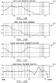
- Figure 10c shows the resulting closed-loop noise canceling and distortion reduction performance 1014.
- Figure 10d shows the resulting audio signal transfer function 1016, illustrating a flat frequency response between 20 Hz and 1 KHz.
- an EQ filter may flatten the response at high frequencies.
Landscapes
- Engineering & Computer Science (AREA)
- Physics & Mathematics (AREA)
- Acoustics & Sound (AREA)
- Multimedia (AREA)
- Signal Processing (AREA)
- Health & Medical Sciences (AREA)
- Audiology, Speech & Language Pathology (AREA)
- General Health & Medical Sciences (AREA)
- Otolaryngology (AREA)
- Soundproofing, Sound Blocking, And Sound Damping (AREA)
Abstract
Description
- One or more embodiments of the present disclosure generally relate to noise-canceling headphones and to concha-style headphones.
- The continuing miniaturization of electronic devices has led to a variety of portable audio devices that deliver audio to a listener via headphones. The miniaturization of electronics has also led to smaller and smaller headphones that produce high quality sound. Some headphones now include noise cancellation systems that include microphones for obtaining external sound data and a controller for reducing or cancelling the external sounds that are generated in the user's environment.
- Ear canal shapes, angles and sizes vary greatly among different persons. Many users feel uncomfortable to wear conventional in-ear headphones despite of different ear tips that come with the headphone products. Air seal, which is essential for good low frequency extension, is poor in many cases. Also, in-ear headphones tend to loosen or even fall off. Around-the-ear headphones are usually heavy, bulky and unsuitable for portable applications. On-ear headphones suffer from poor air seal, which limits their low-frequency performance and overall audio quality.
- One or more embodiments of the present disclosure are directed to a headphone assembly comprising a headband and at least one headphone attached to an end of the headband. The headband may include an earpiece shaped and positioned for placement into a concha of a user's ear. The headband may further include memory foam attached to the earpiece and a porous, outer foam disposed on the earpiece over top the memory foam. The headband may provide a clamping force that creates an air seal between the headphone and corresponding concha without the headphone intruding into the user's ear canal.
- According to one or more embodiments, the outer foam may be acoustically transparent. The earpiece may include a transducer and at least one microphone in proximity to the transducer to receive sound radiated by the transducer and noise. The headphone assembly may further include an active noise canceling (ANC) control system configured to receive an audio input signal from an audio source and provide a filtered audio output signal to the transducer based in part on a perceived frequency response of the headphone as measured by the microphone.
- The earpiece may include an inner first portion and an outer second portion disposed between the inner first portion and the end of the headphone. The inner first portion may define a first chamber of the earpiece and the outer second portion may define a second chamber of the earpiece. The memory foam may be a self-adhesive strip of memory foam wrapped around the first portion of the earpiece. Moreover, the inner first portion of the earpiece may be shaped to fit different concha sizes and shapes to provide a universal fit. The inner first portion of the earpiece may also include a perforated nozzle to provide a sound output port.
- One or more additional embodiments of the present disclosure are directed to a sound system comprising a headphone assembly and an active noise canceling (ANC) control system. The headphone assembly may include a headband and at least one headphone attached to an end of the headband. The headphone may include an earpiece shaped and positioned for placement into a concha of a user's ear. The earpiece may have an inner first portion and an outer second portion disposed between the first portion and the end of the headphone. The inner first portion may define a first chamber of the earpiece and the outer second portion may define a second chamber of the earpiece.
- The headphone may further include a transducer disposed in the second chamber and supported by the outer second portion of the earpiece. A microphone may be disposed in the first chamber and coupled to the inner first portion of the earpiece. The microphone may be positioned in the first chamber to receive sound radiated by the transducer and noise. Memory foam may be adhesively attached to the inner first portion of the earpiece and a porous, outer foam may be disposed on the inner first portion of the earpiece over top the memory foam. The ANC control system may be configured to receive an audio input signal from an audio source and to provide a filtered audio output signal to the transducer based in part on a perceived frequency response of the headphone as measured by the microphone. Moreover, the headband may provide a clamping force that creates an air seal between the headphone and corresponding concha.
- According to one or more embodiments, a volume around the microphone may be occupied with acoustic foam to dampen internal reflections. The second chamber may include damping material to dampen a rear acoustic output of the transducer. The transducer may include a cone formed from a rigid paper membrane to achieve pistonic motion within an audio band. The outer second portion of the earpiece may include a plurality of vent holes for bass tuning. The plurality of vent holes may be lined with acoustic resistance paper.
- Additionally, the ANC control system may include a side-chain filter configured to pass the high-frequency portion of the audio input signal. The ANC control system may further include a loop filter configured to generate the filtered audio output signal based on the high-pass filtered audio input signal and a feedback signal indicative of sound received by the microphone, and to provide the filtered audio output signal to the transducer. The side-chain filter may be a high-pass filter.
- One or more additional embodiments of the present disclosure are directed to a sound system comprising a headphone assembly including at least one concha headphone having an earpiece shaped for placement within a concha of a user's ear. The headphone assembly may further include a headband that provides a clamping force to seal the user's concha with the headphone. The earpiece may include a transducer and at least one microphone.
- The sound system may further comprise a side-chain filter configured to high-pass filter an audio input signal and a loop filter configured to generate a filtered audio output signal based on the high-pass filtered audio input signal and a feedback signal indicative of sound received by the at least one microphone. The loop filter may provide the filtered audio output signal to the transducer.
- According to one or more embodiments, the side-chain filter is a high-pass filter. Further, the at least one microphone may be positioned inside the earpiece to receive sound radiated by the transducer and noise. The earpiece may be shaped to fit different concha sizes and shapes to provide a universal fit.
-
-
Figure 1 is a simplified, exemplary schematic diagram illustrating a sound system including a noise cancelling control system connected to headphones and generating sound waves to a user, according to one or more embodiments of the present disclosure; -
Figure 2 is an illustration of an exemplary headphone assembly, according to one or more embodiments of the present disclosure; -
Figure 3 is a perspective view of an exemplary headphone, according to one or more embodiments of the present disclosure; -
Figure 4 is a simplified, exemplary exploded view of a headphone, according to one or more embodiments of the present disclosure; -
Figure 5 is a side, cross-sectional view of an earpiece, according to one or more embodiments of the present disclosure; -
Figure 6 is a graph illustrating a frequency response of an exemplary headphone worn by multiple users as measured by a built-in microphone, according to one or more embodiments of the present disclosure; -
Figure 7 is a schematic block diagram of a control loop within an active noise-canceling control system, according to one or more embodiments of the present disclosure; -
Figure 8 is a graph illustrating an open loop frequency response of a loop filter, according to one or more embodiments of the present disclosure; -
Figure 9 is a graph illustrating a frequency response of a side-chain filter, according to one or more embodiments of the present disclosure; -
Figure 10a is a graph illustrating a resulting open loop transfer function, according to one or more embodiments of the present disclosure; -
Figure 10b is a graph illustrating a resulting open loop phase response, according to one or more embodiments of the present disclosure; -
Figure 10c is a graph illustrating a resulting closed-loop noise canceling and distortion reduction performance, according to one or more embodiments of the present disclosure; and -
Figure 10d is a graph illustrating a resulting audio signal transfer function, according to one or more embodiments of the present disclosure. - As required, detailed embodiments of the present invention are disclosed herein; however, it is to be understood that the disclosed embodiments are merely exemplary of the invention that may be embodied in various and alternative forms. The figures are not necessarily to scale; some features may be exaggerated or minimized to show details of particular components. Therefore, specific structural and functional details disclosed herein are not to be interpreted as limiting, but merely as a representative basis for teaching one skilled in the art to variously employ the present invention.
- With reference to
Figure 1 , asound system 100 is illustrated in accordance with one or more embodiments of the present disclosure. Thesound system 100 may include an active noise cancelling (ANC)control system 110 and aheadphone assembly 112. TheANC control system 110 may receive an audio input signal from anaudio source 114 and may provide an audio output signal to theheadphone assembly 112. Theheadphone assembly 112 may include aheadband 116 and a pair ofheadphones 118. Eachheadphone 118 may include atransducer 120, or driver, that is positioned in proximity to a user'sear 122. Thetransducer 120 receives the audio output signal and generates audible sound. Eachheadphone 118 may also include one ormore microphones 124 that are positioned between thetransducer 120 and theear 122. Although shown inFigure 1 as having a pair ofheadphones 118, theheadphone assembly 112 may include aheadband 116 and asingle headphone 118. -
Figure 1 depicts a schematic representation ofsound system 100. The illustrated elements are also depicted schematically. For instance, theheadphones 118 are depicted such thattransducer 120 andmicrophone 124 can be illustrated schematically. Thus, the size and shape of theheadphones 118 is not intended to limit the present disclosure to a particular headphone type. Rather, one or more embodiments of the present disclosure may be employed using other types of headphones, such as concha (also referred to as intra-concha) headphones, as will be described in greater detail. -
Figure 2 illustrates theheadphone assembly 112 in greater detail. According to one or more embodiments, eachheadphone 118 may be a concha headphone. A concha headphone is a physical headphone type that rests in the inner bowl (concha) of the ear just outside the ear canal entrance. A concha headphone may also be referred to as an earphone because it is small enough to stick in a user's ear. Unlike insert earphones (or in-ear monitors), however, concha headphones or earphones are not inserted into the ear canal. Eachheadphone 118 may include anear piece 226 and a soft, porousouter foam 228 that is acoustically transparent to provide comfort. Underneath theouter foam 228,memory foam 330 may be wrapped around theear piece 226 as shown inFigure 3 . Thememory foam 330 may be a self-adhesive strip or pre-cut piece. - The
headphone 118 seals in the concha without intruding into a user's ear canal. Air seal is essential for good low frequency extension and overall audio quality, but is difficult to achieve in traditional concha-style headphones. A seal may be achieved with an optimally shapedear piece 226 and the use of the combination of thememory foam 330 and the porous, acoustically transparentouter foam 228. According to one or more embodiments of the present disclosure, theear piece 226 with dual foam may be a replaceable and come in different sizes. A light headband, such asheadband 116, may be used to provide the necessary clamping force for an adequate seal. Accordingly, theheadphones 118 can deliver excellent sound quality, bass extension and comfort. - Referring back to
Figure 2 , theheadband 116 may contain electronic devices (not shown), such as a digital signal processor with headphone amplifier, a Bluetooth receiver, a gyroscope used for head tracking, a rechargeable battery, and user controls (buttons). Theheadband 116 may also contain theANC control system 110. -
Figure 3 shows aheadphone 118 with theouter foam 228 removed to better illustrate thememory foam 330. Theear piece 226 may comprise multiple portions, as will be described in greater detail with respect toFigure 5 . For instance, theear piece 226 may include an inner,first portion 332 and an outer,second portion 334. As shown, thememory foam 330 may be wrapped around thefirst portion 332. When in use, thefirst portion 332 of theear piece 226 may generally reside in the concha of a user's ear. -
Figure 4 is an exploded view of aheadphone 118. As shown, theheadphone 118 includes anearpiece 226, a piece ofmemory foam 330, and a piece ofouter foam 228 for covering the memory foam and at least a portion of the earpiece (e.g., the first portion 332). Thefirst portion 332 of theearpiece 226 may be shaped to fit different concha sizes and shapes, thereby providing a universal fit. The headband 116 (Figure 2 ) in combination with thecontoured earpiece 226 andmemory foam 330 can provide a satisfactory air seal that is not traditionally achieved in a conch-style headphone. Thefirst portion 332 may include anozzle 336 that operates as a sound output port. Accordingly, thenozzle 336 may include aperforated output 338 allowing sound waves to easily pass. Thesecond portion 334 may include multiple vent holes 340 with attached acoustic resistance. For example,acoustic resistance paper 342 may be inserted or otherwise applied to the inside of thesecond portion 334 to cover the vent holes 340. -
Figure 5 is a cross-sectional view of theearpiece 226 according to one or more embodiments of the present disclosure. Thefirst portion 332 may also include afirst chamber 544 providing a frontacoustic volume 546. Thesecond portion 334 of theearpiece 226 may include asecond chamber 548 providing a rearacoustic volume 550. Thesecond portion 334 may house a driver ortransducer 520. The driver ortransducer 520 is adapted to provide accurate pistonic motion throughout the audible band. Thetransducer 520 may include a small surround and amembrane cone 556 with center dome, formed of rigid materials such as fiber-reinforced paper, carbon, bio-cellulose, or anodized aluminum or titanium, or beryllium. This leads to a smooth frequency response, which is essential for good sound quality and functioning noise canceling and error feedback. - The
second portion 334 may provide the necessary acoustic volume and bass tuning through the multiple vent holes 340 with the attachedacoustic resistance paper 342. Thesecond portion 334 may further include dampingmaterial 552 inserted into the cavity of thesecond chamber 548 to dampen the rear acoustic output of thetransducer 520. As examples, the dampingmaterial 552 may be a piece of DACRON® (i.e., polyethylene terephthalate), acoustic foam, or fiberglass. - The
first portion 332 of theearpiece 226 may further include at least one micro-electro-mechanical systems (MEMS)microphone 524. Themicrophone 524 may be located near thenozzle 336 and may face in the general direction of thetransducer 520. Themicrophone 524 may be employed for acoustic noise canceling, error correction, as well as probing the perceived acoustic frequency response, which may be equalized by an inverse filter. The area around themicrophone 524 may be covered withacoustic foam 554 to dampen internal reflections. As mentioned previously, themicrophone 524 is not just used for noise-canceling, but may also provide auto-calibration by measuring and equalizing the perceived frequency response, which can vary greatly due to the shape of individual concha and ear canals. - The
second portion 334 may also include afixture 558 at anend 560 of theearpiece 226 opposite thenozzle 336. Thefixture 558 may connect theearpiece 226 to theheadband 116 and include acable canal 562 for allowing a cable (not shown) to connect to at least thetransducer 520. According to one or more embodiments, the cable may also connect to themicrophone 524, particularly if theANC control system 110 is located outside of the earpiece such as in theheadband 116. According to one or more other embodiments, theANC control system 110 may be disposed within theearpiece 226. -
Figure 6 is a graph illustrating anexemplary frequency response 610 of theheadphones 118 measured with the built-inmicrophone 524 when worn by four different persons. The nearly flat response down to low frequencies (e.g., 50Hz) is indicative of a sufficient air seal in the concha. The remaining deviations may be eliminated by an acoustic error feedback scheme, such as depicted inFigure 7 . - Referring now to
Figure 7 , a noise canceling and errorreduction control loop 710 is illustrated in accordance with one or more embodiments of the present disclosure. Thecontrol loop 710 may be included in theANC control system 110. Thecontrol loop 710 may include anaudio input 712 from an audio source, such asaudio source 114. Thecontrol loop 710 may also include amicrophone input 714 and a filteredaudio output signal 716. Themicrophone input 714 may be a feedback signal indicative of sound received by the at least onemicrophone 524. The filteredaudio output signal 716 may be provided to transducer 520 (not shown). - The control loop may also include a loop filter 718 (H_loop), which may be implemented as a digital filter. The
loop filter 718 may utilize a low latency analog-to-digital converter (ADC) 720 and a low latency digital-to-analog converter (DAC) 722. Theloop filter 718 may also utilize a sufficiently high sampling rate, such as 384 KHz. Other practical sample rates may be in the range from 192 KHz to 3.072 MHz, which is between 4 and 64 times the nominal sample rate of 48 KHz. Additional alternative sampling rates may range from 176.4 KHz to 2.822 MHz if the base rate is 44.1 KHz. Themicrophone input 714 may be converted from analog to digital by theADC 720, and then summed with theaudio input 712 at afirst summation node 724. The result of thefirst summation node 724 is fed to theloop filter 718. - The
ANC control system 110 may generate the filteredaudio output signal 716 atsecond summation node 726. A high-pass filteredaudio input signal 728 is provided to thesecond summation node 726 along a side-chain, orfeedforward path 730. Thesecond summation node 726 may combine the high-pass filtered audio input signal with aloop filter output 732, with the result being fed to theDAC 722 and output as the filteredaudio output signal 716 to thetransducer 520. According to one or more embodiments, thefeedforward path 730 may include a side chain filter 734 (H-side) for generating the high-pass filtered audio input signal. Accordingly, theside chain filter 734 may be a high-pass filter that functions to add the high frequency portion of the audio input signal back at the output. - More details about noise canceling and error reducing filter design, in particular the loop filter and side chain filter described in
Figure 7 , are disclosed inInternational Application Number PCT/US2014/053509, filed August 29, 2014 , which is hereby incorporated by reference. High frequency resonances above 1 KHz, like the one around 4 KHz inFigure 6 of the present disclosure, may be equalized by an equalization (EQ) filter (not shown). The EQ filter may be designed with an auto-calibration method, as is also disclosed International Application NumberPCT/US2014/053509 . -
Figure 8 and Figure 9 show exemplary loop filters 818 and side chain filters 926, respectively, as may be employed in thecontrol loop 710. As shown inFigure 9 , theside chain filter 734 may be a high-pass filter.Figures 10a-d shows the resulting performance of theANC control system 110 using Bode plots. In particular,Figure 10a shows the resulting openloop transfer function 1010.Figure 10b shows the resulting openloop phase response 1012.Figure 10c shows the resulting closed-loop noise canceling anddistortion reduction performance 1014.Figure 10d shows the resulting audiosignal transfer function 1016, illustrating a flat frequency response between 20 Hz and 1 KHz. As mentioned above, an EQ filter may flatten the response at high frequencies. - While exemplary embodiments are described above, it is not intended that these embodiments describe all possible forms of the invention. Rather, the words used in the specification are words of description rather than limitation, and it is understood that various changes may be made without departing from the spirit and scope of the invention. Additionally, the features of various implementing embodiments may be combined to form further embodiments of the invention.
Claims (13)
- A headphone assembly comprising:a headband; andat least one headphone attached to an end of the headband and including:an earpiece shaped and positioned for placement into a concha of a user's ear;memory foam attached to the earpiece; anda porous, outer foam disposed on the earpiece over top the memory foam;wherein the headband provides a clamping force that creates an air seal between the headphone and corresponding concha without the headphone intruding into a user's ear canal.
- The headphone assembly of claim 1, wherein the outer foam is acoustically transparent.
- The headphone assembly of claim 1, wherein the earpiece includes a transducer and at least one microphone in proximity to the transducer to receive sound radiated by the transducer and noise.
- The headphone assembly of claim 3, further comprising:an active noise canceling (ANC) control system configured to receive an audio input signal from an audio source and provide a filtered audio output signal to the transducer based in part on a perceived frequency response of the headphone as measured by the microphone.
- The headphone assembly of any of claims 1-4, wherein the earpiece includes an inner first portion and an outer second portion disposed between the inner first portion and the end of the headphone, the inner first portion defining a first chamber of the earpiece and the outer second portion defining a second chamber of the earpiece.
- The headphone assembly of claim 5, wherein the memory foam is a self-adhesive strip of memory foam wrapped around the first portion of the earpiece; or wherein the inner first portion of the earpiece is shaped to fit different concha sizes and shapes to provide a universal fit or includes a perforated nozzle to provide a sound output port.
- The headphone assembly of claim 1, further comprising:a transducer disposed in the second chamber and supported by the outer second portion of the earpiece,a microphone disposed in the first chamber and coupled to the inner first portion of the earpiece, the microphone positioned in the first chamber to receive sound radiated by the transducer and noise,memory foam adhesively attached to the inner first portion of the earpiece, anda porous, outer foam disposed on the inner first portion of the earpiece over top the memory foam; andan active noise canceling (ANC) control system configured to receive an audio input signal from an audio source and to provide a filtered audio output signal to the transducer based in part on a perceived frequency response of the headphone as measured by the microphone.
- The headphone assembly of claim 7, wherein a volume around the microphone is occupied with acoustic foam to dampen internal reflections.
- The headphone assembly of claim 7, wherein the second chamber includes damping material to dampen a rear acoustic output of the transducer.
- The headphone assembly of any of claims 7-9, wherein the transducer includes a cone formed from a rigid paper membrane to achieve pistonic motion within an audio band.
- The headphone assembly of any of claim 7-10, wherein the ANC control system includes a side-chain filter configured to pass a high-frequency portion of the audio input signal and a loop filter configured to generate the filtered audio output signal based on a high-pass filtered audio input signal and a feedback signal indicative of sound received by the microphone, and to provide the filtered audio output signal to the transducer or wherein the side-chain filter is a high-pass filter.
- The headphone assembly of any preceding claim, wherein the outer second portion includes a plurality of vent holes for bass tuning and, optionally, wherein the plurality of vent holes are lined with acoustic resistance paper.
- The headphone assembly of any preceding claim, wherein the earpiece is shaped to fit different concha sizes and shapes to provide a universal fit.
Applications Claiming Priority (1)
| Application Number | Priority Date | Filing Date | Title |
|---|---|---|---|
| US14/982,421 US9654856B1 (en) | 2015-12-29 | 2015-12-29 | Noise-canceling concha headphone |
Publications (2)
| Publication Number | Publication Date |
|---|---|
| EP3188500A1 true EP3188500A1 (en) | 2017-07-05 |
| EP3188500B1 EP3188500B1 (en) | 2018-08-15 |
Family
ID=57569901
Family Applications (1)
| Application Number | Title | Priority Date | Filing Date |
|---|---|---|---|
| EP16203581.0A Active EP3188500B1 (en) | 2015-12-29 | 2016-12-13 | Noise-canceling concha headphone |
Country Status (3)
| Country | Link |
|---|---|
| US (1) | US9654856B1 (en) |
| EP (1) | EP3188500B1 (en) |
| CN (1) | CN106937195B (en) |
Cited By (1)
| Publication number | Priority date | Publication date | Assignee | Title |
|---|---|---|---|---|
| GB2569691A (en) * | 2017-10-28 | 2019-06-26 | Rice Richard | Ear monitor with speaker in a case |
Families Citing this family (12)
| Publication number | Priority date | Publication date | Assignee | Title |
|---|---|---|---|---|
| DE102017114008A1 (en) * | 2017-06-23 | 2018-12-27 | USound GmbH | In-ear listener |
| CN108200492A (en) * | 2017-07-12 | 2018-06-22 | 北京金锐德路科技有限公司 | Voice control optimization method, device and the earphone and wearable device that integrate In-Ear microphone |
| CN107889006B (en) * | 2017-10-11 | 2019-08-27 | 恒玄科技(上海)有限公司 | A kind of active noise reduction system of flexible modulation de-noising signal delay |
| US11297411B2 (en) | 2018-03-30 | 2022-04-05 | Hewlett-Packard Development Company, L.P. | Microphone units with multiple openings |
| JP7137694B2 (en) | 2018-09-12 | 2022-09-14 | シェンチェン ショックス カンパニー リミテッド | Signal processor with multiple acousto-electric transducers |
| CN109246513A (en) * | 2018-09-30 | 2019-01-18 | 歌尔科技有限公司 | A kind of active noise reduction earphone and its noise-reduction method, device |
| US11064284B2 (en) | 2018-12-28 | 2021-07-13 | X Development Llc | Transparent sound device |
| US11758702B2 (en) * | 2019-04-30 | 2023-09-12 | Apple Inc. | Noise mitigation for head-mounted device |
| CN112822600B (en) * | 2021-01-27 | 2022-11-25 | 歌尔科技有限公司 | Earphone step counting method, earphone and storage medium |
| US12003914B2 (en) * | 2021-06-18 | 2024-06-04 | Anna Barnacka | Vibroacoustic earbud |
| US20230055494A1 (en) * | 2021-08-19 | 2023-02-23 | Dan Clark Audio Inc. | Inline acoustic metamaterial tuning system |
| CN115103284A (en) * | 2022-06-17 | 2022-09-23 | 上海联影微电子科技有限公司 | Acoustic element, acoustic device, and method for manufacturing acoustic element |
Citations (2)
| Publication number | Priority date | Publication date | Assignee | Title |
|---|---|---|---|---|
| WO1999051058A1 (en) * | 1998-03-30 | 1999-10-07 | Hearing Components, Inc. | Disposable sleeve assembly for sound control device and container therefor |
| US6683965B1 (en) * | 1995-10-20 | 2004-01-27 | Bose Corporation | In-the-ear noise reduction headphones |
Family Cites Families (8)
| Publication number | Priority date | Publication date | Assignee | Title |
|---|---|---|---|---|
| GB2434708B (en) * | 2006-01-26 | 2008-02-27 | Sonaptic Ltd | Ambient noise reduction arrangements |
| US7916888B2 (en) | 2006-06-30 | 2011-03-29 | Bose Corporation | In-ear headphones |
| US8666085B2 (en) | 2007-10-02 | 2014-03-04 | Phitek Systems Limited | Component for noise reducing earphone |
| US8831239B2 (en) * | 2012-04-02 | 2014-09-09 | Bose Corporation | Instability detection and avoidance in a feedback system |
| USD697049S1 (en) | 2013-01-24 | 2014-01-07 | Bose Corporation | Set of headphones and battery pack |
| CN203225872U (en) * | 2013-03-15 | 2013-10-02 | 西门子(深圳)磁共振有限公司 | An earphone |
| US9881601B2 (en) * | 2013-06-11 | 2018-01-30 | Bose Corporation | Controlling stability in ANR devices |
| CN204634010U (en) * | 2015-06-09 | 2015-09-09 | 深圳市利霖欣科技有限公司 | A kind of multifunctional earphone |
-
2015
- 2015-12-29 US US14/982,421 patent/US9654856B1/en active Active
-
2016
- 2016-12-13 EP EP16203581.0A patent/EP3188500B1/en active Active
- 2016-12-29 CN CN201611245254.5A patent/CN106937195B/en active Active
Patent Citations (2)
| Publication number | Priority date | Publication date | Assignee | Title |
|---|---|---|---|---|
| US6683965B1 (en) * | 1995-10-20 | 2004-01-27 | Bose Corporation | In-the-ear noise reduction headphones |
| WO1999051058A1 (en) * | 1998-03-30 | 1999-10-07 | Hearing Components, Inc. | Disposable sleeve assembly for sound control device and container therefor |
Cited By (1)
| Publication number | Priority date | Publication date | Assignee | Title |
|---|---|---|---|---|
| GB2569691A (en) * | 2017-10-28 | 2019-06-26 | Rice Richard | Ear monitor with speaker in a case |
Also Published As
| Publication number | Publication date |
|---|---|
| US9654856B1 (en) | 2017-05-16 |
| CN106937195B (en) | 2021-02-19 |
| CN106937195A (en) | 2017-07-07 |
| EP3188500B1 (en) | 2018-08-15 |
Similar Documents
| Publication | Publication Date | Title |
|---|---|---|
| EP3188500B1 (en) | Noise-canceling concha headphone | |
| US10021478B2 (en) | In-the-ear automatic-noise-reduction devices, assemblies, components, and methods | |
| JP6965216B2 (en) | Providing the naturalness of the surroundings with ANR headphones | |
| CN110089129B (en) | On-head/off-head detection of personal sound devices using handset microphones | |
| JP6675414B2 (en) | Speech sensing using multiple microphones | |
| US9813794B2 (en) | Noise reduction with in-ear headphone | |
| CN104429097B (en) | In-Ear Active Noise-Canceling Headphones | |
| JP5265373B2 (en) | Noise elimination earphone | |
| WO2019205049A1 (en) | Vibration removal apparatus and method for dual-microphone earphones | |
| US20140270316A1 (en) | Sound Induction Ear Speaker for Eye Glasses | |
| CN109565626B (en) | Acoustic open-back headphones with active noise cancellation | |
| US20100310093A1 (en) | Headphone apparatus | |
| EP4197198B1 (en) | Earpiece porting | |
| EP3544313B1 (en) | Sound output device and control method for sound output device | |
| US11335315B2 (en) | Wearable electronic device with low frequency noise reduction | |
| JP2023553176A (en) | Earpiece with moving coil transducer and acoustic back space | |
| CN115004717B (en) | Wireless Headset with Improved Wind Noise Immunity | |
| WO2007054807A2 (en) | Noise cancellation earphone | |
| JP6953984B2 (en) | Earphones and signal processing methods for earphones | |
| US20140086429A1 (en) | Single chamber headphone apparatus | |
| US12047725B2 (en) | Adaptive eartip for true wireless stereo headsets | |
| JP7052300B2 (en) | Acoustic output device | |
| WO2022116765A1 (en) | Earphone and mobile terminal | |
| CN112236814A (en) | Real-time detection of feedforward instability | |
| JP2019087868A (en) | Sound output device |
Legal Events
| Date | Code | Title | Description |
|---|---|---|---|
| PUAI | Public reference made under article 153(3) epc to a published international application that has entered the european phase |
Free format text: ORIGINAL CODE: 0009012 |
|
| AK | Designated contracting states |
Kind code of ref document: A1 Designated state(s): AL AT BE BG CH CY CZ DE DK EE ES FI FR GB GR HR HU IE IS IT LI LT LU LV MC MK MT NL NO PL PT RO RS SE SI SK SM TR |
|
| AX | Request for extension of the european patent |
Extension state: BA ME |
|
| 17P | Request for examination filed |
Effective date: 20171110 |
|
| RBV | Designated contracting states (corrected) |
Designated state(s): AL AT BE BG CH CY CZ DE DK EE ES FI FR GB GR HR HU IE IS IT LI LT LU LV MC MK MT NL NO PL PT RO RS SE SI SK SM TR |
|
| RIC1 | Information provided on ipc code assigned before grant |
Ipc: H04R 1/10 20060101AFI20180228BHEP |
|
| GRAP | Despatch of communication of intention to grant a patent |
Free format text: ORIGINAL CODE: EPIDOSNIGR1 |
|
| INTG | Intention to grant announced |
Effective date: 20180410 |
|
| GRAS | Grant fee paid |
Free format text: ORIGINAL CODE: EPIDOSNIGR3 |
|
| GRAA | (expected) grant |
Free format text: ORIGINAL CODE: 0009210 |
|
| AK | Designated contracting states |
Kind code of ref document: B1 Designated state(s): AL AT BE BG CH CY CZ DE DK EE ES FI FR GB GR HR HU IE IS IT LI LT LU LV MC MK MT NL NO PL PT RO RS SE SI SK SM TR |
|
| REG | Reference to a national code |
Ref country code: CH Ref legal event code: EP Ref country code: GB Ref legal event code: FG4D Ref country code: AT Ref legal event code: REF Ref document number: 1031178 Country of ref document: AT Kind code of ref document: T Effective date: 20180815 |
|
| REG | Reference to a national code |
Ref country code: IE Ref legal event code: FG4D |
|
| REG | Reference to a national code |
Ref country code: DE Ref legal event code: R096 Ref document number: 602016004799 Country of ref document: DE |
|
| REG | Reference to a national code |
Ref country code: NL Ref legal event code: MP Effective date: 20180815 |
|
| REG | Reference to a national code |
Ref country code: LT Ref legal event code: MG4D |
|
| REG | Reference to a national code |
Ref country code: AT Ref legal event code: MK05 Ref document number: 1031178 Country of ref document: AT Kind code of ref document: T Effective date: 20180815 |
|
| PG25 | Lapsed in a contracting state [announced via postgrant information from national office to epo] |
Ref country code: SE Free format text: LAPSE BECAUSE OF FAILURE TO SUBMIT A TRANSLATION OF THE DESCRIPTION OR TO PAY THE FEE WITHIN THE PRESCRIBED TIME-LIMIT Effective date: 20180815 Ref country code: LT Free format text: LAPSE BECAUSE OF FAILURE TO SUBMIT A TRANSLATION OF THE DESCRIPTION OR TO PAY THE FEE WITHIN THE PRESCRIBED TIME-LIMIT Effective date: 20180815 Ref country code: IS Free format text: LAPSE BECAUSE OF FAILURE TO SUBMIT A TRANSLATION OF THE DESCRIPTION OR TO PAY THE FEE WITHIN THE PRESCRIBED TIME-LIMIT Effective date: 20181215 Ref country code: RS Free format text: LAPSE BECAUSE OF FAILURE TO SUBMIT A TRANSLATION OF THE DESCRIPTION OR TO PAY THE FEE WITHIN THE PRESCRIBED TIME-LIMIT Effective date: 20180815 Ref country code: NL Free format text: LAPSE BECAUSE OF FAILURE TO SUBMIT A TRANSLATION OF THE DESCRIPTION OR TO PAY THE FEE WITHIN THE PRESCRIBED TIME-LIMIT Effective date: 20180815 Ref country code: BG Free format text: LAPSE BECAUSE OF FAILURE TO SUBMIT A TRANSLATION OF THE DESCRIPTION OR TO PAY THE FEE WITHIN THE PRESCRIBED TIME-LIMIT Effective date: 20181115 Ref country code: FI Free format text: LAPSE BECAUSE OF FAILURE TO SUBMIT A TRANSLATION OF THE DESCRIPTION OR TO PAY THE FEE WITHIN THE PRESCRIBED TIME-LIMIT Effective date: 20180815 Ref country code: NO Free format text: LAPSE BECAUSE OF FAILURE TO SUBMIT A TRANSLATION OF THE DESCRIPTION OR TO PAY THE FEE WITHIN THE PRESCRIBED TIME-LIMIT Effective date: 20181115 Ref country code: GR Free format text: LAPSE BECAUSE OF FAILURE TO SUBMIT A TRANSLATION OF THE DESCRIPTION OR TO PAY THE FEE WITHIN THE PRESCRIBED TIME-LIMIT Effective date: 20181116 Ref country code: AT Free format text: LAPSE BECAUSE OF FAILURE TO SUBMIT A TRANSLATION OF THE DESCRIPTION OR TO PAY THE FEE WITHIN THE PRESCRIBED TIME-LIMIT Effective date: 20180815 |
|
| PG25 | Lapsed in a contracting state [announced via postgrant information from national office to epo] |
Ref country code: HR Free format text: LAPSE BECAUSE OF FAILURE TO SUBMIT A TRANSLATION OF THE DESCRIPTION OR TO PAY THE FEE WITHIN THE PRESCRIBED TIME-LIMIT Effective date: 20180815 Ref country code: LV Free format text: LAPSE BECAUSE OF FAILURE TO SUBMIT A TRANSLATION OF THE DESCRIPTION OR TO PAY THE FEE WITHIN THE PRESCRIBED TIME-LIMIT Effective date: 20180815 Ref country code: AL Free format text: LAPSE BECAUSE OF FAILURE TO SUBMIT A TRANSLATION OF THE DESCRIPTION OR TO PAY THE FEE WITHIN THE PRESCRIBED TIME-LIMIT Effective date: 20180815 |
|
| PG25 | Lapsed in a contracting state [announced via postgrant information from national office to epo] |
Ref country code: PL Free format text: LAPSE BECAUSE OF FAILURE TO SUBMIT A TRANSLATION OF THE DESCRIPTION OR TO PAY THE FEE WITHIN THE PRESCRIBED TIME-LIMIT Effective date: 20180815 Ref country code: ES Free format text: LAPSE BECAUSE OF FAILURE TO SUBMIT A TRANSLATION OF THE DESCRIPTION OR TO PAY THE FEE WITHIN THE PRESCRIBED TIME-LIMIT Effective date: 20180815 Ref country code: EE Free format text: LAPSE BECAUSE OF FAILURE TO SUBMIT A TRANSLATION OF THE DESCRIPTION OR TO PAY THE FEE WITHIN THE PRESCRIBED TIME-LIMIT Effective date: 20180815 Ref country code: RO Free format text: LAPSE BECAUSE OF FAILURE TO SUBMIT A TRANSLATION OF THE DESCRIPTION OR TO PAY THE FEE WITHIN THE PRESCRIBED TIME-LIMIT Effective date: 20180815 Ref country code: CZ Free format text: LAPSE BECAUSE OF FAILURE TO SUBMIT A TRANSLATION OF THE DESCRIPTION OR TO PAY THE FEE WITHIN THE PRESCRIBED TIME-LIMIT Effective date: 20180815 Ref country code: IT Free format text: LAPSE BECAUSE OF FAILURE TO SUBMIT A TRANSLATION OF THE DESCRIPTION OR TO PAY THE FEE WITHIN THE PRESCRIBED TIME-LIMIT Effective date: 20180815 |
|
| REG | Reference to a national code |
Ref country code: DE Ref legal event code: R097 Ref document number: 602016004799 Country of ref document: DE |
|
| PG25 | Lapsed in a contracting state [announced via postgrant information from national office to epo] |
Ref country code: SM Free format text: LAPSE BECAUSE OF FAILURE TO SUBMIT A TRANSLATION OF THE DESCRIPTION OR TO PAY THE FEE WITHIN THE PRESCRIBED TIME-LIMIT Effective date: 20180815 Ref country code: SK Free format text: LAPSE BECAUSE OF FAILURE TO SUBMIT A TRANSLATION OF THE DESCRIPTION OR TO PAY THE FEE WITHIN THE PRESCRIBED TIME-LIMIT Effective date: 20180815 Ref country code: DK Free format text: LAPSE BECAUSE OF FAILURE TO SUBMIT A TRANSLATION OF THE DESCRIPTION OR TO PAY THE FEE WITHIN THE PRESCRIBED TIME-LIMIT Effective date: 20180815 |
|
| PLBE | No opposition filed within time limit |
Free format text: ORIGINAL CODE: 0009261 |
|
| STAA | Information on the status of an ep patent application or granted ep patent |
Free format text: STATUS: NO OPPOSITION FILED WITHIN TIME LIMIT |
|
| 26N | No opposition filed |
Effective date: 20190516 |
|
| PG25 | Lapsed in a contracting state [announced via postgrant information from national office to epo] |
Ref country code: SI Free format text: LAPSE BECAUSE OF FAILURE TO SUBMIT A TRANSLATION OF THE DESCRIPTION OR TO PAY THE FEE WITHIN THE PRESCRIBED TIME-LIMIT Effective date: 20180815 Ref country code: LU Free format text: LAPSE BECAUSE OF NON-PAYMENT OF DUE FEES Effective date: 20181213 Ref country code: MC Free format text: LAPSE BECAUSE OF FAILURE TO SUBMIT A TRANSLATION OF THE DESCRIPTION OR TO PAY THE FEE WITHIN THE PRESCRIBED TIME-LIMIT Effective date: 20180815 |
|
| REG | Reference to a national code |
Ref country code: IE Ref legal event code: MM4A |
|
| REG | Reference to a national code |
Ref country code: BE Ref legal event code: MM Effective date: 20181231 |
|
| PG25 | Lapsed in a contracting state [announced via postgrant information from national office to epo] |
Ref country code: IE Free format text: LAPSE BECAUSE OF NON-PAYMENT OF DUE FEES Effective date: 20181213 Ref country code: FR Free format text: LAPSE BECAUSE OF NON-PAYMENT OF DUE FEES Effective date: 20181231 |
|
| PG25 | Lapsed in a contracting state [announced via postgrant information from national office to epo] |
Ref country code: BE Free format text: LAPSE BECAUSE OF NON-PAYMENT OF DUE FEES Effective date: 20181231 |
|
| PG25 | Lapsed in a contracting state [announced via postgrant information from national office to epo] |
Ref country code: MT Free format text: LAPSE BECAUSE OF NON-PAYMENT OF DUE FEES Effective date: 20181213 |
|
| PG25 | Lapsed in a contracting state [announced via postgrant information from national office to epo] |
Ref country code: TR Free format text: LAPSE BECAUSE OF FAILURE TO SUBMIT A TRANSLATION OF THE DESCRIPTION OR TO PAY THE FEE WITHIN THE PRESCRIBED TIME-LIMIT Effective date: 20180815 |
|
| PG25 | Lapsed in a contracting state [announced via postgrant information from national office to epo] |
Ref country code: PT Free format text: LAPSE BECAUSE OF FAILURE TO SUBMIT A TRANSLATION OF THE DESCRIPTION OR TO PAY THE FEE WITHIN THE PRESCRIBED TIME-LIMIT Effective date: 20180815 |
|
| PG25 | Lapsed in a contracting state [announced via postgrant information from national office to epo] |
Ref country code: HU Free format text: LAPSE BECAUSE OF FAILURE TO SUBMIT A TRANSLATION OF THE DESCRIPTION OR TO PAY THE FEE WITHIN THE PRESCRIBED TIME-LIMIT; INVALID AB INITIO Effective date: 20161213 Ref country code: CY Free format text: LAPSE BECAUSE OF FAILURE TO SUBMIT A TRANSLATION OF THE DESCRIPTION OR TO PAY THE FEE WITHIN THE PRESCRIBED TIME-LIMIT Effective date: 20180815 Ref country code: MK Free format text: LAPSE BECAUSE OF NON-PAYMENT OF DUE FEES Effective date: 20180815 |
|
| REG | Reference to a national code |
Ref country code: CH Ref legal event code: PL |
|
| PG25 | Lapsed in a contracting state [announced via postgrant information from national office to epo] |
Ref country code: CH Free format text: LAPSE BECAUSE OF NON-PAYMENT OF DUE FEES Effective date: 20191231 Ref country code: LI Free format text: LAPSE BECAUSE OF NON-PAYMENT OF DUE FEES Effective date: 20191231 |
|
| P01 | Opt-out of the competence of the unified patent court (upc) registered |
Effective date: 20230527 |
|
| PGFP | Annual fee paid to national office [announced via postgrant information from national office to epo] |
Ref country code: DE Payment date: 20251126 Year of fee payment: 10 |
|
| PGFP | Annual fee paid to national office [announced via postgrant information from national office to epo] |
Ref country code: GB Payment date: 20251119 Year of fee payment: 10 |