EP3188483A1 - Video receiving method and receiver decoding and recompressing video for storage - Google Patents
Video receiving method and receiver decoding and recompressing video for storage Download PDFInfo
- Publication number
- EP3188483A1 EP3188483A1 EP16202782.5A EP16202782A EP3188483A1 EP 3188483 A1 EP3188483 A1 EP 3188483A1 EP 16202782 A EP16202782 A EP 16202782A EP 3188483 A1 EP3188483 A1 EP 3188483A1
- Authority
- EP
- European Patent Office
- Prior art keywords
- decoder
- reference frame
- data
- frame data
- buffer
- Prior art date
- Legal status (The legal status is an assumption and is not a legal conclusion. Google has not performed a legal analysis and makes no representation as to the accuracy of the status listed.)
- Withdrawn
Links
Images


Classifications
-
- H—ELECTRICITY
- H04—ELECTRIC COMMUNICATION TECHNIQUE
- H04N—PICTORIAL COMMUNICATION, e.g. TELEVISION
- H04N19/00—Methods or arrangements for coding, decoding, compressing or decompressing digital video signals
- H04N19/42—Methods or arrangements for coding, decoding, compressing or decompressing digital video signals characterised by implementation details or hardware specially adapted for video compression or decompression, e.g. dedicated software implementation
-
- H—ELECTRICITY
- H04—ELECTRIC COMMUNICATION TECHNIQUE
- H04N—PICTORIAL COMMUNICATION, e.g. TELEVISION
- H04N21/00—Selective content distribution, e.g. interactive television or video on demand [VOD]
- H04N21/40—Client devices specifically adapted for the reception of or interaction with content, e.g. set-top-box [STB]; Operations thereof
- H04N21/43—Processing of content or additional data, e.g. demultiplexing additional data from a digital video stream; Elementary client operations, e.g. monitoring of home network or synchronising decoder's clock; Client middleware
- H04N21/44—Processing of video elementary streams, e.g. splicing a video clip retrieved from local storage with an incoming video stream or rendering scenes according to encoded video stream scene graphs
- H04N21/4402—Processing of video elementary streams, e.g. splicing a video clip retrieved from local storage with an incoming video stream or rendering scenes according to encoded video stream scene graphs involving reformatting operations of video signals for household redistribution, storage or real-time display
- H04N21/440218—Processing of video elementary streams, e.g. splicing a video clip retrieved from local storage with an incoming video stream or rendering scenes according to encoded video stream scene graphs involving reformatting operations of video signals for household redistribution, storage or real-time display by transcoding between formats or standards, e.g. from MPEG-2 to MPEG-4
-
- H—ELECTRICITY
- H04—ELECTRIC COMMUNICATION TECHNIQUE
- H04N—PICTORIAL COMMUNICATION, e.g. TELEVISION
- H04N19/00—Methods or arrangements for coding, decoding, compressing or decompressing digital video signals
- H04N19/10—Methods or arrangements for coding, decoding, compressing or decompressing digital video signals using adaptive coding
- H04N19/169—Methods or arrangements for coding, decoding, compressing or decompressing digital video signals using adaptive coding characterised by the coding unit, i.e. the structural portion or semantic portion of the video signal being the object or the subject of the adaptive coding
- H04N19/17—Methods or arrangements for coding, decoding, compressing or decompressing digital video signals using adaptive coding characterised by the coding unit, i.e. the structural portion or semantic portion of the video signal being the object or the subject of the adaptive coding the unit being an image region, e.g. an object
- H04N19/174—Methods or arrangements for coding, decoding, compressing or decompressing digital video signals using adaptive coding characterised by the coding unit, i.e. the structural portion or semantic portion of the video signal being the object or the subject of the adaptive coding the unit being an image region, e.g. an object the region being a slice, e.g. a line of blocks or a group of blocks
-
- H—ELECTRICITY
- H04—ELECTRIC COMMUNICATION TECHNIQUE
- H04N—PICTORIAL COMMUNICATION, e.g. TELEVISION
- H04N19/00—Methods or arrangements for coding, decoding, compressing or decompressing digital video signals
- H04N19/42—Methods or arrangements for coding, decoding, compressing or decompressing digital video signals characterised by implementation details or hardware specially adapted for video compression or decompression, e.g. dedicated software implementation
- H04N19/423—Methods or arrangements for coding, decoding, compressing or decompressing digital video signals characterised by implementation details or hardware specially adapted for video compression or decompression, e.g. dedicated software implementation characterised by memory arrangements
- H04N19/426—Methods or arrangements for coding, decoding, compressing or decompressing digital video signals characterised by implementation details or hardware specially adapted for video compression or decompression, e.g. dedicated software implementation characterised by memory arrangements using memory downsizing methods
- H04N19/428—Recompression, e.g. by spatial or temporal decimation
-
- H—ELECTRICITY
- H04—ELECTRIC COMMUNICATION TECHNIQUE
- H04N—PICTORIAL COMMUNICATION, e.g. TELEVISION
- H04N19/00—Methods or arrangements for coding, decoding, compressing or decompressing digital video signals
- H04N19/42—Methods or arrangements for coding, decoding, compressing or decompressing digital video signals characterised by implementation details or hardware specially adapted for video compression or decompression, e.g. dedicated software implementation
- H04N19/43—Hardware specially adapted for motion estimation or compensation
- H04N19/433—Hardware specially adapted for motion estimation or compensation characterised by techniques for memory access
-
- H—ELECTRICITY
- H04—ELECTRIC COMMUNICATION TECHNIQUE
- H04N—PICTORIAL COMMUNICATION, e.g. TELEVISION
- H04N19/00—Methods or arrangements for coding, decoding, compressing or decompressing digital video signals
- H04N19/42—Methods or arrangements for coding, decoding, compressing or decompressing digital video signals characterised by implementation details or hardware specially adapted for video compression or decompression, e.g. dedicated software implementation
- H04N19/436—Methods or arrangements for coding, decoding, compressing or decompressing digital video signals characterised by implementation details or hardware specially adapted for video compression or decompression, e.g. dedicated software implementation using parallelised computational arrangements
-
- H—ELECTRICITY
- H04—ELECTRIC COMMUNICATION TECHNIQUE
- H04N—PICTORIAL COMMUNICATION, e.g. TELEVISION
- H04N19/00—Methods or arrangements for coding, decoding, compressing or decompressing digital video signals
- H04N19/44—Decoders specially adapted therefor, e.g. video decoders which are asymmetric with respect to the encoder
-
- H—ELECTRICITY
- H04—ELECTRIC COMMUNICATION TECHNIQUE
- H04N—PICTORIAL COMMUNICATION, e.g. TELEVISION
- H04N21/00—Selective content distribution, e.g. interactive television or video on demand [VOD]
- H04N21/20—Servers specifically adapted for the distribution of content, e.g. VOD servers; Operations thereof
- H04N21/23—Processing of content or additional data; Elementary server operations; Server middleware
- H04N21/234—Processing of video elementary streams, e.g. splicing of video streams or manipulating encoded video stream scene graphs
-
- H—ELECTRICITY
- H04—ELECTRIC COMMUNICATION TECHNIQUE
- H04N—PICTORIAL COMMUNICATION, e.g. TELEVISION
- H04N21/00—Selective content distribution, e.g. interactive television or video on demand [VOD]
- H04N21/20—Servers specifically adapted for the distribution of content, e.g. VOD servers; Operations thereof
- H04N21/23—Processing of content or additional data; Elementary server operations; Server middleware
- H04N21/234—Processing of video elementary streams, e.g. splicing of video streams or manipulating encoded video stream scene graphs
- H04N21/2343—Processing of video elementary streams, e.g. splicing of video streams or manipulating encoded video stream scene graphs involving reformatting operations of video signals for distribution or compliance with end-user requests or end-user device requirements
- H04N21/234318—Processing of video elementary streams, e.g. splicing of video streams or manipulating encoded video stream scene graphs involving reformatting operations of video signals for distribution or compliance with end-user requests or end-user device requirements by decomposing into objects, e.g. MPEG-4 objects
-
- H—ELECTRICITY
- H04—ELECTRIC COMMUNICATION TECHNIQUE
- H04N—PICTORIAL COMMUNICATION, e.g. TELEVISION
- H04N21/00—Selective content distribution, e.g. interactive television or video on demand [VOD]
- H04N21/40—Client devices specifically adapted for the reception of or interaction with content, e.g. set-top-box [STB]; Operations thereof
- H04N21/43—Processing of content or additional data, e.g. demultiplexing additional data from a digital video stream; Elementary client operations, e.g. monitoring of home network or synchronising decoder's clock; Client middleware
- H04N21/44—Processing of video elementary streams, e.g. splicing a video clip retrieved from local storage with an incoming video stream or rendering scenes according to encoded video stream scene graphs
- H04N21/44004—Processing of video elementary streams, e.g. splicing a video clip retrieved from local storage with an incoming video stream or rendering scenes according to encoded video stream scene graphs involving video buffer management, e.g. video decoder buffer or video display buffer
-
- G—PHYSICS
- G09—EDUCATION; CRYPTOGRAPHY; DISPLAY; ADVERTISING; SEALS
- G09G—ARRANGEMENTS OR CIRCUITS FOR CONTROL OF INDICATING DEVICES USING STATIC MEANS TO PRESENT VARIABLE INFORMATION
- G09G2350/00—Solving problems of bandwidth in display systems
Definitions
- One or more aspects of embodiments of the present invention relate to the transmission of compressed video data, and more particularly to a system and method for encoding uncompressed video data and decoding compressed video data using compressed reference frame data.
- a video display may receive data at relatively high data rates from a video data source, such as a video card in a computer.
- the video data may be compressed at the video data source and decompressed at the display, to enable the sending of higher effective data rates through a channel having a certain capacity.
- the decoding of video data may involve using reference frames, e.g., previously displayed frames of video (or uncompressed and displayed frames of video). Storing the reference frames may require significant amounts of memory, which may be costly.
- a transmitter receives uncompressed video data from a video source, and compresses it using one or more reference frames.
- a receiver receives the compressed video data and decodes it, using the same reference frames, to form display data.
- the reference frames are stored in compressed form in both the transmitter and the receiver. Each frame of display data becomes a reference frame for the decoding of a subsequent frame.
- a video receiver including: a first decoder, configured to: receive compressed video data and uncompressed reference frame data; and generate uncompressed display data; a first encoder, configured to: receive the display data from the first decoder; and compress the display data to form compressed reference frame data; a reference frame data buffer, configured to store the compressed reference frame data; and a second decoder, configured to: retrieve compressed reference frame data from the reference frame data buffer; and decode the compressed reference frame data to form the uncompressed reference frame data, wherein the first encoder and second decoder are configured to operate at a lower compression ratio than the first decoder.
- the first decoder is an advanced display stream compression decoder.
- the first encoder is a display stream compression encoder and the second decoder is a display stream compression decoder.
- the first decoder is configured to operate at a compression ratio of 4:1.
- the first encoder is configured to operate with a compression factor of at least 2:1.
- the first encoder is configured to operate with a compression factor of at least 2.4:1.
- each reference frame consists of n slices, each slice corresponding to a rectangular portion of the reference frame, and the first encoder is configured to compress the display data one slice at a time.
- the reference frame data buffer includes n+1 slice buffers, n being a positive integer, each slice buffer having a size sufficient to store one compressed slice of a reference frame.
- the second decoder is configured to decode data from one slice buffer at a time.
- the second decoder is configured to generate 2 lines of uncompressed reference frame data at a time.
- the second decoder is configured to generate 4 lines of uncompressed reference frame data at a time.
- the second decoder is configured to generate 6 lines of uncompressed reference frame data at a time.
- the receiver is configured: to save compressed reference frame data from the first encoder into a temporary slice buffer of the n+1 slice buffers, while the second decoder decodes data from a first slice buffer of the n+1 slice buffers, and to complete the saving of compressed reference frame data into the temporary slice buffer when the second decoder completes decoding data from the first slice buffer, and to copy the compressed reference frame data from the temporary slice buffer to the first slice buffer when the second decoder completes decoding data from the first slice buffer.
- the slice buffer is a ring buffer; the receiver is configured: to save compressed reference frame data into a first slice buffer, of the n+1 slice buffers, identified by a first pointer, while the second decoder decodes data from a second slice buffer, of the n+1 slice buffers, identified by a second pointer, the first slice buffer and the second slice buffer being circularly adjacent in the ring buffer; to complete the saving of compressed reference frame data into the first slice buffer when the second decoder completes decoding compressed reference frame data from a second slice buffer; and to advance both the first pointer and the second pointer to identify a respective subsequent slice buffer of the n+1 slice buffers, the first pointer being advanced to point to the second slice buffer, both the first pointer and the second pointer being advanced in the same direction.
- a video receiver including a first display data generator and a second display data generator, each of the first display data generator and the second display data generator including: a first decoder, configured to: receive compressed video data and uncompressed reference frame data; and generate uncompressed display data; a first encoder, configured to: receive the display data from the first decoder; and compress the display data to form compressed reference frame data; a reference frame data buffer, configured to store the compressed reference frame data; and a second decoder, configured to: retrieve compressed reference frame data from the reference frame data buffer; and decode the compressed reference frame data to form the uncompressed reference frame data, wherein the first encoder and second decoder are configured to operate at a lower compression ratio than the first decoder.
- a first decoder configured to: receive compressed video data and uncompressed reference frame data; and generate uncompressed display data
- a first encoder configured to: receive the display data from the first decoder; and compress the display data to form compressed reference frame data
- a reference frame data buffer configured to store
- the first decoder is configured to generate a first half of each line of uncompressed video data and the second decoder is configured to generate a second half of each line of uncompressed video data.
- the first decoder is an advanced display stream compression decoder; the first encoder is a display stream compression encoder; and the second decoder is a display stream compression decoder.
- a method for generating display data including: receiving, by a first decoder, compressed video data, and uncompressed reference frame data; generating, by the first decoder, uncompressed display data; receiving, by a first encoder, the display data from the first decoder; compressing, by the first encoder, the display data to form compressed reference frame data; storing, by a reference frame data buffer, the compressed reference frame data; retrieving, by a second decoder, compressed reference frame data from the reference frame data buffer; and decoding, by the second decoder, the compressed reference frame data to form the uncompressed reference frame data, wherein the first encoder and second decoder are configured to operate at a lower compression ratio than the first decoder.
- the first decoder is an advanced display stream compression decoder.
- the first encoder is a display stream compression encoder and the second decoder is a display stream compression decoder.
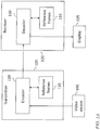
- a video data source 100 may generate successive frames of video data.
- a transmitter 105 at or in the video data source may include a main encoder 110 and a plurality of reference frames 115.
- the main encoder 110 may receive uncompressed video data from the video data source 100, and compress the frames of video data, using the reference frames 115, to form compressed video data.
- the compressed video data may be transmitted to a receiver 120 that is connected to or in a recipient of video data, such as a display 125.
- the receiver may include a main decoder 130 and a plurality of reference frames 115, and the main decoder 130 may decode the received compressed video data, using the reference frames 115, to reconstitute the original frames of video data, or, if the compression and decompression is not lossless, to generate new frames of video data that resemble the original frames of video data.
- the system for encoding and decoding the video data may be referred to as an encoder-decoder or "video codec".
- the reference frames may be previously displayed frames.
- the compressed video data may include information about differences between the original video frames, and the receiver may store one or more previously displayed frames and infer a current frame (i.e., a frame to be displayed) from the one or more previously displayed frames and the information about differences between the original video frames that it receives in the compressed video data.
- a receiver is identified, for clarity, as a separate element from a display, even though in a commercial product the receiver and the display may share elements such as an enclosure, a power supply, or an integrated circuit substrate.
- the combination of the receiver and the display may be referred to as a "display device".
- the portion of the display that forms a viewable image may be referred to as the "display panel".
- the display may include a display panel configured to display images each consisting of a plurality of pixels arranged in rows (or "lines") and columns; each pixel may include (e.g., consist of) three subpixels (e.g., a red subpixel, a green subpixel, and a blue subpixel).
- a "receiver” as used herein is a circuit that receives compressed video data and generates uncompressed video data
- a "display” is an apparatus that receives uncompressed video data and generates images for viewing by a user.
- coding refers to generating compressed data (e.g., video data or reference frame data) from uncompressed data
- decoding refers to generating uncompressed data (e.g., video data or reference frame data) from compressed data.
- reference frame data refers to data that represent one or more reference frames or one or more portions of one or more reference frames.
- the one or more reference frames are stored in compressed form.
- the compression method used to store the one or more reference frames may be the same as, or different from, the compression method used by the transmitter to generate the compressed video data.
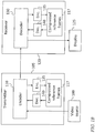
- the reference frames are encoded by a reference frame encoder 135, stored as compressed reference frame data, (e.g., compressed reference frames 117) and decoded when needed by a reference frame decoder 140.
- the encoding and decoding may be performed in the receiver (to reduce the amount of memory used in the receiver to store the reference frame data), and the same encoding and decoding may be performed in the transmitter, so that, if the combined effect of the reference frame encoder 135 and the reference frame decoder 140 is not lossless, the encoder 110 will use the same reconstituted (i.e., encoded and decoded) reference frames as the decoder 130.
- the main decoder 130 may be an advanced display stream compression (ADSC) decoder, e.g., it may be a decoder, operating at a compression ratio of 4:1, complying with an ADSC standard being promulgated by the Video Electronics Standards Association.
- the reference frame encoder 135 may be a display stream compression (DSC) encoder, e.g., it may be a decoder complying with a DSC standard promulgated by the Video Electronics Standards Association, and the reference frame decoder 140 may be a DSC decoder.
- DSC display stream compression
- the reference frame encoder 135 may operate with a compression ratio of 3:1 (or, in some embodiments, of 2:1 or of 1:1); accordingly the reference frame decoder 140 may operate with a compression ratio (or "decompression ratio") of 3:1 (or, in some embodiments, of 2:1 or of 1:1, or with a non-integral compression ratio, e.g., 2.4:1).
- the compression ratio may affect reconstruction quality.
- ADSC and DSC encoders and decoders may operate to within 1/16 bpp (bits per pixel) resolution where "bits per pixel" refers to the number of bits required to store a pixel in compressed form.
- the main decoder 130 and the reference frame decoder 140 are both DSC decoders, and the reference frame encoder 135 is a DSC encoder.
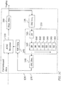
- the main decoder 130 may receive compressed data from the transmitter, and uncompressed reference frame data (which may be stored temporarily in an uncompressed reference frame data buffer 145) from the reference frame decoder 140, and it may generate display data (which may be stored temporarily in a display data buffer 150).
- the display data may be generated, e.g., 2 lines at a time (or 4 lines at a time, or 6 lines at a time), stored temporarily in the display data buffer 150, and sent to the display, and also to the reference frame encoder 135.
- the reference frame encoder 135 may encode the display data, e.g., 2 lines at a time (or 4 lines at a time, or 6 lines at a time), and store it in a reference frame data buffer 155.
- the compressed display data may then be used as reference frame data for decoding the next frame of video data.
- the reference frame decoder 140 may retrieve compressed reference frame data (which may be compressed data from the last displayed image) from the reference frame data buffer 155, decode it to form uncompressed reference frame data, and feed the uncompressed reference frame data to the main decoder 130 (e.g., via the uncompressed reference frame data buffer 145).
- the reference frame decoder 140 may operate on blocks of data referred to as slices, each of which may correspond to a rectangular portion of a frame. For example, for a display that is 1920 pixels wide and 1080 pixels high, a slice may correspond to (i.e., contain data from) a rectangle with width of 1920 pixels and a height of 108 pixels, so that that each frame consists of 10 slices.
- the reference frame data buffer 155 may accordingly be composed of a plurality of slice buffers 160, 165. As illustrated in FIG. 1C , the slice buffers 160 may be arranged in a ring buffer, and the reference frame data buffer 155 may include an additional slice buffer referred to as a temporary slice buffer 165. The number of slice buffers 160 in the ring buffer may be equal to the number of slices in a frame. In operation, while the reference frame decoder 140 decodes compressed reference frame data from one slice buffer, the reference frame encoder 135 may encode the display data from a slice of the current display frame and store the compressed data as compressed reference frame data (e.g., to be used as a reference frame when the next frame of video is to be decoded) in the temporary slice buffer.
- compressed reference frame data e.g., to be used as a reference frame when the next frame of video is to be decoded
- the reference frame decoder 140 has read all of the data from the current slice buffer 160, (ii) the final two lines of display data for the slice have been sent to the display, and (iii) the reference frame encoder 135 has encoded the final lines of display data and saved the corresponding compressed data into the temporary slice buffer 165. Then, (i) the contents of the temporary slice buffer 165 may be copied into slice buffer 160 that the reference frame decoder 140 read during the previous frame, (ii) the reference frame decoder 140 may begin decoding compressed reference frame data from the next slice buffer 160 in the ring buffer, and (iii) the reference frame encoder 135 may begin again encoding display data and saving the compressed data in the temporary slice buffer 165.
- Consecutive slice buffers need not be adjacent in physical memory; two slice buffers may be said to be "circularly adjacent" in the ring buffer when the ring buffer is implemented such that processing progresses from one to the other (e.g., as a result of buffer pointers being advanced in the receiver).
- the reference frame data buffer 155 may contain a ring buffer including n+1 slice buffers (instead of a ring buffer with n slice buffers and a temporary slice buffer 165).
- reference frame decoder 140 may read from one slice buffer 160, and the reference frame encoder 135 may write compressed data to an adjacent slice buffer 160, which may be the slice buffer 160 that the reference frame decoder 140 read from during the previous frame.
- the current read buffer i.e., the slice buffer 160 current being read from
- the current write buffer i.e., the slice buffer 160 current being written to
- each of the read pointer and the write pointer may be advanced to point to the respective next slice buffer 160, so that the reference frame encoder 135 will begin writing to the slice buffer 160 that the reference frame decoder 140 has just finished reading.
- the receiver may include more than one of the circuits shown in FIGs. 1C and 1D , each of which may be referred to as a display data generator 170 when the receiver 120 includes more than one such circuit.
- a plurality e.g., 2, 4, or 8
- display data generators 170 may operate in parallel, each furnishing a fraction of each line of display data.
- a first display data generator 170 may provide data for the left half of the display
- a second display data generator 170 may provide data for the right half of the display.
- the first display data generator 170 may, accordingly, provide the left half of each line of display data, and the second display data generator 170 may provide the right half of each line of display data; a combiner 205 may combine the two halves of each line to form a complete line of display data for the display.
- the system may operate in an analogous fashion if display data are provided to the screen two lines at a time.
- each slice may have a width that is less than the width of a frame; e.g., if there are two display data generators 170 operating in parallel as illustrated in FIG. 2 , each slice may correspond to a rectangular region of the frame, having half the width of the frame.
- a transmitter receives uncompressed video data from a video source, and compresses it using one or more reference frames.
- a receiver receives the compressed video data and decodes it, using the same reference frames, to form display data.
- the reference frames are stored in compressed form in both the transmitter and the receiver. Each frame of display data becomes a reference frame for the decoding of a subsequent frame.
- the display device and/or any other relevant devices or components according to embodiments of the present invention described herein may be implemented utilizing any suitable hardware, firmware (e.g. an application-specific integrated circuit), software, or a suitable combination of software, firmware, and hardware.
- the various components of the display device may be formed on one integrated circuit (IC) chip or on separate IC chips.
- the various components of the display device may be implemented on a flexible printed circuit film, a tape carrier package (TCP), a printed circuit board (PCB), or formed on a same substrate as the display device.
- the various components of the display device may be a process or thread, running on one or more processors, in one or more computing devices, executing computer program instructions and interacting with other system components for performing the various functionalities described herein.
- the computer program instructions are stored in a memory which may be implemented in a computing device using a standard memory device, such as, for example, a random access memory (RAM).
- the computer program instructions may also be stored in other non-transitory computer readable media such as, for example, a CD-ROM, flash drive, or the like.
- a person of skill in the art should recognize that the functionality of various computing devices may be combined or integrated into a single computing device, or the functionality of a particular computing device may be distributed across one or more other computing devices without departing from the scope of embodiments of the present invention.
- first, second, third, etc. may be used herein to describe various elements, components, regions, layers and/or sections, these elements, components, regions, layers and/or sections should not be limited by these terms. These terms are only used to distinguish one element, component, region, layer or section from another element, component, region, layer or section. Thus, a first element, component, region, layer or section discussed below could be termed a second element, component, region, layer or section, without departing from the spirit and scope of the inventive concept.
- spatially relative terms such as “beneath”, “below”, “lower”, “under”, “above”, “upper” and the like, may be used herein for ease of description to describe one element or feature's relationship to another element(s) or feature(s) as illustrated in the figures. It will be understood that such spatially relative terms are intended to encompass different orientations of the device in use or in operation, in addition to the orientation depicted in the figures. For example, if the device in the figures is turned over, elements described as “below” or “beneath” or “under” other elements or features would then be oriented “above” the other elements or features. Thus, the example terms “below” and “under” can encompass both an orientation of above and below.
- the device may be otherwise oriented (e.g., rotated 90 degrees or at other orientations) and the spatially relative descriptors used herein should be interpreted accordingly.
- a layer when referred to as being "between" two layers, it can be the only layer between the two layers, or one or more intervening layers may also be present.
- the terminology used herein is for the purpose of describing particular embodiments only and is not intended to be limiting of the inventive concept.
- the terms “substantially,” “about,” and similar terms are used as terms of approximation and not as terms of degree, and are intended to account for the inherent deviations in measured or calculated values that would be recognized by those of ordinary skill in the art.
- the term “major component” means a component constituting at least half, by weight, of a composition, and the term “major portion”, when applied to a plurality of items, means at least half of the items.
Landscapes
- Engineering & Computer Science (AREA)
- Multimedia (AREA)
- Signal Processing (AREA)
- Computing Systems (AREA)
- Theoretical Computer Science (AREA)
- Compression Or Coding Systems Of Tv Signals (AREA)
Abstract
Description
- One or more aspects of embodiments of the present invention relate to the transmission of compressed video data, and more particularly to a system and method for encoding uncompressed video data and decoding compressed video data using compressed reference frame data.
- A video display may receive data at relatively high data rates from a video data source, such as a video card in a computer. The video data may be compressed at the video data source and decompressed at the display, to enable the sending of higher effective data rates through a channel having a certain capacity. The decoding of video data may involve using reference frames, e.g., previously displayed frames of video (or uncompressed and displayed frames of video). Storing the reference frames may require significant amounts of memory, which may be costly.
- Thus, there is a need for a cost-effective system and method for decoding compressed video data.
- Aspects of embodiments of the present invention are directed toward a system and method for transmitting compressed video. A transmitter receives uncompressed video data from a video source, and compresses it using one or more reference frames. A receiver receives the compressed video data and decodes it, using the same reference frames, to form display data. The reference frames are stored in compressed form in both the transmitter and the receiver. Each frame of display data becomes a reference frame for the decoding of a subsequent frame.
- According to an embodiment of the present invention there is provided a video receiver, including: a first decoder, configured to: receive compressed video data and uncompressed reference frame data; and generate uncompressed display data; a first encoder, configured to: receive the display data from the first decoder; and compress the display data to form compressed reference frame data; a reference frame data buffer, configured to store the compressed reference frame data; and a second decoder, configured to: retrieve compressed reference frame data from the reference frame data buffer; and decode the compressed reference frame data to form the uncompressed reference frame data, wherein the first encoder and second decoder are configured to operate at a lower compression ratio than the first decoder.
- In one embodiment, the first decoder is an advanced display stream compression decoder.
- In one embodiment, the first encoder is a display stream compression encoder and the second decoder is a display stream compression decoder.
- In one embodiment, the first decoder is configured to operate at a compression ratio of 4:1.
- In one embodiment, the first encoder is configured to operate with a compression factor of at least 2:1.
- In one embodiment, the first encoder is configured to operate with a compression factor of at least 2.4:1.
- In one embodiment, each reference frame consists of n slices, each slice corresponding to a rectangular portion of the reference frame, and the first encoder is configured to compress the display data one slice at a time.
- In one embodiment, the reference frame data buffer includes n+1 slice buffers, n being a positive integer, each slice buffer having a size sufficient to store one compressed slice of a reference frame.
- In one embodiment, the second decoder is configured to decode data from one slice buffer at a time.
- In one embodiment, the second decoder is configured to generate 2 lines of uncompressed reference frame data at a time.
- In one embodiment, the second decoder is configured to generate 4 lines of uncompressed reference frame data at a time.
- In one embodiment, the second decoder is configured to generate 6 lines of uncompressed reference frame data at a time.
- In one embodiment, the receiver is configured: to save compressed reference frame data from the first encoder into a temporary slice buffer of the n+1 slice buffers, while the second decoder decodes data from a first slice buffer of the n+1 slice buffers, and to complete the saving of compressed reference frame data into the temporary slice buffer when the second decoder completes decoding data from the first slice buffer, and to copy the compressed reference frame data from the temporary slice buffer to the first slice buffer when the second decoder completes decoding data from the first slice buffer.
- In one embodiment, the slice buffer is a ring buffer; the receiver is configured: to save compressed reference frame data into a first slice buffer, of the n+1 slice buffers, identified by a first pointer, while the second decoder decodes data from a second slice buffer, of the n+1 slice buffers, identified by a second pointer, the first slice buffer and the second slice buffer being circularly adjacent in the ring buffer; to complete the saving of compressed reference frame data into the first slice buffer when the second decoder completes decoding compressed reference frame data from a second slice buffer; and to advance both the first pointer and the second pointer to identify a respective subsequent slice buffer of the n+1 slice buffers, the first pointer being advanced to point to the second slice buffer, both the first pointer and the second pointer being advanced in the same direction.
- According to an embodiment of the present invention there is provided a video receiver including a first display data generator and a second display data generator, each of the first display data generator and the second display data generator including: a first decoder, configured to: receive compressed video data and uncompressed reference frame data; and generate uncompressed display data; a first encoder, configured to: receive the display data from the first decoder; and compress the display data to form compressed reference frame data; a reference frame data buffer, configured to store the compressed reference frame data; and a second decoder, configured to: retrieve compressed reference frame data from the reference frame data buffer; and decode the compressed reference frame data to form the uncompressed reference frame data, wherein the first encoder and second decoder are configured to operate at a lower compression ratio than the first decoder.
- In one embodiment, the first decoder is configured to generate a first half of each line of uncompressed video data and the second decoder is configured to generate a second half of each line of uncompressed video data.
- In one embodiment, the first decoder is an advanced display stream compression decoder; the first encoder is a display stream compression encoder; and the second decoder is a display stream compression decoder.
- According to an embodiment of the present invention there is provided a method for generating display data, the method including: receiving, by a first decoder, compressed video data, and uncompressed reference frame data; generating, by the first decoder, uncompressed display data; receiving, by a first encoder, the display data from the first decoder; compressing, by the first encoder, the display data to form compressed reference frame data; storing, by a reference frame data buffer, the compressed reference frame data; retrieving, by a second decoder, compressed reference frame data from the reference frame data buffer; and decoding, by the second decoder, the compressed reference frame data to form the uncompressed reference frame data, wherein the first encoder and second decoder are configured to operate at a lower compression ratio than the first decoder.
- In one embodiment, the first decoder is an advanced display stream compression decoder.
- In one embodiment, the first encoder is a display stream compression encoder and the second decoder is a display stream compression decoder.
- At least some of the above and other features of the invention are set out in the claims.
- These and other features and advantages of the present invention will be appreciated and understood with reference to the description, claims, and appended drawings wherein:
-
FIG. 1A is a video system, according to an embodiment of the present invention; -
FIG. 1B is a video system, according to an embodiment of the present invention; -
FIG. 1C is a video receiver, according to an embodiment of the present invention; -
FIG. 1D is a video receiver, according to an embodiment of the present invention; and -
FIG. 2 is a video receiver, according to an embodiment of the present invention. - The detailed description set forth below in connection with the appended drawings is intended as a description of embodiments of a system and method for temporal differencing provided in accordance with the present invention and is not intended to represent the only forms in which the present invention may be constructed or utilized. The description sets forth the features of the present invention in connection with the illustrated embodiments. It is to be understood, however, that the same or equivalent functions and structures may be accomplished by different embodiments that are also intended to be encompassed within the spirit and scope of the invention. As denoted elsewhere herein, like element numbers are intended to indicate like elements or features.
- Referring to
FIG. 1A , in some embodiments, a video data source 100 (such as a computer or video card) may generate successive frames of video data. Atransmitter 105 at or in the video data source may include amain encoder 110 and a plurality ofreference frames 115. Themain encoder 110 may receive uncompressed video data from thevideo data source 100, and compress the frames of video data, using thereference frames 115, to form compressed video data. The compressed video data may be transmitted to areceiver 120 that is connected to or in a recipient of video data, such as adisplay 125. The receiver may include amain decoder 130 and a plurality ofreference frames 115, and themain decoder 130 may decode the received compressed video data, using thereference frames 115, to reconstitute the original frames of video data, or, if the compression and decompression is not lossless, to generate new frames of video data that resemble the original frames of video data. The system for encoding and decoding the video data may be referred to as an encoder-decoder or "video codec". - The reference frames may be previously displayed frames. For example, the compressed video data may include information about differences between the original video frames, and the receiver may store one or more previously displayed frames and infer a current frame (i.e., a frame to be displayed) from the one or more previously displayed frames and the information about differences between the original video frames that it receives in the compressed video data. In the terminology used herein, a receiver is identified, for clarity, as a separate element from a display, even though in a commercial product the receiver and the display may share elements such as an enclosure, a power supply, or an integrated circuit substrate. The combination of the receiver and the display may be referred to as a "display device". The portion of the display that forms a viewable image may be referred to as the "display panel". The display may include a display panel configured to display images each consisting of a plurality of pixels arranged in rows (or "lines") and columns; each pixel may include (e.g., consist of) three subpixels (e.g., a red subpixel, a green subpixel, and a blue subpixel). A "receiver" as used herein is a circuit that receives compressed video data and generates uncompressed video data, and a "display" is an apparatus that receives uncompressed video data and generates images for viewing by a user. The term "coding" as used herein refers to generating compressed data (e.g., video data or reference frame data) from uncompressed data, and the term "decoding" as used herein refers to generating uncompressed data (e.g., video data or reference frame data) from compressed data. As used herein, "reference frame data" refers to data that represent one or more reference frames or one or more portions of one or more reference frames.
- Storing the one or more reference frames may consume significant amounts of memory, which may be costly. Accordingly, in some embodiments, the one or more reference frames are stored in compressed form. The compression method used to store the one or more reference frames may be the same as, or different from, the compression method used by the transmitter to generate the compressed video data. For example, referring to
FIG. 1B , , in one embodiment, the reference frames are encoded by areference frame encoder 135, stored as compressed reference frame data, (e.g., compressed reference frames 117) and decoded when needed by areference frame decoder 140. The encoding and decoding may be performed in the receiver (to reduce the amount of memory used in the receiver to store the reference frame data), and the same encoding and decoding may be performed in the transmitter, so that, if the combined effect of thereference frame encoder 135 and thereference frame decoder 140 is not lossless, theencoder 110 will use the same reconstituted (i.e., encoded and decoded) reference frames as thedecoder 130. - Referring to
FIG. 1C , in some embodiments, themain decoder 130 may be an advanced display stream compression (ADSC) decoder, e.g., it may be a decoder, operating at a compression ratio of 4:1, complying with an ADSC standard being promulgated by the Video Electronics Standards Association. Thereference frame encoder 135 may be a display stream compression (DSC) encoder, e.g., it may be a decoder complying with a DSC standard promulgated by the Video Electronics Standards Association, and thereference frame decoder 140 may be a DSC decoder. Thereference frame encoder 135 may operate with a compression ratio of 3:1 (or, in some embodiments, of 2:1 or of 1:1); accordingly thereference frame decoder 140 may operate with a compression ratio (or "decompression ratio") of 3:1 (or, in some embodiments, of 2:1 or of 1:1, or with a non-integral compression ratio, e.g., 2.4:1). The compression ratio may affect reconstruction quality. ADSC and DSC encoders and decoders may operate to within 1/16 bpp (bits per pixel) resolution where "bits per pixel" refers to the number of bits required to store a pixel in compressed form. In some embodiments themain decoder 130 and thereference frame decoder 140 are both DSC decoders, and thereference frame encoder 135 is a DSC encoder. - The
main decoder 130 may receive compressed data from the transmitter, and uncompressed reference frame data (which may be stored temporarily in an uncompressed reference frame data buffer 145) from thereference frame decoder 140, and it may generate display data (which may be stored temporarily in a display data buffer 150). The display data may be generated, e.g., 2 lines at a time (or 4 lines at a time, or 6 lines at a time), stored temporarily in thedisplay data buffer 150, and sent to the display, and also to thereference frame encoder 135. - The
reference frame encoder 135 may encode the display data, e.g., 2 lines at a time (or 4 lines at a time, or 6 lines at a time), and store it in a referenceframe data buffer 155. The compressed display data may then be used as reference frame data for decoding the next frame of video data. - The
reference frame decoder 140 may retrieve compressed reference frame data (which may be compressed data from the last displayed image) from the referenceframe data buffer 155, decode it to form uncompressed reference frame data, and feed the uncompressed reference frame data to the main decoder 130 (e.g., via the uncompressed reference frame data buffer 145). Thereference frame decoder 140 may operate on blocks of data referred to as slices, each of which may correspond to a rectangular portion of a frame. For example, for a display that is 1920 pixels wide and 1080 pixels high, a slice may correspond to (i.e., contain data from) a rectangle with width of 1920 pixels and a height of 108 pixels, so that that each frame consists of 10 slices. - The reference
frame data buffer 155 may accordingly be composed of a plurality of slice buffers 160, 165. As illustrated inFIG. 1C , the slice buffers 160 may be arranged in a ring buffer, and the referenceframe data buffer 155 may include an additional slice buffer referred to as atemporary slice buffer 165. The number ofslice buffers 160 in the ring buffer may be equal to the number of slices in a frame. In operation, while thereference frame decoder 140 decodes compressed reference frame data from one slice buffer, thereference frame encoder 135 may encode the display data from a slice of the current display frame and store the compressed data as compressed reference frame data (e.g., to be used as a reference frame when the next frame of video is to be decoded) in the temporary slice buffer. At the end of the current slice, (i) thereference frame decoder 140 has read all of the data from thecurrent slice buffer 160, (ii) the final two lines of display data for the slice have been sent to the display, and (iii) thereference frame encoder 135 has encoded the final lines of display data and saved the corresponding compressed data into thetemporary slice buffer 165. Then, (i) the contents of thetemporary slice buffer 165 may be copied intoslice buffer 160 that thereference frame decoder 140 read during the previous frame, (ii) thereference frame decoder 140 may begin decoding compressed reference frame data from thenext slice buffer 160 in the ring buffer, and (iii) thereference frame encoder 135 may begin again encoding display data and saving the compressed data in thetemporary slice buffer 165. Accordingly, when processing of one slice buffer is completed, the processing progresses to the next slice buffer. Consecutive slice buffers need not be adjacent in physical memory; two slice buffers may be said to be "circularly adjacent" in the ring buffer when the ring buffer is implemented such that processing progresses from one to the other (e.g., as a result of buffer pointers being advanced in the receiver). - Referring to
FIG. 1D , in some embodiments the referenceframe data buffer 155 may contain a ring buffer including n+1 slice buffers (instead of a ring buffer with n slice buffers and a temporary slice buffer 165). In this case, as illustrated,reference frame decoder 140 may read from oneslice buffer 160, and thereference frame encoder 135 may write compressed data to anadjacent slice buffer 160, which may be theslice buffer 160 that thereference frame decoder 140 read from during the previous frame. The current read buffer (i.e., theslice buffer 160 current being read from) and the current write buffer (i.e., theslice buffer 160 current being written to) may be identified by a read pointer and a write pointer respectively. At the end of the frame, each of the read pointer and the write pointer may be advanced to point to the respectivenext slice buffer 160, so that thereference frame encoder 135 will begin writing to theslice buffer 160 that thereference frame decoder 140 has just finished reading. - In some embodiments the receiver may include more than one of the circuits shown in
FIGs. 1C and1D , each of which may be referred to as adisplay data generator 170 when thereceiver 120 includes more than one such circuit. Referring toFIG. 2 , in some embodiments a plurality (e.g., 2, 4, or 8)display data generators 170 may operate in parallel, each furnishing a fraction of each line of display data. For example, in the embodiment ofFIG. 2 , a firstdisplay data generator 170 may provide data for the left half of the display, and a seconddisplay data generator 170 may provide data for the right half of the display. The firstdisplay data generator 170 may, accordingly, provide the left half of each line of display data, and the seconddisplay data generator 170 may provide the right half of each line of display data; acombiner 205 may combine the two halves of each line to form a complete line of display data for the display. The system may operate in an analogous fashion if display data are provided to the screen two lines at a time. In such an embodiment each slice may have a width that is less than the width of a frame; e.g., if there are twodisplay data generators 170 operating in parallel as illustrated inFIG. 2 , each slice may correspond to a rectangular region of the frame, having half the width of the frame. - In view of the foregoing, in system and method for transmitting compressed video, the amount of memory used to store reference frame data may be reduced. A transmitter receives uncompressed video data from a video source, and compresses it using one or more reference frames. A receiver receives the compressed video data and decodes it, using the same reference frames, to form display data. The reference frames are stored in compressed form in both the transmitter and the receiver. Each frame of display data becomes a reference frame for the decoding of a subsequent frame.
- The display device and/or any other relevant devices or components according to embodiments of the present invention described herein may be implemented utilizing any suitable hardware, firmware (e.g. an application-specific integrated circuit), software, or a suitable combination of software, firmware, and hardware. For example, the various components of the display device may be formed on one integrated circuit (IC) chip or on separate IC chips. Further, the various components of the display device may be implemented on a flexible printed circuit film, a tape carrier package (TCP), a printed circuit board (PCB), or formed on a same substrate as the display device. Further, the various components of the display device may be a process or thread, running on one or more processors, in one or more computing devices, executing computer program instructions and interacting with other system components for performing the various functionalities described herein. The computer program instructions are stored in a memory which may be implemented in a computing device using a standard memory device, such as, for example, a random access memory (RAM). The computer program instructions may also be stored in other non-transitory computer readable media such as, for example, a CD-ROM, flash drive, or the like. Also, a person of skill in the art should recognize that the functionality of various computing devices may be combined or integrated into a single computing device, or the functionality of a particular computing device may be distributed across one or more other computing devices without departing from the scope of embodiments of the present invention.
- It will be understood that, although the terms "first", "second", "third", etc., may be used herein to describe various elements, components, regions, layers and/or sections, these elements, components, regions, layers and/or sections should not be limited by these terms. These terms are only used to distinguish one element, component, region, layer or section from another element, component, region, layer or section. Thus, a first element, component, region, layer or section discussed below could be termed a second element, component, region, layer or section, without departing from the spirit and scope of the inventive concept.
- Spatially relative terms, such as "beneath", "below", "lower", "under", "above", "upper" and the like, may be used herein for ease of description to describe one element or feature's relationship to another element(s) or feature(s) as illustrated in the figures. It will be understood that such spatially relative terms are intended to encompass different orientations of the device in use or in operation, in addition to the orientation depicted in the figures. For example, if the device in the figures is turned over, elements described as "below" or "beneath" or "under" other elements or features would then be oriented "above" the other elements or features. Thus, the example terms "below" and "under" can encompass both an orientation of above and below. The device may be otherwise oriented (e.g., rotated 90 degrees or at other orientations) and the spatially relative descriptors used herein should be interpreted accordingly. In addition, it will also be understood that when a layer is referred to as being "between" two layers, it can be the only layer between the two layers, or one or more intervening layers may also be present.
- The terminology used herein is for the purpose of describing particular embodiments only and is not intended to be limiting of the inventive concept. As used herein, the terms "substantially," "about," and similar terms are used as terms of approximation and not as terms of degree, and are intended to account for the inherent deviations in measured or calculated values that would be recognized by those of ordinary skill in the art. As used herein, the term "major component" means a component constituting at least half, by weight, of a composition, and the term "major portion", when applied to a plurality of items, means at least half of the items.
- As used herein, the singular forms "a" and "an" are intended to include the plural forms as well, unless the context clearly indicates otherwise. It will be further understood that the terms "comprises" and/or "comprising", when used in this specification, specify the presence of stated features, integers, steps, operations, elements, and/or components, but do not preclude the presence or addition of one or more other features, integers, steps, operations, elements, components, and/or groups thereof. As used herein, the term "and/or" includes any and all combinations of one or more of the associated listed items. Expressions such as "at least one of," when preceding a list of elements, modify the entire list of elements and do not modify the individual elements of the list. Further, the use of "may" when describing embodiments of the inventive concept refers to "one or more embodiments of the present invention". Also, the term "exemplary" is intended to refer to an example or illustration. As used herein, the terms "use," "using," and "used" may be considered synonymous with the terms "utilize," "utilizing," and "utilized," respectively.
- It will be understood that when an element or layer is referred to as being "on", "connected to", "coupled to", or "adjacent to" another element or layer, it may be directly on, connected to, coupled to, or adjacent to the other element or layer, or one or more intervening elements or layers may be present. In contrast, when an element or layer is referred to as being "directly on", "directly connected to", "directly coupled to", or "immediately adjacent to" another element or layer, there are no intervening elements or layers present.
- Although embodiments of a system and method for temporal differencing have been specifically described and illustrated herein, many modifications and variations will be apparent to those skilled in the art. Accordingly, it is to be understood that a system and method for temporal differencing constructed according to principles of this invention may be embodied other than as specifically described herein. The invention is also defined in the following claims.
Claims (20)
- A video receiver, comprising:a first decoder, configured to:receive compressed video data and uncompressed reference frame data; andgenerate uncompressed display data;a first encoder, configured to:receive the display data from the first decoder; andcompress the display data to form compressed reference frame data;a reference frame data buffer, configured to store the compressed reference frame data; anda second decoder, configured to:retrieve compressed reference frame data from the reference frame data buffer; anddecode the compressed reference frame data to form the uncompressed reference frame data,wherein the first encoder and second decoder are configured to operate at a lower compression ratio than the first decoder.
- A video receiver according to claim 1, wherein the first decoder is an advanced display stream compression decoder.
- A video receiver according to claim 1 or 2, wherein the first encoder is a display stream compression encoder and the second decoder is a display stream compression decoder.
- A video receiver according to claim 1, 2 or 3, wherein the first decoder is configured to operate at a compression ratio of 4:1.
- A video receiver according to claim 4, wherein the first encoder is configured to operate with a compression factor of at least 2:1.
- A video receiver according to claim 5, wherein the first encoder is configured to operate with a compression factor of at least 2.4:1.
- A video receiver according to any preceding claim, wherein:each reference frame consists of n slices, each slice corresponding to a rectangular portion of the reference frame, andthe first encoder is configured to compress the display data one slice at a time.
- A video receiver according to any preceding claim, wherein the reference frame data buffer comprises n+1 slice buffers, n being a positive integer, each slice buffer having a size sufficient to store one compressed slice of a reference frame.
- A video receiver according to claim 8, wherein the second decoder is configured to decode data from one slice buffer at a time.
- A video receiver according to claim 9, wherein the second decoder is configured to generate 2 lines of uncompressed reference frame data at a time.
- A video receiver according to claim 9, wherein the second decoder is configured to generate 4 lines of uncompressed reference frame data at a time.
- A video receiver according to claim 9, wherein the second decoder is configured to generate 6 lines of uncompressed reference frame data at a time.
- A video receiver according to one of claims 8 to 12, wherein the receiver is configured:to save compressed reference frame data from the first encoder into a temporary slice buffer of the n+1 slice buffers, while the second decoder decodes data from a first slice buffer of the n+1 slice buffers, andto complete the saving of compressed reference frame data into the temporary slice buffer when the second decoder completes decoding data from the first slice buffer, andto copy the compressed reference frame data from the temporary slice buffer to the first slice buffer when the second decoder completes decoding data from the first slice buffer.
- A video receiver according to one of Claims 8 to 12, wherein
the slice buffer is a ring buffer;
the receiver is configured:to save compressed reference frame data into a first slice buffer, of the n+1 slice buffers, identified by a first pointer, while the second decoder decodes data from a second slice buffer, of the n+1 slice buffers, identified by a second pointer, the first slice buffer and the second slice buffer being circularly adjacent in the ring buffer;to complete the saving of compressed reference frame data into the first slice buffer when the second decoder completes decoding compressed reference frame data from a second slice buffer; andto advance both the first pointer and the second pointer to identify a respective subsequent slice buffer of the n+1 slice buffers, the first pointer being advanced to point to the second slice buffer, both the first pointer and the second pointer being advanced in the same direction. - A video receiver comprising a first display data generator and a second display data generator, each of the first display data generator and the second display data generator comprising:a first decoder, configured to:receive compressed video data and uncompressed reference frame data; andgenerate uncompressed display data;a first encoder, configured to:receive the display data from the first decoder; andcompress the display data to form compressed reference frame data;a reference frame data buffer, configured to store the compressed reference frame data; anda second decoder, configured to:retrieve compressed reference frame data from the reference frame data buffer; anddecode the compressed reference frame data to form the uncompressed reference frame data,wherein the first encoder and second decoder are configured to operate at a lower compression ratio than the first decoder.
- A video receiver according to claim 15, wherein the first decoder is configured to generate a first half of each line of uncompressed video data and the second decoder is configured to generate a second half of each line of uncompressed video data.
- A video receiver according to claim 15 or 16, wherein:the first decoder is an advanced display stream compression decoder;the first encoder is a display stream compression encoder; andthe second decoder is a display stream compression decoder.
- A method for generating display data, the method comprising:receiving, by a first decoder, compressed video data, and uncompressed reference frame data;generating, by the first decoder, uncompressed display data;receiving, by a first encoder, the display data from the first decoder;compressing, by the first encoder, the display data to form compressed reference frame data;storing, by a reference frame data buffer, the compressed reference frame data;retrieving, by a second decoder, compressed reference frame data from the reference frame data buffer; anddecoding, by the second decoder, the compressed reference frame data to form the uncompressed reference frame data,wherein the first encoder and second decoder are configured to operate at a lower compression ratio than the first decoder.
- A method according to claim 18, wherein the first decoder is an advanced display stream compression decoder.
- A method according to claim 19, wherein the first encoder is a display stream compression encoder and the second decoder is a display stream compression decoder.
Priority Applications (1)
| Application Number | Priority Date | Filing Date | Title |
|---|---|---|---|
| EP23208063.0A EP4294008A3 (en) | 2015-12-08 | 2016-12-07 | Video receiving method and receiver decoding and recompressing video for storage |
Applications Claiming Priority (2)
| Application Number | Priority Date | Filing Date | Title |
|---|---|---|---|
| US201562264757P | 2015-12-08 | 2015-12-08 | |
| US15/367,123 US10798396B2 (en) | 2015-12-08 | 2016-12-01 | System and method for temporal differencing with variable complexity |
Related Child Applications (1)
| Application Number | Title | Priority Date | Filing Date |
|---|---|---|---|
| EP23208063.0A Division EP4294008A3 (en) | 2015-12-08 | 2016-12-07 | Video receiving method and receiver decoding and recompressing video for storage |
Publications (1)
| Publication Number | Publication Date |
|---|---|
| EP3188483A1 true EP3188483A1 (en) | 2017-07-05 |
Family
ID=57542773
Family Applications (2)
| Application Number | Title | Priority Date | Filing Date |
|---|---|---|---|
| EP16202782.5A Withdrawn EP3188483A1 (en) | 2015-12-08 | 2016-12-07 | Video receiving method and receiver decoding and recompressing video for storage |
| EP23208063.0A Pending EP4294008A3 (en) | 2015-12-08 | 2016-12-07 | Video receiving method and receiver decoding and recompressing video for storage |
Family Applications After (1)
| Application Number | Title | Priority Date | Filing Date |
|---|---|---|---|
| EP23208063.0A Pending EP4294008A3 (en) | 2015-12-08 | 2016-12-07 | Video receiving method and receiver decoding and recompressing video for storage |
Country Status (4)
| Country | Link |
|---|---|
| US (2) | US10798396B2 (en) |
| EP (2) | EP3188483A1 (en) |
| KR (1) | KR20170068402A (en) |
| CN (2) | CN115190360B (en) |
Families Citing this family (5)
| Publication number | Priority date | Publication date | Assignee | Title |
|---|---|---|---|---|
| US20170070734A1 (en) * | 2015-09-03 | 2017-03-09 | Kabushiki Kaisha Toshiba | Coding apparatus, decoding apparatus, and video transmission system |
| US10798396B2 (en) * | 2015-12-08 | 2020-10-06 | Samsung Display Co., Ltd. | System and method for temporal differencing with variable complexity |
| CN108897700A (en) * | 2018-06-26 | 2018-11-27 | 青岛海信宽带多媒体技术有限公司 | A kind of data processing method of ring buffer, device and set-top box |
| US20210120259A1 (en) * | 2020-12-23 | 2021-04-22 | Intel Corporation | Technologies for memory-efficient video encoding and decoding |
| US12323615B2 (en) * | 2022-07-12 | 2025-06-03 | Tencent America LLC | Full-pixel based and group-based motion compensated picture boundary padding |
Citations (5)
| Publication number | Priority date | Publication date | Assignee | Title |
|---|---|---|---|---|
| US6970504B1 (en) * | 1996-12-18 | 2005-11-29 | Thomson Licensing | Parallel decoding of interleaved data streams within an MPEG decoder |
| US20090003447A1 (en) * | 2007-06-30 | 2009-01-01 | Microsoft Corporation | Innovations in video decoder implementations |
| US20100232513A1 (en) * | 2009-03-11 | 2010-09-16 | Quanta Computer Inc. | Video compression circuit and method thereof |
| US8429699B2 (en) * | 1999-12-14 | 2013-04-23 | Arturo A. Rodriguez | Systems and methods for resource-adaptive processing of scaled video and graphics |
| US20150296209A1 (en) * | 2014-04-15 | 2015-10-15 | Qualcomm Incorporated | System and method for flatness detection for display stream compression (dsc) |
Family Cites Families (40)
| Publication number | Priority date | Publication date | Assignee | Title |
|---|---|---|---|---|
| JPS5932211A (en) | 1982-08-17 | 1984-02-21 | Pioneer Electronic Corp | Slice circuit |
| US5777677A (en) | 1996-02-09 | 1998-07-07 | International Business Machines Corporation | Approximate MPEG decoder with compressed reference frames |
| DE69719365T2 (en) | 1996-12-18 | 2003-10-16 | Thomson Consumer Electronics, Inc. | EFFICIENT COMPRESSION AND DECOMPRESSION OF BLOCK FIXED LENGTH |
| US7158681B2 (en) | 1998-10-01 | 2007-01-02 | Cirrus Logic, Inc. | Feedback scheme for video compression system |
| US6873658B2 (en) * | 1999-12-20 | 2005-03-29 | Texas Instruments Incorporated | Digital still camera system and method |
| FI120125B (en) * | 2000-08-21 | 2009-06-30 | Nokia Corp | Image Coding |
| EP1374430A4 (en) | 2001-03-05 | 2005-08-17 | Intervideo Inc | Systems and methods for error resilient encoding |
| EP1298937A1 (en) | 2001-09-26 | 2003-04-02 | Chih-Ta Star Sung | Video encoding or decoding using recompression of reference frames |
| US7369610B2 (en) | 2003-12-01 | 2008-05-06 | Microsoft Corporation | Enhancement layer switching for scalable video coding |
| EP1728393A2 (en) | 2004-03-08 | 2006-12-06 | Koninklijke Philips Electronics N.V. | Video decoder with scalable compression and buffer for storing and retrieving reference frame data |
| US7664184B2 (en) | 2004-07-21 | 2010-02-16 | Amimon Ltd. | Interpolation image compression |
| KR100664929B1 (en) | 2004-10-21 | 2007-01-04 | 삼성전자주식회사 | Method and apparatus for efficiently compressing motion vectors in multi-layered video coder |
| CN1809163A (en) * | 2005-01-21 | 2006-07-26 | 其乐达科技股份有限公司 | Video decoding device and method thereof |
| KR100703745B1 (en) | 2005-01-21 | 2007-04-05 | 삼성전자주식회사 | Video coding method and apparatus for efficiently predicting asynchronous frames |
| TWI277013B (en) | 2005-02-01 | 2007-03-21 | Ind Tech Res Inst | Method for reducing buffered-frame memory sizes and accesses in a video codec |
| JP4732184B2 (en) * | 2006-02-21 | 2011-07-27 | キヤノン株式会社 | Moving picture encoding apparatus and control method therefor, computer program, and storage medium |
| US8005149B2 (en) * | 2006-07-03 | 2011-08-23 | Unisor Design Services Ltd. | Transmission of stream video in low latency |
| US20080165859A1 (en) | 2007-01-10 | 2008-07-10 | Chih-Ta Star Sung | Method of digital video frame buffer compression |
| US8503521B2 (en) | 2007-01-16 | 2013-08-06 | Chih-Ta Star SUNG | Method of digital video reference frame compression |
| US8494049B2 (en) * | 2007-04-09 | 2013-07-23 | Cisco Technology, Inc. | Long term reference frame management with error video feedback for compressed video communication |
| GB2457262A (en) | 2008-02-08 | 2009-08-12 | Linear Algebra Technologies | Compression / decompression of data blocks, applicable to video reference frames |
| US20090238259A1 (en) * | 2008-03-19 | 2009-09-24 | Sung-Hung Yeh | Method of rate control for video frame compression and encoder thereof |
| KR20100012738A (en) | 2008-07-29 | 2010-02-08 | 삼성전자주식회사 | Method and apparatus for compressing reference frame in video encoding/decoding |
| US20100098166A1 (en) | 2008-10-17 | 2010-04-22 | Texas Instruments Incorporated | Video coding with compressed reference frames |
| US8687702B2 (en) | 2008-10-27 | 2014-04-01 | Advanced Micro Devices, Inc. | Remote transmission and display of video data using standard H.264-based video codecs |
| EP2312849A1 (en) | 2009-10-01 | 2011-04-20 | Nxp B.V. | Methods, systems and devices for compression of data and transmission thereof using video transmisssion standards |
| CN102823245B (en) * | 2010-04-07 | 2016-05-11 | 文森索·利古奥里 | Video transmission system with reduced memory requirements |
| JP5835585B2 (en) * | 2010-07-08 | 2015-12-24 | 日本電気株式会社 | Video decoding apparatus, video encoding apparatus, video decoding method, video encoding method, and program |
| US9532059B2 (en) * | 2010-10-05 | 2016-12-27 | Google Technology Holdings LLC | Method and apparatus for spatial scalability for video coding |
| WO2012095487A1 (en) | 2011-01-12 | 2012-07-19 | Siemens Aktiengesellschaft | Compression and decompression of reference images in a video coding device |
| US9900615B2 (en) | 2011-12-28 | 2018-02-20 | Microsoft Technology Licensing, Llc | Representative motion information for temporal motion prediction in video encoding and decoding |
| US20130243100A1 (en) | 2012-03-15 | 2013-09-19 | Mediatek Inc. | System and Method for Adaptive Frame Re-compression in Video Processing System |
| US20140086328A1 (en) | 2012-09-25 | 2014-03-27 | Qualcomm Incorporated | Scalable video coding in hevc |
| US20140092969A1 (en) | 2012-10-01 | 2014-04-03 | Mediatek Inc. | Method and Apparatus for Data Reduction of Intermediate Data Buffer in Video Coding System |
| US9693060B2 (en) | 2012-11-16 | 2017-06-27 | Qualcomm Incorporated | Device and method for scalable coding of video information |
| KR101835316B1 (en) * | 2013-04-02 | 2018-03-08 | 주식회사 칩스앤미디어 | Method and apparatus for processing video |
| US20140355665A1 (en) * | 2013-05-31 | 2014-12-04 | Altera Corporation | Adaptive Video Reference Frame Compression with Control Elements |
| US9674008B2 (en) | 2013-10-31 | 2017-06-06 | Samsung Display Co., Ltd. | Body-biased slicer design for predictive decision feedback equalizers |
| US10887663B2 (en) * | 2015-01-24 | 2021-01-05 | Valens Semiconductor Ltd. | Smooth switching of video sources sharing a common link |
| US10798396B2 (en) * | 2015-12-08 | 2020-10-06 | Samsung Display Co., Ltd. | System and method for temporal differencing with variable complexity |
-
2016
- 2016-12-01 US US15/367,123 patent/US10798396B2/en not_active Expired - Fee Related
- 2016-12-07 EP EP16202782.5A patent/EP3188483A1/en not_active Withdrawn
- 2016-12-07 EP EP23208063.0A patent/EP4294008A3/en active Pending
- 2016-12-08 CN CN202211019098.6A patent/CN115190360B/en active Active
- 2016-12-08 CN CN201611122743.1A patent/CN106856574A/en active Pending
- 2016-12-08 KR KR1020160167113A patent/KR20170068402A/en not_active Ceased
-
2020
- 2020-09-16 US US17/022,979 patent/US11589063B2/en active Active
Patent Citations (5)
| Publication number | Priority date | Publication date | Assignee | Title |
|---|---|---|---|---|
| US6970504B1 (en) * | 1996-12-18 | 2005-11-29 | Thomson Licensing | Parallel decoding of interleaved data streams within an MPEG decoder |
| US8429699B2 (en) * | 1999-12-14 | 2013-04-23 | Arturo A. Rodriguez | Systems and methods for resource-adaptive processing of scaled video and graphics |
| US20090003447A1 (en) * | 2007-06-30 | 2009-01-01 | Microsoft Corporation | Innovations in video decoder implementations |
| US20100232513A1 (en) * | 2009-03-11 | 2010-09-16 | Quanta Computer Inc. | Video compression circuit and method thereof |
| US20150296209A1 (en) * | 2014-04-15 | 2015-10-15 | Qualcomm Incorporated | System and method for flatness detection for display stream compression (dsc) |
Non-Patent Citations (3)
| Title |
|---|
| "VESA VESA Display Stream Compression", MARCH, 1 January 2014 (2014-01-01), XP055231850, Retrieved from the Internet <URL:http://www.vesa.org/wp-content/uploads/2014/04/VESA_DSC-ETP200.pdf> * |
| CHONO (CHAIR) K ET AL: "JCT-VC AHG report: Memory compression", 94. MPEG MEETING; 11-10-2010 - 15-10-2010; GUANGZHOU; (MOTION PICTURE EXPERT GROUP OR ISO/IEC JTC1/SC29/WG11),, no. M18047, 5 October 2010 (2010-10-05), XP030046637 * |
| GUO LI ET AL: "A New Reference Frame Recompression Algorithm and Its VLSI Architecture for UHDTV Video Codec", IEEE TRANSACTIONS ON MULTIMEDIA, IEEE SERVICE CENTER, PISCATAWAY, NJ, US, vol. 16, no. 8, 1 December 2014 (2014-12-01), pages 2323 - 2332, XP011564389, ISSN: 1520-9210, [retrieved on 20141113], DOI: 10.1109/TMM.2014.2350256 * |
Also Published As
| Publication number | Publication date |
|---|---|
| CN115190360B (en) | 2023-04-18 |
| US10798396B2 (en) | 2020-10-06 |
| CN115190360A (en) | 2022-10-14 |
| US20170188037A1 (en) | 2017-06-29 |
| US20200413079A1 (en) | 2020-12-31 |
| EP4294008A3 (en) | 2024-02-21 |
| KR20170068402A (en) | 2017-06-19 |
| CN106856574A (en) | 2017-06-16 |
| US11589063B2 (en) | 2023-02-21 |
| EP4294008A2 (en) | 2023-12-20 |
Similar Documents
| Publication | Publication Date | Title |
|---|---|---|
| US11589063B2 (en) | System and method for temporal differencing with variable complexity | |
| US7813562B2 (en) | Low-latency remote display rendering using tile-based rendering systems | |
| US8355570B2 (en) | Systems and methods for raster-to-block converter | |
| CN114902673A (en) | Indication of video slice height in video sub-pictures | |
| US20190297333A1 (en) | Method and apparatus for image compression that employs multiple indexed color history buffers | |
| US9749636B2 (en) | Dynamic on screen display using a compressed video stream | |
| US11659206B2 (en) | Video encoding method with syntax element signaling of guard band configuration of projection-based frame and associated video decoding method and apparatus | |
| CN109889846B (en) | Method and device for compressing and decompressing Demura table data and coding and decoding system | |
| BR102014017234A2 (en) | Techniques for Including Miniaturized Images in Compressed Video Data | |
| US10963987B2 (en) | Method and apparatus for decoding projection based frame with 360-degree content represented by triangular projection faces packed in triangle-based projection layout | |
| US20180276873A1 (en) | Providing output surface data to a display in data processing systems | |
| US20210005130A1 (en) | Display device displaying an image by decoding a compressed image bitstream, and method of operating the display device | |
| EP2871845A1 (en) | Method for encoding a digital video image | |
| US11259036B2 (en) | Video decoder chipset | |
| US20190098337A1 (en) | Codec for multi-camera compression | |
| US20180376157A1 (en) | Image processing apparatus and image processing method | |
| US11190768B2 (en) | Video encoding method with syntax element signaling of packing of projection faces derived from cube-based projection and associated video decoding method and apparatus | |
| KR20160008011A (en) | Apparatus for Processing super resolution image | |
| US11405630B2 (en) | Video decoding method for decoding part of bitstream to generate projection-based frame with constrained picture size and associated electronic device | |
| US10051279B2 (en) | High quality display system combining compressed frame buffer and temporal compensation technique | |
| KR20130010337A (en) | Apparatus and method for processing image |
Legal Events
| Date | Code | Title | Description |
|---|---|---|---|
| PUAI | Public reference made under article 153(3) epc to a published international application that has entered the european phase |
Free format text: ORIGINAL CODE: 0009012 |
|
| STAA | Information on the status of an ep patent application or granted ep patent |
Free format text: STATUS: THE APPLICATION HAS BEEN PUBLISHED |
|
| AK | Designated contracting states |
Kind code of ref document: A1 Designated state(s): AL AT BE BG CH CY CZ DE DK EE ES FI FR GB GR HR HU IE IS IT LI LT LU LV MC MK MT NL NO PL PT RO RS SE SI SK SM TR |
|
| AX | Request for extension of the european patent |
Extension state: BA ME |
|
| STAA | Information on the status of an ep patent application or granted ep patent |
Free format text: STATUS: REQUEST FOR EXAMINATION WAS MADE |
|
| 17P | Request for examination filed |
Effective date: 20171016 |
|
| RBV | Designated contracting states (corrected) |
Designated state(s): AL AT BE BG CH CY CZ DE DK EE ES FI FR GB GR HR HU IE IS IT LI LT LU LV MC MK MT NL NO PL PT RO RS SE SI SK SM TR |
|
| STAA | Information on the status of an ep patent application or granted ep patent |
Free format text: STATUS: EXAMINATION IS IN PROGRESS |
|
| 17Q | First examination report despatched |
Effective date: 20180803 |
|
| APBK | Appeal reference recorded |
Free format text: ORIGINAL CODE: EPIDOSNREFNE |
|
| APBN | Date of receipt of notice of appeal recorded |
Free format text: ORIGINAL CODE: EPIDOSNNOA2E |
|
| APBR | Date of receipt of statement of grounds of appeal recorded |
Free format text: ORIGINAL CODE: EPIDOSNNOA3E |
|
| APAF | Appeal reference modified |
Free format text: ORIGINAL CODE: EPIDOSCREFNE |
|
| P01 | Opt-out of the competence of the unified patent court (upc) registered |
Effective date: 20230516 |
|
| APBT | Appeal procedure closed |
Free format text: ORIGINAL CODE: EPIDOSNNOA9E |
|
| STAA | Information on the status of an ep patent application or granted ep patent |
Free format text: STATUS: THE APPLICATION HAS BEEN WITHDRAWN |
|
| 18W | Application withdrawn |
Effective date: 20231107 |