EP3188423A1 - Frame reception monitoring method in serial communications - Google Patents
Frame reception monitoring method in serial communications Download PDFInfo
- Publication number
- EP3188423A1 EP3188423A1 EP16195531.5A EP16195531A EP3188423A1 EP 3188423 A1 EP3188423 A1 EP 3188423A1 EP 16195531 A EP16195531 A EP 16195531A EP 3188423 A1 EP3188423 A1 EP 3188423A1
- Authority
- EP
- European Patent Office
- Prior art keywords
- sub
- frame
- frames
- reception
- time
- Prior art date
- Legal status (The legal status is an assumption and is not a legal conclusion. Google has not performed a legal analysis and makes no representation as to the accuracy of the status listed.)
- Granted
Links
Images




Classifications
-
- H—ELECTRICITY
- H04—ELECTRIC COMMUNICATION TECHNIQUE
- H04L—TRANSMISSION OF DIGITAL INFORMATION, e.g. TELEGRAPHIC COMMUNICATION
- H04L1/00—Arrangements for detecting or preventing errors in the information received
- H04L1/004—Arrangements for detecting or preventing errors in the information received by using forward error control
- H04L1/0056—Systems characterized by the type of code used
- H04L1/0061—Error detection codes
-
- G—PHYSICS
- G06—COMPUTING OR CALCULATING; COUNTING
- G06F—ELECTRIC DIGITAL DATA PROCESSING
- G06F13/00—Interconnection of, or transfer of information or other signals between, memories, input/output devices or central processing units
- G06F13/14—Handling requests for interconnection or transfer
- G06F13/16—Handling requests for interconnection or transfer for access to memory bus
- G06F13/1668—Details of memory controller
- G06F13/1673—Details of memory controller using buffers
-
- G—PHYSICS
- G06—COMPUTING OR CALCULATING; COUNTING
- G06F—ELECTRIC DIGITAL DATA PROCESSING
- G06F13/00—Interconnection of, or transfer of information or other signals between, memories, input/output devices or central processing units
- G06F13/38—Information transfer, e.g. on bus
- G06F13/42—Bus transfer protocol, e.g. handshake; Synchronisation
- G06F13/4282—Bus transfer protocol, e.g. handshake; Synchronisation on a serial bus, e.g. I2C bus, SPI bus
-
- H—ELECTRICITY
- H04—ELECTRIC COMMUNICATION TECHNIQUE
- H04L—TRANSMISSION OF DIGITAL INFORMATION, e.g. TELEGRAPHIC COMMUNICATION
- H04L1/00—Arrangements for detecting or preventing errors in the information received
- H04L1/004—Arrangements for detecting or preventing errors in the information received by using forward error control
- H04L1/0041—Arrangements at the transmitter end
-
- H—ELECTRICITY
- H04—ELECTRIC COMMUNICATION TECHNIQUE
- H04L—TRANSMISSION OF DIGITAL INFORMATION, e.g. TELEGRAPHIC COMMUNICATION
- H04L1/00—Arrangements for detecting or preventing errors in the information received
- H04L1/004—Arrangements for detecting or preventing errors in the information received by using forward error control
- H04L1/0045—Arrangements at the receiver end
-
- H—ELECTRICITY
- H04—ELECTRIC COMMUNICATION TECHNIQUE
- H04L—TRANSMISSION OF DIGITAL INFORMATION, e.g. TELEGRAPHIC COMMUNICATION
- H04L47/00—Traffic control in data switching networks
- H04L47/10—Flow control; Congestion control
- H04L47/34—Flow control; Congestion control ensuring sequence integrity, e.g. using sequence numbers
-
- H—ELECTRICITY
- H04—ELECTRIC COMMUNICATION TECHNIQUE
- H04L—TRANSMISSION OF DIGITAL INFORMATION, e.g. TELEGRAPHIC COMMUNICATION
- H04L49/00—Packet switching elements
- H04L49/90—Buffering arrangements
- H04L49/9057—Arrangements for supporting packet reassembly or resequencing
Definitions
- Embodiments of the present disclosure relate to a frame reception monitoring method in serial communications.
- a transmission terminal divides one frame into a plurality of sub-frames to transmit them to a Programmable Logic Controller (PLC) at certain time intervals. At this time, the transmission terminal transmits sub-frames to the PLC through buffers, and the number of sub-frames differs depending on the size of the buffers.
- PLC Programmable Logic Controller
- the transmission terminal may simultaneously transmit the three sub-frames to the PLC through the buffer.
- the transmission terminal may transmit a plurality of, i.e., three, sub-frames at a time to the PLC through the buffer by the size of the buffer, and hence its transmission rate is high.
- a UART controller with which such a buffer is equipped is disadvantageously expensive.
- the transmission terminal may transmit a first sub-frame to the PLC through the buffer. After completing the transmission of the first sub-frame, it may transmit a second sub-frame to the PLC through the buffer. Then, after completing the transmission of the second sub-frame, it may transmit a third sub-frame to the PLC through the buffer.
- the transmission terminal may transmit a plurality of, i.e., three, sub-frames individually to the PLC through the buffer and hence its transmission rate is low.
- a UART controller with which such a buffer is equipped is advantageously cheap.
- the PLC may recognize each of the first, second and third sub-frames to be different frames in case where a difference time between reception times of the first sub-frame and the second sub-frame is not less than a certain time (e.g., 3.5 char time) or a difference time between reception times of the second sub-frame and the third sub-frame is not less than a certain time.
- a certain time e.g., 3.5 char time
- the recognized frame is different from a subject frame which is meant to be received, the recognized frame is discarded and as a result a reception process is not done.
- the PLC has a problem that it is difficult to keep the compatibility and achieve a smooth communication because various types of unit instruments execute transmissions in respective formats.
- the frame reception monitoring method in serial communications includes: when a plurality of sub-frames constituting a frame is each entered into a reception buffer at certain time intervals, allowing the respective sub-frames to be stored on a temporal buffer; allowing the plurality of sub-frames stored on the temporal buffer to be entered into a service buffer within a predetermined inter-sub-frames time-out time; using the plurality of sub-frames entered into the service buffer to generate a combined frame; and using the combined frame to execute a control.
- the present disclosure assigns timestamps to sub-frames received by a transmission terminal at certain time intervals and stores them, so that interval information between reception times of the sub-frames can be advantageously calculated using a timestamp of a corresponding sub-frame.
- the present disclosure can control intervals between sub-frames, which would be recognized to be one frame, according to interval information between reception times of the sub-frames, calculated using the timestamps of the sub-frames, to control a combination of the sub-frames, and therefore, can advantageously be in a smooth communication with any types of serial communications instruments.
- FIG. 1 is a diagram for illustrating frame transmission/reception processes in a UART controller.
- a transmission terminal 30 divides one frame into a plurality of sub-frames to transmit them to a PLC 20 at specific time intervals. At this time, the transmission terminal 30 transmits different numbers of sub-frames to the PLC 20 through a corresponding buffer, the number of sub-frames depending on the size of the corresponding buffer.
- the transmission terminal 30 may simultaneously transmit the three sub-frames to the PLC 20 through the buffer.
- the transmission terminal 30 may transmit a plurality of, i.e., three, sub-frames at a time to the PLC 20 through the buffer because the size of the buffer is large, and hence its transmission rate is high.
- a UART controller with which such a buffer is equipped is disadvantageously expensive.
- the transmission terminal 30 may transmit a first sub-frame to the PLC 20 through the buffer. After completing the transmission of the first sub-frame, it may transmit a second sub-frame to the PLC 20 through the buffer. Then, after completing the transmission of the second sub-frame, it may transmit a third sub-frame to the PLC 20 through the buffer.
- the transmission terminal may transmit a plurality of, i.e., three, sub-frames individually to the PLC 20 through the buffer and hence its transmission rate is low.
- a UART controller with which such a buffer is equipped is advantageously cheap.
- the PLC 20 may recognize each of the first, second and third sub-frames to be different frames in case where a difference time between reception times of the first sub-frame and the second sub-frame is not less than a certain time (e.g., 3.5 char time) or a difference time between reception times of the second sub-frame and the third sub-frame is not less than a certain time.
- a certain time e.g., 3.5 char time
- the transmission terminal 30 anticipates that the PLC 20 recognizes each of the first, second and third sub-frames to be one frame as in (a) of FIG. 1 .
- the PLC 20 recognizes each of the first, second and third sub-frames to be different frames as in (b) of FIG. 1 .
- the recognized frame is different from a subject frame which is meant to be received, the recognized frame is discarded and as a result a reception process is not done.
- the PLC has a problem that it is difficult to keep the compatibility and achieve a smooth communication because various types of unit instruments execute transmissions in respective formats.
- FIG. 2 is a flowchart for illustrating a frame reception monitoring method in serial communications according to one embodiment of the present disclosure.
- a frame reception monitoring apparatus stores a corresponding sub-frame on a temporal buffer (Step S220).
- the frame reception monitoring apparatus assigns timestamps to the sub-frames and thereafter stores the sub-frames on the temporal buffer when storing the sub-frames entered into the reception buffer on the temporal buffer.
- the reason of assigning the timestamps to the sub-frames as described above is to utilize the timestamps assigned to the sub-frames to calculate interval information between reception times of the sub-frames, thereby determining an inter-sub-frames time-out time.
- the process of determining the inter-sub-frames time-out time will be described below in more detail.
- the frame reception monitoring apparatus utilizes time information at reception complete time points of the respective sub-frames, to assign a timestamp to a corresponding sub-frame.
- the frame reception monitoring apparatus utilizes time information, 1200 ⁇ s, at a reception complete time point of the second sub-frame, to assign a timestamp 1200 ⁇ s to the second sub-frame.
- the frame reception monitoring apparatus allows the plurality of sub-frames stored on the temporal buffer to be entered into a service buffer during a predetermined inter-sub-frames time-out time (Step S230).
- the reason of previously determining the inter-sub-frames time-out time is to determine a time point when sub-frames transmitted from the transmission terminal can be recognized to be one frame. That is, the inter-sub-frames time-out time is previously determined in order to recognize the first sub-frame to any sub-frames received across certain time points as one frame.
- the present disclosure can utilize the predetermined inter-sub-frames time-out time to recognize sub-frames stored on the temporal buffer during a specified time period to be one frame.
- determining the inter-sub-frames time-out time to be too short may cause the inter-sub-frames time-out time to expire before all of the sub-frames constituting the one frame are stored on the temporal buffer through the reception buffer.
- the inter-sub-frames time-out time may expire when sub-frames A, B and C was received although a frame is constituted of sub-frames A, B, C, D and E.
- the sub-frames A, B and C are used to generate a combined frame, the combined frame is discarded since it is different from a subject frame which is meant to be received.
- determining the inter-sub-frames time-out time to be too long may cause all of the sub-frames constituting the one frame to pass through the reception buffer and then are stored on the temporal buffer.
- the predetermined inter-sub-frames time-out time does not expire yet, this has a problem that it should wait until the predetermined inter-sub-frames time-out time expires.
- all of the sub-frames A, B, C, D and E constituting one frame may be received.
- the predetermined inter-sub-frames time-out time is left, then it should wait until the predetermined inter-sub-frames time-out time expires.
- the present disclosure can utilize interval information between reception times of a plurality of sub-frames constituting one frame to previously determine an inter-sub-frames time-out time, thereby preventing the mentioned-above problem.
- the frame reception monitoring apparatus utilizes time information at a reception complete time point of a first sub-frame of the plurality of sub-frames and time information at a reception start time point of a second sub-frame of the plurality of sub-frames to calculate interval information between reception times of the first sub-frame and the second sub-frame.
- the frame reception monitoring apparatus utilizes a timestamp of the first sub-frame to determine time information at the reception complete time point of the first sub-frame.
- the frame reception monitoring apparatus cannot know the time information at the reception start time point of the second sub-frame.
- the frame reception monitoring apparatus utilizes time information at a reception complete time point of the second sub-frame, a length of the second sub-frame, and a communication state to trace back time information at the reception start time point of the second sub-frame.
- the frame reception monitoring apparatus may utilize the time information at the reception complete time point of the first sub-frame and the time information at the reception start time point of the second sub-frame as determined by the described-above process, thereby calculating interval information between reception times of the first sub-frame and the second sub-frame.
- Interval information between reception times of the plurality of sub-frames may be known by repeatedly performing the foregoing process. Further, combination of sub-frames can be controlled by utilizing such interval information to previously determine an inter-sub-frames time-out time, so that the smooth communication with any types of serial communications instruments can be achieved.
- the frame reception monitoring apparatus utilizes a plurality of sub-frames entered into the service buffer to generate the combined frame (Step S240), and checks whether the combined frame is identical to the subject frame meant to be received (Step S250).
- the frame reception monitoring apparatus In response to the combined frame being identical to the subject frame meant to be received (Step S250), the frame reception monitoring apparatus utilizes the combined frame to execute a control (Step S260).
- FIG. 3 is a block diagram for illustrating an internal structure of a frame reception monitoring apparatus according to one embodiment of the present disclosure.
- the frame reception monitoring apparatus includes a communications module 110, a reception buffer 120, a temporal buffer 130, a service buffer 140, and a control module 150.
- the communications module 110 receives a plurality of sub-frames, which constitutes one frame, at certain time intervals. Thereafter, the control module 150 allows each of the plurality of sub-frames received through the communications module 110 to be entered into the reception buffer 120. The control module 150 assigns timestamps to the sub-frames entered into the reception buffer 120 and then allows the sub-frames to be moved to the temporal buffer 130.
- control module 150 utilizes time information at reception complete time points of the respective sub-frames entered into the reception buffer 120, to assign a timestamp to a corresponding sub-frame and then allows the sub-frame to be moved to the temporal buffer 120.
- the reason of assigning the timestamps to the sub-frames as described above is to utilize the timestamps assigned to the sub-frames to calculate interval information between reception times of the sub-frames, thereby determining an inter-sub-frames time-out time. That is, the inter-sub-frames time-out time is previously determined in order to recognize the first sub-frame to any sub-frames received across certain time points as one frame.
- the control module 150 allows the plurality of sub-frames stored on the temporal buffer 130 to be entered into the service buffer 140 within a predetermined inter-sub-frames time-out time.
- the reason of previously determining the inter-sub-frames time-out time is to determine a time point when sub-frames transmitted from the transmission terminal can be recognized to be one frame.
- the present disclosure can utilize the predetermined inter-sub-frames time-out time to recognize sub-frames stored on the temporal buffer during a specified time period to be one frame.
- setting the inter-sub-frames time-out time to be too short may cause the predetermined inter-sub-frames time-out time to expire before all of the sub-frames constituting the one frame are stored on the temporal buffer through the reception buffer.
- setting the predetermined inter-sub-frames time-out time to be too long may cause all of the sub-frames constituting the one frame to pass through the reception buffer and then be stored on the temporal buffer.
- the predetermined inter-sub-frames time-out time does not expire yet, this has a problem that it should wait until the predetermined inter-sub-frames time-out time expires.
- the present disclosure can utilize interval information between reception times of a plurality of sub-frames constituting one frame to previously determine the inter-sub-frames time-out time, thereby preventing the mentioned-above problem.
- control module 150 utilizes time information at a reception complete time point, which is determined based on a timestamp of a current sub-frame, of a previous sub-frame, a length of the current frame, and a communication rate to calculate time information at a reception start time point of the current sub-frame.
- control module 150 may utilize the time information at the reception complete time point, which is determined based on a timestamp of the previous sub-frame, of the previous sub-frame and the time information at the reception start time point of the current sub-frame as determined by the described-above process, thereby calculating interval information between reception times of the previous sub-frame and the current sub-frame.
- Time intervals between a plurality of sub-frames may be known by repeatedly performing the foregoing process. Further, combination of sub-frames can be controlled by utilizing such interval information to determine an inter-sub-frames time-out time, so that the smooth communication with any types of serial communications instruments can be achieved.
- the control module 150 utilizes a plurality of sub-frames entered into the service buffer to generate the combined frame, and checks whether the combined frame is identical to the subject frame meant to be received.
- FIG. 4 is a diagram for illustrating a frame reception monitoring process according to one embodiment of the present disclosure.
- the frame reception monitoring apparatus sequentially receives a plurality of sub-frames, which constitutes one frame, through the communications module 110 to allow them to be entered into the reception buffer 120.
- the frame reception monitoring apparatus allows the sub-frames entered into the reception buffer 120 to be moved to the temporal buffer 130.
- the frame reception monitoring apparatus assigns timestamps to the sub-frames and then stores the sub-frames on the temporal buffer 130 when storing the sub-frames received into the reception buffer 120 on the temporal buffer 130.
- the reason of assigning the timestamps to the sub-frames as described above is to utilize the timestamps assigned to the sub-frames to calculate interval information between reception times of the sub-frames, thereby determining an inter-sub-frames time-out time.
- combination of sub-frames can be controlled by utilizing the interval information between reception times of a plurality of sub-frames to previously determine an inter-sub-frames time-out time 30, so that the smooth communication with any types of serial communications instruments can be achieved.
- the control module 150 allows the plurality of sub-frames stored on the temporal buffer 130 to be entered into the service buffer 140 during the predetermined inter-sub-frames time-out time 30. Then, the control module 150 utilizes the plurality of sub-frames entered into the service buffer 140 to generate the combined frame, and executes the control by using the combined frame when the combined frame is identical to the subject frame meant to be received.
- FIG. 5 is a diagram for illustrating the frame reception monitoring process of FIG. 4 in more detail.
- the frame reception monitoring apparatus receives a first sub-frame 21, which constitutes a portion of one frame, through the communications module 110.
- the frame reception monitoring apparatus allows the received first sub-frame 21 to be entered into the reception buffer 120 and then the first sub-frame 21 entered into the reception buffer 120 to be stored on the temporal buffer 130.
- the frame reception monitoring apparatus utilize time information at a reception complete time point of the first sub-frame 21 to assign a timestamp to the first sub-frame 21 and then allows the first sub-frame 21 to be stored on the temporal buffer 130 when storing the first sub-frame 21 received into the reception buffer 120 on the temporal buffer 130. As in FIG. 5 , it may utilize time information 2100 ⁇ s at the reception complete time point of the first sub-frame 21 to assign a timestamp 2100 ⁇ s to the first sub-frame 21.
- the frame reception monitoring apparatus receives a second sub-frame 22, which constitutes a portion of one frame, through the communications module 110.
- the frame reception monitoring apparatus allows the second received sub-frame 22 to be entered into the reception buffer 120 and then the second sub-frame 22 entered into the reception buffer 120 to be stored on the temporal buffer 130.
- the frame reception monitoring apparatus utilizes time information at a reception complete time point of the second sub-frame 22 to assign a timestamp to the second sub-frame 22 and then allows the second sub-frame 22 to be stored on the temporal buffer 130 when storing the second sub-frame 22 received into the reception buffer 120 on the temporal buffer 130. As in FIG. 5 , it may utilize time information 3100 ⁇ s at the reception complete time point of the second sub-frame 22 to assign a timestamp 3100 ⁇ s to the second sub-frame 22.
- the frame reception monitoring apparatus allows the first sub-frame 21 and the second sub-frame 22 stored on the temporal buffer to be entered into the service buffer 140 within a predetermined inter-sub-frames time-out time 2000 ⁇ s.
- the service buffer 140 may use the first sub-frame 21 and the second sub-frame 22 to generate a combined frame 23.
- the present disclosure utilizes the respective timestamps of the first sub-frame 21 and the second sub-frame 22 to calculate interval information between reception times of the first sub-frame 21 and the second sub-frame 22. Then, the present disclosure may utilize the calculated interval information to determine an inter-sub-frames time-out time.
- time information at the respective reception start time points of the plurality of sub-frames should be known. Nonetheless, timestamps assigned to the respective sub-frames indicate only reception complete time points of the sub-frames.
- the present disclosure traces back and calculates time information at a reception start time point of a current frame.
- it may utilize the time information at the reception complete time point, which is determined based on a timestamp of a previous sub-frame, of the previous sub-frame and the time information at the reception start time point of the current sub-frame, thereby calculating interval information between reception times of the previous sub-frame and the current sub-frame.
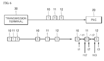
- the foregoing process will be described in more detail with reference to FIG. 6 .
- FIG. 6 is a diagram for illustrating a process of calculating interval information between reception times of sub-frames.
- the frame reception monitoring apparatus utilizes time information at a reception complete time point of a first sub-frame 10 of the plurality of sub-frames 10, 11 and 12 and time information at a reception start time point of a second sub-frame 11 of the plurality of sub-frames to calculate interval information between reception times of the first sub-frame 10 and the second sub-frame 11.
- the frame reception monitoring apparatus may substitute time information t2 at a reception complete time point of the second sub-frame 11 as determined based on the timestamp of the second sub-frame 11, a communication rate, and a length of the second sub-frame 11 for the Equation 1 to calculate a reception start time point ht2 of the second sub-frame 11.
- the frame reception monitoring apparatus may utilize the time information t1 at the reception complete time point of the first sub-frame 10 and the time information ht2 at the reception start time point of the second sub-frame 11 as determined by Equation 1, thereby calculating interval information ⁇ t1 between reception times of the first sub-frame 10 and the current sub-frame.
- the frame reception monitoring apparatus utilizes time information at a reception complete time point of a second sub-frame 11 of the plurality of sub-frames 10, 11 and 12 and time information at a reception start time point of a third sub-frame 12 of the plurality of sub-frames to calculate interval information between reception times of the second sub-frame 11 and the third sub-frame 12.
- the frame reception monitoring apparatus utilizes a timestamp of the second sub-frame 11 to determine time information at the reception complete time point of the second sub-frame 11. Further, the frame reception monitoring apparatus calculates the time information at the reception start time point of the third sub-frame 12 by using the above Equation 1.
- time information ht3 at a reception start time point of the third sub-frame 12 can be calculated.
- the frame reception monitoring apparatus may utilize the time information t2 at the reception complete time point of the second sub-frame 11 and the time information ht3 at the reception start time point of the third sub-frame 12 as determined by Equation 1, thereby calculating interval information ⁇ t2 between reception times of the second sub-frame 11 and the third sub-frame 12.
- FIG. 7 is an exemplary view displaying interval information between reception times of a plurality of sub-frames on a frame monitor.
- a plurality of sub-frames constituting one frame is each received into the reception buffer at certain time intervals and then the frame reception monitoring apparatus assigns timestamps to the sub-frames when allowing the sub-frames entered into the reception buffer to be stored on the temporal buffer and thereafter allows the sub-frames to be stored on the temporal buffer.
- the frame reception monitoring apparatus displays the timestamps assigned to the sub-frames on an application such as a frame monitor. Accordingly, a user can advantageously confirm that serial communications are exactly operated pursuant to an inter-sub-frames timeout time that he/she has set.
- the user may learn that time information at a reception complete time point of sub-frames 11 22 33 is 10021 ⁇ s by using a timestamp 10021 ⁇ s, as denoted by 710, of the sub-frames 11 22 33. Further, the user may learn that time information at a reception complete time point of sub-frames 44 55 66 is 10022 ⁇ s by using a timestamp 10022 ⁇ s, as denoted by 720, of the sub-frames 44 55 66.
- FIG. 8 is a diagram for illustrating the frame reception monitoring process based on a predetermined inter-sub-frames timeout time. On embodiment of FIG. 8 relates to an embodiment in which a frame reception can be monitored when an inter-sub-frames timeout time has been set to be 0.
- the frame reception monitoring apparatus receives a plurality of sub-frames constituting one frame through the communication module at certain time intervals.
- the frame reception monitoring apparatus allows the plurality of sub-frames to be respectively entered into the reception buffer 120.
- the frame reception monitoring apparatus assigns timestamps to the sub-frames entered into the reception buffer 120 and thereafter directly provides them to the service buffer 140 without passing through the temporal buffer 130 ( FIG. 2 ) because the inter-sub-frames timeout time has been set to be 0.
- the frame reception monitoring apparatus receives a first sub-frame of the plurality of sub-frames constituting one frame through the communication module and allows it to be entered into the reception buffer 120. And, the frame reception monitoring apparatus assigns a timestamp to the first sub-frame entered into the reception buffer 120 and thereafter directly provides it to the service buffer 140 without passing through the temporal buffer 130.
- the present disclosure assigns timestamps to sub-frames received by a transmission terminal at certain time intervals and stores them, so that interval information between reception times of the sub-frames can be advantageously calculated using a timestamp of a corresponding sub-frame.
- the present disclosure can control intervals between sub-frames, which would be recognized to be one frame, according to interval information between reception times of the sub-frames, calculated using the timestamps of the sub-frames, to control a combination of the sub-frames, and therefore, can advantageously be in a smooth communication with any types of serial communications instruments.
Landscapes
- Engineering & Computer Science (AREA)
- Theoretical Computer Science (AREA)
- Computer Networks & Wireless Communication (AREA)
- Signal Processing (AREA)
- Physics & Mathematics (AREA)
- General Physics & Mathematics (AREA)
- General Engineering & Computer Science (AREA)
- Computer Security & Cryptography (AREA)
- Communication Control (AREA)
- Mobile Radio Communication Systems (AREA)
- Information Transfer Systems (AREA)
- Health & Medical Sciences (AREA)
- Cardiology (AREA)
- General Health & Medical Sciences (AREA)
- Small-Scale Networks (AREA)
Abstract
Description
- Embodiments of the present disclosure relate to a frame reception monitoring method in serial communications.
- In serial communications, a transmission terminal divides one frame into a plurality of sub-frames to transmit them to a Programmable Logic Controller (PLC) at certain time intervals. At this time, the transmission terminal transmits sub-frames to the PLC through buffers, and the number of sub-frames differs depending on the size of the buffers.
- For example, if the number of sub-frames constituting one frame is three (3) and the size of a buffer is three (3), then the transmission terminal may simultaneously transmit the three sub-frames to the PLC through the buffer. In the above case, the transmission terminal may transmit a plurality of, i.e., three, sub-frames at a time to the PLC through the buffer by the size of the buffer, and hence its transmission rate is high. However, a UART controller with which such a buffer is equipped is disadvantageously expensive.
- For another example, if the number of sub-frames constituting one frame is three (3) and the size of a buffer is one (1), then the transmission terminal may transmit a first sub-frame to the PLC through the buffer. After completing the transmission of the first sub-frame, it may transmit a second sub-frame to the PLC through the buffer. Then, after completing the transmission of the second sub-frame, it may transmit a third sub-frame to the PLC through the buffer. In the above case, the transmission terminal may transmit a plurality of, i.e., three, sub-frames individually to the PLC through the buffer and hence its transmission rate is low. However, a UART controller with which such a buffer is equipped is advantageously cheap.
- Nonetheless, in the above example, there is a problem that the PLC may recognize each of the first, second and third sub-frames to be different frames in case where a difference time between reception times of the first sub-frame and the second sub-frame is not less than a certain time (e.g., 3.5 char time) or a difference time between reception times of the second sub-frame and the third sub-frame is not less than a certain time.
- In this case, since the recognized frame is different from a subject frame which is meant to be received, the recognized frame is discarded and as a result a reception process is not done. As such, the PLC has a problem that it is difficult to keep the compatibility and achieve a smooth communication because various types of unit instruments execute transmissions in respective formats.
- It is an aspect of the present disclosure to provide a frame reception monitoring method in serial communications which may assign timestamps to sub-frames received by a transmission terminal at certain time intervals and stores them, so that interval information between reception times of the sub-frames can be calculated using a timestamp of a corresponding sub-frame.
- It is another aspect of the present disclosure to provide a frame reception monitoring method in serial communications which may control intervals between sub-frames, which would be recognized to be one frame, according to interval information between reception times of the sub-frames, calculated using the timestamps of the sub-frames, to control a combination of the sub-frames, and therefore, can be in a smooth communication with any types of serial communications instruments.
- Other objects of the present disclosure are not limited to the above-described object and other objects and advantages can be appreciated by the following description described with reference to the embodiments of the present disclosure. Further, it will be easily appreciated that the objects and advantages of the present invention can be realized by means and a combination thereof recited in the appended claims.
- In accordance with one aspect of the present invention, the frame reception monitoring method in serial communications includes: when a plurality of sub-frames constituting a frame is each entered into a reception buffer at certain time intervals, allowing the respective sub-frames to be stored on a temporal buffer; allowing the plurality of sub-frames stored on the temporal buffer to be entered into a service buffer within a predetermined inter-sub-frames time-out time; using the plurality of sub-frames entered into the service buffer to generate a combined frame; and using the combined frame to execute a control.
- As described above, the present disclosure assigns timestamps to sub-frames received by a transmission terminal at certain time intervals and stores them, so that interval information between reception times of the sub-frames can be advantageously calculated using a timestamp of a corresponding sub-frame.
- Further, the present disclosure can control intervals between sub-frames, which would be recognized to be one frame, according to interval information between reception times of the sub-frames, calculated using the timestamps of the sub-frames, to control a combination of the sub-frames, and therefore, can advantageously be in a smooth communication with any types of serial communications instruments.
-
-
FIG. 1 is a diagram for illustrating frame transmission/reception processes in a UART controller. -
FIG. 2 is a flowchart for illustrating a frame reception monitoring method in serial communications according to one embodiment of the present disclosure. -
FIG. 3 is a block diagram for illustrating an internal structure of a frame reception monitoring apparatus according to one embodiment of the present disclosure. -
FIG. 4 is a diagram for illustrating a frame reception monitoring process according to one embodiment of the present disclosure. -
FIG. 5 is a diagram for illustrating the frame reception monitoring process ofFIG. 4 in more detail. -
FIG. 6 is a diagram for illustrating a process of calculating interval information between reception times of sub-frames. -
FIG. 7 is an exemplary view displaying interval information between reception times of a plurality of sub-frames on a frame monitor. -
FIG. 8 is a diagram for illustrating the frame reception monitoring process based on a predetermined inter-sub-frames timeout time. - The above objects, features and advantages will become apparent from the detailed description with reference to the accompanying drawings. Embodiments are described in sufficient detail to enable those skilled in the art in the art to easily practice the technical idea of the present disclosure. Detailed disclosures of well known functions or configurations may be omitted in order not to unnecessarily obscure the gist of the present disclosure. Hereinafter, embodiments of the present disclosure will be described in detail with reference to the accompanying drawings. Throughout the drawings, like reference numerals refer to like elements.
-
FIG. 1 is a diagram for illustrating frame transmission/reception processes in a UART controller. - Referring to
FIG. 1 , atransmission terminal 30 divides one frame into a plurality of sub-frames to transmit them to aPLC 20 at specific time intervals. At this time, thetransmission terminal 30 transmits different numbers of sub-frames to thePLC 20 through a corresponding buffer, the number of sub-frames depending on the size of the corresponding buffer. - For example, if the number of sub-frames constituting one frame is 3(three) and the size of a buffer is 3(three), then the
transmission terminal 30 may simultaneously transmit the three sub-frames to thePLC 20 through the buffer. In the above case, thetransmission terminal 30 may transmit a plurality of, i.e., three, sub-frames at a time to thePLC 20 through the buffer because the size of the buffer is large, and hence its transmission rate is high. However, a UART controller with which such a buffer is equipped is disadvantageously expensive. - For another example, if the number of sub-frames constituting one frame is 3(three) and the size of a buffer is 1(one), then the
transmission terminal 30 may transmit a first sub-frame to thePLC 20 through the buffer. After completing the transmission of the first sub-frame, it may transmit a second sub-frame to thePLC 20 through the buffer. Then, after completing the transmission of the second sub-frame, it may transmit a third sub-frame to thePLC 20 through the buffer. In the above case, the transmission terminal may transmit a plurality of, i.e., three, sub-frames individually to thePLC 20 through the buffer and hence its transmission rate is low. However, a UART controller with which such a buffer is equipped is advantageously cheap. - Nonetheless, in the above example, there is a problem that the
PLC 20 may recognize each of the first, second and third sub-frames to be different frames in case where a difference time between reception times of the first sub-frame and the second sub-frame is not less than a certain time (e.g., 3.5 char time) or a difference time between reception times of the second sub-frame and the third sub-frame is not less than a certain time. - That is, when transmitting each of the first to third sub-frames to the
PLC 20 at certain time intervals, thetransmission terminal 30 anticipates that thePLC 20 recognizes each of the first, second and third sub-frames to be one frame as in (a) ofFIG. 1 . - However, when a difference time between reception times of the first sub-frame and the second sub-frame is not less than a certain time or a difference time between reception times of the second sub-frame and the third sub-frame is not less than a certain time, the
PLC 20 recognizes each of the first, second and third sub-frames to be different frames as in (b) ofFIG. 1 . - In this case, since the recognized frame is different from a subject frame which is meant to be received, the recognized frame is discarded and as a result a reception process is not done. As such, the PLC has a problem that it is difficult to keep the compatibility and achieve a smooth communication because various types of unit instruments execute transmissions in respective formats.
-
FIG. 2 is a flowchart for illustrating a frame reception monitoring method in serial communications according to one embodiment of the present disclosure. - Referring to
FIG. 2 , when a plurality of sub-frames constituting a frame is each entered into a reception buffer at certain time intervals (Step S210), a frame reception monitoring apparatus stores a corresponding sub-frame on a temporal buffer (Step S220). - At this time, the frame reception monitoring apparatus assigns timestamps to the sub-frames and thereafter stores the sub-frames on the temporal buffer when storing the sub-frames entered into the reception buffer on the temporal buffer.
- The reason of assigning the timestamps to the sub-frames as described above is to utilize the timestamps assigned to the sub-frames to calculate interval information between reception times of the sub-frames, thereby determining an inter-sub-frames time-out time. The process of determining the inter-sub-frames time-out time will be described below in more detail.
- Hereinafter, the process of respectively assigning timestamps to a plurality of sub-frames will be described. When the plurality of sub-frames is received into the reception buffer at certain time intervals, the frame reception monitoring apparatus utilizes time information at reception complete time points of the respective sub-frames, to assign a timestamp to a corresponding sub-frame.
- For example, when a second sub-frame of the a plurality of sub-frames is received into the reception buffer, the frame reception monitoring apparatus utilizes time information, 1200µs, at a reception complete time point of the second sub-frame, to assign a timestamp 1200µs to the second sub-frame.
- The frame reception monitoring apparatus allows the plurality of sub-frames stored on the temporal buffer to be entered into a service buffer during a predetermined inter-sub-frames time-out time (Step S230).
- At this time, the reason of previously determining the inter-sub-frames time-out time is to determine a time point when sub-frames transmitted from the transmission terminal can be recognized to be one frame. That is, the inter-sub-frames time-out time is previously determined in order to recognize the first sub-frame to any sub-frames received across certain time points as one frame.
- Accordingly, the present disclosure can utilize the predetermined inter-sub-frames time-out time to recognize sub-frames stored on the temporal buffer during a specified time period to be one frame.
- However, determining the inter-sub-frames time-out time to be too short may cause the inter-sub-frames time-out time to expire before all of the sub-frames constituting the one frame are stored on the temporal buffer through the reception buffer.
- For example, the inter-sub-frames time-out time may expire when sub-frames A, B and C was received although a frame is constituted of sub-frames A, B, C, D and E. In this case, even though the sub-frames A, B and C are used to generate a combined frame, the combined frame is discarded since it is different from a subject frame which is meant to be received.
- On the contrary, determining the inter-sub-frames time-out time to be too long may cause all of the sub-frames constituting the one frame to pass through the reception buffer and then are stored on the temporal buffer. However, because the predetermined inter-sub-frames time-out time does not expire yet, this has a problem that it should wait until the predetermined inter-sub-frames time-out time expires.
- For example, all of the sub-frames A, B, C, D and E constituting one frame may be received. At this time, if the predetermined inter-sub-frames time-out time is left, then it should wait until the predetermined inter-sub-frames time-out time expires.
- Therefore, the present disclosure can utilize interval information between reception times of a plurality of sub-frames constituting one frame to previously determine an inter-sub-frames time-out time, thereby preventing the mentioned-above problem.
- Hereinafter, a process of utilizing timestamps of a plurality of sub-frames to calculate interval information between reception times of the sub-frames will be described.
- The frame reception monitoring apparatus utilizes time information at a reception complete time point of a first sub-frame of the plurality of sub-frames and time information at a reception start time point of a second sub-frame of the plurality of sub-frames to calculate interval information between reception times of the first sub-frame and the second sub-frame.
- At this time, the frame reception monitoring apparatus utilizes a timestamp of the first sub-frame to determine time information at the reception complete time point of the first sub-frame. However, the frame reception monitoring apparatus cannot know the time information at the reception start time point of the second sub-frame. Hence, the frame reception monitoring apparatus utilizes time information at a reception complete time point of the second sub-frame, a length of the second sub-frame, and a communication state to trace back time information at the reception start time point of the second sub-frame.
- Then, the frame reception monitoring apparatus may utilize the time information at the reception complete time point of the first sub-frame and the time information at the reception start time point of the second sub-frame as determined by the described-above process, thereby calculating interval information between reception times of the first sub-frame and the second sub-frame.
- Interval information between reception times of the plurality of sub-frames may be known by repeatedly performing the foregoing process. Further, combination of sub-frames can be controlled by utilizing such interval information to previously determine an inter-sub-frames time-out time, so that the smooth communication with any types of serial communications instruments can be achieved.
- The frame reception monitoring apparatus utilizes a plurality of sub-frames entered into the service buffer to generate the combined frame (Step S240), and checks whether the combined frame is identical to the subject frame meant to be received (Step S250).
- In response to the combined frame being identical to the subject frame meant to be received (Step S250), the frame reception monitoring apparatus utilizes the combined frame to execute a control (Step S260).
-
FIG. 3 is a block diagram for illustrating an internal structure of a frame reception monitoring apparatus according to one embodiment of the present disclosure. - Referring to
FIG. 3 , the frame reception monitoring apparatus includes acommunications module 110, areception buffer 120, atemporal buffer 130, aservice buffer 140, and acontrol module 150. - The
communications module 110 receives a plurality of sub-frames, which constitutes one frame, at certain time intervals. Thereafter, thecontrol module 150 allows each of the plurality of sub-frames received through thecommunications module 110 to be entered into thereception buffer 120. Thecontrol module 150 assigns timestamps to the sub-frames entered into thereception buffer 120 and then allows the sub-frames to be moved to thetemporal buffer 130. - That is, the
control module 150 utilizes time information at reception complete time points of the respective sub-frames entered into thereception buffer 120, to assign a timestamp to a corresponding sub-frame and then allows the sub-frame to be moved to thetemporal buffer 120. - The reason of assigning the timestamps to the sub-frames as described above is to utilize the timestamps assigned to the sub-frames to calculate interval information between reception times of the sub-frames, thereby determining an inter-sub-frames time-out time. That is, the inter-sub-frames time-out time is previously determined in order to recognize the first sub-frame to any sub-frames received across certain time points as one frame.
- The
control module 150 allows the plurality of sub-frames stored on thetemporal buffer 130 to be entered into theservice buffer 140 within a predetermined inter-sub-frames time-out time. - At this time, the reason of previously determining the inter-sub-frames time-out time is to determine a time point when sub-frames transmitted from the transmission terminal can be recognized to be one frame.
- Accordingly, the present disclosure can utilize the predetermined inter-sub-frames time-out time to recognize sub-frames stored on the temporal buffer during a specified time period to be one frame.
- However, setting the inter-sub-frames time-out time to be too short may cause the predetermined inter-sub-frames time-out time to expire before all of the sub-frames constituting the one frame are stored on the temporal buffer through the reception buffer.
- On the contrary, setting the predetermined inter-sub-frames time-out time to be too long may cause all of the sub-frames constituting the one frame to pass through the reception buffer and then be stored on the temporal buffer. However, because the predetermined inter-sub-frames time-out time does not expire yet, this has a problem that it should wait until the predetermined inter-sub-frames time-out time expires.
- Therefore, the present disclosure can utilize interval information between reception times of a plurality of sub-frames constituting one frame to previously determine the inter-sub-frames time-out time, thereby preventing the mentioned-above problem.
- To do so, the
control module 150 utilizes time information at a reception complete time point, which is determined based on a timestamp of a current sub-frame, of a previous sub-frame, a length of the current frame, and a communication rate to calculate time information at a reception start time point of the current sub-frame. - Then, the
control module 150 may utilize the time information at the reception complete time point, which is determined based on a timestamp of the previous sub-frame, of the previous sub-frame and the time information at the reception start time point of the current sub-frame as determined by the described-above process, thereby calculating interval information between reception times of the previous sub-frame and the current sub-frame. - Time intervals between a plurality of sub-frames may be known by repeatedly performing the foregoing process. Further, combination of sub-frames can be controlled by utilizing such interval information to determine an inter-sub-frames time-out time, so that the smooth communication with any types of serial communications instruments can be achieved.
- The
control module 150 utilizes a plurality of sub-frames entered into the service buffer to generate the combined frame, and checks whether the combined frame is identical to the subject frame meant to be received. -
FIG. 4 is a diagram for illustrating a frame reception monitoring process according to one embodiment of the present disclosure. - Referring to
FIGS. 3 and4 , the frame reception monitoring apparatus sequentially receives a plurality of sub-frames, which constitutes one frame, through thecommunications module 110 to allow them to be entered into thereception buffer 120. The frame reception monitoring apparatus allows the sub-frames entered into thereception buffer 120 to be moved to thetemporal buffer 130. - At this time, the frame reception monitoring apparatus assigns timestamps to the sub-frames and then stores the sub-frames on the
temporal buffer 130 when storing the sub-frames received into thereception buffer 120 on thetemporal buffer 130. - The reason of assigning the timestamps to the sub-frames as described above is to utilize the timestamps assigned to the sub-frames to calculate interval information between reception times of the sub-frames, thereby determining an inter-sub-frames time-out time.
- That is, combination of sub-frames can be controlled by utilizing the interval information between reception times of a plurality of sub-frames to previously determine an inter-sub-frames time-
out time 30, so that the smooth communication with any types of serial communications instruments can be achieved. - The
control module 150 allows the plurality of sub-frames stored on thetemporal buffer 130 to be entered into theservice buffer 140 during the predetermined inter-sub-frames time-out time 30. Then, thecontrol module 150 utilizes the plurality of sub-frames entered into theservice buffer 140 to generate the combined frame, and executes the control by using the combined frame when the combined frame is identical to the subject frame meant to be received. -
FIG. 5 is a diagram for illustrating the frame reception monitoring process ofFIG. 4 in more detail. - Referring to
FIGS. 3 and5 , the frame reception monitoring apparatus receives afirst sub-frame 21, which constitutes a portion of one frame, through thecommunications module 110. The frame reception monitoring apparatus allows the receivedfirst sub-frame 21 to be entered into thereception buffer 120 and then thefirst sub-frame 21 entered into thereception buffer 120 to be stored on thetemporal buffer 130. - At this time, the frame reception monitoring apparatus utilize time information at a reception complete time point of the
first sub-frame 21 to assign a timestamp to thefirst sub-frame 21 and then allows thefirst sub-frame 21 to be stored on thetemporal buffer 130 when storing thefirst sub-frame 21 received into thereception buffer 120 on thetemporal buffer 130. As inFIG. 5 , it may utilize time information 2100µs at the reception complete time point of thefirst sub-frame 21 to assign a timestamp 2100µs to thefirst sub-frame 21. - Then, the frame reception monitoring apparatus receives a
second sub-frame 22, which constitutes a portion of one frame, through thecommunications module 110. The frame reception monitoring apparatus allows the second receivedsub-frame 22 to be entered into thereception buffer 120 and then thesecond sub-frame 22 entered into thereception buffer 120 to be stored on thetemporal buffer 130. - At this time, the frame reception monitoring apparatus utilizes time information at a reception complete time point of the
second sub-frame 22 to assign a timestamp to thesecond sub-frame 22 and then allows thesecond sub-frame 22 to be stored on thetemporal buffer 130 when storing thesecond sub-frame 22 received into thereception buffer 120 on thetemporal buffer 130. As inFIG. 5 , it may utilize time information 3100µs at the reception complete time point of thesecond sub-frame 22 to assign a timestamp 3100µs to thesecond sub-frame 22. - Then, the frame reception monitoring apparatus allows the
first sub-frame 21 and thesecond sub-frame 22 stored on the temporal buffer to be entered into theservice buffer 140 within a predetermined inter-sub-frames time-out time 2000µs. Theservice buffer 140 may use thefirst sub-frame 21 and thesecond sub-frame 22 to generate a combinedframe 23. - The present disclosure utilizes the respective timestamps of the
first sub-frame 21 and thesecond sub-frame 22 to calculate interval information between reception times of thefirst sub-frame 21 and thesecond sub-frame 22. Then, the present disclosure may utilize the calculated interval information to determine an inter-sub-frames time-out time. - However, in order to calculate interval information between reception times of a plurality of sub-frames, time information at the respective reception start time points of the plurality of sub-frames should be known. Nonetheless, timestamps assigned to the respective sub-frames indicate only reception complete time points of the sub-frames.
- Therefore, the present disclosure traces back and calculates time information at a reception start time point of a current frame. Next, it may utilize the time information at the reception complete time point, which is determined based on a timestamp of a previous sub-frame, of the previous sub-frame and the time information at the reception start time point of the current sub-frame, thereby calculating interval information between reception times of the previous sub-frame and the current sub-frame. Hereinafter, the foregoing process will be described in more detail with reference to
FIG. 6 . -
FIG. 6 is a diagram for illustrating a process of calculating interval information between reception times of sub-frames. - Referring to
FIG. 6 , the frame reception monitoring apparatus utilizes time information at a reception complete time point of afirst sub-frame 10 of the plurality ofsub-frames second sub-frame 11 of the plurality of sub-frames to calculate interval information between reception times of thefirst sub-frame 10 and thesecond sub-frame 11. - At this time, the frame reception monitoring apparatus utilizes a timestamp of the
first sub-frame 10 to determine time information at the reception complete time point of thefirst sub-frame 10. Further, the frame reception monitoring apparatus calculates the time information at the reception start time point of thesecond sub-frame 11 by using the following Equation 1:
- HT: Time information at a reception complete time point of a first bit of a second or more sub-frame according to a communication rate
- T: Time information at a reception complete time point of a corresponding sub-frame determined based on a timestamp assigned to a corresponding the sub-frame
- The frame reception monitoring apparatus may substitute time information t2 at a reception complete time point of the
second sub-frame 11 as determined based on the timestamp of thesecond sub-frame 11, a communication rate, and a length of thesecond sub-frame 11 for theEquation 1 to calculate a reception start time point ht2 of thesecond sub-frame 11. - Then, the frame reception monitoring apparatus may utilize the time information t1 at the reception complete time point of the
first sub-frame 10 and the time information ht2 at the reception start time point of thesecond sub-frame 11 as determined byEquation 1, thereby calculating interval information Δt1 between reception times of thefirst sub-frame 10 and the current sub-frame. - Further, the frame reception monitoring apparatus utilizes time information at a reception complete time point of a
second sub-frame 11 of the plurality ofsub-frames third sub-frame 12 of the plurality of sub-frames to calculate interval information between reception times of thesecond sub-frame 11 and thethird sub-frame 12. - At this time, the frame reception monitoring apparatus utilizes a timestamp of the
second sub-frame 11 to determine time information at the reception complete time point of thesecond sub-frame 11. Further, the frame reception monitoring apparatus calculates the time information at the reception start time point of thethird sub-frame 12 by using theabove Equation 1. - That is, by using the
above Equation 1 similarly as the process of determining the time information at the reception start time point of thesecond sub-frame 11, time information ht3 at a reception start time point of thethird sub-frame 12 can be calculated. - Then, the frame reception monitoring apparatus may utilize the time information t2 at the reception complete time point of the
second sub-frame 11 and the time information ht3 at the reception start time point of thethird sub-frame 12 as determined byEquation 1, thereby calculating interval information Δt2 between reception times of thesecond sub-frame 11 and thethird sub-frame 12. -
FIG. 7 is an exemplary view displaying interval information between reception times of a plurality of sub-frames on a frame monitor. - Referring to
FIG. 7 , a plurality of sub-frames constituting one frame is each received into the reception buffer at certain time intervals and then the frame reception monitoring apparatus assigns timestamps to the sub-frames when allowing the sub-frames entered into the reception buffer to be stored on the temporal buffer and thereafter allows the sub-frames to be stored on the temporal buffer. - Then, the frame reception monitoring apparatus displays the timestamps assigned to the sub-frames on an application such as a frame monitor. Accordingly, a user can advantageously confirm that serial communications are exactly operated pursuant to an inter-sub-frames timeout time that he/she has set.
- For example, the user may learn that time information at a reception complete time point of
sub-frames 11 22 33 is 10021µs by using a timestamp 10021µs, as denoted by 710, of thesub-frames 11 22 33. Further, the user may learn that time information at a reception complete time point ofsub-frames 44 55 66 is 10022µs by using a timestamp 10022µs, as denoted by 720, of thesub-frames 44 55 66. -
FIG. 8 is a diagram for illustrating the frame reception monitoring process based on a predetermined inter-sub-frames timeout time. On embodiment ofFIG. 8 relates to an embodiment in which a frame reception can be monitored when an inter-sub-frames timeout time has been set to be 0. - Referring to
FIG. 8 , the frame reception monitoring apparatus receives a plurality of sub-frames constituting one frame through the communication module at certain time intervals. The frame reception monitoring apparatus allows the plurality of sub-frames to be respectively entered into thereception buffer 120. - However, the frame reception monitoring apparatus assigns timestamps to the sub-frames entered into the
reception buffer 120 and thereafter directly provides them to theservice buffer 140 without passing through the temporal buffer 130 (FIG. 2 ) because the inter-sub-frames timeout time has been set to be 0. - For example, the frame reception monitoring apparatus receives a first sub-frame of the plurality of sub-frames constituting one frame through the communication module and allows it to be entered into the
reception buffer 120. And, the frame reception monitoring apparatus assigns a timestamp to the first sub-frame entered into thereception buffer 120 and thereafter directly provides it to theservice buffer 140 without passing through thetemporal buffer 130. - As described above, the present disclosure assigns timestamps to sub-frames received by a transmission terminal at certain time intervals and stores them, so that interval information between reception times of the sub-frames can be advantageously calculated using a timestamp of a corresponding sub-frame.
- Further, the present disclosure can control intervals between sub-frames, which would be recognized to be one frame, according to interval information between reception times of the sub-frames, calculated using the timestamps of the sub-frames, to control a combination of the sub-frames, and therefore, can advantageously be in a smooth communication with any types of serial communications instruments.
- The present disclosure described above may be variously substituted, altered, and modified by those skilled in the art to which the present invention pertains without departing from the scope and spirit of the present disclosure. Therefore, the present disclosure is not limited to the above-mentioned exemplary embodiments and the accompanying drawings.
Claims (10)
- A frame reception monitoring method in serial communications, the method comprising:when a plurality of sub-frames constituting a frame is each entered into a reception buffer (120) at certain time intervals, allowing the respective sub-frames to be stored on a temporal buffer (130);allowing the plurality of sub-frames stored on the temporal buffer (130) to be entered into a service buffer (140) within a predetermined inter-sub-frames time-out time (30);using the plurality of sub-frames entered into the service buffer (140) to generate a combined frame; andusing the combined frame to execute a control.
- The method according to claim 1, wherein when a plurality of sub-frames constituting a frame is each entered into a reception buffer at certain time intervals, allowing the respective sub-frames to be stored on a temporal buffer (130) includes assigning timestamps to the sub-frames and then allowing the sub-frames to be stored on the temporal buffer (130) when storing the sub-frames entered into the reception buffer (120) on the temporal buffer (130).
- The method according to claim 2, wherein assigning timestamps to the sub-frames and then allowing the sub-frames to be stored on the temporal buffer (130) includes utilizing time information at a reception complete time point of each of the sub-frames to assign a timestamp to a corresponding sub-frame when the plurality of sub-frames is each entered into the reception buffer (120).
- The method according to claim 2, further comprising:utilizing the timestamps respectively assigned to the sub-frames to calculate interval information between reception times of the sub-frames.
- The method according to claim 4, wherein utilizing the timestamps respectively assigned to the sub-frames to calculate interval information between reception times of the sub-frames includes utilizing time information at a reception complete time point of a first sub-frame of the plurality of sub-frames and time information at a reception start time point of a second sub-frame of the plurality of sub-frames to calculate interval information between reception times of the first sub-frame and the second sub-frame.
- The method according to claim 5, wherein calculating interval information between reception times of the first sub-frame and the second sub-frame includes utilizing a timestamp of the first sub-frame to determine time information at the reception complete time point of the first sub-frame.
- The method according to claim 5, wherein calculating interval information between reception times of the first sub-frame and the second sub-frame includes:utilizing a timestamp of the second sub-frame to determine time information at a reception complete time point of the second sub-frame; andutilizing the time information at the reception complete time point of the second sub-frame, a length of the second sub-frame, and a communication state to calculate time information at the reception start time point of the second sub-frame.
- The method according to claim 4, further comprising:utilizing the interval information between reception times of the plurality of sub-frames to determine the inter-sub-frames time-out time (30).
- The method according to claim 1, wherein using the combined frame to execute a control includes:determining whether the combined frame is identical to a subject frame meant to be received;if it is determined that the combined frame is identical to the subject frame, executing the control using the combined frame; andif it is determined that the combined frame is not identical to the subject frame, deleting the combined frame.
- The method according to claim 1, wherein the frame reception monitoring method is executed in a UART controller in serial communications.
Applications Claiming Priority (1)
| Application Number | Priority Date | Filing Date | Title |
|---|---|---|---|
| KR1020160000558A KR101785821B1 (en) | 2016-01-04 | 2016-01-04 | Method of monitoring frame receiving in serial communication |
Publications (2)
| Publication Number | Publication Date |
|---|---|
| EP3188423A1 true EP3188423A1 (en) | 2017-07-05 |
| EP3188423B1 EP3188423B1 (en) | 2021-03-10 |
Family
ID=57354091
Family Applications (1)
| Application Number | Title | Priority Date | Filing Date |
|---|---|---|---|
| EP16195531.5A Active EP3188423B1 (en) | 2016-01-04 | 2016-10-25 | Frame reception monitoring method in serial communications |
Country Status (6)
| Country | Link |
|---|---|
| US (1) | US10248588B2 (en) |
| EP (1) | EP3188423B1 (en) |
| JP (1) | JP6318223B2 (en) |
| KR (1) | KR101785821B1 (en) |
| CN (1) | CN107040335B (en) |
| ES (1) | ES2869969T3 (en) |
Cited By (1)
| Publication number | Priority date | Publication date | Assignee | Title |
|---|---|---|---|---|
| EP3539293A1 (en) * | 2016-11-09 | 2019-09-18 | Renesas Electronics Corporation | Communications network controller module |
Families Citing this family (1)
| Publication number | Priority date | Publication date | Assignee | Title |
|---|---|---|---|---|
| CN108306967B (en) * | 2018-01-31 | 2021-04-06 | 深圳市元征科技股份有限公司 | Data processing method and terminal |
Citations (2)
| Publication number | Priority date | Publication date | Assignee | Title |
|---|---|---|---|---|
| US5619681A (en) * | 1992-11-23 | 1997-04-08 | Zilog, Inc. | Delayed FIFO status for serial shift emulation |
| US5717870A (en) * | 1994-10-26 | 1998-02-10 | Hayes Microcomputer Products, Inc. | Serial port controller for preventing repetitive interrupt signals |
Family Cites Families (18)
| Publication number | Priority date | Publication date | Assignee | Title |
|---|---|---|---|---|
| JPH0242837A (en) * | 1988-08-02 | 1990-02-13 | Fujitsu Ltd | Control data output system |
| US5169681A (en) * | 1989-04-06 | 1992-12-08 | Kim Jae Duck | Method of producing an ornamental sticker without a separate cutting step |
| US5469545A (en) * | 1991-10-03 | 1995-11-21 | Compaq Computer Corp. | Expandable communication system with data flow control |
| JP3421191B2 (en) | 1996-04-23 | 2003-06-30 | 三菱電機株式会社 | Robot control device and data communication method thereof |
| JP3837857B2 (en) | 1997-08-14 | 2006-10-25 | ソニー株式会社 | Signal processing circuit |
| JP3637029B2 (en) | 2002-03-28 | 2005-04-06 | 三菱電機株式会社 | In-vehicle electronic control unit |
| JP2004351551A (en) | 2003-05-28 | 2004-12-16 | Seiko Epson Corp | Robot control device and robot control method |
| KR20050055919A (en) | 2003-12-09 | 2005-06-14 | 엘지전자 주식회사 | A processor access controller for a multi-processor system and the method thereof |
| JP2007038326A (en) | 2005-08-01 | 2007-02-15 | Toyota Motor Corp | Robot control system |
| WO2008015492A1 (en) * | 2006-08-02 | 2008-02-07 | Freescale Semiconductor, Inc. | A method for receiving and processing frames and a device having frame receiving and processing capabilities |
| KR101582695B1 (en) | 2010-01-18 | 2016-01-06 | 엘에스산전 주식회사 | System for monitoring a communication failure of power device based on ethernet and method therefor |
| US8705395B2 (en) * | 2010-06-15 | 2014-04-22 | Jds Uniphase Corporation | Method for time aware inline remote mirroring |
| JP5682233B2 (en) * | 2010-11-01 | 2015-03-11 | 富士通株式会社 | Analysis processing apparatus, analysis processing program, and analysis processing method |
| CN103069757B (en) | 2011-08-17 | 2015-07-22 | 华为技术有限公司 | Packet reassembly and resequence method, apparatus and system |
| US9131271B2 (en) * | 2011-11-02 | 2015-09-08 | Connected Lyfe | Systems and methods for real-time adaptation of multimedia data |
| KR101217607B1 (en) | 2012-04-18 | 2013-01-02 | 현대인프라코어 주식회사 | Industrial controller device capable of high speed serial communication with ultra low error rate and operation method thereof |
| KR101434422B1 (en) * | 2013-07-24 | 2014-08-26 | 전자부품연구원 | Method for improving network by modulating virtual link and the system thereof |
| CN104796652B (en) * | 2015-01-12 | 2017-11-03 | 北京瀚景锦河科技有限公司 | A kind of data transmission method and device that frame of video is transmitted based on SRIO |
-
2016
- 2016-01-04 KR KR1020160000558A patent/KR101785821B1/en active Active
- 2016-10-25 ES ES16195531T patent/ES2869969T3/en active Active
- 2016-10-25 EP EP16195531.5A patent/EP3188423B1/en active Active
- 2016-11-08 CN CN201610979961.0A patent/CN107040335B/en active Active
- 2016-11-14 JP JP2016221888A patent/JP6318223B2/en not_active Expired - Fee Related
- 2016-11-17 US US15/354,166 patent/US10248588B2/en active Active
Patent Citations (2)
| Publication number | Priority date | Publication date | Assignee | Title |
|---|---|---|---|---|
| US5619681A (en) * | 1992-11-23 | 1997-04-08 | Zilog, Inc. | Delayed FIFO status for serial shift emulation |
| US5717870A (en) * | 1994-10-26 | 1998-02-10 | Hayes Microcomputer Products, Inc. | Serial port controller for preventing repetitive interrupt signals |
Cited By (1)
| Publication number | Priority date | Publication date | Assignee | Title |
|---|---|---|---|---|
| EP3539293A1 (en) * | 2016-11-09 | 2019-09-18 | Renesas Electronics Corporation | Communications network controller module |
Also Published As
| Publication number | Publication date |
|---|---|
| CN107040335A (en) | 2017-08-11 |
| JP6318223B2 (en) | 2018-04-25 |
| CN107040335B (en) | 2020-04-14 |
| KR20170081471A (en) | 2017-07-12 |
| EP3188423B1 (en) | 2021-03-10 |
| JP2017123643A (en) | 2017-07-13 |
| US10248588B2 (en) | 2019-04-02 |
| KR101785821B1 (en) | 2017-10-16 |
| ES2869969T3 (en) | 2021-10-26 |
| US20180095907A1 (en) | 2018-04-05 |
Similar Documents
| Publication | Publication Date | Title |
|---|---|---|
| US9503964B2 (en) | Method and system for parallel transmission of plural types of wireless links | |
| US9634888B2 (en) | Method and system for transmitting data in parallel via wireless link and wired link | |
| US10383152B2 (en) | Random access procedure for machine type communication | |
| KR101948732B1 (en) | Control channel transmission for paging message coverage enhancement | |
| CN114257772B (en) | Data transmission adjustment method, device, computer equipment and readable storage medium | |
| CN107977290B (en) | MIPI loop test method and test system | |
| US20230254873A1 (en) | Feedback Information Transmission Method, Terminal and Network Device | |
| CN113078988A (en) | Method, device, equipment and medium for reporting channel state information | |
| EP3082282A1 (en) | Method for time synchronization | |
| US10248588B2 (en) | Frame reception monitoring method in serial communications | |
| CN114390657A (en) | Power determination method, device, terminal and readable storage medium | |
| KR20250086578A (en) | Active stylus detection method | |
| CN107317821A (en) | A kind of transmission method of view data, apparatus and system | |
| US20150181448A1 (en) | Mobile terminal test device and mobile terminal test method | |
| TWI599255B (en) | Pilot configuration method and device | |
| US20220171515A1 (en) | Touch display device and controller used in the same | |
| CN108769609B (en) | Video display method and device | |
| CN115150026A (en) | Information reporting method, device and terminal | |
| CN115267839B (en) | Signal monitoring method, device, system, electronic device and storage medium | |
| CN112312421B (en) | Cell configuration method and device in time division system | |
| CN104104685A (en) | Method and device for forwarding picture | |
| WO2024022251A1 (en) | Uplink transmission method and apparatus, and terminal and medium | |
| CN105025384B (en) | A kind of method and device of display channel | |
| CN106850134B (en) | Frame transmission method and device | |
| CN119165806A (en) | Battery simulator synchronization method, device and storage medium |
Legal Events
| Date | Code | Title | Description |
|---|---|---|---|
| PUAI | Public reference made under article 153(3) epc to a published international application that has entered the european phase |
Free format text: ORIGINAL CODE: 0009012 |
|
| STAA | Information on the status of an ep patent application or granted ep patent |
Free format text: STATUS: THE APPLICATION HAS BEEN PUBLISHED |
|
| AK | Designated contracting states |
Kind code of ref document: A1 Designated state(s): AL AT BE BG CH CY CZ DE DK EE ES FI FR GB GR HR HU IE IS IT LI LT LU LV MC MK MT NL NO PL PT RO RS SE SI SK SM TR |
|
| AX | Request for extension of the european patent |
Extension state: BA ME |
|
| STAA | Information on the status of an ep patent application or granted ep patent |
Free format text: STATUS: REQUEST FOR EXAMINATION WAS MADE |
|
| 17P | Request for examination filed |
Effective date: 20180102 |
|
| RBV | Designated contracting states (corrected) |
Designated state(s): AL AT BE BG CH CY CZ DE DK EE ES FI FR GB GR HR HU IE IS IT LI LT LU LV MC MK MT NL NO PL PT RO RS SE SI SK SM TR |
|
| STAA | Information on the status of an ep patent application or granted ep patent |
Free format text: STATUS: EXAMINATION IS IN PROGRESS |
|
| 17Q | First examination report despatched |
Effective date: 20200811 |
|
| REG | Reference to a national code |
Ref country code: DE Ref legal event code: R079 Ref document number: 602016053929 Country of ref document: DE Free format text: PREVIOUS MAIN CLASS: H04L0012931000 Ipc: G06F0013160000 |
|
| GRAP | Despatch of communication of intention to grant a patent |
Free format text: ORIGINAL CODE: EPIDOSNIGR1 |
|
| STAA | Information on the status of an ep patent application or granted ep patent |
Free format text: STATUS: GRANT OF PATENT IS INTENDED |
|
| RIC1 | Information provided on ipc code assigned before grant |
Ipc: H04L 12/801 20130101ALI20201016BHEP Ipc: H04L 12/861 20130101ALI20201016BHEP Ipc: G06F 13/42 20060101ALI20201016BHEP Ipc: G06F 13/16 20060101AFI20201016BHEP |
|
| INTG | Intention to grant announced |
Effective date: 20201118 |
|
| GRAS | Grant fee paid |
Free format text: ORIGINAL CODE: EPIDOSNIGR3 |
|
| GRAA | (expected) grant |
Free format text: ORIGINAL CODE: 0009210 |
|
| STAA | Information on the status of an ep patent application or granted ep patent |
Free format text: STATUS: THE PATENT HAS BEEN GRANTED |
|
| AK | Designated contracting states |
Kind code of ref document: B1 Designated state(s): AL AT BE BG CH CY CZ DE DK EE ES FI FR GB GR HR HU IE IS IT LI LT LU LV MC MK MT NL NO PL PT RO RS SE SI SK SM TR |
|
| REG | Reference to a national code |
Ref country code: GB Ref legal event code: FG4D |
|
| REG | Reference to a national code |
Ref country code: AT Ref legal event code: REF Ref document number: 1370606 Country of ref document: AT Kind code of ref document: T Effective date: 20210315 Ref country code: CH Ref legal event code: EP |
|
| REG | Reference to a national code |
Ref country code: IE Ref legal event code: FG4D |
|
| REG | Reference to a national code |
Ref country code: DE Ref legal event code: R096 Ref document number: 602016053929 Country of ref document: DE |
|
| REG | Reference to a national code |
Ref country code: LT Ref legal event code: MG9D |
|
| PG25 | Lapsed in a contracting state [announced via postgrant information from national office to epo] |
Ref country code: FI Free format text: LAPSE BECAUSE OF FAILURE TO SUBMIT A TRANSLATION OF THE DESCRIPTION OR TO PAY THE FEE WITHIN THE PRESCRIBED TIME-LIMIT Effective date: 20210310 Ref country code: GR Free format text: LAPSE BECAUSE OF FAILURE TO SUBMIT A TRANSLATION OF THE DESCRIPTION OR TO PAY THE FEE WITHIN THE PRESCRIBED TIME-LIMIT Effective date: 20210611 Ref country code: HR Free format text: LAPSE BECAUSE OF FAILURE TO SUBMIT A TRANSLATION OF THE DESCRIPTION OR TO PAY THE FEE WITHIN THE PRESCRIBED TIME-LIMIT Effective date: 20210310 Ref country code: NO Free format text: LAPSE BECAUSE OF FAILURE TO SUBMIT A TRANSLATION OF THE DESCRIPTION OR TO PAY THE FEE WITHIN THE PRESCRIBED TIME-LIMIT Effective date: 20210610 Ref country code: LT Free format text: LAPSE BECAUSE OF FAILURE TO SUBMIT A TRANSLATION OF THE DESCRIPTION OR TO PAY THE FEE WITHIN THE PRESCRIBED TIME-LIMIT Effective date: 20210310 Ref country code: BG Free format text: LAPSE BECAUSE OF FAILURE TO SUBMIT A TRANSLATION OF THE DESCRIPTION OR TO PAY THE FEE WITHIN THE PRESCRIBED TIME-LIMIT Effective date: 20210610 |
|
| REG | Reference to a national code |
Ref country code: AT Ref legal event code: MK05 Ref document number: 1370606 Country of ref document: AT Kind code of ref document: T Effective date: 20210310 |
|
| REG | Reference to a national code |
Ref country code: NL Ref legal event code: MP Effective date: 20210310 |
|
| PG25 | Lapsed in a contracting state [announced via postgrant information from national office to epo] |
Ref country code: SE Free format text: LAPSE BECAUSE OF FAILURE TO SUBMIT A TRANSLATION OF THE DESCRIPTION OR TO PAY THE FEE WITHIN THE PRESCRIBED TIME-LIMIT Effective date: 20210310 Ref country code: RS Free format text: LAPSE BECAUSE OF FAILURE TO SUBMIT A TRANSLATION OF THE DESCRIPTION OR TO PAY THE FEE WITHIN THE PRESCRIBED TIME-LIMIT Effective date: 20210310 Ref country code: LV Free format text: LAPSE BECAUSE OF FAILURE TO SUBMIT A TRANSLATION OF THE DESCRIPTION OR TO PAY THE FEE WITHIN THE PRESCRIBED TIME-LIMIT Effective date: 20210310 |
|
| PG25 | Lapsed in a contracting state [announced via postgrant information from national office to epo] |
Ref country code: NL Free format text: LAPSE BECAUSE OF FAILURE TO SUBMIT A TRANSLATION OF THE DESCRIPTION OR TO PAY THE FEE WITHIN THE PRESCRIBED TIME-LIMIT Effective date: 20210310 |
|
| REG | Reference to a national code |
Ref country code: ES Ref legal event code: FG2A Ref document number: 2869969 Country of ref document: ES Kind code of ref document: T3 Effective date: 20211026 |
|
| PG25 | Lapsed in a contracting state [announced via postgrant information from national office to epo] |
Ref country code: CZ Free format text: LAPSE BECAUSE OF FAILURE TO SUBMIT A TRANSLATION OF THE DESCRIPTION OR TO PAY THE FEE WITHIN THE PRESCRIBED TIME-LIMIT Effective date: 20210310 Ref country code: EE Free format text: LAPSE BECAUSE OF FAILURE TO SUBMIT A TRANSLATION OF THE DESCRIPTION OR TO PAY THE FEE WITHIN THE PRESCRIBED TIME-LIMIT Effective date: 20210310 Ref country code: AT Free format text: LAPSE BECAUSE OF FAILURE TO SUBMIT A TRANSLATION OF THE DESCRIPTION OR TO PAY THE FEE WITHIN THE PRESCRIBED TIME-LIMIT Effective date: 20210310 Ref country code: SM Free format text: LAPSE BECAUSE OF FAILURE TO SUBMIT A TRANSLATION OF THE DESCRIPTION OR TO PAY THE FEE WITHIN THE PRESCRIBED TIME-LIMIT Effective date: 20210310 |
|
| PG25 | Lapsed in a contracting state [announced via postgrant information from national office to epo] |
Ref country code: IS Free format text: LAPSE BECAUSE OF FAILURE TO SUBMIT A TRANSLATION OF THE DESCRIPTION OR TO PAY THE FEE WITHIN THE PRESCRIBED TIME-LIMIT Effective date: 20210710 Ref country code: PT Free format text: LAPSE BECAUSE OF FAILURE TO SUBMIT A TRANSLATION OF THE DESCRIPTION OR TO PAY THE FEE WITHIN THE PRESCRIBED TIME-LIMIT Effective date: 20210712 Ref country code: PL Free format text: LAPSE BECAUSE OF FAILURE TO SUBMIT A TRANSLATION OF THE DESCRIPTION OR TO PAY THE FEE WITHIN THE PRESCRIBED TIME-LIMIT Effective date: 20210310 Ref country code: SK Free format text: LAPSE BECAUSE OF FAILURE TO SUBMIT A TRANSLATION OF THE DESCRIPTION OR TO PAY THE FEE WITHIN THE PRESCRIBED TIME-LIMIT Effective date: 20210310 Ref country code: RO Free format text: LAPSE BECAUSE OF FAILURE TO SUBMIT A TRANSLATION OF THE DESCRIPTION OR TO PAY THE FEE WITHIN THE PRESCRIBED TIME-LIMIT Effective date: 20210310 |
|
| REG | Reference to a national code |
Ref country code: DE Ref legal event code: R097 Ref document number: 602016053929 Country of ref document: DE |
|
| PLBE | No opposition filed within time limit |
Free format text: ORIGINAL CODE: 0009261 |
|
| STAA | Information on the status of an ep patent application or granted ep patent |
Free format text: STATUS: NO OPPOSITION FILED WITHIN TIME LIMIT |
|
| PG25 | Lapsed in a contracting state [announced via postgrant information from national office to epo] |
Ref country code: DK Free format text: LAPSE BECAUSE OF FAILURE TO SUBMIT A TRANSLATION OF THE DESCRIPTION OR TO PAY THE FEE WITHIN THE PRESCRIBED TIME-LIMIT Effective date: 20210310 Ref country code: AL Free format text: LAPSE BECAUSE OF FAILURE TO SUBMIT A TRANSLATION OF THE DESCRIPTION OR TO PAY THE FEE WITHIN THE PRESCRIBED TIME-LIMIT Effective date: 20210310 |
|
| 26N | No opposition filed |
Effective date: 20211213 |
|
| PG25 | Lapsed in a contracting state [announced via postgrant information from national office to epo] |
Ref country code: SI Free format text: LAPSE BECAUSE OF FAILURE TO SUBMIT A TRANSLATION OF THE DESCRIPTION OR TO PAY THE FEE WITHIN THE PRESCRIBED TIME-LIMIT Effective date: 20210310 |
|
| PG25 | Lapsed in a contracting state [announced via postgrant information from national office to epo] |
Ref country code: IS Free format text: LAPSE BECAUSE OF FAILURE TO SUBMIT A TRANSLATION OF THE DESCRIPTION OR TO PAY THE FEE WITHIN THE PRESCRIBED TIME-LIMIT Effective date: 20210710 |
|
| REG | Reference to a national code |
Ref country code: CH Ref legal event code: PL |
|
| REG | Reference to a national code |
Ref country code: BE Ref legal event code: MM Effective date: 20211031 |
|
| PG25 | Lapsed in a contracting state [announced via postgrant information from national office to epo] |
Ref country code: MC Free format text: LAPSE BECAUSE OF FAILURE TO SUBMIT A TRANSLATION OF THE DESCRIPTION OR TO PAY THE FEE WITHIN THE PRESCRIBED TIME-LIMIT Effective date: 20210310 |
|
| PG25 | Lapsed in a contracting state [announced via postgrant information from national office to epo] |
Ref country code: LU Free format text: LAPSE BECAUSE OF NON-PAYMENT OF DUE FEES Effective date: 20211025 Ref country code: BE Free format text: LAPSE BECAUSE OF NON-PAYMENT OF DUE FEES Effective date: 20211031 |
|
| PG25 | Lapsed in a contracting state [announced via postgrant information from national office to epo] |
Ref country code: LI Free format text: LAPSE BECAUSE OF NON-PAYMENT OF DUE FEES Effective date: 20211031 Ref country code: CH Free format text: LAPSE BECAUSE OF NON-PAYMENT OF DUE FEES Effective date: 20211031 |
|
| PG25 | Lapsed in a contracting state [announced via postgrant information from national office to epo] |
Ref country code: IE Free format text: LAPSE BECAUSE OF NON-PAYMENT OF DUE FEES Effective date: 20211025 |
|
| PGFP | Annual fee paid to national office [announced via postgrant information from national office to epo] |
Ref country code: GB Payment date: 20220905 Year of fee payment: 7 |
|
| PGFP | Annual fee paid to national office [announced via postgrant information from national office to epo] |
Ref country code: ES Payment date: 20221114 Year of fee payment: 7 |
|
| PG25 | Lapsed in a contracting state [announced via postgrant information from national office to epo] |
Ref country code: HU Free format text: LAPSE BECAUSE OF FAILURE TO SUBMIT A TRANSLATION OF THE DESCRIPTION OR TO PAY THE FEE WITHIN THE PRESCRIBED TIME-LIMIT; INVALID AB INITIO Effective date: 20161025 |
|
| PG25 | Lapsed in a contracting state [announced via postgrant information from national office to epo] |
Ref country code: CY Free format text: LAPSE BECAUSE OF FAILURE TO SUBMIT A TRANSLATION OF THE DESCRIPTION OR TO PAY THE FEE WITHIN THE PRESCRIBED TIME-LIMIT Effective date: 20210310 |
|
| P01 | Opt-out of the competence of the unified patent court (upc) registered |
Effective date: 20230625 |
|
| PG25 | Lapsed in a contracting state [announced via postgrant information from national office to epo] |
Ref country code: MK Free format text: LAPSE BECAUSE OF FAILURE TO SUBMIT A TRANSLATION OF THE DESCRIPTION OR TO PAY THE FEE WITHIN THE PRESCRIBED TIME-LIMIT Effective date: 20210310 |
|
| GBPC | Gb: european patent ceased through non-payment of renewal fee |
Effective date: 20231025 |
|
| PG25 | Lapsed in a contracting state [announced via postgrant information from national office to epo] |
Ref country code: GB Free format text: LAPSE BECAUSE OF NON-PAYMENT OF DUE FEES Effective date: 20231025 |
|
| PG25 | Lapsed in a contracting state [announced via postgrant information from national office to epo] |
Ref country code: GB Free format text: LAPSE BECAUSE OF NON-PAYMENT OF DUE FEES Effective date: 20231025 |
|
| PG25 | Lapsed in a contracting state [announced via postgrant information from national office to epo] |
Ref country code: MT Free format text: LAPSE BECAUSE OF FAILURE TO SUBMIT A TRANSLATION OF THE DESCRIPTION OR TO PAY THE FEE WITHIN THE PRESCRIBED TIME-LIMIT Effective date: 20210310 |
|
| REG | Reference to a national code |
Ref country code: ES Ref legal event code: FD2A Effective date: 20241205 |
|
| PG25 | Lapsed in a contracting state [announced via postgrant information from national office to epo] |
Ref country code: ES Free format text: LAPSE BECAUSE OF NON-PAYMENT OF DUE FEES Effective date: 20231026 |
|
| PG25 | Lapsed in a contracting state [announced via postgrant information from national office to epo] |
Ref country code: ES Free format text: LAPSE BECAUSE OF NON-PAYMENT OF DUE FEES Effective date: 20231026 |
|
| PGFP | Annual fee paid to national office [announced via postgrant information from national office to epo] |
Ref country code: IT Payment date: 20250909 Year of fee payment: 10 |
|
| PGFP | Annual fee paid to national office [announced via postgrant information from national office to epo] |
Ref country code: FR Payment date: 20250909 Year of fee payment: 10 |
|
| PG25 | Lapsed in a contracting state [announced via postgrant information from national office to epo] |
Ref country code: TR Free format text: LAPSE BECAUSE OF FAILURE TO SUBMIT A TRANSLATION OF THE DESCRIPTION OR TO PAY THE FEE WITHIN THE PRESCRIBED TIME-LIMIT Effective date: 20210310 |
|
| PGFP | Annual fee paid to national office [announced via postgrant information from national office to epo] |
Ref country code: DE Payment date: 20250908 Year of fee payment: 10 |