EP3188367B1 - Verbesserung von wandlern mit an der oberfläche geführten volumenwellen - Google Patents
Verbesserung von wandlern mit an der oberfläche geführten volumenwellen Download PDFInfo
- Publication number
- EP3188367B1 EP3188367B1 EP16020513.4A EP16020513A EP3188367B1 EP 3188367 B1 EP3188367 B1 EP 3188367B1 EP 16020513 A EP16020513 A EP 16020513A EP 3188367 B1 EP3188367 B1 EP 3188367B1
- Authority
- EP
- European Patent Office
- Prior art keywords
- electrodes
- series
- transducer
- elementary
- electrode
- Prior art date
- Legal status (The legal status is an assumption and is not a legal conclusion. Google has not performed a legal analysis and makes no representation as to the accuracy of the status listed.)
- Active
Links
Images

Classifications
-
- H—ELECTRICITY
- H03—ELECTRONIC CIRCUITRY
- H03H—IMPEDANCE NETWORKS, e.g. RESONANT CIRCUITS; RESONATORS
- H03H9/00—Networks comprising electromechanical or electro-acoustic elements; Electromechanical resonators
- H03H9/02—Details
- H03H9/02228—Guided bulk acoustic wave devices or Lamb wave devices having interdigital transducers situated in parallel planes on either side of a piezoelectric layer
-
- H—ELECTRICITY
- H03—ELECTRONIC CIRCUITRY
- H03H—IMPEDANCE NETWORKS, e.g. RESONANT CIRCUITS; RESONATORS
- H03H9/00—Networks comprising electromechanical or electro-acoustic elements; Electromechanical resonators
- H03H9/0023—Networks for transforming balanced signals into unbalanced signals and vice versa, e.g. baluns, or networks having balanced input and output
- H03H9/0095—Networks for transforming balanced signals into unbalanced signals and vice versa, e.g. baluns, or networks having balanced input and output using bulk acoustic wave devices
Definitions
- Such a transducer makes it possible to convert an electrical signal having a working frequency ft, ft corresponding to an acoustic wavelength l for which the transducer is sized, into a volume wave guided on the surface of the substrate and vice versa.
- the elementary transducers of a transducer according to D1 are produced on an insulating substrate covered with a ground plane of conductive material; they each comprise a bar made of piezoelectric material covered with a conductive upper electrode, the ground plane forming a lower electrode common to all the transducers; the upper electrodes of two adjacent elementary transducers must be fed by opposite potentials + V, - V, the ground plane forming an electrical reference, to allow the displacement of the volume waves.
- Each elementary transducer having its own lower electrode it becomes possible to feed the transducer by a referenced voltage source, producing a single excitation potential with respect to a mass, while obtaining a good coefficient of acoustic coupling.
- a midpoint transformer to realize a differential source.
- the connection for the power supply of a transducer according to the invention is thus greatly simplified.
- the lower electrode of an elementary transducer is electrically connected to the upper electrode of the preceding elementary transducer and to the upper electrode of the next elementary transducer and the upper electrode of a Elementary transducer is electrically connected to the lower electrode of the previous elementary transducer and the lower electrode of the next elementary transducer.
- two adjacent elementary transducers are connected head-to-tail so that the potential difference between the electrodes of an elementary transducer is automatically reversed from the potential difference between the electrodes of a previous elementary transducer or the electrodes of an elementary transducer.
- the invention also relates to methods of manufacturing transducers according to the invention, methods detailed in the description below.
- the lower electrodes 22, 22a, 22b, ..., 2, 22c, 32, 32a, 32b, ..., 32c and the connecting conductors 41, 42 associated are made simultaneously by 1. appropriate masking of the upper face of the substrate and 2. deposition of a layer of electrically conductive material of thickness e2 much smaller than the thickness e1 of the substrate.
- the material chosen for the electrodes and the conductors, the shape and the dimensions of the electrodes are a function of the acoustic wavelength and the working frequency desired for the transducer and are in accordance with the teaching of documents D1, D2 .
- the chosen material is electrically conductive and permeable to elastic waves.
- the electrodes of the first 23 (respectively the second 33) series of upper electrodes are positioned above the electrodes of the first 22 (respectively the second 32) series of lower electrodes.
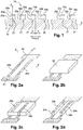
- a transducer comprising, on the substrate 10, an array of synchronous acoustic excitation sources, array comprising a first comb 20 and a second comb 30 each comprising a plurality of elementary transducers 21, 31; the elementary transducers of the first and second combs are interdigitated and arranged in the direction X of propagation of the guided volumetric waves; the elementary transducers each extend along the transverse axis Y; each elementary transducer 21, 31 comprises a lower electrode 22a, 32a conductive positioned on the substrate, a bar 24a, 34a of piezoelectric material positioned on the lower electrode and a top electrode 23a, 33a conductive positioned on the bar.
- the acoustic substrate plate of thickness e1 is made of electrically insulating material. Is then produced on the substrate 10 the network 19 of elementary transducers, network comprising a first comb 20 and a second comb 30 of elementary transducers 21, 31.
- a fifth step ( Fig. 4a ), the layer 40 of piezoelectric material is polarized; this polarization step is carried out for example by applying a same + V excitation potential on the conductors 41, 42 and the electrodes of the first and second series of upper electrodes, all the lower electrodes or the common lower electrode being connected to a mass of the power source producing + V potential (or vice versa).
- This polarization is particularly applicable to ferroelectric polar materials such as those mentioned above. It is then necessary, to force the local polarization of the material, to exceed the coercive field specific to the material in question by applying a potential difference between the upper and lower electrodes adequate.
- the coercivity field of congruent lithium lithium niobate and lithium tantalate is of the order of 21 kV / mm.
- the transducer obtained according to this second method comprises, as the previous one, an acoustic substrate plate 10 of electrically insulating material and a network of synchronous acoustic excitation sources; the network comprises a first comb 20 and a second comb 30 each comprising a plurality of elementary transducers 21, 31; the elementary transducers of the first and second combs are interdigitated and arranged in a direction (X) of propagation of the guided volume waves; the elementary transducers each extend along the transverse axis (Y).
- Each elementary transducer comprises a conductive lower electrode positioned on the substrate (or an electrode common to all the transducers), a bar made of piezoelectric material positioned on the lower electrode and a conductive upper electrode positioned on the bar.
- the lower electrode (s) can be supplied with a ground potential, and the upper electrodes of all the elementary transducers can be powered by the same power supply terminal (+ V) of the voltage source. (cf. Fig. 4d ), or the opposite.
- the alternating polarity of the bars of insulating material makes it possible to recover the electrical equivalent of an alternating power supply for the transducers.
Landscapes
- Physics & Mathematics (AREA)
- Acoustics & Sound (AREA)
- Surface Acoustic Wave Elements And Circuit Networks Thereof (AREA)
Claims (10)
- Wandler mit geführten Volumenwellen mit einer akustischen Substratplatte (10) aus elektrisch isolierendem Material und einer Anordnung synchroner akustischer Erregungsquellen, wobei die Anordnung einen ersten Kamm (20) und einen zweiten Kamm (30) umfasst, die jeweils mehrere Elementarwandler (21; 31) umfassen, wobei die Elementarwandler des ersten und des zweiten Kamms interdigital und in einer Ausbreitungsrichtung (X) der geführten Volumenwellen angeordnet sind, wobei sich die Elementarwandler jeweils entlang einer Querachse (Y) erstrecken, die senkrecht zur Ausbreitungsrichtung ist,
Wandler, dadurch gekennzeichnet, dass jeder Elementarwandler eine leitfähige untere Elektrode (22a, 22b, ..., 22c; 32a, 32b, ..., 32c) umfasst, die auf dem Substrat angeordnet ist, wobei die untere Elektrode eines Elementarwandlers von der unteren Elektrode der benachbarten Elementarwandler getrennt ist, ein Stab aus piezoelektrischem Material (24a, 24b, ..., 24c, 34a, 34b, ..., 34c), der auf der unteren Elektrode angeordnet ist, und eine leitfähige obere Elektrode (23a, 23b, ..., 23c; 33b, ..., 33c), die auf dem Stab angeordnet sind, wobei die obere Elektrode eines Elementarwandlers von der oberen Elektrode der benachbarten Elementarwandler getrennt ist. - Wandler nach Anspruch 1, bei dem eine Elektrode (22b oder 23b) eines Elementarwandlers elektrisch mit einem Stromversorgungsanschluss einer referenzierten elektrischen Erregungsquelle und die andere Elektrode (23b oder 22b) des gleichen Elementarwandlers mit einer elektrischen Masse dieser Quelle verbunden ist.
- Wandler nach einem der Ansprüche 1 bis 2, bei dem die untere Elektrode (32a; 22b) eines Elementarwandlers elektrisch mit der oberen Elektrode (23a; 33a) des vorhergehenden Elementarwandlers und mit der oberen Elektrode (23b; 33b) des nächsten Elementarwandlers verbunden ist und wobei die obere Elektrode (33a; 23b) eines Elementarwandlers elektrisch mit der unteren Elektrode (22a; 32a) des vorhergehenden Elementarwandlers und mit der unteren Elektrode (22b; 32b) des nächsten Elementarwandlers verbunden ist.
- Wandler nach Anspruch 1 bis 2, bei dem die unteren Elektroden (22a, 22b, ..., 22c; 32a, 32b, ..., 32c) aller Elementarwandler (21, 31) so angeordnet sind, dass sie zusammen mit einem ersten Anschluss einer Stromquelle verbunden sind, wobei die oberen Elektroden (23a, 23b, ..., 23c; 33a, 33b, ..., 33c) aller Elementarwandler (21, 31) so angeordnet sind, dass sie zusammen mit einem zweiten Anschluss der Stromquelle verbunden sind, wobei der erste Anschluss und der zweite Anschluss jeweils ein Potentialanschluss und eine Masse oder umgekehrt sind, und wobei der Stab (24a, 24b, ..., 24c) jedes Elementarwandlers (21) des ersten Kamms eine Polarisation aufweist , die der Polarisation des Stabes (34a, 34b, ..., 34c) jedes Elementarwandlers (31) des zweiten Kamms entgegengesetzt ist.
- Wandler nach Anspruch 4, bei dem das Substrat mit einer leitfähigen Schicht bedeckt ist, die eine gemeinsame Elektrode bildet, die elektrisch der Gesamtheit der unteren Elektroden aller Elementarwandler entspricht, wobei die polarisierten Stäben (24a, 34a, 24b, 34b, ..., 24c) 34c) auf der Leitschicht angeordnet sind, die die gemeinsame unteren Elektrode bildet.
- Verfahren zur Herstellung eines Wandlers nach einem der Ansprüche 1 bis 3, das die folgenden Schritte umfasst:• Herstellen einer akustischen Substratplatte (10) aus elektrisch isolierendem Material,• Aufbringen auf dem Substrat einer ersten Reihe (22) von unteren Elektroden (22a, 22b, ..., 22c) und einer zweiten Reihe (32) von unteren Elektroden (32a, 32b, ..., 32c) aus elektrisch leitfähigem Material, die interdigital und in einer Ausbreitungsrichtung (X) der geführten Volumenwellen angeordnet sind, wobei sich jede untere Elektrode (22a, 32a, 22b, 32b, ..., 22c, 32c) entlang einer Querachse (Y) erstreckt, die senkrecht zur Ausbreitungsrichtung (X) ist, wobei die Elektroden (22a, 22b, ..., 22c) der ersten Reihe von unteren Elektroden elektrisch miteinander verbunden sind und die Elektroden (32a, 32b, ..., 32c) der zweiten Reihe von unteren Elektroden elektrisch miteinander verbunden sind,• Bedecken der ersten Reihe von unteren Elektroden und der zweiten Reihe von unteren Elektroden mit einer Schicht (40) aus einem piezoelektrischen Material,• Aufbringen auf dem piezoelektrischen Material einer ersten Reihe (23) von oberen Elektroden (23a, 23b, ..., 23c) und einer zweiten Reihe (33) von oberen Elektroden (33a, 33b, ..., 33c) aus elektrisch leitfähigem Material, die interdigital und in Ausbreitungsrichtung (X) angeordnet sind, wobei sich jede obere Elektrode (23a, 33a, 23b, 33b, ..., 23c, 33c) entlang der Querachse (Y) erstreckt, wobei die Elektroden (23a, 23b), ..., 23c) der ersten Reihe von oberen Elektroden elektrisch miteinander und mit den Elektroden (32a, 32b, ..., 32c) der zweiten Reihe von unteren Elektroden verbunden sind und die Elektroden (33a, 33b, ..., 33c) der zweiten Reihe von oberen Elektroden elektrisch miteinander und mit den Elektroden (22a, 22b, ..., 22c) der ersten Reihe von unteren Elektroden verbunden sind,• Ätzen der Schicht aus piezoelektrischem Material durch Entfernen des piezoelektrischen Materials zwischen den oberen Elektroden, um einen Stab aus piezoelektrischem Material unter jeder oberen Elektrode zu bilden.
- Verfahren zur Herstellung eines Wandlers nach einem der Ansprüche 1, 2 oder 5, wobei das Verfahren die folgenden Schritte umfasst:• Herstellen einer akustischen Substratplatte (10) aus elektrisch isolierendem Material,• entweder Aufbringen einer ersten Reihe (22) von unteren Elektroden (22a, 22b, ..., 22c) und einer zweiten Reihe (32) von unteren Elektroden (32a, 32b, ..., 32c) aus elektrisch leitfähigem Material auf dem Substrat, wobei sich jede untere Elektrode (22a, 32a, 22b, 32b, ..., 22c, 32c) entlang einer Querachse (Y) erstreckt, wobei die Elektroden der ersten Reihe und der zweiten Reihe von unteren Elektroden interdigital und in einer Ausbreitungsrichtung (X) der geführten Volumenwellen angeordnet sind, die senkrecht zu einer Querachse (Y) verläuft, wobei die Elektroden (22a, 22b, ..., 22c) der ersten Reihe von unteren Elektroden und die Elektroden (32a, 32b, ..., 32c) der zweiten Reihe von unteren Elektroden elektrisch miteinander verbunden sind oder Aufbringen einer Schicht (43) aus elektrisch leitfähigem Material, die eine gemeinsame untere Elektrode bildet,• Bedecken der unteren Elektrode oder der unteren Elektroden (43; 22a, 32a, 22b, 32b, ..., 22c, 32c) mit einer Schicht (40) aus einem piezoelektrischen Material,• Aufbringen auf einer Schicht (40) aus piezoelektrischem Material einer ersten Reihe (23) von oberen Elektroden (23a, 23b, ..., 23c) und einer zweiten Reihe (33) von oberen Elektroden (33a, 33b, 33c) aus elektrisch leitfähigem Material, welche interdigital und in Ausbreitungsrichtung angeordnet sind, wobei sich jede Elektrode der ersten Reihe und der zweiten Reihe von oberen Elektroden entlang der Querachse erstrecken, wobei die Elektroden der ersten Reihe von oberen Elektroden elektrisch miteinander verbunden sind und die Elektroden der zweiten Reihe von oberen Elektroden elektrisch miteinander verbunden sind.• Polarisieren der Schicht aus piezoelektrischem Material (40)• Ätzen der Schicht aus piezoelektrischem Material durch Entfernen des piezoelektrischen Materials zwischen den oberen Elektroden, um einen Stab (24a, 34a, 24b, 34b, ..., 24c, 34c) aus piezoelektrischem Material unter jeder oberen Elektrode zu bilden,• Umpolarisieren der Stäbe (24a, 24b, ..., 24c) aus piezoelektrischem Material, die unter den Elektroden der ersten Reihe von oberen Elektroden angeordnet sind.
- Wandler nach einem der Ansprüche 1 bis 5, bei dem das piezoelektrische Material ferroelektrische Eigenschaften aufweist.
- Vorrichtung mit einem Wandler nach einem der Ansprüche 1 bis 5 oder 8, die mit einer Hochfrequenzantenne verbunden ist, die dazu eingerichtet ist, elastische Wellen anzuregen und / oder zu detektieren, die von dem drahtlosen Wandler gesendet und / oder empfangen werden.
- Differenzialer Eingangs- / Ausgangsfrequenzfilter mit einem Wandler nach einem der Ansprüche 1 bis 5, 8 oder 9.
Applications Claiming Priority (1)
| Application Number | Priority Date | Filing Date | Title |
|---|---|---|---|
| FR1563360A FR3046090B1 (fr) | 2015-12-28 | 2015-12-28 | Perfectionnement aux transducteurs a ondes de volume guidees en surface |
Publications (2)
| Publication Number | Publication Date |
|---|---|
| EP3188367A1 EP3188367A1 (de) | 2017-07-05 |
| EP3188367B1 true EP3188367B1 (de) | 2019-06-19 |
Family
ID=55752459
Family Applications (1)
| Application Number | Title | Priority Date | Filing Date |
|---|---|---|---|
| EP16020513.4A Active EP3188367B1 (de) | 2015-12-28 | 2016-12-23 | Verbesserung von wandlern mit an der oberfläche geführten volumenwellen |
Country Status (2)
| Country | Link |
|---|---|
| EP (1) | EP3188367B1 (de) |
| FR (1) | FR3046090B1 (de) |
Cited By (1)
| Publication number | Priority date | Publication date | Assignee | Title |
|---|---|---|---|---|
| WO2025141201A1 (fr) * | 2023-12-31 | 2025-07-03 | Soitec | Dispositif à ondes élastiques |
Families Citing this family (1)
| Publication number | Priority date | Publication date | Assignee | Title |
|---|---|---|---|---|
| WO2024012653A1 (en) * | 2022-07-11 | 2024-01-18 | Silicon Austria Labs Gmbh | Resonator filter and method operating a resonator filter |
Family Cites Families (5)
| Publication number | Priority date | Publication date | Assignee | Title |
|---|---|---|---|---|
| US7639105B2 (en) * | 2007-01-19 | 2009-12-29 | Georgia Tech Research Corporation | Lithographically-defined multi-standard multi-frequency high-Q tunable micromechanical resonators |
| US7898158B1 (en) * | 2007-11-01 | 2011-03-01 | Rf Micro Devices, Inc. | MEMS vibrating structure using a single-crystal piezoelectric thin-film layer having domain inversions |
| JP5848131B2 (ja) * | 2008-12-17 | 2016-01-27 | アナログ デバイシス, インコーポレイテッド | 機械共振構造体を備える機器 |
| US8525619B1 (en) * | 2010-05-28 | 2013-09-03 | Sandia Corporation | Lateral acoustic wave resonator comprising a suspended membrane of low damping resonator material |
| FR2997027B1 (fr) * | 2012-10-19 | 2015-01-02 | Centre Nat Rech Scient | Transducteur a ondes de volume guidees en suface par des structures d'excitation synchrone |
-
2015
- 2015-12-28 FR FR1563360A patent/FR3046090B1/fr active Active
-
2016
- 2016-12-23 EP EP16020513.4A patent/EP3188367B1/de active Active
Non-Patent Citations (1)
| Title |
|---|
| None * |
Cited By (2)
| Publication number | Priority date | Publication date | Assignee | Title |
|---|---|---|---|---|
| WO2025141201A1 (fr) * | 2023-12-31 | 2025-07-03 | Soitec | Dispositif à ondes élastiques |
| FR3157992A1 (fr) * | 2023-12-31 | 2025-07-04 | Soitec | Dispositif à ondes élastiques |
Also Published As
| Publication number | Publication date |
|---|---|
| FR3046090A1 (fr) | 2017-06-30 |
| FR3046090B1 (fr) | 2021-06-25 |
| EP3188367A1 (de) | 2017-07-05 |
Similar Documents
| Publication | Publication Date | Title |
|---|---|---|
| EP2909932B1 (de) | Wandler mit durch synchrone anregungsstrukturen geführten volumenwellen | |
| CN112840561B (zh) | 谐振腔表面声波(saw)滤波器 | |
| US10374573B2 (en) | Plate wave devices with wave confinement structures and fabrication methods | |
| EP1748556B1 (de) | Hybridresonanzstruktur | |
| JP2018506930A5 (de) | ||
| EP1222735B1 (de) | Akustisches grenzflächenwellenfilter insbesondere für drahtlose übertragungssysteme | |
| EP2351214B1 (de) | Transversal gekoppelte filterelemente auf volumenwellenresonanzstrukturen mit mehrfachen harmonischen resonanzen | |
| EP4409743B1 (de) | Oberflächenwellenfilter mit abschnitten stehender wellen | |
| EP2385625A1 (de) | Kombinierer mit akustischem Wandler | |
| EP1299945A1 (de) | Akustische oberflächenwellenanordnung mit alternierenden polarisationsgebieten | |
| EP3188367B1 (de) | Verbesserung von wandlern mit an der oberfläche geführten volumenwellen | |
| EP3034183B1 (de) | Akustische vorrichtung zur galvanischen isolierung | |
| EP0369835B1 (de) | Wandler für ein akustisches Oberflächenwellen-Filter | |
| EP0982859A1 (de) | Akustisches Filter mit zwei verschiedene Kanälen und Sperrkompensation | |
| WO2010031924A1 (fr) | Dispositif a ondes acoustiques d'interfaces | |
| FR2965991A1 (fr) | Dispositif acoustique d'isolation galvanique | |
| WO2025141199A1 (fr) | Dispositif à ondes élastiques | |
| WO2025141201A1 (fr) | Dispositif à ondes élastiques | |
| WO2025141196A2 (fr) | Dispositif à ondes élastiques | |
| CH710638A2 (fr) | Un filtre-transformateur piézoélectrique à ondes élastiques de volume. | |
| WO2025141195A1 (fr) | Dispositif à ondes élastiques | |
| WO2025141190A1 (fr) | Dispositif à ondes élastiques avec électrodes en peigne interdigitées partiellement enterrées | |
| WO2025141194A1 (fr) | Dispositif à ondes élastiques | |
| FR3153708A1 (fr) | Dispositif à ondes élastiques |
Legal Events
| Date | Code | Title | Description |
|---|---|---|---|
| PUAI | Public reference made under article 153(3) epc to a published international application that has entered the european phase |
Free format text: ORIGINAL CODE: 0009012 |
|
| STAA | Information on the status of an ep patent application or granted ep patent |
Free format text: STATUS: THE APPLICATION HAS BEEN PUBLISHED |
|
| AK | Designated contracting states |
Kind code of ref document: A1 Designated state(s): AL AT BE BG CH CY CZ DE DK EE ES FI FR GB GR HR HU IE IS IT LI LT LU LV MC MK MT NL NO PL PT RO RS SE SI SK SM TR |
|
| AX | Request for extension of the european patent |
Extension state: BA ME |
|
| STAA | Information on the status of an ep patent application or granted ep patent |
Free format text: STATUS: REQUEST FOR EXAMINATION WAS MADE |
|
| 17P | Request for examination filed |
Effective date: 20171220 |
|
| RBV | Designated contracting states (corrected) |
Designated state(s): AL AT BE BG CH CY CZ DE DK EE ES FI FR GB GR HR HU IE IS IT LI LT LU LV MC MK MT NL NO PL PT RO RS SE SI SK SM TR |
|
| GRAP | Despatch of communication of intention to grant a patent |
Free format text: ORIGINAL CODE: EPIDOSNIGR1 |
|
| STAA | Information on the status of an ep patent application or granted ep patent |
Free format text: STATUS: GRANT OF PATENT IS INTENDED |
|
| INTG | Intention to grant announced |
Effective date: 20180807 |
|
| GRAJ | Information related to disapproval of communication of intention to grant by the applicant or resumption of examination proceedings by the epo deleted |
Free format text: ORIGINAL CODE: EPIDOSDIGR1 |
|
| STAA | Information on the status of an ep patent application or granted ep patent |
Free format text: STATUS: REQUEST FOR EXAMINATION WAS MADE |
|
| INTC | Intention to grant announced (deleted) | ||
| GRAP | Despatch of communication of intention to grant a patent |
Free format text: ORIGINAL CODE: EPIDOSNIGR1 |
|
| STAA | Information on the status of an ep patent application or granted ep patent |
Free format text: STATUS: GRANT OF PATENT IS INTENDED |
|
| INTG | Intention to grant announced |
Effective date: 20190111 |
|
| GRAS | Grant fee paid |
Free format text: ORIGINAL CODE: EPIDOSNIGR3 |
|
| GRAA | (expected) grant |
Free format text: ORIGINAL CODE: 0009210 |
|
| STAA | Information on the status of an ep patent application or granted ep patent |
Free format text: STATUS: THE PATENT HAS BEEN GRANTED |
|
| AK | Designated contracting states |
Kind code of ref document: B1 Designated state(s): AL AT BE BG CH CY CZ DE DK EE ES FI FR GB GR HR HU IE IS IT LI LT LU LV MC MK MT NL NO PL PT RO RS SE SI SK SM TR |
|
| REG | Reference to a national code |
Ref country code: GB Ref legal event code: FG4D Free format text: NOT ENGLISH |
|
| REG | Reference to a national code |
Ref country code: CH Ref legal event code: EP |
|
| REG | Reference to a national code |
Ref country code: IE Ref legal event code: FG4D Free format text: LANGUAGE OF EP DOCUMENT: FRENCH |
|
| REG | Reference to a national code |
Ref country code: DE Ref legal event code: R096 Ref document number: 602016015358 Country of ref document: DE |
|
| REG | Reference to a national code |
Ref country code: AT Ref legal event code: REF Ref document number: 1146776 Country of ref document: AT Kind code of ref document: T Effective date: 20190715 |
|
| REG | Reference to a national code |
Ref country code: SE Ref legal event code: TRGR |
|
| REG | Reference to a national code |
Ref country code: CH Ref legal event code: NV Representative=s name: BOVARD AG PATENT- UND MARKENANWAELTE, CH |
|
| REG | Reference to a national code |
Ref country code: NL Ref legal event code: MP Effective date: 20190619 |
|
| PG25 | Lapsed in a contracting state [announced via postgrant information from national office to epo] |
Ref country code: NO Free format text: LAPSE BECAUSE OF FAILURE TO SUBMIT A TRANSLATION OF THE DESCRIPTION OR TO PAY THE FEE WITHIN THE PRESCRIBED TIME-LIMIT Effective date: 20190919 Ref country code: AL Free format text: LAPSE BECAUSE OF FAILURE TO SUBMIT A TRANSLATION OF THE DESCRIPTION OR TO PAY THE FEE WITHIN THE PRESCRIBED TIME-LIMIT Effective date: 20190619 Ref country code: LT Free format text: LAPSE BECAUSE OF FAILURE TO SUBMIT A TRANSLATION OF THE DESCRIPTION OR TO PAY THE FEE WITHIN THE PRESCRIBED TIME-LIMIT Effective date: 20190619 Ref country code: HR Free format text: LAPSE BECAUSE OF FAILURE TO SUBMIT A TRANSLATION OF THE DESCRIPTION OR TO PAY THE FEE WITHIN THE PRESCRIBED TIME-LIMIT Effective date: 20190619 |
|
| REG | Reference to a national code |
Ref country code: LT Ref legal event code: MG4D |
|
| PG25 | Lapsed in a contracting state [announced via postgrant information from national office to epo] |
Ref country code: GR Free format text: LAPSE BECAUSE OF FAILURE TO SUBMIT A TRANSLATION OF THE DESCRIPTION OR TO PAY THE FEE WITHIN THE PRESCRIBED TIME-LIMIT Effective date: 20190920 Ref country code: RS Free format text: LAPSE BECAUSE OF FAILURE TO SUBMIT A TRANSLATION OF THE DESCRIPTION OR TO PAY THE FEE WITHIN THE PRESCRIBED TIME-LIMIT Effective date: 20190619 Ref country code: BG Free format text: LAPSE BECAUSE OF FAILURE TO SUBMIT A TRANSLATION OF THE DESCRIPTION OR TO PAY THE FEE WITHIN THE PRESCRIBED TIME-LIMIT Effective date: 20190919 Ref country code: LV Free format text: LAPSE BECAUSE OF FAILURE TO SUBMIT A TRANSLATION OF THE DESCRIPTION OR TO PAY THE FEE WITHIN THE PRESCRIBED TIME-LIMIT Effective date: 20190619 |
|
| PG25 | Lapsed in a contracting state [announced via postgrant information from national office to epo] |
Ref country code: RO Free format text: LAPSE BECAUSE OF FAILURE TO SUBMIT A TRANSLATION OF THE DESCRIPTION OR TO PAY THE FEE WITHIN THE PRESCRIBED TIME-LIMIT Effective date: 20190619 Ref country code: SK Free format text: LAPSE BECAUSE OF FAILURE TO SUBMIT A TRANSLATION OF THE DESCRIPTION OR TO PAY THE FEE WITHIN THE PRESCRIBED TIME-LIMIT Effective date: 20190619 Ref country code: CZ Free format text: LAPSE BECAUSE OF FAILURE TO SUBMIT A TRANSLATION OF THE DESCRIPTION OR TO PAY THE FEE WITHIN THE PRESCRIBED TIME-LIMIT Effective date: 20190619 Ref country code: EE Free format text: LAPSE BECAUSE OF FAILURE TO SUBMIT A TRANSLATION OF THE DESCRIPTION OR TO PAY THE FEE WITHIN THE PRESCRIBED TIME-LIMIT Effective date: 20190619 Ref country code: PT Free format text: LAPSE BECAUSE OF FAILURE TO SUBMIT A TRANSLATION OF THE DESCRIPTION OR TO PAY THE FEE WITHIN THE PRESCRIBED TIME-LIMIT Effective date: 20191021 Ref country code: NL Free format text: LAPSE BECAUSE OF FAILURE TO SUBMIT A TRANSLATION OF THE DESCRIPTION OR TO PAY THE FEE WITHIN THE PRESCRIBED TIME-LIMIT Effective date: 20190619 |
|
| PG25 | Lapsed in a contracting state [announced via postgrant information from national office to epo] |
Ref country code: IT Free format text: LAPSE BECAUSE OF FAILURE TO SUBMIT A TRANSLATION OF THE DESCRIPTION OR TO PAY THE FEE WITHIN THE PRESCRIBED TIME-LIMIT Effective date: 20190619 Ref country code: SM Free format text: LAPSE BECAUSE OF FAILURE TO SUBMIT A TRANSLATION OF THE DESCRIPTION OR TO PAY THE FEE WITHIN THE PRESCRIBED TIME-LIMIT Effective date: 20190619 Ref country code: IS Free format text: LAPSE BECAUSE OF FAILURE TO SUBMIT A TRANSLATION OF THE DESCRIPTION OR TO PAY THE FEE WITHIN THE PRESCRIBED TIME-LIMIT Effective date: 20191019 Ref country code: ES Free format text: LAPSE BECAUSE OF FAILURE TO SUBMIT A TRANSLATION OF THE DESCRIPTION OR TO PAY THE FEE WITHIN THE PRESCRIBED TIME-LIMIT Effective date: 20190619 |
|
| PG25 | Lapsed in a contracting state [announced via postgrant information from national office to epo] |
Ref country code: TR Free format text: LAPSE BECAUSE OF FAILURE TO SUBMIT A TRANSLATION OF THE DESCRIPTION OR TO PAY THE FEE WITHIN THE PRESCRIBED TIME-LIMIT Effective date: 20190619 |
|
| PG25 | Lapsed in a contracting state [announced via postgrant information from national office to epo] |
Ref country code: PL Free format text: LAPSE BECAUSE OF FAILURE TO SUBMIT A TRANSLATION OF THE DESCRIPTION OR TO PAY THE FEE WITHIN THE PRESCRIBED TIME-LIMIT Effective date: 20190619 Ref country code: DK Free format text: LAPSE BECAUSE OF FAILURE TO SUBMIT A TRANSLATION OF THE DESCRIPTION OR TO PAY THE FEE WITHIN THE PRESCRIBED TIME-LIMIT Effective date: 20190619 |
|
| PG25 | Lapsed in a contracting state [announced via postgrant information from national office to epo] |
Ref country code: IS Free format text: LAPSE BECAUSE OF FAILURE TO SUBMIT A TRANSLATION OF THE DESCRIPTION OR TO PAY THE FEE WITHIN THE PRESCRIBED TIME-LIMIT Effective date: 20200224 |
|
| REG | Reference to a national code |
Ref country code: DE Ref legal event code: R097 Ref document number: 602016015358 Country of ref document: DE |
|
| PLBE | No opposition filed within time limit |
Free format text: ORIGINAL CODE: 0009261 |
|
| STAA | Information on the status of an ep patent application or granted ep patent |
Free format text: STATUS: NO OPPOSITION FILED WITHIN TIME LIMIT |
|
| PG2D | Information on lapse in contracting state deleted |
Ref country code: IS |
|
| 26N | No opposition filed |
Effective date: 20200603 |
|
| PG25 | Lapsed in a contracting state [announced via postgrant information from national office to epo] |
Ref country code: SI Free format text: LAPSE BECAUSE OF FAILURE TO SUBMIT A TRANSLATION OF THE DESCRIPTION OR TO PAY THE FEE WITHIN THE PRESCRIBED TIME-LIMIT Effective date: 20190619 Ref country code: MC Free format text: LAPSE BECAUSE OF FAILURE TO SUBMIT A TRANSLATION OF THE DESCRIPTION OR TO PAY THE FEE WITHIN THE PRESCRIBED TIME-LIMIT Effective date: 20190619 |
|
| PG25 | Lapsed in a contracting state [announced via postgrant information from national office to epo] |
Ref country code: IE Free format text: LAPSE BECAUSE OF NON-PAYMENT OF DUE FEES Effective date: 20191223 Ref country code: LU Free format text: LAPSE BECAUSE OF NON-PAYMENT OF DUE FEES Effective date: 20191223 |
|
| REG | Reference to a national code |
Ref country code: AT Ref legal event code: UEP Ref document number: 1146776 Country of ref document: AT Kind code of ref document: T Effective date: 20190619 |
|
| PG25 | Lapsed in a contracting state [announced via postgrant information from national office to epo] |
Ref country code: CY Free format text: LAPSE BECAUSE OF FAILURE TO SUBMIT A TRANSLATION OF THE DESCRIPTION OR TO PAY THE FEE WITHIN THE PRESCRIBED TIME-LIMIT Effective date: 20190619 |
|
| PG25 | Lapsed in a contracting state [announced via postgrant information from national office to epo] |
Ref country code: HU Free format text: LAPSE BECAUSE OF FAILURE TO SUBMIT A TRANSLATION OF THE DESCRIPTION OR TO PAY THE FEE WITHIN THE PRESCRIBED TIME-LIMIT; INVALID AB INITIO Effective date: 20161223 Ref country code: MT Free format text: LAPSE BECAUSE OF FAILURE TO SUBMIT A TRANSLATION OF THE DESCRIPTION OR TO PAY THE FEE WITHIN THE PRESCRIBED TIME-LIMIT Effective date: 20190619 |
|
| PGFP | Annual fee paid to national office [announced via postgrant information from national office to epo] |
Ref country code: SE Payment date: 20211110 Year of fee payment: 6 Ref country code: AT Payment date: 20211129 Year of fee payment: 6 Ref country code: FI Payment date: 20211209 Year of fee payment: 6 |
|
| PGFP | Annual fee paid to national office [announced via postgrant information from national office to epo] |
Ref country code: CH Payment date: 20211116 Year of fee payment: 6 Ref country code: BE Payment date: 20211119 Year of fee payment: 6 |
|
| PG25 | Lapsed in a contracting state [announced via postgrant information from national office to epo] |
Ref country code: MK Free format text: LAPSE BECAUSE OF FAILURE TO SUBMIT A TRANSLATION OF THE DESCRIPTION OR TO PAY THE FEE WITHIN THE PRESCRIBED TIME-LIMIT Effective date: 20190619 |
|
| REG | Reference to a national code |
Ref country code: DE Ref legal event code: R081 Ref document number: 602016015358 Country of ref document: DE Owner name: SOITEC, FR Free format text: FORMER OWNERS: CNRS CENTRE NATIONAL DE LA RECHERCHE SCIENTIFIQUE, PARIS, FR; FREC|N|SYS, BESANCON, FR Ref country code: DE Ref legal event code: R081 Ref document number: 602016015358 Country of ref document: DE Owner name: CNRS CENTRE NATIONAL DE LA RECHERCHE SCIENTIFI, FR Free format text: FORMER OWNERS: CNRS CENTRE NATIONAL DE LA RECHERCHE SCIENTIFIQUE, PARIS, FR; FREC|N|SYS, BESANCON, FR |
|
| REG | Reference to a national code |
Ref country code: GB Ref legal event code: 732E Free format text: REGISTERED BETWEEN 20230622 AND 20230628 |
|
| REG | Reference to a national code |
Ref country code: CH Ref legal event code: PL |
|
| REG | Reference to a national code |
Ref country code: SE Ref legal event code: EUG |
|
| REG | Reference to a national code |
Ref country code: AT Ref legal event code: MM01 Ref document number: 1146776 Country of ref document: AT Kind code of ref document: T Effective date: 20221223 |
|
| REG | Reference to a national code |
Ref country code: BE Ref legal event code: MM Effective date: 20221231 |
|
| PG25 | Lapsed in a contracting state [announced via postgrant information from national office to epo] |
Ref country code: SE Free format text: LAPSE BECAUSE OF NON-PAYMENT OF DUE FEES Effective date: 20221224 Ref country code: LI Free format text: LAPSE BECAUSE OF NON-PAYMENT OF DUE FEES Effective date: 20221231 Ref country code: CH Free format text: LAPSE BECAUSE OF NON-PAYMENT OF DUE FEES Effective date: 20221231 Ref country code: AT Free format text: LAPSE BECAUSE OF NON-PAYMENT OF DUE FEES Effective date: 20221223 |
|
| PG25 | Lapsed in a contracting state [announced via postgrant information from national office to epo] |
Ref country code: BE Free format text: LAPSE BECAUSE OF NON-PAYMENT OF DUE FEES Effective date: 20221231 |
|
| PG25 | Lapsed in a contracting state [announced via postgrant information from national office to epo] |
Ref country code: FI Free format text: LAPSE BECAUSE OF NON-PAYMENT OF DUE FEES Effective date: 20221223 |
|
| PGFP | Annual fee paid to national office [announced via postgrant information from national office to epo] |
Ref country code: DE Payment date: 20251104 Year of fee payment: 10 |
|
| PGFP | Annual fee paid to national office [announced via postgrant information from national office to epo] |
Ref country code: GB Payment date: 20251114 Year of fee payment: 10 |
|
| PGFP | Annual fee paid to national office [announced via postgrant information from national office to epo] |
Ref country code: FR Payment date: 20251124 Year of fee payment: 10 |