EP3188338A1 - Grid-connected control method based on virtual synchronizer and device thereof - Google Patents
Grid-connected control method based on virtual synchronizer and device thereof Download PDFInfo
- Publication number
- EP3188338A1 EP3188338A1 EP16177178.7A EP16177178A EP3188338A1 EP 3188338 A1 EP3188338 A1 EP 3188338A1 EP 16177178 A EP16177178 A EP 16177178A EP 3188338 A1 EP3188338 A1 EP 3188338A1
- Authority
- EP
- European Patent Office
- Prior art keywords
- inverter
- grid
- frequency
- voltage
- deviation
- Prior art date
- Legal status (The legal status is an assumption and is not a legal conclusion. Google has not performed a legal analysis and makes no representation as to the accuracy of the status listed.)
- Granted
Links
Images



Classifications
-
- H—ELECTRICITY
- H02—GENERATION; CONVERSION OR DISTRIBUTION OF ELECTRIC POWER
- H02J—ELECTRIC POWER NETWORKS; CIRCUIT ARRANGEMENTS OR SYSTEMS FOR SUPPLYING OR DISTRIBUTING ELECTRIC POWER; SYSTEMS FOR STORING ELECTRIC ENERGY
- H02J3/00—Circuit arrangements for AC mains or AC distribution networks
- H02J3/38—Arrangements for feeding a single network from two or more generators or sources in parallel; Arrangements for feeding already energised networks from additional generators or sources in parallel
- H02J3/40—Synchronisation of generators for connection to a network or to another generator
-
- H—ELECTRICITY
- H02—GENERATION; CONVERSION OR DISTRIBUTION OF ELECTRIC POWER
- H02J—ELECTRIC POWER NETWORKS; CIRCUIT ARRANGEMENTS OR SYSTEMS FOR SUPPLYING OR DISTRIBUTING ELECTRIC POWER; SYSTEMS FOR STORING ELECTRIC ENERGY
- H02J3/00—Circuit arrangements for AC mains or AC distribution networks
- H02J3/38—Arrangements for feeding a single network from two or more generators or sources in parallel; Arrangements for feeding already energised networks from additional generators or sources in parallel
-
- H—ELECTRICITY
- H02—GENERATION; CONVERSION OR DISTRIBUTION OF ELECTRIC POWER
- H02J—ELECTRIC POWER NETWORKS; CIRCUIT ARRANGEMENTS OR SYSTEMS FOR SUPPLYING OR DISTRIBUTING ELECTRIC POWER; SYSTEMS FOR STORING ELECTRIC ENERGY
- H02J3/00—Circuit arrangements for AC mains or AC distribution networks
- H02J3/38—Arrangements for feeding a single network from two or more generators or sources in parallel; Arrangements for feeding already energised networks from additional generators or sources in parallel
- H02J3/40—Synchronisation of generators for connection to a network or to another generator
- H02J3/42—Synchronisation of generators for connection to a network or to another generator with automatic parallel connection when synchronisation is achieved
-
- H—ELECTRICITY
- H02—GENERATION; CONVERSION OR DISTRIBUTION OF ELECTRIC POWER
- H02J—ELECTRIC POWER NETWORKS; CIRCUIT ARRANGEMENTS OR SYSTEMS FOR SUPPLYING OR DISTRIBUTING ELECTRIC POWER; SYSTEMS FOR STORING ELECTRIC ENERGY
- H02J3/00—Circuit arrangements for AC mains or AC distribution networks
- H02J3/001—Arrangements for handling faults or abnormalities, e.g. emergencies or contingencies
- H02J3/0014—Arrangements for handling faults or abnormalities, e.g. emergencies or contingencies for preventing or reducing power oscillations in networks
-
- H—ELECTRICITY
- H02—GENERATION; CONVERSION OR DISTRIBUTION OF ELECTRIC POWER
- H02J—ELECTRIC POWER NETWORKS; CIRCUIT ARRANGEMENTS OR SYSTEMS FOR SUPPLYING OR DISTRIBUTING ELECTRIC POWER; SYSTEMS FOR STORING ELECTRIC ENERGY
- H02J7/00—Circuit arrangements for charging or discharging batteries or for supplying loads from batteries
- H02J7/865—Battery or charger load switching, e.g. concurrent charging and load supply
-
- Y—GENERAL TAGGING OF NEW TECHNOLOGICAL DEVELOPMENTS; GENERAL TAGGING OF CROSS-SECTIONAL TECHNOLOGIES SPANNING OVER SEVERAL SECTIONS OF THE IPC; TECHNICAL SUBJECTS COVERED BY FORMER USPC CROSS-REFERENCE ART COLLECTIONS [XRACs] AND DIGESTS
- Y02—TECHNOLOGIES OR APPLICATIONS FOR MITIGATION OR ADAPTATION AGAINST CLIMATE CHANGE
- Y02P—CLIMATE CHANGE MITIGATION TECHNOLOGIES IN THE PRODUCTION OR PROCESSING OF GOODS
- Y02P80/00—Climate change mitigation technologies for sector-wide applications
- Y02P80/10—Efficient use of energy, e.g. using compressed air or pressurized fluid as energy carrier
- Y02P80/14—District level solutions, i.e. local energy networks
Definitions
- the present disclosure relates to the field of inverter control technology, and particularly to a grid-connected control method based on a virtual synchronizer and a device thereof.
- Control on a virtual synchronizer has an advantage of droop control, and can realize droop adjustment control between a frequency and an active power and between a voltage and a reactive power. Also, the virtual synchronizer, which has an inertial component, can perform smooth adjustment on the frequency. An energy-storage inverter based on control of the virtual synchronizer has been widely adopted in an actual application.
- the energy-storage inverter based on the control of the virtual synchronizer performs grid-connected operation, it is determined whether an alternating-current voltage outputted from the energy-storage inverter is synchronous with a voltage of an external grid. Only in a case of a positive determination, the energy-storage inverter can be connected to the grid with reduced impact to the grid in a grid-connected process.
- a grid-connected control method based on a virtual synchronizer and a device thereof are provided according to the present disclosure, for successfully and smoothly connecting an energy-storage inverter to the grid without any impact to the grid.
- a grid-connected control method based on a virtual synchronizer is provided according to an embodiment of the present disclosure.
- the grid-connected control method includes:
- the adjusting the set output voltage of the inverter in a case that it is detected that the first deviation exceeds the first set voltage threshold may include:
- the adjusting the set output frequency of the inverter in a case that it is detected that the second deviation exceeds the first set frequency threshold may include:
- the grid-connected control method may further include:
- the grid-connected control method may further include:
- a grid-connected control device based on a virtual synchronizer is further provided according to an embodiment of the present disclosure.
- the grid-connected control device includes a first deviation determination unit, a set output voltage adjustment unit, a second deviation determination unit, a set output frequency adjustment unit and a control unit.
- the first deviation determination unit may be configured to detect whether a first deviation between an output voltage of the inverter and a voltage of a grid exceeds a first set voltage threshold.
- the set output voltage adjustment unit is configured to adjust the set output voltage of an inverter in a case that the first deviation exceeds the first set voltage threshold, so that the first deviation falls within the first set voltage threshold.
- the second deviation determination unit may be configured to determine whether a second deviation between an output frequency of the inverter and a frequency of a grid exceeds a first set frequency threshold.
- the set output frequency adjustment unit is configured to adjust a set output frequency of the inverter in a case that the second deviation exceeds the first set frequency threshold, so that the second deviation falls within the first set frequency threshold.
- the control unit may be configured to control the inverter to connect to the grid when a phase of a voltage of the grid is consistent with a phase of an output voltage of the inverter in a case that the first deviation falls within the first set voltage threshold and the second deviation falls within the first set frequency threshold.
- the first deviation determination unit may include a first deviation determination subunit.
- the set output voltage adjustment unit may include a set output voltage decrease adjustment subunit and a set output voltage increase adjustment subunit.
- the first deviation determination subunit may be configured to determine whether the output voltage of the inverter is greater than the voltage of the grid in a case that the first deviation between the output voltage of the inverter and the voltage of the grid exceeds the first set voltage threshold.
- the set output voltage decrease adjustment subunit may be configured to decrease the set output voltage of the inverter with a preset first step size in a case that the output voltage of the inverter is greater than the voltage of the grid.
- the set output voltage increase adjustment subunit may be configured to increase the set output voltage of the inverter with a preset second step size in a case that the output voltage of the inverter is less than the voltage of the grid.
- the second deviation determination unit may include a second deviation determination subunit.
- the set output frequency adjustment unit may include a set output frequency decrease adjustment subunit and a set output frequency increase adjustment subunit.
- the second deviation determination subunit may be configured to determine whether the output frequency of the inverter is greater than the frequency of the grid in a case that the second deviation between the output frequency of the inverter and the frequency of the grid exceeds the first set frequency threshold.
- the set output frequency decrease adjustment subunit may be configured to decrease the set output frequency of the inverter with a preset third step size in a case that the output frequency of the inverter is greater than the frequency of the grid.
- the set output frequency increase adjustment subunit may be configured to increase the set output frequency of the inverter with a preset fourth step size in a case that the output frequency of the inverter is less than the frequency of the grid.
- the grid-connected control device may further include a voltage recovery increase unit and a voltage recovery decrease unit.
- the voltage recovery increase unit may be configured to increase the set output voltage with a fifth step size after the inverter is connected to the grid successfully in a case that the set output voltage is decreased with the preset first step size before the inverter is connected to the grid, until a third deviation between the set output voltage of the inverter and the voltage of the grid falls within a second set voltage threshold, and set the set output voltage of the inverter to be the voltage of the grid.
- the voltage recovery decrease unit may be configured to decrease the set output voltage with a sixth step size after the inverter is connected to the grid successfully in a case that the set output voltage is increased with the preset second step size before the inverter is connected to the grid, until a third deviation between the set output voltage of the inverter and the voltage of the grid falls within a second set voltage threshold, and set the set output voltage of the inverter to be the voltage of the grid.
- the grid-connected control device may further include a frequency recovery increase unit and a frequency recovery decrease unit.
- the frequency recovery increase unit may be configured to increase the set output frequency of the inverter with a seventh step size after the inverter is connected to the grid successfully in a case that the set output frequency of the inverter is decreased with the preset third step size before the inverter is connected to the grid, until a fourth deviation between the set output frequency of the inverter and the frequency of the grid falls within a second set frequency threshold, and setting the set output frequency of the inverter to be the frequency of the grid.
- the frequency recovery decrease unit may be configured to decrease the set output frequency of the inverter with an eighth step size after the inverter is connected to the grid successfully in a case that the set output frequency of the inverter is increased with the preset fourth step size before the inverter is connected to the grid, until a fourth deviation between the set output frequency of the inverter and the frequency of the grid falls within a second set frequency threshold, and setting the set output frequency of the inverter to be the frequency of the grid.
- the present has at least following advantages.
- the output voltage of the inverter is detected. It is considered that the voltage of the inverter is synchronous with the voltage of the grid only in a case that the first deviation between the output voltage of the inverter and the voltage of the grid falls within the first set voltage threshold; or else the output voltage of the inverter is adjusted by adjusting the set output voltage of the inverter.
- the output frequency of the inverter is detected. It is considered that the frequency of the inverter is synchronous with the frequency of the grid only in a case that the second deviation between the output frequency of the inverter and the frequency of the grid falls within the first set frequency threshold; or else the output frequency of the inverter is adjusted by adjusting the set output frequency of the inverter.
- the inverter can be controlled to connect to the grid.
- the inverter can be connected to the grid successfully without any impact to the grid.
- the grid-connected control method can ensure that a load power can be transferred to the external grid smoothly without any power impact to the external grid and the micro grid.
- FIG. 1 is a schematic diagram of an application scenario of the energy-storage inverter according to the present disclosure.
- an inverter in the present disclosure refers to the energy-storage inverter, and is abbreviated as an inverter hereinafter. It can be understood that, there may be one energy-storage inverter, or multiple energy-storage inverters connected together. As shown in Figure 1 , there are two energy-storage inverters T1 and Tn. All the energy-storage inverters have a same structure.
- a detection control unit in the intelligent coordination control cabinet 100 is configured to communicate with each of the energy-storage inverters, and perform synchronous logic determination in a connection process of the external grid to the micro grid, and control K2 to be turned on after the external grid becomes synchronous with the micro grid.
- the inverter is configured to perform synchronous logic determination in a connection process of the micro grid to the external grid, and turn on the alternating-current output contactor thereof after the external grid becomes synchronous with the micro grid.
- a direct-current side of the inverter is connected with a battery.
- the battery is charged by a photovoltaic array via DC-DC.
- the photovoltaic array also provides a direct current for the direct-current side of the inverter.
- DC-DC is a way of charging, by the energy-storage inverter, an accumulator when the accumulator is lack of electricity, which is not limited thereto.
- the grid-connected control method according to the present disclosure is applied to synchronize a voltage and a frequency of the energy-storage inverter with a voltage and a frequency of the grid, for successfully connecting the energy-storage inverter to the grid.
- Figure 2 is a flow diagram of a first method embodiment of a grid-connected control method according to the present disclosure.
- the energy-storage inverter which has a characteristic of droop control of the virtual synchronizer, can realize droop control between a frequency and an active power and between a voltage and an inactive power.
- the grid-connected control method based on a virtual synchronizer according to the embodiment includes steps S201 to S203.
- step S201 it is detected whether a first deviation between an output voltage of an inverter and a voltage of a grid exceeds a first set voltage threshold, and a set output voltage of the inverter is adjusted in a case that it is detected that the first deviation exceeds the first set voltage threshold, so that the first deviation falls within the first set voltage threshold.
- the first set voltage threshold is set as required, which is not defined in the present disclosure.
- the first deviation between the output voltage of the inverter and the voltage of the grid falls within the first set voltage threshold, it is considered that the first deviation falls within an allowable range, that is, the voltage of the inverter is synchronous with the voltage of the grid.
- step S202 it is detected whether a second deviation between an output frequency of the inverter and a frequency of the grid exceeds a first set frequency threshold, and a set output frequency of the inverter is adjusted in a case that it is detected that the second deviation exceeds the first set frequency threshold, so that the second deviation falls within the first set frequency threshold.
- the first set frequency threshold is set as required, which is not defined in the present disclosure.
- the second deviation between the output frequency of the inverter and the frequency of the grid falls within the first set frequency threshold, it is considered that the second deviation falls within an allowable range, that is, the frequency of the inverter is synchronous with the frequency of the grid.
- step S203 the inverter is controlled to connect to the grid when a phase of a voltage of the grid is consistent with a phase of an output voltage of the inverter in a case that the first deviation falls within the first set voltage threshold and the second deviation falls within the first set frequency threshold.
- phase of the voltage of the grid being consistent with the phase of the output voltage of the inverter refers to that a phase difference between the phase of the voltage of the grid and the phase of the output voltage of the inverter falls within a preset phase range.
- the inverter can be controlled to connect to the grid.
- the output voltage of the inverter is detected. It is considered that the voltage of the inverter is synchronous with the voltage of the grid only in a case that the first deviation between the output voltage of the inverter and the voltage of the grid falls within the first set voltage threshold; or else the output voltage of the inverter is adjusted by adjusting the set output voltage of the inverter.
- the output frequency of the inverter is detected. It is considered that the frequency of the inverter is synchronous with the frequency of the grid only in a case that the second deviation between the output frequency of the inverter and the frequency of the grid falls within the first set frequency threshold; or else the output frequency of the inverter is adjusted by adjusting the set output frequency of the inverter.
- the inverter can be controlled to connect to the grid.
- the inverter can be connected to the grid successfully without any impact to the grid.
- the grid-connected control method can ensure that a load power can be transferred to the external grid smoothly without any power impact to the external grid and the micro grid.
- FIG. 3 is a flow diagram of a second method embodiment of a grid-connected control method according to the present disclosure.
- the grid-connected control method based on a virtual synchronizer according to the embodiment includes steps S301 to S303.
- the adjusting the set output voltage of the inverter in a case that it is detected that the first deviation exceeds the first set voltage threshold includes step S301.
- step S301 the set output voltage of the inverter is decreased with a preset first step size in a case that the output voltage of the inverter is greater than the voltage of the grid, or the set output voltage of the inverter is increased with a preset second step size in a case that the output voltage of the inverter is less than the voltage of the grid, so that the first deviation falls within the first set voltage threshold.
- the first deviation may be an absolute value of a difference between the output voltage of the inverter and the voltage of the grid.
- the first deviation exceeds the first set voltage threshold, it means that the output voltage of the inverter is greater than the voltage of the grid, or the output voltage of the inverter is less than the voltage of the grid.
- first step size may or may not be equal to the second step size.
- the adjusting the set output frequency of the inverter in a case that it is detected that the second deviation exceeds the first set frequency threshold includes step S302.
- step S302 the set output frequency of the inverter is decreased with a preset third step size in a case that the output frequency of the inverter is greater than the frequency of the grid, or the set output frequency of the inverter is increased with a preset fourth step size in a case that the output frequency of the inverter is less than the frequency of the grid, so that the second deviation falls within the first set frequency threshold.
- the second deviation may be an absolute value of a difference between the output frequency of the inverter and the frequency of the grid.
- the second deviation exceeds the first set frequency threshold, it means that the output frequency of the inverter is greater than the frequency of the grid, or the output frequency of the inverter is less than the frequency of the grid.
- the third step size may or may not be equal to the fourth step size.
- step S303 the inverter is controlled to connect to the grid when a phase of a voltage of the grid is consistent with a phase of an output voltage of the inverter in a case that the first deviation falls within the first set voltage threshold and the second deviation falls within the first set frequency threshold.
- the output voltage of the inverter in a case that the first deviation exceeds the first set voltage threshold, is synchronized with the voltage of the grid by adjusting the set output voltage of the inverter; and in a case that the second deviation exceeds the first set frequency threshold, the output frequency of the inverter is synchronized with a frequency of the grid by adjusting the set output frequency of the inverter, to prepare the inverter to successfully connect to the grid.
- control process in the first method embodiment and the control process in the second method embodiment are performed before the inverter is connected to the grid, and the set output voltage and the set output frequency of the inverter are recovered after the inverter is connected to the grid successfully, which is described in detail below in conjunction with a third method embodiment.
- Figure 4 is a flow diagram of a third method embodiment of a grid-connected control method according to the present disclosure.
- steps S401 to S403 are the same as steps S301 to S303, respectively, which are not described here.
- the grid-connected control method further includes following steps S404 to S407.
- step S404 the set output voltage of the inverter is increased with a fifth step size after the inverter is connected to the grid successfully in a case that the set output voltage of the inverter is decreased with the preset first step size before the inverter is connected to the grid, until a third deviation between the set output voltage of the inverter and the voltage of the grid falls within a second set voltage threshold; and the set output voltage of the inverter is set to be the voltage of the grid.
- a load reactive power bore by the inverter will be transferred to the external grid gradually in a process of gradually increasing the set output voltage of the inverter.
- the first step size may or may not be equal to the fifth step size.
- step S405 the set output voltage of the inverter is decreased with a sixth step size after the inverter is connected to the grid successfully in a case that the set output voltage of the inverter is increased with the preset second step size before the inverter is connected to the grid, until a third deviation between the set output voltage of the inverter and the voltage of the grid falls within a second set voltage threshold; and the set output voltage of the inverter is set to be the voltage of the grid.
- the load reactive power bore by the inverter will be transferred to the external grid gradually in a process of gradually decreasing the set output voltage of the inverter.
- the second step size may or may not be equal to the sixth step size
- a reactive power outputted from the inverter will reach a set value in a case that the set output voltage of the inverter is set to be the voltage of the grid.
- step S406 the set output frequency of the inverter is increased with a seventh step size after the inverter is connected to the grid successfully in a case that the set output frequency of the inverter is decreased with the preset third step size before the inverter is connected to the grid, until a fourth deviation between the set output frequency of the inverter and the frequency of the grid falls within a second set frequency threshold; and the set output frequency of the inverter is set to be the frequency of the grid.
- a load active power bore by the inverter is transferred to the external grid gradually in a process of gradually increasing the set output frequency of the inverter.
- the third step size may or may not be equal to the seventh step size.
- step S407 the set output frequency of the inverter is decreased with an eighth step size after the inverter is connected to the grid successfully in a case that the set output frequency of the inverter is increased with the preset fourth step size before the inverter is connected to the grid, until a fourth deviation between the set output frequency of the inverter and the frequency of the grid falls within a second set frequency threshold; and the set output frequency of the inverter is set to be the frequency of the grid.
- the load active power bore by the inverter is transferred to the external grid gradually in a process of gradually decreasing the set output frequency of the inverter.
- the fourth step size may or may not be equal to the eighth step size.
- the set output voltage and the set output frequency of the inverter may be recovered automatically after the inverter is connected to the grid successfully. It can be understood that, an object of recovering the set output voltage and the set output frequency of the inverter is smoothly transferring a load power bore by the inverter to the external grid, so that the inverter charges the battery as possible. Or else, the battery will continue to be lack of electricity.
- the grid-connected control method embodiments according to the present disclosure described above, smooth grid-connected control can be ensured effectively in any parameter setting range, and it is effectively avoided a complicated process of resetting an operating parameter by the inverter every time before the inverter performs grid-connected operation. Also, the grid-connected control method does not affect regulating performance of the energy-storage inverter in performing the off-grid operation. Parameter regulating such as power scheduling can be performed normally in the off-grid process, and the inverter can be connected to the grid successfully through the grid-connected voltage and frequency adjustment process as required.
- the embodiment of the present disclosure further provides a grid-connected control device based on a virtual synchronizer, which is described in detail below in conjunction with drawings.
- Figure 5 is a schematic diagram of a first device embodiment of a grid-connected control device according to the present disclosure.
- the energy-storage inverter which has a characteristic of droop control of the virtual synchronizer, can realize droop control between a frequency and an active power and between a voltage and an inactive power.
- the grid-connected control device based on the virtual synchronizer includes a first deviation determination unit 501, a set output voltage adjustment unit 502, a second deviation determination unit 503, a set output frequency adjustment unit 504 and a control unit 505.
- the first deviation determination unit 501 is configured to detect whether a first deviation between an output voltage of an inverter and a voltage of a grid exceeds a first set voltage threshold.
- the first set voltage threshold is set as required, which is not defined in the present disclosure.
- the first deviation between the output voltage of the inverter and the voltage of the grid falls within the first set voltage threshold, it is considered that the first deviation falls within an allowable range, that is, the voltage of the inverter is synchronous with the voltage of the grid.
- the set output voltage adjustment unit 502 is configured to adjust a set output voltage of the inverter in a case that it is detected that the first deviation exceeds the first set voltage threshold, so that the first deviation falls within the first set voltage threshold.
- the second deviation determination unit 503 is configured to detect whether the second deviation between the output frequency of the inverter and the frequency of the grid exceeds the first set frequency threshold.
- a first set frequency threshold is set as required, which is not defined in the present disclosure.
- the second deviation between the output frequency of the inverter and the frequency of the grid falls within the first set frequency threshold, it is considered that the second deviation falls within an allowable range, that is, the frequency of the inverter is synchronous with the frequency of the grid.
- the set output frequency adjustment unit 504 is configured to adjust a set output frequency of the inverter is adjusted in a case that it is detected that the second deviation exceeds the first set frequency threshold, so that the second deviation falls within the first set frequency threshold.
- the control unit 505 is configured to control the inverter to connect to the grid when a phase of a voltage of the grid is consistent with a phase of an output voltage of the inverter in a case that the first deviation falls within the first set voltage threshold and the second deviation falls within the first set frequency threshold.
- phase of the voltage of the grid being consistent with the phase of the output voltage of the inverter refers to that a phase difference between the phase of the voltage of the grid and the phase of the output voltage of the inverter falls within a preset phase range.
- the inverter can be controlled to connect to the grid.
- the output voltage of the inverter is detected. It is considered that the voltage of the inverter is synchronous with the voltage of the grid only in a case that the first deviation between the output voltage of the inverter and the voltage of the grid falls within the first set voltage threshold; or else the output voltage of the inverter is adjusted by adjusting the set output voltage of the inverter.
- the output frequency of the inverter is detected. It is considered that the frequency of the inverter is synchronous with the frequency of the grid only in a case that the second deviation between the output frequency of the inverter and the frequency of the grid falls within the first set frequency threshold; or else the output frequency of the inverter is adjusted by adjusting the set output frequency of the inverter.
- the inverter can be controlled to connect to the grid when it is determined that the phase difference between the phase of the voltage of the grid and the phase of the output voltage of the inverter meets the requirement.
- the inverter can be connected to the grid successfully without any impact to the grid.
- the grid-connected control device can ensure that a load power can be transferred to the external grid smoothly without any power impact to the external grid and the micro grid.
- Figure 6 is a schematic diagram of a second device embodiment of a grid-connected control device according to the present disclosure.
- the first deviation determination unit 501 includes a first deviation determination subunit 501a.
- the set output voltage adjustment unit 502 includes a set output voltage decrease adjustment subunit 502a and a set output voltage increase adjustment subunit 502b.
- the first deviation determination subunit 501a is configured to determine whether the output voltage of the inverter is greater than the voltage of the grid in a case that the first deviation between the output voltage of the inverter and the voltage of the grid exceeds the first set voltage threshold.
- the set output voltage decrease adjustment subunit 502a is configured to decrease the set output voltage of the inverter with a preset first step size in a case that the output voltage of the inverter is greater than the voltage of the grid.
- the set output voltage increase adjustment subunit 502b is configured to increase the set output voltage of the inverter with a preset second step size in a case that the output voltage of the inverter is less than the voltage of the grid.
- the first deviation may be an absolute value of a difference between the output voltage of the inverter and the voltage of the grid.
- the first deviation exceeds the first set voltage threshold, it means that the output voltage of the inverter is greater than the voltage of the grid, or the output voltage of the inverter is less than the voltage of the grid.
- first step size may or may not be equal to the second step size.
- the second deviation determination unit 503 includes a second deviation determination subunit 503a.
- the set output frequency adjustment unit 504 includes a set output frequency decrease adjustment subunit 504a and a set output frequency increase adjustment subunit 504b.
- the second deviation determination subunit 503a is configured to determine whether the output frequency of the inverter is greater than the frequency of the grid in a case that the second deviation between the output frequency of the inverter and the frequency of the grid exceeds the first set frequency threshold.
- the set output frequency decrease adjustment subunit 504a is configured to decrease the set output frequency of the inverter with a preset third step size in a case that the output frequency of the inverter is greater than the frequency of the grid.
- the set output frequency increase adjustment subunit 504b is configured to increase the set output frequency of the inverter with a preset fourth step size in a case that the output frequency of the inverter is less than the frequency of the grid.
- the second deviation may be an absolute value of a difference between the output frequency of the inverter and the frequency of the grid.
- the second deviation exceeds the first set frequency threshold, it means that the output frequency of the inverter is greater than the frequency of the grid, or the output frequency of the inverter is less than the frequency of the grid.
- the third step size may or may not be equal to the fourth step size.
- an output voltage of the inverter is synchronized with a voltage of the grid by adjusting the set output voltage of the inverter; and in a case that the second deviation exceeds the first set frequency threshold, the output frequency of the inverter is synchronized with a frequency of the grid by adjusting the set output frequency of the inverter, to prepare the inverter to successfully connect to the grid.
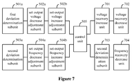
- Figure 7 is a schematic diagram of a third device embodiment of a grid-connected control device according to the present disclosure.
- the grid-connected control device further includes a voltage recovery increase unit 701 and a voltage recovery decrease unit 702.
- the voltage recovery increase unit 701 is configured to increase the set output voltage of the inverter with a fifth step size after the inverter is connected to the grid successfully in a case that the set output voltage of the inverter is decreased with the preset first step size before the inverter is connected to the grid, until a third deviation between the set output voltage of the inverter and the voltage of the grid falls within a second set voltage threshold, and set the set output voltage of the inverter to be the voltage of the grid.
- a load reactive power bore by the inverter will be transferred to the external grid gradually in a process of gradually increasing the set output voltage of the inverter.
- the first step size may or may not be equal to the fifth step size.
- the voltage recovery decrease unit 702 is configured to decrease the set output voltage of the inverter with a sixth step size after the inverter is connected to the grid successfully in a case that the set output voltage of the inverter is increased with the preset second step size before the inverter is connected to the grid, until a third deviation between the set output voltage of the inverter and the voltage of the grid falls within a second set voltage threshold, and set the set output voltage of the inverter to be the voltage of the grid.
- the load reactive power bore by the inverter will be transferred to the external grid gradually in a process of gradually decreasing the set output voltage of the inverter.
- the second step size may or may not be equal to the sixth step size.
- the grid-connected control device further includes a frequency recovery increase unit 703 and a frequency recovery decrease unit 704.
- the frequency recovery increase unit 703 is configured to increase the set output frequency of the inverter with a seventh step size after the inverter is connected to the grid successfully in a case that the set output frequency of the inverter is decreased with the preset third step size before the inverter is connected to the grid, until a fourth deviation between the set output frequency of the inverter and the frequency of the grid falls within a second set frequency threshold, and set the set output frequency of the inverter to be the frequency of the grid.
- a load active power bore by the inverter is transferred to the external grid gradually in a process of gradually increasing the set output frequency of the inverter.
- the third step size may or may not be equal to the seventh step size.
- the frequency recovery decrease unit 704 is configured to decrease the set output frequency of the inverter with an eighth step size after the inverter is connected to the grid successfully in a case that the set output frequency of the inverter is increased with the preset fourth step size before the inverter is connected to the grid, until a fourth deviation between the set output frequency of the inverter and the frequency of the grid falls within a second set frequency threshold, and set the set output frequency of the inverter to be the frequency of the grid.
- the load active power bore by the inverter is transferred to the external grid gradually in a process of gradually decreasing the set output frequency of the inverter.
- the fourth step size may or may not be equal to the eighth step size.
- the set output voltage and the set output frequency of the inverter may be recovered automatically after the inverter is connected to the grid successfully. It can be understood that, an object of recovering the set output voltage and the set output frequency of the inverter is smoothly transferring a load power bore by the inverter to the external grid, so that the inverter charges the battery as possible. Or else, the battery will continue to be lack of electricity.
- grid-connected control device embodiments according to the present disclosure described above, smooth grid-connected control can be ensured effectively in any parameter setting range, and it is effectively avoided a complicated process of resetting an operating parameter by the inverter every time before the inverter performs grid-connected operation.
- the grid-connected control device does not affect regulating performance of the energy-storage inverter in performing the off-grid operation. Parameter regulating such as power scheduling can be performed normally in the off-grid process, and the inverter can be connected to the grid successfully through the grid-connected voltage and frequency adjustment process as required.
Landscapes
- Engineering & Computer Science (AREA)
- Power Engineering (AREA)
- Inverter Devices (AREA)
- Supply And Distribution Of Alternating Current (AREA)
Abstract
Description
- The present disclosure relates to the field of inverter control technology, and particularly to a grid-connected control method based on a virtual synchronizer and a device thereof.
- Control on a virtual synchronizer has an advantage of droop control, and can realize droop adjustment control between a frequency and an active power and between a voltage and a reactive power. Also, the virtual synchronizer, which has an inertial component, can perform smooth adjustment on the frequency. An energy-storage inverter based on control of the virtual synchronizer has been widely adopted in an actual application.
- Before the energy-storage inverter based on the control of the virtual synchronizer performs grid-connected operation, it is determined whether an alternating-current voltage outputted from the energy-storage inverter is synchronous with a voltage of an external grid. Only in a case of a positive determination, the energy-storage inverter can be connected to the grid with reduced impact to the grid in a grid-connected process.
- Therefore, it is desired to provide a grid-connected control method for the energy-storage inverter, for successfully and smoothly connecting the energy-storage inverter to the grid without any impact to the grid.
- In order to solve the technical problem in the conventional technology, a grid-connected control method based on a virtual synchronizer and a device thereof are provided according to the present disclosure, for successfully and smoothly connecting an energy-storage inverter to the grid without any impact to the grid.
- A grid-connected control method based on a virtual synchronizer is provided according to an embodiment of the present disclosure. The grid-connected control method includes:
- detecting whether a first deviation between an output voltage of an inverter and a voltage of a grid exceeds a first set voltage threshold, and adjusting a set output voltage of the inverter in a case that it is detected that the first deviation exceeds the first set voltage threshold, so that the first deviation falls within the first set voltage threshold;
- detecting whether a second deviation between an output frequency of the inverter and a frequency of the grid exceeds a first set frequency threshold, and adjusting a set output frequency of the inverter in a case that it is detected that the second deviation exceeds the first set frequency threshold, so that the second deviation falls within the first set frequency threshold; and
- controlling the inverter to connect to the grid when a phase of a voltage of the grid is consistent with a phase of an output voltage of the inverter in a case that the first deviation falls within the first set voltage threshold and the second deviation falls within the first set frequency threshold.
- Preferably, the adjusting the set output voltage of the inverter in a case that it is detected that the first deviation exceeds the first set voltage threshold may include:
- decreasing the set output voltage of the inverter with a preset first step size in a case that the output voltage of the inverter is greater than the voltage of the grid; or
- increasing the set output voltage of the inverter with a preset second step size in a case that the output voltage of the inverter is less than the voltage of the grid.
- Preferably, the adjusting the set output frequency of the inverter in a case that it is detected that the second deviation exceeds the first set frequency threshold may include:
- decreasing the set output frequency of the inverter with a preset third step size in a case that the output frequency of the inverter is greater than the frequency of the grid; or
- increasing the set output frequency of the inverter with a preset fourth step size in a case that the output frequency of the inverter is less than the frequency of the grid.
- Preferably, after the inverter is connected to the grid successfully, the grid-connected control method may further include:
- increasing the set output voltage of the inverter with a fifth step size after the inverter is connected to the grid successfully in a case that the set output voltage of the inverter is decreased with the preset first step size before the inverter is connected to the grid, until a third deviation between the set output voltage of the inverter and the voltage of the grid falls within a second set voltage threshold, and setting the set output voltage of the inverter to be the voltage of the grid; or
- decreasing the set output voltage of the inverter with a sixth step size after the inverter is connected to the grid successfully in a case that the set output voltage of the inverter is increased with the preset second step size before the inverter is connected to the grid, until a third deviation between the set output voltage of the inverter and the voltage of the grid falls within a second set voltage threshold, and setting the set output voltage of the inverter to be the voltage of the grid.
- Preferably, after the inverter is connected to the grid successfully, the grid-connected control method may further include:
- increasing the set output frequency of the inverter with a seventh step size after the inverter is connected to the grid successfully in a case that the set output frequency of the inverter is decreased with the preset third step size before the inverter is connected to the grid, until a fourth deviation between the set output frequency of the inverter and the frequency of the grid falls within a second set frequency threshold, and setting the set output frequency of the inverter to be the frequency of the grid; or
- decreasing the set output frequency of the inverter with an eighth step size after the inverter is connected to the grid successfully in a case that the set output frequency of the inverter is increased with the preset fourth step size before the inverter is connected to the grid, until a fourth deviation between the set output frequency of the inverter and the frequency of the grid falls within a second set frequency threshold, and setting the set output frequency of the inverter to be the frequency of the grid.
- A grid-connected control device based on a virtual synchronizer is further provided according to an embodiment of the present disclosure. The grid-connected control device includes a first deviation determination unit, a set output voltage adjustment unit, a second deviation determination unit, a set output frequency adjustment unit and a control unit.
- The first deviation determination unit may be configured to detect whether a first deviation between an output voltage of the inverter and a voltage of a grid exceeds a first set voltage threshold.
- The set output voltage adjustment unit is configured to adjust the set output voltage of an inverter in a case that the first deviation exceeds the first set voltage threshold, so that the first deviation falls within the first set voltage threshold.
- The second deviation determination unit may be configured to determine whether a second deviation between an output frequency of the inverter and a frequency of a grid exceeds a first set frequency threshold.
- The set output frequency adjustment unit is configured to adjust a set output frequency of the inverter in a case that the second deviation exceeds the first set frequency threshold, so that the second deviation falls within the first set frequency threshold.
- The control unit may be configured to control the inverter to connect to the grid when a phase of a voltage of the grid is consistent with a phase of an output voltage of the inverter in a case that the first deviation falls within the first set voltage threshold and the second deviation falls within the first set frequency threshold.
- Preferably, the first deviation determination unit may include a first deviation determination subunit. The set output voltage adjustment unit may include a set output voltage decrease adjustment subunit and a set output voltage increase adjustment subunit.
- The first deviation determination subunit may be configured to determine whether the output voltage of the inverter is greater than the voltage of the grid in a case that the first deviation between the output voltage of the inverter and the voltage of the grid exceeds the first set voltage threshold.
- The set output voltage decrease adjustment subunit may be configured to decrease the set output voltage of the inverter with a preset first step size in a case that the output voltage of the inverter is greater than the voltage of the grid.
- The set output voltage increase adjustment subunit may be configured to increase the set output voltage of the inverter with a preset second step size in a case that the output voltage of the inverter is less than the voltage of the grid.
- Preferably, the second deviation determination unit may include a second deviation determination subunit. The set output frequency adjustment unit may include a set output frequency decrease adjustment subunit and a set output frequency increase adjustment subunit.
- The second deviation determination subunit may be configured to determine whether the output frequency of the inverter is greater than the frequency of the grid in a case that the second deviation between the output frequency of the inverter and the frequency of the grid exceeds the first set frequency threshold.
- The set output frequency decrease adjustment subunit may be configured to decrease the set output frequency of the inverter with a preset third step size in a case that the output frequency of the inverter is greater than the frequency of the grid.
- The set output frequency increase adjustment subunit may be configured to increase the set output frequency of the inverter with a preset fourth step size in a case that the output frequency of the inverter is less than the frequency of the grid.
- Preferably, the grid-connected control device may further include a voltage recovery increase unit and a voltage recovery decrease unit.
- The voltage recovery increase unit may be configured to increase the set output voltage with a fifth step size after the inverter is connected to the grid successfully in a case that the set output voltage is decreased with the preset first step size before the inverter is connected to the grid, until a third deviation between the set output voltage of the inverter and the voltage of the grid falls within a second set voltage threshold, and set the set output voltage of the inverter to be the voltage of the grid.
- The voltage recovery decrease unit may be configured to decrease the set output voltage with a sixth step size after the inverter is connected to the grid successfully in a case that the set output voltage is increased with the preset second step size before the inverter is connected to the grid, until a third deviation between the set output voltage of the inverter and the voltage of the grid falls within a second set voltage threshold, and set the set output voltage of the inverter to be the voltage of the grid.
- Preferably, the grid-connected control device may further include a frequency recovery increase unit and a frequency recovery decrease unit.
- The frequency recovery increase unit may be configured to increase the set output frequency of the inverter with a seventh step size after the inverter is connected to the grid successfully in a case that the set output frequency of the inverter is decreased with the preset third step size before the inverter is connected to the grid, until a fourth deviation between the set output frequency of the inverter and the frequency of the grid falls within a second set frequency threshold, and setting the set output frequency of the inverter to be the frequency of the grid.
- The frequency recovery decrease unit may be configured to decrease the set output frequency of the inverter with an eighth step size after the inverter is connected to the grid successfully in a case that the set output frequency of the inverter is increased with the preset fourth step size before the inverter is connected to the grid, until a fourth deviation between the set output frequency of the inverter and the frequency of the grid falls within a second set frequency threshold, and setting the set output frequency of the inverter to be the frequency of the grid.
- Compared with the conventional technology, the present has at least following advantages.
- The output voltage of the inverter is detected. It is considered that the voltage of the inverter is synchronous with the voltage of the grid only in a case that the first deviation between the output voltage of the inverter and the voltage of the grid falls within the first set voltage threshold; or else the output voltage of the inverter is adjusted by adjusting the set output voltage of the inverter. The output frequency of the inverter is detected. It is considered that the frequency of the inverter is synchronous with the frequency of the grid only in a case that the second deviation between the output frequency of the inverter and the frequency of the grid falls within the first set frequency threshold; or else the output frequency of the inverter is adjusted by adjusting the set output frequency of the inverter. Only in a case that the voltage and the frequency of the inverter are synchronous with the voltage and the frequency of the grid respectively, the inverter can be controlled to connect to the grid. In a case that either the voltage or the frequency of the inverter is asynchronous with the voltage or the frequency of the grid, impact is caused to the grid in a grid-connected process. In the grid-connected control method according to the embodiment, the inverter can be connected to the grid successfully without any impact to the grid. Further, after the grid is recovered and is connected to a micro gird for an energy-storage inverter, the grid-connected control method can ensure that a load power can be transferred to the external grid smoothly without any power impact to the external grid and the micro grid.
- The drawings to be used in the description of the embodiments of the disclosure or the conventional technology will be described briefly as follows, so that the technical solutions according to the embodiments of the present disclosure or according to the conventional technology will become clearer. It is apparent that the drawings in the following description only illustrate some embodiments of the present application. For those skilled in the art, other drawings may be obtained according to these drawings without any creative work.
-
Figure 1 is a schematic diagram of an application scenario of an energy-storage inverter according to the present disclosure; -
Figure 2 is a flow diagram of a first method embodiment of a grid-connected control method according to the present disclosure; -
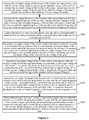
Figure 3 is a flow diagram of a second method embodiment of a grid-connected control method according to the present disclosure; -
Figure 4 is a flow diagram of a third method embodiment of a grid-connected control method according to the present disclosure; -
Figure 5 is a schematic diagram of a first device embodiment of a grid-connected control device according to the present disclosure; -
Figure 6 is a schematic diagram of a second device embodiment of a grid-connected control device according to the present disclosure; and -
Figure 7 is a schematic diagram of a third device embodiment of a grid-connected control device according to the present disclosure. - In order to make the skilled in the art understand the technical solution of the present disclosure better, the technical solution according to the embodiments of the present disclosure are described clearly and completely below in conjunction with the drawings in the embodiments of the present disclosure. It is apparent that the described embodiments are only a part rather than all of the embodiments. All other embodiments obtained by those skilled in the art without creative work based on the embodiments of the present disclosure will fall within the protection scope of the present disclosure.
- An application scenario of an energy-storage inverter is introduced first, so that the technology according to the present disclosure is understood better by those skilled in the art. Reference is made to
Figure 1 , which is a schematic diagram of an application scenario of the energy-storage inverter according to the present disclosure. - It is to be noted that, an inverter in the present disclosure refers to the energy-storage inverter, and is abbreviated as an inverter hereinafter. It can be understood that, there may be one energy-storage inverter, or multiple energy-storage inverters connected together. As shown in
Figure 1 , there are two energy-storage inverters T1 and Tn. All the energy-storage inverters have a same structure. - K is an access switch for an external grid.
- K1 is a synchronous switch at a micro-grid side in an intelligent coordination control cabinet.
- K2 is a synchronous switch at an external-grid side in the intelligent coordination control cabinet.
- K0 is an alternating-current output contactor of the energy-storage inverter.
- A detection control unit in the intelligent
coordination control cabinet 100 is configured to communicate with each of the energy-storage inverters, and perform synchronous logic determination in a connection process of the external grid to the micro grid, and control K2 to be turned on after the external grid becomes synchronous with the micro grid. - The inverter is configured to perform synchronous logic determination in a connection process of the micro grid to the external grid, and turn on the alternating-current output contactor thereof after the external grid becomes synchronous with the micro grid.
- A direct-current side of the inverter is connected with a battery. The battery is charged by a photovoltaic array via DC-DC. The photovoltaic array also provides a direct current for the direct-current side of the inverter.
- It can be understood that, DC-DC is a way of charging, by the energy-storage inverter, an accumulator when the accumulator is lack of electricity, which is not limited thereto.
- The grid-connected control method according to the present disclosure is applied to synchronize a voltage and a frequency of the energy-storage inverter with a voltage and a frequency of the grid, for successfully connecting the energy-storage inverter to the grid.
- Reference is made to
Figure 2 , which is a flow diagram of a first method embodiment of a grid-connected control method according to the present disclosure. - It can be understood that, since that synchronous between the energy-storage inverter and the grid not only includes voltage synchronization but also includes frequency synchronization, determination is made in terms of both a voltage and a frequency. The voltage represents an amplitude of the voltage, and the frequency represents a phase of the voltage. That is, the inverter can be connected to the grid only in a case that an amplitude and a phase of the voltage of the inverter are synchronous with an amplitude and a phase of a voltage of the grid respectively. In the present disclosure, the energy-storage inverter, which has a characteristic of droop control of the virtual synchronizer, can realize droop control between a frequency and an active power and between a voltage and an inactive power.
- The grid-connected control method based on a virtual synchronizer according to the embodiment includes steps S201 to S203.
- In step S201, it is detected whether a first deviation between an output voltage of an inverter and a voltage of a grid exceeds a first set voltage threshold, and a set output voltage of the inverter is adjusted in a case that it is detected that the first deviation exceeds the first set voltage threshold, so that the first deviation falls within the first set voltage threshold.
- It can be understood that, the first set voltage threshold is set as required, which is not defined in the present disclosure. In a case that the first deviation between the output voltage of the inverter and the voltage of the grid falls within the first set voltage threshold, it is considered that the first deviation falls within an allowable range, that is, the voltage of the inverter is synchronous with the voltage of the grid.
- In step S202, it is detected whether a second deviation between an output frequency of the inverter and a frequency of the grid exceeds a first set frequency threshold, and a set output frequency of the inverter is adjusted in a case that it is detected that the second deviation exceeds the first set frequency threshold, so that the second deviation falls within the first set frequency threshold.
- It can be understood that, the first set frequency threshold is set as required, which is not defined in the present disclosure. In a case that the second deviation between the output frequency of the inverter and the frequency of the grid falls within the first set frequency threshold, it is considered that the second deviation falls within an allowable range, that is, the frequency of the inverter is synchronous with the frequency of the grid.
- In step S203, the inverter is controlled to connect to the grid when a phase of a voltage of the grid is consistent with a phase of an output voltage of the inverter in a case that the first deviation falls within the first set voltage threshold and the second deviation falls within the first set frequency threshold.
- It can be understood that, the phase of the voltage of the grid being consistent with the phase of the output voltage of the inverter refers to that a phase difference between the phase of the voltage of the grid and the phase of the output voltage of the inverter falls within a preset phase range.
- Only in a case that the voltage and the frequency of the inverter are synchronous with the voltage and the frequency of the grid respectively, the inverter can be controlled to connect to the grid.
- In the grid-connected control method according to the present disclosure, the output voltage of the inverter is detected. It is considered that the voltage of the inverter is synchronous with the voltage of the grid only in a case that the first deviation between the output voltage of the inverter and the voltage of the grid falls within the first set voltage threshold; or else the output voltage of the inverter is adjusted by adjusting the set output voltage of the inverter. The output frequency of the inverter is detected. It is considered that the frequency of the inverter is synchronous with the frequency of the grid only in a case that the second deviation between the output frequency of the inverter and the frequency of the grid falls within the first set frequency threshold; or else the output frequency of the inverter is adjusted by adjusting the set output frequency of the inverter. Only in a case that the voltage and the frequency of the inverter are synchronous with the voltage and the frequency of the grid respectively, the inverter can be controlled to connect to the grid. In a case that either the voltage or the frequency of the inverter is asynchronous with the voltage or the frequency of the grid, impact is caused to the grid in a grid-connected process. In the grid-connected control method according to the embodiment, the inverter can be connected to the grid successfully without any impact to the grid. Further, after the grid is recovered and is connected to a micro gird for an energy-storage inverter, the grid-connected control method can ensure that a load power can be transferred to the external grid smoothly without any power impact to the external grid and the micro grid.
- Reference is made to
Figure 3 , which is a flow diagram of a second method embodiment of a grid-connected control method according to the present disclosure. - The grid-connected control method based on a virtual synchronizer according to the embodiment includes steps S301 to S303.
- Specifically, the adjusting the set output voltage of the inverter in a case that it is detected that the first deviation exceeds the first set voltage threshold includes step S301.
- In step S301, the set output voltage of the inverter is decreased with a preset first step size in a case that the output voltage of the inverter is greater than the voltage of the grid, or the set output voltage of the inverter is increased with a preset second step size in a case that the output voltage of the inverter is less than the voltage of the grid, so that the first deviation falls within the first set voltage threshold.
- It can be understood that, the first deviation may be an absolute value of a difference between the output voltage of the inverter and the voltage of the grid. When the first deviation exceeds the first set voltage threshold, it means that the output voltage of the inverter is greater than the voltage of the grid, or the output voltage of the inverter is less than the voltage of the grid.
- It is to be noted that the first step size may or may not be equal to the second step size.
- The adjusting the set output frequency of the inverter in a case that it is detected that the second deviation exceeds the first set frequency threshold includes step S302.
- In step S302, the set output frequency of the inverter is decreased with a preset third step size in a case that the output frequency of the inverter is greater than the frequency of the grid, or the set output frequency of the inverter is increased with a preset fourth step size in a case that the output frequency of the inverter is less than the frequency of the grid, so that the second deviation falls within the first set frequency threshold.
- It can be understood that, the second deviation may be an absolute value of a difference between the output frequency of the inverter and the frequency of the grid. When the second deviation exceeds the first set frequency threshold, it means that the output frequency of the inverter is greater than the frequency of the grid, or the output frequency of the inverter is less than the frequency of the grid.
- It is to be noted that the third step size may or may not be equal to the fourth step size.
- In step S303, the inverter is controlled to connect to the grid when a phase of a voltage of the grid is consistent with a phase of an output voltage of the inverter in a case that the first deviation falls within the first set voltage threshold and the second deviation falls within the first set frequency threshold.
- In the embodiment, in a case that the first deviation exceeds the first set voltage threshold, the output voltage of the inverter is synchronized with the voltage of the grid by adjusting the set output voltage of the inverter; and in a case that the second deviation exceeds the first set frequency threshold, the output frequency of the inverter is synchronized with a frequency of the grid by adjusting the set output frequency of the inverter, to prepare the inverter to successfully connect to the grid.
- It can be understood that, the control process in the first method embodiment and the control process in the second method embodiment are performed before the inverter is connected to the grid, and the set output voltage and the set output frequency of the inverter are recovered after the inverter is connected to the grid successfully, which is described in detail below in conjunction with a third method embodiment.
- Reference is made to
Figure 4 , which is a flow diagram of a third method embodiment of a grid-connected control method according to the present disclosure. - In the embodiment, steps S401 to S403 are the same as steps S301 to S303, respectively, which are not described here.
- After the inverter is connected to the grid successfully, the grid-connected control method further includes following steps S404 to S407.
- In step S404, the set output voltage of the inverter is increased with a fifth step size after the inverter is connected to the grid successfully in a case that the set output voltage of the inverter is decreased with the preset first step size before the inverter is connected to the grid, until a third deviation between the set output voltage of the inverter and the voltage of the grid falls within a second set voltage threshold; and the set output voltage of the inverter is set to be the voltage of the grid.
- A load reactive power bore by the inverter will be transferred to the external grid gradually in a process of gradually increasing the set output voltage of the inverter.
- It is to be noted that the first step size may or may not be equal to the fifth step size.
- In step S405, the set output voltage of the inverter is decreased with a sixth step size after the inverter is connected to the grid successfully in a case that the set output voltage of the inverter is increased with the preset second step size before the inverter is connected to the grid, until a third deviation between the set output voltage of the inverter and the voltage of the grid falls within a second set voltage threshold; and the set output voltage of the inverter is set to be the voltage of the grid.
- The load reactive power bore by the inverter will be transferred to the external grid gradually in a process of gradually decreasing the set output voltage of the inverter.
- It is to be noted that the second step size may or may not be equal to the sixth step size
- It is to be noted that there is no sequential order between the steps S404 and S405.
- It can be understood that, a reactive power outputted from the inverter will reach a set value in a case that the set output voltage of the inverter is set to be the voltage of the grid.
- In step S406, the set output frequency of the inverter is increased with a seventh step size after the inverter is connected to the grid successfully in a case that the set output frequency of the inverter is decreased with the preset third step size before the inverter is connected to the grid, until a fourth deviation between the set output frequency of the inverter and the frequency of the grid falls within a second set frequency threshold; and the set output frequency of the inverter is set to be the frequency of the grid.
- A load active power bore by the inverter is transferred to the external grid gradually in a process of gradually increasing the set output frequency of the inverter.
- It is to be noted that the third step size may or may not be equal to the seventh step size.
- In step S407, the set output frequency of the inverter is decreased with an eighth step size after the inverter is connected to the grid successfully in a case that the set output frequency of the inverter is increased with the preset fourth step size before the inverter is connected to the grid, until a fourth deviation between the set output frequency of the inverter and the frequency of the grid falls within a second set frequency threshold; and the set output frequency of the inverter is set to be the frequency of the grid.
- The load active power bore by the inverter is transferred to the external grid gradually in a process of gradually decreasing the set output frequency of the inverter.
- It is to be noted that the fourth step size may or may not be equal to the eighth step size.
- It is to be noted that there is no sequential order between steps S406 and S407.
- It can be understood that, after being recovered, the set output voltage and the set output frequency of the inverter will not be changed again until the inverter is started for a next time.
- In the grid-connected control method according to the embodiment, the set output voltage and the set output frequency of the inverter may be recovered automatically after the inverter is connected to the grid successfully. It can be understood that, an object of recovering the set output voltage and the set output frequency of the inverter is smoothly transferring a load power bore by the inverter to the external grid, so that the inverter charges the battery as possible. Or else, the battery will continue to be lack of electricity.
- With the grid-connected control method embodiments according to the present disclosure described above, smooth grid-connected control can be ensured effectively in any parameter setting range, and it is effectively avoided a complicated process of resetting an operating parameter by the inverter every time before the inverter performs grid-connected operation. Also, the grid-connected control method does not affect regulating performance of the energy-storage inverter in performing the off-grid operation. Parameter regulating such as power scheduling can be performed normally in the off-grid process, and the inverter can be connected to the grid successfully through the grid-connected voltage and frequency adjustment process as required.
- Based on the grid-connected control method based on the virtual synchronizer according to the above embodiments, the embodiment of the present disclosure further provides a grid-connected control device based on a virtual synchronizer, which is described in detail below in conjunction with drawings.
- Reference is made to
Figure 5 , which is a schematic diagram of a first device embodiment of a grid-connected control device according to the present disclosure. - It can be understood that, since that synchronous between the energy-storage inverter and the grid not only includes voltage synchronization but also includes frequency synchronization, determination is made in terms of both a voltage and a frequency. The voltage represents an amplitude of the voltage, and the frequency represents a phase of the voltage. That is, the inverter can be connected to the grid only in a case that an amplitude and a phase of the voltage of the inverter are synchronous with an amplitude and a phase of a voltage of the grid respectively. In the present disclosure, the energy-storage inverter, which has a characteristic of droop control of the virtual synchronizer, can realize droop control between a frequency and an active power and between a voltage and an inactive power.
- The grid-connected control device based on the virtual synchronizer according to the embodiment includes a first
deviation determination unit 501, a set outputvoltage adjustment unit 502, a seconddeviation determination unit 503, a set outputfrequency adjustment unit 504 and acontrol unit 505. - The first
deviation determination unit 501 is configured to detect whether a first deviation between an output voltage of an inverter and a voltage of a grid exceeds a first set voltage threshold. - It can be understood that, the first set voltage threshold is set as required, which is not defined in the present disclosure. In a case that the first deviation between the output voltage of the inverter and the voltage of the grid falls within the first set voltage threshold, it is considered that the first deviation falls within an allowable range, that is, the voltage of the inverter is synchronous with the voltage of the grid.
- The set output
voltage adjustment unit 502 is configured to adjust a set output voltage of the inverter in a case that it is detected that the first deviation exceeds the first set voltage threshold, so that the first deviation falls within the first set voltage threshold. - The second
deviation determination unit 503 is configured to detect whether the second deviation between the output frequency of the inverter and the frequency of the grid exceeds the first set frequency threshold. - It can be understood that, a first set frequency threshold is set as required, which is not defined in the present disclosure. In a case that the second deviation between the output frequency of the inverter and the frequency of the grid falls within the first set frequency threshold, it is considered that the second deviation falls within an allowable range, that is, the frequency of the inverter is synchronous with the frequency of the grid.
- The set output
frequency adjustment unit 504 is configured to adjust a set output frequency of the inverter is adjusted in a case that it is detected that the second deviation exceeds the first set frequency threshold, so that the second deviation falls within the first set frequency threshold. - The
control unit 505 is configured to control the inverter to connect to the grid when a phase of a voltage of the grid is consistent with a phase of an output voltage of the inverter in a case that the first deviation falls within the first set voltage threshold and the second deviation falls within the first set frequency threshold. - It can be understood that, the phase of the voltage of the grid being consistent with the phase of the output voltage of the inverter refers to that a phase difference between the phase of the voltage of the grid and the phase of the output voltage of the inverter falls within a preset phase range.
- Only in a case that the voltage and the frequency of the inverter are synchronous with the voltage and the frequency of the grid respectively, the inverter can be controlled to connect to the grid.
- In the grid-connected control device according to the present disclosure, the output voltage of the inverter is detected. It is considered that the voltage of the inverter is synchronous with the voltage of the grid only in a case that the first deviation between the output voltage of the inverter and the voltage of the grid falls within the first set voltage threshold; or else the output voltage of the inverter is adjusted by adjusting the set output voltage of the inverter. The output frequency of the inverter is detected. It is considered that the frequency of the inverter is synchronous with the frequency of the grid only in a case that the second deviation between the output frequency of the inverter and the frequency of the grid falls within the first set frequency threshold; or else the output frequency of the inverter is adjusted by adjusting the set output frequency of the inverter. Only in a case that the voltage and the frequency of the inverter are synchronous with the voltage and the frequency of the grid respectively, the inverter can be controlled to connect to the grid when it is determined that the phase difference between the phase of the voltage of the grid and the phase of the output voltage of the inverter meets the requirement. In a case that either the voltage or the frequency of the inverter is asynchronous with the voltage or the frequency of the grid, impact is caused to the grid in a grid-connected process. In the grid-connected control device according to the embodiment, the inverter can be connected to the grid successfully without any impact to the grid. Further, after the grid is recovered and is connected to a micro gird for an energy-storage inverter, the grid-connected control device can ensure that a load power can be transferred to the external grid smoothly without any power impact to the external grid and the micro grid.
- Reference is made to
Figure 6 , which is a schematic diagram of a second device embodiment of a grid-connected control device according to the present disclosure. - The first
deviation determination unit 501 includes a firstdeviation determination subunit 501a. The set outputvoltage adjustment unit 502 includes a set output voltagedecrease adjustment subunit 502a and a set output voltageincrease adjustment subunit 502b. - The first
deviation determination subunit 501a is configured to determine whether the output voltage of the inverter is greater than the voltage of the grid in a case that the first deviation between the output voltage of the inverter and the voltage of the grid exceeds the first set voltage threshold. - The set output voltage
decrease adjustment subunit 502a is configured to decrease the set output voltage of the inverter with a preset first step size in a case that the output voltage of the inverter is greater than the voltage of the grid. - The set output voltage
increase adjustment subunit 502b is configured to increase the set output voltage of the inverter with a preset second step size in a case that the output voltage of the inverter is less than the voltage of the grid. - It can be understood that, the first deviation may be an absolute value of a difference between the output voltage of the inverter and the voltage of the grid. When the first deviation exceeds the first set voltage threshold, it means that the output voltage of the inverter is greater than the voltage of the grid, or the output voltage of the inverter is less than the voltage of the grid.
- It is to be noted that the first step size may or may not be equal to the second step size.
- The second
deviation determination unit 503 includes a seconddeviation determination subunit 503a. The set outputfrequency adjustment unit 504 includes a set output frequencydecrease adjustment subunit 504a and a set output frequencyincrease adjustment subunit 504b. - The second
deviation determination subunit 503a is configured to determine whether the output frequency of the inverter is greater than the frequency of the grid in a case that the second deviation between the output frequency of the inverter and the frequency of the grid exceeds the first set frequency threshold. - The set output frequency
decrease adjustment subunit 504a is configured to decrease the set output frequency of the inverter with a preset third step size in a case that the output frequency of the inverter is greater than the frequency of the grid. - The set output frequency
increase adjustment subunit 504b is configured to increase the set output frequency of the inverter with a preset fourth step size in a case that the output frequency of the inverter is less than the frequency of the grid. - It can be understood that, the second deviation may be an absolute value of a difference between the output frequency of the inverter and the frequency of the grid. When the second deviation exceeds the first set frequency threshold, it means that the output frequency of the inverter is greater than the frequency of the grid, or the output frequency of the inverter is less than the frequency of the grid.
- It is to be noted that the third step size may or may not be equal to the fourth step size.
- In the embodiment, in a case that the first deviation exceeds the first set voltage threshold, an output voltage of the inverter is synchronized with a voltage of the grid by adjusting the set output voltage of the inverter; and in a case that the second deviation exceeds the first set frequency threshold, the output frequency of the inverter is synchronized with a frequency of the grid by adjusting the set output frequency of the inverter, to prepare the inverter to successfully connect to the grid.
- Reference is made to
Figure 7 , which is a schematic diagram of a third device embodiment of a grid-connected control device according to the present disclosure. - The grid-connected control device according to the embodiment further includes a voltage
recovery increase unit 701 and a voltagerecovery decrease unit 702. - The voltage
recovery increase unit 701 is configured to increase the set output voltage of the inverter with a fifth step size after the inverter is connected to the grid successfully in a case that the set output voltage of the inverter is decreased with the preset first step size before the inverter is connected to the grid, until a third deviation between the set output voltage of the inverter and the voltage of the grid falls within a second set voltage threshold, and set the set output voltage of the inverter to be the voltage of the grid. - A load reactive power bore by the inverter will be transferred to the external grid gradually in a process of gradually increasing the set output voltage of the inverter.
- It is to be noted that the first step size may or may not be equal to the fifth step size.
- The voltage
recovery decrease unit 702 is configured to decrease the set output voltage of the inverter with a sixth step size after the inverter is connected to the grid successfully in a case that the set output voltage of the inverter is increased with the preset second step size before the inverter is connected to the grid, until a third deviation between the set output voltage of the inverter and the voltage of the grid falls within a second set voltage threshold, and set the set output voltage of the inverter to be the voltage of the grid. - The load reactive power bore by the inverter will be transferred to the external grid gradually in a process of gradually decreasing the set output voltage of the inverter.
- It is to be noted that the second step size may or may not be equal to the sixth step size.
- The grid-connected control device according to the embodiment further includes a frequency
recovery increase unit 703 and a frequencyrecovery decrease unit 704. - The frequency
recovery increase unit 703 is configured to increase the set output frequency of the inverter with a seventh step size after the inverter is connected to the grid successfully in a case that the set output frequency of the inverter is decreased with the preset third step size before the inverter is connected to the grid, until a fourth deviation between the set output frequency of the inverter and the frequency of the grid falls within a second set frequency threshold, and set the set output frequency of the inverter to be the frequency of the grid. - A load active power bore by the inverter is transferred to the external grid gradually in a process of gradually increasing the set output frequency of the inverter.
- It is to be noted that the third step size may or may not be equal to the seventh step size.
- The frequency
recovery decrease unit 704 is configured to decrease the set output frequency of the inverter with an eighth step size after the inverter is connected to the grid successfully in a case that the set output frequency of the inverter is increased with the preset fourth step size before the inverter is connected to the grid, until a fourth deviation between the set output frequency of the inverter and the frequency of the grid falls within a second set frequency threshold, and set the set output frequency of the inverter to be the frequency of the grid. - The load active power bore by the inverter is transferred to the external grid gradually in a process of gradually decreasing the set output frequency of the inverter.
- It is to be noted that the fourth step size may or may not be equal to the eighth step size.
- It can be understood that, after being recovered, the set output voltage and the set output frequency of the inverter will not be changed again until the inverter is started for a next time.
- In the grid-connected control device according to the embodiment, the set output voltage and the set output frequency of the inverter may be recovered automatically after the inverter is connected to the grid successfully. It can be understood that, an object of recovering the set output voltage and the set output frequency of the inverter is smoothly transferring a load power bore by the inverter to the external grid, so that the inverter charges the battery as possible. Or else, the battery will continue to be lack of electricity.
- With the grid-connected control device embodiments according to the present disclosure described above, smooth grid-connected control can be ensured effectively in any parameter setting range, and it is effectively avoided a complicated process of resetting an operating parameter by the inverter every time before the inverter performs grid-connected operation. Also, the grid-connected control device does not affect regulating performance of the energy-storage inverter in performing the off-grid operation. Parameter regulating such as power scheduling can be performed normally in the off-grid process, and the inverter can be connected to the grid successfully through the grid-connected voltage and frequency adjustment process as required.
- What described above are only preferred embodiments of the present disclosure and is not intended to limit the present disclosure in any way. The preferred embodiments of the present disclosure are disclosed above, which should not be interpreted as limiting the present disclosure. Numerous alternations, modifications, and equivalents can be made to the technical solutions of the present disclosure by those skilled in the art in light of the methods and technical content disclosed herein without deviation from the scope of the present disclosure. Therefore, any alternations, modifications, and equivalents made to the embodiments above according to the technical essential of the present disclosure without deviation from the scope of the present disclosure should fall within the scope of protection of the present disclosure.
Claims (10)
- A grid-connected control method based on a virtual synchronizer, wherein the grid-connected control method comprises:detecting whether a first deviation between an output voltage of an inverter and a voltage of a grid exceeds a first set voltage threshold, and adjusting a set output voltage of the inverter in a case that it is detected that the first deviation exceeds the first set voltage threshold, so that the first deviation falls within the first set voltage threshold;detecting whether a second deviation between an output frequency of the inverter and a frequency of the grid exceeds a first set frequency threshold, and adjusting a set output frequency of the inverter in a case that it is detected that the second deviation exceeds the first set frequency threshold, so that the second deviation falls within the first set frequency threshold; andcontrolling the inverter to connect to the grid when a phase of a voltage of the grid is consistent with a phase of an output voltage of the inverter in a case that the first deviation falls within the first set voltage threshold and the second deviation falls within the first set frequency threshold.
- The grid-connected control method based on the virtual synchronizer according to claim 1, wherein the adjusting the set output voltage of the inverter in a case that it is detected that the first deviation exceeds the first set voltage threshold comprises:decreasing the set output voltage of the inverter with a preset first step size in a case that the output voltage of the inverter is greater than the voltage of the grid; orincreasing the set output voltage of the inverter with a preset second step size in a case that the output voltage of the inverter is less than the voltage of the grid.
- The grid-connected control method based on the virtual synchronizer according to claim 1, wherein the adjusting the set output frequency of the inverter in a case that it is detected that the second deviation exceeds the first set frequency threshold comprises:decreasing the set output frequency of the inverter with a preset third step size in a case that the output frequency of the inverter is greater than the frequency of the grid; orincreasing the set output frequency of the inverter with a preset fourth step size in a case that the output frequency of the inverter is less than the frequency of the grid.
- The grid-connected control method based on the virtual synchronizer according to any one of claims 1 to 3, wherein after the inverter is connected to the grid successfully, the grid-connected control method further comprises:increasing the set output voltage of the inverter with a fifth step size after the inverter is connected to the grid successfully in a case that the set output voltage of the inverter is decreased with the preset first step size before the inverter is connected to the grid, until a third deviation between the set output voltage of the inverter and the voltage of the grid falls within a second set voltage threshold, and setting the set output voltage of the inverter to be the voltage of the grid; ordecreasing the set output voltage of the inverter with a sixth step size after the inverter is connected to the grid successfully in a case that the set output voltage of the inverter is increased with the preset second step size before the inverter is connected to the grid, until a third deviation between the set output voltage of the inverter and the voltage of the grid falls within a second set voltage threshold, and setting the set output voltage of the inverter to be the voltage of the grid.
- The grid-connected control method based on the virtual synchronizer according to any one of claims 1 to 3, wherein after the inverter is connected to the grid successfully, the grid-connected control method further comprises:increasing the set output frequency of the inverter with a seventh step size after the inverter is connected to the grid successfully in a case that the set output frequency of the inverter is decreased with the preset third step size before the inverter is connected to the grid, until a fourth deviation between the set output frequency of the inverter and the frequency of the grid falls within a second set frequency threshold, and setting the set output frequency of the inverter to be the frequency of the grid; ordecreasing the set output frequency of the inverter with an eighth step size after the inverter is connected to the grid successfully in a case that the set output frequency of the inverter is increased with the preset fourth step size before the inverter is connected to the grid, until a fourth deviation between the set output frequency of the inverter and the frequency of the grid falls within a second set frequency threshold, and setting the set output frequency of the inverter to be the frequency of the grid.
- A grid-connected control device based on a virtual synchronizer, wherein the grid-connected control device comprises:a first deviation determination unit configured to detect whether a first deviation between an output voltage of an inverter and a voltage of a grid exceeds a first set voltage threshold;a set output voltage adjustment unit configured to adjust a set output voltage of the inverter in a case that the first deviation exceeds the first set voltage threshold, so that the first deviation falls within the first set voltage threshold;a second deviation determination unit configured to determine whether a second deviation between an output frequency of the inverter and a frequency of a grid exceeds a first set frequency threshold;a set output frequency adjustment unit configured to adjust a set output frequency of the inverter in a case that the second deviation exceeds the first set frequency threshold, so that the second deviation falls within the first set frequency threshold; anda control unit configured to control the inverter to connect to the grid when a phase of a voltage of the grid is consistent with a phase of an output voltage of the inverter in a case that the first deviation falls within the first set voltage threshold and the second deviation falls within the first set frequency threshold.
- The grid-connected control device according to claim 6, wherein
the first deviation determination unit comprises:a first deviation determination subunit configured to determine whether the output voltage of the inverter is greater than the voltage of the grid in a case that the first deviation between the output voltage of the inverter and the voltage of the grid exceeds the first set voltage threshold; andthe set output voltage adjustment unit comprises:a set output voltage decrease adjustment subunit configured to decrease the set output voltage of the inverter with a preset first step size in a case that the output voltage of the inverter is greater than the voltage of the grid, anda set output voltage increase adjustment subunit configured to increase the set output voltage of the inverter with a preset second step size in a case that the output voltage of the inverter is less than the voltage of the grid. - The grid-connected control device according to claim 6, wherein
the second deviation determination unit comprises:a second deviation determination subunit configured to determine whether the output frequency of the inverter is greater than the frequency of the grid in a case that the second deviation between the output frequency of the inverter and the frequency of the grid exceeds the first set frequency threshold; andthe set output frequency adjustment unit comprises:the set output frequency decrease adjustment subunit configured to decrease the set output frequency of the inverter with a preset third step size in a case that the output frequency of the inverter is greater than the frequency of the grid; andthe set output frequency increase adjustment subunit configured to increase the set output frequency of the inverter with a preset fourth step size in a case that the output frequency of the inverter is less than the frequency of the grid. - The grid-connected control device according to claim 6, further comprising:a voltage recovery increase unit configured to increase the set output voltage of the inverter with a fifth step size after the inverter is connected to the grid successfully in a case that the set output voltage of the inverter is decreased with the preset first step size before the inverter is connected to the grid, until a third deviation between the set output voltage of the inverter and the voltage of the grid falls within a second set voltage threshold, and set the set output voltage of the inverter to be the voltage of the grid; anda voltage recovery decrease unit configured to decrease the set output voltage of the inverter with a sixth step size after the inverter is connected to the grid successfully in a case that the set output voltage of the inverter is increased with the preset second step size before the inverter is connected to the grid, until a third deviation between the set output voltage of the inverter and the voltage of the grid falls within a second set voltage threshold, and set the set output voltage of the inverter to be the voltage of the grid.
- The grid-connected control device according to claim 6, further comprising:a frequency recovery increase unit configured to increase the set output frequency of the inverter with a seventh step size after the inverter is connected to the grid successfully in a case that the set output frequency of the inverter is decreased with the preset third step size before the inverter is connected to the grid, until a fourth deviation between the set output frequency of the inverter and the frequency of the grid falls within a second set frequency threshold, and set the set output frequency of the inverter to be the frequency of the grid; anda frequency recovery decrease unit configured to decrease the set output frequency of the inverter with an eighth step size after the inverter is connected to the grid successfully in a case that the set output frequency of the inverter is increased with the preset fourth step size before the inverter is connected to the grid, until a fourth deviation between the set output frequency of the inverter and the frequency of the grid falls within a second set frequency threshold, and set the set output frequency of the inverter to be the frequency of the grid.
Applications Claiming Priority (1)
| Application Number | Priority Date | Filing Date | Title |
|---|---|---|---|
| CN201511029011.3A CN105576697B (en) | 2015-12-30 | 2015-12-30 | Grid-connected control method based on virtual synchronous machine and device |
Publications (2)
| Publication Number | Publication Date |
|---|---|
| EP3188338A1 true EP3188338A1 (en) | 2017-07-05 |
| EP3188338B1 EP3188338B1 (en) | 2019-07-31 |
Family
ID=55886530
Family Applications (1)
| Application Number | Title | Priority Date | Filing Date |
|---|---|---|---|
| EP16177178.7A Active EP3188338B1 (en) | 2015-12-30 | 2016-06-30 | Grid-connected control method based on virtual synchronizer and device thereof |
Country Status (5)
| Country | Link |
|---|---|
| US (1) | US20170194793A1 (en) |
| EP (1) | EP3188338B1 (en) |
| JP (1) | JP2017121160A (en) |
| CN (1) | CN105576697B (en) |
| ES (1) | ES2751662T3 (en) |
Cited By (1)
| Publication number | Priority date | Publication date | Assignee | Title |
|---|---|---|---|---|
| CN110460102A (en) * | 2019-09-05 | 2019-11-15 | 广西师范大学 | A method for smooth switching control of microgrid based on current tracking algorithm |
Families Citing this family (20)
| Publication number | Priority date | Publication date | Assignee | Title |
|---|---|---|---|---|
| US10074985B2 (en) * | 2016-06-21 | 2018-09-11 | The Aerospace Corporation | Solar and/or wind inverter |
| CN106771879B (en) * | 2017-01-18 | 2020-08-28 | 阳光电源股份有限公司 | A power grid state detection method, device and static switch cabinet |
| GB2561577A (en) * | 2017-04-19 | 2018-10-24 | Mostyn Lavis Ian | Power conversion |
| CN108365636A (en) * | 2018-01-29 | 2018-08-03 | 湖南大学 | A kind of virtual synchronous generator control method |
| JP7025973B2 (en) * | 2018-03-28 | 2022-02-25 | 株式会社日立製作所 | Distributed generation controller |
| CN108964138B (en) * | 2018-07-27 | 2020-12-08 | 国家电网有限公司 | Synchronous grid connection method and system |
| CN109217376B (en) * | 2018-10-12 | 2020-07-07 | 西安许继电力电子技术有限公司 | A synchronous closing control method of subway brake regenerative converter |
| EP3644472A1 (en) * | 2018-10-23 | 2020-04-29 | Ian Lavis | Power conversion |
| CN109742814A (en) * | 2019-03-25 | 2019-05-10 | 山东理工大学 | A kind of electric car charge/discharge control method based on virtual inertia |
| CN111190061B (en) * | 2019-11-25 | 2022-07-15 | 平高集团有限公司 | A test platform for energy storage systems |
| CN110994689A (en) | 2019-12-31 | 2020-04-10 | 科华恒盛股份有限公司 | Method and system for switching grid connection to off-grid and energy storage converter |
| JP7480543B2 (en) * | 2020-03-23 | 2024-05-10 | 富士電機株式会社 | Distributed power source interconnection system and method, and power conditioner system |
| CN112003325B (en) * | 2020-08-24 | 2022-01-14 | 四川大学 | Method for smoothly cutting off pre-synchronous controller for grid connection of inverter |
| CN112994028B (en) * | 2021-05-24 | 2021-07-23 | 广东电网有限责任公司中山供电局 | Method and device for fast adjustment of reactive power and voltage in virtual power plant |
| CN114006466B (en) * | 2021-11-25 | 2025-06-24 | 国网上海市电力公司 | A seamless switching system and method for energy storage inverter based on large-capacity VSG |
| CN114552665B (en) * | 2022-02-24 | 2025-02-14 | 北京汇能精电科技股份有限公司 | Phase-locking device, method and phase-locking control system |
| CN116014756B (en) * | 2022-12-29 | 2025-08-22 | 国网河北省电力有限公司电力科学研究院 | Frequency support method, electronic equipment and storage medium for new energy grid-connected system |
| CN117595335B (en) * | 2023-10-19 | 2024-06-18 | 上海勘测设计研究院有限公司 | A control method and system for parallel operation of grid-connected energy storage converters |
| EP4641865A1 (en) * | 2024-04-26 | 2025-10-29 | Volvo Car Corporation | Startup control of generator |
| CN119341091B (en) * | 2024-10-29 | 2025-10-21 | 上海交通大学 | A grid-connected inverter stability control method and system suitable for extremely weak power grids |
Citations (12)
| Publication number | Priority date | Publication date | Assignee | Title |
|---|---|---|---|---|
| GB1250530A (en) * | 1968-01-04 | 1971-10-20 | ||
| GB1312726A (en) * | 1969-12-03 | 1973-04-04 | Automatic Switch Co | Automatic synchronizing monitor for parallel connection fo two separate alternating current sources |
| US20090108678A1 (en) * | 2007-10-31 | 2009-04-30 | Caterpillar Inc. | Power system with method for adding multiple generator sets |
| JP2009273206A (en) * | 2008-05-02 | 2009-11-19 | Meidensha Corp | Phase synchronization method for uninterruptible power supply unit |
| EP2348628A2 (en) * | 2010-01-25 | 2011-07-27 | Origin Electric Company Ltd | Synchronization detecting circuit and automatic synchronous parallelization apparatus |
| US20110216562A1 (en) * | 2010-03-14 | 2011-09-08 | Mechanical Electrical Systems, Inc. | Dc-to-dc power conversion |
| CN102723741A (en) * | 2012-04-26 | 2012-10-10 | 南京航空航天大学 | Grid connection presynchronization control method of microgrid inverter based on droop control |
| US20130293023A1 (en) * | 2012-04-30 | 2013-11-07 | Champion Power Equipment | Parallel linkage for generators |
| CN104578173A (en) * | 2015-01-26 | 2015-04-29 | 西安交通大学 | Inverter grid-connected control method based on virtual synchronous generator technology |
| CN104638643A (en) * | 2015-02-12 | 2015-05-20 | 清华大学 | Full-distributed secondary frequency modulation method for power system microgrid |
| CN104701886A (en) * | 2015-04-02 | 2015-06-10 | 国家电网公司 | Presynchronization control method based on virtual synchronous generator |
| CN104901322A (en) * | 2015-05-22 | 2015-09-09 | 国家电网公司 | Current transformer virtual synchronization control system under asymmetric power grid voltage and method thereof |
Family Cites Families (13)
| Publication number | Priority date | Publication date | Assignee | Title |
|---|---|---|---|---|
| JPS61288734A (en) * | 1985-06-14 | 1986-12-18 | 株式会社日立製作所 | automatic synchronizer |
| JPH0754907B2 (en) * | 1985-12-04 | 1995-06-07 | 富士通株式会社 | Microwave broadband oscillator |
| JPH1042476A (en) * | 1996-07-25 | 1998-02-13 | Meidensha Corp | Interconnecting apparatus |
| US6853940B2 (en) * | 2002-01-16 | 2005-02-08 | Ballard Power Systems Corporation | Anti-islanding device and method for grid connected inverters using random noise injection |
| US7120412B2 (en) * | 2002-05-31 | 2006-10-10 | Broadcom Corporation | Calibration circuit for VCO |
| US7183667B2 (en) * | 2003-12-19 | 2007-02-27 | Square D Company | Method and apparatus for power inverter synchronization |
| JP2010226871A (en) * | 2009-03-24 | 2010-10-07 | Toshiba Mitsubishi-Electric Industrial System Corp | Power supply system |
| US8217534B2 (en) * | 2009-05-20 | 2012-07-10 | General Electric Company | Power generator distributed inverter |
| CN102097823B (en) * | 2010-12-21 | 2013-04-24 | 山东电力集团公司烟台供电公司 | Two-stage three-phase photovoltaic grid-connected system without direct-current (DC) voltage sensor and control method of system |
| CN102355003B (en) * | 2011-09-13 | 2013-10-16 | 辽宁力迅风电控制系统有限公司 | Control method and device for single-phase grid-connected photovoltaic power generation system |
| US9337748B2 (en) * | 2013-08-02 | 2016-05-10 | Infineon Technologies Austria Ag | System and method for a DC-to-DC power converter with inverter stage coupled to the DC input |
| CN103795083B (en) * | 2014-02-20 | 2016-01-13 | 新疆希望电子有限公司 | Photovoltaic combining inverter grid-connected current soft start and soft stop method and system |
| CN105071443A (en) * | 2015-07-17 | 2015-11-18 | 上海电机学院 | Distributed power supply grid connection control method |
-
2015
- 2015-12-30 CN CN201511029011.3A patent/CN105576697B/en active Active
-
2016
- 2016-06-28 US US15/194,919 patent/US20170194793A1/en not_active Abandoned
- 2016-06-29 JP JP2016128422A patent/JP2017121160A/en active Pending
- 2016-06-30 EP EP16177178.7A patent/EP3188338B1/en active Active
- 2016-06-30 ES ES16177178T patent/ES2751662T3/en active Active
Patent Citations (12)
| Publication number | Priority date | Publication date | Assignee | Title |
|---|---|---|---|---|
| GB1250530A (en) * | 1968-01-04 | 1971-10-20 | ||
| GB1312726A (en) * | 1969-12-03 | 1973-04-04 | Automatic Switch Co | Automatic synchronizing monitor for parallel connection fo two separate alternating current sources |
| US20090108678A1 (en) * | 2007-10-31 | 2009-04-30 | Caterpillar Inc. | Power system with method for adding multiple generator sets |
| JP2009273206A (en) * | 2008-05-02 | 2009-11-19 | Meidensha Corp | Phase synchronization method for uninterruptible power supply unit |
| EP2348628A2 (en) * | 2010-01-25 | 2011-07-27 | Origin Electric Company Ltd | Synchronization detecting circuit and automatic synchronous parallelization apparatus |
| US20110216562A1 (en) * | 2010-03-14 | 2011-09-08 | Mechanical Electrical Systems, Inc. | Dc-to-dc power conversion |
| CN102723741A (en) * | 2012-04-26 | 2012-10-10 | 南京航空航天大学 | Grid connection presynchronization control method of microgrid inverter based on droop control |
| US20130293023A1 (en) * | 2012-04-30 | 2013-11-07 | Champion Power Equipment | Parallel linkage for generators |
| CN104578173A (en) * | 2015-01-26 | 2015-04-29 | 西安交通大学 | Inverter grid-connected control method based on virtual synchronous generator technology |
| CN104638643A (en) * | 2015-02-12 | 2015-05-20 | 清华大学 | Full-distributed secondary frequency modulation method for power system microgrid |
| CN104701886A (en) * | 2015-04-02 | 2015-06-10 | 国家电网公司 | Presynchronization control method based on virtual synchronous generator |
| CN104901322A (en) * | 2015-05-22 | 2015-09-09 | 国家电网公司 | Current transformer virtual synchronization control system under asymmetric power grid voltage and method thereof |
Cited By (2)
| Publication number | Priority date | Publication date | Assignee | Title |
|---|---|---|---|---|
| CN110460102A (en) * | 2019-09-05 | 2019-11-15 | 广西师范大学 | A method for smooth switching control of microgrid based on current tracking algorithm |
| CN110460102B (en) * | 2019-09-05 | 2023-04-25 | 广西师范大学 | Micro-grid smooth switching control method based on current tracking algorithm |
Also Published As
| Publication number | Publication date |
|---|---|
| CN105576697B (en) | 2018-09-28 |
| CN105576697A (en) | 2016-05-11 |
| JP2017121160A (en) | 2017-07-06 |
| ES2751662T3 (en) | 2020-04-01 |
| US20170194793A1 (en) | 2017-07-06 |
| EP3188338B1 (en) | 2019-07-31 |
Similar Documents
| Publication | Publication Date | Title |
|---|---|---|
| EP3188338B1 (en) | Grid-connected control method based on virtual synchronizer and device thereof | |
| KR101884621B1 (en) | Independent operation of multiple grid-connected power converters | |
| JP7008892B1 (en) | Control device and power converter | |
| CN109066785B (en) | Micro-grid real-time control method and micro-grid | |
| EP2965401B1 (en) | Alternating current (ac) synchronization for load restoration | |
| US11527966B2 (en) | Power conversion apparatus that judges system power failure based on system frequency and voltage | |
| WO2015096586A1 (en) | Seamless switching method and system for micro-grid system | |
| JP7773678B1 (en) | Multi-machine parallel energy storage system and its charge/discharge control method | |
| CN104065104A (en) | Micro grid rapid grid connection method based on three-phase independent regulation | |
| JP2017158264A (en) | Power supply system and power supply device | |
| EP4148946A1 (en) | Power converter | |
| US20240243578A1 (en) | Frequency regulation in an ac power supply system | |
| CN109599902B (en) | Synchronous presynchronization and synchronous closing detection control method and device for micro-grid | |
| EP4002636A1 (en) | Method and device for primary frequency control in electric power generation | |
| US12592564B2 (en) | DC-coupled photovoltaic power generation system, operating state switching method and device of DC-coupled photovoltaic power generation system | |
| JP7540238B2 (en) | Distributed power supply and control method thereof | |
| CN109687750B (en) | Control method, system and equipment of auxiliary power supply system | |
| CN108808712A (en) | A hybrid energy storage system power complementary control method and system | |
| EP4380034A2 (en) | Inverter and control method for inverter | |
| AU2023266342B2 (en) | System of machines connected in parallel, and method for transition between on-grid mode and off-grid mode | |
| US20240097472A1 (en) | Power supply/demand device, power generation system, and control method | |
| JP6985787B2 (en) | How to turn on the power converter and bypass circuit breaker | |
| EP4646773A1 (en) | Systems and methods for resynchronization of micro-grids with larger power grids | |
| CN121192914A (en) | A low-voltage standby automatic transfer control method and device compatible with photovoltaic and energy storage | |
| CN121965759A (en) | Double-winding generator and energy storage parallel system and grid-connected control method thereof |
Legal Events
| Date | Code | Title | Description |
|---|---|---|---|
| PUAI | Public reference made under article 153(3) epc to a published international application that has entered the european phase |
Free format text: ORIGINAL CODE: 0009012 |
|
| STAA | Information on the status of an ep patent application or granted ep patent |
Free format text: STATUS: THE APPLICATION HAS BEEN PUBLISHED |
|
| AK | Designated contracting states |
Kind code of ref document: A1 Designated state(s): AL AT BE BG CH CY CZ DE DK EE ES FI FR GB GR HR HU IE IS IT LI LT LU LV MC MK MT NL NO PL PT RO RS SE SI SK SM TR |
|
| AX | Request for extension of the european patent |
Extension state: BA ME |
|
| STAA | Information on the status of an ep patent application or granted ep patent |
Free format text: STATUS: REQUEST FOR EXAMINATION WAS MADE |
|
| 17P | Request for examination filed |
Effective date: 20171206 |
|
| RBV | Designated contracting states (corrected) |
Designated state(s): AL AT BE BG CH CY CZ DE DK EE ES FI FR GB GR HR HU IE IS IT LI LT LU LV MC MK MT NL NO PL PT RO RS SE SI SK SM TR |
|
| STAA | Information on the status of an ep patent application or granted ep patent |
Free format text: STATUS: EXAMINATION IS IN PROGRESS |
|
| 17Q | First examination report despatched |
Effective date: 20180821 |
|
| GRAP | Despatch of communication of intention to grant a patent |
Free format text: ORIGINAL CODE: EPIDOSNIGR1 |
|
| STAA | Information on the status of an ep patent application or granted ep patent |
Free format text: STATUS: GRANT OF PATENT IS INTENDED |
|
| INTG | Intention to grant announced |
Effective date: 20190108 |
|
| GRAS | Grant fee paid |
Free format text: ORIGINAL CODE: EPIDOSNIGR3 |
|
| GRAA | (expected) grant |
Free format text: ORIGINAL CODE: 0009210 |
|
| STAA | Information on the status of an ep patent application or granted ep patent |
Free format text: STATUS: THE PATENT HAS BEEN GRANTED |
|
| AK | Designated contracting states |
Kind code of ref document: B1 Designated state(s): AL AT BE BG CH CY CZ DE DK EE ES FI FR GB GR HR HU IE IS IT LI LT LU LV MC MK MT NL NO PL PT RO RS SE SI SK SM TR |
|
| REG | Reference to a national code |
Ref country code: CH Ref legal event code: EP Ref country code: GB Ref legal event code: FG4D |
|
| REG | Reference to a national code |
Ref country code: AT Ref legal event code: REF Ref document number: 1161962 Country of ref document: AT Kind code of ref document: T Effective date: 20190815 |
|
| REG | Reference to a national code |
Ref country code: IE Ref legal event code: FG4D |
|
| REG | Reference to a national code |
Ref country code: DE Ref legal event code: R096 Ref document number: 602016017609 Country of ref document: DE |
|
| REG | Reference to a national code |
Ref country code: NL Ref legal event code: MP Effective date: 20190731 |
|
| REG | Reference to a national code |
Ref country code: LT Ref legal event code: MG4D |
|
| REG | Reference to a national code |
Ref country code: AT Ref legal event code: MK05 Ref document number: 1161962 Country of ref document: AT Kind code of ref document: T Effective date: 20190731 |
|
| PG25 | Lapsed in a contracting state [announced via postgrant information from national office to epo] |
Ref country code: HR Free format text: LAPSE BECAUSE OF FAILURE TO SUBMIT A TRANSLATION OF THE DESCRIPTION OR TO PAY THE FEE WITHIN THE PRESCRIBED TIME-LIMIT Effective date: 20190731 Ref country code: LT Free format text: LAPSE BECAUSE OF FAILURE TO SUBMIT A TRANSLATION OF THE DESCRIPTION OR TO PAY THE FEE WITHIN THE PRESCRIBED TIME-LIMIT Effective date: 20190731 Ref country code: NL Free format text: LAPSE BECAUSE OF FAILURE TO SUBMIT A TRANSLATION OF THE DESCRIPTION OR TO PAY THE FEE WITHIN THE PRESCRIBED TIME-LIMIT Effective date: 20190731 Ref country code: SE Free format text: LAPSE BECAUSE OF FAILURE TO SUBMIT A TRANSLATION OF THE DESCRIPTION OR TO PAY THE FEE WITHIN THE PRESCRIBED TIME-LIMIT Effective date: 20190731 Ref country code: BG Free format text: LAPSE BECAUSE OF FAILURE TO SUBMIT A TRANSLATION OF THE DESCRIPTION OR TO PAY THE FEE WITHIN THE PRESCRIBED TIME-LIMIT Effective date: 20191031 Ref country code: PT Free format text: LAPSE BECAUSE OF FAILURE TO SUBMIT A TRANSLATION OF THE DESCRIPTION OR TO PAY THE FEE WITHIN THE PRESCRIBED TIME-LIMIT Effective date: 20191202 Ref country code: FI Free format text: LAPSE BECAUSE OF FAILURE TO SUBMIT A TRANSLATION OF THE DESCRIPTION OR TO PAY THE FEE WITHIN THE PRESCRIBED TIME-LIMIT Effective date: 20190731 Ref country code: AT Free format text: LAPSE BECAUSE OF FAILURE TO SUBMIT A TRANSLATION OF THE DESCRIPTION OR TO PAY THE FEE WITHIN THE PRESCRIBED TIME-LIMIT Effective date: 20190731 Ref country code: NO Free format text: LAPSE BECAUSE OF FAILURE TO SUBMIT A TRANSLATION OF THE DESCRIPTION OR TO PAY THE FEE WITHIN THE PRESCRIBED TIME-LIMIT Effective date: 20191031 |
|
| PG25 | Lapsed in a contracting state [announced via postgrant information from national office to epo] |
Ref country code: RS Free format text: LAPSE BECAUSE OF FAILURE TO SUBMIT A TRANSLATION OF THE DESCRIPTION OR TO PAY THE FEE WITHIN THE PRESCRIBED TIME-LIMIT Effective date: 20190731 Ref country code: GR Free format text: LAPSE BECAUSE OF FAILURE TO SUBMIT A TRANSLATION OF THE DESCRIPTION OR TO PAY THE FEE WITHIN THE PRESCRIBED TIME-LIMIT Effective date: 20191101 Ref country code: LV Free format text: LAPSE BECAUSE OF FAILURE TO SUBMIT A TRANSLATION OF THE DESCRIPTION OR TO PAY THE FEE WITHIN THE PRESCRIBED TIME-LIMIT Effective date: 20190731 Ref country code: AL Free format text: LAPSE BECAUSE OF FAILURE TO SUBMIT A TRANSLATION OF THE DESCRIPTION OR TO PAY THE FEE WITHIN THE PRESCRIBED TIME-LIMIT Effective date: 20190731 |
|
| PG25 | Lapsed in a contracting state [announced via postgrant information from national office to epo] |
Ref country code: TR Free format text: LAPSE BECAUSE OF FAILURE TO SUBMIT A TRANSLATION OF THE DESCRIPTION OR TO PAY THE FEE WITHIN THE PRESCRIBED TIME-LIMIT Effective date: 20190731 |
|
| REG | Reference to a national code |
Ref country code: ES Ref legal event code: FG2A Ref document number: 2751662 Country of ref document: ES Kind code of ref document: T3 Effective date: 20200401 |
|
| PG25 | Lapsed in a contracting state [announced via postgrant information from national office to epo] |
Ref country code: PL Free format text: LAPSE BECAUSE OF FAILURE TO SUBMIT A TRANSLATION OF THE DESCRIPTION OR TO PAY THE FEE WITHIN THE PRESCRIBED TIME-LIMIT Effective date: 20190731 Ref country code: DK Free format text: LAPSE BECAUSE OF FAILURE TO SUBMIT A TRANSLATION OF THE DESCRIPTION OR TO PAY THE FEE WITHIN THE PRESCRIBED TIME-LIMIT Effective date: 20190731 Ref country code: EE Free format text: LAPSE BECAUSE OF FAILURE TO SUBMIT A TRANSLATION OF THE DESCRIPTION OR TO PAY THE FEE WITHIN THE PRESCRIBED TIME-LIMIT Effective date: 20190731 Ref country code: IT Free format text: LAPSE BECAUSE OF FAILURE TO SUBMIT A TRANSLATION OF THE DESCRIPTION OR TO PAY THE FEE WITHIN THE PRESCRIBED TIME-LIMIT Effective date: 20190731 Ref country code: RO Free format text: LAPSE BECAUSE OF FAILURE TO SUBMIT A TRANSLATION OF THE DESCRIPTION OR TO PAY THE FEE WITHIN THE PRESCRIBED TIME-LIMIT Effective date: 20190731 |
|
| PG25 | Lapsed in a contracting state [announced via postgrant information from national office to epo] |
Ref country code: SM Free format text: LAPSE BECAUSE OF FAILURE TO SUBMIT A TRANSLATION OF THE DESCRIPTION OR TO PAY THE FEE WITHIN THE PRESCRIBED TIME-LIMIT Effective date: 20190731 Ref country code: SK Free format text: LAPSE BECAUSE OF FAILURE TO SUBMIT A TRANSLATION OF THE DESCRIPTION OR TO PAY THE FEE WITHIN THE PRESCRIBED TIME-LIMIT Effective date: 20190731 Ref country code: IS Free format text: LAPSE BECAUSE OF FAILURE TO SUBMIT A TRANSLATION OF THE DESCRIPTION OR TO PAY THE FEE WITHIN THE PRESCRIBED TIME-LIMIT Effective date: 20200224 Ref country code: CZ Free format text: LAPSE BECAUSE OF FAILURE TO SUBMIT A TRANSLATION OF THE DESCRIPTION OR TO PAY THE FEE WITHIN THE PRESCRIBED TIME-LIMIT Effective date: 20190731 |
|
| REG | Reference to a national code |
Ref country code: DE Ref legal event code: R097 Ref document number: 602016017609 Country of ref document: DE |
|
| PLBE | No opposition filed within time limit |
Free format text: ORIGINAL CODE: 0009261 |
|
| STAA | Information on the status of an ep patent application or granted ep patent |
Free format text: STATUS: NO OPPOSITION FILED WITHIN TIME LIMIT |
|
| PG2D | Information on lapse in contracting state deleted |
Ref country code: IS |
|
| PG25 | Lapsed in a contracting state [announced via postgrant information from national office to epo] |
Ref country code: IS Free format text: LAPSE BECAUSE OF FAILURE TO SUBMIT A TRANSLATION OF THE DESCRIPTION OR TO PAY THE FEE WITHIN THE PRESCRIBED TIME-LIMIT Effective date: 20191030 |
|
| 26N | No opposition filed |
Effective date: 20200603 |
|
| PG25 | Lapsed in a contracting state [announced via postgrant information from national office to epo] |
Ref country code: SI Free format text: LAPSE BECAUSE OF FAILURE TO SUBMIT A TRANSLATION OF THE DESCRIPTION OR TO PAY THE FEE WITHIN THE PRESCRIBED TIME-LIMIT Effective date: 20190731 |
|
| PG25 | Lapsed in a contracting state [announced via postgrant information from national office to epo] |
Ref country code: MC Free format text: LAPSE BECAUSE OF FAILURE TO SUBMIT A TRANSLATION OF THE DESCRIPTION OR TO PAY THE FEE WITHIN THE PRESCRIBED TIME-LIMIT Effective date: 20190731 |
|
| REG | Reference to a national code |
Ref country code: CH Ref legal event code: PL |
|
| PG25 | Lapsed in a contracting state [announced via postgrant information from national office to epo] |
Ref country code: LU Free format text: LAPSE BECAUSE OF NON-PAYMENT OF DUE FEES Effective date: 20200630 |
|
| REG | Reference to a national code |
Ref country code: BE Ref legal event code: MM Effective date: 20200630 |
|
| PG25 | Lapsed in a contracting state [announced via postgrant information from national office to epo] |
Ref country code: CH Free format text: LAPSE BECAUSE OF NON-PAYMENT OF DUE FEES Effective date: 20200630 Ref country code: LI Free format text: LAPSE BECAUSE OF NON-PAYMENT OF DUE FEES Effective date: 20200630 Ref country code: IE Free format text: LAPSE BECAUSE OF NON-PAYMENT OF DUE FEES Effective date: 20200630 Ref country code: FR Free format text: LAPSE BECAUSE OF NON-PAYMENT OF DUE FEES Effective date: 20200630 |
|
| PG25 | Lapsed in a contracting state [announced via postgrant information from national office to epo] |
Ref country code: BE Free format text: LAPSE BECAUSE OF NON-PAYMENT OF DUE FEES Effective date: 20200630 |
|
| PG25 | Lapsed in a contracting state [announced via postgrant information from national office to epo] |
Ref country code: MT Free format text: LAPSE BECAUSE OF FAILURE TO SUBMIT A TRANSLATION OF THE DESCRIPTION OR TO PAY THE FEE WITHIN THE PRESCRIBED TIME-LIMIT Effective date: 20190731 Ref country code: CY Free format text: LAPSE BECAUSE OF FAILURE TO SUBMIT A TRANSLATION OF THE DESCRIPTION OR TO PAY THE FEE WITHIN THE PRESCRIBED TIME-LIMIT Effective date: 20190731 |
|
| PG25 | Lapsed in a contracting state [announced via postgrant information from national office to epo] |
Ref country code: MK Free format text: LAPSE BECAUSE OF FAILURE TO SUBMIT A TRANSLATION OF THE DESCRIPTION OR TO PAY THE FEE WITHIN THE PRESCRIBED TIME-LIMIT Effective date: 20190731 |
|
| P01 | Opt-out of the competence of the unified patent court (upc) registered |
Effective date: 20230426 |
|
| PGFP | Annual fee paid to national office [announced via postgrant information from national office to epo] |
Ref country code: DE Payment date: 20250617 Year of fee payment: 10 |
|
| PGFP | Annual fee paid to national office [announced via postgrant information from national office to epo] |
Ref country code: GB Payment date: 20250625 Year of fee payment: 10 |
|
| PGFP | Annual fee paid to national office [announced via postgrant information from national office to epo] |
Ref country code: ES Payment date: 20250827 Year of fee payment: 10 |