EP3188282A1 - Electricity storage device - Google Patents
Electricity storage device Download PDFInfo
- Publication number
- EP3188282A1 EP3188282A1 EP15837025.4A EP15837025A EP3188282A1 EP 3188282 A1 EP3188282 A1 EP 3188282A1 EP 15837025 A EP15837025 A EP 15837025A EP 3188282 A1 EP3188282 A1 EP 3188282A1
- Authority
- EP
- European Patent Office
- Prior art keywords
- electricity storage
- harness
- case
- wire harness
- storage modules
- Prior art date
- Legal status (The legal status is an assumption and is not a legal conclusion. Google has not performed a legal analysis and makes no representation as to the accuracy of the status listed.)
- Granted
Links
- 230000005611 electricity Effects 0.000 title claims abstract description 241
- 238000013016 damping Methods 0.000 claims abstract description 25
- 239000000463 material Substances 0.000 claims abstract description 25
- 210000000352 storage cell Anatomy 0.000 claims abstract description 6
- 238000009792 diffusion process Methods 0.000 claims description 4
- 238000003780 insertion Methods 0.000 claims description 3
- 230000037431 insertion Effects 0.000 claims description 3
- 239000003507 refrigerant Substances 0.000 description 13
- 238000001514 detection method Methods 0.000 description 11
- 238000007599 discharging Methods 0.000 description 10
- 210000004027 cell Anatomy 0.000 description 9
- HBBGRARXTFLTSG-UHFFFAOYSA-N Lithium ion Chemical compound [Li+] HBBGRARXTFLTSG-UHFFFAOYSA-N 0.000 description 6
- 229910001416 lithium ion Inorganic materials 0.000 description 6
- 230000002265 prevention Effects 0.000 description 5
- 239000000758 substrate Substances 0.000 description 4
- 239000003990 capacitor Substances 0.000 description 3
- 238000000034 method Methods 0.000 description 3
- 229920002943 EPDM rubber Polymers 0.000 description 2
- 230000000694 effects Effects 0.000 description 2
- 238000007689 inspection Methods 0.000 description 2
- 238000012423 maintenance Methods 0.000 description 2
- 229910052751 metal Inorganic materials 0.000 description 2
- 239000002184 metal Substances 0.000 description 2
- 239000011347 resin Substances 0.000 description 2
- 229920005989 resin Polymers 0.000 description 2
- 238000005476 soldering Methods 0.000 description 2
- 238000000638 solvent extraction Methods 0.000 description 2
- 230000001629 suppression Effects 0.000 description 2
- PXHVJJICTQNCMI-UHFFFAOYSA-N Nickel Chemical compound [Ni] PXHVJJICTQNCMI-UHFFFAOYSA-N 0.000 description 1
- 238000010521 absorption reaction Methods 0.000 description 1
- 230000003213 activating effect Effects 0.000 description 1
- OJIJEKBXJYRIBZ-UHFFFAOYSA-N cadmium nickel Chemical compound [Ni].[Cd] OJIJEKBXJYRIBZ-UHFFFAOYSA-N 0.000 description 1
- 238000002485 combustion reaction Methods 0.000 description 1
- 238000006073 displacement reaction Methods 0.000 description 1
- 239000013013 elastic material Substances 0.000 description 1
- 239000003792 electrolyte Substances 0.000 description 1
- 238000009434 installation Methods 0.000 description 1
- 238000011835 investigation Methods 0.000 description 1
- 238000012986 modification Methods 0.000 description 1
- 230000004048 modification Effects 0.000 description 1
- 238000012544 monitoring process Methods 0.000 description 1
- 229910000652 nickel hydride Inorganic materials 0.000 description 1
Images


Classifications
-
- H—ELECTRICITY
- H02—GENERATION; CONVERSION OR DISTRIBUTION OF ELECTRIC POWER
- H02G—INSTALLATION OF ELECTRIC CABLES OR LINES, OR OF COMBINED OPTICAL AND ELECTRIC CABLES OR LINES
- H02G15/00—Cable fittings
- H02G15/08—Cable junctions
-
- H—ELECTRICITY
- H01—ELECTRIC ELEMENTS
- H01G—CAPACITORS; CAPACITORS, RECTIFIERS, DETECTORS, SWITCHING DEVICES OR LIGHT-SENSITIVE DEVICES, OF THE ELECTROLYTIC TYPE
- H01G11/00—Hybrid capacitors, i.e. capacitors having different positive and negative electrodes; Electric double-layer [EDL] capacitors; Processes for the manufacture thereof or of parts thereof
- H01G11/10—Multiple hybrid or EDL capacitors, e.g. arrays or modules
-
- H—ELECTRICITY
- H01—ELECTRIC ELEMENTS
- H01G—CAPACITORS; CAPACITORS, RECTIFIERS, DETECTORS, SWITCHING DEVICES OR LIGHT-SENSITIVE DEVICES, OF THE ELECTROLYTIC TYPE
- H01G11/00—Hybrid capacitors, i.e. capacitors having different positive and negative electrodes; Electric double-layer [EDL] capacitors; Processes for the manufacture thereof or of parts thereof
- H01G11/78—Cases; Housings; Encapsulations; Mountings
-
- H—ELECTRICITY
- H01—ELECTRIC ELEMENTS
- H01M—PROCESSES OR MEANS, e.g. BATTERIES, FOR THE DIRECT CONVERSION OF CHEMICAL ENERGY INTO ELECTRICAL ENERGY
- H01M50/00—Constructional details or processes of manufacture of the non-active parts of electrochemical cells other than fuel cells, e.g. hybrid cells
- H01M50/20—Mountings; Secondary casings or frames; Racks, modules or packs; Suspension devices; Shock absorbers; Transport or carrying devices; Holders
- H01M50/204—Racks, modules or packs for multiple batteries or multiple cells
- H01M50/207—Racks, modules or packs for multiple batteries or multiple cells characterised by their shape
- H01M50/213—Racks, modules or packs for multiple batteries or multiple cells characterised by their shape adapted for cells having curved cross-section, e.g. round or elliptic
-
- H—ELECTRICITY
- H01—ELECTRIC ELEMENTS
- H01M—PROCESSES OR MEANS, e.g. BATTERIES, FOR THE DIRECT CONVERSION OF CHEMICAL ENERGY INTO ELECTRICAL ENERGY
- H01M50/00—Constructional details or processes of manufacture of the non-active parts of electrochemical cells other than fuel cells, e.g. hybrid cells
- H01M50/20—Mountings; Secondary casings or frames; Racks, modules or packs; Suspension devices; Shock absorbers; Transport or carrying devices; Holders
- H01M50/233—Mountings; Secondary casings or frames; Racks, modules or packs; Suspension devices; Shock absorbers; Transport or carrying devices; Holders characterised by physical properties of casings or racks, e.g. dimensions
- H01M50/24—Mountings; Secondary casings or frames; Racks, modules or packs; Suspension devices; Shock absorbers; Transport or carrying devices; Holders characterised by physical properties of casings or racks, e.g. dimensions adapted for protecting batteries from their environment, e.g. from corrosion
-
- H—ELECTRICITY
- H01—ELECTRIC ELEMENTS
- H01M—PROCESSES OR MEANS, e.g. BATTERIES, FOR THE DIRECT CONVERSION OF CHEMICAL ENERGY INTO ELECTRICAL ENERGY
- H01M50/00—Constructional details or processes of manufacture of the non-active parts of electrochemical cells other than fuel cells, e.g. hybrid cells
- H01M50/20—Mountings; Secondary casings or frames; Racks, modules or packs; Suspension devices; Shock absorbers; Transport or carrying devices; Holders
- H01M50/233—Mountings; Secondary casings or frames; Racks, modules or packs; Suspension devices; Shock absorbers; Transport or carrying devices; Holders characterised by physical properties of casings or racks, e.g. dimensions
- H01M50/242—Mountings; Secondary casings or frames; Racks, modules or packs; Suspension devices; Shock absorbers; Transport or carrying devices; Holders characterised by physical properties of casings or racks, e.g. dimensions adapted for protecting batteries against vibrations, collision impact or swelling
-
- H—ELECTRICITY
- H01—ELECTRIC ELEMENTS
- H01M—PROCESSES OR MEANS, e.g. BATTERIES, FOR THE DIRECT CONVERSION OF CHEMICAL ENERGY INTO ELECTRICAL ENERGY
- H01M50/00—Constructional details or processes of manufacture of the non-active parts of electrochemical cells other than fuel cells, e.g. hybrid cells
- H01M50/20—Mountings; Secondary casings or frames; Racks, modules or packs; Suspension devices; Shock absorbers; Transport or carrying devices; Holders
- H01M50/249—Mountings; Secondary casings or frames; Racks, modules or packs; Suspension devices; Shock absorbers; Transport or carrying devices; Holders specially adapted for aircraft or vehicles, e.g. cars or trains
-
- H—ELECTRICITY
- H01—ELECTRIC ELEMENTS
- H01M—PROCESSES OR MEANS, e.g. BATTERIES, FOR THE DIRECT CONVERSION OF CHEMICAL ENERGY INTO ELECTRICAL ENERGY
- H01M50/00—Constructional details or processes of manufacture of the non-active parts of electrochemical cells other than fuel cells, e.g. hybrid cells
- H01M50/20—Mountings; Secondary casings or frames; Racks, modules or packs; Suspension devices; Shock absorbers; Transport or carrying devices; Holders
- H01M50/298—Mountings; Secondary casings or frames; Racks, modules or packs; Suspension devices; Shock absorbers; Transport or carrying devices; Holders characterised by the wiring of battery packs
-
- H—ELECTRICITY
- H05—ELECTRIC TECHNIQUES NOT OTHERWISE PROVIDED FOR
- H05K—PRINTED CIRCUITS; CASINGS OR CONSTRUCTIONAL DETAILS OF ELECTRIC APPARATUS; MANUFACTURE OF ASSEMBLAGES OF ELECTRICAL COMPONENTS
- H05K5/00—Casings, cabinets or drawers for electric apparatus
- H05K5/0017—Casings, cabinets or drawers for electric apparatus with operator interface units
-
- Y—GENERAL TAGGING OF NEW TECHNOLOGICAL DEVELOPMENTS; GENERAL TAGGING OF CROSS-SECTIONAL TECHNOLOGIES SPANNING OVER SEVERAL SECTIONS OF THE IPC; TECHNICAL SUBJECTS COVERED BY FORMER USPC CROSS-REFERENCE ART COLLECTIONS [XRACs] AND DIGESTS
- Y02—TECHNOLOGIES OR APPLICATIONS FOR MITIGATION OR ADAPTATION AGAINST CLIMATE CHANGE
- Y02E—REDUCTION OF GREENHOUSE GAS [GHG] EMISSIONS, RELATED TO ENERGY GENERATION, TRANSMISSION OR DISTRIBUTION
- Y02E60/00—Enabling technologies; Technologies with a potential or indirect contribution to GHG emissions mitigation
- Y02E60/10—Energy storage using batteries
Definitions
- the present invention relates to an electricity storage device in which a plurality of electricity storage modules are housed.
- An electricity storage device as a power source, is mounted on electric vehicles, hybrid vehicles, and the like.
- a plurality of electricity storage modules each including a plurality of secondary battery cells, such as lithium-ion secondary battery cells, are arranged and housed.
- the electricity storage modules are electrically connected via wire harnesses connected to external terminals.
- a large current flows in the wire harnesses when charging/discharging the electricity storage device, and thus, the wire harnesses are members having large thicknesses and small resistances.
- a power-supply device in which a plurality of holder cases, each housing a predetermined plurality number of electricity storage modules, are housed in an outer case.
- the power-supply device has a structure in which concave parts are provided on the respective holder cases and a power-supply line formed of a metal plate is fit into the concave parts.
- an electricity storage device including: a plurality of electricity storage modules, each including an electricity storage module case, a plurality of electricity storage cells housed in the electricity storage module case, and external terminals of positive and negative electrodes; an electricity storage case in which the plurality of electricity storage modules are arranged and housed; a plurality of wire harnesses connected to the external terminals of the positive and negative electrodes of the electricity storage modules; and a vibration damping material provided in a space region between one surface of the electricity storage case and, among the plurality of wire harnesses, at least a wire harness including the longest length extending in an arrangement direction of the electricity storage modules, wherein the wire harness including the longest length extending in the arrangement direction of the electricity storage modules is biased toward a side of the electricity storage module case by the one surface of the electricity storage case, through the vibration damping material.
- the electricity storage device is applied to an in-vehicle power-supply device in a motor drive system of a motor-driven vehicle, for example, an electric vehicle.
- the concept of the electric vehicle includes a hybrid electric vehicle including an engine that is an internal-combustion engine, and a motor, as a driving source of the vehicle, and a pure electric vehicle using a motor as a sole driving source of the vehicle, and the like.
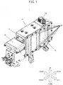
- FIG. 1 is an external perspective view of the embodiment of the electricity storage device according to the present invention
- FIG. 2 is an exploded perspective view of the electricity storage device illustrated in FIG. 1
- An electricity storage device 1 is, for example, a lithium-ion battery device, and a plurality of electricity storage modules 40A to 40C, each including a plurality of secondary battery cells (electricity storage cells) 101, such as lithium-ion secondary battery cells, (refer to FIGs. 5A and 5B ) is housed in an electricity storage case 2 that is a housing of the electricity storage device 1.
- the electricity storage case 2 has a shape in which a small rectangular parallelepiped is connected to the front side of a large rectangular parallelepiped.
- FIG. 1 and FIG. 2 a front-rear direction, a left-right direction, and an up-down direction will be described as directions illustrated in FIG. 1 and FIG. 2 .
- Each direction illustrated in FIG. 1 and FIG. 2 corresponds to the front-rear direction, the left-right direction, and the up-down direction in a vehicle on which the electricity storage device 1 is mounted, respectively.
- the electricity storage case 2 includes a main case 11, a side cover 12, a bottom cover 13, and a top cover 14.
- the main case 11 is a member having a frame shape in which the upper part, the lower part, and the left part open.
- Each of the main case 11, the side cover 12, the bottom cover 13, and the top cover 14 is formed by pressing a metal thin plate, for example.
- the side cover 12 is a member arranged to be opposed to a right wall 11a of the main case 11, constitutes a left wall, and closes the opening of the left part of the main case 11.
- Through holes 12a into which bolts 81 to be described below, which are through bolts, are to be inserted are provided in the side cover 12.
- the bottom cover 13 is a member that closes the opening of the lower part of the main case 11, and the top cover 14 is a member that closes the opening of the upper part of the main case 11.
- Each of the side cover 12, the bottom cover 13, and the top cover 14 is fixed to the main case 11 with fastening members, such as bolts, to form a space for housing electronic components therein.
- an electricity storage module-housing area 2A in which the electricity storage modules 40A to 40C are to be housed, and a control unit-housing area 2B in which a junction box 3 is to be housed are formed.
- the junction box 3 is a control circuit that measures a charge/discharge current, outputs a signal, and has a precharge function to suppress an inrush current into a capacitor of an inverter when activating a vehicle.
- each of the electricity storage modules 40A to 40C has a block shape of a rectangular parallelepiped.
- each of the electricity storage modules 40A to 40C is housed to be arranged adjacent to and in parallel with one another in the front-rear direction with the longitudinal directions thereof extending in the up-down direction in the main case 11.
- Each of the electricity storage modules 40A to 40C is arranged linearly at predetermined intervals in order of the electricity storage modules 40A, 40B, and 40C in a direction away from the control unit-housing area 2B, i.e., to the rear direction.
- the electricity storage modules 40A to 40C will be collectively described as an electricity storage module 40, appropriately.
- the electricity storage module 40 is fixed to the main case 11 with the bolts 81 together with the side cover 12.
- Back nuts 82 to be fastened to the bolts 81 (refer to FIG. 10B ) are welded to be fixed to the right-side surface of the right wall 11a of the main case 11.
- a lithium-ion battery controller (hereinafter, LBC) 4 is disposed above the control unit-housing area 2B.
- the LBC 4 is a control circuit for measuring, monitoring, and controlling a voltage, a current, a temperature, charge/discharge, and the like for the electricity storage module 40 and each cell, and is covered with a LBC cover 15.
- the electricity storage module-housing area 2A and the control unit-housing area 2B of the electricity storage case 2 are partitioned by a partitioning member 80.
- a SD (service disconnect) switch 53 is inserted into an opening of the top cover 14 to project outward from the top cover 14 of the electricity storage case 2.
- FIG. 3 is a perspective view of the electricity storage module illustrated in FIG. 2
- FIG. 4 is a schematic external perspective view of the electricity storage module illustrated in FIG. 3
- FIG. 5A is an exploded perspective view for describing the structure of the electricity storage module illustrated in FIG. 3
- FIG. 5B is a schematic external perspective view of the electricity storage module.
- a refrigerant inlet port 116 is provided on the left part of each of the electricity storage modules 40A to 40C.
- a refrigerant outlet port 118 is provided on the right part of each of the electricity storage modules 40A to 40C.
- each of the electricity storage modules 40A to 40C has a rectangular parallelepiped-shaped holding case 111, and cylindrical tubular parts 111a (tubular protrusions) extending in the left-right direction are integrally formed on four corners of the holding case 111.
- a module fixing through hole (insertion part) 43 that penetrates each of the tubular parts 111a in the axial direction is respectively provided.
- the above-described bolts 81 are inserted into the through holes 12a of the side cover 12 and the module fixing through holes 43 of the tubular parts 111a of the electricity storage module 40 to be screwed into the back nuts 82 welded on the rear surface of the main case 11.
- FIG. 6A is a perspective view for describing the electrical connection state of each of the electricity storage modules
- FIG. 6B is a bottom view of FIG. 6A
- FIG. 7 is a schematic side view for describing the connection state of high-voltage harnesses 61 to 65 to each of the electricity storage modules 40A to 40C.
- the high-voltage harnesses (wire harnesses) 61 to 65 are connected to the six external terminals, the positive electrode terminal 41A of the electricity storage module 40A to the negative electrode terminal 42C of the electricity storage module 40C, and thus, the electricity storage modules 40A to 40C are connected in series. More specifically, a plus terminal 3a of the junction box 3 and the positive electrode terminal 41A of the electricity storage module 40A are connected with the high-voltage harness 61, and the negative electrode terminal 42A of the electricity storage module 40A and the positive electrode terminal 41B of the electricity storage module 40B are connected with the high-voltage harness 62.
- the negative electrode terminal 42B of the electricity storage module 40B and the positive electrode terminal 41C of the electricity storage module 40C are connected through the high-voltage harness 63, the SD switch 53, and the high-voltage harness 64.
- the negative electrode terminal 42C of the electricity storage module 40C and a minus terminal 3b of the junction box 3 are connected with the high-voltage harness 65.
- the SD switch 53 is a safety device provided to ensure safety during maintenance and inspection of the electricity storage device 1, includes an electric circuit in which a switch and a fuse are electrically connected in series, and is operated by service personnel at the time of maintenance and inspection.
- the SD switch 53 is provided between the negative electrode terminal 42B of the electricity storage module 40B and the positive electrode terminal 41C of the electricity storage module 40C, and electrically connects or disconnects between the electricity storage module 40B and the electricity storage module 40C.
- connection between the high-voltage harnesses 61 to 65 and the electricity storage modules 40A to 40C is preferably jointing by soldering or the like, and the connection between the high-voltage harnesses 61 to 65 and the junction box 3 or the SD switch 53 is preferably a connection by a connector.
- both may be jointing by soldering or the like, or a connection by a connector.
- the electricity storage module 40C is formed such that the number of the secondary battery cells 101 housed therein is smaller than those of the electricity storage modules 40A and 40B, and the height in the up-down direction is smaller than those of the electricity storage modules 40A and 40B.
- the electricity storage module 40B arranged at the center in the arrangement direction is reversely arranged with respect to the electricity storage modules 40A and 40C in the up-down direction.
- both the negative electrode terminal 42A of the electricity storage module 40A and the positive electrode terminal 41B of the electricity storage module 40B are arranged in the down direction, and can be connected with the high-voltage harness 62 having a short length.
- FIG. 8 is a schematic view for describing the connection state of voltage detection lines 86 to each of the electricity storage modules 40A to 40C.
- Each of the electricity storage modules 40A to 40C has two voltage detection substrates 201 and 202 arranged along the side surfaces in the longitudinal (up-down) direction thereof.
- the voltage detection lines 86 connect the LBC 4 to connector connection parts 201a of the respective voltage detection substrates 201 and connector connection parts 202a of the respective voltage detection substrates 202.
- the electricity storage modules 40A to 40C have temperature detection sensors for detecting temperatures of the electricity storage modules 40A to 40C, which are not illustrated.
- the LBC 4 and each of the temperature detection sensors are connected with a temperature sensor line 87.
- the electricity storage modules 40A to 40C have the same structure.
- the electricity storage module 40 has a structure in which the plurality of secondary battery cells 101 is held in an electricity storage module case, i.e., the holding case 111, and, in the present embodiment, as will be described below, the secondary battery cells 101 are arranged in three steps in the left-right direction.
- the holding case 111 has a hexahedron shape.
- the holding case 111 has an upper surface part 112 and a lower surface part 113 which are spaced apart from and opposed to each other in the up-down direction, and a pair of vertical wall parts 114 which is spaced apart from and opposed to each other in the front-rear direction and extends over each of short side parts of the upper surface part 112 and the lower surface part 113.
- the holding case 111 is formed of resin, for example, and has a pair of a left-end surface part 115a and a right-end surface part 115b which is spaced apart from and opposed to each other in the left-right direction and extends over each of long side parts of the upper surface part 112, the lower surface part 113, and the pair of vertical wall parts 114.
- FIG. 5B is a schematic view for illustrating the positional relationship between the refrigerant inlet port 116 and the refrigerant outlet port 118.
- a refrigerant such as air, flows into the holding case 111 from the refrigerant inlet port 116, flows in the holding case 111 in the left-right direction, and flows out from the refrigerant outlet port 118 on the right side.
- the electricity storage module 40 is arranged in a state of being housed in the electricity storage case 2 such that the left-end surface part 115a of the holding case 111 is opposed to the side cover 12 (also refer to FIG. 2 ), and the refrigerant inlet port 116 of the left-end surface part 115a is opposed to an intake port of the side cover 12, which is not illustrated.
- the right-end surface part 115b of the holding case 111 of the electricity storage module 40 is arranged to be opposed to the right wall 11a of the main case 11, and the refrigerant outlet port 118 of the right-end surface part 115b is opposed to an exhaust port 11b of the right wall 11a (refer to FIG. 2 ).
- the high-voltage harness 61 connects the positive electrode terminal 41A on the upper side of the electricity storage module 40A to the junction box 3.
- the high-voltage harnesses 63 and 64 respectively connect the negative electrode terminal 42B on the upper side of the electricity storage module 40B and the positive electrode terminal 41C on the upper side of the electricity storage module 40C to the SD switch 53 arranged above the electricity storage module 40.
- the high-voltage harnesses 62 and 65 are disposed on the lower-surface side of the electricity storage modules 40A to 40C.
- the high-voltage harness 62 extends in the arrangement direction (front-rear direction) of the electricity storage modules 40A to 40C, and connects the negative electrode terminal 42A of the electricity storage module 40A and the positive electrode terminal 41B of the electricity storage module 40B, which are next to each other.
- the high-voltage harness 65 connects the electricity storage module 40C arranged farthest from the junction box 3 in the front-rear direction, among the electricity storage modules 40A to 40C, and the junction box 3.
- the high-voltage harness 65 is placed below the electricity storage modules 40A to 40C from the negative electrode terminal 42C that is an external terminal on the negative-electrode side to the side surface of the electricity storage module 40A on the side of the junction box 3, and extends in the arrangement direction (front-rear direction) of the electricity storage modules 40A to 40C.
- the high-voltage harnesses 62 and 65 are loosely disposed in order to facilitate easy connecting and due to variation in lengths. Thus, when charging/discharging the electricity storage device 1, the high-voltage harnesses 62 and 65 vibrate to come into contact with the bottom cover 13 of the electricity storage case 2, thereby generating vibrating sound.
- harness holders 70A to 70C and a vibration damping material 83 are disposed in a space region 2C between the bottom cover 13 and the electricity storage modules 40A to 40C (refer to FIGs. 11 and 12 ).
- the harness holders 70A to 70C and the vibration damping material 83 configure a harness vibrating sound prevention structure during charging/discharging, which suppresses the generation of the vibrating sound by the high-voltage harnesses 62 and 65.
- FIG. 9 is an enlarged perspective view illustrating the holding structure of the harnesses by the harness holders.
- FIG. 10A is a side view illustrating the positional relationship between each of the electricity storage modules and the bottom cover and the top cover of the electricity storage case
- FIG. 10B is a bottom view of FIG. 10A .
- FIG. 11 is a cross-sectional view of the line XI-XI of FIG. 10B
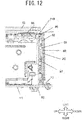
- FIG. 12 is a cross-sectional view of the line XII-XII of FIG. 10B .
- the vibration damping material 83 is formed of an elastic material, such as ethylene-propylene-diene rubber (EPDM), for example.
- EPDM ethylene-propylene-diene rubber
- the vibration damping material 83 has a substantially rectangular shape in which the length thereof (the length in the front-rear direction) is substantially the same as the entire length of the high-voltage harness 65 extending above the electricity storage modules 40A to 40C, and the width thereof (the length in the left-right direction) covers a region from the high-voltage harness 65 to the high-voltage harness 62.
- the vibration damping material 83 is bonded to the bottom cover 13, and biases the high-voltage harnesses 62 and 65 toward the side of the lower surface parts 113 of the holding cases 111 of the electricity storage modules 40A and 40B with the bottom cover 13 fixed to the main case 11.
- the vibration of the high-voltage harnesses 62 and 65 is suppressed.
- the harness holders 70A to 70C are formed of an insulating member, such as resin.
- the harness holders 70A and 70B have the same structure, and have fixing side parts 71A and 71B, fixing lower parts 77A and 77B, pairs of supporting parts 72A and 72B, connecting parts (pressing parts) 73A and 73B which connect the pairs of supporting parts 72A and 72B, and guiding parts 78A and 78B, respectively.
- a plurality of (two in the present embodiment) openings (first engaging parts) 74A and 74B are respectively provided in the fixing side parts 71A and 71B.
- Step parts 76Aa and 76Ba are respectively formed at the boundaries between the connecting parts 73A and 73B and the pairs of supporting parts 72A and 72B, and the connecting parts 73A and 73B are arranged at a position lower than the supporting parts 72A and 72B and the guiding parts 78A and 78B by steps of the step parts 76Aa and 76Ba, respectively.
- Restricting walls 76Ab and 76Bb are formed at the boundaries between the connecting parts 73A and 73B and the guiding parts 78A and 78B, respectively.
- Protruding pieces (second engaging parts) 75A and 75B which protrude to the up direction are provided on the fixing lower parts 77A and 77B.
- the restricting walls 76Ab and 76Bb and the protruding pieces 75A and 75B have a function as movement restricting parts that restrict the movement of the high-voltage harness 65 in a direction perpendicular to the extending direction.
- the pairs of supporting parts 72A and 72B, the connecting parts 73A and 73B, and the guiding parts 78A and 78B of the harness holders 70A and 70B are formed to extend in a direction substantially perpendicular to the fixing side parts 71A and 71B.
- the pairs of supporting parts 72A and 72B are formed to be thin, and can be displaced in the up-down direction with respect to the fixing side parts 71A and 71B, respectively.
- the pairs of supporting parts 72A and 72B, the connecting parts 73A and 73B, and the guiding parts 78A and 78B are displaced upward, in other words, toward the side of the electricity storage modules 40A and 40B, by the vibration damping material 83 bonded to the bottom cover 13.
- the connecting parts 73A and 73B biases the high-voltage harness 65 toward the electricity storage modules 40A and 40B such that the high-voltage harness 65 can be displaced in the left-right direction.
- the harness holder 70C has a fixing side part 71C and a fixing lower part 77C.
- a protruding piece 75C is provided to the tip point of the fixing lower part 77C.
- the fixing lower part 77C extends in a direction substantially perpendicular to the fixing side part 71C.
- a projection (second locking part) 111c is provided on the lower surface part 113 of the holding case 111 of each of the electricity storage modules 40A to 40C.
- the harness holders 70A and 70B fit the openings 74A and 74B of the fixing side parts 71A and 71B with the protrusions 111b of the tubular parts 111a of the electricity storage modules 40A and 40B, respectively.
- the harness holders 70A and 70B engage the protruding pieces (second engaging parts) 75A and 75B of the fixing lower parts 77A and 77B with the projections 111c of the electricity storage modules 40A and 40B, respectively.
- the harness holders 70A and 70B are fixed to the electricity storage modules 40A and 40B, respectively, without using a fastening member.
- respective connecting parts 73A and 73B of the harness holders 70A and 70B are arranged between the tubular parts 111a of the holding cases 111 of the electricity storage modules 40A and 40B, and bias the high-voltage harness 65 toward the side of the lower surface parts 113 of the electricity storage modules 40A and 40B.
- the high-voltage harness 65 biased toward a side of the electricity storage modules 40A and 40B by the harness holders 70A and 70B can be displaced in the left-right direction, in other words, in the direction perpendicular to the extending direction of the high-voltage harness 65 between the restricting walls 76Ab and 76Bb and the protruding pieces 75A and 75B of the harness holders 70A and 70B. Accordingly, even when the length of the high-voltage harness 65 varies by the tolerance, the high-voltage harness 65 is surely biased toward the electricity storage modules 40A and 40B by the harness holders 70A and 70B. This will be described.
- the high-voltage harness 65 is formed to have a large thickness for lowering the resistance, and has high rigidity.
- the high-voltage harness 65 is formed to have a length with a margin with respect to the length between connecting terminals to be connected. Therefore, the high-voltage harness 65 is disposed on the electricity storage modules 40A and 40B to curve in the left-right direction, in other words, in the direction perpendicular to the extending direction of the high-voltage harness 65.
- the length of the high-voltage harness 65 varies by the tolerance.
- the variation in the length of the high-voltage harness 65 can be absorbed by displacing the high-voltage harness 65 disposed on the electricity storage modules 40A and 40B in the left-right direction to change the degree of curvature.
- the distance between the restricting walls 76Ab and 76Bb and the protruding pieces 75A and 75B of the harness holders 70A and 70B in the left-right direction is larger than the thickness of the high-voltage harness 65, and the high-voltage harness 65 can be displaced in the left-right direction.
- the harness holders 70A and 70B have a structure in which the high-voltage harness 65 can be surely biased toward the side of the electricity storage modules 40A and 40B even when there is a variation in the length of the high-voltage harness 65 in the extending direction.
- Fixing of the harness holder 70C is the same as that when the harness holders 70A and 70B are fixed to the electricity storage modules 40A and 40B, and the harness holder 70C does not include a supporting part, a connecting part, a guiding part, a step part, and a restricting wall.
- the temperature sensor lines 87 are inserted into the guiding parts 78A and 78B of the harness holders 70A and 70B (refer to FIG. 9 ).
- the voltage detection lines 86 are inserted into a guiding part 79 of the harness holders 70A to 70C (refer to FIG. 9 ).
- the high-voltage harness 65 is disposed on the lower surface parts 113 of the holding cases 111 of the electricity storage modules 40A to 40C.
- the harness holders 70A to 70C are fixed to the electricity storage modules 40A to 40C, respectively, by the above-described procedure.
- the high-voltage harness 65 is displaced as necessary such that the high-voltage harness 65 is arranged between the restricting walls 76Ab and 76Bb and the protruding pieces 75A and 75B of the harness holders 70A and 70B.
- the vibration damping material 83 is bonded to the inner surface of the bottom cover 13 in advance, and the bottom cover 13 is fixed to the main case 11 with fastening members, such as bolts.
- the high-voltage harnesses 62 and 65 are biased toward the side of the lower surface parts 113 of the holding cases 111 of the electricity storage modules 40A and 40B directly or through the harness holders 70A and 70B by the vibration damping material 83.
- the present invention solves a new problem, that is, a reduction in noise by the generation of the vibrating sound from the electricity storage device, which is due to the vibration of the high-voltage harnesses during charging/discharging.
- the vibrating sound suppression structure by the vibration damping material 83 is illustrated by the structure that takes measures against the high-voltage harnesses 62 and 65.
- the vibrating sound suppression structure may be applied to only the high-voltage harness 65 whose extending length is the longest, and thus, whose tolerance is the largest.
- the structure in which the linear energy of the high-voltage harnesses 62 and 65 is changed to the planar energy by the harness holders 70A to 70C fixed to the electricity storage modules 40A to 40C is illustrated.
- a sheet-shaped energy diffusion member which is wider than the thicknesses of the high-voltage harnesses 62 and 65 may be interposed between the high-voltage harnesses 62 and 65 and the vibration damping material 83.
- the sheet-shaped energy diffusion member may be bonded to one of the high-voltage harnesses 62 and 65 and the vibration damping material 83.
- the structure in which the high-voltage harness 65 can be displaced in the direction perpendicular to the extending direction of the high-voltage harness 65 between the restricting walls 76Ab and 76Bb and the protruding pieces 75A and 75B of the harness holders 70A and 70B so that the variation in the length of the high-voltage harness 65 is absorbed is illustrated.
- a clamping member may be provided in front of the electricity storage module 40A in the electricity storage module-housing area 2A such that the variation of the high-voltage harness 65 is absorbed by holding the high-voltage harness 65 with the clamping member.
- the distance between the restricting walls 76Ab and 76Bb and the protruding pieces 75A and 75B of the harness holders 70A and 70B may be made to be substantially the same as the thickness of the high-voltage harness 65 such that the high-voltage harness 65 may not be displaced in the direction perpendicular to the extending direction.
- a clamper may be used in place of the harness holders 70A and 70B such that the high-voltage harness 65 is fixed with the clamper.
- the structure in which the openings 74A to 74C of the fixing side parts 71A to 71C of the harness holders 70A to 70C are fitted with the disk-shaped protrusions 111b which are end parts of the tubular parts 111a of the holding cases 111 of the electricity storage modules 40A to 40C is illustrated.
- other disk-shaped protrusions may be provided on the holding cases 111 such that the openings 74A to 74C of the fixing side parts 71A to 71C of the harness holders 70A to 70C are fitted with the protrusions.
- the harness holders 70A to 70C may be fixed to the electricity storage modules 40A to 40C using a fastening member.
- the present invention is not limited to the electricity storage device including a lithium-ion secondary battery, and can also be applied to an electricity storage device including a secondary battery using an aqueous electrolyte, such as a nickel-hydride battery, a nickel-cadmium battery, or a lead storage battery.
- an electricity storage device including an electricity storage element such as a lithium-ion capacitor or an electrolytic double-layer capacitor.
- the electricity storage device of the present invention can be applied by making various modifications within the scope of the gist of the invention, and the point is that the electricity storage device includes a plurality of electricity storage modules, each including an electricity storage module case and a plurality of electricity storage cells housed in the electricity storage module case, and each having external terminals of positive and negative electrodes; an electricity storage case in which the plurality of electricity storage modules are linearly arranged and housed; a plurality of wire harnesses connected to the external terminals of the positive and negative electrodes of the electricity storage modules; and a vibration damping material provided in a space region between one surface of the electricity storage case and, among the plurality of wire harnesses, at least a wire harness having the longest length extending in an arrangement direction of the electricity storage modules, in which at least a part of the wire harness having the longest length extending in the arrangement direction of the electricity storage modules is biased toward the side of the electricity storage module case by the one surface of the electricity storage case, through the vibration damping material.
Abstract
Description
- The present invention relates to an electricity storage device in which a plurality of electricity storage modules are housed.
- An electricity storage device, as a power source, is mounted on electric vehicles, hybrid vehicles, and the like. In a case of the electricity storage device, a plurality of electricity storage modules, each including a plurality of secondary battery cells, such as lithium-ion secondary battery cells, are arranged and housed.
- The electricity storage modules are electrically connected via wire harnesses connected to external terminals. A large current flows in the wire harnesses when charging/discharging the electricity storage device, and thus, the wire harnesses are members having large thicknesses and small resistances.
- Conventionally, a power-supply device in which a plurality of holder cases, each housing a predetermined plurality number of electricity storage modules, are housed in an outer case is known. The power-supply device has a structure in which concave parts are provided on the respective holder cases and a power-supply line formed of a metal plate is fit into the concave parts. By the structure, even when the power-supply device is shaken by vibration or the like during running of a vehicle, breakage of connecting terminals due to vibration of the power-supply line is prevented (for example, refer to PTL 1).
- PTL 1:
JP 2001-6643 A - In recent years, a sense of discomfort provided by vibrating sound generated when the wire harnesses vibrate to come into contact with a case member of the electricity storage device when charging/discharging the electricity storage device has become a problem. The above-described patent literature does not take measures against the problem. In addition, a vibration prevention structure of the wire harnesses connected to the respective electricity storage modules in the holder cases is not provided.
- According to one aspect of the present invention, there is provided an electricity storage device including: a plurality of electricity storage modules, each including an electricity storage module case, a plurality of electricity storage cells housed in the electricity storage module case, and external terminals of positive and negative electrodes; an electricity storage case in which the plurality of electricity storage modules are arranged and housed; a plurality of wire harnesses connected to the external terminals of the positive and negative electrodes of the electricity storage modules; and a vibration damping material provided in a space region between one surface of the electricity storage case and, among the plurality of wire harnesses, at least a wire harness including the longest length extending in an arrangement direction of the electricity storage modules, wherein the wire harness including the longest length extending in the arrangement direction of the electricity storage modules is biased toward a side of the electricity storage module case by the one surface of the electricity storage case, through the vibration damping material.
- According to the present invention, vibrating sound generated when the wire harnesses vibrate to come into contact with a case member of the electricity storage device when charging/discharging the electricity storage device can be suppressed.
-
-
FIG. 1 is an external perspective view of an embodiment of an electricity storage device according to the present invention; -
FIG. 2 is an exploded perspective view of the electricity storage device illustrated inFIG. 1 ; -
FIG. 3 is a perspective view of an electricity storage module illustrated inFIG. 2 ; -
FIG. 4 is a schematic external perspective view of the electricity storage module illustrated inFIG. 3 ; -
FIG. 5A is an exploded perspective view for describing the structure of the electricity storage module illustrated inFIG. 3 ; -
FIG. 5B is a schematic external perspective view of the electricity storage module; -
FIG. 6A is a perspective view for describing the electrical connection state of each of the electricity storage modules; -
FIG. 6B is a bottom view ofFIG. 6A ; -
FIG. 7 is a schematic side view for describing the electrical connection state of each of the electricity storage modules; -
FIG. 8 is a schematic view for describing the connection state of voltage detection lines to each of the electricity storage modules; -
FIG. 9 is an enlarged perspective view illustrating the holding structure of harnesses by harness holders; -
FIG. 10A is a side view illustrating the positional relationship between each of the electricity storage modules and a bottom cover and a top cover of an electricity storage case; -
FIG. 10B is a bottom view ofFIG. 10A ; -
FIG. 11 is a cross-sectional view taken along the line XI-XI ofFIG. 10B ; and -
FIG. 12 is a cross-sectional view taken along the line XII-XII ofFIG. 10B . - Hereinafter, an embodiment of an electricity storage device of the present invention will be described with reference to the drawings.
- The electricity storage device according to the present embodiment is applied to an in-vehicle power-supply device in a motor drive system of a motor-driven vehicle, for example, an electric vehicle. The concept of the electric vehicle includes a hybrid electric vehicle including an engine that is an internal-combustion engine, and a motor, as a driving source of the vehicle, and a pure electric vehicle using a motor as a sole driving source of the vehicle, and the like.
-
FIG. 1 is an external perspective view of the embodiment of the electricity storage device according to the present invention, andFIG. 2 is an exploded perspective view of the electricity storage device illustrated inFIG. 1 . Anelectricity storage device 1 is, for example, a lithium-ion battery device, and a plurality ofelectricity storage modules 40A to 40C, each including a plurality of secondary battery cells (electricity storage cells) 101, such as lithium-ion secondary battery cells, (refer toFIGs. 5A and 5B ) is housed in anelectricity storage case 2 that is a housing of theelectricity storage device 1. Theelectricity storage case 2 has a shape in which a small rectangular parallelepiped is connected to the front side of a large rectangular parallelepiped. In the following description, a front-rear direction, a left-right direction, and an up-down direction will be described as directions illustrated inFIG. 1 andFIG. 2 . Each direction illustrated inFIG. 1 andFIG. 2 corresponds to the front-rear direction, the left-right direction, and the up-down direction in a vehicle on which theelectricity storage device 1 is mounted, respectively. - The
electricity storage case 2 includes amain case 11, aside cover 12, abottom cover 13, and atop cover 14. Themain case 11 is a member having a frame shape in which the upper part, the lower part, and the left part open. Each of themain case 11, theside cover 12, thebottom cover 13, and thetop cover 14 is formed by pressing a metal thin plate, for example. - The
side cover 12 is a member arranged to be opposed to aright wall 11a of themain case 11, constitutes a left wall, and closes the opening of the left part of themain case 11. Throughholes 12a into whichbolts 81 to be described below, which are through bolts, are to be inserted are provided in theside cover 12. Thebottom cover 13 is a member that closes the opening of the lower part of themain case 11, and thetop cover 14 is a member that closes the opening of the upper part of themain case 11. Each of theside cover 12, thebottom cover 13, and thetop cover 14 is fixed to themain case 11 with fastening members, such as bolts, to form a space for housing electronic components therein. - In the
electricity storage case 2, an electricity storage module-housing area 2A in which theelectricity storage modules 40A to 40C are to be housed, and a control unit-housing area 2B in which ajunction box 3 is to be housed are formed. Thejunction box 3 is a control circuit that measures a charge/discharge current, outputs a signal, and has a precharge function to suppress an inrush current into a capacitor of an inverter when activating a vehicle. - In the electricity storage module-
housing area 2A, a plurality of (three in the present embodiment)electricity storage modules 40A to 40C are arranged. Each of theelectricity storage modules 40A to 40C has a block shape of a rectangular parallelepiped. In the present embodiment, each of theelectricity storage modules 40A to 40C is housed to be arranged adjacent to and in parallel with one another in the front-rear direction with the longitudinal directions thereof extending in the up-down direction in themain case 11. Each of theelectricity storage modules 40A to 40C is arranged linearly at predetermined intervals in order of theelectricity storage modules housing area 2B, i.e., to the rear direction. Hereinafter, theelectricity storage modules 40A to 40C will be collectively described as anelectricity storage module 40, appropriately. As will be described below, theelectricity storage module 40 is fixed to themain case 11 with thebolts 81 together with theside cover 12. Back nuts 82 to be fastened to the bolts 81 (refer toFIG. 10B ) are welded to be fixed to the right-side surface of theright wall 11a of themain case 11. - A lithium-ion battery controller (hereinafter, LBC) 4 is disposed above the control unit-
housing area 2B. TheLBC 4 is a control circuit for measuring, monitoring, and controlling a voltage, a current, a temperature, charge/discharge, and the like for theelectricity storage module 40 and each cell, and is covered with aLBC cover 15. - The electricity storage module-
housing area 2A and the control unit-housing area 2B of theelectricity storage case 2 are partitioned by a partitioningmember 80. In addition, as illustrated inFIG. 1 , a SD (service disconnect) switch 53 is inserted into an opening of thetop cover 14 to project outward from thetop cover 14 of theelectricity storage case 2. -
FIG. 3 is a perspective view of the electricity storage module illustrated inFIG. 2 , andFIG. 4 is a schematic external perspective view of the electricity storage module illustrated inFIG. 3 . In addition,FIG. 5A is an exploded perspective view for describing the structure of the electricity storage module illustrated inFIG. 3 , andFIG. 5B is a schematic external perspective view of the electricity storage module. Arefrigerant inlet port 116 is provided on the left part of each of theelectricity storage modules 40A to 40C. In addition, arefrigerant outlet port 118 is provided on the right part of each of theelectricity storage modules 40A to 40C. In the respectiveelectricity storage modules 40A to 40C, positive electrode terminals (external terminals) 41A to 41C and negative electrode terminals (external terminals) 42A to 42C are provided on separated parts on both ends in the longitudinal (up-down) direction, as illustrated in the schematic view ofFIG. 4 . Each of theelectricity storage modules 40A to 40C has a rectangular parallelepiped-shapedholding case 111, and cylindricaltubular parts 111a (tubular protrusions) extending in the left-right direction are integrally formed on four corners of the holdingcase 111. In each of thetubular parts 111a, a module fixing through hole (insertion part) 43 that penetrates each of thetubular parts 111a in the axial direction is respectively provided. The above-describedbolts 81 are inserted into the throughholes 12a of theside cover 12 and the module fixing throughholes 43 of thetubular parts 111a of theelectricity storage module 40 to be screwed into theback nuts 82 welded on the rear surface of themain case 11. -
FIG. 6A is a perspective view for describing the electrical connection state of each of the electricity storage modules, andFIG. 6B is a bottom view ofFIG. 6A . In addition,FIG. 7 is a schematic side view for describing the connection state of high-voltage harnesses 61 to 65 to each of theelectricity storage modules 40A to 40C. - The high-voltage harnesses (wire harnesses) 61 to 65 are connected to the six external terminals, the
positive electrode terminal 41A of theelectricity storage module 40A to thenegative electrode terminal 42C of theelectricity storage module 40C, and thus, theelectricity storage modules 40A to 40C are connected in series. More specifically, aplus terminal 3a of thejunction box 3 and thepositive electrode terminal 41A of theelectricity storage module 40A are connected with the high-voltage harness 61, and thenegative electrode terminal 42A of theelectricity storage module 40A and thepositive electrode terminal 41B of theelectricity storage module 40B are connected with the high-voltage harness 62. - The
negative electrode terminal 42B of theelectricity storage module 40B and thepositive electrode terminal 41C of theelectricity storage module 40C are connected through the high-voltage harness 63, theSD switch 53, and the high-voltage harness 64. Thenegative electrode terminal 42C of theelectricity storage module 40C and aminus terminal 3b of thejunction box 3 are connected with the high-voltage harness 65. - The
SD switch 53 is a safety device provided to ensure safety during maintenance and inspection of theelectricity storage device 1, includes an electric circuit in which a switch and a fuse are electrically connected in series, and is operated by service personnel at the time of maintenance and inspection. In the present embodiment, as described above, theSD switch 53 is provided between thenegative electrode terminal 42B of theelectricity storage module 40B and thepositive electrode terminal 41C of theelectricity storage module 40C, and electrically connects or disconnects between theelectricity storage module 40B and theelectricity storage module 40C. The above-described connection between the high-voltage harnesses 61 to 65 and theelectricity storage modules 40A to 40C is preferably jointing by soldering or the like, and the connection between the high-voltage harnesses 61 to 65 and thejunction box 3 or theSD switch 53 is preferably a connection by a connector. However, both may be jointing by soldering or the like, or a connection by a connector. - The
electricity storage module 40C is formed such that the number of thesecondary battery cells 101 housed therein is smaller than those of theelectricity storage modules electricity storage modules electricity storage module 40B arranged at the center in the arrangement direction is reversely arranged with respect to theelectricity storage modules negative electrode terminal 42A of theelectricity storage module 40A and thepositive electrode terminal 41B of theelectricity storage module 40B are arranged in the down direction, and can be connected with the high-voltage harness 62 having a short length. -
FIG. 8 is a schematic view for describing the connection state ofvoltage detection lines 86 to each of theelectricity storage modules 40A to 40C. Each of theelectricity storage modules 40A to 40C has twovoltage detection substrates voltage detection lines 86 connect theLBC 4 toconnector connection parts 201a of the respectivevoltage detection substrates 201 andconnector connection parts 202a of the respectivevoltage detection substrates 202. - In addition, the
electricity storage modules 40A to 40C have temperature detection sensors for detecting temperatures of theelectricity storage modules 40A to 40C, which are not illustrated. TheLBC 4 and each of the temperature detection sensors are connected with atemperature sensor line 87. - The
electricity storage modules 40A to 40C have the same structure. As illustrated inFIG. 5A , theelectricity storage module 40 has a structure in which the plurality ofsecondary battery cells 101 is held in an electricity storage module case, i.e., the holdingcase 111, and, in the present embodiment, as will be described below, thesecondary battery cells 101 are arranged in three steps in the left-right direction. As illustrated inFIG. 5B , the holdingcase 111 has a hexahedron shape. The holdingcase 111 has anupper surface part 112 and alower surface part 113 which are spaced apart from and opposed to each other in the up-down direction, and a pair ofvertical wall parts 114 which is spaced apart from and opposed to each other in the front-rear direction and extends over each of short side parts of theupper surface part 112 and thelower surface part 113. In addition, the holdingcase 111 is formed of resin, for example, and has a pair of a left-end surface part 115a and a right-end surface part 115b which is spaced apart from and opposed to each other in the left-right direction and extends over each of long side parts of theupper surface part 112, thelower surface part 113, and the pair ofvertical wall parts 114. - The above-described
refrigerant inlet port 116 is formed on the left-end surface part 115a of the holdingcase 111. The above-describedrefrigerant outlet port 118 is formed on the right-end surface part 115b of the holdingcase 111.FIG. 5B is a schematic view for illustrating the positional relationship between therefrigerant inlet port 116 and therefrigerant outlet port 118. A refrigerant, such as air, flows into the holdingcase 111 from therefrigerant inlet port 116, flows in the holdingcase 111 in the left-right direction, and flows out from therefrigerant outlet port 118 on the right side. - The
electricity storage module 40 is arranged in a state of being housed in theelectricity storage case 2 such that the left-end surface part 115a of the holdingcase 111 is opposed to the side cover 12 (also refer toFIG. 2 ), and therefrigerant inlet port 116 of the left-end surface part 115a is opposed to an intake port of theside cover 12, which is not illustrated. In addition, the right-end surface part 115b of the holdingcase 111 of theelectricity storage module 40 is arranged to be opposed to theright wall 11a of themain case 11, and therefrigerant outlet port 118 of the right-end surface part 115b is opposed to anexhaust port 11b of theright wall 11a (refer toFIG. 2 ). - As described above, the high-
voltage harness 61 connects thepositive electrode terminal 41A on the upper side of theelectricity storage module 40A to thejunction box 3. The high-voltage harnesses 63 and 64 respectively connect thenegative electrode terminal 42B on the upper side of theelectricity storage module 40B and thepositive electrode terminal 41C on the upper side of theelectricity storage module 40C to theSD switch 53 arranged above theelectricity storage module 40. - On the other hand, as illustrated in
FIG. 6A , the high-voltage harnesses 62 and 65 are disposed on the lower-surface side of theelectricity storage modules 40A to 40C. The high-voltage harness 62 extends in the arrangement direction (front-rear direction) of theelectricity storage modules 40A to 40C, and connects thenegative electrode terminal 42A of theelectricity storage module 40A and thepositive electrode terminal 41B of theelectricity storage module 40B, which are next to each other. The high-voltage harness 65 connects theelectricity storage module 40C arranged farthest from thejunction box 3 in the front-rear direction, among theelectricity storage modules 40A to 40C, and thejunction box 3. Thus, the high-voltage harness 65 is placed below theelectricity storage modules 40A to 40C from thenegative electrode terminal 42C that is an external terminal on the negative-electrode side to the side surface of theelectricity storage module 40A on the side of thejunction box 3, and extends in the arrangement direction (front-rear direction) of theelectricity storage modules 40A to 40C. - The high-voltage harnesses 62 and 65 are loosely disposed in order to facilitate easy connecting and due to variation in lengths. Thus, when charging/discharging the
electricity storage device 1, the high-voltage harnesses 62 and 65 vibrate to come into contact with thebottom cover 13 of theelectricity storage case 2, thereby generating vibrating sound. - In
FIG. 2 ,harness holders 70A to 70C and avibration damping material 83 are disposed in aspace region 2C between thebottom cover 13 and theelectricity storage modules 40A to 40C (refer toFIGs. 11 and12 ). Theharness holders 70A to 70C and thevibration damping material 83 configure a harness vibrating sound prevention structure during charging/discharging, which suppresses the generation of the vibrating sound by the high-voltage harnesses 62 and 65. - Hereinafter, this will be described.
-
FIG. 9 is an enlarged perspective view illustrating the holding structure of the harnesses by the harness holders.FIG. 10A is a side view illustrating the positional relationship between each of the electricity storage modules and the bottom cover and the top cover of the electricity storage case, andFIG. 10B is a bottom view ofFIG. 10A . In addition,FIG. 11 is a cross-sectional view of the line XI-XI ofFIG. 10B , andFIG. 12 is a cross-sectional view of the line XII-XII ofFIG. 10B . - The
vibration damping material 83 is formed of an elastic material, such as ethylene-propylene-diene rubber (EPDM), for example. Thevibration damping material 83 has a substantially rectangular shape in which the length thereof (the length in the front-rear direction) is substantially the same as the entire length of the high-voltage harness 65 extending above theelectricity storage modules 40A to 40C, and the width thereof (the length in the left-right direction) covers a region from the high-voltage harness 65 to the high-voltage harness 62. Thevibration damping material 83 is bonded to thebottom cover 13, and biases the high-voltage harnesses 62 and 65 toward the side of thelower surface parts 113 of the holdingcases 111 of theelectricity storage modules bottom cover 13 fixed to themain case 11. Thus, when charging/discharging theelectricity storage device 1, the vibration of the high-voltage harnesses 62 and 65 is suppressed. - The
harness holders 70A to 70C are formed of an insulating member, such as resin. Theharness holders side parts lower parts parts parts parts side parts parts parts parts parts parts parts parts FIGs. 9 and11 ) are provided on the fixinglower parts pieces voltage harness 65 in a direction perpendicular to the extending direction. - The pairs of supporting
parts parts parts harness holders side parts parts side parts parts parts parts electricity storage modules vibration damping material 83 bonded to thebottom cover 13. In this state, the connectingparts voltage harness 65 toward theelectricity storage modules voltage harness 65 can be displaced in the left-right direction. The details will be described below. - The
harness holder 70C has a fixingside part 71C and a fixinglower part 77C. A protrudingpiece 75C is provided to the tip point of the fixinglower part 77C. The fixinglower part 77C extends in a direction substantially perpendicular to the fixingside part 71C. - End parts of the
tubular parts 111a of the holdingcase 111 of each of theelectricity storage modules 40A to 40C in the axial direction (left-right direction) protrude a little from the outer surface of the left-end surface part 115a to form circular protrusions (first locking parts) 111b (refer toFIGs. 6A and 6B ). In addition, a projection (second locking part) 111c (refer toFIGs. 6B and11 ) is provided on thelower surface part 113 of the holdingcase 111 of each of theelectricity storage modules 40A to 40C. - The
harness holders openings side parts protrusions 111b of thetubular parts 111a of theelectricity storage modules harness holders lower parts projections 111c of theelectricity storage modules harness holders electricity storage modules parts harness holders tubular parts 111a of the holdingcases 111 of theelectricity storage modules voltage harness 65 toward the side of thelower surface parts 113 of theelectricity storage modules voltage harness 65 biased toward a side of theelectricity storage modules harness holders voltage harness 65 between the restricting walls 76Ab and 76Bb and the protrudingpieces harness holders voltage harness 65 varies by the tolerance, the high-voltage harness 65 is surely biased toward theelectricity storage modules harness holders - The high-
voltage harness 65 is formed to have a large thickness for lowering the resistance, and has high rigidity. In order to make it easy to dispose the high-voltage harness 65 and to be joined to the external terminal, the high-voltage harness 65 is formed to have a length with a margin with respect to the length between connecting terminals to be connected. Therefore, the high-voltage harness 65 is disposed on theelectricity storage modules voltage harness 65. Here, the length of the high-voltage harness 65 varies by the tolerance. The variation in the length of the high-voltage harness 65 can be absorbed by displacing the high-voltage harness 65 disposed on theelectricity storage modules pieces harness holders voltage harness 65, and the high-voltage harness 65 can be displaced in the left-right direction. As just described, in the embodiment of the present invention, theharness holders voltage harness 65 can be surely biased toward the side of theelectricity storage modules voltage harness 65 in the extending direction. - Fixing of the
harness holder 70C is the same as that when theharness holders electricity storage modules harness holder 70C does not include a supporting part, a connecting part, a guiding part, a step part, and a restricting wall. - The
temperature sensor lines 87 are inserted into the guidingparts harness holders FIG. 9 ). In addition, thevoltage detection lines 86 are inserted into a guidingpart 79 of theharness holders 70A to 70C (refer toFIG. 9 ). - One example of an assembling method of the harness vibrating sound prevention structure will be described.
- It is assumed that the high-voltage harnesses 61 to 65 are electrically joined to predetermined connecting terminals.
- The high-
voltage harness 65 is disposed on thelower surface parts 113 of the holdingcases 111 of theelectricity storage modules 40A to 40C. Theharness holders 70A to 70C are fixed to theelectricity storage modules 40A to 40C, respectively, by the above-described procedure. When theharness holders voltage harness 65 is displaced as necessary such that the high-voltage harness 65 is arranged between the restricting walls 76Ab and 76Bb and the protrudingpieces harness holders vibration damping material 83 is bonded to the inner surface of thebottom cover 13 in advance, and thebottom cover 13 is fixed to themain case 11 with fastening members, such as bolts. - Accordingly, the high-voltage harnesses 62 and 65 are biased toward the side of the
lower surface parts 113 of the holdingcases 111 of theelectricity storage modules harness holders vibration damping material 83. - The background of the present invention will be supplemented.
- In order to expand effective space in a vehicle, in recent years, installation space of electricity storage modules has been further reduced in size. As a result, space in which high-voltage harnesses are disposed is also reduced in size, and thus, generation of harsh vibrating sound from an electricity storage device is sometimes recognized.
- When the present inventors conducted an investigation into the cause, it was confirmed that this is because the high-voltage harnesses vibrate to come into contact with an electricity storage case by a charge/discharge current when charging/discharging the electricity storage modules. As just described, the present invention solves a new problem, that is, a reduction in noise by the generation of the vibrating sound from the electricity storage device, which is due to the vibration of the high-voltage harnesses during charging/discharging.
- The following advantageous effects are exhibited by the above-described embodiment of the
electricity storage device 1 of the present invention. - (1) The high-voltage harnesses 62 and 65 disposed in the
space region 2C between theelectricity storage modules 40A to 40C and theelectricity storage case 2 are configured to be biased toward the side of theelectricity storage modules 40A to 40C by thevibration damping material 83. Thus, the vibration of the high-voltage harnesses 62 and 65 generated when charging/discharging theelectricity storage device 1 is alleviated, and the generation of the vibrating sound due to the contact with theelectricity storage case 2 or theelectricity storage modules 40A to 40C can be suppressed. - (2) The
harness holders harness holders vibration damping material 83, and thus, the vibration absorption efficiency can be increased. - (3) The distance between the restricting walls 76Ab and 76Bb and the protruding
pieces harness holders voltage harness 65, and the high-voltage harness 65 can be displaced in the direction perpendicular to the extending direction thereof. Thus, the high-voltage harness 65 can be surely biased toward the side of theelectricity storage modules harness holders voltage harness 65 in the extending direction. - (4) The
openings 74A to 74C of the fixingside parts 71A to 71C and the protrudingpieces 75A to 75C of theharness holders 70A to 70C are engaged with theprotrusions 111b and theprojections 111c of theelectricity storage modules 40A to 40C, respectively, so that theharness holders 70A to 70C are fixed to theelectricity storage modules 40A to 40C only by the engagement, without using a fastening member or the like. In the fixing structure by the engaging mechanism, theharness holders 70A to 70C are loosened by looseness due to the engagement, thus a fixing posture is changed in association with the disposing configuration of the high-voltage harness having high rigidity, and the degree of freedom of fixing of the high-voltage harness can be increased. - (5) The
harness holders side parts parts parts parts harness holders 70A to 70C are fixed to theelectricity storage modules harness holders voltage harness 65. Accordingly, the alleviation efficiency of the vibration of the high-voltage harness 65 can be improved. - In the above-described embodiment, the vibrating sound suppression structure by the
vibration damping material 83 is illustrated by the structure that takes measures against the high-voltage harnesses 62 and 65. However, among the high-voltage harnesses 62 and 65 disposed on theelectricity storage modules 40A to 40C, the vibrating sound suppression structure may be applied to only the high-voltage harness 65 whose extending length is the longest, and thus, whose tolerance is the largest. - In the above-described embodiment, the structure in which the linear energy of the high-voltage harnesses 62 and 65 is changed to the planar energy by the
harness holders 70A to 70C fixed to theelectricity storage modules 40A to 40C is illustrated. However, in place of theharness holders 70A to 70C, a sheet-shaped energy diffusion member which is wider than the thicknesses of the high-voltage harnesses 62 and 65 may be interposed between the high-voltage harnesses 62 and 65 and thevibration damping material 83. The sheet-shaped energy diffusion member may be bonded to one of the high-voltage harnesses 62 and 65 and thevibration damping material 83. - In the above-described embodiment, the structure in which the high-
voltage harness 65 can be displaced in the direction perpendicular to the extending direction of the high-voltage harness 65 between the restricting walls 76Ab and 76Bb and the protrudingpieces harness holders voltage harness 65 is absorbed is illustrated. However, a clamping member may be provided in front of theelectricity storage module 40A in the electricity storage module-housing area 2A such that the variation of the high-voltage harness 65 is absorbed by holding the high-voltage harness 65 with the clamping member. In the case of the foregoing structure, the distance between the restricting walls 76Ab and 76Bb and the protrudingpieces harness holders voltage harness 65 such that the high-voltage harness 65 may not be displaced in the direction perpendicular to the extending direction. In addition, a clamper may be used in place of theharness holders voltage harness 65 is fixed with the clamper. - In the above-described embodiment, the structure in which the
harness holders voltage harness 65 is illustrated, but another vibration damping material may be interposed between theharness holders voltage harness 65. - In the above-described embodiment, the structure in which the
openings 74A to 74C of the fixingside parts 71A to 71C of theharness holders 70A to 70C are fitted with the disk-shapedprotrusions 111b which are end parts of thetubular parts 111a of the holdingcases 111 of theelectricity storage modules 40A to 40C is illustrated. However, other disk-shaped protrusions may be provided on the holdingcases 111 such that theopenings 74A to 74C of the fixingside parts 71A to 71C of theharness holders 70A to 70C are fitted with the protrusions. - The
harness holders 70A to 70C may be fixed to theelectricity storage modules 40A to 40C using a fastening member. - Various modes can be applied to the structure of the
electricity storage case 2. - The present invention is not limited to the electricity storage device including a lithium-ion secondary battery, and can also be applied to an electricity storage device including a secondary battery using an aqueous electrolyte, such as a nickel-hydride battery, a nickel-cadmium battery, or a lead storage battery. In addition, the present invention can also be applied to an electricity storage device including an electricity storage element, such as a lithium-ion capacitor or an electrolytic double-layer capacitor.
- In addition, the electricity storage device of the present invention can be applied by making various modifications within the scope of the gist of the invention, and the point is that the electricity storage device includes a plurality of electricity storage modules, each including an electricity storage module case and a plurality of electricity storage cells housed in the electricity storage module case, and each having external terminals of positive and negative electrodes; an electricity storage case in which the plurality of electricity storage modules are linearly arranged and housed; a plurality of wire harnesses connected to the external terminals of the positive and negative electrodes of the electricity storage modules; and a vibration damping material provided in a space region between one surface of the electricity storage case and, among the plurality of wire harnesses, at least a wire harness having the longest length extending in an arrangement direction of the electricity storage modules, in which at least a part of the wire harness having the longest length extending in the arrangement direction of the electricity storage modules is biased toward the side of the electricity storage module case by the one surface of the electricity storage case, through the vibration damping material.
- The content of the disclosure of the following priority application is incorporated herein by reference.
- Japanese Patent Application No.
2014-175588 (filed on August 29, 2014 -
- 1
- Electricity storage device
- 2
- Electricity storage case
- 2A
- Electricity storage module-housing area
- 2B
- Control unit-housing area
- 2C
- Space region
- 3
- Junction box
- 3a
- Plus terminal
- 3c
- Minus terminal
- 4
- LBC
- 11
- Main case
- 11a
- Right wall
- 11b
- Exhaust port
- 12
- Side cover
- 12a
- Through hole
- 13
- Bottom cover
- 14
- Top cover
- 15
- LBC cover
- 40, 40A to 40C
- Electricity storage module
- 41A to 41C
- Positive electrode terminal (external terminal)
- 42A to 42C
- Negative electrode terminal (external terminal)
- 43
- Module fixing through hole (insertion part)
- 53
- SD switch
- 61 to 65
- High-voltage harness (wire harness)
- 70A to 70C
- Harness holder
- 71A to 71C
- Fixing side part
- 72A, 72B
- Supporting part
- 73A, 73B
- Connecting part (pressing part)
- 74A to 74C
- Opening (first engaging part)
- 75A to 75C
- Protruding piece (second engaging part)
- 76Aa, 76Ba
- Step part (movement restricting part)
- 76Ab, 76Bb
- Restricting wall (movement restricting part)
- 77A to 77C
- Fixing lower part
- 78A, 78B
- Guiding part
- 79
- Guiding part
- 80
- Partitioning member
- 81
- Bolt
- 82
- Back nut
- 83
- Vibration damping material
- 86
- Voltage detection line
- 87
- Temperature sensor line
- 101
- Secondary battery cell (electricity storage cell)
- 111
- Holding case (electricity storage module case)
- 111a
- Tubular part (tubular protrusion)
- 111b
- Protrusion (first locking part, disk-shaped protrusion)
- 111c
- Projection (second locking part)
- 112
- Upper surface part
- 113
- Lower surface part
- 114
- Vertical wall part
- 115a
- Left-end surface part
- 115b
- Right-end surface part
- 116
- Refrigerant inlet port
- 118
- Refrigerant outlet port
- 201, 202
- Voltage detection substrate
- 201a, 202a
- Connector connection part
Claims (8)
- An electricity storage device comprising:a plurality of electricity storage modules, each including an electricity storage module case, a plurality of electricity storage cells housed in the electricity storage module case, and external terminals of positive and negative electrodes;an electricity storage case in which the plurality of electricity storage modules are arranged and housed;a plurality of wire harnesses connected to the external terminals of the positive and negative electrodes of the electricity storage modules; anda vibration damping material provided in a space region between one surface of the electricity storage case and, among the plurality of wire harnesses, at least a wire harness including the longest length extending in an arrangement direction of the electricity storage modules, whereinthe wire harness including the longest length extending in the arrangement direction of the electricity storage modules is biased toward a side of the electricity storage module case by the one surface of the electricity storage case, through the vibration damping material.
- The electricity storage device according to claim 1, wherein
a vibration energy diffusion member that diffuses vibration energy of the wire harness and is wider than a thickness of the wire harness is provided in at least a part between the vibration damping material and the wire harness. - The electricity storage device according to claim 2, wherein
the vibration energy diffusion member is a harness holder including a pressing part that biases the wire harness toward the side of the electricity storage module case. - The electricity storage device according to claim 3, wherein
a movement restricting part that restricts movement of the wire harness in a direction perpendicular to an extending direction of the wire harness is provided on the harness holder. - The electricity storage device according to claim 4, wherein
the movement restricting part includes a pair of protrusions provided at an interval larger than the thickness of the wire harness, and
the wire harness can be displaced in the direction perpendicular to the extending direction of the wire harness. - The electricity storage device according to claim 3, wherein
tubular protrusions including insertion parts which extend in a direction substantially perpendicular to the extending direction of the wire harness and into which fastening members for fixing the electricity storage modules to the electricity storage case are to be inserted are provided on one surface of the electricity storage module case which is opposed to the one surface of the electricity storage case. - The electricity storage device according to claim 6, wherein
the harness holder includes the pressing part that biases the wire harness toward the side of the one surface of the electricity storage module case, and
the pressing part is arranged between the tubular protrusions of at least one of the electricity storage modules. - The electricity storage device according to any one of claims 1 to 7, wherein
the plurality of wire harnesses are arranged between the one surface of the electricity storage case and a plurality of the electricity storage module cases, and
the vibration damping material biases at least a part of each of the plurality of wire harnesses toward the side of at least one of the electricity storage module cases.
Applications Claiming Priority (2)
| Application Number | Priority Date | Filing Date | Title |
|---|---|---|---|
| JP2014175588 | 2014-08-29 | ||
| PCT/JP2015/074038 WO2016031863A1 (en) | 2014-08-29 | 2015-08-26 | Electricity storage device |
Publications (3)
| Publication Number | Publication Date |
|---|---|
| EP3188282A1 true EP3188282A1 (en) | 2017-07-05 |
| EP3188282A4 EP3188282A4 (en) | 2017-07-12 |
| EP3188282B1 EP3188282B1 (en) | 2018-11-14 |
Family
ID=55399749
Family Applications (1)
| Application Number | Title | Priority Date | Filing Date |
|---|---|---|---|
| EP15837025.4A Active EP3188282B1 (en) | 2014-08-29 | 2015-08-26 | Electricity storage device |
Country Status (8)
| Country | Link |
|---|---|
| US (1) | US10090495B2 (en) |
| EP (1) | EP3188282B1 (en) |
| JP (1) | JP6236537B2 (en) |
| CN (1) | CN106797002B (en) |
| MX (1) | MX362209B (en) |
| MY (1) | MY184232A (en) |
| RU (1) | RU2685504C2 (en) |
| WO (1) | WO2016031863A1 (en) |
Cited By (1)
| Publication number | Priority date | Publication date | Assignee | Title |
|---|---|---|---|---|
| GB2577257A (en) * | 2018-09-18 | 2020-03-25 | Mclaren Automotive Ltd | Battery module fixing |
Families Citing this family (11)
| Publication number | Priority date | Publication date | Assignee | Title |
|---|---|---|---|---|
| JP6413637B2 (en) * | 2014-10-30 | 2018-10-31 | 株式会社オートネットワーク技術研究所 | Power storage unit |
| WO2017057924A1 (en) * | 2015-10-02 | 2017-04-06 | 주식회사 엘지화학 | Battery module having improved cooling duct sealing properties |
| JP6597440B2 (en) * | 2016-03-25 | 2019-10-30 | トヨタ自動車株式会社 | Battery pack |
| CN109075279B (en) * | 2016-04-14 | 2022-01-14 | 株式会社自动网络技术研究所 | Electricity storage device |
| CN108847698B (en) * | 2018-06-22 | 2021-07-16 | 湖南耐普恩科技有限公司 | Discharge device for recycling super capacitor |
| KR20210012559A (en) | 2019-07-25 | 2021-02-03 | 삼성에스디아이 주식회사 | Battery pack |
| CA204493S (en) * | 2021-01-08 | 2023-07-17 | Canaan Creative Co Ltd | Calculating equipment |
| CN114914094B (en) * | 2021-02-09 | 2023-10-27 | 江苏和网源电气有限公司 | High-reliability capacitive energy storage system |
| USD1016057S1 (en) * | 2021-07-30 | 2024-02-27 | Lightmatter, Inc. | Computer chassis |
| USD1018522S1 (en) * | 2021-07-30 | 2024-03-19 | Lightmatter, Inc. | Computer chassis |
| USD1022984S1 (en) * | 2021-07-30 | 2024-04-16 | Lightmatter, Inc. | Computer chassis |
Family Cites Families (12)
| Publication number | Priority date | Publication date | Assignee | Title |
|---|---|---|---|---|
| JP3663080B2 (en) * | 1999-06-21 | 2005-06-22 | 三洋電機株式会社 | Power supply |
| JP2005197192A (en) | 2004-01-09 | 2005-07-21 | Sanyo Electric Co Ltd | Pack cell and its assembling method |
| KR100880389B1 (en) * | 2004-12-24 | 2009-01-23 | 주식회사 엘지화학 | Process for Preparation of Secondary Battery Module |
| JP5159038B2 (en) * | 2005-11-30 | 2013-03-06 | 三洋電機株式会社 | Pack battery |
| KR101230954B1 (en) * | 2010-04-08 | 2013-02-07 | 주식회사 엘지화학 | Battery Module Having Sensing Member with Novel Structure |
| US20120244397A1 (en) * | 2010-07-12 | 2012-09-27 | Coda Automotive, Inc. | Battery assembly |
| EP2659531B1 (en) * | 2010-12-28 | 2016-10-05 | Yazaki Corporation | Power supply apparatus |
| WO2012140727A1 (en) * | 2011-04-12 | 2012-10-18 | 日立ビークルエナジー株式会社 | Secondary battery module |
| JP6200675B2 (en) * | 2012-04-13 | 2017-09-20 | 日立オートモティブシステムズ株式会社 | Battery block and secondary battery module |
| JP5881110B2 (en) * | 2012-05-31 | 2016-03-09 | 本田技研工業株式会社 | Power storage module |
| JP2014203770A (en) * | 2013-04-09 | 2014-10-27 | 日立オートモティブシステムズ株式会社 | Power storage device |
| JP6282510B2 (en) * | 2014-03-28 | 2018-02-21 | 日立オートモティブシステムズ株式会社 | Power storage device |
-
2015
- 2015-08-26 JP JP2016545580A patent/JP6236537B2/en active Active
- 2015-08-26 US US15/506,808 patent/US10090495B2/en active Active
- 2015-08-26 MX MX2017002170A patent/MX362209B/en active IP Right Grant
- 2015-08-26 WO PCT/JP2015/074038 patent/WO2016031863A1/en active Application Filing
- 2015-08-26 RU RU2017110252A patent/RU2685504C2/en active
- 2015-08-26 EP EP15837025.4A patent/EP3188282B1/en active Active
- 2015-08-26 CN CN201580046772.1A patent/CN106797002B/en active Active
- 2015-08-26 MY MYPI2017700647A patent/MY184232A/en unknown
Cited By (2)
| Publication number | Priority date | Publication date | Assignee | Title |
|---|---|---|---|---|
| GB2577257A (en) * | 2018-09-18 | 2020-03-25 | Mclaren Automotive Ltd | Battery module fixing |
| GB2577257B (en) * | 2018-09-18 | 2023-02-01 | Mclaren Automotive Ltd | Battery module fixing |
Also Published As
| Publication number | Publication date |
|---|---|
| EP3188282A4 (en) | 2017-07-12 |
| MX2017002170A (en) | 2017-05-01 |
| EP3188282B1 (en) | 2018-11-14 |
| US20170271634A1 (en) | 2017-09-21 |
| US10090495B2 (en) | 2018-10-02 |
| JP6236537B2 (en) | 2017-11-22 |
| JPWO2016031863A1 (en) | 2017-06-08 |
| MX362209B (en) | 2019-01-09 |
| RU2017110252A3 (en) | 2019-03-07 |
| RU2685504C2 (en) | 2019-04-19 |
| CN106797002B (en) | 2019-08-23 |
| RU2017110252A (en) | 2018-10-01 |
| CN106797002A (en) | 2017-05-31 |
| WO2016031863A1 (en) | 2016-03-03 |
| MY184232A (en) | 2021-03-29 |
Similar Documents
| Publication | Publication Date | Title |
|---|---|---|
| EP3188282B1 (en) | Electricity storage device | |
| JP5880473B2 (en) | Battery unit | |
| JP6513832B2 (en) | Pack case and battery pack including the same | |
| JP6372620B2 (en) | Terminal and wiring module | |
| US20160190542A1 (en) | Electricity storage module | |
| KR20180060822A (en) | Battery module with structure for mounting sensing connector | |
| JP6204876B2 (en) | Temperature sensor mounting structure | |
| JP2009289428A (en) | Power source control device of battery pack | |
| KR101561123B1 (en) | Battery Module Having Assemblable Bus Bar for Voltage Sensing | |
| JP2013106400A (en) | Wiring module | |
| CN106981591B (en) | Power storage device and method for manufacturing same | |
| JP6465354B2 (en) | Power storage module | |
| CN111149234A (en) | Electrically connected component housing case and battery module | |
| JP2013080693A (en) | Wiring module for battery | |
| JPWO2017047371A1 (en) | Terminal and wiring module | |
| JP5915460B2 (en) | Temperature sensor mounting structure and wiring module manufacturing method | |
| US20180183031A1 (en) | Energy storage apparatus | |
| JP6193016B2 (en) | In-vehicle power supply device and vehicle equipped with power supply device | |
| JPWO2017179650A1 (en) | Power storage device | |
| JP7014504B2 (en) | Power storage device and manufacturing method of power storage device | |
| JP6282510B2 (en) | Power storage device | |
| JP2016192336A (en) | Power storage device | |
| JP7474060B2 (en) | Battery pack | |
| JP6264245B2 (en) | Harness mounting structure and battery pack | |
| JP6563765B2 (en) | Battery pack |
Legal Events
| Date | Code | Title | Description |
|---|---|---|---|
| STAA | Information on the status of an ep patent application or granted ep patent |
Free format text: STATUS: THE INTERNATIONAL PUBLICATION HAS BEEN MADE |
|
| PUAI | Public reference made under article 153(3) epc to a published international application that has entered the european phase |
Free format text: ORIGINAL CODE: 0009012 |
|
| STAA | Information on the status of an ep patent application or granted ep patent |
Free format text: STATUS: REQUEST FOR EXAMINATION WAS MADE |
|
| 17P | Request for examination filed |
Effective date: 20170328 |
|
| AK | Designated contracting states |
Kind code of ref document: A1 Designated state(s): AL AT BE BG CH CY CZ DE DK EE ES FI FR GB GR HR HU IE IS IT LI LT LU LV MC MK MT NL NO PL PT RO RS SE SI SK SM TR |
|
| AX | Request for extension of the european patent |
Extension state: BA ME |
|
| A4 | Supplementary search report drawn up and despatched |
Effective date: 20170609 |
|
| RIC1 | Information provided on ipc code assigned before grant |
Ipc: H01M 2/10 20060101AFI20170602BHEP Ipc: H02G 15/08 20060101ALI20170602BHEP |
|
| DAV | Request for validation of the european patent (deleted) | ||
| DAX | Request for extension of the european patent (deleted) | ||
| STAA | Information on the status of an ep patent application or granted ep patent |
Free format text: STATUS: EXAMINATION IS IN PROGRESS |
|
| 17Q | First examination report despatched |
Effective date: 20180103 |
|
| GRAP | Despatch of communication of intention to grant a patent |
Free format text: ORIGINAL CODE: EPIDOSNIGR1 |
|
| STAA | Information on the status of an ep patent application or granted ep patent |
Free format text: STATUS: GRANT OF PATENT IS INTENDED |
|
| INTG | Intention to grant announced |
Effective date: 20180802 |
|
| GRAS | Grant fee paid |
Free format text: ORIGINAL CODE: EPIDOSNIGR3 |
|
| GRAA | (expected) grant |
Free format text: ORIGINAL CODE: 0009210 |
|
| STAA | Information on the status of an ep patent application or granted ep patent |
Free format text: STATUS: THE PATENT HAS BEEN GRANTED |
|
| AK | Designated contracting states |
Kind code of ref document: B1 Designated state(s): AL AT BE BG CH CY CZ DE DK EE ES FI FR GB GR HR HU IE IS IT LI LT LU LV MC MK MT NL NO PL PT RO RS SE SI SK SM TR |
|
| REG | Reference to a national code |
Ref country code: CH Ref legal event code: EP Ref country code: AT Ref legal event code: REF Ref document number: 1065881 Country of ref document: AT Kind code of ref document: T Effective date: 20181115 |
|
| REG | Reference to a national code |
Ref country code: IE Ref legal event code: FG4D |
|
| REG | Reference to a national code |
Ref country code: DE Ref legal event code: R096 Ref document number: 602015019896 Country of ref document: DE |
|
| REG | Reference to a national code |
Ref country code: NL Ref legal event code: MP Effective date: 20181114 |
|
| REG | Reference to a national code |
Ref country code: LT Ref legal event code: MG4D |
|
| REG | Reference to a national code |
Ref country code: AT Ref legal event code: MK05 Ref document number: 1065881 Country of ref document: AT Kind code of ref document: T Effective date: 20181114 |
|
| PG25 | Lapsed in a contracting state [announced via postgrant information from national office to epo] |
Ref country code: LV Free format text: LAPSE BECAUSE OF FAILURE TO SUBMIT A TRANSLATION OF THE DESCRIPTION OR TO PAY THE FEE WITHIN THE PRESCRIBED TIME-LIMIT Effective date: 20181114 Ref country code: ES Free format text: LAPSE BECAUSE OF FAILURE TO SUBMIT A TRANSLATION OF THE DESCRIPTION OR TO PAY THE FEE WITHIN THE PRESCRIBED TIME-LIMIT Effective date: 20181114 Ref country code: LT Free format text: LAPSE BECAUSE OF FAILURE TO SUBMIT A TRANSLATION OF THE DESCRIPTION OR TO PAY THE FEE WITHIN THE PRESCRIBED TIME-LIMIT Effective date: 20181114 Ref country code: BG Free format text: LAPSE BECAUSE OF FAILURE TO SUBMIT A TRANSLATION OF THE DESCRIPTION OR TO PAY THE FEE WITHIN THE PRESCRIBED TIME-LIMIT Effective date: 20190214 Ref country code: HR Free format text: LAPSE BECAUSE OF FAILURE TO SUBMIT A TRANSLATION OF THE DESCRIPTION OR TO PAY THE FEE WITHIN THE PRESCRIBED TIME-LIMIT Effective date: 20181114 Ref country code: IS Free format text: LAPSE BECAUSE OF FAILURE TO SUBMIT A TRANSLATION OF THE DESCRIPTION OR TO PAY THE FEE WITHIN THE PRESCRIBED TIME-LIMIT Effective date: 20190314 Ref country code: FI Free format text: LAPSE BECAUSE OF FAILURE TO SUBMIT A TRANSLATION OF THE DESCRIPTION OR TO PAY THE FEE WITHIN THE PRESCRIBED TIME-LIMIT Effective date: 20181114 Ref country code: NO Free format text: LAPSE BECAUSE OF FAILURE TO SUBMIT A TRANSLATION OF THE DESCRIPTION OR TO PAY THE FEE WITHIN THE PRESCRIBED TIME-LIMIT Effective date: 20190214 Ref country code: AT Free format text: LAPSE BECAUSE OF FAILURE TO SUBMIT A TRANSLATION OF THE DESCRIPTION OR TO PAY THE FEE WITHIN THE PRESCRIBED TIME-LIMIT Effective date: 20181114 |
|
| PG25 | Lapsed in a contracting state [announced via postgrant information from national office to epo] |
Ref country code: GR Free format text: LAPSE BECAUSE OF FAILURE TO SUBMIT A TRANSLATION OF THE DESCRIPTION OR TO PAY THE FEE WITHIN THE PRESCRIBED TIME-LIMIT Effective date: 20190215 Ref country code: RS Free format text: LAPSE BECAUSE OF FAILURE TO SUBMIT A TRANSLATION OF THE DESCRIPTION OR TO PAY THE FEE WITHIN THE PRESCRIBED TIME-LIMIT Effective date: 20181114 Ref country code: NL Free format text: LAPSE BECAUSE OF FAILURE TO SUBMIT A TRANSLATION OF THE DESCRIPTION OR TO PAY THE FEE WITHIN THE PRESCRIBED TIME-LIMIT Effective date: 20181114 Ref country code: PT Free format text: LAPSE BECAUSE OF FAILURE TO SUBMIT A TRANSLATION OF THE DESCRIPTION OR TO PAY THE FEE WITHIN THE PRESCRIBED TIME-LIMIT Effective date: 20190314 Ref country code: AL Free format text: LAPSE BECAUSE OF FAILURE TO SUBMIT A TRANSLATION OF THE DESCRIPTION OR TO PAY THE FEE WITHIN THE PRESCRIBED TIME-LIMIT Effective date: 20181114 Ref country code: SE Free format text: LAPSE BECAUSE OF FAILURE TO SUBMIT A TRANSLATION OF THE DESCRIPTION OR TO PAY THE FEE WITHIN THE PRESCRIBED TIME-LIMIT Effective date: 20181114 |
|
| PG25 | Lapsed in a contracting state [announced via postgrant information from national office to epo] |
Ref country code: DK Free format text: LAPSE BECAUSE OF FAILURE TO SUBMIT A TRANSLATION OF THE DESCRIPTION OR TO PAY THE FEE WITHIN THE PRESCRIBED TIME-LIMIT Effective date: 20181114 Ref country code: IT Free format text: LAPSE BECAUSE OF FAILURE TO SUBMIT A TRANSLATION OF THE DESCRIPTION OR TO PAY THE FEE WITHIN THE PRESCRIBED TIME-LIMIT Effective date: 20181114 Ref country code: CZ Free format text: LAPSE BECAUSE OF FAILURE TO SUBMIT A TRANSLATION OF THE DESCRIPTION OR TO PAY THE FEE WITHIN THE PRESCRIBED TIME-LIMIT Effective date: 20181114 Ref country code: PL Free format text: LAPSE BECAUSE OF FAILURE TO SUBMIT A TRANSLATION OF THE DESCRIPTION OR TO PAY THE FEE WITHIN THE PRESCRIBED TIME-LIMIT Effective date: 20181114 |
|
| REG | Reference to a national code |
Ref country code: DE Ref legal event code: R097 Ref document number: 602015019896 Country of ref document: DE |
|
| PG25 | Lapsed in a contracting state [announced via postgrant information from national office to epo] |
Ref country code: RO Free format text: LAPSE BECAUSE OF FAILURE TO SUBMIT A TRANSLATION OF THE DESCRIPTION OR TO PAY THE FEE WITHIN THE PRESCRIBED TIME-LIMIT Effective date: 20181114 Ref country code: SK Free format text: LAPSE BECAUSE OF FAILURE TO SUBMIT A TRANSLATION OF THE DESCRIPTION OR TO PAY THE FEE WITHIN THE PRESCRIBED TIME-LIMIT Effective date: 20181114 Ref country code: SM Free format text: LAPSE BECAUSE OF FAILURE TO SUBMIT A TRANSLATION OF THE DESCRIPTION OR TO PAY THE FEE WITHIN THE PRESCRIBED TIME-LIMIT Effective date: 20181114 Ref country code: EE Free format text: LAPSE BECAUSE OF FAILURE TO SUBMIT A TRANSLATION OF THE DESCRIPTION OR TO PAY THE FEE WITHIN THE PRESCRIBED TIME-LIMIT Effective date: 20181114 |
|
| PLBE | No opposition filed within time limit |
Free format text: ORIGINAL CODE: 0009261 |
|
| STAA | Information on the status of an ep patent application or granted ep patent |
Free format text: STATUS: NO OPPOSITION FILED WITHIN TIME LIMIT |
|
| 26N | No opposition filed |
Effective date: 20190815 |
|
| PG25 | Lapsed in a contracting state [announced via postgrant information from national office to epo] |
Ref country code: SI Free format text: LAPSE BECAUSE OF FAILURE TO SUBMIT A TRANSLATION OF THE DESCRIPTION OR TO PAY THE FEE WITHIN THE PRESCRIBED TIME-LIMIT Effective date: 20181114 |
|
| PG25 | Lapsed in a contracting state [announced via postgrant information from national office to epo] |
Ref country code: TR Free format text: LAPSE BECAUSE OF FAILURE TO SUBMIT A TRANSLATION OF THE DESCRIPTION OR TO PAY THE FEE WITHIN THE PRESCRIBED TIME-LIMIT Effective date: 20181114 |
|
| PG25 | Lapsed in a contracting state [announced via postgrant information from national office to epo] |
Ref country code: LI Free format text: LAPSE BECAUSE OF NON-PAYMENT OF DUE FEES Effective date: 20190831 Ref country code: MC Free format text: LAPSE BECAUSE OF FAILURE TO SUBMIT A TRANSLATION OF THE DESCRIPTION OR TO PAY THE FEE WITHIN THE PRESCRIBED TIME-LIMIT Effective date: 20181114 Ref country code: CH Free format text: LAPSE BECAUSE OF NON-PAYMENT OF DUE FEES Effective date: 20190831 Ref country code: LU Free format text: LAPSE BECAUSE OF NON-PAYMENT OF DUE FEES Effective date: 20190826 |
|
| REG | Reference to a national code |
Ref country code: BE Ref legal event code: MM Effective date: 20190831 |
|
| PG25 | Lapsed in a contracting state [announced via postgrant information from national office to epo] |
Ref country code: IE Free format text: LAPSE BECAUSE OF NON-PAYMENT OF DUE FEES Effective date: 20190826 |
|
| PG25 | Lapsed in a contracting state [announced via postgrant information from national office to epo] |
Ref country code: BE Free format text: LAPSE BECAUSE OF NON-PAYMENT OF DUE FEES Effective date: 20190831 |
|
| REG | Reference to a national code |
Ref country code: DE Ref legal event code: R079 Ref document number: 602015019896 Country of ref document: DE Free format text: PREVIOUS MAIN CLASS: H01M0002100000 Ipc: H01M0050200000 |
|
| PG25 | Lapsed in a contracting state [announced via postgrant information from national office to epo] |
Ref country code: CY Free format text: LAPSE BECAUSE OF FAILURE TO SUBMIT A TRANSLATION OF THE DESCRIPTION OR TO PAY THE FEE WITHIN THE PRESCRIBED TIME-LIMIT Effective date: 20181114 |
|
| PG25 | Lapsed in a contracting state [announced via postgrant information from national office to epo] |
Ref country code: HU Free format text: LAPSE BECAUSE OF FAILURE TO SUBMIT A TRANSLATION OF THE DESCRIPTION OR TO PAY THE FEE WITHIN THE PRESCRIBED TIME-LIMIT; INVALID AB INITIO Effective date: 20150826 Ref country code: MT Free format text: LAPSE BECAUSE OF FAILURE TO SUBMIT A TRANSLATION OF THE DESCRIPTION OR TO PAY THE FEE WITHIN THE PRESCRIBED TIME-LIMIT Effective date: 20181114 |
|
| PG25 | Lapsed in a contracting state [announced via postgrant information from national office to epo] |
Ref country code: MK Free format text: LAPSE BECAUSE OF FAILURE TO SUBMIT A TRANSLATION OF THE DESCRIPTION OR TO PAY THE FEE WITHIN THE PRESCRIBED TIME-LIMIT Effective date: 20181114 |
|
| PGFP | Annual fee paid to national office [announced via postgrant information from national office to epo] |
Ref country code: GB Payment date: 20230720 Year of fee payment: 9 |
|
| PGFP | Annual fee paid to national office [announced via postgrant information from national office to epo] |
Ref country code: FR Payment date: 20230720 Year of fee payment: 9 Ref country code: DE Payment date: 20230720 Year of fee payment: 9 |