EP3188139A1 - Paper sheet processing device - Google Patents
Paper sheet processing device Download PDFInfo
- Publication number
- EP3188139A1 EP3188139A1 EP15835893.7A EP15835893A EP3188139A1 EP 3188139 A1 EP3188139 A1 EP 3188139A1 EP 15835893 A EP15835893 A EP 15835893A EP 3188139 A1 EP3188139 A1 EP 3188139A1
- Authority
- EP
- European Patent Office
- Prior art keywords
- banknotes
- unit
- bundling
- paper sheets
- tape
- Prior art date
- Legal status (The legal status is an assumption and is not a legal conclusion. Google has not performed a legal analysis and makes no representation as to the accuracy of the status listed.)
- Granted
Links
Images










Classifications
-
- B—PERFORMING OPERATIONS; TRANSPORTING
- B65—CONVEYING; PACKING; STORING; HANDLING THIN OR FILAMENTARY MATERIAL
- B65H—HANDLING THIN OR FILAMENTARY MATERIAL, e.g. SHEETS, WEBS, CABLES
- B65H31/00—Pile receivers
- B65H31/20—Pile receivers adjustable for different article sizes
-
- B—PERFORMING OPERATIONS; TRANSPORTING
- B65—CONVEYING; PACKING; STORING; HANDLING THIN OR FILAMENTARY MATERIAL
- B65B—MACHINES, APPARATUS OR DEVICES FOR, OR METHODS OF, PACKAGING ARTICLES OR MATERIALS; UNPACKING
- B65B27/00—Bundling particular articles presenting special problems using string, wire, or narrow tape or band; Baling fibrous material, e.g. peat, not otherwise provided for
- B65B27/08—Bundling paper sheets, envelopes, bags, newspapers, or other thin flat articles
-
- B—PERFORMING OPERATIONS; TRANSPORTING
- B65—CONVEYING; PACKING; STORING; HANDLING THIN OR FILAMENTARY MATERIAL
- B65H—HANDLING THIN OR FILAMENTARY MATERIAL, e.g. SHEETS, WEBS, CABLES
- B65H31/00—Pile receivers
- B65H31/04—Pile receivers with movable end support arranged to recede as pile accumulates
- B65H31/08—Pile receivers with movable end support arranged to recede as pile accumulates the articles being piled one above another
- B65H31/10—Pile receivers with movable end support arranged to recede as pile accumulates the articles being piled one above another and applied at the top of the pile
-
- B—PERFORMING OPERATIONS; TRANSPORTING
- B65—CONVEYING; PACKING; STORING; HANDLING THIN OR FILAMENTARY MATERIAL
- B65H—HANDLING THIN OR FILAMENTARY MATERIAL, e.g. SHEETS, WEBS, CABLES
- B65H31/00—Pile receivers
- B65H31/30—Arrangements for removing completed piles
- B65H31/3036—Arrangements for removing completed piles by gripping the pile
- B65H31/3045—Arrangements for removing completed piles by gripping the pile on the outermost articles of the pile for clamping the pile
-
- B—PERFORMING OPERATIONS; TRANSPORTING
- B65—CONVEYING; PACKING; STORING; HANDLING THIN OR FILAMENTARY MATERIAL
- B65H—HANDLING THIN OR FILAMENTARY MATERIAL, e.g. SHEETS, WEBS, CABLES
- B65H31/00—Pile receivers
- B65H31/30—Arrangements for removing completed piles
- B65H31/3054—Arrangements for removing completed piles by moving the surface supporting the lowermost article of the pile, e.g. by using belts or rollers
- B65H31/3063—Arrangements for removing completed piles by moving the surface supporting the lowermost article of the pile, e.g. by using belts or rollers by special supports like carriages, containers, trays, compartments, plates or bars, e.g. moved in a closed loop
-
- B—PERFORMING OPERATIONS; TRANSPORTING
- B65—CONVEYING; PACKING; STORING; HANDLING THIN OR FILAMENTARY MATERIAL
- B65H—HANDLING THIN OR FILAMENTARY MATERIAL, e.g. SHEETS, WEBS, CABLES
- B65H31/00—Pile receivers
- B65H31/30—Arrangements for removing completed piles
- B65H31/3081—Arrangements for removing completed piles by acting on edge of the pile for moving it along a surface, e.g. by pushing
-
- B—PERFORMING OPERATIONS; TRANSPORTING
- B65—CONVEYING; PACKING; STORING; HANDLING THIN OR FILAMENTARY MATERIAL
- B65H—HANDLING THIN OR FILAMENTARY MATERIAL, e.g. SHEETS, WEBS, CABLES
- B65H31/00—Pile receivers
- B65H31/34—Apparatus for squaring-up piled articles
- B65H31/38—Apparatus for vibrating or knocking the pile during piling
-
- B—PERFORMING OPERATIONS; TRANSPORTING
- B65—CONVEYING; PACKING; STORING; HANDLING THIN OR FILAMENTARY MATERIAL
- B65H—HANDLING THIN OR FILAMENTARY MATERIAL, e.g. SHEETS, WEBS, CABLES
- B65H2220/00—Function indicators
- B65H2220/01—Function indicators indicating an entity as a function of which control, adjustment or change is performed, i.e. input
-
- B—PERFORMING OPERATIONS; TRANSPORTING
- B65—CONVEYING; PACKING; STORING; HANDLING THIN OR FILAMENTARY MATERIAL
- B65H—HANDLING THIN OR FILAMENTARY MATERIAL, e.g. SHEETS, WEBS, CABLES
- B65H2402/00—Constructional details of the handling apparatus
- B65H2402/40—Details of frames, housings or mountings of the whole handling apparatus
- B65H2402/45—Doors
-
- B—PERFORMING OPERATIONS; TRANSPORTING
- B65—CONVEYING; PACKING; STORING; HANDLING THIN OR FILAMENTARY MATERIAL
- B65H—HANDLING THIN OR FILAMENTARY MATERIAL, e.g. SHEETS, WEBS, CABLES
- B65H2511/00—Dimensions; Position; Numbers; Identification; Occurrences
- B65H2511/10—Size; Dimensions
- B65H2511/11—Length
-
- B—PERFORMING OPERATIONS; TRANSPORTING
- B65—CONVEYING; PACKING; STORING; HANDLING THIN OR FILAMENTARY MATERIAL
- B65H—HANDLING THIN OR FILAMENTARY MATERIAL, e.g. SHEETS, WEBS, CABLES
- B65H2511/00—Dimensions; Position; Numbers; Identification; Occurrences
- B65H2511/20—Location in space
- B65H2511/21—Angle
-
- B—PERFORMING OPERATIONS; TRANSPORTING
- B65—CONVEYING; PACKING; STORING; HANDLING THIN OR FILAMENTARY MATERIAL
- B65H—HANDLING THIN OR FILAMENTARY MATERIAL, e.g. SHEETS, WEBS, CABLES
- B65H2601/00—Problem to be solved or advantage achieved
- B65H2601/30—Facilitating or easing
- B65H2601/32—Facilitating or easing entities relating to handling machine
- B65H2601/324—Removability or inter-changeability of machine parts, e.g. for maintenance
-
- B—PERFORMING OPERATIONS; TRANSPORTING
- B65—CONVEYING; PACKING; STORING; HANDLING THIN OR FILAMENTARY MATERIAL
- B65H—HANDLING THIN OR FILAMENTARY MATERIAL, e.g. SHEETS, WEBS, CABLES
- B65H2701/00—Handled material; Storage means
- B65H2701/10—Handled articles or webs
- B65H2701/19—Specific article or web
- B65H2701/1912—Banknotes, bills and cheques or the like
Definitions
- the present disclosure relates to a paper sheet processing device.
- Patent Document 1 discloses a paper sheet processing device which counts the paper sheets, temporarily stacks the counted paper sheets in a stacking unit, and bundles the stacked paper sheets on a predetermined number basis.
- Patent Document 1 Japanese Unexamined Patent Publication No. 2002-197509
- the paper sheets stacked in the stacking unit prefferably have aligned edges.
- the paper sheets can be bundled in a neatly aligned state if their edges are aligned in advance in the stacking unit. This may improve the quality of the bundled paper sheets.
- Stacking the paper sheets in the stacking unit with their edges aligned facilitates not only the bundling of the stacked paper sheets, but also handling of the stacked paper sheets. For example, if the stacked paper sheets are transported to a predetermined destination with their edges not aligned neatly, the paper sheets more likely come loose and scatter themselves accidentally during the transportation. Further, the paper sheets, if aligned neatly, allow an operator who is removing the stacked paper sheets from the stacking unit to handle them more easily. If not aligned neatly, the paper sheets may complicate their handling, e.g., may hamper smooth removal of the paper sheets from the stacking unit.
- the stacking unit should be able to align various kinds of paper sheets neatly.
- the paper sheets to be processed include various kinds, and their dimensions vary according to their kind.
- the present disclosure is directed to a paper sheet processing device including a stacking unit configured to pile and stack paper sheets.
- the stacking unit includes: a positioning unit configured to face a first edge, which is one of edges of the paper sheets stacked, and place the first edge at a predetermined position; and a pushing unit configured to push a third edge, which is another one of the edges of the stacked paper sheets opposite to the first edge, to bring the first edge into contact with the positioning unit.
- the positioning unit is configured to be replaceable, and change the predetermined position when replaced.
- the pushing unit pushes the third edge of the paper sheets transported to the stacking unit to bring the first edge of the paper sheets into contact with a positioning unit, thereby aligning at least the respective first edges of the paper sheets at the predetermined position.
- the paper sheets are stacked in the stacking unit with at least their first edges aligned with each other.
- a distance from the first edge to third edge of the paper sheets (hereinafter simply referred to as a "dimension") varies according to the kind of the paper sheets. Paper sheets having a shorter dimension travels a longer distance since the paper sheets have been transported to the stacking unit until the pushing unit pushes them to bring their first edge into contact with the positioning unit. The longer the distance traveled by the paper sheets is, the more likely the paper sheets flutter until their first edge comes into contact with the positioning unit. Thus, it is recommended that the distance traveled by the paper sheets be shorter to stack the paper sheets neatly. According to the above-described configuration, the position to place the first edges at may be changed by replacing the positioning unit.
- the positioning unit is replaced with the one that places the first edge at a position closer to the pushing unit.
- the distance traveled by the paper sheets until they come into contact with the positioning unit may be shortened, thereby reducing the chances of fluttering of the paper sheets during their travel.
- an appropriate positioning unit is attached in accordance with the dimension of the paper sheets stacked in the stacking unit.
- This allows the paper sheets of different dimensions to be aligned neatly.
- the paper sheets to be handled are banknotes, their dimensions vary greatly from country to country. It is possible to prepare different paper sheet processing devices for a country in which banknotes of long dimension are distributed, and a country in which banknotes of short dimension are distributed. However, this increases the kinds of the devices to provide, thus complicating the manufacture and maintenance of the devices.
- the same paper sheet processing device may be used for both of the countries with banknotes of different dimensions by replacing the positioning unit only.
- the replacement of the positioning unit is not limited to a shipping phase.
- the positioning unit may be replaced even after shipping, every time the dimension of the paper sheets to be handled changes during use of the device.
- the magnitude of movement of the pushing unit pushing the third edge of the paper sheets may be adjusted according to a type of the positioning unit and a dimension of the paper sheets.
- the distance traveled by the paper sheets depends on the position (i.e., type) of the positioning unit and the dimension of the paper sheets.
- the magnitude of movement of the pushing unit is adjusted according to the type of the positioning unit and the dimension of the paper sheets.
- the respective first edges of the paper sheets of any of various different dimensions may be aligned with each other if the magnitude of movement of the pushing unit is adjusted, in addition to the replacement of the positioning unit.
- the positioning unit may include at least a first positioning unit and a second positioning unit, of which the predetermined positions are different.
- the first positioning unit may be used, and the magnitude of movement of the pushing unit may be adjusted according to the dimension.
- the second positioning unit may be used, and the magnitude of movement of the pushing unit may be adjusted according to the dimension.
- the first positioning unit is used for the paper sheets having the dimension falling within the first range, and the magnitude of movement of the pushing unit is adjusted for the paper sheets having the dimension falling within the first range.
- the first positioning unit is replaced with the second positioning unit for the paper sheets having the dimension falling within the second range different from the first range. With the second positioning unit attached, the magnitude of movement of the pushing unit is adjusted for the paper sheets having the dimension falling within the second range.
- the same positioning unit is used in common for the paper sheets having the dimension falling within the predetermined range. Any variation in the dimension within the predetermined range is compensated for through the adjustment of the magnitude of movement of the pushing unit. If the paper sheets whose dimension is out of the predetermined range are stacked, the positioning unit is replaced. Thus, the number of the positioning units to provide may be reduced, and the paper sheet processing device is applicable more flexibly to the paper sheets of various different dimensions than in a situation where the paper sheets of various different dimensions are handled only by the replacement of the positioning unit.
- the stacking unit may include a door to cover or uncover the stacking unit, and the positioning unit may be provided for the door.
- the stacking unit includes a door, and the positioning unit is provided for the door.
- the door may be configured to cover or uncover the stacking unit by rotating around a predetermined axis, and the positioning unit is exposed outside the stacking unit when the door uncovers the stacking unit.
- the positioning unit is exposed outside the stacking unit when the door opens. This facilitates the replacement of the positioning unit.
- the above-described paper sheet processing device allows various kinds of paper sheets to be aligned neatly in a stacking unit.
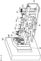
- FIG. 1 illustrates the appearance of a banknote handling apparatus 100
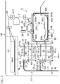
- FIG. 2 illustrates a general configuration for the banknote handling apparatus 100.
- the banknote handling apparatus 100 is placed on a teller counter of a bank, for example, and is used by an operator.
- the banknote handling apparatus 100 takes loose banknotes therein, stacks the banknotes of a predetermined kind, bundles the banknotes in a predetermined bundling number, and dispenses the bundled banknotes.
- the banknote handling apparatus 100 is an exemplary paper sheet processing device, and banknotes are an example of paper sheets.
- the banknote handling apparatus 100 includes a hopper unit 2 which takes the banknotes placed thereon into the apparatus, a recognition unit 3 which recognizes the banknotes, bundling stackers 4 which stack the banknotes to be bundled, non-bundling stackers 5 which stack the banknotes not to be bundled, a reject stacker 6 which stacks rejected banknotes, a bundling unit 9 which bundles the banknotes, a dispense unit 11 through which the banknotes that have been bundled (hereinafter referred to as "bundled banknotes”) are dispensed, a first transport unit 7 which transports the banknotes taken in through the hopper unit 2 to the recognition unit 3, the bundling stackers 4, the non-bundling stackers 5, and the reject stacker 6, a second transport unit 8 which transports the banknotes stacked in the bundling stackers 4 to the bundling unit 9, a third transport unit 10 which transports the bundled banknotes to the dispense unit 11, and a box-shaped housing 12 which houses the
- the housing 12 has a top surface 121, a bottom surface 122, and four side surfaces.
- the hopper unit 2 and the dispense unit 11 are provided for a first side surface 123, which is one of the four side surfaces of the housing 12.
- First outlets 413 of the bundling stackers 4 and second outlets 53 of the non-bundling stackers 5, which will be described in detail later, are provided through a second side surface 124, which is another one of the four side surfaces.
- the first and second side surfaces 123 and 124 are adjacent to each other.
- the space inside the housing 12 is divided into a first handling section 126 configured to perform various kinds of handling processing for recognizing and sorting the banknotes and a second handling section 127 configured to perform various kinds of handling processing for bundling the banknotes to be bundled.
- the second handling section 127 is provided above the first handling section 126.
- the first handling section 126 includes the hopper unit 2, the recognition unit 3, the non-bundling stackers 5, and the reject stacker 6.
- the second handling section 127 includes the bundling stackers 4, the second transport unit 8, the bundling unit 9, and the third transport unit 10. Most of the first transport unit 7 is included in the first handling section 126.
- the bundling stackers 4 include two stackers, namely, a first bundling stacker 4A and a second bundling stacker 4B. Both of the first and second bundling stackers 4A and 4B stack the banknotes to be bundled. The banknotes stacked as those to be bundled are determined as appropriate.
- the bundling stacker 4 is an exemplary stacking unit.
- the first and second bundling stackers 4A and 4B are arranged substantially vertically, i.e., one on top of the other, in the second handling section 127.
- the first bundling stacker 4A is positioned over the second bundling stacker 4B.
- the first and second bundling stackers 4A and 4B have the same configuration. When it is not necessary to distinguish the two stackers from each other, they will be hereinafter referred to as "bundling stackers 4." A detailed configuration of the bundling stackers 4 will be described later.
- the non-bundling stackers 5 include two stackers, namely, a first non-bundling stacker 5A and a second non-bundling stacker 5B.
- the first and second non-bundling stackers 5A and 5B are arranged substantially horizontally, i.e., side by side, in the first handling section 126.
- the second non-bundling stacker 5B is arranged closer to the hopper unit 2 than the first non-bundling stacker 5A is.
- non-bundling stackers 5 When it is not necessary to distinguish the two stackers from each other, they will be hereinafter referred to as "non-bundling stackers 5."
- a detailed configuration of the non-bundling stackers 5 will be described later.
- the banknotes to be stacked in the non-bundling stackers 5 may be determined as appropriate.
- the reject stacker 6 stacks the rejected banknotes.
- the reject stacker 6 is positioned closer to the hopper unit 2 than the first and second non-bundling stackers 5A and 5B are.
- the reject stacker 6 is positioned at a level slightly higher than the first and second non-bundling stackers 5A and 5B. A detailed configuration of the reject stacker 6 will be described later.
- the banknotes to be stacked in the reject stacker 6 may be determined as appropriate.
- the hopper unit 2 is provided for a portion of the first side surface 123 corresponding to the first handling section 126, and the dispense unit 11 is provided for a portion of the first side surface 123 corresponding to the second handling section 127.
- the hopper unit 2 includes a mount 21 on which banknotes are placed, two guides 22, 22 which guide the banknotes placed on the mount 21, taking-in rollers 23, an inlet 24 through which the banknotes are taken in, and a banknote sensor 25 which detects the banknotes on the mount 21.
- the banknotes are placed on the hopper unit 2 such that the banknotes are taken in in a direction parallel to their shorter edges.
- the hopper unit 2 is an exemplary taking-in unit.
- the banknote sensor 25 is provided near the inlet 24.
- the banknote sensor 25 includes a transmitter which emits light and a receiver which receives the light, and detects the banknotes when the light emitted from the transmitter toward the receiver is blocked.
- the banknote sensor 25 is arranged such that the light is blocked by the banknotes placed on the mount 21. That is to say, the banknote sensor 25 can detect that the banknotes are placed on the mount 21 when the light is blocked.
- First and second banknote sensors 411 and 412, stacking sensors 52 and 62, tracking sensors 74, first and second tape sensors 9210 and 9211, and first and second sensors 117 and 118 to be described later are also configured in the same manner.
- the dispense unit 11 receives the bundled banknotes at a receiving position above the hopper unit 2, and allows the bundled banknotes to slide laterally from the receiving position to a dispensing position so that the bundled banknotes are dispensed outside the housing 12 through a dispense port 111.
- the dispense unit 11 dispenses the bundled banknotes along their shorter edges through the dispense port 111.
- the first transport unit 7 may be configured as a transport belt or any other suitable member.
- the first transport unit 7 includes a main transport path 71, first to fourth diverged paths 72a to 72d diverged from the main transport path 71, sorting mechanisms 73 provided at junctions between the main transport path 71 and the diverged paths, and a plurality of tracking sensors 74 which detect the passage of the banknotes.
- the first transport unit 7 transports the banknotes in the direction parallel to their shorter edges.
- the main transport path 71 extends from the taking-in rollers 23 through the first bundling stacker 4A.
- the first diverged path 72a is the most upstream path in the main transport path 71, and the second, third, and fourth diverged paths 72b, 72c and 72d are arranged in this order downstream of the first diverged path 72a.
- diverged paths 72 When it is not necessary to distinguish the first to fourth diverged paths 72a to 72d from each other, they will be hereinafter referred to as "diverged paths 72."
- the first diverged path 72a extends to reach the reject stacker 6.
- the second diverged path 72b extends to reach the second non-bundling stacker 5B.
- the third diverged path 72c extends to reach the first non-bundling stacker 5A.
- the fourth diverged path 72d extends to reach the second bundling stacker 4B.
- the sorting mechanisms 73 are driven by a solenoid (not shown). Each of the sorting mechanisms 73 sorts the banknotes transported through the main transport path 71 depending on whether they need to be diverged to an associated one of the diverged paths 72 or not.
- a tracking sensor 74 is provided upstream of each of the sorting mechanisms 73.
- the tracking sensors 74 are configured in the same manner as the banknote sensor 25. That is, the tracking sensors 74 can detect the passage of the banknotes if the reception of light by the receiver of the tracking sensor 74 is temporarily interrupted and then resumed. In guiding the banknotes to the diverged path 72, each sorting mechanism 73 is turned ON as soon as the tracking sensor 74 immediately upstream thereof detects the passage of the banknotes.
- the recognition unit 3 is provided on the main transport path 71 upstream of the first diverged path 72a.
- the recognition unit 3 is configured to recognize each of the banknotes being transported in terms of their denomination, authenticity, and fitness.
- the recognition unit 3 includes a line sensor 31 and a magnetic sensor 32, and detects the feature of each banknote.
- the recognition unit 3 determines whether the feature of the banknote thus detected corresponds with any of the stored features of the banknotes, thereby making a determination about their denomination, authenticity, and fitness.
- the bundling unit 9 bundles the stacked banknotes. As will be described in detail later, the bundling unit 9 forms a tape loop L, and rewinds the tape after the banknotes have been transported into the tape loop L so that the banknotes are bundled with the tape.
- the second transport unit 8 grips the banknotes stacked in the bundling stacker 4 to transport the banknotes into the tape loop L.
- the second transport unit 8 includes a gripper 81 which grips the banknotes, a first horizontal displacement mechanism which displaces the gripper 81 in the horizontal direction parallel to the shorter edges of the banknotes (this direction will be hereinafter referred to as a "first horizontal direction"), a second horizontal displacement mechanism which displaces the gripper 81 in the horizontal direction parallel to the longer edges of the banknotes (hereinafter referred to as a "second horizontal direction”), and a vertical displacement mechanism which displaces the gripper 81 in the vertical direction.
- the second transport unit 8 is an exemplary pre-bundling transport unit.
- FIG. 3 illustrates an enlarged schematic view of the gripper 81.
- the gripper 81 includes an upper arm 81 a, a lower arm 81b facing the upper arm 81 a, and a gripping mechanism which displaces the upper arm 81 a in the vertical direction.
- the upper arm 81 a includes three fingers extending parallel to each other and a coupling portion which couples the three fingers together.
- the lower arm 81b also has three fingers extending parallel to each other and a coupling portion which couples the three fingers together.
- a portion 81c of the upper arm 81a abutting the banknotes B (i.e., an inner portion thereof, which will be hereinafter referred to as an "abutting portion”) and a portion 81d of the lower arm 81b abutting the banknotes B (i.e., an inner portion thereof, which will be hereinafter referred to as an "abutting portion”) are made of urethane rubber.
- the abutting portions 81c and 81d may be made of any other rubber than the urethane rubber or a resin.
- the gripping mechanism supports the upper arm 81 a so that the upper arm 81 a is movable in the vertical direction, and moves the upper arm 81 a in the vertical direction using a motor and a drive belt. This configuration allows the upper and lower arms 81a and 81b to grip the banknotes.
- the first horizontal displacement mechanism supports the gripper 81 so that the gripper 81 is movable in the first horizontal direction, and displaces the gripper 81 in the first horizontal direction using the motor and the drive belt.
- the vertical displacement mechanism supports the first horizontal displacement mechanism so that the first horizontal displacement mechanism is movable in the vertical direction, and displaces the first horizontal displacement mechanism in the vertical direction using the motor and the drive belt.
- the second horizontal displacement mechanism supports the vertical displacement mechanism so that the vertical displacement mechanism is movable in the second horizontal direction, and displaces the vertical displacement mechanism in the second horizontal direction using the motor and the drive belt.
- the gripper 81 is configured to be movable in the direction along three orthogonal axes by the first and second horizontal displacement mechanisms and the vertical displacement mechanism.
- FIG. 4 illustrates an enlarged schematic view of the third transport unit 10.
- the third transport unit 10 receives the bundled banknotes from the second transport unit 8, and transports the bundled banknotes to the dispense unit 11.
- the third transport unit 10 includes an upper gripping part 101, a lower gripping part 102, and a horizontal displacement mechanism which displaces the upper and lower gripping parts 101 and 102 in the first horizontal direction.
- the third transport unit 10 is an exemplary post-bundling transport unit.
- a portion 101a of the upper gripping part 101 abutting the banknotes B (i.e., an inner portion and will be hereinafter referred to as an "abutting portion”) and a portion 102a of the lower gripping part 102 abutting the banknotes B (i.e., an inner portion and will be hereinafter referred to as an "abutting portion”) are made of urethane rubber.
- the abutting portions 101 a and 102a may be made of any other rubber than the urethane rubber or a resin.
- the third transport unit 10 is configured to pass beside the bundling unit 9 in the first horizontal direction.
- the third transport unit 10 receives the bundled banknotes supported by the second transport unit 8 on the way while moving in the first horizontal direction from the bundling stacker 4 side to the dispense unit 11 side.
- the third transport unit 10 is located closer to the bundling stacker 4, the upper gripping part 101 is positioned over, and sufficiently distant from, the lower gripping part 102.
- the upper gripping part 101 moves downward from this position as it approaches the dispense unit 11.
- the upper gripping part 101 reaches the bundled banknotes supported by the second transport unit 8, the bundled banknotes are gripped by the upper and lower gripping parts 101 and 102.
- the upper and lower gripping parts 101 and 102 transport the bundled banknotes to the vicinity of the dispense unit 11 while gripping them. In the vicinity of the dispense unit 11, the upper gripping part 101 moves upward as it approaches the dispense unit 11. As a result, the bundled banknotes gripped by the upper and lower gripping parts 101 and 102 are released from the upper and lower gripping parts 101 and 102 at the dispense unit 11, and are dispensed to the dispense unit 11.
- a touch panel 17 is provided to serve as an operating unit through which information is entered into the banknote handling apparatus 100 and as a display unit which displays information about the banknote handling apparatus 100.
- the touch panel 17 is a human interface for the operator who operates this banknote handling apparatus 100.
- FIG. 5 illustrates a general configuration for the bundling stackers 4 and the bundling unit 9.
- the bundling stackers 4 pile and stack the banknotes B that have been transported through the first transport unit 7.
- the banknotes B are transported in the direction parallel to their shorter edges with one of their longer edges facing front before entering the bundling stackers 4.
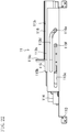
- Each of the bundling stackers 4 includes a stage 41 which carries the banknotes B thereon, a guide 42 which aligns the respective longer edges of the banknotes B at the frontend in their transport direction, a rear wall 43 facing the longer edges of the banknotes B at the rearend in their transport direction, a ceiling 45 of the bundling stacker 4, a door 46 (see FIG. 1 ) which covers/uncovers the bundling stacker 4, a positioning unit 47 (see FIG.
- first edge b1 one of the shorter edges of the banknote B facing the positioning unit 47
- second edge b2 one of the longer edges of the banknote B at the frontend in the transport direction
- third edge b3 the other shorter edge opposite to the first edge b1
- fourth edge b4 the other longer edge at the rearend in the transport direction
- the stage 41 is configured to be movable in a vertical direction which is a piling direction of the banknotes B.
- the stage 41 moves in accordance with the amount of the banknotes B stacked thereon.
- the guide 42 blocks the banknotes B transported into the bundling stacker 4 from moving in their transport direction, and allows the banknotes B to fall onto the stage 41.
- the banknotes that have fallen onto the stage 41 have their second edge b2 facing the guide 42, and their fourth edge b4 facing the rear wall 43.
- the stacking wheel 410 includes a plurality of flexible blades, and has the function of tapping the banknotes B transported into the bundling stacker 4 on their rear edges in the transport direction so as to help the banknotes B fall. Even when the banknotes B are brought into the bundling stacker 4 successively, each of the banknotes B is prevented from being inserted below the rear edge of the preceding banknote B, and thus the banknotes B can be sequentially stacked one by one on top of the previously stacked ones.
- the first outlet 413 and the door 46 are provided on the first edge b1 side of the banknotes B on the stage 41.
- the positioning unit 47 is provided on an inner side of the door 46, i.e., a portion of the door 46 facing the first edge b1 of the banknotes B.
- the alignment mechanism 49 is provided on the third edge b3 side of the banknotes B.
- the alignment mechanism 49 pushes the third edge b3 of the banknotes B in the direction parallel to their longer edges to bring the first edge b1 of the banknotes B into contact with the positioning unit 47.
- the positioning unit 47 and the alignment mechanism 49 align at least the respective first edges b1 of the banknotes B with each other.
- the first banknote sensor 411 includes a transmitter 411a, a prism 411c, and a receiver 411b, and is arranged to emit light in the stacking direction (i.e., the piling direction) of the banknotes B at two different positions in the transport direction of the banknotes B.
- the first banknote sensor 411 detects the presence of the banknotes B when the light is blocked in at least one of the two positions.
- the second banknote sensor 412 is configured to detect the banknotes B located at a predetermined height in the bundling stacker 4.
- the second banknote sensor 412 is configured in the same manner as the banknote sensor 25.
- the second banknote sensor 412 is arranged to emit light at a predetermined height in a direction parallel to the surface of the stage 41 and parallel to the longer edges of the banknotes B. In FIG. 5 , for the sake of easy description, the second banknote sensor 412 is illustrated as emitting light in a direction parallel to the shorter edges of the banknotes B.
- the second banknote sensor 412 is arranged such that light emitted from the transmitter to the receiver is blocked by the banknotes B when the banknotes B are present at a level higher than the predetermined height, and that the light emitted from the transmitter reaches the receiver when the banknotes B are not present at the level higher than the predetermined height.
- each of the non-bundling stackers 5 pile and stack the banknotes.
- each of the non-bundling stackers 5 includes a container 50 in which the banknotes are stacked, a stacking wheel 51 which brings the transported banknotes into the container 50, and a stacking sensor 52 which detects the presence or absence of the banknotes.
- the container 50 of each of the non-bundling stackers 5 has a tilted bottom. Thus, the banknotes brought into the container 50 are collected to the lower end of the bottom.
- the stacking sensor 52 is provided at the lower end of the bottom of the container 50.
- the stacking sensor 52 is configured in the same manner as the banknote sensor 25, and detects the banknotes in the container 50 when the light is blocked.
- the stacking sensor 52 is arranged such that the light is blocked by the banknotes in the container 50.
- the stacking wheel 51 includes a plurality of blades, and catches the transported banknotes between the blades to bring them into the container 50.
- the banknotes are released from the blades of the stacking wheel 51 near the bottom of the container 50, and are stacked in the container 50.
- the container 50 has openings through the second side surface 124 of the housing 12 as shown in FIG. 1 . That is to say, the second side surface 124 is provided with second outlets 53 through which the banknotes stacked in the non-bundling stackers 5 are removed out of the housing 12.
- the second outlets 53 have no door, and are kept opened.
- the second outlets 53 of the first and second non-bundling stackers 5A and 5B are cut open through the second side surface 124 and are arranged side by side in the horizontal direction.
- Each of the non-bundling stackers 5 is provided with a pushing mechanism 54 which pushes the stacked banknotes toward the second outlet 53.
- the pushing mechanism 54 is provided at the back of the container 50 (the side opposite to the second outlet 53), and is configured to push out the banknotes from the back to the front (the side of the second outlet 53).
- the reject stacker 6 piles and stacks the banknotes.
- the reject stacker 6 includes, as shown in FIG. 2 , a container 60 in which the banknotes are stacked, a stacking wheel 61 which brings the transported banknotes into the container 60, a stacking sensor 62 which detects the presence or absence of the banknotes, and stoppers 64, 64 which prevent the banknotes in the container 60 from being ejected outside.
- the container 60 of the reject stacker 6 has an opening through the first side surface 123 of the housing 12 as shown in FIG. 1 . That is, a reject outlet 63 through which the banknotes stacked in the reject stacker 6 are removed out of the housing 12 is provided through the first side surface 123. The reject outlet 63 is cut open through the first side surface 123 to be positioned above the inlet 24. The reject outlet 63 has no door and is kept opened.
- the bottom of the container 60 is tilted such that the more distant from the first side surface 123, the lower the level of the bottom.
- the banknotes in the container 60 are stacked deep inside the first side surface 123. In this manner, the banknotes are prevented from being ejected outside through the reject outlet 63 of the first side surface 123 when they are brought into the container 60.
- the two stoppers 64, 64 are provided at one edge of the bottom of the container 60 closer to the first side surface 123.
- the stoppers 64 are supported to be rotatable around an axis extending parallel to the edge of the bottom closer to the first side surface 123, and are biased by bias springs (not shown) to stand up on the bottom of the container 60.
- These stoppers 64, 64 can also prevent the banknotes in the container 60 from being ejected outside through the reject outlet 63 of the first side surface 123. Note that the banknotes stacked in the reject stacker 6 may be removed through the reject outlet 63 with the stoppers 64, 64 pressed down against the elastic force of the bias springs.
- the stacking wheel 61 includes a plurality of flexible blades, and has the function of tapping the banknotes falling into the container 60 on their rear edges in the transport direction so as to help the banknotes fall. Even when the banknotes are brought into the container 60 successively, each of the banknotes is prevented from being inserted below the rear edge of the preceding banknote, and thus the banknotes can be sequentially stacked one by one on top of the previously stacked ones.
- the stacking sensor 62 is configured in the same manner as the banknote sensor 25, and detects the banknotes in the container 60 when the light is blocked.
- the stacking sensor 62 is arranged such that the light is blocked by the banknotes in the container 60.
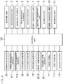
- FIG. 6 is a block diagram illustrating a general configuration for the banknote handling apparatus 100.
- the banknote handling apparatus 100 includes a control unit 120 based on a well-known processor, for example, and a memory (not shown).
- the control unit 120 is connected to the above-described units, namely, the hopper unit 2, the recognition unit 3, the bundling stackers 4, the non-bundling stackers 5, the reject stacker 6, the first and second transport units 7 and 8, the bundling unit 9, the third transport unit 10, the dispense unit 11, and the touch panel 17 so as to transmit and receive signals to/from these units.
- the control unit 120 is also connected to the banknote sensor 25, the first and second banknote sensors 411 and 412, the stacking sensors 52 and 62, the tracking sensors 74, the first and second tape sensors 9210 and 9211, and the first and second sensors 117 and 118 to receive detection signals from these sensors.
- the control unit 120 generates a control signal based on the signal supplied from the touch panel 17, the detection signals from the sensors and other suitable signals, and outputs the generated control signal to the hopper unit 2 and other units.
- the hopper unit 2 and other units operate in accordance with the control signal. Taking the bundling stacker 4 as an example, the control unit 120 controls the stage 41, the guide 42, a locking mechanism 46c (to be described later), the alignment mechanism 49, and the stacking wheel 410.
- the memory stores various kinds of information such as dimensions of different banknotes B.
- the operator receives loose banknotes to be deposited from the customer, and places the banknotes on the hopper unit 2. At this time, even if the loose banknotes include banknotes of multiple different kinds, all the banknotes are just placed on the hopper unit 2 without being sorted.
- the operator adjusts the guides 22 according to the dimensions of the banknotes. Then, the operator operates the touch panel 17 to start the intake of the banknotes.
- the banknote handling apparatus 100 may automatically start the intake of the banknotes when the banknote sensor 25 detects the banknotes placed on the hopper unit 2.
- the banknotes placed on the hopper unit 2 are brought into the housing 12 one by one through the inlet 24 as the taking-in rollers 23 are activated.
- the banknotes thus taken in are transported by the first transport unit 7, and pass through the recognition unit 3.
- the recognition unit 3 detects the kind of the banknotes passed, and informs the control unit 120 of the kind of the banknotes.
- the control unit 120 designates the banknotes' destination according to the kind of the banknotes. In particular, if the banknotes are fit banknotes of a predetermined denomination to be bundled, the control unit 120 designates the bundling stacker 4 (any one of the bundling stackers 4A and 4B) as their destination. If the banknotes are unfit banknotes of the predetermined denomination to be bundled, the control unit 120 designates the first non-bundling stacker 5A as their destination. If the banknotes are of any denomination other than the predetermined denomination, the control unit 120 designates the second non-bundling stacker 5B as their destination. If the banknotes are rejected banknotes, the control unit 120 designates the reject stacker 6 as their destination.
- the control unit 120 controls the first transport unit 7 such that the banknotes are transported to the stacker designated as their destination.
- the control unit 120 controls the sorting mechanism 73 corresponding to the diverged path 72 leading to the destination stacker such that the banknotes are guided from the main transport path 71 to the diverged path 72.
- the control unit 120 switches the sorting mechanism 73 when the tracking sensor 74 just before the diverged path 72 detects the banknotes.
- the control unit 120 controls the stacking wheel 410, 51 or 61 of the destination stacker to bring the banknotes into that stacker.
- the banknotes to be transported to the bundling stacker 4 are transported to one of the two bundling stackers 4.
- a predetermined bundling number e.g. 100
- the remaining banknotes are then transported to the other bundling stacker 4.
- the banknotes are supposed to be transported to the first bundling stacker 4A first.
- the stacking wheel 410 rotates to stack the banknotes one by one.
- the control unit 120 controls the second transport unit 8 so that the gripper 81 grips the banknotes in the first bundling stacker 4A to transport them to the bundling unit 9. Thereafter, the control unit 120 instructs the bundling unit 9 to bundle the banknotes with a tape T.
- the two bundling stackers 4 makes it possible to perform the bundling processing while stacking the banknotes continuously.
- control unit 120 controls the third transport unit 10 and the dispense unit 111 so that the bundled banknotes are dispensed through the dispense unit 111.
- the unfit banknotes of the predetermined denomination are transported to the first non-bundling stacker 5A.
- the stacking wheel 51 rotates to stack the transported banknotes in the container 50.
- the unfit banknotes of the predetermined denomination are stacked in the first non-bundling stacker 5A.
- the banknotes of any denominations other than the predetermined denomination are transported to, and stacked in, the second non-bundling stacker 5B.
- the rejected banknotes are also transported to, and stacked in, the reject stacker 6.
- banknote sensor 25 detects whether banknotes are still present on the hopper unit 2 or not.
- the rejected banknotes are taken in and recognized again. Specifically, the operator extracts the rejected banknotes from the reject stacker 6, and places them on the hopper unit 2 to take them into the apparatus again.
- the rejected banknotes are those which were not recognized as normal banknotes for any reason, and thus another attempt is made to take in and recognize them.
- Banknotes still recognized as rejected banknotes, if any, are restacked in the reject stacker 6. Then, the operator returns those restacked banknotes to the customer.
- the single kind banknote bundling processing is finished, i.e., the counting and sorting of the banknotes passed as those to be deposited by the customer are finished.
- the touch panel 17 displays the counted amount of the banknotes. The operator asks for a customer's approval of the amount, or checks whether the displayed amount corresponds with the amount written down on a deposit slip by the customer, and, if the answer is YES, the operator operates the touch panel 17 to confirm the deposit amount. When the confirmation is done, a host device (not shown) is informed of the confirmed deposit amount, thereby finishing the deposit processing.
- the operator takes out the bundled banknotes dispensed from the dispense unit 11, the banknotes stacked in the bundling stackers 4, and the banknotes stacked in the non-bundling stackers 5, and stores them in a predetermined storage place.
- loose banknotes of different kinds are sorted into fit banknotes of a predetermined denomination, unfit banknotes of the predetermined denomination, banknotes of every denomination but the predetermined denomination, and rejected banknotes.
- the fit banknotes of the predetermined denomination are bundled based on a bundling number of banknotes.
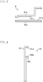
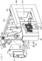
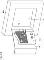
- FIG. 7 is a perspective view illustrating the bundling stacker 4 with a portion thereof omitted.
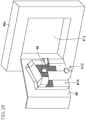
- FIG. 8 is a perspective view illustrating the bundling stacker 4 with a portion thereof omitted, as viewed from a different direction from FIG. 7 .
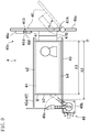
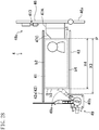
- FIG. 9 is a plan view illustrating generally the bundling stacker 4 with a portion thereof omitted.
- the stage 41 is configured to be movable in a vertical direction which is a piling direction of the banknotes B. Specifically, the stage 41 is coupled to a vertical mover 41a, which is secured to a vertically extending shaft (not shown) so as to be movable up and down, and which is driven vertically by a motor (not shown).
- the stage 41 has a comb-tooth shape.
- the banknotes B are stacked at a predetermined stacking position on the stage 41. When the banknotes B are at this stacking position, their first edge b1 is in contact with the positioning unit 47. Specifically, as will be described in detail later, the banknotes B are stacked with their first edge b1 substantially in contact with the positioning unit 47.
- the guide 42 is configured to be movable in the transport direction of the banknotes B.
- the guide 42 is comprised of an upper guide 42a and a lower guide 42b.
- the upper guide 42a is mounted to a rotatable shaft 42d provided for a pair of frames 42c, 42c which moves in the transport direction of the banknotes B.
- the pair of frames 42c, 42c is movably mounted to a horizontal shaft (not shown) extending in the transport direction, and is driven by a motor (not shown) along the horizontal shaft.
- the rotatable shaft 42d is supported rotatably by the pair of frames 42c, 42c.
- the upper guide 42a is integrally attached to the rotatable shaft 42d.
- the rotatable shaft 42d is biased by a torsion spring 42e in a direction around its shaft center.
- the upper guide 42a rotates along with the rotatable shaft 42d.
- the lower guide 42b is fixed on the pair of frames 42c, 42c.
- the lower guide 42b is provided under the upper guide 42a.
- the upper guides 42a are formed to have a shape with four comb teeth.
- the lower guides 42b are also formed to have such a shape with four comb teeth.
- the upper guide 42a is biased by the torsion spring 42e in a direction around the rotatable shaft 42d, and a tip end of the upper guide 42a is in contact with a tip end of the lower guide 42b.
- the upper guide 42a is hanging down from the rotatable shaft 42d.
- the upper guide 42a and the lower guide 42b form a wall at the frontend of the transport direction for the bundling stacker 4.
- the respective comb teeth of the upper and lower guides 42a and 42b define three slits extending vertically. Two outer ones of these three slits are arranged at such positions as to allow two comb teeth of the stage 41 to enter the slits.
- the upper and lower guides 42a and 42b move back and forth in the transport direction of the banknotes B.
- the comb teeth of the stage 41 enter the slits formed by the respective comb teeth of the upper and lower guides 42a and 42b, thereby substantially preventing the stage 41 from interfering with the upper and lower guides 42a and 42b.
- the slits extend vertically, the interference between the comb teeth of the stage 41 and the upper and lower guides 42a and 42b is also avoidable even if the stage 41 moves vertically.
- the upper guide 42a is able to turn forward in the transport direction against the biasing force applied by the torsion spring 42e, thereby opening the bundling stacker 4 forward in the transport direction.
- the rear wall 43 is arranged as a stationary member in the bundling stacker 4. As shown in FIG. 8 , a plurality of second catching grooves 44, 44 are formed at an upper end of the rear wall 43.
- the second catching grooves 44 extend along the fourth edge b4 of the banknotes B stacked on the stage 41. That is, the second catching grooves 44 extend parallel to a surface 41b of the stage 41.
- the plurality of second catching grooves 44, 44, ... are arranged in the piling direction of the banknotes B, i.e., the vertical direction.
- the second catching grooves 44 prevent the banknotes B, transported into the bundling stacker 4 and falling onto the stage 41, from entering a gap between a bundle of banknotes on the stage 41 and the rear wall 43 (or a gap between the stage 41 and the rear wall 43 if no bundles of banknotes are present on the stage 41).
- a generally square frame 46a which has a first outlet 413 in a generally square shape.
- the door 46 is attached so as to be pivotable freely on a shaft provided on one side of the frame 46a.
- the door 46 rotates to change between an open state where the first outlet 413 is open and a closed state where the first outlet 413 is closed.
- the door 46 is biased to such a direction as to have the open state by a coil spring (not shown) provided for the shaft.
- the door 46 is made of a material which allows visual check of the inside of the bundling stacker from outside.
- the door 46 may be made of a transparent or translucent material (e.g., glass or a resin).
- the door 46 is also provided with a locking mechanism 46c as shown in FIG. 9 .
- the locking mechanism 46c is configured to be switchable between a locked state in which the door 46 is locked to the closed state and an unlocked state in which the door 46 is allowed to open and close freely.
- the locking mechanism 46c includes a pin 46d provided for the frame 46a, a drive mechanism 46e including a solenoid or any other components for driving the pin 46d, and an engaging portion 46f provided for the door 46 and engaging with the pin 46d.
- the locking mechanism 46c is controlled by the control unit 120 individually on a bundling stacker (4) basis. That is to say, its door 46 is openable and closable individually.
- the positioning unit 47 is provided on the inner side of the door 46.
- the positioning unit 47 comes into contact with the first edge b1 of the banknotes B, thereby placing the first edge b1 at a predetermined alignment position P.
- the positioning unit 47 is made of a material which allows visual check of the inside of the positioning unit 47 from outside.
- the positioning unit 47 may be made of a transparent or translucent material (e.g., glass or a resin).
- the positioning unit 47 includes multiple types of positioning units, and a second positioning unit 47B is attached in the example shown in FIGS. 7 to 9 . When it is not necessary to distinguish the types of positioning units 47, they may be hereinafter referred to as the "positioning units 47" collectively.
- a plurality of first catching grooves 48, 48, ... are formed at a portion of the positioning unit 47 as shown in FIGS. 7 and 8 .
- the first catching grooves 48 extend along the first edge b1 of the banknotes B stacked on the stage 41. That is, the first catching grooves 48 extend parallel to the surface 41b of the stage 41.
- the plurality of first catching grooves 48, 48, ... are arranged in the piling direction of the banknotes B, i.e., the vertical direction.
- the first catching grooves 48, 48, ... are formed in a relatively upper portion of the positioning unit 47.
- the first catching grooves 48 function as a catching unit which catches the first edge b1 of the banknotes B, when they lean on the positioning unit 47 while stacking, in cooperation with the movement of the stage 41.
- the alignment mechanism 49 is provided at the other end of the bundling stacker 4 opposite from the door 46. That is to say, the alignment mechanism 49 is provided so as to face the third edge b3 of the banknotes B in the bundling stacker 4 opposite from the door 46.
- the alignment mechanism 49 aligns the respective edges of the banknotes in the width direction with each other. In this embodiment, as the banknotes are transported in the direction parallel to their shorter edges, the width direction corresponds to the direction parallel to the longer edges of the banknotes. In other words, the alignment mechanism 49 aligns the respective shorter edges of the banknotes.
- the alignment mechanism 49 includes an arm 49a which is provided to be rotatable on a shaft extending in the stacking direction of the banknotes B and a stepping motor 49b which rotates the arm 49a.
- the alignment mechanism 49 brings the first edge b1 of the banknotes B into contact with the positioning unit 47. That is to say, the alignment mechanism 49 aligns the respective shorter edges of the banknotes B in cooperation with the door 46. In this manner, the banknotes B in the bundling stacker 4 are aligned with each other in contact with the positioning unit 47.
- the alignment mechanism 49 is an exemplary pushing unit.
- the arm 49a After pushing the banknotes B toward the positioning unit 47, the arm 49a stays at the position where the arm 49a has moved the banknotes B (i.e., a position at which the distance between the arm 49a and the positioning unit 47 is substantially equal to the dimension of the longer edges of the banknotes B), and functions at that position as a regulating unit configured to regulate the movement of the banknotes B toward the alignment mechanism 49 in the direction parallel to their longer edges.
- the alignment mechanism 49 is configured to be able to adjust the magnitude of movement of the arm 49a, and adjusts the magnitude of movement of the arm 49a according to the kind of the banknotes B and the type of the positioning unit 47. Specifically, the magnitude of movement of the arm 49a is adjusted such that the arm 49a turns to a position where the distance between the arm 49a and the positioning unit 47 is substantially equal to the dimension of the longer edges of the banknotes B to be stacked. Thus, the magnitude of movement of the alignment mechanism 49 pushing the third edge b3 of the banknotes B is adjusted according to the dimension of the longer edges of the banknotes B and the alignment position P of the positioning unit 47.
- the bundling stacker 4 includes two first banknote sensors 411.
- the two first banknote sensors 411 are arranged in the direction parallel to the longer edges of the banknotes B.
- the stage 41 has two pairs of the first and second holes 41c and 41d.
- Each of the first banknote sensors 411 includes a transmitter 411a which emits light, a receiver 411b which receives light, and a prism 411c which guides the light from the transmitter 411a to the receiver 411b as shown in FIG. 5 .
- the transmitter 411a and the receiver 411b are arranged side by side on the ceiling 45 in the transport direction of the banknotes B.
- the transmitter 411 a is arranged to emit light downward
- the receiver 411b is arranged to receive light coming from below.
- the prism 411c is arranged on the bottom of the bundling stacker 4.
- the prism 411c includes a light entering portion 411d, a light exiting portion 411e, and two reflective planes, and is formed in a substantially U-shape.
- the light entering portion 411d faces the transmitter 411 a
- the light exiting portion 411e faces the receiver 411b.
- the light entering portion 411 d and the light exiting portion 411e are arranged side by side in the transport direction of the banknotes, and face upward.
- Light incident on the light entering portion 411 d is reflected from the two reflective planes to emerge upward out of the prism 411c through the light exiting portion 411e.
- the light directed from the transmitter 411 a toward the light entering portion 411d passes through the first hole 41c of the stage 41, and the light directed from the light exiting portion 411e toward the receiver 411b passes through the second hole 41d of the stage 41.
- the stage 41 is moved to the lowermost position, the light entering portion 411d is inserted in the first hole 41c, and the light exiting portion 411e is inserted in the second hole 41d.
- the traveling direction of the light directed from the transmitter 411a to the light entering portion 411d and the traveling direction of the light directed from the light exiting portion 411e to the receiver 411b agree with the moving direction of the stage 41, i.e., the vertical direction.
- the stage 41 moves in the vertical direction
- the light emitted from the transmitter 411 a passes through the first hole 41c to be incident on the light entering portion 411d, while the light emerging from the light exiting portion 411e passes through the second hole 41d to be incident on the receiver 411b. That is, even when the stage 41 moves up or down, an optical path leading from the transmitter 411a to the receiver 411b is ensured.
- the banknotes B are present on the stage 41, the light directed from the transmitter 411a toward the receiver 411b is blocked. Thus, the presence of the banknotes B in the bundling stacker 4 is detected. At this time, the light passes through two different points in the transport direction of the banknotes B, and the two first banknote sensors 411 are arranged side by side in the direction parallel to the longer edges of the banknotes B. Thus, four beams of light pass through mutually different points in the directions parallel to the longer and shorter edges of the banknotes B. As a result, even if the position of the banknotes B varies, at least one of these beams of light is blocked, and thus the presence of the banknotes B may accurately be detected.
- the transmitter 411 a, the receiver 411b, and the prism 411c are located at fixed positions, the optical axes of the first banknote sensors 411 do not fluctuate even when the stage 41 moves up and down. Thus, the presence or absence of the banknotes B may accurately be detected.
- control unit 120 controls the bundling stacker 4.
- the control unit 120 has the stage 41 moved to an initial position before the banknotes B are transported to the bundling stacker 4.
- the initial position of the stage 41 is a relatively upper position close to the stacking wheel 410. At this initial position, the distance for the banknotes B falling into the bundling stacker 4 may be relatively short, which may stabilize the position toward which the banknotes B fall. Note that the initial position of the stage 41 is lower than the level of the second banknote sensor 412.
- control unit 120 allows the guide 42 to move to a position associated with the kind of the banknotes B transported to the bundling stacker 4.
- the banknotes B are transported with their shorter edges parallel to the transport direction.
- the position of the guide 42 is adjusted according to the dimension of the shorter edges of the banknotes B.
- the guide 42 is arranged at a position where the distance between the guide 42 and the rear wall 43 is slightly larger than the dimension of the shorter edges of the banknotes B transported to the bundling stacker 4.
- the banknotes B are transported to the bundling stacker 4.
- the banknotes B transported to the bundling stacker 4 have momentum in the transport direction.
- the second edge b2 of the banknotes B at the frontend in their transport direction abut the guide 42, and the banknotes B fall onto the stage 41 by themselves.
- the stacking wheel 410 helps the banknotes B fall. Specifically, the stacking wheel 410 taps the banknote B transported to the bundling stacker 4 downward on its rear edge in the transport direction. Thus, the banknote B tend to fall with its rear edge going ahead of (i.e., reaching a lower level earlier than) its front edge. In addition, when being tapped by the stacking wheel 410 on its rear edge, the banknote B may be drawn toward the stacking wheel 410, i.e., toward the rearend in the transport direction.
- the rear edge of the banknote B may enter a gap between the bundle of banknotes on the stage 41 and the rear wall 43 (or a gap between the stage 41 and the rear wall 43 if no bundles of banknotes are present on the stage 41).
- the second catching grooves 44, 44, ... are provided at a top end of the rear wall 43.
- the fourth edge b4 of the banknote B which is going to enter the gap between the bundle of banknotes and the rear wall 43, may be caught in one of the second catching grooves 44 and blocked from entering the gap. In this way, the banknotes B transported to the bundling stacker 4 fall onto the stage 41 appropriately.
- the banknotes B on the stage 41 have their second edge b2 substantially in contact with the guide 42.
- the fourth edge b4 of the banknotes B faces the rear wall 43 with a small gap left between the fourth edge b4 and the rear wall 43.
- the fourth edge b4 of some banknotes B may be in contact with the rear wall 43.
- the control unit 120 allows the stage 41 to descend by a distance corresponding to the thickness of a predetermined number of banknotes, every time the number of banknotes stacked in the bundling stacker 4 increases by the predetermined number (e.g., 10).
- the level of the uppermost one of the banknotes B on the stage 41 (will be hereinafter referred to as an "uppermost banknote"), or the level of the stage 41 (if no banknotes B are present on the stage 41), may be adjusted within a predetermined range. This allows for keeping the distance for the banknotes falling into the bundling stacker 4 to travel within a substantially constant range, thus enabling the banknotes falling freely to be stacked at the substantially same position and with the substantially same posture.
- the control unit 120 checks whether the second banknote sensor 412 detects the banknotes B or not, every time the banknote B is transported to the bundling stacker 4. In a normal state, the second banknote sensor 412 does not detect any banknotes B. However, if the second banknote sensor 412 detects the banknotes B, the control unit 120 allows the stage 41 to descend by a predetermined distance. The descending distance corresponds to, or is slightly greater than, the thickness of the predetermined number of banknotes B. Thus, the second banknote sensor 412 is in a state in which the second banknote sensor 412 does not sense the banknotes.
- the control unit 120 basically allows the stage 41 to descend every time the number of the banknotes stacked increases by the predetermined number. If the level of the uppermost banknote B exceeds the highest level that can be detected by the second banknote sensor 412, the control unit 120 allows the stage 41 to descend in a way different from the basic descending control.
- the thickness of the bundle of banknotes B may vary depending on the state of the banknotes B even if the number of banknotes is the same.
- the distance for the banknotes to fall in the bundling stacker 4 may be maintained within the substantially constant range by combining the control of the stage 41 based on the number of banknotes B and the control of the stage 41 based on the monitored level of the uppermost banknote B.
- the control unit 120 actuates the arm 49a of the alignment mechanism 49 every time a single banknote B is transported to the bundling stacker 4.
- the banknote B is pushed in the direction parallel to its longer edges toward the positioning unit 47 on the door 46, and then the first edge b1 of the banknote B comes into contact with the positioning unit 47 on the door 46. In this way, both of the shorter edges of the stacked banknotes B are aligned.
- the control unit 120 allows the stage 41 to move upward to compress the stacked banknotes B between the stage 41 and the ceiling 45 until their combined thickness becomes equal to a predetermined thickness. If the combined thickness of the banknotes B that have fallen freely to, and been stacked on, the stage 41 is smaller than the predetermined thickness (e.g., if the banknotes B are new banknotes), the banknotes B are not compressed even if the stage 41 moves upward.
- the control unit 120 instructs the gripper 81 of the second transport unit 8 to grip the banknotes B.
- the gripper 81 has such a shape that enables the gripper 81 to enter the gaps between the comb teeth of the guide 42 and the gaps between the comb teeth of the stage 41, which allows the gripper 81 to grip the banknotes B on the stage 41 without any interference with the guide 42 or the stage 41.
- the second transport unit 8 draws the banknotes B, being gripped by the gripper 81, to the front in the transport direction.
- the upper guide 42a of the guide 42 is biased by a biasing force of the torsion spring 42e toward the direction in which the bundling stacker 4 is closed (toward the direction in which the tip end of the upper guide comes into contact with the tip end of the lower guide 42b).
- the banknotes B drawn by the gripper 81 push the upper guide 42a against the biasing force of the torsion spring 42e to rotate the upper guide 42a toward the front in the transport direction.
- the bundling stacker 4 opens toward the front in the transport direction, and the banknotes B are extracted from the bundling stacker 4.
- the second transport unit 8 transports the banknotes B to the bundling unit 9. Thereafter, a bundling process will be performed.
- one of the banknotes B may lean on the positioning unit 47.
- the banknote B falling freely on the stage 41 may lean on the positioning unit 47.
- the banknote B, being moved in the direction parallel to its longer edges by the arm 49a, may flutter, and thus one of the edges of the banknote B may lean on the positioning unit 47.
- the control unit 120 monitors whether the banknote B leans on the positioning unit 47 or not. On detecting any banknote B leaning on the positioning unit 47, the control unit 120 performs control of redressing the posture of such a banknote B leaning on the positioning unit 47.
- the control unit 120 detects the leaning of the banknote B on the positioning unit 47 using the second banknote sensor 412.
- the second banknote sensor 412 is arranged to detect the uppermost banknote B on the stage 41, and thus is also able to detect any banknote B warped with one of its edges leaning on the positioning unit 47. If the second banknote sensor 412 detects such a banknote B, the control unit 120 allows the stage 41 to descend by the predetermined distance as described above to adjust the level of the uppermost banknote B. If the banknote B is still detected by the second banknote sensor 412 even after the stage 41 descends, it is determined that the banknote B is leaning on the positioning unit 47.
- the control unit 120 On detecting that the banknote B is leaning on the positioning unit 47, the control unit 120 stops the intake of the banknotes B by the hopper unit 2, and allows the stage 41 to reciprocate in the vertical direction as a recovery operation. In this embodiment, the control unit 120 moves the stage 41 downward first, and then upward. Thus, the first edge b1 of the banknote B leaning on the positioning unit 47 is caught in any of the first catching grooves 48. The control unit 120 keeps moving the stage 41 upward even after the first edge b1 of the banknote B is caught in the first catching groove 48. As a result, receiving a reactive force from the first catching groove 48, the banknote B is pushed into the bundle of banknotes, i.e., toward the predetermined stacking position on the stage 41.
- the banknote B Before the banknote B is pushed sufficiently into the bundle of banknotes, the banknote B may be disengaged from the first catching groove 48. However, since there are two or more first catching grooves 48, the first edge b1 of the banknote B would be caught in the adjacent first catching groove 48 even in such a situation. In this way, as the plurality of first catching grooves 48, 48, ... push the banknote B, the banknote B is gradually pushed into the bundle of banknotes.
- the control unit 120 allows the stage 41 to start descending when the stage 41 has ascended to a certain level. Then, the control unit 120 allows the stage 41 to ascend again, and restarts the pushing of the banknote B by the lower first catching groove 48. During the vertical reciprocation of the stage 41, the stage 41 ascends multiple times so that the banknote B is pushed to the stacking position even if a single ascension of the stage 41 is not enough to push the banknote B to the stacking position.
- the control unit 120 determines that the banknote B no longer leans on the positioning unit 47, and restarts the intake of the banknotes B.
- the control unit 120 determines that the leaning of the banknote B on the positioning unit 47 has not been resolved yet. Then, the control unit 120 unlocks the locking mechanism 46c of the door 46 to enable the removal of the banknotes B from the bundling stacker 4, and notifies the operator of the leaning of the banknote B on the positioning unit 47 via the touch panel 17. The operator is prompted by the display on the touch panel 17 to remove the banknotes B in the bundling stacker 4 so that the banknotes B start to be taken in all over again.
- the bundling unit 9 includes a tape feeding unit 91 which feeds a tape T, a tape loop forming unit 92 which forms a tape loop L from the tape T, a temporary gripping unit 93 which temporarily grips the banknotes B transported into the tape loop L by the second transport unit 8 (see FIGS.
- a clamp 94 which presses the banknotes B in the stacking direction when the banknotes B are bundled together with the tape T
- a heater 95 which heat-seals portions of the tape T wound around the banknotes B
- a cutter 96 which cuts the tape T at a portion not wound around the banknotes B
- a printer 97 which prints characters on the tape T
- a stamper 98 which stamps a seal on the tape T.
- the tape feeding unit 91 includes a tape reel 911 around which the tape T is wound, and a tape transport unit 912 which transports the tape T drawn from the tape reel 911.
- the tape transport unit 912 transports the tape T along a predetermined transport path.
- the tape transport unit 912 has a guide (not shown) and multiple pairs of rollers.
- the tape loop forming unit 92 forms a tape loop L from the tape T, and rewinds the tape T after the stacked banknotes B are arranged in the tape loop L to wind the tape T around the banknotes B.
- the tape loop forming unit 92 includes a pair of feed rollers 920 which feeds and rewinds the tape T, a tape gripping part 921 which grips an end portion of the tape T, a guide 925 which defines the shape of the tape loop L being formed from the tape T, a first tape sensor 9210 which detects the end portion of the tape T, and a second tape sensor 9211 which detects that a large tape loop L2 has been formed.
- the tape loop forming unit 92 forms a small tape loop from the tape T by the tape gripping part 921, and then has the tape T fed by the pair of feed rollers 920 to enlarge the small tape loop into a large tape loop L2.
- the guide 925 guides the tape T to define the shape of the large tape loop L2, and the second tape sensor 9211 detects that the large tape loop L2 has been formed.
- the pair of feed rollers 920 is driven by a stepping motor, and feeds the tape T in forming the tape loop L.
- the pair of feed rollers 920 is located at the downstream end of the tape transport unit 912, and also constitutes a part of the tape transport unit 912.
- the tape reel 911 is further provided with a stepping motor which rotates the tape reel 911 in the direction in which the tape T is rewound.
- a stepping motor which rotates the tape reel 911 in the direction in which the tape T is rewound.
- the first tape sensor 9210 is provided on the transport path of the tape T between the pair of feed rollers 920 and the tape gripping part 921.
- the first tape sensor 9210 is configured in the same manner as the banknote sensor 25.
- the first tape sensor 9210 detects the tape T when the light is blocked.
- the first tape sensor 9210 may detect the end portion of the tape T when the light that has been blocked starts being received again by the first tape sensor 9210 as the pair of feed rollers 920 rewinds the tape T.
- the tape gripping part 921 is arranged at a position where the tape gripping part 921 can receive the tape T fed from the pair of feed rollers 920. Although not shown in detail, the tape gripping part 921 rotates while gripping, at the end portion thereof, the tape T fed from the pair of feed rollers 920, thereby forming the tape loop L.
- the guide 925 comes into contact with an outer peripheral surface of the large tape loop L2 to define the shape of the large tape loop L2.
- the guide 925 defines the shape of the large tape loop L2 to be a generally rectangular shape, more specifically, a rectangular shape having rounded corners.
- FIG. 10 is a perspective view illustrating the tape loop forming unit 92.
- the guide 925 includes a lower guide 926 which comes into contact with the outer peripheral surface of the large tape loop L2 from under the large tape loop L2, first and second lateral guides 927 and 928 which come into contact with the outer peripheral surface of the large tape loop L2 horizontally, and four corner guides, namely, first to fourth corner guides 929a to 929d, which respectively correspond to the four corners of the rectangle.
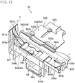
- FIG. 11 is a perspective view illustrating a lower portion of the tape loop forming unit 92 as viewed obliquely from above.
- the lower guide 926 has a pair of sidewalls 926a, 926a which regulates the position of the tape T in the tape width direction and a bottom wall 926b, and thus has the shape of a groove.
- the bottom wall 926b is broader than the width of the tape.
- the pair of sidewalls 926a, 926a are inclined such that the groove increases its width toward the opening end of the groove from the bottom wall 926b (i.e., upward from the bottom wall 926b).
- the bottom wall 926b has a through hole through which a stamp 981 of the stamper 98 (to be described later) passes.
- the first corner guide 929a and the second corner guide 929b are respectively provided at the longitudinal ends of the bottom wall 926b.
- the first corner guide 929a curves the tape T located at the corner formed by the lower guide 926 and the first lateral guide 927.
- the second corner guide 929b curves the tape T located at the corner formed by the lower guide 926 and the second lateral guide 928 (not shown in FIG. 11 ).
- Each of the first and second corner guides 929a and 929b is made up of two plates. Each of the two plates has an edge curved in a concave shape, and the two plates are provided to stand upright on the bottom wall 926b and face each other.
- the lower guide 926 is provided with a displacement mechanism, and is configured to be readily moved in the vertical direction by the displacement mechanism.
- the displacement mechanism also functions as a displacement mechanism for lower clamps 943, 944 which will be described later.
- the first lateral guide 927 extends in the vertical direction at one of longitudinal ends of the lower guide 926 closer to the bundling stacker 4.
- the first lateral guide 927 includes a sidewall 927a and a bottom wall 927b, and thus has the shape of a groove.
- the sidewall 927a regulates the position of the tape T in the tape width direction.
- the bottom wall 927b is broader than the width of the tape.
- the bottom wall 927b is provided with two slits through which the first corner guide 929a passes.
- the second lateral guide 928 extends in the vertical direction at the other longitudinal end of the lower guide 926 closer to the dispense unit 11.
- the second lateral guide 928 is substantially in the shape of a flat plate.
- the second lateral guide 928 is supported to be movable up and down by a support, and is coupled to the lower guide 926 through a link.
- the second lateral guide 928 moves upward or downward as the lower guide 926 moves upward or downward.
- the magnitude of movement of the second lateral guide 928 is amplified by the link.
- the second lateral guide 928 is configured to retreat upward during the transportation of the bundled banknotes B so as not to interfere with the transportation of the bundled banknotes B.
- the third corner guide 929c and the fourth corner guide 929d are provided above the first and second corner guides 929a and 929b at almost the same level as the tape gripping part 921.
- the third corner guide 929c is arranged adjacent to the first lateral guide 927.
- the third corner guide 929c has two plates. Each of the two plates has an edge curved in a concave shape, and the two plates are provided to stand upright on the bottom wall 927b and face each other.
- the fourth corner guide 929d is arranged adjacent to the second lateral guide 928.
- the fourth corner guide 929d is formed of a block having a surface curved in a concave shape. When it is not necessary to distinguish the first to fourth corner guides 929a to 929d from each other, they may be hereinafter referred to as "corner guides 929" collectively.
- the second tape sensor 9211 is configured in the same manner as the banknote sensor 25, and detects the tape T when the light is blocked.
- the receiver of the second tape sensor 9211 is attached to the fourth corner guide 929d as conceptually shown in FIG. 5 .
- the transmitter of the second tape sensor 9211 is arranged such that the light emitted from the transmitter is blocked by the tape T guided along the fourth corner guide 929d. That is, the second tape sensor 9211 detects that the fourth corner guide 929d is guiding the tape T, i.e., the tape loop L has reached a predetermined size, when the light emitted from the transmitter is not received by the receiver.
- the temporary gripping unit 93 temporarily grips the banknotes B transported into the tape loop L by the second transport unit 8.
- the temporary gripping unit 93 is arranged opposite to the second transport unit 8 relative to the tape loop L in the second horizontal direction, i.e., in the tape width direction.
- the temporary gripping unit 93 grips the banknotes B at their portion opposite to the second transport unit 8 relative to the tape loop L.
- the temporary gripping unit 93 includes an upper gripping part 931, a lower gripping part 932, and a vertical displacement mechanism which displaces the upper and lower gripping parts 931 and 932 in the vertical direction.
- the temporary gripping unit 93 grips the banknotes B with the upper and lower gripping parts 931 and 932.
- FIG. 12 is a perspective view illustrating an upper portion of the tape loop forming unit 92 as viewed obliquely from below.
- the upper gripping part 931 includes an upper base plate 933, an upper movable plate 934, and first and second abutting portions 931a, 931b provided for the upper movable plate 934.
- the first and second abutting portions 931a, 931b are arranged side by side in the direction parallel to the shorter edges of the banknotes B.
- the first and second abutting portions 931a and 931b are located at the same level.
- the first and second abutting portions 931a and 931b are made of urethane rubber.
- first and second abutting portions 931a and 931b may be made of rubber or a resin other than the urethane rubber.
- the tape gripping part 921 is arranged between the first and second abutting portions 931a and 931b.
- the upper movable plate 934 is supported by the upper base plate 933 such that the upper movable plate 934 is movable along the width of the tape T.
- the lower gripping part 932 includes, as shown in FIG. 11 , a lower base plate 935, a lower movable plate 936, and first and second abutting portions 932a, 932b provided for the lower movable plate 936.
- the first and second abutting portions 932a, 932b are arranged side by side in the direction parallel to the shorter edges of the banknotes B.
- the first and second abutting portions 932a and 932b are located at the same level.
- the first and second abutting portions 932a, 932b respectively face the first and second abutting portions 931a, 931b of the upper gripping part 931.
- the first and second abutting portions 932a and 932b are made of urethane rubber.
- first and second abutting portions 932a and 932b may be made of rubber or a resin other than the urethane rubber.
- the lower movable plate 936 is supported by the lower base plate 935 such that the lower movable plate 936 is movable along the width of the tape T.
- the upper and lower movable plates 934 and 936 are configured to move in the second horizontal direction synchronously with the movement of the second transport unit 8 while the banknotes are being transported into the large tape loop L2.
- the upper movable plate 934 is supported not only by the upper base plate 933, but also by a vertically extending shaft as well.
- the lower movable plate 936 is also supported not only by the lower base plate 935, but also by a vertically extending shaft as well. Since these shafts extend vertically, the upper and lower movable plates 934 and 936 move up and down along the shafts as the upper and lower gripping parts 931 and 932 move up and down. Thus, the shafts do not interfere with the vertical movement of the upper and lower gripping parts 931 and 932.
- These two shafts form integral parts of a frame. The frame and the shafts are configured to be readily moved by a displacement mechanism in the second horizontal direction.
- the frame and the shafts are allowed by the displacement mechanism to move in the second horizontal direction synchronously with the movement of the second transport unit 8 while the banknotes are being transported into the large tape loop L2. That is to say, when the second transport unit 8 transports the banknotes into the large tape loop L2, the displacement mechanism moves the frame in the second horizontal direction synchronously with the movement of the second transport unit 8. As the frame moves in the second horizontal direction, the upper and lower movable plates 934 and 936 supported by the shafts of the frame also move in the second horizontal direction.
- the clamp 94 presses the banknotes B in the stacking direction when the banknotes B are bundled together with the tape T.
- the clamp 94 presses the vicinity of a portion of the banknotes B to be bundled with the tape T.
- the clamp 94 includes, as shown in FIGS. 10-12 , a pair of upper clamps 941, 942 provided above the banknotes B transported into the tape loop L, a pair of lower clamps 943, 944 provided below the banknotes B, and a displacement mechanism which allows one of the upper clamps 942 and the lower clamps 943, 944 to move up and down.
- the upper clamps 941, 942 are arranged on the respective sides of the tape T in the tape width direction.
- the upper clamp 941 located more distant from the second transport unit 8 is fixed, and is not movable up or down.
- the upper clamp 942 located closer to the second transport unit 8 is configured to be movable up and down.
- the upper fixed clamp 941 includes first and second abutting portions 941a, 941b.
- the first and second abutting portions 941a, 941b are arranged side by side in the direction parallel to the shorter edges of the banknotes B.
- the first and second abutting portions 941a and 941b are located at the same level.
- the first and second abutting portions 941a, 941b are made of urethane rubber.
- the first and second abutting portions 941a, 941b may be made of rubber or resin other than the urethane rubber.
- a portion of the tape gripping part 921 is arranged between the first and second abutting portions 941a and 941b.
- the tape gripping part 921 is located at a lower level than the first and second abutting portions 941a, 941b.
- the upper movable clamp 942 includes first to third abutting portions 942a to 942c.
- the first to third abutting portions 942a to 942c are arranged side by side in the direction parallel to the shorter edges of the banknotes B.
- the third abutting portion 942c is located between the first and second abutting portions 942a and 942b in the direction parallel to the shorter edges of the banknotes B.
- the first and second abutting portions 942a and 942b are located at the same level.
- the third abutting portion 942c is located at a lower level than the first and second abutting portions 942a and 942b.
- the first to third abutting portions 942a to 942c are made of urethane rubber. However, the first to third abutting portions 942a to 942c may be made of any other rubber than the urethane rubber or a resin.
- the upper movable clamp 942 moves up and down between a clamp position where the first and second abutting portions 942a and 942b are level with the first and second abutting portions 941a and 941b of the upper fixed clamp 941, and a retreat position where the third abutting portion 942c is at a higher level than the first and second abutting portions 941a and 941b of the upper fixed clamp 941.
- the third abutting portion 942c is located at substantially the same level as the tape gripping part 921.
- the lower clamps 943, 944 are arranged on the respective sides of the tape T in the tape width direction.
- the lower clamp 943 located more distant from the second transport unit 8 and the lower clamp 944 located closer to the second transport unit 8 are configured in the same manner.
- the lower clamp 943 includes first and second abutting portions 943a, 943b.
- the first and second abutting portions 943a, 943b are arranged side by side in the direction parallel to the shorter edges of the banknotes B.
- the first and second abutting portions 943a and 943b are located at the same level.
- the first and second abutting portions 943a, 943b are made of urethane rubber.
- first and second abutting portions 943a, 943b may be made of any other rubber than the urethane rubber or a resin.
- the first and second abutting portions 943a, 943b respectively face the first and second abutting portions 941a, 941b of the upper fixed clamp 941.
- the lower clamp 944 includes first and second abutting portions 944a, 944b.
- the first and second abutting portions 944a, 944b are arranged side by side in the direction parallel to the shorter edges of the banknotes B.
- the first and second abutting portions 944a and 944b are located at the same level, and also at the same level as the first and second abutting portions 943a and 943b of the lower clamp 943.
- the first and second abutting portions 944a, 944b are made of urethane rubber. However, the first and second abutting portions 944a, 944b may be made of any other rubber than the urethane rubber or a resin. The first and second abutting portions 944a, 944b respectively face the first and second abutting portions 942a, 942b of the upper movable clamp 942.
- the lower clamps 943, 944 form an integral part of the lower guide 926 of the guide 925, and move up and down together with the lower guide 926.
- the displacement mechanism which displaces the lower clamps 943, 944 in the vertical direction also functions as the displacement mechanism for the lower guide 926.
- the heater 95 bonds together portions of the tape T wound around the banknotes B.
- the heater 95 heat-seals such portions of the tape T.
- the cutter 96 cuts a portion of the tape T not wound around the banknotes B, that is, an excessive portion of the tape T that has not been used to bundle the banknotes B together with the tape T.
- the tip of the cutter 96 is provided with a serrated cutting blade.
- the heater 95 and the cutter 96 are configured as a unit, and is arranged opposite to the stamper 98 relative to the banknotes B brought into the tape loop L, that is, opposite to the stamper 98 in the stacking direction of the banknotes B, i.e., above the tape gripping part 921.
- the heater 95 heat-seals the tape T on the tape gripping part 921.
- the cutter 96 cuts the tape T on the tape gripping part 921.
- the printer 97 is arranged in the tape transport unit 912 as shown in FIG. 5 .
- the printer 97 includes a print head which prints characters on the tape T transported by the tape transport unit 912.
- the printer 97 prints, for example, information about the banknotes B to be bundled (e.g., denomination, date, and/or serial number) on the tape T.
- the print made by the printer 97 is shifted in the tape width direction from a portion on which a seal will be stamped by the stamper 98 so that the print does not overlap with the seal stamped by the stamper 98.
- the stamper 98 stamps a seal on the tape T wound around the banknotes B compressed by the clamp 94.
- the stamper 98 stamps a seal related to the banknotes B to be bundled (e.g., a seal of a financial institution, a seal indicating the kind of the banknotes such as fit or unfit notes) on the tape T.
- the stamper 98 is arranged opposite to the heater 95 and the cutter 96 relative to the banknotes B brought into the tape loop L, in particular, opposite to the heater 95 and the cutter 96 in the stacking direction of the banknotes B.
- the stamper 98 includes a stamp 981 and a displacement mechanism (not shown) which displaces the stamp 981 in the vertical direction.
- the stamp 981 stamps a seal on the tape T wound around the banknotes B in the stacking direction of the banknotes B.
- the stamper 98 forms an integral part of the lower guide 926, and moves up and down along with the lower guide 926 that is moving up and down.
- FIGS. 13A-13C show how the respective members operate until the banknotes B transported into the large tape loop L2 are gripped by the temporary gripping unit 93 when the banknotes B are viewed in the thickness direction.
- FIG. 13A shows a state just before the banknotes B are extracted from the bundling stacker 4.
- FIG. 13B shows a state just before the banknotes B are transported into the large tape loop L2.
- FIG. 13C shows a state where the banknotes B are gripped by the temporary gripping unit 93.
- FIGS. 13A-13C show how the respective members operate until the banknotes B transported into the large tape loop L2 are gripped by the temporary gripping unit 93 when the banknotes B are viewed in the thickness direction.
- FIG. 13A shows a state just before the banknotes B are extracted from the bundling stacker 4.
- FIG. 13B shows a state just before the banknotes B are transported into the large tape loop L2.
- FIG. 13C shows a state where the banknote
- FIGS. 15A-15C show how the respective members operate until the banknotes B are gripped again by the gripper 81 and the tape T is wound around the banknotes B as viewed in the thickness direction of the banknotes B.
- FIG. 14A shows a state where the gripper 18 grips the banknotes B again
- FIG. 14B shows a state where the clamp 94 presses the banknotes B
- FIG. 14C shows a state where the tape T is wound around the banknotes B.
- FIGS. 15A-15C show how the respective members operate until the banknotes B are transported to the dispense unit 11 as viewed in the thickness direction of the banknotes B.
- FIG. 15A shows a state where the bundled banknotes B are removed in the second horizontal direction
- FIG. 15B shows a state where the third transport unit 10 grips the bundled banknotes B
- FIG. 15C shows a state where the third transport unit 10 transports the bundled banknotes B to the dispense unit 11.
- FIG. 16 illustrates a schematic layout for the second handling section 127 as viewed from above.
- the upper gripping part 931, the upper fixed clamp 941, and the upper movable clamp 942 are not shown.
- portions of the lower gripping part 932 and the lower clamps 943, 944 in contact with the banknotes B are hatched.
- the second transport unit 8 transports the banknotes B from the bundling stacker 4 to the bundling unit 9.
- the gripper 81 of the second transport unit 8 grips the banknotes B in the first bundling stacker 4A.
- the second transport unit 8 removes the gripped banknotes B from the first bundling stacker 4A in the first horizontal direction as shown in FIG. 13A , and moves the banknotes B as they are in the first horizontal direction until the position of the banknotes B agrees with the position of the tape loop L in the first horizontal direction.
- This first horizontal direction corresponds with a first transport direction.
- the second transport unit 8 displaces the banknotes B vertically to a level at which the banknotes B are going to be transported into the tape loop L.
- the control unit 120 forms a tape loop L while the second transport unit 8 is transporting the banknotes B from the bundling stacker 4 to the second position.
- the second transport unit 8 moves the banknotes B in the second horizontal direction to bring the banknotes B into the large tape loop L2.
- the temporary gripping unit 93 also moves in the second horizontal direction as the second transport unit 8 moves. Specifically, in the second horizontal direction, the temporary gripping unit 93 moves in the same direction as the second transport unit 8. The magnitude of movement of the temporary gripping unit 93 corresponds with that of the second transport unit 8. This second horizontal direction corresponds with a second transport direction.
- the temporary gripping unit 93 grips the banknotes B as shown in FIG. 13C .
- the gripper 81 of the second transport unit 8 releases the banknotes B and moves in the second horizontal direction opposite to the direction in which the banknotes B were brought into the large tape loop L2. Then, as shown in FIG. 14A , the gripper 81 grips the banknotes B again at their portion other than a portion to be bundled (a portion around which the tape T will be wound later in the process).
- the clamp 94 presses the banknotes B in the stacking direction, i.e., from over and from under the banknotes B in the vertical direction as shown in FIG. 14B .
- the banknotes B are compressed vertically by the upper clamps 941, 942 and the lower clamps 943, 944.
- the gripper 81 and the temporary gripping unit 93 no longer grip the banknotes B.
- the heater 95 bonds together portions of the tape T, and the cutter 96 cuts off the tape T.
- the stamper 98 stamps a seal on the tape T.
- the gripper 81 grips the bundled banknotes B. Then, the lower clamps 943, 944 move downward to release the pressure applied by the clamp 94. In the meantime, the lower gripping part 932 of the temporary gripping unit 93 also moves slightly downward. In addition, the upper movable clamp 942 moves upward. Thereafter, the second transport unit 8 transports the bundled banknotes B to a predetermined extent in the second horizontal direction and to the opposite direction from the direction of transportation of the banknotes into the large tape loop L2 as shown in FIG. 15A .
- the tape gripping part 921 grips a tip end of the tape T, and the tape gripping part 921 is caught in a gap between the tape T and the bundled banknotes B.
- the second transport unit 8 draws the bundled banknotes B in the second horizontal direction until the tape gripping part 921 is withdrawn from the gap between the tape T and the banknotes B.
- the gripper 81 releases its grip on the bundled banknotes B.
- the third transport unit 10 grips the bundled banknotes B in turn.
- the lower clamps 943, 944 move downward to the predetermined level. This level corresponds to the level of the dispense unit 11.
- the lower gripping part 932 also moves downward to the same level as the lower clamps 943, 944.
- the second transport unit 8 displaces the bundled banknotes B to the level of the lower clamps 943, 944, and then releases its grip on the gripper 81.
- the lower arm 81b is level with the lower clamps 943, 944.
- the bundled banknotes B are now placed on the lower arm 81b and the lower clamps 943, 944.
- the third transport unit 10 moves in the first horizontal direction from the bundling stacker 4 side toward the bundled banknotes B.
- the gap between the upper and lower gripping parts 101 and 102 of the third transport unit 10 decreases as the third transport unit 10 approaches the bundled banknotes B.
- the third transport unit 10 will be gripping the bundled banknotes B.
- the third transport unit 10 transports the bundled banknotes B in the first horizontal direction toward the dispense unit 11.
- the lower arm 81b and lower clamps 943, 944 of the second transport unit 8 support the bundled banknotes B from under them, and function as a guide when the bundled banknotes B are transported to the dispense unit 11.
- the third transport unit 10 gradually releases its grip on the bundled banknotes B.
- the bundled banknotes B are pushed toward the dispense unit 11 by the third transport unit 10 as shown in FIG. 15C .
- the bundling unit 9 is slightly displaced from the first horizontal direction in which the second transport unit 8 removes the banknotes B from the bundling stacker 4 as viewed in a direction perpendicular to a horizontal plane. That is, the bundling unit 9 is slightly displaced from a straight line extending from the bundling stacker 4 in the first horizontal direction.
- the second and third transport units 8 and 10 remove the banknotes B from the bundling stacker 4 in the first horizontal direction, transport the banknotes B in the second horizontal direction intersecting with the first horizontal direction to bring them into the bundling unit 9, carry the bundled banknotes B out of the bundling unit 9 in the opposite direction from when the banknotes B were brought into the bundling unit 9 in the second horizontal direction, and then transport the banknotes B in the same direction as when the banknotes B were removed from the bundling stacker 4 in the first horizontal direction. Thereafter, the third transport unit 10 transports the bundled banknotes B to the dispense unit 11.
- a transportation space is provided in the housing 12 as shown in FIG. 16 to ensure a substantially T-shaped transport path which goes in the first horizontal direction from the bundling stacker 4, goes one way in the second horizontal direction, goes the other way in the second horizontal direction, and then returns to the first horizontal direction again.
- This arrangement of the bundling stacker 4, the bundling unit 9, and the dispense unit 11 ensures such a transportation space, thus allowing a tech person to do maintenance of this apparatus efficiently using this transportation space during maintenance.
- FIG. 17 is a perspective view showing the dispense unit with the housing partially cut away and illustrating a receiving state where the dispense unit is ready to receive the bundled banknotes B.
- FIG. 18 is a perspective view showing the dispense unit with the housing partially cut away and illustrating a dispensing state where the dispense unit is ready to dispense the bundled banknotes B.
- FIG. 19 is a perspective view of principal parts extracted from the dispense unit, illustrating the receiving state.
- FIG. 20 is a perspective view of principal parts extracted from the dispense unit, illustrating the dispensing state.
- FIG. 21 is a front view of principal parts extracted from the dispense unit, illustrating the receiving state.
- FIG. 22 is a front view of principal parts extracted from the dispense unit, illustrating the dispensing state.
- the dispense unit 11 includes a slider 112 which receives the bundled banknotes B at a receiving position and allows the bundled banknotes B to slide laterally to dispense the bundled banknotes B at a dispensing position, a base 113 which supports the slider 112 in a slidable state, a driver 114 which drives the slider 112, a first sensor 117 (see FIGS. 19 and 20 ) which detects the presence or absence of the banknotes B on the slider 112 at the receiving position, and a second sensor 118 (see FIGS. 19 and 20 ) which detects the presence or absence of the banknotes B on the slider 112 at the dispensing position.
- the receiving position is a position at which the banknotes B are received from the third transport unit 10, and agrees with the position of the third transport unit 10 in the second horizontal direction.
- the receiving position is located above the hopper unit 2.
- the dispensing position is a position at which the banknotes B are dispensed to the dispense port 111, and agrees with the position of the dispense port 111 in the second horizontal direction.
- the dispensing position is slightly displaced laterally from the position above the hopper unit 2.
- the base 113 is made of sheet metal.
- the base 113 includes a guide pole 113a (see FIGS. 18 and 20 ) which guides the slider 112, and a cam plate 113b which guides the slider 112.
- the guide pole 113a extends in the second horizontal direction.
- the cam plate 113b extends in the second horizontal direction, and includes a rectilinear groove 113c and a cam groove 113d.
- the rectilinear groove 113c extends in the second horizontal direction.
- the cam groove 113d extends mostly in the second horizontal direction, and one end thereof closer to the dispensing position extends obliquely downward.
- the base 113 includes the driver 114.
- the driver 114 includes a driving motor 114a, a first gear 114b coupled to the driving motor 114a, a second gear 114c engaging with the first gear 114b, and a third gear 114d rotating synchronously with the second gear 114c.
- the base 113 includes, as shown in FIGS. 19 and 20 , a transmitter for the first sensor 117 and a transmitter for the second sensor 118.
- the transmitters for the first and second sensors 117 and 118 are arranged at different positions in the second horizontal direction.
- the transmitter for the first sensor 117 is arranged such that light emitted from the transmitter is blocked by the banknotes B on the slider 112 located at the receiving position.
- the transmitter for the second sensor 118 is arranged such that light emitted from the transmitter is blocked by the banknotes B on the slider 112 located at the dispensing position.
- the slider 112 includes a transport unit 115 which transports the banknotes B, and a receiver 116 which receives the banknotes B to prevent the banknotes B from falling.
- the transport unit 115 includes a supporting portion 115a which supports the banknotes B, a hanging portion 115b (see FIGS. 19 and 20 ) which is bent and extends downward from the supporting portion 115a, a locking part 115c which comes into contact with one of shorter edges of the banknotes B during transportation of the banknotes B, a bushing 115d into which the guide pole 113a is inserted, a rack 115e provided for the hanging portion 115b and engaging with the driver 114, and a first bearing 115f provided for the hanging portion 115b and engaging with the rectilinear groove 113c.
- the supporting portion 115a is made of substantially rectangular sheet metal, and inclined relative to the horizontal plane such that one of its longer sides closer to the third transport unit 10 is located at a higher level than the other side.
- the hanging portion 115b is provided at the lower one of the longer sides of the supporting portion 115a.
- the locking part 115c is provided at one of the shorter sides closer to the receiving position.
- the supporting portion 115a includes a first hole 115g through which the light emitted from the transmitter of the first sensor 117 passes, and a second hole 115h through which the light emitted from the transmitter of the second sensor 118 passes.
- the first hole 115g is arranged such that the light emitted from the transmitter of the first sensor 117 can pass through the first hole 115g when the transport unit 115 is located at the receiving position.
- the second hole 115h is arranged such that the light emitted from the transmitter of the second sensor 118 can pass through the second hole 115h when the transport unit 115 is located at the dispensing position.
- the hanging portion 115b is arranged to face the cam plate 113b.
- the first bearing 115f is provided on one surface of the hanging portion 115b facing toward the cam plate 113b.
- the rack 115e is provided on the other surface of the hanging portion 115b facing away from the cam plate 113b.
- the rack 115e extends in the second horizontal direction.
- the rack 115e engages with the third gear 114d of the driver 114.
- the hanging portion 115b includes an engagement groove 115i extending in a direction perpendicular to the second horizontal direction to catch the receiver 116 (see FIGS. 19 , 20 and 22 ).
- the engagement groove 115i extends approximately vertically.
- the receiver 116 is made of sheet metal.
- the receiver 116 includes a second bearing 116a which engages with the cam groove 113d, and an engagement pin (not shown) which engages with the engagement groove 115i.
- the engagement pin engages with the engagement groove 115i, thereby having the receiver 116 attached to the hanging portion 115b of the transport unit 115.
- the receiver 116 moves together with the transport unit 115.
- the receiver 116 is movable along the engagement groove 115i relative to the transport unit 115.
- the second bearing 116a is provided on the other surface of the receiver 116 opposite from the engagement pin.
- the third transport unit 10 transports the bundled banknotes B to the dispense unit 11.
- the slider 112 is located at the receiving position as shown in FIG. 17 .
- the second bearing 116a is located at one end of the cam groove 113d closer to the receiving position as shown in FIGS. 19 and 21 .
- the receiver 116 is now protruding from the surface of the supporting portion 115a (i.e., in the receiving state).
- the third transport unit 10 pushes the bundled banknotes B toward the slider 112.
- the bundled banknotes B slide down the surface of the supporting portion 115a, which is inclined, and are received by the receiver 116.
- the driving motor 114a is actuated to drive the transport unit 115 via the gear train and the rack 115e.
- the transport unit 115 is guided by the guide pole 113a and the rectilinear groove 113c to move in the second horizontal direction toward the dispensing position.
- the receiver 116 also moves in the second horizontal direction together with the transport unit 115. However, the receiver 116 is guided by the cam groove 113d via the second bearing 116a. Since the end of the cam groove 113d closer to the dispensing position extends obliquely downward and the receiver 116 is movable relative to the transport unit 115 along the engagement groove 115i, the receiver 116 moves downward as it approaches the dispensing position. That is, the degree of protrusion of the receiver 116 from the supporting portion 115a starts to decrease as the slider 112 approaches the dispensing position. Once the receiver 116 has reached the dispensing position, the receiver 116 will no longer protrude from the surface of the supporting portion 115a (i.e., in the released state) as shown in FIGS. 20 and 22 .
- the bundled banknotes B at the dispensing position are no longer supported, and slide down the surface of the supporting portion 115a as shown in FIG. 18 to be dispensed from the dispense port 111.
- the transport unit 115 returns to the receiving position to get ready to receive the bundled banknotes B coming next, the receiver 116 is guided along the cam groove 113d to recover the receiving state.
- the banknotes B stacked in the bundling stacker 4 are bundled in the bundling unit 9, and then dispensed from the dispense port 111.
- FIG. 23 is a perspective view of the banknote handling apparatus 100 when the banknotes B have been taken in.
- the bundling stacker 4 still contains the banknotes B which are short of the bundling number, while the non-bundling stacker 5 and the reject stacker 6 respectively have the banknotes B to be stacked therein. Therefore, when the intake of the banknotes B is finished, the control unit 120 instructs the touch panel 17 to display an alert that says the banknotes B should be removed. At the same time, if the banknotes B are stacked in the bundling stacker 4, the control unit 120 unlocks the door 46 of the bundling stacker 4 to open the door 46, and turns the light ON in the bundling stacker 4.
- the other bundling stacker 4 neither opens its door 46, nor turns its light ON. If the banknotes B are stacked in the non-bundling stacker 5, the control unit 120 activates the pushing mechanism 54 of the non-bundling stacker 5 to push out the banknotes B, and turns the light ON in the non-bundling stacker 5. If there are some banknotes B stacked in the reject stacker 6, although no banknotes B are stacked in the reject stacker 6 shown in FIG. 23 , the control unit 120 turns the light ON in the reject stacker 6.
- the operator is notified of the presence of the banknotes B in the bundling stacker 4 when the door 46 opens automatically and the light turns ON. Further, the operator is notified of the presence of the banknotes B in the non-bundling stacker 5 when the banknotes B are pushed out of the non-bundling stacker 5 and the light turns ON. In addition, the operator is notified of the presence of the banknotes B in the reject stacker 6 when the light turns ON.
- opening the door 46 of the bundling stacker 4, pushing the banknotes out of the non-bundling stacker 5, or turning the light ON in the stacker may visually prompt the operator to remove the banknotes B.
- the stage 41 and the guide 42 are operated in a predetermined fashion. Specifically, the control unit 120 moves the stage 41 to the lowermost position. At the same time, the control unit 120 moves the guide 42 toward the frontend in the transport direction from the state where the banknotes B were stacked. Thus, a gap is created between the guide 42 and the banknotes B. This may ensure a space above the banknotes B and in front of the banknotes B in the transport direction, thereby facilitating the removal of the banknotes B.
- the apparatus sees whether or not there are any banknotes B still left in the bundling stacker 4. Specifically, when the door 46 opens, the stage 41 is located at the lowermost position as described above. Thus, the control unit 120 moves the stage 41 upward to return the stage 41 to the initial position. Then, the control unit 120 checks in this state whether or not the first or second banknote sensor 411 and 412 has detected any banknotes B. If the first or second banknote sensor 411 or 412 has detected any banknotes B, the control unit 120 determines that some banknotes B are left in the bundling stacker 4. Then, the control unit 120 moves the stage 41 to the lowermost position, and opens the door 46 again.
- This configuration may substantially prevent the banknotes B from being left in the bundling stacker 4.
- FIGS. 24-26 are perspective views illustrating three different types of positioning units 47.
- FIGS. 24-26 show a state where the door 46 is opened to expose the positioning unit 47.
- first positioning unit 47A a second positioning unit 47B
- third positioning unit 47C a third positioning unit 47C
- the first positioning unit 47A is attached to the inner side of the door 46 as shown in FIG. 24 .
- the second positioning unit 47B is attached to the first positioning unit 47A as shown in FIG. 25 .
- the third positioning unit 47C is also attached to the first positioning unit 47A as shown in FIG. 26 .
- FIG. 27 shows a general plan view illustrating the bundling stacker with the first positioning unit 47A attached thereto.
- FIG. 28 shows a general plan view illustrating the bundling stacker with the third positioning unit 47C attached thereto. In FIGS. 27 and 28 , some of the components of the bundling stacker are not shown.
- a general plan view illustrating the bundling stacker with the second positioning unit 47B attached thereto is shown in FIG. 9 .
- replacement of the positioning unit 47 changes the alignment position P at which the first edge b1 of the banknotes B should be located.
- first positioning unit 47A since the first positioning unit 47A is directly attached to the door 46, its alignment position P is closest to the door 46 in the direction parallel to the longer edges of the banknotes B, i.e., farthest away from the alignment mechanism 49.
- the second positioning unit 47B is attached to the first positioning unit 47A, and thus, its alignment position P is farther away from the door 46, and is closer to the alignment mechanism 49, than the alignment position P defined by the first positioning unit 47A in the direction parallel to the longer edges of the banknotes B.
- the third positioning unit 47C is attached to the first positioning unit 47A, and is thicker than the second positioning unit 47B, and thus, its alignment position P is farthest away from the door 46, and is closest to the alignment mechanism 49, in the direction parallel to the longer edges of the banknotes B.
- the positioning unit 47 is replaced depending on the dimension of the longer edges of the banknotes B.
- the dimension of the longer edges of the banknotes B varies according to the kind of the banknotes B.
- the first edge b1 of the banknotes B may be pushed against the positioning unit 47 by adjusting the magnitude of movement of the arm 49a.
- mere adjustment of the magnitude of movement of the arm 49a would require the banknotes B having relatively short longer edges to travel a longer distance since they have fallen onto the stage 41 until their first edge b1 comes into contact with the positioning unit 47.
- the increased traveling distance of the banknotes B would increase the chances of fluttering of the banknotes B during their travel.
- replacement of the positioning unit 47 depending on the dimension of the longer edges of the banknotes B may reduce the distance for the banknotes B to travel until their first edge b1 comes into contact with the positioning unit 47.
- the magnitude of movement of the arm 49a may also be reduced. Specifically, if banknotes B, of which the dimension of the longer edges falls within a first range, namely, equal to or smaller than X1 and equal to or larger than X2, are going to be stacked, the first positioning unit 47A is attached, and the dimensional variation within the first range is addressed by adjusting the magnitude of movement of the arm 49a.
- banknotes B of which the dimension of the longer edges falls within a second range, namely, smaller than X2 and equal to or larger than X3, are going to be stacked, the second positioning unit 47B is attached, and the dimensional variation within the second range is addressed by adjusting the magnitude of movement of the arm 49a.
- the third positioning unit 47C is attached, and the dimensional variation within the third range is addressed by adjusting the magnitude of movement of the arm 49a.
- the control unit 120 stores in advance the dimensions of the banknotes B to be stacked in the bundling stacker 4 and the type of the positioning unit 47 being attached.
- the control unit 120 adjusts the magnitude of movement of the arm 49a according to the dimension of the longer edges of the banknotes B stacked in the bundling stacker 4 and the alignment position P of the positioning unit 47 being attached.
- the dimension of the longer edges of the banknotes B greatly varies depending on country in which the banknotes are distributed.
- the variation in the dimension of the longer edges of the banknotes B distributed in the same country may be addressed by merely adjusting the range of movement of the arm 49a.
- banknotes B of a different country have a greatly different dimension of their longer edges, and such a dimensional variation cannot be addressed by merely adjusting the range of movement of the arm 49a. That is to say, in one exemplary usage, the type of the positioning unit 47 may be changed depending on the country in which the banknote handling apparatus 100 is used. Then, there will be no need to provide multiple different banknote handling apparatuses 100 for respective countries, but a common banknote handling apparatus 100 may easily be used in various different countries just by changing the positioning units 47.
- the replacement of the positioning unit 47 works not only when the country changes.
- the positioning unit 47 may also be replaced depending on the dimension of the longer edges of the banknotes B to be stacked in the bundling stacker 4 during the use of the banknote handling apparatus 100.
- adjusting the magnitude of movement of the arm 49a of the alignment mechanism 49 according to the dimension of the longer edges of the banknotes B, as well as replacing the positioning unit 47 allows this apparatus to handle a broader variety of banknotes B while reducing the number of the positioning units 47 to provide.
- the banknotes B of which the dimension of their longer edges falls within the predetermined range, may be handled only by adjusting the magnitude of movement of the arm 49a without replacing the positioning unit 47.
- a broader variety of the banknotes B may be positioned by a single type of positioning unit 47.
- the positioning unit 47 is provided for the door 46 which is attached in a freely rotatable state to one side of the frame 46a. When opened, the door 46 exposes the positioning unit 47 outside the bundling stacker 4. That is, opening the door 46 facilitates the replacement of the positioning unit 47.
- the second positioning unit 47B is attached to the first positioning unit 47A
- the third positioning unit 47C is attached to the first positioning unit 47A.
- the second and third positioning units 47B and 47C may directly be attached to the door 46.
- the second and third positioning units 47B and 47C may each have their thickness defined by their alignment positions P.
- the banknote handling apparatus 100 includes a bundling stacker 4 which piles and stacks banknotes B.
- the bundling stacker 4 includes a positioning unit 47 configured to face a first edge b1, which is one of the edges of the banknotes B stacked, and place the first edge b1 at a predetermined alignment position P, and a pushing mechanism 49 which pushes a third edge b3, which is another one of the edges of the banknotes B opposite from the first edge b1, to bring the first edge b1 into contact with the positioning unit 47.
- the positioning unit 47 is configured to be replaceable such that replacement of the positioning unit 47 changes the alignment position P.
- a paper sheet processing device which takes in, and bundles, loose paper sheets, and dispenses the paper sheets bundled (see, e.g., Japanese Unexamined Patent Publication No. 2002-197509 ).
- the components inside the paper sheet processing device may be arranged in various ways.
- the components of the paper sheet processing device may be arranged such that the paper sheets are taken in the housing from a taking-in unit, bundled in the housing, and the bundled paper sheets are dispensed above the taking-in unit due to the limitation on the layout. Such an arrangement may be adopted if the paper sheet processing device needs to be downsized.
- the taking-in unit since the paper sheets are placed on the taking-in unit before the intake, the taking-in unit is required to have some space around it. If the paper sheets are dispensed above the taking-in unit, there is no space for the paper sheets to fall downward. Thus, if the paper sheets are accumulated at the space above the taking-in unit, the paper sheet processing device needs to be expanded in vertical dimension.
- the paper sheet processing device disclosed herein is configured in the following manner.
- the first sensor which detects the presence or absence of the paper sheets at the receiving position and the second sensor which detects the presence or absence of the paper sheets at the dispensing position are provided independently of each other.
- an opening through which the light passes needs to be cut through the transport unit because each sensor detects the presence or absence of the paper sheets using light transmitted and received through the transport unit. If only one opening is cut through the transport unit, the first sensor needs to be arranged such that the light emitted passes through the opening of the transport unit when the transport unit is located at the receiving position, while the second sensor needs to be arranged such that the light emitted passes through the opening of the transport unit when the transport unit is located at the dispensing position.
- the transport unit includes separately a first opening which allows the light from the first sensor to pass through when the transport unit is located at the receiving position, and a second opening which allows the light from the second sensor to pass through when the transport unit is located at the dispensing position.
- the positions of the first and second sensors may be determined as appropriate with respect to the first and second openings, respectively.
- the first sensor may be positioned with respect to the first opening irrespective of the second sensor or the second opening.
- the second sensor may be positioned with respect to the second opening irrespective of the first sensor or the first opening.
- a portion of the transport unit to contact with the banknotes B is made of rubber to reduce the chances of scattering of the banknotes B during transportation.
- a paper sheet processing device which takes the paper sheets in, and handles them in a predetermined manner.
- a paper sheet processing device described in Japanese Unexamined Patent Publication No. 2002-197509 counts the paper sheets taken in, temporarily stacks the counted paper sheets in a stacking unit, and bundles the stacked paper sheets on a predetermined number basis in a bundling unit. At this time, the paper sheets stacked in the stacking unit are transported by a transport unit to the bundling unit.
- a paper sheet processing device is configured such that the paper sheets are transported by the transport unit just like the above-described paper sheet processing device does, the paper sheets may come loose during transportation. As a result, the paper sheets may be scattered inside the device, which complicates a subsequent recovery operation.
- the paper sheet processing device disclosed herein is configured in the following manner.
- the abutting portion of the clamp is also at least partially made of rubber or a resin.
- the chances of scattering of the paper sheets during the bundling may be reduced.
- the arrangement of the bundling stacker 4, the bundling unit 9, and the dispense unit 11 and transport paths of the banknotes B between these members have been modified in this apparatus 100.
- Japanese Unexamined Patent Publication No. 2002-197509 discloses a paper sheet processing device which takes in, and bundles, loose paper sheets, and dispenses the paper sheets bundled.
- loose paper sheets are taken in the device from the top of the device, and the paper sheets bundled are dispensed from the bottom of the device.
- the paper sheets placed on a taking-in unit are taken in in a direction parallel to their shorter edges. Then, the paper sheets, with their shorter edges agreeing with their traveling direction, are sequentially transported to the stacking unit, the bundling unit, and the dispense port.
- any type of device requires maintenance. To do the maintenance, the device needs to be uncovered so that maintenance work is performed on the components inside the device. Taking such maintenance into account, it is recommended that space of a certain size be present inside the device. However, the provision of such space is often difficult from the standpoint of downsizing of the device. Also in the above-described paper sheet processing device, a transport path through which the paper sheets are transported from the taking-in unit to the stacking unit, a transportation mechanism for transporting the paper sheets from the stacking unit to the bundling unit, a transport unit for transporting the paper sheets from the bundling unit to the dispense port, and other components are arranged densely. Thus, almost no space is left in the device for the maintenance.
- the paper sheet processing device disclosed herein is configured in the following manner.
- the paper sheets are transported into the tape loop in the bundling unit.
- This configuration in which the paper sheets are transported into the tape loop fits very well with the configuration in which the paper sheets traveling in the first transport direction is allowed to turn to the second transport direction to be transported into the bundling unit, go the other way around in the second transport direction, and then travel in the first transport direction again.
- the first transport direction agrees with the direction of winding the tape around the paper sheets (e.g., if the paper sheets are transported in the direction parallel to their shorter edges, and the tape is wound around the paper sheets in the direction parallel to their shorter edges)
- the above-described combination of the configurations enables smooth transportation of the paper sheets and smooth winding of the tape.
- the transportation space may be ensured without placing the bundling unit at a position relative to the stacking unit in the first transport direction.
- Embodiments have just been described as examples of the technique disclosed in the present application. However, the present disclosure is not limited to those exemplary embodiments, but is also applicable to other embodiments which are altered or substituted, to which other features are added, or from which some features are omitted, as needed. Optionally, the components described in those embodiments may be combined to create a new embodiment.
- the components illustrated on the accompanying drawings and described in the detailed description include not only essential components that need to be used to overcome the problem, but also other unessential components that do not have to be used to overcome the problem but that are illustrated or mentioned there just for the sake of showing a typical example of the technique. Therefore, such unessential components should not be taken for essential ones, simply because such unessential components are illustrated in the drawings or mentioned in the detailed description.
- the banknote handling apparatus 100 has been described as an example of the paper sheet processing device.
- the paper sheet processing device is not limited to the banknote handling apparatus 100.
- recognition, sorting, and stacking of the paper sheets may be performed by a different apparatus, and the paper sheet processing device may only perform the processing of transporting loose paper sheets, stacking the paper sheets in the stacking unit, and then transporting the paper sheets stacked in the stacking unit to a different place using the transport unit.
- banknotes are supposed to be used as exemplary paper sheets.
- the paper sheets do not have to be banknotes, and may be vouchers such as gift certificates.
- the banknote handling apparatus 100 described above is merely an example, and the present disclosure is not limited thereto.
- the banknote handling apparatus 100 described above is provided with two bundling stackers 4, two non-bundling stackers 5, and a single reject stacker 6.
- the numbers of these stackers are just an example and not limiting.
- one bundling stacker 4 or three or more bundling stackers 4 may be provided.
- One non-bundling stacker 5 or three or more non-bundling stackers 5 may be provided.
- Two or more reject stackers 6 may be provided.
- the non-bundling stackers 5 and the reject stacker 6 may even be omitted.
- the inlet 24, the dispense port 111, and the reject outlet 63 are cut through the first side surface 123, while the first and second outlets 413 and 53 are cut through, and the touch panel 17 is provided on, the second side surface 124.
- this arrangement is merely an example.
- the arrangement of the components of the banknote handling apparatus 100 is also merely an example, and various other arrangements may be adopted as well.
- the dispense unit 11 may be provided on the opposite side surface of the housing 12 from the first side surface 123, and the bundling stacker 4 may be provided closer to the first side surface 123.
- the banknote handling apparatus 100 is supposed to perform a single kind banknote bundling process, but this is only a non-limiting exemplary embodiment of the present disclosure.
- the banknote handling apparatus 100 may perform a multiple kind banknote bundling process, in which banknotes of multiple different kinds are supposed to be bundled separately, the two bundling stackers 4 are supposed to stack banknotes of different kinds, and a predetermined number of banknotes stacked in each of the bundling stackers 4 are bundled by the bundling unit 9. That is, the first and second bundling stackers 4A and 4B may stack the banknotes of mutually different kinds.
- the banknote handling apparatus 100 may perform divisional processing in which the banknotes B are divided into multiple groups, each consisting of a predetermined number of banknotes, without bundling them. That is, the banknote handling apparatus 100 does not need to include the bundling unit 9.
- the divisional processing just like the single kind banknote bundling process, loose banknotes B are placed on the hopper unit 2. Then, the banknotes B are taken in through the inlet 24, recognized by the recognition unit 3, and transported to an appropriate stacker, just like in the single kind banknote bundling process.
- the control unit 120 unlocks the locking mechanism 46c of the bundling stacker 4, and displays an alert on the touch panel 17 that says the predetermined number of banknotes B have been stacked in the bundling stacker 4. In response, the operator opens the door 46 to remove the banknotes B stacked in the bundling stacker 4. When the number of banknotes B stacked in one of the bundling stackers 4 reaches a predetermined number, the control unit 120 transports the remaining banknotes to the other bundling stacker 4.
- the control unit 120 unlocks the locking mechanism 46c of the other bundling stacker 4, and displays an alert on the touch panel 17 that says the predetermined number of banknotes B have been stacked in the bundling stacker 4 in the same manner as described above. The operator then opens the door 46 and removes the banknotes B stacked in the bundling stacker 4.
- the banknote handling apparatus 100 handles loose banknotes including banknotes of multiple different denominations, but this is only a non-limiting exemplary embodiment of the present disclosure.
- the banknote handling apparatus 100 may be configured to handle banknotes of a predetermined single denomination.
- the kind of the banknotes to be stacked in each stacker is determined in advance, but this is only a non-limiting exemplary embodiment of the present disclosure.
- the kind of banknotes to be assigned to respective stackers may be determined in the order of recognition of the banknotes by the recognition unit 3 since the banknotes started to be taken in the banknote handling apparatus 100.
- the first bundling stacker 4A may stack a kind of banknotes B recognized first by the recognition unit 3
- the second bundling stacker 4B may stack a kind of banknotes B recognized second by the recognition unit 3
- the first non-bundling stacker 5A may stack a kind of banknotes B recognized third by the recognition unit 3
- the second non-bundling stacker 5B may stack a kind of banknotes B recognized fourth by the recognition unit 3.
- the banknotes B are transported in a direction parallel to their shorter edges, i.e., with the direction parallel to their shorter edges agreeing with the transport direction, but this is only a non-limiting exemplary embodiment of the present disclosure.
- the banknotes B may be transported in a direction parallel to their longer edges, i.e., with the direction parallel to their longer edges agreeing with the transport direction.
- the transport direction may be changed during the transportation.
- the banknotes B are aligned in the bundling stacker 4 with their first edge b1 in contact with the positioning unit 47, but this is only a non-limiting exemplary embodiment of the present disclosure.
- the second or fourth edge b2 or b4 which is the longer edge of the banknotes B, may be in contact with the positioning unit 47.
- the positioning unit 47 may be replaced in accordance with the dimension of the shorter edges of the banknotes B.
- the banknotes B are stacked in the vertical direction in the bundling stacker 4, and the stage 41 is configured to move vertically, but this is only a non-limiting exemplary embodiment of the present disclosure.
- the surface 41b of the stage 41 may be inclined relative to the vertical direction
- the banknotes B may be stacked in the direction inclined relative to the vertical direction
- the stage 41 may be configured to move in the direction inclined relative to the vertical direction.
- first catching grooves 48, 48, ... of the positioning unit 47 may be omitted.
- the abutting portions 81c, 81d, 101a, and 102a, the first and second abutting portions 931a and 931b, the first and second abutting portions 932a and 932b, the first and second abutting portions 941a and 941b, the first to third abutting portions 942a to 942c, the first and second abutting portions 943a and 943b, and the first and second abutting portions 944a and 944b are made of urethane rubber, but this is only a non-limiting exemplary embodiment of the present disclosure.
- these abutting portions may be made of a material, other than the urethane rubber, having a larger friction coefficient than the body (e.g., metal) to which the abutting portions are attached.
- the present disclosure is useful for a paper sheet processing device.
Landscapes
- Engineering & Computer Science (AREA)
- Mechanical Engineering (AREA)
- Pile Receivers (AREA)
- Basic Packing Technique (AREA)
Description
- The present disclosure relates to a paper sheet processing device.
- A paper sheet processing device including a stacking unit configured to stack paper sheets has been known. For example,
Patent Document 1 discloses a paper sheet processing device which counts the paper sheets, temporarily stacks the counted paper sheets in a stacking unit, and bundles the stacked paper sheets on a predetermined number basis. - [Patent Document 1] Japanese Unexamined Patent Publication No.
2002-197509 - It is desirable for the paper sheets stacked in the stacking unit to have aligned edges. For example, in the case of bundling the stacked paper sheets just like the paper sheet processing device of
Patent Document 1 does, the paper sheets can be bundled in a neatly aligned state if their edges are aligned in advance in the stacking unit. This may improve the quality of the bundled paper sheets. - Stacking the paper sheets in the stacking unit with their edges aligned facilitates not only the bundling of the stacked paper sheets, but also handling of the stacked paper sheets. For example, if the stacked paper sheets are transported to a predetermined destination with their edges not aligned neatly, the paper sheets more likely come loose and scatter themselves accidentally during the transportation. Further, the paper sheets, if aligned neatly, allow an operator who is removing the stacked paper sheets from the stacking unit to handle them more easily. If not aligned neatly, the paper sheets may complicate their handling, e.g., may hamper smooth removal of the paper sheets from the stacking unit.
- In addition, the stacking unit should be able to align various kinds of paper sheets neatly. The paper sheets to be processed include various kinds, and their dimensions vary according to their kind.
- In view of the foregoing, it is therefore an object of the present disclosure to align neatly various kinds of paper sheets in a stacking unit.
- The present disclosure is directed to a paper sheet processing device including a stacking unit configured to pile and stack paper sheets. The stacking unit includes: a positioning unit configured to face a first edge, which is one of edges of the paper sheets stacked, and place the first edge at a predetermined position; and a pushing unit configured to push a third edge, which is another one of the edges of the stacked paper sheets opposite to the first edge, to bring the first edge into contact with the positioning unit. The positioning unit is configured to be replaceable, and change the predetermined position when replaced.
- In this configuration, the pushing unit pushes the third edge of the paper sheets transported to the stacking unit to bring the first edge of the paper sheets into contact with a positioning unit, thereby aligning at least the respective first edges of the paper sheets at the predetermined position. Thus, the paper sheets are stacked in the stacking unit with at least their first edges aligned with each other.
- A distance from the first edge to third edge of the paper sheets (hereinafter simply referred to as a "dimension") varies according to the kind of the paper sheets. Paper sheets having a shorter dimension travels a longer distance since the paper sheets have been transported to the stacking unit until the pushing unit pushes them to bring their first edge into contact with the positioning unit. The longer the distance traveled by the paper sheets is, the more likely the paper sheets flutter until their first edge comes into contact with the positioning unit. Thus, it is recommended that the distance traveled by the paper sheets be shorter to stack the paper sheets neatly. According to the above-described configuration, the position to place the first edges at may be changed by replacing the positioning unit. That is, when the paper sheets having a shorter dimension are stacked in the stacking unit, the positioning unit is replaced with the one that places the first edge at a position closer to the pushing unit. As a result, even if the dimension of the paper sheets is short, the distance traveled by the paper sheets until they come into contact with the positioning unit may be shortened, thereby reducing the chances of fluttering of the paper sheets during their travel.
- In this way, an appropriate positioning unit is attached in accordance with the dimension of the paper sheets stacked in the stacking unit. This allows the paper sheets of different dimensions to be aligned neatly. In particular, when the paper sheets to be handled are banknotes, their dimensions vary greatly from country to country. It is possible to prepare different paper sheet processing devices for a country in which banknotes of long dimension are distributed, and a country in which banknotes of short dimension are distributed. However, this increases the kinds of the devices to provide, thus complicating the manufacture and maintenance of the devices. According to the above-described configuration, on the other hand, the same paper sheet processing device may be used for both of the countries with banknotes of different dimensions by replacing the positioning unit only.
- Note that the replacement of the positioning unit is not limited to a shipping phase. For example, for use in different countries in which banknotes of different dimensions are distributed, the positioning unit may be replaced even after shipping, every time the dimension of the paper sheets to be handled changes during use of the device.
- The magnitude of movement of the pushing unit pushing the third edge of the paper sheets may be adjusted according to a type of the positioning unit and a dimension of the paper sheets.
- When the third edge of the paper sheets is pushed to bring the first edge of the paper sheets into contact with the positioning unit, the distance traveled by the paper sheets depends on the position (i.e., type) of the positioning unit and the dimension of the paper sheets. Thus, the magnitude of movement of the pushing unit is adjusted according to the type of the positioning unit and the dimension of the paper sheets. The respective first edges of the paper sheets of any of various different dimensions may be aligned with each other if the magnitude of movement of the pushing unit is adjusted, in addition to the replacement of the positioning unit.
- Moreover, the positioning unit may include at least a first positioning unit and a second positioning unit, of which the predetermined positions are different. As for the paper sheets, of which a dimension measured between the first and third edges thereof falls within a predetermined first range, the first positioning unit may be used, and the magnitude of movement of the pushing unit may be adjusted according to the dimension. As for the paper sheets, of which a dimension measured between the first and third edges falls within a second range different from the first range, the second positioning unit may be used, and the magnitude of movement of the pushing unit may be adjusted according to the dimension.
- In this configuration, the first positioning unit is used for the paper sheets having the dimension falling within the first range, and the magnitude of movement of the pushing unit is adjusted for the paper sheets having the dimension falling within the first range. On the other hand, the first positioning unit is replaced with the second positioning unit for the paper sheets having the dimension falling within the second range different from the first range. With the second positioning unit attached, the magnitude of movement of the pushing unit is adjusted for the paper sheets having the dimension falling within the second range.
- In this way, the same positioning unit is used in common for the paper sheets having the dimension falling within the predetermined range. Any variation in the dimension within the predetermined range is compensated for through the adjustment of the magnitude of movement of the pushing unit. If the paper sheets whose dimension is out of the predetermined range are stacked, the positioning unit is replaced. Thus, the number of the positioning units to provide may be reduced, and the paper sheet processing device is applicable more flexibly to the paper sheets of various different dimensions than in a situation where the paper sheets of various different dimensions are handled only by the replacement of the positioning unit.
- In addition, the stacking unit may include a door to cover or uncover the stacking unit, and the positioning unit may be provided for the door.
- In this configuration, the stacking unit includes a door, and the positioning unit is provided for the door.
- On top of that, the door may be configured to cover or uncover the stacking unit by rotating around a predetermined axis, and the positioning unit is exposed outside the stacking unit when the door uncovers the stacking unit.
- In this configuration, the positioning unit is exposed outside the stacking unit when the door opens. This facilitates the replacement of the positioning unit.
- The above-described paper sheet processing device allows various kinds of paper sheets to be aligned neatly in a stacking unit.
-
- [
FIG. 1] FIG. 1 is a view illustrating the appearance of a banknote handling apparatus. - [
FIG. 2] FIG. 2 illustrates a general configuration for the banknote handling apparatus. - [
FIG. 3] FIG. 3 is an enlarged schematic view of a gripper. - [
FIG. 4] FIG. 4 is an enlarged schematic view of a third transport unit. - [
FIG. 5] FIG. 5 illustrates a general configuration for bundling stackers and a bundling unit. - [
FIG. 6] FIG. 6 is a block diagram illustrating a general configuration for the banknote handling apparatus. - [
FIG. 7] FIG. 7 is a perspective view illustrating a principal section of the bundling stackers. - [
FIG. 8] FIG. 8 is a perspective view illustrating the bundling stacker with a portion thereof omitted, as viewed from a different direction fromFIG. 7 . - [
FIG. 9] FIG. 9 is a schematic plan view illustrating the bundling stacker with a portion thereof omitted. - [
FIG. 10] FIG. 10 is a perspective view illustrating a tape loop forming unit. - [
FIG. 11] FIG. 11 is a perspective view illustrating a lower portion of the tape loop forming unit as viewed obliquely from above. - [
FIG. 12] FIG. 12 is a perspective view illustrating an upper portion of the tape loop forming unit as viewed obliquely from below. - [
FIG. 13A] FIG. 13A illustrates how the respective members operate while banknotes are transported into a large tape loop and gripped by a temporary gripping unit as viewed in a thickness direction of the banknotes, illustrating a state just before the banknotes are extracted from the bundling stacker. - [
FIG. 13B] FIG. 13B illustrates how the respective members operate while the banknotes are transported into the large tape loop and gripped by the temporary gripping unit as viewed in a thickness direction of the banknotes, illustrating a state where the banknotes transported are about to reach the large tape loop. - [
FIG. 13C] FIG. 13C illustrates how the respective members operate while the banknotes are transported into the large tape loop and gripped by the temporary gripping unit as viewed in a thickness direction of the banknotes, illustrating a state where the banknotes are gripped by the temporary gripping unit. - [
FIG. 14A] FIG. 14A illustrates how the respective members operate until the banknotes are gripped again by the gripper and the tape is wound around the banknotes as viewed in a thickness direction of the banknotes, illustrating a state where the banknotes are gripped again by the gripper. - [
FIG. 14B] FIG. 14B illustrates how the respective members operate until the banknotes are gripped again by the gripper and the tape is wound around the banknotes as viewed in a thickness direction of the banknotes, illustrating a state where a clamp presses the banknotes. - [
FIG. 14C] FIG. 14C illustrates how the respective members operate until the banknotes are gripped again by the gripper and the tape is wound around the banknotes as viewed in a thickness direction of the banknotes, illustrating a state where the tape is wound around the banknotes. - [
FIG. 15A] FIG. 15A illustrates how the respective members operate while the bundled banknotes are transported to a dispense unit as viewed in the thickness direction of the banknotes, illustrating a state where the bundled banknotes are removed in a second horizontal direction. - [
FIG. 15B] FIG. 15B illustrates how the respective members operate while the bundled banknotes are transported to a dispense unit as viewed in the thickness direction of the banknotes, illustrating a state where the third transport unit grips the bundled banknotes. - [
FIG. 15C] FIG. 15C illustrates how the respective members operate while the bundled banknotes are transported to a dispense unit as viewed in the thickness direction of the banknotes, illustrating a state where the third transport unit transports the bundled banknotes to the dispense unit. - [
FIG. 16] FIG. 16 illustrates a schematic layout for a second handling section as viewed from above. - [
FIG. 17] FIG. 17 is a perspective view showing a dispense unit with a housing partially cut away and illustrating a receiving state where the dispense unit is ready to receive the bundled banknotes. - [
FIG. 18] FIG. 18 is a perspective view showing the dispense unit with the housing partially cut away and illustrating a dispensing state where the dispense unit is ready to dispense the bundled banknotes. - [
FIG. 19] FIG. 19 is a perspective view of principal parts extracted from the dispense unit, illustrating the receiving state. - [
FIG. 20] FIG. 20 is a perspective view of principal parts extracted from the dispense unit, illustrating the dispensing state. - [
FIG. 21] FIG. 21 is a front view of principal parts extracted from the dispense unit, illustrating the receiving state. - [
FIG. 22] FIG. 22 is a front view of principal parts extracted from the dispense unit, illustrating the dispensing state. - [
FIG. 23] FIG. 23 is a perspective view illustrating a banknote handling apparatus after the intake of the banknotes is finished. - [
FIG. 24] FIG. 24 is a perspective view illustrating a first positioning unit. - [
FIG. 25] FIG. 25 is a perspective view illustrating a second positioning unit. - [
FIG. 26] FIG. 26 is a perspective view illustrating a third positioning unit. - [
FIG. 27] FIG. 27 is a general plan view illustrating the bundling stacker with the first positioning unit attached thereto. - [
FIG. 28] FIG. 28 is a general plan view illustrating the bundling stacker with the third positioning unit attached thereto. - [
FIG. 29] FIG. 29 illustrates a schematic layout for a second handling unit according to an alternative example as viewed from above. - Exemplary embodiments will be described in detail below with reference to the drawings.
-
FIG. 1 illustrates the appearance of abanknote handling apparatus 100, andFIG. 2 illustrates a general configuration for thebanknote handling apparatus 100. - The
banknote handling apparatus 100 is placed on a teller counter of a bank, for example, and is used by an operator. Thebanknote handling apparatus 100 takes loose banknotes therein, stacks the banknotes of a predetermined kind, bundles the banknotes in a predetermined bundling number, and dispenses the bundled banknotes. Thebanknote handling apparatus 100 is an exemplary paper sheet processing device, and banknotes are an example of paper sheets. - The
banknote handling apparatus 100 includes ahopper unit 2 which takes the banknotes placed thereon into the apparatus, arecognition unit 3 which recognizes the banknotes, bundlingstackers 4 which stack the banknotes to be bundled,non-bundling stackers 5 which stack the banknotes not to be bundled, areject stacker 6 which stacks rejected banknotes, abundling unit 9 which bundles the banknotes, a dispenseunit 11 through which the banknotes that have been bundled (hereinafter referred to as "bundled banknotes") are dispensed, afirst transport unit 7 which transports the banknotes taken in through thehopper unit 2 to therecognition unit 3, thebundling stackers 4, thenon-bundling stackers 5, and thereject stacker 6, asecond transport unit 8 which transports the banknotes stacked in thebundling stackers 4 to thebundling unit 9, athird transport unit 10 which transports the bundled banknotes to the dispenseunit 11, and a box-shapedhousing 12 which houses therecognition unit 3, thebundling stackers 4, thenon-bundling stackers 5, thereject stacker 6, thefirst transport unit 7, thesecond transport unit 8, thebundling unit 9, thethird transport unit 10, and the dispenseunit 11. - The
housing 12 has atop surface 121, abottom surface 122, and four side surfaces. Thehopper unit 2 and the dispenseunit 11 are provided for afirst side surface 123, which is one of the four side surfaces of thehousing 12.First outlets 413 of thebundling stackers 4 andsecond outlets 53 of thenon-bundling stackers 5, which will be described in detail later, are provided through asecond side surface 124, which is another one of the four side surfaces. The first and second side surfaces 123 and 124 are adjacent to each other. - The space inside the
housing 12 is divided into afirst handling section 126 configured to perform various kinds of handling processing for recognizing and sorting the banknotes and asecond handling section 127 configured to perform various kinds of handling processing for bundling the banknotes to be bundled. Thesecond handling section 127 is provided above thefirst handling section 126. Thefirst handling section 126 includes thehopper unit 2, therecognition unit 3, thenon-bundling stackers 5, and thereject stacker 6. Thesecond handling section 127 includes thebundling stackers 4, thesecond transport unit 8, thebundling unit 9, and thethird transport unit 10. Most of thefirst transport unit 7 is included in thefirst handling section 126. - The
bundling stackers 4 include two stackers, namely, afirst bundling stacker 4A and asecond bundling stacker 4B. Both of the first andsecond bundling stackers bundling stacker 4 is an exemplary stacking unit. - The first and
second bundling stackers second handling section 127. Thefirst bundling stacker 4A is positioned over thesecond bundling stacker 4B. The first andsecond bundling stackers stackers 4." A detailed configuration of thebundling stackers 4 will be described later. - The
non-bundling stackers 5 include two stackers, namely, a firstnon-bundling stacker 5A and a secondnon-bundling stacker 5B. The first and secondnon-bundling stackers first handling section 126. The secondnon-bundling stacker 5B is arranged closer to thehopper unit 2 than the firstnon-bundling stacker 5A is. When it is not necessary to distinguish the two stackers from each other, they will be hereinafter referred to as "non-bundling stackers 5." A detailed configuration of thenon-bundling stackers 5 will be described later. The banknotes to be stacked in thenon-bundling stackers 5 may be determined as appropriate. - The
reject stacker 6 stacks the rejected banknotes. Thereject stacker 6 is positioned closer to thehopper unit 2 than the first and secondnon-bundling stackers reject stacker 6 is positioned at a level slightly higher than the first and secondnon-bundling stackers reject stacker 6 will be described later. The banknotes to be stacked in thereject stacker 6 may be determined as appropriate. - The
hopper unit 2 is provided for a portion of thefirst side surface 123 corresponding to thefirst handling section 126, and the dispenseunit 11 is provided for a portion of thefirst side surface 123 corresponding to thesecond handling section 127. Thehopper unit 2 includes amount 21 on which banknotes are placed, twoguides mount 21, taking-inrollers 23, aninlet 24 through which the banknotes are taken in, and abanknote sensor 25 which detects the banknotes on themount 21. In the present embodiment, the banknotes are placed on thehopper unit 2 such that the banknotes are taken in in a direction parallel to their shorter edges. Thehopper unit 2 is an exemplary taking-in unit. - The
banknote sensor 25 is provided near theinlet 24. Thebanknote sensor 25 includes a transmitter which emits light and a receiver which receives the light, and detects the banknotes when the light emitted from the transmitter toward the receiver is blocked. Thebanknote sensor 25 is arranged such that the light is blocked by the banknotes placed on themount 21. That is to say, thebanknote sensor 25 can detect that the banknotes are placed on themount 21 when the light is blocked. First andsecond banknote sensors sensors sensors 74, first andsecond tape sensors second sensors - The dispense
unit 11 receives the bundled banknotes at a receiving position above thehopper unit 2, and allows the bundled banknotes to slide laterally from the receiving position to a dispensing position so that the bundled banknotes are dispensed outside thehousing 12 through a dispenseport 111. The dispenseunit 11 dispenses the bundled banknotes along their shorter edges through the dispenseport 111. - The
first transport unit 7 may be configured as a transport belt or any other suitable member. Thefirst transport unit 7 includes amain transport path 71, first to fourth divergedpaths 72a to 72d diverged from themain transport path 71, sortingmechanisms 73 provided at junctions between themain transport path 71 and the diverged paths, and a plurality of trackingsensors 74 which detect the passage of the banknotes. Thefirst transport unit 7 transports the banknotes in the direction parallel to their shorter edges. - The
main transport path 71 extends from the taking-inrollers 23 through thefirst bundling stacker 4A. The first divergedpath 72a is the most upstream path in themain transport path 71, and the second, third, and fourth divergedpaths path 72a. When it is not necessary to distinguish the first to fourth divergedpaths 72a to 72d from each other, they will be hereinafter referred to as "diverged paths 72." The first divergedpath 72a extends to reach thereject stacker 6. The second divergedpath 72b extends to reach the secondnon-bundling stacker 5B. The third diverged path 72c extends to reach the firstnon-bundling stacker 5A. The fourth divergedpath 72d extends to reach thesecond bundling stacker 4B. - The sorting
mechanisms 73 are driven by a solenoid (not shown). Each of the sortingmechanisms 73 sorts the banknotes transported through themain transport path 71 depending on whether they need to be diverged to an associated one of the diverged paths 72 or not. A trackingsensor 74 is provided upstream of each of the sortingmechanisms 73. The trackingsensors 74 are configured in the same manner as thebanknote sensor 25. That is, the trackingsensors 74 can detect the passage of the banknotes if the reception of light by the receiver of the trackingsensor 74 is temporarily interrupted and then resumed. In guiding the banknotes to the diverged path 72, each sortingmechanism 73 is turned ON as soon as the trackingsensor 74 immediately upstream thereof detects the passage of the banknotes. - The
recognition unit 3 is provided on themain transport path 71 upstream of the first divergedpath 72a. Therecognition unit 3 is configured to recognize each of the banknotes being transported in terms of their denomination, authenticity, and fitness. Specifically, therecognition unit 3 includes aline sensor 31 and amagnetic sensor 32, and detects the feature of each banknote. Therecognition unit 3 determines whether the feature of the banknote thus detected corresponds with any of the stored features of the banknotes, thereby making a determination about their denomination, authenticity, and fitness. - The
bundling unit 9 bundles the stacked banknotes. As will be described in detail later, thebundling unit 9 forms a tape loop L, and rewinds the tape after the banknotes have been transported into the tape loop L so that the banknotes are bundled with the tape. - The
second transport unit 8 grips the banknotes stacked in thebundling stacker 4 to transport the banknotes into the tape loop L. Thesecond transport unit 8 includes agripper 81 which grips the banknotes, a first horizontal displacement mechanism which displaces thegripper 81 in the horizontal direction parallel to the shorter edges of the banknotes (this direction will be hereinafter referred to as a "first horizontal direction"), a second horizontal displacement mechanism which displaces thegripper 81 in the horizontal direction parallel to the longer edges of the banknotes (hereinafter referred to as a "second horizontal direction"), and a vertical displacement mechanism which displaces thegripper 81 in the vertical direction. Thesecond transport unit 8 is an exemplary pre-bundling transport unit. -
FIG. 3 illustrates an enlarged schematic view of thegripper 81. Thegripper 81 includes anupper arm 81 a, alower arm 81b facing theupper arm 81 a, and a gripping mechanism which displaces theupper arm 81 a in the vertical direction. Theupper arm 81 a includes three fingers extending parallel to each other and a coupling portion which couples the three fingers together. Likewise, thelower arm 81b also has three fingers extending parallel to each other and a coupling portion which couples the three fingers together. Aportion 81c of theupper arm 81a abutting the banknotes B (i.e., an inner portion thereof, which will be hereinafter referred to as an "abutting portion") and aportion 81d of thelower arm 81b abutting the banknotes B (i.e., an inner portion thereof, which will be hereinafter referred to as an "abutting portion") are made of urethane rubber. However, the abuttingportions upper arm 81 a so that theupper arm 81 a is movable in the vertical direction, and moves theupper arm 81 a in the vertical direction using a motor and a drive belt. This configuration allows the upper andlower arms - The first horizontal displacement mechanism supports the
gripper 81 so that thegripper 81 is movable in the first horizontal direction, and displaces thegripper 81 in the first horizontal direction using the motor and the drive belt. The vertical displacement mechanism supports the first horizontal displacement mechanism so that the first horizontal displacement mechanism is movable in the vertical direction, and displaces the first horizontal displacement mechanism in the vertical direction using the motor and the drive belt. The second horizontal displacement mechanism supports the vertical displacement mechanism so that the vertical displacement mechanism is movable in the second horizontal direction, and displaces the vertical displacement mechanism in the second horizontal direction using the motor and the drive belt. - Thus, the
gripper 81 is configured to be movable in the direction along three orthogonal axes by the first and second horizontal displacement mechanisms and the vertical displacement mechanism. -
FIG. 4 illustrates an enlarged schematic view of thethird transport unit 10. Thethird transport unit 10 receives the bundled banknotes from thesecond transport unit 8, and transports the bundled banknotes to the dispenseunit 11. Thethird transport unit 10 includes an uppergripping part 101, a lowergripping part 102, and a horizontal displacement mechanism which displaces the upper and lowergripping parts third transport unit 10 is an exemplary post-bundling transport unit. - A
portion 101a of the uppergripping part 101 abutting the banknotes B (i.e., an inner portion and will be hereinafter referred to as an "abutting portion") and aportion 102a of the lowergripping part 102 abutting the banknotes B (i.e., an inner portion and will be hereinafter referred to as an "abutting portion") are made of urethane rubber. However, the abuttingportions gripping part 101 in the first horizontal direction, the horizontal displacement mechanism displaces the uppergripping part 101 in the vertical direction, too. That is, thethird transport unit 10 is configured to pass beside thebundling unit 9 in the first horizontal direction. Thethird transport unit 10 receives the bundled banknotes supported by thesecond transport unit 8 on the way while moving in the first horizontal direction from thebundling stacker 4 side to the dispenseunit 11 side. When thethird transport unit 10 is located closer to thebundling stacker 4, the uppergripping part 101 is positioned over, and sufficiently distant from, the lowergripping part 102. The uppergripping part 101 moves downward from this position as it approaches the dispenseunit 11. Then, when the uppergripping part 101 reaches the bundled banknotes supported by thesecond transport unit 8, the bundled banknotes are gripped by the upper and lowergripping parts gripping parts unit 11 while gripping them. In the vicinity of the dispenseunit 11, the uppergripping part 101 moves upward as it approaches the dispenseunit 11. As a result, the bundled banknotes gripped by the upper and lowergripping parts gripping parts unit 11, and are dispensed to the dispenseunit 11. - On the
second side surface 124 of thehousing 12, as shown inFIG. 1 , atouch panel 17 is provided to serve as an operating unit through which information is entered into thebanknote handling apparatus 100 and as a display unit which displays information about thebanknote handling apparatus 100. Thetouch panel 17 is a human interface for the operator who operates thisbanknote handling apparatus 100. -
FIG. 5 illustrates a general configuration for thebundling stackers 4 and thebundling unit 9. - The
bundling stackers 4 pile and stack the banknotes B that have been transported through thefirst transport unit 7. The banknotes B are transported in the direction parallel to their shorter edges with one of their longer edges facing front before entering thebundling stackers 4. Each of thebundling stackers 4 includes astage 41 which carries the banknotes B thereon, aguide 42 which aligns the respective longer edges of the banknotes B at the frontend in their transport direction, arear wall 43 facing the longer edges of the banknotes B at the rearend in their transport direction, aceiling 45 of thebundling stacker 4, a door 46 (seeFIG. 1 ) which covers/uncovers thebundling stacker 4, a positioning unit 47 (seeFIG. 1 ) provided on an inner side of thedoor 46 and facing one of the shorter edges of the banknotes B, an alignment mechanism 49 (seeFIG. 9 ) which aligns the respective edges of the banknotes stacked, a stackingwheel 410 which helps the transported banknotes B to fall into thebundling stacker 4, afirst banknote sensor 411 which detects the banknotes B present in thebundling stacker 4, and asecond banknote sensor 412 which detects the banknotes B of a predetermined height in thebundling stacker 4. In the following description, for the sake of easy description, one of the shorter edges of the banknote B facing thepositioning unit 47 will be referred to as a "first edge b1," one of the longer edges of the banknote B at the frontend in the transport direction will be referred to as a "second edge b2," the other shorter edge opposite to the first edge b1 will be referred to as a "third edge b3," and the other longer edge at the rearend in the transport direction will be referred to as a "fourth edge b4" as shown inFIG. 9 . - The
stage 41 is configured to be movable in a vertical direction which is a piling direction of the banknotes B. Thestage 41 moves in accordance with the amount of the banknotes B stacked thereon. - The
guide 42 blocks the banknotes B transported into thebundling stacker 4 from moving in their transport direction, and allows the banknotes B to fall onto thestage 41. The banknotes that have fallen onto thestage 41 have their second edge b2 facing theguide 42, and their fourth edge b4 facing therear wall 43. - The stacking
wheel 410 includes a plurality of flexible blades, and has the function of tapping the banknotes B transported into thebundling stacker 4 on their rear edges in the transport direction so as to help the banknotes B fall. Even when the banknotes B are brought into thebundling stacker 4 successively, each of the banknotes B is prevented from being inserted below the rear edge of the preceding banknote B, and thus the banknotes B can be sequentially stacked one by one on top of the previously stacked ones. - The
first outlet 413 and thedoor 46 are provided on the first edge b1 side of the banknotes B on thestage 41. Thepositioning unit 47 is provided on an inner side of thedoor 46, i.e., a portion of thedoor 46 facing the first edge b1 of the banknotes B. - The
alignment mechanism 49 is provided on the third edge b3 side of the banknotes B. Thealignment mechanism 49 pushes the third edge b3 of the banknotes B in the direction parallel to their longer edges to bring the first edge b1 of the banknotes B into contact with thepositioning unit 47. Thus, thepositioning unit 47 and thealignment mechanism 49 align at least the respective first edges b1 of the banknotes B with each other. - As will be described later, the
first banknote sensor 411 includes atransmitter 411a, aprism 411c, and a receiver 411b, and is arranged to emit light in the stacking direction (i.e., the piling direction) of the banknotes B at two different positions in the transport direction of the banknotes B. Thefirst banknote sensor 411 detects the presence of the banknotes B when the light is blocked in at least one of the two positions. - The
second banknote sensor 412 is configured to detect the banknotes B located at a predetermined height in thebundling stacker 4. Thesecond banknote sensor 412 is configured in the same manner as thebanknote sensor 25. Thesecond banknote sensor 412 is arranged to emit light at a predetermined height in a direction parallel to the surface of thestage 41 and parallel to the longer edges of the banknotes B. InFIG. 5 , for the sake of easy description, thesecond banknote sensor 412 is illustrated as emitting light in a direction parallel to the shorter edges of the banknotes B. Thesecond banknote sensor 412 is arranged such that light emitted from the transmitter to the receiver is blocked by the banknotes B when the banknotes B are present at a level higher than the predetermined height, and that the light emitted from the transmitter reaches the receiver when the banknotes B are not present at the level higher than the predetermined height. - The
non-bundling stackers 5 pile and stack the banknotes. As shown inFIG. 2 , each of thenon-bundling stackers 5 includes acontainer 50 in which the banknotes are stacked, a stackingwheel 51 which brings the transported banknotes into thecontainer 50, and a stackingsensor 52 which detects the presence or absence of the banknotes. - The
container 50 of each of thenon-bundling stackers 5 has a tilted bottom. Thus, the banknotes brought into thecontainer 50 are collected to the lower end of the bottom. - The stacking
sensor 52 is provided at the lower end of the bottom of thecontainer 50. The stackingsensor 52 is configured in the same manner as thebanknote sensor 25, and detects the banknotes in thecontainer 50 when the light is blocked. The stackingsensor 52 is arranged such that the light is blocked by the banknotes in thecontainer 50. - The stacking
wheel 51 includes a plurality of blades, and catches the transported banknotes between the blades to bring them into thecontainer 50. The banknotes are released from the blades of the stackingwheel 51 near the bottom of thecontainer 50, and are stacked in thecontainer 50. - The
container 50 has openings through thesecond side surface 124 of thehousing 12 as shown inFIG. 1 . That is to say, thesecond side surface 124 is provided withsecond outlets 53 through which the banknotes stacked in thenon-bundling stackers 5 are removed out of thehousing 12. Thesecond outlets 53 have no door, and are kept opened. Thesecond outlets 53 of the first and secondnon-bundling stackers second side surface 124 and are arranged side by side in the horizontal direction. - Each of the
non-bundling stackers 5 is provided with a pushingmechanism 54 which pushes the stacked banknotes toward thesecond outlet 53. The pushingmechanism 54 is provided at the back of the container 50 (the side opposite to the second outlet 53), and is configured to push out the banknotes from the back to the front (the side of the second outlet 53). - The
reject stacker 6 piles and stacks the banknotes. Thereject stacker 6 includes, as shown inFIG. 2 , acontainer 60 in which the banknotes are stacked, a stackingwheel 61 which brings the transported banknotes into thecontainer 60, a stackingsensor 62 which detects the presence or absence of the banknotes, andstoppers container 60 from being ejected outside. - Specifically, the
container 60 of thereject stacker 6 has an opening through thefirst side surface 123 of thehousing 12 as shown inFIG. 1 . That is, areject outlet 63 through which the banknotes stacked in thereject stacker 6 are removed out of thehousing 12 is provided through thefirst side surface 123. Thereject outlet 63 is cut open through thefirst side surface 123 to be positioned above theinlet 24. Thereject outlet 63 has no door and is kept opened. - The bottom of the
container 60 is tilted such that the more distant from thefirst side surface 123, the lower the level of the bottom. Thus, the banknotes in thecontainer 60 are stacked deep inside thefirst side surface 123. In this manner, the banknotes are prevented from being ejected outside through thereject outlet 63 of thefirst side surface 123 when they are brought into thecontainer 60. - The two
stoppers container 60 closer to thefirst side surface 123. Thestoppers 64 are supported to be rotatable around an axis extending parallel to the edge of the bottom closer to thefirst side surface 123, and are biased by bias springs (not shown) to stand up on the bottom of thecontainer 60. Thesestoppers container 60 from being ejected outside through thereject outlet 63 of thefirst side surface 123. Note that the banknotes stacked in thereject stacker 6 may be removed through thereject outlet 63 with thestoppers - The stacking
wheel 61 includes a plurality of flexible blades, and has the function of tapping the banknotes falling into thecontainer 60 on their rear edges in the transport direction so as to help the banknotes fall. Even when the banknotes are brought into thecontainer 60 successively, each of the banknotes is prevented from being inserted below the rear edge of the preceding banknote, and thus the banknotes can be sequentially stacked one by one on top of the previously stacked ones. - The stacking
sensor 62 is configured in the same manner as thebanknote sensor 25, and detects the banknotes in thecontainer 60 when the light is blocked. The stackingsensor 62 is arranged such that the light is blocked by the banknotes in thecontainer 60. -
FIG. 6 is a block diagram illustrating a general configuration for thebanknote handling apparatus 100. - The
banknote handling apparatus 100 includes acontrol unit 120 based on a well-known processor, for example, and a memory (not shown). Thecontrol unit 120 is connected to the above-described units, namely, thehopper unit 2, therecognition unit 3, thebundling stackers 4, thenon-bundling stackers 5, thereject stacker 6, the first andsecond transport units bundling unit 9, thethird transport unit 10, the dispenseunit 11, and thetouch panel 17 so as to transmit and receive signals to/from these units. Thecontrol unit 120 is also connected to thebanknote sensor 25, the first andsecond banknote sensors sensors sensors 74, the first andsecond tape sensors second sensors control unit 120 generates a control signal based on the signal supplied from thetouch panel 17, the detection signals from the sensors and other suitable signals, and outputs the generated control signal to thehopper unit 2 and other units. Thehopper unit 2 and other units operate in accordance with the control signal. Taking thebundling stacker 4 as an example, thecontrol unit 120 controls thestage 41, theguide 42, alocking mechanism 46c (to be described later), thealignment mechanism 49, and the stackingwheel 410. The memory stores various kinds of information such as dimensions of different banknotes B. - It will be described how to perform deposit processing using this
banknote handling apparatus 100. In the deposit processing, loose banknotes are sorted and stacked in the predetermined stackers, and predetermined ones of them are bundled. In the following description, a single kind of banknote bundling processing will be described, in which a predetermined number of banknotes of a prescribed kind to be bundled are stacked alternately in the first andsecond bundling stackers bundling unit 9. - First, the operator receives loose banknotes to be deposited from the customer, and places the banknotes on the
hopper unit 2. At this time, even if the loose banknotes include banknotes of multiple different kinds, all the banknotes are just placed on thehopper unit 2 without being sorted. The operator adjusts theguides 22 according to the dimensions of the banknotes. Then, the operator operates thetouch panel 17 to start the intake of the banknotes. Thebanknote handling apparatus 100 may automatically start the intake of the banknotes when thebanknote sensor 25 detects the banknotes placed on thehopper unit 2. - The banknotes placed on the
hopper unit 2 are brought into thehousing 12 one by one through theinlet 24 as the taking-inrollers 23 are activated. The banknotes thus taken in are transported by thefirst transport unit 7, and pass through therecognition unit 3. Therecognition unit 3 detects the kind of the banknotes passed, and informs thecontrol unit 120 of the kind of the banknotes. - The
control unit 120 designates the banknotes' destination according to the kind of the banknotes. In particular, if the banknotes are fit banknotes of a predetermined denomination to be bundled, thecontrol unit 120 designates the bundling stacker 4 (any one of thebundling stackers control unit 120 designates the firstnon-bundling stacker 5A as their destination. If the banknotes are of any denomination other than the predetermined denomination, thecontrol unit 120 designates the secondnon-bundling stacker 5B as their destination. If the banknotes are rejected banknotes, thecontrol unit 120 designates thereject stacker 6 as their destination. - The
control unit 120 controls thefirst transport unit 7 such that the banknotes are transported to the stacker designated as their destination. In particular, thecontrol unit 120 controls thesorting mechanism 73 corresponding to the diverged path 72 leading to the destination stacker such that the banknotes are guided from themain transport path 71 to the diverged path 72. Thecontrol unit 120 switches thesorting mechanism 73 when the trackingsensor 74 just before the diverged path 72 detects the banknotes. Further, thecontrol unit 120 controls the stackingwheel - The banknotes to be transported to the
bundling stacker 4 are transported to one of the twobundling stackers 4. When the number of banknotes stacked in one of thebundling stackers 4 reaches a predetermined bundling number (e.g., 100), the remaining banknotes are then transported to theother bundling stacker 4. In this example, the banknotes are supposed to be transported to thefirst bundling stacker 4A first. When the banknotes are transported one after another to thefirst bundling stacker 4A, the stackingwheel 410 rotates to stack the banknotes one by one. When the number of banknotes stacked in thefirst bundling stacker 4A reaches the bundling number, thecontrol unit 120 controls thesecond transport unit 8 so that thegripper 81 grips the banknotes in thefirst bundling stacker 4A to transport them to thebundling unit 9. Thereafter, thecontrol unit 120 instructs thebundling unit 9 to bundle the banknotes with a tape T. - When the number of banknotes stacked in the
first bundling stacker 4A reaches the bundling number, the remaining banknotes are stacked in thesecond bundling stacker 4B. Then, when the number of banknotes stacked in thesecond bundling stacker 4B reaches the bundling number, the remaining banknotes are stacked again in thefirst bundling stacker 4A. By this time, the banknotes in thefirst bundling stacker 4A have been all removed together, and thus thefirst bundling stacker 4A is now empty. Thus, the provision of the twobundling stackers 4 makes it possible to perform the bundling processing while stacking the banknotes continuously. - Then, the
control unit 120 controls thethird transport unit 10 and the dispenseunit 111 so that the bundled banknotes are dispensed through the dispenseunit 111. - The unfit banknotes of the predetermined denomination are transported to the first
non-bundling stacker 5A. When the banknotes are transported to the firstnon-bundling stacker 5A, the stackingwheel 51 rotates to stack the transported banknotes in thecontainer 50. Thus, the unfit banknotes of the predetermined denomination are stacked in the firstnon-bundling stacker 5A. Likewise, the banknotes of any denominations other than the predetermined denomination are transported to, and stacked in, the secondnon-bundling stacker 5B. The rejected banknotes are also transported to, and stacked in, thereject stacker 6. - This series of processing steps will be performed over and over again until there are no banknotes placed on the
hopper unit 2. Thebanknote sensor 25 detects whether banknotes are still present on thehopper unit 2 or not. - When the handling of the banknotes placed on the
hopper unit 2 is finished, the rejected banknotes are taken in and recognized again. Specifically, the operator extracts the rejected banknotes from thereject stacker 6, and places them on thehopper unit 2 to take them into the apparatus again. The rejected banknotes are those which were not recognized as normal banknotes for any reason, and thus another attempt is made to take in and recognize them. Banknotes still recognized as rejected banknotes, if any, are restacked in thereject stacker 6. Then, the operator returns those restacked banknotes to the customer. - Note that the banknotes stacked in the first and second
non-bundling stackers - Thus, when the handling of the banknotes placed on the
hopper unit 2 and the re-handling of the rejected banknotes are finished, the single kind banknote bundling processing is finished, i.e., the counting and sorting of the banknotes passed as those to be deposited by the customer are finished. Thetouch panel 17 displays the counted amount of the banknotes. The operator asks for a customer's approval of the amount, or checks whether the displayed amount corresponds with the amount written down on a deposit slip by the customer, and, if the answer is YES, the operator operates thetouch panel 17 to confirm the deposit amount. When the confirmation is done, a host device (not shown) is informed of the confirmed deposit amount, thereby finishing the deposit processing. - After the deposit processing is finished, the operator takes out the bundled banknotes dispensed from the dispense
unit 11, the banknotes stacked in thebundling stackers 4, and the banknotes stacked in thenon-bundling stackers 5, and stores them in a predetermined storage place. - Through this series of processing steps, loose banknotes of different kinds are sorted into fit banknotes of a predetermined denomination, unfit banknotes of the predetermined denomination, banknotes of every denomination but the predetermined denomination, and rejected banknotes. The fit banknotes of the predetermined denomination are bundled based on a bundling number of banknotes.
-
FIG. 7 is a perspective view illustrating thebundling stacker 4 with a portion thereof omitted.FIG. 8 is a perspective view illustrating thebundling stacker 4 with a portion thereof omitted, as viewed from a different direction fromFIG. 7 .FIG. 9 is a plan view illustrating generally thebundling stacker 4 with a portion thereof omitted. - The
stage 41 is configured to be movable in a vertical direction which is a piling direction of the banknotes B. Specifically, thestage 41 is coupled to avertical mover 41a, which is secured to a vertically extending shaft (not shown) so as to be movable up and down, and which is driven vertically by a motor (not shown). Thestage 41 has a comb-tooth shape. The banknotes B are stacked at a predetermined stacking position on thestage 41. When the banknotes B are at this stacking position, their first edge b1 is in contact with thepositioning unit 47. Specifically, as will be described in detail later, the banknotes B are stacked with their first edge b1 substantially in contact with thepositioning unit 47. - The
guide 42 is configured to be movable in the transport direction of the banknotes B. Specifically, theguide 42 is comprised of anupper guide 42a and alower guide 42b. Theupper guide 42a is mounted to arotatable shaft 42d provided for a pair offrames frames rotatable shaft 42d is supported rotatably by the pair offrames upper guide 42a is integrally attached to therotatable shaft 42d. Therotatable shaft 42d is biased by atorsion spring 42e in a direction around its shaft center. Theupper guide 42a rotates along with therotatable shaft 42d. On the other hand, thelower guide 42b is fixed on the pair offrames lower guide 42b is provided under theupper guide 42a. Theupper guides 42a are formed to have a shape with four comb teeth. Likewise, thelower guides 42b are also formed to have such a shape with four comb teeth. Theupper guide 42a is biased by thetorsion spring 42e in a direction around therotatable shaft 42d, and a tip end of theupper guide 42a is in contact with a tip end of thelower guide 42b. Thus, theupper guide 42a is hanging down from therotatable shaft 42d. - With the
upper guide 42a hanging down from therotatable shaft 42d, theupper guide 42a and thelower guide 42b form a wall at the frontend of the transport direction for thebundling stacker 4. In this case, the respective comb teeth of the upper andlower guides stage 41 to enter the slits. As described above, as theframes lower guides stage 41 enter the slits formed by the respective comb teeth of the upper andlower guides stage 41 from interfering with the upper andlower guides stage 41 and the upper andlower guides stage 41 moves vertically. - Meanwhile, the
upper guide 42a is able to turn forward in the transport direction against the biasing force applied by thetorsion spring 42e, thereby opening thebundling stacker 4 forward in the transport direction. - The
rear wall 43 is arranged as a stationary member in thebundling stacker 4. As shown inFIG. 8 , a plurality of second catchinggrooves rear wall 43. The second catchinggrooves 44 extend along the fourth edge b4 of the banknotes B stacked on thestage 41. That is, the second catchinggrooves 44 extend parallel to asurface 41b of thestage 41. The plurality of second catchinggrooves grooves 44 prevent the banknotes B, transported into thebundling stacker 4 and falling onto thestage 41, from entering a gap between a bundle of banknotes on thestage 41 and the rear wall 43 (or a gap between thestage 41 and therear wall 43 if no bundles of banknotes are present on the stage 41). - At one end of the
bundling stacker 4 in the direction perpendicular to both the transport direction and stacking direction of the banknotes B (such a direction will be hereinafter referred to as a "width direction"), provided is a generallysquare frame 46a, which has afirst outlet 413 in a generally square shape. - The
door 46 is attached so as to be pivotable freely on a shaft provided on one side of theframe 46a. Thedoor 46 rotates to change between an open state where thefirst outlet 413 is open and a closed state where thefirst outlet 413 is closed. Thedoor 46 is biased to such a direction as to have the open state by a coil spring (not shown) provided for the shaft. Thedoor 46 is made of a material which allows visual check of the inside of the bundling stacker from outside. For example, thedoor 46 may be made of a transparent or translucent material (e.g., glass or a resin). - The
door 46 is also provided with alocking mechanism 46c as shown inFIG. 9 . Thelocking mechanism 46c is configured to be switchable between a locked state in which thedoor 46 is locked to the closed state and an unlocked state in which thedoor 46 is allowed to open and close freely. Specifically, thelocking mechanism 46c includes apin 46d provided for theframe 46a, adrive mechanism 46e including a solenoid or any other components for driving thepin 46d, and anengaging portion 46f provided for thedoor 46 and engaging with thepin 46d. Thelocking mechanism 46c is controlled by thecontrol unit 120 individually on a bundling stacker (4) basis. That is to say, itsdoor 46 is openable and closable individually. - The
positioning unit 47 is provided on the inner side of thedoor 46. Thepositioning unit 47 comes into contact with the first edge b1 of the banknotes B, thereby placing the first edge b1 at a predetermined alignment position P. Thepositioning unit 47 is made of a material which allows visual check of the inside of thepositioning unit 47 from outside. For example, thepositioning unit 47 may be made of a transparent or translucent material (e.g., glass or a resin). As will be described in detail later, thepositioning unit 47 includes multiple types of positioning units, and asecond positioning unit 47B is attached in the example shown inFIGS. 7 to 9 . When it is not necessary to distinguish the types ofpositioning units 47, they may be hereinafter referred to as the "positioningunits 47" collectively. - A plurality of first catching
grooves positioning unit 47 as shown inFIGS. 7 and8 . The first catchinggrooves 48 extend along the first edge b1 of the banknotes B stacked on thestage 41. That is, the first catchinggrooves 48 extend parallel to thesurface 41b of thestage 41. The plurality of first catchinggrooves grooves positioning unit 47. As will be described in detail later, the first catchinggrooves 48 function as a catching unit which catches the first edge b1 of the banknotes B, when they lean on thepositioning unit 47 while stacking, in cooperation with the movement of thestage 41. - As shown in
FIG. 9 , thealignment mechanism 49 is provided at the other end of thebundling stacker 4 opposite from thedoor 46. That is to say, thealignment mechanism 49 is provided so as to face the third edge b3 of the banknotes B in thebundling stacker 4 opposite from thedoor 46. Thealignment mechanism 49 aligns the respective edges of the banknotes in the width direction with each other. In this embodiment, as the banknotes are transported in the direction parallel to their shorter edges, the width direction corresponds to the direction parallel to the longer edges of the banknotes. In other words, thealignment mechanism 49 aligns the respective shorter edges of the banknotes. Thealignment mechanism 49 includes anarm 49a which is provided to be rotatable on a shaft extending in the stacking direction of the banknotes B and a steppingmotor 49b which rotates thearm 49a. By pushing the third edge b3 of the banknotes B toward thedoor 46 with thearm 49a, thealignment mechanism 49 brings the first edge b1 of the banknotes B into contact with thepositioning unit 47. That is to say, thealignment mechanism 49 aligns the respective shorter edges of the banknotes B in cooperation with thedoor 46. In this manner, the banknotes B in thebundling stacker 4 are aligned with each other in contact with thepositioning unit 47. Thealignment mechanism 49 is an exemplary pushing unit. - After pushing the banknotes B toward the
positioning unit 47, thearm 49a stays at the position where thearm 49a has moved the banknotes B (i.e., a position at which the distance between thearm 49a and thepositioning unit 47 is substantially equal to the dimension of the longer edges of the banknotes B), and functions at that position as a regulating unit configured to regulate the movement of the banknotes B toward thealignment mechanism 49 in the direction parallel to their longer edges. - The
alignment mechanism 49 is configured to be able to adjust the magnitude of movement of thearm 49a, and adjusts the magnitude of movement of thearm 49a according to the kind of the banknotes B and the type of thepositioning unit 47. Specifically, the magnitude of movement of thearm 49a is adjusted such that thearm 49a turns to a position where the distance between thearm 49a and thepositioning unit 47 is substantially equal to the dimension of the longer edges of the banknotes B to be stacked. Thus, the magnitude of movement of thealignment mechanism 49 pushing the third edge b3 of the banknotes B is adjusted according to the dimension of the longer edges of the banknotes B and the alignment position P of thepositioning unit 47. - Further, as shown in
FIG. 8 , afirst hole 41c and asecond hole 41d are cut through thestage 41 so that light emitted from, and received at, thefirst banknote sensor 411 can pass through them. Specifically, thebundling stacker 4 includes twofirst banknote sensors 411. The twofirst banknote sensors 411 are arranged in the direction parallel to the longer edges of the banknotes B. Thus, thestage 41 has two pairs of the first andsecond holes first banknote sensors 411 includes atransmitter 411a which emits light, a receiver 411b which receives light, and aprism 411c which guides the light from thetransmitter 411a to the receiver 411b as shown inFIG. 5 . Thetransmitter 411a and the receiver 411b are arranged side by side on theceiling 45 in the transport direction of the banknotes B. Thetransmitter 411 a is arranged to emit light downward, and the receiver 411b is arranged to receive light coming from below. Theprism 411c is arranged on the bottom of thebundling stacker 4. Theprism 411c includes alight entering portion 411d, alight exiting portion 411e, and two reflective planes, and is formed in a substantially U-shape. Thelight entering portion 411d faces thetransmitter 411 a, and thelight exiting portion 411e faces the receiver 411b. That is, thelight entering portion 411 d and thelight exiting portion 411e are arranged side by side in the transport direction of the banknotes, and face upward. Light incident on thelight entering portion 411 d is reflected from the two reflective planes to emerge upward out of theprism 411c through thelight exiting portion 411e. The light directed from thetransmitter 411 a toward thelight entering portion 411d passes through thefirst hole 41c of thestage 41, and the light directed from thelight exiting portion 411e toward the receiver 411b passes through thesecond hole 41d of thestage 41. When thestage 41 is moved to the lowermost position, thelight entering portion 411d is inserted in thefirst hole 41c, and thelight exiting portion 411e is inserted in thesecond hole 41d. - In this configuration, the traveling direction of the light directed from the
transmitter 411a to thelight entering portion 411d and the traveling direction of the light directed from thelight exiting portion 411e to the receiver 411b agree with the moving direction of thestage 41, i.e., the vertical direction. Thus, even when thestage 41 moves in the vertical direction, the light emitted from thetransmitter 411 a passes through thefirst hole 41c to be incident on thelight entering portion 411d, while the light emerging from thelight exiting portion 411e passes through thesecond hole 41d to be incident on the receiver 411b. That is, even when thestage 41 moves up or down, an optical path leading from thetransmitter 411a to the receiver 411b is ensured. - However, if the banknotes B are present on the
stage 41, the light directed from thetransmitter 411a toward the receiver 411b is blocked. Thus, the presence of the banknotes B in thebundling stacker 4 is detected. At this time, the light passes through two different points in the transport direction of the banknotes B, and the twofirst banknote sensors 411 are arranged side by side in the direction parallel to the longer edges of the banknotes B. Thus, four beams of light pass through mutually different points in the directions parallel to the longer and shorter edges of the banknotes B. As a result, even if the position of the banknotes B varies, at least one of these beams of light is blocked, and thus the presence of the banknotes B may accurately be detected. In addition, since thetransmitter 411 a, the receiver 411b, and theprism 411c are located at fixed positions, the optical axes of thefirst banknote sensors 411 do not fluctuate even when thestage 41 moves up and down. Thus, the presence or absence of the banknotes B may accurately be detected. - Next, it will be described how the
control unit 120 controls thebundling stacker 4. - First, the
control unit 120 has thestage 41 moved to an initial position before the banknotes B are transported to thebundling stacker 4. The initial position of thestage 41 is a relatively upper position close to the stackingwheel 410. At this initial position, the distance for the banknotes B falling into thebundling stacker 4 may be relatively short, which may stabilize the position toward which the banknotes B fall. Note that the initial position of thestage 41 is lower than the level of thesecond banknote sensor 412. - Further, the
control unit 120 allows theguide 42 to move to a position associated with the kind of the banknotes B transported to thebundling stacker 4. The banknotes B are transported with their shorter edges parallel to the transport direction. Thus, the position of theguide 42 is adjusted according to the dimension of the shorter edges of the banknotes B. Specifically, theguide 42 is arranged at a position where the distance between theguide 42 and therear wall 43 is slightly larger than the dimension of the shorter edges of the banknotes B transported to thebundling stacker 4. - In this initial state, the banknotes B are transported to the
bundling stacker 4. The banknotes B transported to thebundling stacker 4 have momentum in the transport direction. Thus, the second edge b2 of the banknotes B at the frontend in their transport direction abut theguide 42, and the banknotes B fall onto thestage 41 by themselves. - At this time, the stacking
wheel 410 helps the banknotes B fall. Specifically, the stackingwheel 410 taps the banknote B transported to thebundling stacker 4 downward on its rear edge in the transport direction. Thus, the banknote B tend to fall with its rear edge going ahead of (i.e., reaching a lower level earlier than) its front edge. In addition, when being tapped by the stackingwheel 410 on its rear edge, the banknote B may be drawn toward the stackingwheel 410, i.e., toward the rearend in the transport direction. As a result, the rear edge of the banknote B may enter a gap between the bundle of banknotes on thestage 41 and the rear wall 43 (or a gap between thestage 41 and therear wall 43 if no bundles of banknotes are present on the stage 41). To cope with such circumstances, the second catchinggrooves rear wall 43. The fourth edge b4 of the banknote B, which is going to enter the gap between the bundle of banknotes and therear wall 43, may be caught in one of the second catchinggrooves 44 and blocked from entering the gap. In this way, the banknotes B transported to thebundling stacker 4 fall onto thestage 41 appropriately. - The banknotes B on the
stage 41 have their second edge b2 substantially in contact with theguide 42. The fourth edge b4 of the banknotes B faces therear wall 43 with a small gap left between the fourth edge b4 and therear wall 43. Depending on the state of the banknotes B fallen on thestage 41, the fourth edge b4 of some banknotes B may be in contact with therear wall 43. - The
control unit 120 allows thestage 41 to descend by a distance corresponding to the thickness of a predetermined number of banknotes, every time the number of banknotes stacked in thebundling stacker 4 increases by the predetermined number (e.g., 10). By repeating this process step, the level of the uppermost one of the banknotes B on the stage 41 (will be hereinafter referred to as an "uppermost banknote"), or the level of the stage 41 (if no banknotes B are present on the stage 41), may be adjusted within a predetermined range. This allows for keeping the distance for the banknotes falling into thebundling stacker 4 to travel within a substantially constant range, thus enabling the banknotes falling freely to be stacked at the substantially same position and with the substantially same posture. - Note that the level of the uppermost banknote B is monitored by the
second banknote sensor 412. Thecontrol unit 120 checks whether thesecond banknote sensor 412 detects the banknotes B or not, every time the banknote B is transported to thebundling stacker 4. In a normal state, thesecond banknote sensor 412 does not detect any banknotes B. However, if thesecond banknote sensor 412 detects the banknotes B, thecontrol unit 120 allows thestage 41 to descend by a predetermined distance. The descending distance corresponds to, or is slightly greater than, the thickness of the predetermined number of banknotes B. Thus, thesecond banknote sensor 412 is in a state in which thesecond banknote sensor 412 does not sense the banknotes. Specifically, thecontrol unit 120 basically allows thestage 41 to descend every time the number of the banknotes stacked increases by the predetermined number. If the level of the uppermost banknote B exceeds the highest level that can be detected by thesecond banknote sensor 412, thecontrol unit 120 allows thestage 41 to descend in a way different from the basic descending control. The thickness of the bundle of banknotes B may vary depending on the state of the banknotes B even if the number of banknotes is the same. Thus, the distance for the banknotes to fall in thebundling stacker 4 may be maintained within the substantially constant range by combining the control of thestage 41 based on the number of banknotes B and the control of thestage 41 based on the monitored level of the uppermost banknote B. - The
control unit 120 actuates thearm 49a of thealignment mechanism 49 every time a single banknote B is transported to thebundling stacker 4. Thus, the banknote B is pushed in the direction parallel to its longer edges toward thepositioning unit 47 on thedoor 46, and then the first edge b1 of the banknote B comes into contact with thepositioning unit 47 on thedoor 46. In this way, both of the shorter edges of the stacked banknotes B are aligned. - When the number of the banknotes B stacked in the
bundling stacker 4 reaches the predetermined number, thecontrol unit 120 allows thestage 41 to move upward to compress the stacked banknotes B between thestage 41 and theceiling 45 until their combined thickness becomes equal to a predetermined thickness. If the combined thickness of the banknotes B that have fallen freely to, and been stacked on, thestage 41 is smaller than the predetermined thickness (e.g., if the banknotes B are new banknotes), the banknotes B are not compressed even if thestage 41 moves upward. - Then, the
control unit 120 instructs thegripper 81 of thesecond transport unit 8 to grip the banknotes B. Thegripper 81 has such a shape that enables thegripper 81 to enter the gaps between the comb teeth of theguide 42 and the gaps between the comb teeth of thestage 41, which allows thegripper 81 to grip the banknotes B on thestage 41 without any interference with theguide 42 or thestage 41. Thesecond transport unit 8 draws the banknotes B, being gripped by thegripper 81, to the front in the transport direction. Theupper guide 42a of theguide 42 is biased by a biasing force of thetorsion spring 42e toward the direction in which thebundling stacker 4 is closed (toward the direction in which the tip end of the upper guide comes into contact with the tip end of thelower guide 42b). In this state, the banknotes B drawn by thegripper 81 push theupper guide 42a against the biasing force of thetorsion spring 42e to rotate theupper guide 42a toward the front in the transport direction. As a result, thebundling stacker 4 opens toward the front in the transport direction, and the banknotes B are extracted from thebundling stacker 4. Thesecond transport unit 8 transports the banknotes B to thebundling unit 9. Thereafter, a bundling process will be performed. - During the stacking of the banknotes B in the
bundling stacker 4, one of the banknotes B may lean on thepositioning unit 47. For example, the banknote B falling freely on thestage 41 may lean on thepositioning unit 47. Alternatively, the banknote B, being moved in the direction parallel to its longer edges by thearm 49a, may flutter, and thus one of the edges of the banknote B may lean on thepositioning unit 47. Thecontrol unit 120 monitors whether the banknote B leans on thepositioning unit 47 or not. On detecting any banknote B leaning on thepositioning unit 47, thecontrol unit 120 performs control of redressing the posture of such a banknote B leaning on thepositioning unit 47. - The
control unit 120 detects the leaning of the banknote B on thepositioning unit 47 using thesecond banknote sensor 412. Thesecond banknote sensor 412 is arranged to detect the uppermost banknote B on thestage 41, and thus is also able to detect any banknote B warped with one of its edges leaning on thepositioning unit 47. If thesecond banknote sensor 412 detects such a banknote B, thecontrol unit 120 allows thestage 41 to descend by the predetermined distance as described above to adjust the level of the uppermost banknote B. If the banknote B is still detected by thesecond banknote sensor 412 even after thestage 41 descends, it is determined that the banknote B is leaning on thepositioning unit 47. - On detecting that the banknote B is leaning on the
positioning unit 47, thecontrol unit 120 stops the intake of the banknotes B by thehopper unit 2, and allows thestage 41 to reciprocate in the vertical direction as a recovery operation. In this embodiment, thecontrol unit 120 moves thestage 41 downward first, and then upward. Thus, the first edge b1 of the banknote B leaning on thepositioning unit 47 is caught in any of the first catchinggrooves 48. Thecontrol unit 120 keeps moving thestage 41 upward even after the first edge b1 of the banknote B is caught in the first catchinggroove 48. As a result, receiving a reactive force from the first catchinggroove 48, the banknote B is pushed into the bundle of banknotes, i.e., toward the predetermined stacking position on thestage 41. Before the banknote B is pushed sufficiently into the bundle of banknotes, the banknote B may be disengaged from the first catchinggroove 48. However, since there are two or more first catchinggrooves 48, the first edge b1 of the banknote B would be caught in the adjacent first catchinggroove 48 even in such a situation. In this way, as the plurality of first catchinggrooves - However, since the number of the first catching
grooves 48 is limited, thecontrol unit 120 allows thestage 41 to start descending when thestage 41 has ascended to a certain level. Then, thecontrol unit 120 allows thestage 41 to ascend again, and restarts the pushing of the banknote B by the lower first catchinggroove 48. During the vertical reciprocation of thestage 41, thestage 41 ascends multiple times so that the banknote B is pushed to the stacking position even if a single ascension of thestage 41 is not enough to push the banknote B to the stacking position. - If the
second banknote sensor 412 no longer detects the banknote B after thestage 41 has moved up and down multiple times, thecontrol unit 120 determines that the banknote B no longer leans on thepositioning unit 47, and restarts the intake of the banknotes B. On the other hand, if the banknote B is still detected by thesecond banknote sensor 412 even after the repetitive vertical movement of thestage 41, thecontrol unit 120 determines that the leaning of the banknote B on thepositioning unit 47 has not been resolved yet. Then, thecontrol unit 120 unlocks thelocking mechanism 46c of thedoor 46 to enable the removal of the banknotes B from thebundling stacker 4, and notifies the operator of the leaning of the banknote B on thepositioning unit 47 via thetouch panel 17. The operator is prompted by the display on thetouch panel 17 to remove the banknotes B in thebundling stacker 4 so that the banknotes B start to be taken in all over again. - As shown in
FIG. 5 , thebundling unit 9 includes atape feeding unit 91 which feeds a tape T, a tapeloop forming unit 92 which forms a tape loop L from the tape T, a temporarygripping unit 93 which temporarily grips the banknotes B transported into the tape loop L by the second transport unit 8 (seeFIGS. 10-12 ), aclamp 94 which presses the banknotes B in the stacking direction when the banknotes B are bundled together with the tape T, aheater 95 which heat-seals portions of the tape T wound around the banknotes B, acutter 96 which cuts the tape T at a portion not wound around the banknotes B, aprinter 97 which prints characters on the tape T, and astamper 98 which stamps a seal on the tape T. - The
tape feeding unit 91 includes atape reel 911 around which the tape T is wound, and atape transport unit 912 which transports the tape T drawn from thetape reel 911. Thetape transport unit 912 transports the tape T along a predetermined transport path. Thetape transport unit 912 has a guide (not shown) and multiple pairs of rollers. - The tape
loop forming unit 92 forms a tape loop L from the tape T, and rewinds the tape T after the stacked banknotes B are arranged in the tape loop L to wind the tape T around the banknotes B. The tapeloop forming unit 92 includes a pair offeed rollers 920 which feeds and rewinds the tape T, atape gripping part 921 which grips an end portion of the tape T, aguide 925 which defines the shape of the tape loop L being formed from the tape T, afirst tape sensor 9210 which detects the end portion of the tape T, and asecond tape sensor 9211 which detects that a large tape loop L2 has been formed. The tapeloop forming unit 92 forms a small tape loop from the tape T by thetape gripping part 921, and then has the tape T fed by the pair offeed rollers 920 to enlarge the small tape loop into a large tape loop L2. In the meantime, theguide 925 guides the tape T to define the shape of the large tape loop L2, and thesecond tape sensor 9211 detects that the large tape loop L2 has been formed. - The pair of
feed rollers 920 is driven by a stepping motor, and feeds the tape T in forming the tape loop L. The pair offeed rollers 920 is located at the downstream end of thetape transport unit 912, and also constitutes a part of thetape transport unit 912. - The
tape reel 911 is further provided with a stepping motor which rotates thetape reel 911 in the direction in which the tape T is rewound. When the tape T is going to be wound around the banknotes B that have been arranged into the tape loop L, the pair offeed rollers 920 and thetape reel 911 rotate in such a direction as to rewind the tape T. - The
first tape sensor 9210 is provided on the transport path of the tape T between the pair offeed rollers 920 and thetape gripping part 921. Thefirst tape sensor 9210 is configured in the same manner as thebanknote sensor 25. Thefirst tape sensor 9210 detects the tape T when the light is blocked. For example, thefirst tape sensor 9210 may detect the end portion of the tape T when the light that has been blocked starts being received again by thefirst tape sensor 9210 as the pair offeed rollers 920 rewinds the tape T. - The
tape gripping part 921 is arranged at a position where thetape gripping part 921 can receive the tape T fed from the pair offeed rollers 920. Although not shown in detail, thetape gripping part 921 rotates while gripping, at the end portion thereof, the tape T fed from the pair offeed rollers 920, thereby forming the tape loop L. - While the large tape loop L2 is being formed, the
guide 925 comes into contact with an outer peripheral surface of the large tape loop L2 to define the shape of the large tape loop L2. Theguide 925 defines the shape of the large tape loop L2 to be a generally rectangular shape, more specifically, a rectangular shape having rounded corners. -
FIG. 10 is a perspective view illustrating the tapeloop forming unit 92. Theguide 925 includes alower guide 926 which comes into contact with the outer peripheral surface of the large tape loop L2 from under the large tape loop L2, first and second lateral guides 927 and 928 which come into contact with the outer peripheral surface of the large tape loop L2 horizontally, and four corner guides, namely, first to fourth corner guides 929a to 929d, which respectively correspond to the four corners of the rectangle. -
FIG. 11 is a perspective view illustrating a lower portion of the tapeloop forming unit 92 as viewed obliquely from above. Thelower guide 926 has a pair of sidewalls 926a, 926a which regulates the position of the tape T in the tape width direction and abottom wall 926b, and thus has the shape of a groove. Thebottom wall 926b is broader than the width of the tape. The pair of sidewalls 926a, 926a are inclined such that the groove increases its width toward the opening end of the groove from thebottom wall 926b (i.e., upward from thebottom wall 926b). Thebottom wall 926b has a through hole through which astamp 981 of the stamper 98 (to be described later) passes. - The
first corner guide 929a and thesecond corner guide 929b are respectively provided at the longitudinal ends of thebottom wall 926b. Thefirst corner guide 929a curves the tape T located at the corner formed by thelower guide 926 and the firstlateral guide 927. Thesecond corner guide 929b curves the tape T located at the corner formed by thelower guide 926 and the second lateral guide 928 (not shown inFIG. 11 ). Each of the first and second corner guides 929a and 929b is made up of two plates. Each of the two plates has an edge curved in a concave shape, and the two plates are provided to stand upright on thebottom wall 926b and face each other. - The
lower guide 926 is provided with a displacement mechanism, and is configured to be readily moved in the vertical direction by the displacement mechanism. The displacement mechanism also functions as a displacement mechanism forlower clamps - As shown in
FIG. 10 , the firstlateral guide 927 extends in the vertical direction at one of longitudinal ends of thelower guide 926 closer to thebundling stacker 4. The firstlateral guide 927 includes asidewall 927a and abottom wall 927b, and thus has the shape of a groove. Thesidewall 927a regulates the position of the tape T in the tape width direction. Thebottom wall 927b is broader than the width of the tape. Thebottom wall 927b is provided with two slits through which thefirst corner guide 929a passes. - The second
lateral guide 928 extends in the vertical direction at the other longitudinal end of thelower guide 926 closer to the dispenseunit 11. The secondlateral guide 928 is substantially in the shape of a flat plate. The secondlateral guide 928 is supported to be movable up and down by a support, and is coupled to thelower guide 926 through a link. Thus, the secondlateral guide 928 moves upward or downward as thelower guide 926 moves upward or downward. Note that the magnitude of movement of the secondlateral guide 928 is amplified by the link. The secondlateral guide 928 is configured to retreat upward during the transportation of the bundled banknotes B so as not to interfere with the transportation of the bundled banknotes B. - The
third corner guide 929c and thefourth corner guide 929d are provided above the first and second corner guides 929a and 929b at almost the same level as thetape gripping part 921. Thethird corner guide 929c is arranged adjacent to the firstlateral guide 927. Thethird corner guide 929c has two plates. Each of the two plates has an edge curved in a concave shape, and the two plates are provided to stand upright on thebottom wall 927b and face each other. Thefourth corner guide 929d is arranged adjacent to the secondlateral guide 928. Thefourth corner guide 929d is formed of a block having a surface curved in a concave shape. When it is not necessary to distinguish the first to fourth corner guides 929a to 929d from each other, they may be hereinafter referred to as "corner guides 929" collectively. - The
second tape sensor 9211 is configured in the same manner as thebanknote sensor 25, and detects the tape T when the light is blocked. The receiver of thesecond tape sensor 9211 is attached to thefourth corner guide 929d as conceptually shown inFIG. 5 . The transmitter of thesecond tape sensor 9211 is arranged such that the light emitted from the transmitter is blocked by the tape T guided along thefourth corner guide 929d. That is, thesecond tape sensor 9211 detects that thefourth corner guide 929d is guiding the tape T, i.e., the tape loop L has reached a predetermined size, when the light emitted from the transmitter is not received by the receiver. - The temporary
gripping unit 93 temporarily grips the banknotes B transported into the tape loop L by thesecond transport unit 8. The temporarygripping unit 93 is arranged opposite to thesecond transport unit 8 relative to the tape loop L in the second horizontal direction, i.e., in the tape width direction. The temporarygripping unit 93 grips the banknotes B at their portion opposite to thesecond transport unit 8 relative to the tape loop L. The temporarygripping unit 93 includes an uppergripping part 931, a lowergripping part 932, and a vertical displacement mechanism which displaces the upper and lowergripping parts gripping unit 93 grips the banknotes B with the upper and lowergripping parts -
FIG. 12 is a perspective view illustrating an upper portion of the tapeloop forming unit 92 as viewed obliquely from below. The uppergripping part 931 includes anupper base plate 933, an uppermovable plate 934, and first and second abuttingportions movable plate 934. The first and second abuttingportions portions portions portions tape gripping part 921 is arranged between the first and second abuttingportions movable plate 934 is supported by theupper base plate 933 such that the uppermovable plate 934 is movable along the width of the tape T. - The lower
gripping part 932 includes, as shown inFIG. 11 , alower base plate 935, a lowermovable plate 936, and first and second abuttingportions movable plate 936. The first and second abuttingportions portions portions portions gripping part 931. The first and second abuttingportions portions movable plate 936 is supported by thelower base plate 935 such that the lowermovable plate 936 is movable along the width of the tape T. - Note that the upper and lower
movable plates second transport unit 8 while the banknotes are being transported into the large tape loop L2. - Specifically, the upper
movable plate 934 is supported not only by theupper base plate 933, but also by a vertically extending shaft as well. Likewise, the lowermovable plate 936 is also supported not only by thelower base plate 935, but also by a vertically extending shaft as well. Since these shafts extend vertically, the upper and lowermovable plates gripping parts gripping parts second transport unit 8 while the banknotes are being transported into the large tape loop L2. That is to say, when thesecond transport unit 8 transports the banknotes into the large tape loop L2, the displacement mechanism moves the frame in the second horizontal direction synchronously with the movement of thesecond transport unit 8. As the frame moves in the second horizontal direction, the upper and lowermovable plates - In this manner, the positions of the first and second abutting
portions gripping part 931 and the first and second abuttingportions gripping part 932 in the second horizontal direction are changed according to the degree of insertion of the banknotes into the large tape loop L2 by thesecond transport unit 8. - The
clamp 94 presses the banknotes B in the stacking direction when the banknotes B are bundled together with the tape T. Theclamp 94 presses the vicinity of a portion of the banknotes B to be bundled with the tape T. Theclamp 94 includes, as shown inFIGS. 10-12 , a pair ofupper clamps lower clamps upper clamps 942 and thelower clamps - The upper clamps 941, 942 are arranged on the respective sides of the tape T in the tape width direction. The
upper clamp 941 located more distant from thesecond transport unit 8 is fixed, and is not movable up or down. On the other hand, theupper clamp 942 located closer to thesecond transport unit 8 is configured to be movable up and down. When it is necessary to distinguish the upper clamps from each other, the former will be hereinafter referred to as an "upperfixed clamp 941," and the latter will be hereinafter referred to an "uppermovable clamp 942." - The upper
fixed clamp 941 includes first and second abuttingportions portions portions portions portions tape gripping part 921 is arranged between the first and second abuttingportions tape gripping part 921 is located at a lower level than the first and second abuttingportions - On the other hand, the upper
movable clamp 942 includes first to third abuttingportions 942a to 942c. The first to third abuttingportions 942a to 942c are arranged side by side in the direction parallel to the shorter edges of the banknotes B. The thirdabutting portion 942c is located between the first and second abuttingportions portions abutting portion 942c is located at a lower level than the first and second abuttingportions portions 942a to 942c are made of urethane rubber. However, the first to third abuttingportions 942a to 942c may be made of any other rubber than the urethane rubber or a resin. The uppermovable clamp 942 moves up and down between a clamp position where the first and second abuttingportions portions fixed clamp 941, and a retreat position where the thirdabutting portion 942c is at a higher level than the first and second abuttingportions fixed clamp 941. When the uppermovable clamp 942 is at the clamp position, the thirdabutting portion 942c is located at substantially the same level as thetape gripping part 921. - The lower clamps 943, 944 are arranged on the respective sides of the tape T in the tape width direction. The
lower clamp 943 located more distant from thesecond transport unit 8 and thelower clamp 944 located closer to thesecond transport unit 8 are configured in the same manner. Thelower clamp 943 includes first and second abuttingportions portions portions portions portions portions portions fixed clamp 941. Thelower clamp 944 includes first and second abuttingportions portions portions portions lower clamp 943. The first and second abuttingportions portions portions portions movable clamp 942. - In this embodiment, the
lower clamps lower guide 926 of theguide 925, and move up and down together with thelower guide 926. In other words, the displacement mechanism which displaces thelower clamps lower guide 926. - The
heater 95 bonds together portions of the tape T wound around the banknotes B. Theheater 95 heat-seals such portions of the tape T. - The
cutter 96 cuts a portion of the tape T not wound around the banknotes B, that is, an excessive portion of the tape T that has not been used to bundle the banknotes B together with the tape T. The tip of thecutter 96 is provided with a serrated cutting blade. - The
heater 95 and thecutter 96 are configured as a unit, and is arranged opposite to thestamper 98 relative to the banknotes B brought into the tape loop L, that is, opposite to thestamper 98 in the stacking direction of the banknotes B, i.e., above thetape gripping part 921. Theheater 95 heat-seals the tape T on thetape gripping part 921. Thecutter 96 cuts the tape T on thetape gripping part 921. - The
printer 97 is arranged in thetape transport unit 912 as shown inFIG. 5 . Theprinter 97 includes a print head which prints characters on the tape T transported by thetape transport unit 912. Theprinter 97 prints, for example, information about the banknotes B to be bundled (e.g., denomination, date, and/or serial number) on the tape T. The print made by theprinter 97 is shifted in the tape width direction from a portion on which a seal will be stamped by thestamper 98 so that the print does not overlap with the seal stamped by thestamper 98. - The
stamper 98 stamps a seal on the tape T wound around the banknotes B compressed by theclamp 94. Thestamper 98 stamps a seal related to the banknotes B to be bundled (e.g., a seal of a financial institution, a seal indicating the kind of the banknotes such as fit or unfit notes) on the tape T. Thestamper 98 is arranged opposite to theheater 95 and thecutter 96 relative to the banknotes B brought into the tape loop L, in particular, opposite to theheater 95 and thecutter 96 in the stacking direction of the banknotes B. Thestamper 98 includes astamp 981 and a displacement mechanism (not shown) which displaces thestamp 981 in the vertical direction. When the displacement mechanism displaces thestamp 981 upward, thestamp 981 stamps a seal on the tape T wound around the banknotes B in the stacking direction of the banknotes B. Thestamper 98 forms an integral part of thelower guide 926, and moves up and down along with thelower guide 926 that is moving up and down. - Next, it will be described in detail how the banknotes stacked in the
bundling stacker 4 are bundled and dispensed.FIGS. 13A-13C show how the respective members operate until the banknotes B transported into the large tape loop L2 are gripped by the temporarygripping unit 93 when the banknotes B are viewed in the thickness direction.FIG. 13A shows a state just before the banknotes B are extracted from thebundling stacker 4.FIG. 13B shows a state just before the banknotes B are transported into the large tape loop L2.FIG. 13C shows a state where the banknotes B are gripped by the temporarygripping unit 93.FIGS. 14A-14C show how the respective members operate until the banknotes B are gripped again by thegripper 81 and the tape T is wound around the banknotes B as viewed in the thickness direction of the banknotes B.FIG. 14A shows a state where the gripper 18 grips the banknotes B again,FIG. 14B shows a state where theclamp 94 presses the banknotes B, andFIG. 14C shows a state where the tape T is wound around the banknotes B.FIGS. 15A-15C show how the respective members operate until the banknotes B are transported to the dispenseunit 11 as viewed in the thickness direction of the banknotes B.FIG. 15A shows a state where the bundled banknotes B are removed in the second horizontal direction,FIG. 15B shows a state where thethird transport unit 10 grips the bundled banknotes B, andFIG. 15C shows a state where thethird transport unit 10 transports the bundled banknotes B to the dispenseunit 11.FIG. 16 illustrates a schematic layout for thesecond handling section 127 as viewed from above. InFIGS. 13A-13C ,14A-14C and15A-15C , the uppergripping part 931, the upperfixed clamp 941, and the uppermovable clamp 942 are not shown. Further, inFIGS. 13A-13C ,14A-14C and15A-15C , portions of the lowergripping part 932 and thelower clamps - When the banknotes B have been stacked, the
second transport unit 8 transports the banknotes B from thebundling stacker 4 to thebundling unit 9. In this case, suppose that the banknotes B have been stacked in thefirst bundling stacker 4A. Then, thegripper 81 of thesecond transport unit 8 grips the banknotes B in thefirst bundling stacker 4A. Thesecond transport unit 8 removes the gripped banknotes B from thefirst bundling stacker 4A in the first horizontal direction as shown inFIG. 13A , and moves the banknotes B as they are in the first horizontal direction until the position of the banknotes B agrees with the position of the tape loop L in the first horizontal direction. This first horizontal direction corresponds with a first transport direction. Subsequently, thesecond transport unit 8 displaces the banknotes B vertically to a level at which the banknotes B are going to be transported into the tape loop L. - The
control unit 120 forms a tape loop L while thesecond transport unit 8 is transporting the banknotes B from thebundling stacker 4 to the second position. - As shown in
FIG. 13B , thesecond transport unit 8 moves the banknotes B in the second horizontal direction to bring the banknotes B into the large tape loop L2. At this time, the temporarygripping unit 93 also moves in the second horizontal direction as thesecond transport unit 8 moves. Specifically, in the second horizontal direction, the temporarygripping unit 93 moves in the same direction as thesecond transport unit 8. The magnitude of movement of the temporarygripping unit 93 corresponds with that of thesecond transport unit 8. This second horizontal direction corresponds with a second transport direction. - When the
gripper 81 of thesecond transport unit 8 moves the banknotes B to a predetermined position in the second horizontal position, the temporarygripping unit 93 grips the banknotes B as shown inFIG. 13C . When the temporarygripping unit 93 grips the banknotes B, thegripper 81 of thesecond transport unit 8 releases the banknotes B and moves in the second horizontal direction opposite to the direction in which the banknotes B were brought into the large tape loop L2. Then, as shown inFIG. 14A , thegripper 81 grips the banknotes B again at their portion other than a portion to be bundled (a portion around which the tape T will be wound later in the process). - Subsequently, the
clamp 94 presses the banknotes B in the stacking direction, i.e., from over and from under the banknotes B in the vertical direction as shown inFIG. 14B . The banknotes B are compressed vertically by theupper clamps lower clamps upper clamps lower clamps gripper 81 and the temporarygripping unit 93 no longer grip the banknotes B. - As the
lower clamps lower guide 926 also moves upward, and the pair offeed rollers 920 rewinds the tape T. As a result, the tape loop L shrinks as thelower guide 926 moves upward. The upward movement of thelower guide 926 stops shortly, while the pair offeed rollers 920 keeps rewinding the tape T. Finally, as shown inFIG. 14C , the tape T is wound around the banknotes B. - Subsequently, the
heater 95 bonds together portions of the tape T, and thecutter 96 cuts off the tape T. In addition, thestamper 98 stamps a seal on the tape T. - After the tape T has been bonded and cut off and the seal has been stamped on the tape T, the
gripper 81 grips the bundled banknotes B. Then, thelower clamps clamp 94. In the meantime, the lowergripping part 932 of the temporarygripping unit 93 also moves slightly downward. In addition, the uppermovable clamp 942 moves upward. Thereafter, thesecond transport unit 8 transports the bundled banknotes B to a predetermined extent in the second horizontal direction and to the opposite direction from the direction of transportation of the banknotes into the large tape loop L2 as shown inFIG. 15A . Specifically, when the banknotes B are bundled with the tape T, thetape gripping part 921 grips a tip end of the tape T, and thetape gripping part 921 is caught in a gap between the tape T and the bundled banknotes B. Thus, thesecond transport unit 8 draws the bundled banknotes B in the second horizontal direction until thetape gripping part 921 is withdrawn from the gap between the tape T and the banknotes B. - Subsequently, the
gripper 81 releases its grip on the bundled banknotes B. In place of thegripper 81, thethird transport unit 10 grips the bundled banknotes B in turn. Specifically, thelower clamps unit 11. In addition, the lowergripping part 932 also moves downward to the same level as thelower clamps second transport unit 8 displaces the bundled banknotes B to the level of thelower clamps gripper 81. At this time, thelower arm 81b is level with thelower clamps lower arm 81b and thelower clamps gripper 81 and thelower clamps FIG. 15B , thethird transport unit 10 moves in the first horizontal direction from thebundling stacker 4 side toward the bundled banknotes B. The gap between the upper and lowergripping parts third transport unit 10 decreases as thethird transport unit 10 approaches the bundled banknotes B. When thethird transport unit 10 reaches the bundled banknotes B, thethird transport unit 10 will be gripping the bundled banknotes B. - Then, the
third transport unit 10 transports the bundled banknotes B in the first horizontal direction toward the dispenseunit 11. At this time, thelower arm 81b andlower clamps second transport unit 8 support the bundled banknotes B from under them, and function as a guide when the bundled banknotes B are transported to the dispenseunit 11. When the bundled banknotes B approaches the dispenseunit 11, thethird transport unit 10 gradually releases its grip on the bundled banknotes B. Finally, the bundled banknotes B are pushed toward the dispenseunit 11 by thethird transport unit 10 as shown inFIG. 15C . - As can be seen from the foregoing, in the
housing 12, thebundling unit 9 is slightly displaced from the first horizontal direction in which thesecond transport unit 8 removes the banknotes B from thebundling stacker 4 as viewed in a direction perpendicular to a horizontal plane. That is, thebundling unit 9 is slightly displaced from a straight line extending from thebundling stacker 4 in the first horizontal direction. The second andthird transport units bundling stacker 4 in the first horizontal direction, transport the banknotes B in the second horizontal direction intersecting with the first horizontal direction to bring them into thebundling unit 9, carry the bundled banknotes B out of thebundling unit 9 in the opposite direction from when the banknotes B were brought into thebundling unit 9 in the second horizontal direction, and then transport the banknotes B in the same direction as when the banknotes B were removed from thebundling stacker 4 in the first horizontal direction. Thereafter, thethird transport unit 10 transports the bundled banknotes B to the dispenseunit 11. - In this configuration, a transportation space is provided in the
housing 12 as shown inFIG. 16 to ensure a substantially T-shaped transport path which goes in the first horizontal direction from thebundling stacker 4, goes one way in the second horizontal direction, goes the other way in the second horizontal direction, and then returns to the first horizontal direction again. This arrangement of thebundling stacker 4, thebundling unit 9, and the dispenseunit 11 ensures such a transportation space, thus allowing a tech person to do maintenance of this apparatus efficiently using this transportation space during maintenance. -
FIG. 17 is a perspective view showing the dispense unit with the housing partially cut away and illustrating a receiving state where the dispense unit is ready to receive the bundled banknotes B.FIG. 18 is a perspective view showing the dispense unit with the housing partially cut away and illustrating a dispensing state where the dispense unit is ready to dispense the bundled banknotes B.FIG. 19 is a perspective view of principal parts extracted from the dispense unit, illustrating the receiving state.FIG. 20 is a perspective view of principal parts extracted from the dispense unit, illustrating the dispensing state.FIG. 21 is a front view of principal parts extracted from the dispense unit, illustrating the receiving state.FIG. 22 is a front view of principal parts extracted from the dispense unit, illustrating the dispensing state. - The dispense
unit 11 includes aslider 112 which receives the bundled banknotes B at a receiving position and allows the bundled banknotes B to slide laterally to dispense the bundled banknotes B at a dispensing position, a base 113 which supports theslider 112 in a slidable state, adriver 114 which drives theslider 112, a first sensor 117 (seeFIGS. 19 and20 ) which detects the presence or absence of the banknotes B on theslider 112 at the receiving position, and a second sensor 118 (seeFIGS. 19 and20 ) which detects the presence or absence of the banknotes B on theslider 112 at the dispensing position. The receiving position is a position at which the banknotes B are received from thethird transport unit 10, and agrees with the position of thethird transport unit 10 in the second horizontal direction. The receiving position is located above thehopper unit 2. The dispensing position is a position at which the banknotes B are dispensed to the dispenseport 111, and agrees with the position of the dispenseport 111 in the second horizontal direction. The dispensing position is slightly displaced laterally from the position above thehopper unit 2. - The
base 113 is made of sheet metal. Thebase 113 includes aguide pole 113a (seeFIGS. 18 and20 ) which guides theslider 112, and acam plate 113b which guides theslider 112. Theguide pole 113a extends in the second horizontal direction. Thecam plate 113b extends in the second horizontal direction, and includes arectilinear groove 113c and acam groove 113d. Therectilinear groove 113c extends in the second horizontal direction. Thecam groove 113d extends mostly in the second horizontal direction, and one end thereof closer to the dispensing position extends obliquely downward. - The
base 113 includes thedriver 114. Thedriver 114 includes a drivingmotor 114a, afirst gear 114b coupled to the drivingmotor 114a, asecond gear 114c engaging with thefirst gear 114b, and athird gear 114d rotating synchronously with thesecond gear 114c. - The
base 113 includes, as shown inFIGS. 19 and20 , a transmitter for thefirst sensor 117 and a transmitter for thesecond sensor 118. The transmitters for the first andsecond sensors first sensor 117 is arranged such that light emitted from the transmitter is blocked by the banknotes B on theslider 112 located at the receiving position. On the other hand, the transmitter for thesecond sensor 118 is arranged such that light emitted from the transmitter is blocked by the banknotes B on theslider 112 located at the dispensing position. - The
slider 112 includes atransport unit 115 which transports the banknotes B, and areceiver 116 which receives the banknotes B to prevent the banknotes B from falling. - The
transport unit 115 includes a supportingportion 115a which supports the banknotes B, a hangingportion 115b (seeFIGS. 19 and20 ) which is bent and extends downward from the supportingportion 115a, a lockingpart 115c which comes into contact with one of shorter edges of the banknotes B during transportation of the banknotes B, abushing 115d into which theguide pole 113a is inserted, arack 115e provided for the hangingportion 115b and engaging with thedriver 114, and afirst bearing 115f provided for the hangingportion 115b and engaging with therectilinear groove 113c. - The supporting
portion 115a is made of substantially rectangular sheet metal, and inclined relative to the horizontal plane such that one of its longer sides closer to thethird transport unit 10 is located at a higher level than the other side. The hangingportion 115b is provided at the lower one of the longer sides of the supportingportion 115a. Further, the lockingpart 115c is provided at one of the shorter sides closer to the receiving position. - The supporting
portion 115a includes afirst hole 115g through which the light emitted from the transmitter of thefirst sensor 117 passes, and asecond hole 115h through which the light emitted from the transmitter of thesecond sensor 118 passes. Thefirst hole 115g is arranged such that the light emitted from the transmitter of thefirst sensor 117 can pass through thefirst hole 115g when thetransport unit 115 is located at the receiving position. Thesecond hole 115h is arranged such that the light emitted from the transmitter of thesecond sensor 118 can pass through thesecond hole 115h when thetransport unit 115 is located at the dispensing position. - The hanging
portion 115b is arranged to face thecam plate 113b. Thefirst bearing 115f is provided on one surface of the hangingportion 115b facing toward thecam plate 113b. On the other hand, therack 115e is provided on the other surface of the hangingportion 115b facing away from thecam plate 113b. Therack 115e extends in the second horizontal direction. Therack 115e engages with thethird gear 114d of thedriver 114. Further, the hangingportion 115b includes anengagement groove 115i extending in a direction perpendicular to the second horizontal direction to catch the receiver 116 (seeFIGS. 19 ,20 and22 ). Theengagement groove 115i extends approximately vertically. - The
receiver 116 is made of sheet metal. Thereceiver 116 includes asecond bearing 116a which engages with thecam groove 113d, and an engagement pin (not shown) which engages with theengagement groove 115i. - The engagement pin engages with the
engagement groove 115i, thereby having thereceiver 116 attached to the hangingportion 115b of thetransport unit 115. Thus, thereceiver 116 moves together with thetransport unit 115. Thereceiver 116 is movable along theengagement groove 115i relative to thetransport unit 115. - The
second bearing 116a is provided on the other surface of thereceiver 116 opposite from the engagement pin. - Next, it will be described how the dispense
unit 11 configured in this manner works. - As described above, the
third transport unit 10 transports the bundled banknotes B to the dispenseunit 11. At this time, theslider 112 is located at the receiving position as shown inFIG. 17 . Further, thesecond bearing 116a is located at one end of thecam groove 113d closer to the receiving position as shown inFIGS. 19 and21 . Thus, thereceiver 116 is now protruding from the surface of the supportingportion 115a (i.e., in the receiving state). In this state, thethird transport unit 10 pushes the bundled banknotes B toward theslider 112. The bundled banknotes B slide down the surface of the supportingportion 115a, which is inclined, and are received by thereceiver 116. - Then, the driving
motor 114a is actuated to drive thetransport unit 115 via the gear train and therack 115e. Thetransport unit 115 is guided by theguide pole 113a and therectilinear groove 113c to move in the second horizontal direction toward the dispensing position. - Meanwhile, the
receiver 116 also moves in the second horizontal direction together with thetransport unit 115. However, thereceiver 116 is guided by thecam groove 113d via thesecond bearing 116a. Since the end of thecam groove 113d closer to the dispensing position extends obliquely downward and thereceiver 116 is movable relative to thetransport unit 115 along theengagement groove 115i, thereceiver 116 moves downward as it approaches the dispensing position. That is, the degree of protrusion of thereceiver 116 from the supportingportion 115a starts to decrease as theslider 112 approaches the dispensing position. Once thereceiver 116 has reached the dispensing position, thereceiver 116 will no longer protrude from the surface of the supportingportion 115a (i.e., in the released state) as shown inFIGS. 20 and22 . - As a result, the bundled banknotes B at the dispensing position are no longer supported, and slide down the surface of the supporting
portion 115a as shown inFIG. 18 to be dispensed from the dispenseport 111. - Subsequently, when the
transport unit 115 returns to the receiving position to get ready to receive the bundled banknotes B coming next, thereceiver 116 is guided along thecam groove 113d to recover the receiving state. - In this manner, the banknotes B stacked in the
bundling stacker 4 are bundled in thebundling unit 9, and then dispensed from the dispenseport 111. - The stacking, bundling, and dispensing of the banknotes B will be carried out continuously until every banknote B placed on the
hopper unit 2 is taken in. When the banknotes B placed on thehopper unit 2 have all been taken in and the rejected banknotes have all been taken in again, thebanknote handling apparatus 100 will prompt the operator to remove the banknotes B stacked in thebanknote handling apparatus 100 without being dispensed from the dispenseport 111.FIG. 23 is a perspective view of thebanknote handling apparatus 100 when the banknotes B have been taken in. - Specifically, when the banknotes B have been taken in, the
bundling stacker 4 still contains the banknotes B which are short of the bundling number, while thenon-bundling stacker 5 and thereject stacker 6 respectively have the banknotes B to be stacked therein. Therefore, when the intake of the banknotes B is finished, thecontrol unit 120 instructs thetouch panel 17 to display an alert that says the banknotes B should be removed. At the same time, if the banknotes B are stacked in thebundling stacker 4, thecontrol unit 120 unlocks thedoor 46 of thebundling stacker 4 to open thedoor 46, and turns the light ON in thebundling stacker 4. Since the banknotes B remain only in one of the twobundling stackers 4 after the intake is finished, theother bundling stacker 4 neither opens itsdoor 46, nor turns its light ON. If the banknotes B are stacked in thenon-bundling stacker 5, thecontrol unit 120 activates the pushingmechanism 54 of thenon-bundling stacker 5 to push out the banknotes B, and turns the light ON in thenon-bundling stacker 5. If there are some banknotes B stacked in thereject stacker 6, although no banknotes B are stacked in thereject stacker 6 shown inFIG. 23 , thecontrol unit 120 turns the light ON in thereject stacker 6. Thus, the operator is notified of the presence of the banknotes B in thebundling stacker 4 when thedoor 46 opens automatically and the light turns ON. Further, the operator is notified of the presence of the banknotes B in thenon-bundling stacker 5 when the banknotes B are pushed out of thenon-bundling stacker 5 and the light turns ON. In addition, the operator is notified of the presence of the banknotes B in thereject stacker 6 when the light turns ON. - In this way, opening the
door 46 of thebundling stacker 4, pushing the banknotes out of thenon-bundling stacker 5, or turning the light ON in the stacker may visually prompt the operator to remove the banknotes B. - For easy removal of the banknotes B from the
bundling stacker 4, thestage 41 and theguide 42 are operated in a predetermined fashion. Specifically, thecontrol unit 120 moves thestage 41 to the lowermost position. At the same time, thecontrol unit 120 moves theguide 42 toward the frontend in the transport direction from the state where the banknotes B were stacked. Thus, a gap is created between theguide 42 and the banknotes B. This may ensure a space above the banknotes B and in front of the banknotes B in the transport direction, thereby facilitating the removal of the banknotes B. - When the
door 46 of thebundling stacker 4 is closed after the operator has been notified of the presence of the banknotes B, the apparatus sees whether or not there are any banknotes B still left in thebundling stacker 4. Specifically, when thedoor 46 opens, thestage 41 is located at the lowermost position as described above. Thus, thecontrol unit 120 moves thestage 41 upward to return thestage 41 to the initial position. Then, thecontrol unit 120 checks in this state whether or not the first orsecond banknote sensor second banknote sensor control unit 120 determines that some banknotes B are left in thebundling stacker 4. Then, thecontrol unit 120 moves thestage 41 to the lowermost position, and opens thedoor 46 again. - This configuration may substantially prevent the banknotes B from being left in the
bundling stacker 4. - This
bundling stacker 4 is configured such that itspositioning unit 47 is changeable or replaceable.FIGS. 24-26 are perspective views illustrating three different types ofpositioning units 47.FIGS. 24-26 show a state where thedoor 46 is opened to expose thepositioning unit 47. - In this example, provided are three different kinds of
positioning units 47, which will be hereinafter referred to as afirst positioning unit 47A, asecond positioning unit 47B, and athird positioning unit 47C, respectively. - The
first positioning unit 47A is attached to the inner side of thedoor 46 as shown inFIG. 24 . Thesecond positioning unit 47B is attached to thefirst positioning unit 47A as shown inFIG. 25 . Thethird positioning unit 47C is also attached to thefirst positioning unit 47A as shown inFIG. 26 . -
FIG. 27 shows a general plan view illustrating the bundling stacker with thefirst positioning unit 47A attached thereto.FIG. 28 shows a general plan view illustrating the bundling stacker with thethird positioning unit 47C attached thereto. InFIGS. 27 and28 , some of the components of the bundling stacker are not shown. A general plan view illustrating the bundling stacker with thesecond positioning unit 47B attached thereto is shown inFIG. 9 . - As can be seen from
FIGS. 9 ,27 , and28 , replacement of thepositioning unit 47 changes the alignment position P at which the first edge b1 of the banknotes B should be located. Specifically, since thefirst positioning unit 47A is directly attached to thedoor 46, its alignment position P is closest to thedoor 46 in the direction parallel to the longer edges of the banknotes B, i.e., farthest away from thealignment mechanism 49. Thesecond positioning unit 47B is attached to thefirst positioning unit 47A, and thus, its alignment position P is farther away from thedoor 46, and is closer to thealignment mechanism 49, than the alignment position P defined by thefirst positioning unit 47A in the direction parallel to the longer edges of the banknotes B. Thethird positioning unit 47C is attached to thefirst positioning unit 47A, and is thicker than thesecond positioning unit 47B, and thus, its alignment position P is farthest away from thedoor 46, and is closest to thealignment mechanism 49, in the direction parallel to the longer edges of the banknotes B. - The
positioning unit 47 is replaced depending on the dimension of the longer edges of the banknotes B. For example, the dimension of the longer edges of the banknotes B varies according to the kind of the banknotes B. Even if the dimension of the longer edges of the banknotes B changes, the first edge b1 of the banknotes B may be pushed against thepositioning unit 47 by adjusting the magnitude of movement of thearm 49a. However, mere adjustment of the magnitude of movement of thearm 49a would require the banknotes B having relatively short longer edges to travel a longer distance since they have fallen onto thestage 41 until their first edge b1 comes into contact with thepositioning unit 47. The increased traveling distance of the banknotes B would increase the chances of fluttering of the banknotes B during their travel. If the banknotes B flutter, some banknotes B would lean on thepositioning unit 47 as described above, which could lead to misalignment of the banknotes B. Moreover, mere adjustment of the magnitude of movement of thearm 49a would require analignment mechanism 49 which allows thearm 49a to move in a wider range. - In contrast, replacement of the
positioning unit 47 depending on the dimension of the longer edges of the banknotes B may reduce the distance for the banknotes B to travel until their first edge b1 comes into contact with thepositioning unit 47. In addition, the magnitude of movement of thearm 49a may also be reduced. Specifically, if banknotes B, of which the dimension of the longer edges falls within a first range, namely, equal to or smaller than X1 and equal to or larger than X2, are going to be stacked, thefirst positioning unit 47A is attached, and the dimensional variation within the first range is addressed by adjusting the magnitude of movement of thearm 49a. If banknotes B, of which the dimension of the longer edges falls within a second range, namely, smaller than X2 and equal to or larger than X3, are going to be stacked, thesecond positioning unit 47B is attached, and the dimensional variation within the second range is addressed by adjusting the magnitude of movement of thearm 49a. If banknotes B, of which the dimension of the longer edges falls within a third range, namely, smaller than X3 and larger than X4, are going to be stacked, thethird positioning unit 47C is attached, and the dimensional variation within the third range is addressed by adjusting the magnitude of movement of thearm 49a. - The
control unit 120 stores in advance the dimensions of the banknotes B to be stacked in thebundling stacker 4 and the type of thepositioning unit 47 being attached. Thecontrol unit 120 adjusts the magnitude of movement of thearm 49a according to the dimension of the longer edges of the banknotes B stacked in thebundling stacker 4 and the alignment position P of thepositioning unit 47 being attached. - For example, the dimension of the longer edges of the banknotes B greatly varies depending on country in which the banknotes are distributed. The variation in the dimension of the longer edges of the banknotes B distributed in the same country may be addressed by merely adjusting the range of movement of the
arm 49a. However, banknotes B of a different country have a greatly different dimension of their longer edges, and such a dimensional variation cannot be addressed by merely adjusting the range of movement of thearm 49a. That is to say, in one exemplary usage, the type of thepositioning unit 47 may be changed depending on the country in which thebanknote handling apparatus 100 is used. Then, there will be no need to provide multiple differentbanknote handling apparatuses 100 for respective countries, but a commonbanknote handling apparatus 100 may easily be used in various different countries just by changing thepositioning units 47. - The replacement of the
positioning unit 47 works not only when the country changes. For example, thepositioning unit 47 may also be replaced depending on the dimension of the longer edges of the banknotes B to be stacked in thebundling stacker 4 during the use of thebanknote handling apparatus 100. - Thus, such switch of the
positioning unit 47 to attach depending on the dimension of the longer edges of the banknotes B to be stacked in thebundling stacker 4 allows the banknotes B of any of various dimensions to be aligned neatly. - Further, adjusting the magnitude of movement of the
arm 49a of thealignment mechanism 49 according to the dimension of the longer edges of the banknotes B, as well as replacing thepositioning unit 47, allows this apparatus to handle a broader variety of banknotes B while reducing the number of thepositioning units 47 to provide. Specifically, the banknotes B, of which the dimension of their longer edges falls within the predetermined range, may be handled only by adjusting the magnitude of movement of thearm 49a without replacing thepositioning unit 47. In other words, a broader variety of the banknotes B may be positioned by a single type ofpositioning unit 47. - Further, the
positioning unit 47 is provided for thedoor 46 which is attached in a freely rotatable state to one side of theframe 46a. When opened, thedoor 46 exposes thepositioning unit 47 outside thebundling stacker 4. That is, opening thedoor 46 facilitates the replacement of thepositioning unit 47. - In this example, the
second positioning unit 47B is attached to thefirst positioning unit 47A, and thethird positioning unit 47C is attached to thefirst positioning unit 47A. However, these are only exemplary configurations. Specifically, the second andthird positioning units door 46. In such a case, the second andthird positioning units - As can be seen from the foregoing, the
banknote handling apparatus 100 includes abundling stacker 4 which piles and stacks banknotes B. Thebundling stacker 4 includes apositioning unit 47 configured to face a first edge b1, which is one of the edges of the banknotes B stacked, and place the first edge b1 at a predetermined alignment position P, and a pushingmechanism 49 which pushes a third edge b3, which is another one of the edges of the banknotes B opposite from the first edge b1, to bring the first edge b1 into contact with thepositioning unit 47. Thepositioning unit 47 is configured to be replaceable such that replacement of thepositioning unit 47 changes the alignment position P. - With this configuration, mere replacement of the
positioning unit 47 allows the banknotes B of various different dimensions to be aligned neatly in thebundling stacker 4 without changing thebanknote handling apparatus 100 itself. - With the aim of downsizing the
banknote handling apparatus 100, the configuration of the dispenseunit 11 has been improved in thisapparatus 100 from conventional ones. - Specifically, a paper sheet processing device has been known which takes in, and bundles, loose paper sheets, and dispenses the paper sheets bundled (see, e.g., Japanese Unexamined Patent Publication No.
2002-197509 - The components inside the paper sheet processing device may be arranged in various ways. In some cases, the components of the paper sheet processing device may be arranged such that the paper sheets are taken in the housing from a taking-in unit, bundled in the housing, and the bundled paper sheets are dispensed above the taking-in unit due to the limitation on the layout. Such an arrangement may be adopted if the paper sheet processing device needs to be downsized.
- However, since the paper sheets are placed on the taking-in unit before the intake, the taking-in unit is required to have some space around it. If the paper sheets are dispensed above the taking-in unit, there is no space for the paper sheets to fall downward. Thus, if the paper sheets are accumulated at the space above the taking-in unit, the paper sheet processing device needs to be expanded in vertical dimension.
- In view of the foregoing, it is therefore an object of the present disclosure to downsize the paper sheet processing device even in such a situation where the bundled paper sheets are transported above the taking-in unit.
- To achieve this object, the paper sheet processing device disclosed herein is configured in the following manner.
- [1-1] A paper sheet processing device configured to take paper sheets in, bundle the paper sheets, and dispense the paper sheets bundled, the paper sheet processing device including:
- a housing (housing 12);
- a taking-in unit (hopper unit 2) configured to take the paper sheets in the housing; and
- a dispense unit (dispense unit 11) configured to dispense the paper sheets bundled outside the housing, wherein
- the dispense unit includes a slider (slider 12) which receives the paper sheets bundled at a receiving position above the taking-in unit, and allows the paper sheets to slide to, and be dispensed from, a dispensing position shifted laterally from a position above the taking-in unit.
In this configuration, the slider receives the paper sheets which have been bundled (hereinafter referred to as "bundled paper sheets") and transported above the taking-in unit, and slides them to the dispensing position laterally shifted from the position above the taking-in unit, and dispenses the bundled paper sheets from the dispensing position. That is, the bundled paper sheets are dispensed from a position laterally shifted from the taking-in unit.
In this manner, the bundled paper sheets may substantially be prevented from falling into the taking-in unit. Further, there is no need to ensure a space above the taking-in unit for the bundled paper sheets to accumulate in. This may contributes to downsizing of the paper sheet processing device. - [1-2] The paper sheet processing device according to [1-1], wherein
the taking-in unit and the dispense unit are provided for the same side surface (first side surface 123) of the housing. - [1-3] The paper sheet processing device according to [1-1] or [1-2], wherein
the slider includes a receiver (receiver 116) configured to switch between a receiving state where the receiver receives the paper sheets to restrict the falling of the paper sheets, and an unlocked state where the receiver no longer receives the paper sheets to let the paper sheets fall, and
the receiver is in the receiving state when located at the receiving position, and is switched to the unlocked state when slid to the dispensing position.
In this configuration, the receiver at the receiving position receives the bundled paper sheets, and restricts the falling of the bundled paper sheets. At the dispensing position, the receiver switches to the unlocked state and no longer restricts the falling of the bundled paper sheets. Thus, the bundled paper sheets fall. - [1-4] The paper sheet processing device according to [1-3], wherein
the receiver is guided by a cam mechanism to move between the receiving position and the dispensing position, and switches to the receiving state when guided to the receiving position by the cam mechanism, and switches to the unlocked state when located at the dispensing position.
In this configuration, the receiver switches to the receiving state automatically when reaching the receiving position, and switches to the unlocked state automatically when reaching the dispensing position. That is, no particular driving source or driving mechanism needs to be provided only for switching the receiver between the receiving state and the unlocked state. This may simplify the configuration of the slider. - [1-5] The paper sheet processing device according to [1-3] or [1-4], wherein
the slider is configured to slide between the receiving position and the dispensing position, and includes a transport unit (transport unit 115) which transports the paper sheets, and
the receiver slides together with the transport unit.
In this configuration, the bundled paper sheets, the falling of which is restricted by the receiver, are transported by the transport unit from the receiving position to the dispensing position. - [1-6] The paper sheet processing device according to [1-5], wherein
the dispense unit includes a first sensor (first sensor 117) configured to detect the presence or absence of the paper sheets on the transport unit by transmitting and receiving light at the receiving position, and a second sensor (second sensor 118) configured to detect the presence or absence of the paper sheets on the transport unit by transmitting and receiving light at the dispensing position, and
the transport unit has a first hole (first hole 115g) configured to allow the light coming from the first sensor to pass through at the receiving position, and a second hole (second hole 115h) configured to allow the light coming from the second sensor to pass through at the dispensing position. - In this configuration, the first sensor which detects the presence or absence of the paper sheets at the receiving position and the second sensor which detects the presence or absence of the paper sheets at the dispensing position are provided independently of each other. With this configuration, an opening through which the light passes needs to be cut through the transport unit because each sensor detects the presence or absence of the paper sheets using light transmitted and received through the transport unit. If only one opening is cut through the transport unit, the first sensor needs to be arranged such that the light emitted passes through the opening of the transport unit when the transport unit is located at the receiving position, while the second sensor needs to be arranged such that the light emitted passes through the opening of the transport unit when the transport unit is located at the dispensing position. That is, the arrangement of the first and second sensors is restricted by the position of the opening. In contrast, according to the above-described configuration, the transport unit includes separately a first opening which allows the light from the first sensor to pass through when the transport unit is located at the receiving position, and a second opening which allows the light from the second sensor to pass through when the transport unit is located at the dispensing position. Thus, the positions of the first and second sensors may be determined as appropriate with respect to the first and second openings, respectively. Specifically, the first sensor may be positioned with respect to the first opening irrespective of the second sensor or the second opening. Likewise, the second sensor may be positioned with respect to the second opening irrespective of the first sensor or the first opening.
- In this paper
sheet processing device 100, a portion of the transport unit to contact with the banknotes B is made of rubber to reduce the chances of scattering of the banknotes B during transportation. - More specifically, a paper sheet processing device has been known which takes the paper sheets in, and handles them in a predetermined manner. For example, a paper sheet processing device described in Japanese Unexamined Patent Publication No.
2002-197509 - If a paper sheet processing device is configured such that the paper sheets are transported by the transport unit just like the above-described paper sheet processing device does, the paper sheets may come loose during transportation. As a result, the paper sheets may be scattered inside the device, which complicates a subsequent recovery operation.
- In view of the foregoing, it is therefore an object of the present disclosure to reduce the chances of scattering of the paper sheets during transportation.
- To achieve the object, the paper sheet processing device disclosed herein is configured in the following manner.
- [2-1] A paper sheet processing device which takes paper sheets in, and handles the paper sheets in a predetermined manner, the device including:
- a transport unit (second and
third transport units 8 and 10) configured to transport the paper sheets taken in to a predetermined location, wherein - a portion of the transport unit which comes into contact with the paper sheets is made of rubber or a resin.
In this configuration, a portion of the transport unit which comes into contact with the paper sheets (hereinafter referred to as an "abutting portion") is made of rubber of a resin. This abutting portion may exhibit higher frictional force than an abutting portion made of a metal, thereby reducing the chances of scattering of the paper sheets during transportation. - a transport unit (second and
- [2-2] The paper sheet processing device according to [2-1], further including:
- a stacking unit (bundling stacker 4) configured to stack the paper sheets; and
- a bundling unit (bundling unit 9) configured to bundle the paper sheets, wherein
- the transport unit includes a pre-bundling transport unit (second transport unit 8) configured to transport the paper sheets stacked in the stacking unit to the bundling unit, and
- the pre-bundling transport unit includes a portion (abutting
portions
In this configuration, the paper sheets to be transported by the pre-bundling transport unit are not bundled yet. Thus, if the paper sheets come loose during transportation, they may be scattered in the device. Further, if the paper sheets are misaligned during transportation by the pre-bundling transport unit, the paper sheets cannot be bundled well, or the bundled paper sheets may come to have a decreased quality. In contrast, if a portion of the pre-bundling transport unit which comes into contact with the paper sheets (hereinafter referred to as an "abutting portion") is at least partially made of rubber or a resin, the frictional force between the abutting portion and the paper sheets increases, which may reduce the chances of scattering, misalignment, or any other problems, of the paper sheets. - [2-3] The paper sheet processing device according to [2-2], wherein
the transport unit includes a post-bundling transport unit (third transport unit 10) configured to transport the paper sheets bundled in the bundling unit, and
the post-bundling transport unit includes a portion (abuttingportions
In this configuration, a portion of the abutting portion of the post-bundling transport unit is at least partially made of rubber or a resin. This may reduce the chances of falling of the bundled paper sheets from the post-bundling transport unit during the transportation of the bundled paper sheets. - [2-4] The paper sheet processing device according to [2-2] or [2-3], wherein
the bundling unit includes a clamp (upper clamps lower clamps 943, 944) which sandwiches and compresses the paper sheets, and is configured to bundle the paper sheets compressed by the clamp, and
the clamp includes a portion which comes into contact with the paper sheets (first and second abuttingportions portions 942a-942c, first and second abuttingportions portions - In this configuration, in addition to the transport unit, the abutting portion of the clamp is also at least partially made of rubber or a resin. Thus, the chances of scattering of the paper sheets during the bundling may be reduced.
- With the aim of improving the maintainability of the
banknote handling apparatus 100, the arrangement of thebundling stacker 4, thebundling unit 9, and the dispenseunit 11 and transport paths of the banknotes B between these members have been modified in thisapparatus 100. - Specifically, a paper sheet processing device has been known which takes in, and bundles, paper sheets. For example, Japanese Unexamined Patent Publication No.
2002-197509 - Generally speaking, any type of device requires maintenance. To do the maintenance, the device needs to be uncovered so that maintenance work is performed on the components inside the device. Taking such maintenance into account, it is recommended that space of a certain size be present inside the device. However, the provision of such space is often difficult from the standpoint of downsizing of the device. Also in the above-described paper sheet processing device, a transport path through which the paper sheets are transported from the taking-in unit to the stacking unit, a transportation mechanism for transporting the paper sheets from the stacking unit to the bundling unit, a transport unit for transporting the paper sheets from the bundling unit to the dispense port, and other components are arranged densely. Thus, almost no space is left in the device for the maintenance.
- In view of the foregoing, it is therefore an object of the present disclosure to ensure a space for the maintenance inside the device.
- To achieve the object, the paper sheet processing device disclosed herein is configured in the following manner.
- [3-1] A paper sheet processing device which takes in, and bundles, paper sheets, the device including:
- a stacking unit (bundling stacker 4) configured to stack the paper sheets;
- a bundling unit (bundling unit 9) configured to bundle the paper sheets; and
- a transport unit (second and
third transport units 8 and 10) configured to transport the paper sheets stacked in the stacking unit to the bundling unit, wherein - the bundling unit is slightly displaced from a predetermined first transport direction (first horizontal direction) in which the paper sheets are removed from the stacking unit by the transport unit when viewed in a direction perpendicular to a horizontal plane, and
- the transport unit transports the paper sheets into the bundling unit by drawing the paper sheets from the stacking unit in the first transport direction, and transferring the paper sheets in a second transport direction (second horizontal direction) intersecting with the first transport direction,
- draws the paper sheets bundled from the bundling unit in the opposite way from when the paper sheets were transported to the bundling unit in the second transport direction, and then transports the paper sheets bundled in the same way as when the paper sheets were drawn from the stacking unit in the first transport direction.
In this configuration, the paper sheets drawn from the stacking unit in the first transport direction are not simply transported in the first transport direction into the bundling unit, but turns to the second transport direction from the first transport direction to be transported into the bundling unit. That is, when viewed in a plane (in a direction perpendicular to the horizontal plane), the bundling unit is not arranged side by side with the stacking unit in the first transport direction, but is slightly displaced laterally from the first transport direction. Then, the bundled paper sheets are drawn from the bundling unit in the opposite way from when the paper sheets were transported into the bundling unit in the second transport direction, and then transported in the same way as when the paper sheets were drawn from the stacking unit in the first transport direction. Therefore, a space for transporting the paper sheets is left for the stacking unit in the first transport direction. As a result, this transportation space may be used to do the maintenance. - [3-2] The paper sheet processing device according to [3-1], wherein
the transport unit is configured to move the paper sheets while gripping the paper sheets.
In this configuration, the paper sheets are not transported by a pair of rollers or any other members, but are transported while being gripped by the transport unit. Specifically, in a configuration where the paper sheets are transported by a pair of rollers, a transport mechanism including the pair of rollers is required, which makes it difficult to ensure a space inside the device. In contrast, a configuration where the paper sheets are moved with the transport unit gripping the paper sheets, the transport unit itself moves, and thus, a space for the transport unit to move is provided. That is, the space for the transport unit to move also serves as a space for maintenance. - [3-3] The paper sheet processing device according to [3-1] or [3-2], further including:
- a dispense unit (dispense unit 11) configured to dispense the paper sheets, wherein
- the transport unit transports the paper sheets bundled to the dispense unit by extracting the paper sheets bundled in the opposite way from when the paper sheets were transported into the bundling unit in the second transport direction, and then transporting the paper sheets in the same way as when the paper sheets were extracted from the stacking unit in the first transport direction.
In this configuration, a transportation space extending in the first transport direction is ensured between the stacking unit and the dispense unit. - [3-4] The paper sheet processing device according to any one of [3-1] to [3-3], further including:
- a taking-in unit (hopper unit) configured to take the paper sheets in, wherein
- the dispense unit includes a slider (slider 112) configured to receive the bundled paper sheets transported by the transport unit in the first transport direction at a receiving position above the taking-in unit, allow the paper sheets to slide in the same way as when the paper sheets were transported to the bundling unit in the second transport direction to dispense the paper sheets at a predetermined dispensing position.
In this configuration, the bundled paper sheets are once released by the transport unit at the receiving position above the taking-in unit. Since the receiving position is located above the taking-in unit, there is no extra space for the paper sheets to fall down freely. If the paper sheets are supposed to be accumulated at this position, the paper sheet processing device will increase its dimension in the vertical direction. In contrast, if the slider allows the paper sheets received at the receiving position to slide, the paper sheets may be prevented from falling down to the taking-in unit. Further, there is no need to ensure any extra space for the paper sheets to be accumulated above the taking-in unit, the paper sheet processing device may be downsized. In addition, since the paper sheets are allowed to slide in the same way as when the paper sheets were transported to the bundling unit in the second transport direction, an unwanted increase in the size of the paper sheet processing device may be reduced even if the paper sheets are slid and dispensed from the receiving position. Specifically, the bundling unit is slightly displaced from the first transport direction, and the dimension of the paper sheet processing device is increased by the magnitude of displacement of the bundling unit. The dispensing position is also displaced to the same way as the bundling unit with respect to the first transport direction. Thus, taking advantage of the increase in the size of the paper sheet processing device by the displacement of the bundling unit, the dispensing position may also be slightly displaced laterally from the receiving position. - [3-5] The paper sheet processing device according to any one of [3-1] to [3-4], wherein
the bundling unit is configured to form a tape loop (tape loop L) with a tape (tape T), and rewinds the tape after the paper sheets have been transported into the tape loop to bundle the paper sheets, and
the second transport direction agrees with the direction of transporting the paper sheets into the tape loop. - In this configuration, the paper sheets are transported into the tape loop in the bundling unit. This configuration in which the paper sheets are transported into the tape loop fits very well with the configuration in which the paper sheets traveling in the first transport direction is allowed to turn to the second transport direction to be transported into the bundling unit, go the other way around in the second transport direction, and then travel in the first transport direction again. In particular, if the first transport direction agrees with the direction of winding the tape around the paper sheets (e.g., if the paper sheets are transported in the direction parallel to their shorter edges, and the tape is wound around the paper sheets in the direction parallel to their shorter edges), the above-described combination of the configurations enables smooth transportation of the paper sheets and smooth winding of the tape. In addition, the transportation space may be ensured without placing the bundling unit at a position relative to the stacking unit in the first transport direction.
- Embodiments have just been described as examples of the technique disclosed in the present application. However, the present disclosure is not limited to those exemplary embodiments, but is also applicable to other embodiments which are altered or substituted, to which other features are added, or from which some features are omitted, as needed. Optionally, the components described in those embodiments may be combined to create a new embodiment. The components illustrated on the accompanying drawings and described in the detailed description include not only essential components that need to be used to overcome the problem, but also other unessential components that do not have to be used to overcome the problem but that are illustrated or mentioned there just for the sake of showing a typical example of the technique. Therefore, such unessential components should not be taken for essential ones, simply because such unessential components are illustrated in the drawings or mentioned in the detailed description.
- The above-described embodiments may be modified in the following manner.
- In the embodiments described above, the
banknote handling apparatus 100 has been described as an example of the paper sheet processing device. However, the paper sheet processing device is not limited to thebanknote handling apparatus 100. For example, recognition, sorting, and stacking of the paper sheets may be performed by a different apparatus, and the paper sheet processing device may only perform the processing of transporting loose paper sheets, stacking the paper sheets in the stacking unit, and then transporting the paper sheets stacked in the stacking unit to a different place using the transport unit. Further, in the foregoing description, banknotes are supposed to be used as exemplary paper sheets. However, the paper sheets do not have to be banknotes, and may be vouchers such as gift certificates. - The configuration of the
banknote handling apparatus 100 described above is merely an example, and the present disclosure is not limited thereto. For example, thebanknote handling apparatus 100 described above is provided with twobundling stackers 4, twonon-bundling stackers 5, and asingle reject stacker 6. However, the numbers of these stackers are just an example and not limiting. For example, onebundling stacker 4 or three ormore bundling stackers 4 may be provided. Onenon-bundling stacker 5 or three or morenon-bundling stackers 5 may be provided. Two ormore reject stackers 6 may be provided. Alternatively, thenon-bundling stackers 5 and thereject stacker 6 may even be omitted. - In the above-described embodiments, the
inlet 24, the dispenseport 111, and thereject outlet 63 are cut through thefirst side surface 123, while the first andsecond outlets touch panel 17 is provided on, thesecond side surface 124. However, this arrangement is merely an example. - Moreover, the arrangement of the components of the
banknote handling apparatus 100 is also merely an example, and various other arrangements may be adopted as well. For example, as shown inFIG. 29 , the dispenseunit 11 may be provided on the opposite side surface of thehousing 12 from thefirst side surface 123, and thebundling stacker 4 may be provided closer to thefirst side surface 123. - Further, the
banknote handling apparatus 100 is supposed to perform a single kind banknote bundling process, but this is only a non-limiting exemplary embodiment of the present disclosure. For example, thebanknote handling apparatus 100 may perform a multiple kind banknote bundling process, in which banknotes of multiple different kinds are supposed to be bundled separately, the twobundling stackers 4 are supposed to stack banknotes of different kinds, and a predetermined number of banknotes stacked in each of thebundling stackers 4 are bundled by thebundling unit 9. That is, the first andsecond bundling stackers - Alternatively, the
banknote handling apparatus 100 may perform divisional processing in which the banknotes B are divided into multiple groups, each consisting of a predetermined number of banknotes, without bundling them. That is, thebanknote handling apparatus 100 does not need to include thebundling unit 9. In the divisional processing, just like the single kind banknote bundling process, loose banknotes B are placed on thehopper unit 2. Then, the banknotes B are taken in through theinlet 24, recognized by therecognition unit 3, and transported to an appropriate stacker, just like in the single kind banknote bundling process. Then, when the number of banknotes B stacked in thebundling stacker 4 reaches a predetermined number, thecontrol unit 120 unlocks thelocking mechanism 46c of thebundling stacker 4, and displays an alert on thetouch panel 17 that says the predetermined number of banknotes B have been stacked in thebundling stacker 4. In response, the operator opens thedoor 46 to remove the banknotes B stacked in thebundling stacker 4. When the number of banknotes B stacked in one of thebundling stackers 4 reaches a predetermined number, thecontrol unit 120 transports the remaining banknotes to theother bundling stacker 4. Thereafter, when the number of banknotes B stacked in theother bundling stacker 4 reaches a predetermined number, thecontrol unit 120 unlocks thelocking mechanism 46c of theother bundling stacker 4, and displays an alert on thetouch panel 17 that says the predetermined number of banknotes B have been stacked in thebundling stacker 4 in the same manner as described above. The operator then opens thedoor 46 and removes the banknotes B stacked in thebundling stacker 4. - Further, the
banknote handling apparatus 100 handles loose banknotes including banknotes of multiple different denominations, but this is only a non-limiting exemplary embodiment of the present disclosure. Thebanknote handling apparatus 100 may be configured to handle banknotes of a predetermined single denomination. - The kind of the banknotes to be stacked in each stacker is determined in advance, but this is only a non-limiting exemplary embodiment of the present disclosure. For example, the kind of banknotes to be assigned to respective stackers may be determined in the order of recognition of the banknotes by the
recognition unit 3 since the banknotes started to be taken in thebanknote handling apparatus 100. For example, thefirst bundling stacker 4A may stack a kind of banknotes B recognized first by therecognition unit 3, thesecond bundling stacker 4B may stack a kind of banknotes B recognized second by therecognition unit 3, the firstnon-bundling stacker 5A may stack a kind of banknotes B recognized third by therecognition unit 3, and the secondnon-bundling stacker 5B may stack a kind of banknotes B recognized fourth by therecognition unit 3. - In the above-described embodiments, the banknotes B are transported in a direction parallel to their shorter edges, i.e., with the direction parallel to their shorter edges agreeing with the transport direction, but this is only a non-limiting exemplary embodiment of the present disclosure. Specifically, the banknotes B may be transported in a direction parallel to their longer edges, i.e., with the direction parallel to their longer edges agreeing with the transport direction. The transport direction may be changed during the transportation.
- Moreover, in the above-described embodiments, the banknotes B are aligned in the
bundling stacker 4 with their first edge b1 in contact with thepositioning unit 47, but this is only a non-limiting exemplary embodiment of the present disclosure. The second or fourth edge b2 or b4, which is the longer edge of the banknotes B, may be in contact with thepositioning unit 47. In such a case, thepositioning unit 47 may be replaced in accordance with the dimension of the shorter edges of the banknotes B. - On top of that, in the above-described embodiments, the banknotes B are stacked in the vertical direction in the
bundling stacker 4, and thestage 41 is configured to move vertically, but this is only a non-limiting exemplary embodiment of the present disclosure. For example, thesurface 41b of thestage 41 may be inclined relative to the vertical direction, the banknotes B may be stacked in the direction inclined relative to the vertical direction, and thestage 41 may be configured to move in the direction inclined relative to the vertical direction. - In addition, the first catching
grooves positioning unit 47 may be omitted. - The abutting
portions portions portions portions portions 942a to 942c, the first and second abuttingportions portions - As can be seen from the foregoing, the present disclosure is useful for a paper sheet processing device.
-
- 100
- Banknote Handling Apparatus (Paper Sheet Processing Device)
- 11
- Dispense Unit
- 112
- Slider
- 115
- Transport Unit
- 115g
- First Hole
- 115h
- Second Hole
- 116
- Receiver
- 117
- First Sensor
- 118
- Second Sensor
- 12
- Housing
- 123
- First Side Surface
- 2
- Hopper Unit (Taking-in Unit)
- 4A
- First Bundling Stacker (Stacking Unit)
- 4B
- Second Bundling Stacker (Stacking Unit)
- 46
- Door
- 47A
- First Positioning Unit
- 47B
- Second Positioning Unit
- 47C
- Third Positioning Unit
- 49
- Alignment Mechanism 49 (Pushing Unit)
- 8
- Second Transport Unit (Pre-Bundling Transport Unit)
- 81c
- Abutting Portion
- 81d
- Abutting Portion
- 9
- Bundling Unit
- 941
- Upper Fixed Clamp (Clamp)
- 941a
- First Abutting Portion
- 941b
- Second Abutting Portion
- 942
- Upper Movable Clamp (Clamp)
- 942a
- First Abutting Portion
- 942b
- Second Abutting Portion
- 942c
- Third Abutting Portion
- 943
- Lower Clamp (Clamp)
- 943a
- First Abutting Portion
- 943b
- Second Abutting Portion
- 944
- Lower Clamp (Clamp)
- 944a
- First Abutting Portion
- 944b
- Second Abutting Portion
- 10
- Third Transport Unit (Post-Bundling Transport Unit)
- 101a
- Abutting Portion
- 102a
- Abutting Portion
- B
- Banknotes (Paper Sheets)
- P
- Alignment Position (Predetermined Position)
- T
- Tape
- b1
- First Edge
- b2
- Second Edge
- b3
- Third Edge
- b4
- Fourth Edge
Claims (5)
- A paper sheet processing device comprising a stacking unit configured to stack paper sheets, wherein
the stacking unit includes:a positioning unit which faces a first edge, which is one of a number of edges of the paper sheets stacked, and place the first edge at a predetermined position; anda pushing unit configured to push a third edge, which is another one of the number of edges of the paper sheets opposite to the first edge, to bring the first edge into contact with the positioning unit, andthe positioning unit is replaceable such that replacement of the positioning unit changes the predetermined position. - The paper sheet processing device of claim 1, wherein
the magnitude of movement of the pushing unit pushing the third edge of the paper sheets is adjusted according to a type of the positioning unit and a dimension of the paper sheets. - The paper sheet processing device of claim 2, wherein
the positioning unit includes at least one positioning unit including a first positioning unit and a second positioning unit of which the predetermined positions are different,
when a dimension of the paper sheets measured between the first and third edges thereof falls within a predetermined first range, the first positioning unit is used, and the magnitude of movement of the pushing unit is adjusted according to the dimension, and
when a dimension of the paper sheets measured between the first and third edges falls within a second range different from the first range, the second positioning unit is used and the magnitude of movement of the pushing unit is adjusted according to the dimension. - The paper sheet processing device of any one of claims 1 to 3, wherein
a door is provided to cover or uncover the stacking unit, and
the positioning unit is provided on the door. - The paper sheet processing device of claim 4, wherein
the door is provided to cover or uncover the stacking unit by rotating around a predetermined axis, and
the positioning unit is exposed to the outside of the stacking unit when the door is open to uncover the stacking unit.
Applications Claiming Priority (2)
| Application Number | Priority Date | Filing Date | Title |
|---|---|---|---|
| JP2014172974A JP2016048447A (en) | 2014-08-27 | 2014-08-27 | Paper sheet processing equipment |
| PCT/JP2015/004301 WO2016031248A1 (en) | 2014-08-27 | 2015-08-26 | Paper sheet processing device |
Publications (3)
| Publication Number | Publication Date |
|---|---|
| EP3188139A1 true EP3188139A1 (en) | 2017-07-05 |
| EP3188139A4 EP3188139A4 (en) | 2017-08-30 |
| EP3188139B1 EP3188139B1 (en) | 2018-11-28 |
Family
ID=55399161
Family Applications (1)
| Application Number | Title | Priority Date | Filing Date |
|---|---|---|---|
| EP15835893.7A Active EP3188139B1 (en) | 2014-08-27 | 2015-08-26 | Paper sheet processing device |
Country Status (4)
| Country | Link |
|---|---|
| EP (1) | EP3188139B1 (en) |
| JP (1) | JP2016048447A (en) |
| CN (1) | CN106796742B (en) |
| WO (1) | WO2016031248A1 (en) |
Families Citing this family (8)
| Publication number | Priority date | Publication date | Assignee | Title |
|---|---|---|---|---|
| CN106971452A (en) * | 2016-08-19 | 2017-07-21 | 苏州少士电子科技有限责任公司 | Adapt to mix the sorting type automatic bundling machine paper money pushing mechanism of type bank note |
| JP6822094B2 (en) * | 2016-11-24 | 2021-01-27 | 沖電気工業株式会社 | Media processing equipment |
| CN110869986A (en) * | 2017-07-21 | 2020-03-06 | 富士通先端科技株式会社 | Paper money processing device |
| CN108248231A (en) * | 2018-03-19 | 2018-07-06 | 北京天川同展科技有限公司 | Batch seal-affixing machine |
| JP6876286B2 (en) * | 2020-07-03 | 2021-05-26 | 株式会社エース電研 | Paper leaf collection and transportation system |
| KR102589921B1 (en) * | 2021-11-12 | 2023-10-17 | 주식회사 에이텍에이피 | Automated teller machine and automated teller machine assembly |
| CN114951005A (en) * | 2022-06-16 | 2022-08-30 | 诸暨市天佑环保科技有限公司 | A float high check out test set for metal assembly spare |
| CN115009577B (en) * | 2022-07-20 | 2024-02-27 | 广东职业技术学院 | Packing apparatus is used in production of double-deck kraft liner pad |
Family Cites Families (11)
| Publication number | Priority date | Publication date | Assignee | Title |
|---|---|---|---|---|
| JPH0896218A (en) * | 1994-09-28 | 1996-04-12 | Toshiba Corp | Banknote processor |
| JP3795273B2 (en) * | 1999-10-01 | 2006-07-12 | 日立オムロンターミナルソリューションズ株式会社 | Paper sheet processing apparatus and banknote processing apparatus |
| JP5274999B2 (en) * | 2007-12-12 | 2013-08-28 | 日立オムロンターミナルソリューションズ株式会社 | Banknote handling equipment |
| WO2010097954A1 (en) * | 2009-02-27 | 2010-09-02 | グローリー株式会社 | Device for sorting- and binding-processing of banknotes |
| JP5712869B2 (en) * | 2011-08-30 | 2015-05-07 | 沖電気工業株式会社 | Bill aligning mechanism and bill processing apparatus |
| CN202369174U (en) * | 2011-11-03 | 2012-08-08 | 青岛万维包装设备有限公司 | Stacker |
| JP3178120U (en) * | 2012-06-20 | 2012-08-30 | 米谷印刷工業株式会社 | Paper bundle aligner |
| JP5983334B2 (en) * | 2012-11-13 | 2016-08-31 | 沖電気工業株式会社 | Position adjusting device and paper sheet processing device |
| CN203415033U (en) * | 2013-07-31 | 2014-01-29 | 光荣株式会社 | Paper sheet processing device |
| CN103407776B (en) * | 2013-08-08 | 2015-08-19 | 深圳劲嘉彩印集团股份有限公司 | A kind of printed matter pusher and method for pushing thereof |
| CN103625678B (en) * | 2013-12-19 | 2015-07-01 | 上海龙延机械制造有限公司 | Automatic paper currency stacking and binding integrated machine |
-
2014
- 2014-08-27 JP JP2014172974A patent/JP2016048447A/en active Pending
-
2015
- 2015-08-26 WO PCT/JP2015/004301 patent/WO2016031248A1/en not_active Ceased
- 2015-08-26 EP EP15835893.7A patent/EP3188139B1/en active Active
- 2015-08-26 CN CN201580045690.5A patent/CN106796742B/en active Active
Also Published As
| Publication number | Publication date |
|---|---|
| JP2016048447A (en) | 2016-04-07 |
| EP3188139B1 (en) | 2018-11-28 |
| CN106796742B (en) | 2019-07-12 |
| CN106796742A (en) | 2017-05-31 |
| EP3188139A4 (en) | 2017-08-30 |
| WO2016031248A1 (en) | 2016-03-03 |
Similar Documents
| Publication | Publication Date | Title |
|---|---|---|
| EP3188139B1 (en) | Paper sheet processing device | |
| EP2716553B1 (en) | Paper sheet binding device | |
| US8978970B2 (en) | Banknote processing apparatus and banknote bundle dispensing method | |
| EP3023336B1 (en) | Paper sheet bundling device | |
| JP2009163721A (en) | Banknote handling equipment | |
| JP4624057B2 (en) | Banknote handling machine | |
| CN105307942B (en) | Paper binding apparatus | |
| US9908653B2 (en) | Paper sheet processing device | |
| EP3118822A1 (en) | Paper sheet processing device | |
| EP2400469B1 (en) | Paper sheet handling device | |
| US20160035174A1 (en) | Paper currency-processing device | |
| EP2977966A1 (en) | Paper currency-processing device | |
| JP5101154B2 (en) | Bill lump dispensing device | |
| JP6320699B2 (en) | Paper sheet bundling apparatus and error recovery method for paper sheet bundling apparatus | |
| JP2015121843A (en) | Bill processor | |
| CN203415033U (en) | Paper sheet processing device | |
| US20160189464A1 (en) | Bill handling system, bill handling apparatus, and bill handling method | |
| JP2015203902A (en) | Paper sheet processing equipment | |
| CN204102235U (en) | Paper binding apparatus | |
| JP6567273B2 (en) | Banknote handling equipment | |
| JP2020009218A (en) | Paper sheet sealing mechanism and paper sheet processing apparatus | |
| JP2015199524A (en) | Paper processing apparatus |
Legal Events
| Date | Code | Title | Description |
|---|---|---|---|
| STAA | Information on the status of an ep patent application or granted ep patent |
Free format text: STATUS: THE INTERNATIONAL PUBLICATION HAS BEEN MADE |
|
| PUAI | Public reference made under article 153(3) epc to a published international application that has entered the european phase |
Free format text: ORIGINAL CODE: 0009012 |
|
| STAA | Information on the status of an ep patent application or granted ep patent |
Free format text: STATUS: REQUEST FOR EXAMINATION WAS MADE |
|
| 17P | Request for examination filed |
Effective date: 20170223 |
|
| AK | Designated contracting states |
Kind code of ref document: A1 Designated state(s): AL AT BE BG CH CY CZ DE DK EE ES FI FR GB GR HR HU IE IS IT LI LT LU LV MC MK MT NL NO PL PT RO RS SE SI SK SM TR |
|
| AX | Request for extension of the european patent |
Extension state: BA ME |
|
| A4 | Supplementary search report drawn up and despatched |
Effective date: 20170728 |
|
| RIC1 | Information provided on ipc code assigned before grant |
Ipc: B65H 31/20 20060101ALI20170724BHEP Ipc: G07D 9/00 20060101AFI20170724BHEP Ipc: B65H 31/10 20060101ALI20170724BHEP Ipc: B65H 31/36 20060101ALI20170724BHEP Ipc: B65H 31/34 20060101ALI20170724BHEP |
|
| DAV | Request for validation of the european patent (deleted) | ||
| DAX | Request for extension of the european patent (deleted) | ||
| GRAP | Despatch of communication of intention to grant a patent |
Free format text: ORIGINAL CODE: EPIDOSNIGR1 |
|
| STAA | Information on the status of an ep patent application or granted ep patent |
Free format text: STATUS: GRANT OF PATENT IS INTENDED |
|
| RIC1 | Information provided on ipc code assigned before grant |
Ipc: B65H 31/34 20060101ALI20180529BHEP Ipc: G07D 9/00 20060101AFI20180529BHEP Ipc: B65H 31/10 20060101ALI20180529BHEP Ipc: B65H 31/36 20060101ALI20180529BHEP Ipc: B65H 31/20 20060101ALI20180529BHEP |
|
| INTG | Intention to grant announced |
Effective date: 20180613 |
|
| GRAS | Grant fee paid |
Free format text: ORIGINAL CODE: EPIDOSNIGR3 |
|
| GRAA | (expected) grant |
Free format text: ORIGINAL CODE: 0009210 |
|
| STAA | Information on the status of an ep patent application or granted ep patent |
Free format text: STATUS: THE PATENT HAS BEEN GRANTED |
|
| AK | Designated contracting states |
Kind code of ref document: B1 Designated state(s): AL AT BE BG CH CY CZ DE DK EE ES FI FR GB GR HR HU IE IS IT LI LT LU LV MC MK MT NL NO PL PT RO RS SE SI SK SM TR |
|
| REG | Reference to a national code |
Ref country code: CH Ref legal event code: EP |
|
| REG | Reference to a national code |
Ref country code: AT Ref legal event code: REF Ref document number: 1071125 Country of ref document: AT Kind code of ref document: T Effective date: 20181215 |
|
| REG | Reference to a national code |
Ref country code: DE Ref legal event code: R096 Ref document number: 602015020647 Country of ref document: DE |
|
| REG | Reference to a national code |
Ref country code: IE Ref legal event code: FG4D |
|
| REG | Reference to a national code |
Ref country code: NL Ref legal event code: MP Effective date: 20181128 |
|
| REG | Reference to a national code |
Ref country code: LT Ref legal event code: MG4D |
|
| REG | Reference to a national code |
Ref country code: AT Ref legal event code: MK05 Ref document number: 1071125 Country of ref document: AT Kind code of ref document: T Effective date: 20181128 |
|
| PG25 | Lapsed in a contracting state [announced via postgrant information from national office to epo] |
Ref country code: HR Free format text: LAPSE BECAUSE OF FAILURE TO SUBMIT A TRANSLATION OF THE DESCRIPTION OR TO PAY THE FEE WITHIN THE PRESCRIBED TIME-LIMIT Effective date: 20181128 Ref country code: NO Free format text: LAPSE BECAUSE OF FAILURE TO SUBMIT A TRANSLATION OF THE DESCRIPTION OR TO PAY THE FEE WITHIN THE PRESCRIBED TIME-LIMIT Effective date: 20190228 Ref country code: LV Free format text: LAPSE BECAUSE OF FAILURE TO SUBMIT A TRANSLATION OF THE DESCRIPTION OR TO PAY THE FEE WITHIN THE PRESCRIBED TIME-LIMIT Effective date: 20181128 Ref country code: AT Free format text: LAPSE BECAUSE OF FAILURE TO SUBMIT A TRANSLATION OF THE DESCRIPTION OR TO PAY THE FEE WITHIN THE PRESCRIBED TIME-LIMIT Effective date: 20181128 Ref country code: FI Free format text: LAPSE BECAUSE OF FAILURE TO SUBMIT A TRANSLATION OF THE DESCRIPTION OR TO PAY THE FEE WITHIN THE PRESCRIBED TIME-LIMIT Effective date: 20181128 Ref country code: IS Free format text: LAPSE BECAUSE OF FAILURE TO SUBMIT A TRANSLATION OF THE DESCRIPTION OR TO PAY THE FEE WITHIN THE PRESCRIBED TIME-LIMIT Effective date: 20190328 Ref country code: BG Free format text: LAPSE BECAUSE OF FAILURE TO SUBMIT A TRANSLATION OF THE DESCRIPTION OR TO PAY THE FEE WITHIN THE PRESCRIBED TIME-LIMIT Effective date: 20190228 Ref country code: LT Free format text: LAPSE BECAUSE OF FAILURE TO SUBMIT A TRANSLATION OF THE DESCRIPTION OR TO PAY THE FEE WITHIN THE PRESCRIBED TIME-LIMIT Effective date: 20181128 Ref country code: ES Free format text: LAPSE BECAUSE OF FAILURE TO SUBMIT A TRANSLATION OF THE DESCRIPTION OR TO PAY THE FEE WITHIN THE PRESCRIBED TIME-LIMIT Effective date: 20181128 |
|
| PG25 | Lapsed in a contracting state [announced via postgrant information from national office to epo] |
Ref country code: PT Free format text: LAPSE BECAUSE OF FAILURE TO SUBMIT A TRANSLATION OF THE DESCRIPTION OR TO PAY THE FEE WITHIN THE PRESCRIBED TIME-LIMIT Effective date: 20190328 Ref country code: AL Free format text: LAPSE BECAUSE OF FAILURE TO SUBMIT A TRANSLATION OF THE DESCRIPTION OR TO PAY THE FEE WITHIN THE PRESCRIBED TIME-LIMIT Effective date: 20181128 Ref country code: SE Free format text: LAPSE BECAUSE OF FAILURE TO SUBMIT A TRANSLATION OF THE DESCRIPTION OR TO PAY THE FEE WITHIN THE PRESCRIBED TIME-LIMIT Effective date: 20181128 Ref country code: RS Free format text: LAPSE BECAUSE OF FAILURE TO SUBMIT A TRANSLATION OF THE DESCRIPTION OR TO PAY THE FEE WITHIN THE PRESCRIBED TIME-LIMIT Effective date: 20181128 Ref country code: GR Free format text: LAPSE BECAUSE OF FAILURE TO SUBMIT A TRANSLATION OF THE DESCRIPTION OR TO PAY THE FEE WITHIN THE PRESCRIBED TIME-LIMIT Effective date: 20190301 |
|
| PG25 | Lapsed in a contracting state [announced via postgrant information from national office to epo] |
Ref country code: NL Free format text: LAPSE BECAUSE OF FAILURE TO SUBMIT A TRANSLATION OF THE DESCRIPTION OR TO PAY THE FEE WITHIN THE PRESCRIBED TIME-LIMIT Effective date: 20181128 |
|
| PG25 | Lapsed in a contracting state [announced via postgrant information from national office to epo] |
Ref country code: PL Free format text: LAPSE BECAUSE OF FAILURE TO SUBMIT A TRANSLATION OF THE DESCRIPTION OR TO PAY THE FEE WITHIN THE PRESCRIBED TIME-LIMIT Effective date: 20181128 Ref country code: CZ Free format text: LAPSE BECAUSE OF FAILURE TO SUBMIT A TRANSLATION OF THE DESCRIPTION OR TO PAY THE FEE WITHIN THE PRESCRIBED TIME-LIMIT Effective date: 20181128 Ref country code: IT Free format text: LAPSE BECAUSE OF FAILURE TO SUBMIT A TRANSLATION OF THE DESCRIPTION OR TO PAY THE FEE WITHIN THE PRESCRIBED TIME-LIMIT Effective date: 20181128 Ref country code: DK Free format text: LAPSE BECAUSE OF FAILURE TO SUBMIT A TRANSLATION OF THE DESCRIPTION OR TO PAY THE FEE WITHIN THE PRESCRIBED TIME-LIMIT Effective date: 20181128 |
|
| REG | Reference to a national code |
Ref country code: DE Ref legal event code: R097 Ref document number: 602015020647 Country of ref document: DE |
|
| PG25 | Lapsed in a contracting state [announced via postgrant information from national office to epo] |
Ref country code: EE Free format text: LAPSE BECAUSE OF FAILURE TO SUBMIT A TRANSLATION OF THE DESCRIPTION OR TO PAY THE FEE WITHIN THE PRESCRIBED TIME-LIMIT Effective date: 20181128 Ref country code: SM Free format text: LAPSE BECAUSE OF FAILURE TO SUBMIT A TRANSLATION OF THE DESCRIPTION OR TO PAY THE FEE WITHIN THE PRESCRIBED TIME-LIMIT Effective date: 20181128 Ref country code: SK Free format text: LAPSE BECAUSE OF FAILURE TO SUBMIT A TRANSLATION OF THE DESCRIPTION OR TO PAY THE FEE WITHIN THE PRESCRIBED TIME-LIMIT Effective date: 20181128 Ref country code: RO Free format text: LAPSE BECAUSE OF FAILURE TO SUBMIT A TRANSLATION OF THE DESCRIPTION OR TO PAY THE FEE WITHIN THE PRESCRIBED TIME-LIMIT Effective date: 20181128 |
|
| PLBE | No opposition filed within time limit |
Free format text: ORIGINAL CODE: 0009261 |
|
| STAA | Information on the status of an ep patent application or granted ep patent |
Free format text: STATUS: NO OPPOSITION FILED WITHIN TIME LIMIT |
|
| PG25 | Lapsed in a contracting state [announced via postgrant information from national office to epo] |
Ref country code: SI Free format text: LAPSE BECAUSE OF FAILURE TO SUBMIT A TRANSLATION OF THE DESCRIPTION OR TO PAY THE FEE WITHIN THE PRESCRIBED TIME-LIMIT Effective date: 20181128 |
|
| 26N | No opposition filed |
Effective date: 20190829 |
|
| PG25 | Lapsed in a contracting state [announced via postgrant information from national office to epo] |
Ref country code: TR Free format text: LAPSE BECAUSE OF FAILURE TO SUBMIT A TRANSLATION OF THE DESCRIPTION OR TO PAY THE FEE WITHIN THE PRESCRIBED TIME-LIMIT Effective date: 20181128 |
|
| GBPC | Gb: european patent ceased through non-payment of renewal fee |
Effective date: 20190826 |
|
| PG25 | Lapsed in a contracting state [announced via postgrant information from national office to epo] |
Ref country code: LI Free format text: LAPSE BECAUSE OF NON-PAYMENT OF DUE FEES Effective date: 20190831 Ref country code: LU Free format text: LAPSE BECAUSE OF NON-PAYMENT OF DUE FEES Effective date: 20190826 Ref country code: CH Free format text: LAPSE BECAUSE OF NON-PAYMENT OF DUE FEES Effective date: 20190831 Ref country code: MC Free format text: LAPSE BECAUSE OF FAILURE TO SUBMIT A TRANSLATION OF THE DESCRIPTION OR TO PAY THE FEE WITHIN THE PRESCRIBED TIME-LIMIT Effective date: 20181128 |
|
| REG | Reference to a national code |
Ref country code: BE Ref legal event code: MM Effective date: 20190831 |
|
| PG25 | Lapsed in a contracting state [announced via postgrant information from national office to epo] |
Ref country code: IE Free format text: LAPSE BECAUSE OF NON-PAYMENT OF DUE FEES Effective date: 20190826 Ref country code: FR Free format text: LAPSE BECAUSE OF NON-PAYMENT OF DUE FEES Effective date: 20190831 |
|
| PG25 | Lapsed in a contracting state [announced via postgrant information from national office to epo] |
Ref country code: GB Free format text: LAPSE BECAUSE OF NON-PAYMENT OF DUE FEES Effective date: 20190826 Ref country code: BE Free format text: LAPSE BECAUSE OF NON-PAYMENT OF DUE FEES Effective date: 20190831 |
|
| PG25 | Lapsed in a contracting state [announced via postgrant information from national office to epo] |
Ref country code: CY Free format text: LAPSE BECAUSE OF FAILURE TO SUBMIT A TRANSLATION OF THE DESCRIPTION OR TO PAY THE FEE WITHIN THE PRESCRIBED TIME-LIMIT Effective date: 20181128 |
|
| PG25 | Lapsed in a contracting state [announced via postgrant information from national office to epo] |
Ref country code: MT Free format text: LAPSE BECAUSE OF FAILURE TO SUBMIT A TRANSLATION OF THE DESCRIPTION OR TO PAY THE FEE WITHIN THE PRESCRIBED TIME-LIMIT Effective date: 20181128 Ref country code: HU Free format text: LAPSE BECAUSE OF FAILURE TO SUBMIT A TRANSLATION OF THE DESCRIPTION OR TO PAY THE FEE WITHIN THE PRESCRIBED TIME-LIMIT; INVALID AB INITIO Effective date: 20150826 |
|
| PG25 | Lapsed in a contracting state [announced via postgrant information from national office to epo] |
Ref country code: MK Free format text: LAPSE BECAUSE OF FAILURE TO SUBMIT A TRANSLATION OF THE DESCRIPTION OR TO PAY THE FEE WITHIN THE PRESCRIBED TIME-LIMIT Effective date: 20181128 |
|
| P01 | Opt-out of the competence of the unified patent court (upc) registered |
Effective date: 20230531 |
|
| PGFP | Annual fee paid to national office [announced via postgrant information from national office to epo] |
Ref country code: DE Payment date: 20250820 Year of fee payment: 11 |