EP3188137A1 - Packed coin dispensing device - Google Patents
Packed coin dispensing device Download PDFInfo
- Publication number
- EP3188137A1 EP3188137A1 EP15835586.7A EP15835586A EP3188137A1 EP 3188137 A1 EP3188137 A1 EP 3188137A1 EP 15835586 A EP15835586 A EP 15835586A EP 3188137 A1 EP3188137 A1 EP 3188137A1
- Authority
- EP
- European Patent Office
- Prior art keywords
- coin
- wrapped
- unit
- storage unit
- dispensing apparatus
- Prior art date
- Legal status (The legal status is an assumption and is not a legal conclusion. Google has not performed a legal analysis and makes no representation as to the accuracy of the status listed.)
- Granted
Links
Images





















Classifications
-
- G—PHYSICS
- G07—CHECKING-DEVICES
- G07D—HANDLING OF COINS OR VALUABLE PAPERS, e.g. TESTING, SORTING BY DENOMINATIONS, COUNTING, DISPENSING, CHANGING OR DEPOSITING
- G07D1/00—Coin dispensers
-
- G—PHYSICS
- G07—CHECKING-DEVICES
- G07D—HANDLING OF COINS OR VALUABLE PAPERS, e.g. TESTING, SORTING BY DENOMINATIONS, COUNTING, DISPENSING, CHANGING OR DEPOSITING
- G07D9/00—Counting coins; Handling of coins not provided for in the other groups of this subclass
- G07D9/002—Coin holding devices
- G07D9/004—Coin packages
- G07D9/006—Coin wrappers
Definitions
- the present invention relates to a wrapped-coin dispensing apparatus configured to dispense wrapped coin rolls stored in a machine body to the outside of the machine body.
- wrapped-coin dispensing apparatus for dispensing wrapped coin rolls stored in a machine body to the outside of the machine body have been used to date.
- wrapped-coin dispensing apparatus disclosed in Japanese Patent No. 3857001 ( JP38570018 ), Japanese Laid-Open Patent Publication No. 2002-109607 ( JP2002-109607A ), U.S. Patent No. 7111754 ( US7111754B ), and U.S. Patent No. 7571833 ( US75718338 ) have been known.
- the present invention has been made in view of such circumstances.
- the height of the storage area is made different between the side, in the storage unit, where the dispensing mechanism is provided, and the side opposite to the side where the dispensing mechanism is provided.
- a wrapped-coin dispensing apparatus includes a storage unit and a lift unit.
- the storage unit is provided with a dispensing mechanism configured to dispense a plurality of wrapped coin rolls which are stored on a storage face inclined with respect to a horizontal plane so as to be stacked in a direction in which the wrapped coin rolls run along the inclined storage face.
- the dispensing mechanism dispenses the wrapped coin rolls, one by one, from a side closest to a portion, at a lowest height level, of the storage face.
- the lift unit includes a wrapped-coin storage member configured to store, therein, the wrapped coin rolls dispensed from the storage unit by the dispensing mechanism.
- the lift unit is movable in a vertical direction.
- the storage unit includes a pair of side walls which form a storage area for the wrapped coin rolls therebetween. At least one of the pair of side walls is configured as an openable and closable door through which the wrapped coin rolls are taken in and out from the storage unit.
- the height of the storage area differs between a side of the storage unit where the dispensing mechanism is provided, and a side opposite to the side where the dispensing mechanism is provided.
- a storage area regulating portion configured to reduce the height of the storage area may be provided in an upper portion of the storage unit on the side opposite to the side where the dispensing mechanism is provided.
- a wrapped-coin insertion preventing portion configured to prevent wrapped coin rolls from being inserted into an upper portion of the storage area from the outside of the storage unit may be provided in an upper portion at a side face of the storage unit, on the side where the dispensing mechanism is provided.
- the storage unit may be provided with a denomination indicating part which indicates a denomination of wrapped coin rolls to be stored in the storage unit.
- a wrapped-coin insertion method indicating part which indicates a method of inserting wrapped coin rolls into the storage area from the outside of the storage unit may be provided.
- the side wall of the storage unit other than the door, may be divided into a plurality of members, each member having a comb teeth shaped joint portion, and the comb teeth shaped joint portions of the members may be mutually meshed.
- the dispensing mechanism may include: a rotor configured to rotate about an axial center extending in a direction orthogonal to a direction of inclination of the storage unit and in a horizontal direction, and have at least two recessed portions, each recessed portion receiving, one by one, the wrapped coin rolls stored in the storage unit; and a drive unit configured to rotate the rotor about the axial center.
- a gear configured to transmit a rotational drive force to the rotor may be provided on a side of the rotor, and the gear may be provided with a plurality of through-holes corresponding to the recessed portions of the rotor.
- a scale indicating the number of wrapped coin rolls stored at the bottom of the storage area may be provided on the storage face of the storage unit.
- the door may be configured such that an operator is able to visually observe the inside of the storage unit, and the door may be provided with a scale indicating the number of wrapped coin rolls stored at the bottom of the storage area.
- FIGS. 1 to 63 are diagrams illustrating the structure of a money changer according to the present embodiment.
- the money changer according to the present embodiment is installed in a lobby of a financial facility or the like, and is used for money change processes performed thereon through operations of customers. More specifically, the money changer according to the present embodiment is able to perform, as money change processes, a forward money change process in which the denomination of dispensed money is smaller than the denomination of deposited money, and a reverse money change process in which the denomination of dispensed money is larger than the denomination of deposited money.
- the money changer according to the present embodiment when the above money change processes are performed, there is a case where a service charge for money changing is deducted from the amount of the deposited money and the remaining amount of money is dispensed.
- new banknotes of the same total amount as that of deposited old banknotes, or of an amount after deduction of a service charge for money changing from the total amount may be dispensed.
- fit notes of the same total amount as that of deposited unfit notes, or of an amount after deduction of a service charge for money changing from the total amount may be dispensed.
- brand-new notes (so-called new bills) of the same total amount as that of deposited circulated notes, or of an amount after deduction of a service charge for money changing from the total amount, may be dispensed.
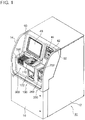
- FIG. 1 is a perspective view showing the external appearance of the money changer according to the present embodiment.
- FIG. 2 is a perspective view showing the internal structure of the money changer shown in FIG. 1 with a lower door provided at a front face of an outer housing being opened.
- FIG. 3 is a perspective view showing the internal structure of the money changer shown in FIG. 1 with an upper door provided at the front face of the outer housing being additionally opened from the state shown in FIG. 2 .
- FIG. 4 is a top view showing the structure of the lower door, as seen from above, in the money changer shown in FIG. 1 etc.
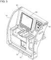
- FIG. 5 is a perspective view showing the structure of the upper door in the money changer shown in FIG.
- FIG. 6 is a vertical cross-sectional view of the upper door shown in FIG. 5 .
- FIG. 7 is a vertical cross-sectional view showing, in an enlarged manner, a small article placement part of the upper door shown in FIG. 6 .
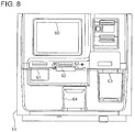
- FIG. 8 is a front view of the upper door shown in FIG. 5 .
- FIG. 9 is a vertical cross-sectional view of the upper door shown in FIG. 5 .
- FIG. 10 is a schematic block diagram schematically showing the structure of the money changer shown in FIG. 1 .
- the money changer 10 includes an outer housing 12 having a substantially rectangular parallelepiped shape. Inside the outer housing 12, a loose coin depositing and dispensing apparatus 100, a loose banknote depositing and dispensing apparatus 200, and a wrapped-coin dispensing apparatus 300 are arranged side by side in a horizontal direction.
- the loose coin depositing and dispensing apparatus 100, the loose banknote depositing and dispensing apparatus 200, and the wrapped-coin dispensing apparatus 300 each can be pulled out frontward in the horizontal direction to be taken out from the inside of the outer housing 12 independently from the other apparatuses.
- the upper door 14 and the lower door 16 are provided at the front face of the outer housing 12 of the money changer 10. As shown in FIG. 3 , the upper door 14 can be opened upward from the closed state shown in FIG. 1 , and the lower door 16 can be laterally opened from the closed state shown in FIG. 1 .
- each of the upper door 14 and the lower door 16 constitutes a part of the outer housing 12.
- light-emitting diodes (LED) 90 and 92 serving as state notifying units are provided, respectively.
- the light-emitting diodes 90 and 92 notify, to the outside by optical display, which of a plurality of previously set states the money changer 10 is in.
- the money changer 10 As shown in FIG. 10 , the money changer 10 according to the present embodiment is provided with a control unit 20 which is connected to each of the loose coin depositing and dispensing apparatus 100, the loose banknote depositing and dispensing apparatus 200, and the wrapped-coin dispensing apparatus 300 to control these apparatuses 100, 200, and 300. Further, as shown in FIG. 1 through FIG. 3 , an operation/display unit 40 composed of, for example, a touch panel or the like is provided on the back side of the upper door 14 of the money changer 10, and the operation/display unit 40 is connected to the control unit 20 (refer to FIG. 10 ).
- the operation/display unit 40 displays information about the handling condition of money, the inventory amount of money, and the like in each of the apparatuses 100, 200, and 300, and allows an operator to input various instructions to the control unit 20 through operations performed on the operation/display unit 40.
- the upper door 14 is provided with an opening 60 which allows the operator to operate the operation/display unit 40 and see the displayed content on the operation/display unit 40.
- the money changer 10 may be provided with a display unit composed of a monitor or the like, and an operation unit composed of a keyboard, operation keys, or the like, which units are provided separately from each other instead of the operation/display unit 40 composed of a touch panel or the like.
- the operation/display unit 40 is vertically moved in conjunction with an opening/closing operation of the upper door 14. That is, when the upper door 14 is opened upward from a front face upper portion of the outer housing 12 (refer to FIG. 3 ), the operation/display unit 40 is moved upward from the position thereof at which the upper door 14 is closed. Thus, when the loose coin depositing and dispensing apparatus 100 or the wrapped-coin dispensing apparatus 300 is pulled out frontward from the inside of the outer housing 12 after the upper door 14 is opened, the operation/display unit 40 is moved upward so that the loose coin depositing and dispensing apparatus 100 or the wrapped-coin dispensing apparatus 300 does not come into contact with the operation/display unit 40.
- the operation/display unit 40 is vertically moved in conjunction with the opening/closing operation of the upper door 14, the space inside the outer housing 12 can be utilized more effectively than in the case where the position of the operation/display unit 40 is fixed. Moreover, the operability of the operation/display unit 40 is improved. In addition, when the loose coin depositing and dispensing apparatus 100 or the wrapped-coin dispensing apparatus 300 is pulled out, the operation of pulling out the apparatus 100 or 300 can be reliably performed without being hindered by the operation/display unit 40.
- the operation/display unit 40 is not limited to the above structure that is vertically moved in conjunction with the opening/closing operation of the upper door 14.
- the operation/display unit 40 may have alternative structures as follows. That is, the operation/display unit 40 may be moved in the left-right direction or the front-rear direction in conjunction with the opening/closing operation of the upper door 14, or may be pivotally moved in conjunction with the opening/closing operation of the upper door 14.
- the upper door 14 is provided with: an opening 62 through which the operator inserts coins into a coin insertion mechanism 110 (described later) of the loose coin depositing and dispensing apparatus 100; an opening 64 through which the operator takes out coins from a coin outlet 172 (described later) of the loose coin depositing and dispensing apparatus 100; an opening 63 through which the operator inserts banknotes into a depositing unit 252 of the loose banknote depositing and dispensing apparatus 200 and takes out banknotes from a dispensing unit 260 of the loose banknote depositing and dispensing apparatus 200; and an opening 61 through which the operator takes out wrapped coin rolls from a wrapped-coin storage member 382 of a lift unit 380 in the wrapped-coin dispensing apparatus 300.
- a card reader 42 and a printer 44 are connected to the control unit 20 of the money changer 10.
- the card reader 42 reads an ID card or the like possessed by the operator to perform identification of the operator.
- the printer 44 functions as a printing unit which prints, on a receipt or the like, information about the handling condition of money, the inventory amount of money, and the like in each of the apparatuses 100, 200, and 300, or information about a money change process performed by the operator.
- a card insertion port through which a card is inserted into the card reader 42 and a receipt dispensing port through which a receipt is dispensed from the printer 44 are provided on the upper door 14 of the money changer 10.
- the card reader 42 adopted in the present embodiment does not take therein an ID card or the like inserted into the card insertion port, but returns the ID card or the like to the outside from the card insertion port after reading the card. Using this card reader 42 prevents the operator, who has inserted the ID card or the like into the card insertion port, from forgetting to take out the ID card or the like from the card insertion port.
- a projecting member 50 projecting inward from the inner face of the lower door 16 is provided on a lower portion of an inner face of the lower door 16.
- the structure of this projecting member 50 will be described with reference to FIG. 4 .
- the projecting member 50 has a slanted surface 50a inclined with respect to the inner face of the lower door 16.
- the projecting member 50 has the slanted surface 50a, even when the wrapped-coin dispensing apparatus 300 is pulled out frontward in the horizontal direction from the inside of the outer housing 12 in the state where the lower door 16 is not completely opened from a front face lower portion of the outer housing 12 of the money changer 10, a front end portion of the wrapped-coin dispensing apparatus 300 hits the slanted surface 50a of the projecting member 50, whereby the lower door 16 is opened in accordance with the operation of pulling out the wrapped-coin dispensing apparatus 300.
- the wrapped-coin dispensing apparatus 300 can be smoothly pulled out without being hindered by the lower door 16. Further, as shown in FIG. 2 and FIG.
- the projecting member 50 is provided with a projection-shaped buffer member 52 formed of rubber cushion or the like. Since the buffer member 52 is provided on the projecting member 50, even when the lower door 16 is closed in the state where a collection box 180 described later is not completely housed in a collection box housing 103 provided below the housing 102 of the loose coin depositing and dispensing apparatus 100, the projection-shaped buffer member 52, such as rubber cushion, provided on the projecting member 50 comes into contact with the collection box 180, whereby the collection box 180 can be pushed into the collection box housing 103. At this time, since the buffer member 52 is formed of rubber cushion or the like, the front face of the collection box 180 is prevented from being damaged.
- a small article placement part 70 on which small articles such as a wrapped coin roll taken out from the wrapped-coin dispensing apparatus 300 are placed is provided on the front face of the outer housing 12 (in particular , the upper door 14), and a raised portion 72 for preventing the small articles such as a wrapped coin roll placed on the small article placement part 70 from falling is provided at the front side of the small article placement part 70.
- the structure of the small article placement part 70 will be described in detail with reference to FIG. 5 through FIG. 7 .
- FIG. 5 is a perspective view showing the structure of the upper door 14 of the money changer 10 shown in FIG. 1
- FIG. 6 is a vertical cross-sectional view of the upper door 14 shown in FIG. 5
- FIG. 7 is a vertical cross-sectional view showing, in an enlarged manner, the small article placement part 70 of the upper door 14 shown in FIG. 6 .
- the small article placement part 70 is provided over the whole area in the width direction of the outer housing 12 (in particular, the upper door 14), and the small article placement part 70 has a small article placement surface 70a extending along a horizontal plane (refer to FIG. 6 and FIG. 7 ).
- the raised portion 72 is formed so as to be raised from the small article placement surface 70a at a position on the front side of the small article placement part 70. This raised portion 72 is also provided over the whole area in the width direction of the outer housing 12. (in particular, the upper door 14).
- the operator can temporarily place a small article, such as a wrapped coin roll taken out from the wrapped-coin dispensing apparatus 300, on the small article placement part 70, in order to assist the operator. Further, since the small article placement part 70 has the raised portion 72, the small article placed on the small article placement surface 70a of the small article placement part 70 is prevented from falling.
- a small article such as a wrapped coin roll taken out from the wrapped-coin dispensing apparatus 300
- slanted surfaces 80 and 82 are provided which are inclined with respect to the horizontal plane so as to be gradually increased in height with distance from the opening 62. Specifically, as shown in FIG. 8 and FIG. 9 , on the upper door 14, at positions on the both sides of the opening 62 through which the operator inserts coins into the coin insertion mechanism 110 (described later) of the loose coin depositing and dispensing apparatus 100, slanted surfaces 80 and 82 are provided which are inclined with respect to the horizontal plane so as to be gradually increased in height with distance from the opening 62. Specifically, as shown in FIG. 8 and FIG.
- the slanted surface 80 provided to the left of the opening 62 is inclined with respect to the horizontal plane so as to be gradually increased in height with distance from the opening 62 in the leftward direction
- the slanted surface 82 provided to the right of the opening 62 is inclined with respect to the horizontal plane so as to be gradually increased in height with distance from the opening 62 in the rightward direction.
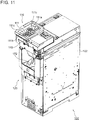
- FIG. 11 is a perspective view showing the external appearance of the loose coin depositing and dispensing apparatus 100.
- FIG. 12 is a side view showing the internal structure of the loose coin depositing and dispensing apparatus 100 shown in FIG. 11 .
- FIG. 13 is a front view showing the internal structure of the loose coin depositing and dispensing apparatus 100 shown in FIG. 11 .
- FIGS. 14 to 21 illustrate the structure of the coin insertion mechanism 110 provided in the loose coin depositing and dispensing apparatus 100 shown in FIG. 11 .
- FIGS. 22 to 28 illustrate the structure of the collection box 180 housed in the collection box housing 103 provided adjacent to an external lower portion of the housing 102 of the loose coin depositing and dispensing apparatus 100 shown in FIG. 11 .
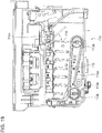
- the loose coin depositing and dispensing apparatus 100 is provided with: the housing 102 having a substantially rectangular parallelepiped shape; the coin insertion mechanism 110 for inserting coins from the outside to the inside of the housing 102; and an escrowing/feeding mechanism 130 to which coins inserted into the housing 102 by the loose coin depositing and dispensing apparatus 100 are transported and escrowed, and which feeds the escrowed coins one by one.
- the structure of the coin insertion mechanism 110 will be described later in detail.
- the escrowing/feeding mechanism 130 includes: a rotary disk 132 which is inclined at a predetermined angle with respect to the vertical direction and is rotated in the inclined position; and a cover member 134 which forms a coin escrow space 133 for escrowing coins therein, between a surface 132b of the rotary disk 132 and the cover member 134.
- a depositing transport unit 120 which transports, one by one, the coins fed from the escrowing/feeding mechanism 130, and the depositing transport unit 120 is provided with a recognition unit 122 which recognizes the denomination, authenticity, fitness, version (old/new), and the like of the coins transported by the depositing transport unit 120.
- the depositing transport unit 120 is provided with an endless belt 120p.
- the endless belt 120p is stretched over a plurality of pulleys.
- the endless belt 120p is circularly moved in a counter clockwise direction in FIG. 12 by a motor mounted to one pulley.
- a plurality of projecting members are provided on the endless belt 120p at equal intervals, and one coin is hooked by one projecting member, so that the coins are transported on a transport surface one by one.
- a plurality of (for example six, as shown in figure 12 ) storing/feeding mechanisms 150 are provided below the depositing transport unit 120.
- Coins are transported from the depositing transport unit 120 to the storing/feeding mechanisms 150 through chutes 126 by sorting units 124 provided in the depositing transport unit 120 , on the basis of the recognition result of the coins processed by the recognition unit 122.
- the transported coins are then stored in the storing/feeding mechanism 150.
- the depositing transport unit 120 is provided with a reject sorting unit 127 which is a sorting unit for reject coins.
- a coin which is recognized to be a counterfeit coin by the recognition unit 122 is transported to a coin outlet 172 described later through a chute (not shown) for reject coins by the reject sorting unit 127.
- a reject unit (not shown) for rejecting the reject coins to the outside of the apparatus may be provided in the vicinity of the coin outlet 172.
- a coin recognized to be a counterfeit coin by the recognition unit 122 is transported by the reject sorting unit 127, as a reject coin, to the reject unit through the chute for reject coins.
- each storing/feeding mechanism 150 feeds out, one by one, the coins stored in the storing/feeding mechanism 150. More specifically, each storing/feeding mechanism 150 includes: a rotary disk 152 which is inclined at a predetermined angle with respect to the vertical direction and is rotated in the inclined position; and a cover member 154 which forms a coin storage space 153 for storing coins therein, between a surface 152b of the rotary disk 152 and the cover member 154.
- the loose coin depositing and dispensing apparatus 100 is provided with the coin outlet 172 through which coins are dispensed to the outside of the housing 102.
- a dispensing transport unit 170 for transporting the coins fed out from each storing/feeding mechanism 150 to the coin outlet 172 is provided in the housing 102.
- the dispensing transport unit 170 includes: a first dispensing transport section 170a which is provided below the storing/feeding mechanisms 150 and extends substantially in the horizontal direction; and a second dispensing transport section 170b which transports the coins transported from the first dispensing transport section 170a to the coin outlet 172.
- the dispensing transport unit 170 is composed of an endless belt 170p stretched over a plurality of pulleys.
- the endless belt 170p is circularly moved by a motor mounted to one pulley in both a clockwise direction and a counter clockwise direction in FIG. 12 . Further, a plurality of projecting members (not shown) are provided on the endless belt 170p at equal intervals, and one or more coins are hooked by one projecting member, so that the coins are transported one or more at a time by the endless belt 170p.
- the collection box 180 used as an overflow coin storage unit is provided below the dispensing transport unit 170.
- the collection box 180 can be pulled out frontward in the horizontal direction from the collection box housing 103 provided below the housing 102.
- the endless belt 170p is circularly moved in the clockwise direction in FIG. 12 , coins are transported from the first dispensing transport section 170a of the dispensing transport unit 170 to the collection box 180.
- the collection box 180 is pulled out frontward from the collection box housing 103, whereby the coins can be collected together with the collection box 180.
- the structure of the collection box 180 will be described later in detail.
- the loose coin depositing and dispensing apparatus 100 is provided with an overflow chute 125 for directly transporting coins from the depositing transport unit 120 to the dispensing transport unit 170 without transporting the coins through the storing/feeding mechanisms 150.
- the depositing transport unit 120 is provided with an overflow sorting unit 123 for sorting coins to be transported to the overflow chute 125, separately from the sorting unit 124 for sorting coins to be transported to the chute 126 corresponding to each storing/feeding mechanism 150.
- a lower end portion of the overflow chute 125 is located above the endless belt 170p of the dispensing transport unit 170. In this structure, the coins sorted by the overflow sorting unit 123 among the coins transported by the depositing transport unit 120 are transported onto the endless belt 170p of the dispensing transport unit 170 through the overflow chute 125.
- the overflow chute 125 is provided, when the storing/feeding mechanism 150 corresponding to the denomination of a coin recognized by the recognition unit 122 is full of coins, the coin of the denomination for which the storing/feeding mechanism 150 is full of coins is sorted by the overflow sorting unit 123 to be transported onto the endless belt 170p of the dispensing transport unit 170 by the overflow chute 125, without suspending transport of coins by the depositing transport unit 120. Then, the coin transported onto the endless belt 170p of the dispensing transport unit 170 by the overflow chute 125 is transported to the collection box 180 by the endless belt 170p.
- FIG. 14 is a perspective view showing the structure of the coin insertion mechanism 110.
- FIG. 15 is a top view showing the structure of the coin insertion mechanism 110 shown in FIG. 14 .
- FIG. 16 and FIG. 17 is a vertical cross-sectional view of the coin insertion mechanism 110 shown in FIG. 15 , taken along the direction of arrows A-A in FIG. 15 .
- FIG. 18 is a vertical cross-sectional view of the coin insertion mechanism 110 shown in FIG. 15 , taken along the direction of arrows B-B in FIG. 15 .
- FIG. 16 and FIG. 17 is a vertical cross-sectional view of the coin insertion mechanism 110 shown in FIG. 15 , taken along the direction of arrows B-B in FIG. 15 .
- FIG. 19 is a vertical cross-sectional view of the coin insertion mechanism 110 shown in FIG. 15 , taken along the direction of arrows C-C in FIG. 15 .
- FIG. 20 is a perspective view showing the state where a coin receiving unit 140 is opened upward in the coin insertion mechanism 110 shown in FIG. 15 .
- FIG. 21 is a perspective view showing the structure of a foreign material receiving unit 112 provided in the coin insertion mechanism 110 shown in FIG. 15 .
- the coin insertion mechanism 110 for inserting coins from the outside to the inside of the housing 102 of the loose coin depositing and dispensing apparatus 100 includes: a coin receiving section 111 which receives coins inserted into a coin inlet provided at an upper face of the housing 102, and removes a foreign material such as a clip mixed with the received coins; and a coin feeding unit 115 which feeds the coins transported from the coin receiving section 111 to the inside of the housing 102 of the loose coin depositing and dispensing apparatus 100, and transports the coins to the escrowing/feeding mechanism 130.
- a chute 113 which forms a coin transport path for transporting the coins received by the coin receiving section 111 to the coin feeding unit 115 is provided between the coin receiving section 111 and the coin feeding unit 115.
- the coin receiving section 111 and the chute 113 are provided in the coin receiving unit 140 which can be opened upward from the upper portion of the housing 102 of the loose coin depositing and dispensing apparatus 100, and the operator can access the coin feeding unit 115 by opening the coin receiving unit 140 upward. Therefore, when, for example, failure in feeding coins occurs in the coin feeding unit 115, the operator can remove coins jammed in the coin feeding unit 115 by opening the coin receiving unit 140 upward as shown in FIG. 20 .
- the coin receiving section 111 is composed of a tray including a first tray portion 111a and a second tray portion 111b, and the coins inserted into the coin inlet are received by this tray.
- the second tray portion 111b is provided adjacent to the chute 113.
- the first tray portion 111a is inclined with respect to the horizontal plane so that an upper face thereof extends obliquely downward toward the second tray portion 111b, and the first tray portion 111a is not adjacent to the chute 113. Therefore, the coins received by the first tray portion 111a are first transported to the second tray portion 111b and then transported from the second tray portion 111b to the chute 113.
- the first tray portion 111a and the second tray portion 111b in the coin receiving section 111 are integrally turnable about a shaft 111d extending in the horizontal direction. More specifically, the first tray portion 111a and the second tray portion 111 b are integrally turnable between a coin receiving position at which the coins inserted into the coin inlet are received as shown in FIG. 16 and a coin transport position at which the coins received by the first tray portion 111 a and the second tray portion 111b are transported to the chute 113 as shown in FIG. 17 .
- the first tray portion 111 a and the second tray portion 111 b are at the coin receiving position shown in FIG. 16 by their own weights.
- the operator manually lifts the first tray portion 111a and the second tray portion 111b integrally so that the first tray portion 111 a and the second tray portion 111 b are turned about the shaft 111 d to be moved to the coin transport position shown in FIG. 17 , the coins received by the first tray portion 111a and the second tray portion 111b are transported to the chute 113 by their own weights.
- the coin insertion mechanism 110 is not limited to the above structure in which the first tray portion 111 a and the second tray portion 111 b are manually turned about the shaft 111d.
- the coin insertion mechanism 110 may be provided with a drive motor (not shown) for turning the first tray portion 111a and the second tray portion 111b about the shaft 111d.
- the operator may manually transport the coins received by the first tray portion 111 a and the second tray portion 111 b to the chute 113.
- a step is formed between the first tray portion 111 a and the second tray portion 111 b so that an edge portion, on the second tray portion 111b side, of the first tray portion 111a is slightly higher in height than an edge portion, on the first tray portion 111 a side, of the second tray portion 111 b.
- the upper face of the second tray portion 111 b is inclined with respect to the horizontal plane so that the height thereof is gradually reduced with distance from the shaft 111d, when the second tray portion 111b is in the coin receiving position.
- each of the first tray portion 111a and the second tray portion 111b is provided with a plurality of holes 111c for eliminating foreign materials.
- the size of each hole 111 c is smaller than the size of coins to be handed by the loose coin depositing and dispensing apparatus 100.
- the foreign material receiving unit 112 for receiving foreign materials that have passed through the holes 111c is provided below the first tray portion 111a and the second tray portion 111b.
- the foreign material receiving unit 112 is detachable from the coin insertion mechanism 110.
- the structure of the foreign material receiving unit 112 is shown in FIG. 21 in detail.
- the foreign material receiving unit 112 is formed of, for example, plastic or the like.
- a projection 112a for mounting the foreign material receiving unit 112 to the coin insertion mechanism 110 is provided on one of side faces of the foreign material receiving unit 112.
- a projection for mounting the foreign material receiving unit 112 to the coin insertion mechanism 110 is also provided on a side face, of the foreign material receiving unit 112, opposite to the side face on which the projection 112a is provided.
- the position of the foreign material receiving unit 112 is not changed even when the coin receiving unit 140 is opened upward as shown in FIG. 20 .
- the foreign material receiving unit 112 can be detached from the coin insertion mechanism 110 in the state where the coin receiving unit 140 is opened upward.
- the projection 112a is detached from the coin insertion mechanism 110 by pressing the side face, of the foreign material receiving unit 112, on which the projection 112a is provided.
- the side face, of the foreign material receiving unit 112, on which the projection 112a is provided is lifted upward and slightly turned, and the foreign material receiving unit 112 is slightly displaced rightward, whereby the projection (not shown) provided on the side face, of the foreign material receiving unit 112, opposite to the side face on which the projection 112a is provided is detached from the coin insertion mechanism 110. Thereafter, the foreign material receiving unit 112 is lifted further upward to detach the foreign material receiving unit 112 from the coin insertion mechanism 110.
- the chute 113 includes a first guide portion 113a forming a bottom face of the coin transport path, and a second guide portion 113b forming an upper face of the coin transport path.
- the coins transported from the coin receiving section 111 to the chute 113 are conveyed so as to pass through an area between the first guide portion 113a and the second guide portion 113b to be transported to the coin feeding unit 115.
- the first guide portion 113a forming the bottom face of the coin transport path is inclined with respect to the horizontal plane so as to extend obliquely downward toward the coin feeding unit 115 from the coin receiving section 111.
- a wrapped-coin transport regulating unit 113c is provided so as to be spaced apart from the first guide portion 113a.
- the distance between the first guide portion 113a and the wrapped-coin transport regulating unit 113c is smaller than the diameter of coins to be handled by the loose coin depositing and dispensing apparatus 100, and the coins transported from the coin receiving section 111 to the chute 113 move toward the second guide portion 113b while sliding on the first guide portion 113a by their own weights, not in a standing state but in a laterally lying state.
- the wrapped-coin transport regulating unit 113c Since the wrapped-coin transport regulating unit 113c is provided, even when the operator mistakenly inserts a wrapped coin roll into the coin inlet of the loose coin depositing and dispensing apparatus 100, the wrapped coin roll does not pass through the space between the first guide portion 113a and the wrapped-coin transport regulating unit 113c but is caught by the wrapped-coin transport regulating unit 113c, thereby preventing the wrapped coin roll from being transported to the coin feeding unit 115 described later. When the wrapped coin roll is caught by the wrapped-coin transport regulating unit 113c, the operator can take out the wrapped coin roll by putting his/her hand into the coin inlet.
- a shutter 114 for selectively blocking transport of coins from the coin receiving section 111 to the coin feeding unit 115 is openably and closably provided on the chute 113.
- This shutter 114 is movable between a closed position at which the shutter 114 is located between the first guide portion 113a and the second guide portion 113b of the chute 113 and closes the coin transport path as shown in FIG. 16 , and an opened position at which the shutter 114 is retracted from the coin transport path to be located above the second guide portion 113b as shown in FIG. 17 .
- the shutter 114 is in the closing position shown in FIG.
- the coins transported from the coin receiving section 111 to the chute 113 are blocked by the shutter 114 and are not transported to the coin feeding unit 115.
- a coin passage detecting sensor (not shown) for detecting passage of coins is provided.
- the coin feeding unit 115 includes a transport belt 115a stretched over a plurality of pulleys 115b, and the coins transported from the chute 113 to the coin feeding unit 115 are received on the transport belt 115a.
- a drive motor (not shown) is connected to one of the plurality of pulleys 115b, and the pulley 115b connected to the drive motor is driven to rotate by the drive motor, whereby the transport belt 115a can be circularly moved in both the clockwise direction and the counter clockwise direction in FIG. 19 .
- the transport belt 115a is circularly moved in the clockwise direction in FIG. 19
- the coins transported from the chute 113 to the coin feeding unit 115 are transported rightward in FIG. 19 on the transport belt 115a, and drop off from an end portion of the transport belt 115a as indicated by an arrow in FIG. 19 to be transported to the escrowing/feeding mechanism 130.
- a coin transport amount restricting member 116 for restricting the amount of coins to be transported from the coin feeding unit 115 to the escrowing/feeding mechanism 130 is provided above an end portion, of the transport belt 115a, on the escrowing/feeding mechanism 130 side (i.e., on the right side in FIG. 19 ).
- the coin transport amount restricting member 116 is formed of a plate-shaped elastic body (specifically, a material having flexibility) such as urethane rubber, and a lower end portion of the coin transport amount restricting member 116 is slightly separated upward from an upper face of the transport belt 115a.
- the coin transport amount restricting member 116 is provided above the transport belt 115a, it is possible to avoid a situation that a large number of coins present on the transport belt 115a drop off from the end portion of the transport belt 115a at one time like an avalanche and are transported to the escrowing/feeding mechanism 130. Further, the coin transport amount restricting member 116 is swingable about a shaft 116a, between a position indicated by a solid line in FIG. 19 and a position indicated by a two-dot chain line in FIG. 19 .
- the caught coins can be separated from the coin transport amount restricting member 116 to be received on the transport belt 115a or can be dropped off toward the escrowing/feeding mechanism 130 side, by causing the coin transport amount restricting member 116 to swing.
- the operation of the coin insertion mechanism 110 having the above structure will be described.
- the shutter 114 provided on the chute 113 is opened.
- the transport belt 115a of the coin feeding unit 115 is circularly moved in the clockwise direction in FIG. 19 .
- the operator inserts coins into the coin inlet provided at the upper face of the housing 102, the coins are received by the first tray portion 111 a and/or the second tray portion 111b of the coin receiving section 111. At this time, foreign materials mixed with the coins are transported to the foreign material receiving unit 112 through the holes 111c for eliminating foreign materials.
- the coin received by the first tray portion 111a and/or the second tray portion 111 b are transported to the chute 113 by their own weights and then transported from the chute 113 to the coin feeding unit 115.
- the coins transported to the coin feeding unit 115 are received on the transport belt 115a.
- the transport belt 115a is circularly moved in the clockwise direction in FIG. 19 , whereby the coins on the transport belt 115a drop off from the end portion of the transport belt 115a as indicated by an arrow in FIG. 19 to be transported to the escrowing/feeding mechanism 130.
- the coin passage detecting sensor (not shown) provided in the chute 113 no longer detects passage of coins
- the shutter 114 is closed to block transport of coins from the coin receiving section 111 to the coin feeding unit 115.
- the transport belt 115a is circularly moved for a predetermined period of time in a direction opposite to the direction of transporting the coins to the escrowing/feeding mechanism 130 (i.e., counter clockwise direction in FIG.
- the coin transport amount restricting member 116 swings so that the coins in contact with the coin transport amount restricting member 116 are separated from the coin transport amount restricting member 116.
- the coins caught between the side wall of the coin feeding unit 115 and the coin transport amount restricting member 116 can be separated from the coin transport amount restricting member 116 and received on the transport belt 115a.
- the transport belt 115a is circularly moved for a predetermined period of time in the direction opposite to the coin transporting direction toward the escrowing/feeding mechanism 130, and thereafter is again circularly moved in the coin transporting direction toward the escrowing/feeding mechanism 130 (clockwise direction in FIG. 19 ).
- the coins separated from the coin transport amount restricting member 116 and received on the transport belt 115a are transported to the escrowing/feeding mechanism 130.
- FIG. 22 is a perspective view showing the structure of the collection box 180.
- FIG. 23 is a side view showing the state where a cord 183 is hooked on the collection box 180 shown in FIG 22 , and the cord 183 is pulled to convey the collection box 180.
- FIG. 24 is a perspective view showing the structure, on a bottom face side, of the collection box 180 shown in FIG. 22 .
- FIG. 25 is a vertical cross-sectional view showing the structure of a rear wheel 187 provided on the collection box 180 shown in FIG. 24 .
- FIG. 26 is a side view schematically showing the state where the collection box 180 shown in FIG.
- FIG. 22 is housed inside the collection box housing 103 disposed below the housing 102 of the loose coin depositing and dispensing apparatus 100.
- FIG. 27 is a side view schematically showing the state where the collection box 180 shown in FIG. 22 is in the middle of being pulled out from the inside of the collection box housing 103.
- FIG. 28 is a top view showing the internal structure of the collection box 180 shown in FIG. 22 as seen from above, with an upper lid 181 being opened.
- the collection box 180 has a substantially rectangular parallelepiped shape. At the bottom of the collection box 180, a pair of left and right front wheels 186 and a pair of left and right rear wheels 187 are provided at the front and the rear, respectively.
- the collection box 180 is provided with the upper lid 181.
- the operator can take out the coins stored in the collection box 180 by opening the upper lid 181.
- the upper lid 181 is provided with an opening 181a through which the coins transported from the endless belt 170p of the dispensing transport unit 170 pass, and the opening 181 a is provided with a shutter for closing the opening 181a.
- the opening 181 a is closed by the shutter.
- the shutter automatically opens the opening 181 a.
- the collection box housing 103 for housing the collection box 180 is provided below the housing 102 of the loose coin depositing and dispensing apparatus 100 (refer to FIG. 26 and FIG. 27 ).
- This collection box housing 103 is attached to a lower face of the housing 102 of the loose coin depositing and dispensing apparatus 100. Regardless of whether the collection box 180 is housed in the collection box housing 103 or is pulled out from the collection box housing 103, the collection box housing 103 can be pulled out frontward, integrally with the housing 102 of the loose coin depositing and dispensing apparatus 100, from the inside of the outer housing 12 of the money changer 10.
- the collection box 180 when the cord 183 is hooked on a front-side end portion of the collection box 180 and pulled, the collection box 180 can be pulled out from the collection box housing 103 and/or the collection box 180 pulled out from the collection box housing 103 can be conveyed.
- the collection box 180 is provided with a cord housing 182 for housing the cord 183.
- the cord housing 182 is provided at a position on the front side in the depth direction of the housing 102 when the collection box 180 is housed in the collection box housing 103.
- the cord housing 182 is provided with through-holes 184 on which the cord 183 taken out from the cord housing 182 is hooked.
- the through-holes 184 are formed at both side faces of the cord housing 182 when the collection box housing 103 is viewed from the front.
- the operator pulls out the collection box 180 from the collection box housing 103 and/or conveys the collection box 180 pulled out from the collection box housing 103, by hooking the cord 183 on the front-side end portion of the collection box 180 and pulling the cord 183. Therefore, when the operator pulls out, from the collection box housing 103, or conveys the heavy collection box 180 in which a large number of coins are stored, the burden on the operator can be reduced as compared to the case where the operator conveys the collection box 180 with his/her hands holding the collection box 180.
- the front wheels 186 and the rear wheels 187 have different heights. Specifically, as shown in FIG. 24 and FIG. 25 , there is an opening in the vicinity of each rear wheel 187 at the bottom face of the collection box 180, and a half of the rear wheel 187 is in the opening so as to be lower in height than the front wheel 186. More specifically, each rear wheel 187 is supported by a wheel support member 187b so as to rotate about a shaft 187a, and the wheel support member 187b is mounted on a metal plate 187c provided inside the collection box 180. Thus, the rear wheel 187 is half inserted in the opening formed at the bottom face of the collection box 180, and therefore is lower in height than the front wheel 186.
- the bottom face of the collection box housing 103 is substantially flush with a floor surface on which the money changer 10 is installed.
- the operator can smoothly perform the action of pulling out the collection box 180 from the collection box housing 103 and the action of housing the collection box 180 in the collection box housing 103.
- the collection box housing 103 is provided below the housing 102 of the loose coin depositing and dispensing apparatus 100, even when the lower door 16 of the money changer 10 is opened but the upper door 14 thereof is not opened as shown in FIG. 2 , the collection box 180 can be pulled out from the collection box housing 103.
- the operator can pull out the collection box 180 from the collection box housing 103 without opening the upper door 14, whereby the work burden on the operator can be reduced.
- the height of the bottom face of the collection box housing 103 varies depending on the position in the depth direction (rightward direction in FIG. 26 and FIG. 27 ) of the housing 102. Specifically, the height of the collection box housing 103 is set so that the internal bottom face of the collection box 180 is in the horizontal state when the collection box 180 is housed in the collection box housing 103. More specifically, the collection box housing 103 includes: a pedestal portion 104 on which the rear wheels 187 of the collection box 180 ride when the collection box 180 is housed in the collection box housing 103; and an inclined portion 105 which has a slanted surface inclined with respect to the horizontal plane, and connects the bottom face of the housing 102 to the pedestal portion 104.
- the rear wheels 187 of the collection box 180 ride on the pedestal portion 104 when the collection box 180 is housed in the collection box housing 103, the internal bottom face of the collection box 180 is in the horizontal state although the height of the front wheels 186 is different from the height of the rear wheels 187 as shown in FIG. 26 .
- the rear wheels 187 of the collection box 180 run on the pedestal portion 104 and come into contact with the floor surface through the inclined portion 105.
- the height of the collection box housing 103 is set so that the internal bottom face of the collection box 180 is in the horizontal state when the collection box 180 is housed in the collection box housing 103, the coins transported from the endless belt 170p of the dispensing transport unit 170 to the collection box 180 can be uniformly stacked over the entirety of the internal area of the collection box 180.
- a sheet 188 formed of an elastic material such as rubber is spread on an inner bottom face 180a of the collection box 180.
- the sheet 188 provided on the inner bottom face 180a of the collection box 180 can reduce impact sound that is generated when the coins drop from the endless belt 170p of the dispensing transport unit 170 and hit the inner bottom face of the collection box 180, thereby providing noise prevention.
- FIG. 29 is a perspective view showing an external appearance of the loose banknote depositing and dispensing apparatus 200.
- FIG. 30 is a side view showing the internal structure of the loose banknote depositing and dispensing apparatus 200 shown in FIG. 29 .
- the loose banknote depositing and dispensing apparatus 200 includes a housing 202 having a substantially rectangular parallelepiped shape, and a depositing unit 252 and a dispensing unit 260 are provided at a front face (right side face in FIG. 30 ) of the housing 202.
- the depositing unit 252 is provided with a depositing unit cover 252a and a banknote feeding mechanism 252b.
- the banknotes are set in the depositing unit 252 in a stacked state, and then the banknotes are fed by the banknote feeding mechanism 252b into the housing 202 one by one.
- a transport unit 264 is provided in the housing 202 of the loose banknote depositing and dispensing apparatus 200, and the transport unit 264 transports, one by one, the banknotes fed into the housing 202 by the banknote feeding mechanism 252b.
- the transport unit 264 is provided with a recognition unit 266, and the recognition unit 266 recognizes the denomination, authenticity, fitness, version (old/new), and the like of each of the banknotes fed into the housing 202 by the banknote feeding mechanism 252b.
- a plurality of storing/feeding units 270 are provided in the housing 202, and each storing/feeding unit 270 is connected to the transport unit 264.
- the respective storing/feeding units 270 store banknotes by denominations. More specifically, the banknotes fed into the housing 202 by the banknote feeding mechanism 252b are transported by denominations by the transport unit 264 to the storing/feeding units 270 on the basis of the recognition result by the recognition unit 266.
- Each storing/feeding unit 270 is able to feed, one by one, the banknotes stored therein to the transport unit 264.
- Each storing/feeding unit 270 may be a tape-reel type storing/feeding unit which reels up a pair of tapes, between which banknotes are sandwiched one by one, together with the banknotes as shown in FIG. 30 , or may be a stacker type storing/feeding unit (not shown) which stores banknotes in a stacked manner.
- a cassette attaching unit 280 to which a cash transport cassette 235 is detachably attached is provided in the housing 202.
- the cassette attaching unit 280 is connected to the transport unit 264.
- banknotes can be transported from the transport unit 264 to the cash transport cassette 235, and banknotes stored in the cash transport cassette 235 can be fed to the transport unit 264.
- the banknotes can be collected together with the cash transport cassette 235.
- a tape-reel type storing/feeding unit which reels up a pair of tapes, between which banknotes are sandwiched one by one, together with the banknotes, is provided in the cash transport cassette 235.
- the structure of the cash transport cassette 235 is not limited thereto.
- a stacker type storing/feeding unit which stores banknotes in a stacked manner may be provided in the cash transport cassette 235.
- the dispensing unit 260 is provided with a dispensing unit shutter 260a. After banknotes are transported to the dispensing unit 260, the operator can take out the banknotes stacked in the dispensing unit 260 by opening the dispensing unit shutter 260a. Alternatively, the shutter 260a may be automatically opened after dispensing is completed.
- a door 236 is provided on the front face of the housing 202 at a position opposed to the cash transport cassette 235.
- the storing/feeding units 270 are housed in a drawer unit 272, and the drawer unit 272 can be pulled out frontward from the housing 202.
- an elastic body 237 such as sponge or rubber, having a substantially rectangular parallelepiped shape is adhered to a front face of the door 236. Since the elastic body 237 is adhered to the front face of the door 236, when the upper door 14 of the money changer 10 is closed from the state shown in FIG. 3 , the upper door 14 comes into contact with the elastic body 237, thereby preventing the door 236 from being damaged by the upper door 14.
- FIG. 31 through FIG. 60 wrapped coin rolls are represented by reference character W.
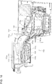
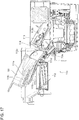
- the wrapped-coin dispensing apparatus 300 includes: the housing 302 having a substantially rectangular parallelepiped shape; a plurality of (e.g., six) storage units 310 arranged along the vertical direction in the housing 302; and the lift unit 380 movable in the vertical direction.
- Each storage unit 310 is provided with a dispensing mechanism 319 which dispenses, one by one, wrapped coin rolls stored in the storage unit from a side closest to a portion, at a lowest height level, of a bottom face 312.
- the lift unit 380 includes: the wrapped-coin storage member 382 in which wrapped coin rolls dispensed by the dispensing mechanism 319 of each storage unit 310 are stored; and a dispensed wrapped-coin detection unit 384 which detects the wrapped coin rolls dispensed by the dispensing mechanism 319 of each storage unit 310.
- a shutter 390 is provided which opens and closes a wrapped-coin outlet through which the wrapped coin rolls stored in the wrapped-coin storage member 382 of the lift unit 380 are taken out when the wrapped-coin storage member 382 is at an upper position (solid-line position in FIG. 32 ).
- a control unit 370 which controls the lift unit 380, and the dispensing mechanisms 319 provided in the respective storage units 310.
- the components of the wrapped-coin dispensing apparatus 300 will be described in detail.
- each storage unit 310 stores, therein, a plurality of wrapped coin rolls on the bottom face (storage face) 312 inclined with respect to the horizontal plane so that the wrapped coin rolls are stacked in a direction (i.e., a lower left direction in FIG. 32 , FIG. 37 , etc.) in which the wrapped coin rolls run along the inclined bottom face 312.
- a plurality of wrapped coin rolls are stored so as to be stacked may include: a case where the wrapped coin rolls are stored so as to be stacked in multiple layers on the bottom face 312; a case where the wrapped coin rolls are stored side by side in a single layer (single line) on the bottom face 312; and a case where one wrapped coin roll is stored, depending on the number of the wrapped coin rolls stored in the storage unit 310.
- the above expression may also include: a case where the wrapped coin rolls are stored in a regularly arranged manner; and a case where the wrapped coin rolls are stored in the same direction but not in a regularly arranged manner. That is, the above expression means that it is possible to store the wrapped coin rolls so as to be stacked in multiple layers.
- the wrapped coin rolls are not necessarily stored so as to be stacked in multiple layers, and the wrapped coin rolls are not necessarily stored in a regularly arranged manner.
- the inclination angle of the bottom face 312 of each storage unit 310 with respect to the horizontal plane is within a range of 8 to 20°, and the maximum static friction coefficient of the bottom face 312 of each storage unit 310 with respect to the wrapped coin rolls is within a range of 0.01 to 0.15.
- each wrapped coin roll present on the bottom face 312 slides or runs by its own weight along the inclined bottom face 312 without being stopped by a friction acting between the wrapped coin roll and the bottom face 312, and is shifted to the dispensing mechanism 319 side.
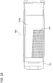
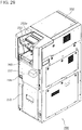
- Each storage unit 310 has a pair of side walls that form a storage area for wrapped coin rolls therebetween. As shown in FIG. 31 , at least one of the pair of side walls is configured as an openable/closable door 314 through which wrapped coin rolls are put in and taken out from the storage unit 310.
- the side wall of the storage unit 310 configured as the door 314, is formed of a transparent member or a semi-transparent member, for example, so that the operator can visually observe the inside of the storage unit 310 through the door 314.
- the door 314 may have a slit, hole, or the like through which the operator can visually observe the inside of the storage unit 310. As shown in FIG.
- two hinges 316 are provided at a lower edge portion of the door 314, and the door 314 is openably and closably attached to a side face of the housing 302 of the wrapped-coin dispensing apparatus 300 by means of the hinges 316.
- the operator can put the wrapped coin rolls from the lateral side of the storage unit 310 by opening the door 314.
- a stopper member 314a is provided which regulates the open angle of the door 314 to a predetermined angle so that, when the door 314 is opened, a gap of a predetermined size is formed between the opened door 314 and the side face of the wrapped-coin dispensing apparatus 300.
- the stopper member 314a of the opened door 314 comes into contact with the stopper member 314a of a door 314 provided immediately beneath the opened door 314, whereby the open angle of the door 314 is regulated to the predetermined angle.
- a stopper member 313 is also provided below a door 314 located at the lowermost position among the six doors 314.
- the stopper member 314a of this door 314 comes into contact with the stopper member 313, whereby the open angle of the door 314 located at the lowermost position is set at the predetermined angle. Since the stopper member 314a is provided on each door 314 and the stopper member 313 is provided, an operator's finger(s) is/are prevented from being caught between each door 314 and the side face of the wrapped-coin dispensing apparatus 300 when the operator opens the door 314. When vertically adjacent doors 314 are opened, the stopper members 313 of these doors 314 do not come into contact with each other.
- the hinges 316 provided on each door 314 also act as a stopper member for regulating the open angle of the door 314 to a predetermined angle, similarly to the stopper member 314a provided on each door 314, and the stopper member 313.
- each storage unit 310 is provided with the dispensing mechanism 319 which dispenses, one by one, the wrapped coin rolls stored in the storage unit 310 from the side closest to the portion, at the lowest height level, of the bottom face 312.
- the dispensing mechanism 319 includes a rotor 320 which rotates in the counter clockwise direction in FIG. 32 about a rotation shaft 322 as an axial center extending in a direction orthogonal to the inclination direction of the storage unit 310 and in the horizontal direction (i.e., extending in a direction orthogonal to the surface of the sheet of FIG. 32 ).
- Each rotor 320 is provided with at least two (three in the example shown in FIG. 32 through FIG. 36 , etc.) recessed portions 324 each receiving, one by one, the wrapped coin rolls stored in the storage unit 310.
- the dispensing mechanism 319 includes: a drive unit 321 (refer to FIG. 33 ) which causes the rotor 320 to rotate about the rotation shaft 322; a rotation position detecting unit 350 which detects a rotation position of the rotor 320; and a gate unit 330 which is provided above the rotor 320, and avoids a situation that a wrapped coin roll stored in the storage unit 310 does not enter the recessed portion 324 of the rotor 320 but passes above the rotor 320 and is dispensed.
- the drive unit 321 can cause the rotor 320 to rotate in both a forward direction (i.e., the counter clockwise direction in FIG. 32 ) in which wrapped coin rolls are dispensed from the storage unit 310 by the rotor 320 and a reverse direction (i.e., the clockwise direction in FIG. 32 ) opposite to the forward direction.
- the drive unit 321 can change the rotation speed of the rotor 320.
- three recessed portions 324 are provided in the rotor 320 at equal intervals in the rotation direction of the rotor 320 about the rotation shaft 322.
- the rotor 320 is in the rotation position as shown in FIG. 35 , one wrapped coin roll located on a portion, at the lowest height level, of the bottom face 312, among a plurality of wrapped coin rolls stored in the storage unit 310, is received by the recessed portion 324.
- Each recessed portion 324 may be provided with a received wrapped-coin detecting unit 329 which detects whether or not a wrapped coin roll is received in the recessed portion 324.
- the received wrapped-coin detecting unit 329 is composed of an optical sensor or the like having a photoemitter and a photodetector, for example.
- an optical axis between the photoemitter and the photodetector is cut off by the wrapped coin roll, whereby this wrapped coin roll is detected.
- an outer face 326 of the rotor 320 is formed so that the distance between the outer face 326 and the rotation shaft 322 as an axial center varies.
- a lateral cross section of the rotor 320 has a substantially polygonal shape (substantially triangular shape in the example shown in FIG. 35 and FIG. 36 ), and the recessed portion 324 are located at positions near the vertices of the polygonal shape, respectively.
- the outer face 326 of the rotor 320 has such a structure that the distance between the outer face 326 of the rotor 320 and the center of the rotation shaft 322 as an axial center varies, the position of the wrapped coin roll in contact with the outer face 326 changes when the rotor 320 rotates about the rotation shaft 322.
- the wrapped coin rolls in the storage unit 310 are agitated and movable, whereby the wrapped coin rolls can be transported to the recessed portions 324 of the rotor 320.
- Each recessed portion 324 of the rotor 320 is structured as follows. That is, when a certain recessed portion 324 of the rotor 320 is located at a storage position (i.e., the position shown in FIG. 35 ) in which a wrapped coin roll from the storage unit 310 at the rotation position of the rotor 320 should be received in the recessed portion 324, an inner side wall (represented by reference numeral 324a in FIG. 35 ) of this recessed portion 324 and the bottom face 312 of the storage unit 310 are located on a substantially straight line.
- a storage position i.e., the position shown in FIG. 35
- an inner side wall represented by reference numeral 324a in FIG. 35
- each of the recessed portions 324 of the rotor 320 have been determined so that, when a certain recessed portion 324 of the rotor 320 is located at a dispensing position as shown in FIG. 40 in which a wrapped coin roll is dispensed from the recessed portion 324 at the rotation position of the rotor 320, another recessed portion 324 preceding this recessed portion 324 does not receive a wrapped coin roll from the storage unit 310, that is, the preceding other recessed portion 324 is positioned lower than the bottom face 312 of the storage unit 310.
- the length, in the longitudinal direction, of the rotor 320 along the rotation shaft 322 is greater than 1/2 of the maximum length, in the longitudinal direction, of the wrapped coin rolls to be dispensed.
- the wrapped coin rolls stored in the storage unit 310 can be stably and reliably dispensed by the rotor 320 while keeping balance even for wrapped coin rolls that are long in the longitudinal direction.
- a gear 328 is provided on the rotation shaft 322, and the gear 328 rotates in synchronization with the rotor 320.
- the gear 328 has three through-holes 328a, each having an elongated hole , corresponding to the respective recessed portions 324.
- three members-to-be-detected 352 are provided at equal intervals on an outer circumference of a rotor which is coaxial with the gear 328 and located on the side of the rotor, and the rotation position detecting unit 350 for detecting the members-to-be-detected 352 is fixedly provided on the side radially outward the gear 328.
- the rotation position detecting unit 350 detects the members-to-be-detected 352
- the rotation position of the rotor 320 is detected.
- the rotation position detecting unit 350 is composed of an optical sensor or the like having a photoemitter and a photodetector, for example.
- each member-to-be-detected 352 When each member-to-be-detected 352 is positioned between the photoemitter and the photodetector, an optical axis between the photoemitter and the photodetector is cut off by the member-to-be-detected 352, whereby this member-to-be-detected 352 is detected.
- the gate unit 330 is provided above the rotor 320, and avoids a situation that a wrapped coin roll stored in the storage unit 310 does not enter the recessed portion 324 of the rotor 320 but passes above the rotor 320 and is dispensed. That is, as shown in FIG. 32 , a gap between the upper face of the storage unit 310 and the rotor 320 is closed by the gate unit 330, whereby wrapped coin rolls are prevented from being dispensed to the lift unit 380 side through the gap between the upper face of the storage unit 310 and the rotor 320 when a large number of wrapped coin rolls are stored in the storage unit 310.
- a swing shaft 332 as an axial center extending in the horizontal direction is provided in an upper portion of the gate unit 330, and the gate unit 330 is swingable about the swing shaft 332.
- the mechanism of swinging the gate unit 330 will be described below.
- a gear 340 is provided above the gear 328 so as to be engaged with the gear 328.
- This gear 340 is rotated about a rotation shaft 342 by the drive unit 321.
- the gear 328 also rotates along with the gear 340 through teeth provided on outer circumferences of the gear 328 and the gear 340.
- the rotor 320 is rotated by the drive unit 321 through the gears 340 and 328.
- a cam 344 is provided on a side face of the gear 340, and the cam 344 rotates about the rotation shaft 342 in synchronization with the gear 340.
- the cam 344 has a substantially rectangular cross section.
- each of vertex portions of the cam 344 intermittently pushes the side face of the gate unit 330 from the left side in FIG. 35 and FIG. 36 , whereby the gate unit 330 swings about the swing shaft 332 between a position indicated by a solid line and a position indicated by a two-dotted line in FIG. 35 and FIG. 36 .
- the shape of the teeth of the gears 328 and 340 is not illustrated in the drawings.
- any of the wrapped coin rolls stored in the storage unit 310 is in contact with the gate unit 330, if the position of the gate unit 330 is fixed, the wrapped coin roll in contact with the gate unit 330 and other wrapped coin rolls in the storage unit 310 may not smoothly move in the storage unit 310, depending on the storage state of the wrapped coin rolls in the storage unit 310.
- the wrapped coin rolls are stored in the storage unit 310 as shown in FIG. 41 and a plurality of (four in FIG.
- wrapped coin rolls cause so-called bridge phenomenon W between the bottom face 312 of the storage unit 310 and the gate unit 330, each wrapped coin roll cannot move in the storage unit 310, and wrapped coin rolls cannot be transported to the recessed portions 324 of the rotor 320 even though the wrapped coin rolls are stored in the storage unit 310.
- the gate unit 330 swings about the swing shaft 332 extending in the horizontal direction in conjunction with the rotation of the rotor 320. Therefore, when any of the wrapped coin rolls stored in the storage unit 310 is in contact with the gate unit 330, this wrapped coin roll is pushed by the gate unit 330.
- the swing angle of the gate unit 330 about the swing shaft 332 is, for example, 7° as shown in FIG. 35 and FIG. 36 .
- the gate unit 330 swings when any of the wrapped coin rolls stored in the storage unit 310 is in contact with the gate unit 330, the wrapped coin roll pushed by the gate unit 330 and other wrapped coin rolls stored in the storage unit 310 may not smoothly move in the storage unit 310, depending on the storage state of the wrapped coin rolls in the storage unit 310.
- Such a phenomenon is often caused by, for example, the distance between the bottom face 312 of the storage unit 310 and the face, of the gate unit 330, to be in contact with the wrapped coin roll, or the size of the diameter of the wrapped coins.
- one or a plurality of attachment members 334 which can be in contact with the wrapped coin roll(s) stored in the storage unit 310 are detachably attached to the face, of the gate unit 330, to be in contact with the wrapped coin roll, so as to make the distance between the bottom face 312 of the storage unit 310 and the face, of the gate unit 330, to be in contact with the wrapped coin roll variable.
- a plurality of attachment holes are provided side by side along a direction in which the rotation shaft 322 of the rotor 320 extends, and the attachment member 334 can be fitted in any one of the plurality of attachment holes.
- FIG. 37 when a certain recessed portion 324 of the rotor 320 is located at a storage position in which a wrapped coin roll from the storage unit 310 should be received in the recessed portion 324 at the rotation position of the rotor 320, one wrapped coin roll located on a portion, at the lowest height level, of the bottom face 312 can be smoothly received in the recessed portion 324, among the plurality of wrapped coin rolls stored in the storage unit 310.
- the rotor 320 is rotated by the drive unit 321 in the counter clockwise direction in FIG.
- the rotor 320 reaches the dispensing position as shown in FIG. 40 through the position shown in FIG. 38 and the position shown in FIG. 39 .
- the wrapped coin roll is dispensed from the recessed portion 324 of the rotor 320 to be transported to the wrapped-coin storage member 382 of the lift unit 380.
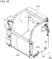
- FIG. 42 is a perspective view showing the structure of the wrapped-coin storage member 382 in the lift unit 380.
- FIG. 43 is a perspective view showing the structure of the wrapped-coin storage member 382 shown in FIG. 42 as seen from another angle.
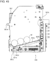
- FIG. 44 and FIG. 45 are vertical cross-sectional views showing the internal structure of the wrapped-coin storage member 382 shown in FIG. 42 and FIG. 43 .
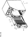
- FIG. 46 is a perspective view showing the structure of a lifting and lowering mechanism for lifting and lowering the wrapped-coin storage member 382 in the lift unit 380.
- FIG. 47 is a perspective view showing the structure of the lifting and lowering mechanism shown in FIG. 46 as seen from another angle.
- the lift unit 380 includes the wrapped-coin storage member 382 in which wrapped coin rolls dispensed by the dispensing mechanisms 319 of the respective storage units 310 are stored.
- the wrapped-coin storage member 382 is able to move up and down between an upper position near the shutter 390 and each of positions facing the dispensing mechanisms 319 provided in the respective storage units 310 as indicated by an arrow in FIG. 32 .
- the wrapped-coin storage member 382 moves to the position facing this dispensing mechanism 319. As shown in FIG.
- the wrapped-coin storage member 382 is provided with the dispensed wrapped-coin detecting unit 384 which detects a wrapped coin roll dispensed by the dispensing mechanism 319 of each storage unit 310.
- the dispensed wrapped-coin detecting unit 384 is composed of an optical sensor or the like having a photoemitter and a photodetector, for example.
- a placement unit 382a on which wrapped coin rolls are to be placed is provided in a bottom portion of the wrapped-coin storage member 382.
- An upper face of the placement unit 382a is inclined with respect to the horizontal plane. More specifically, the placement unit 382a is rotatable about a shaft 382b extending in the horizontal direction.
- An end (lower end portion) of a spring 382f serving as a biasing member is connected to an end portion, of the placement unit 382a, opposite to an end portion thereof on which the shaft 382b is provided, while the other end (upper end portion) of the spring 382f is attached to the wrapped-coin storage member 382.
- the end portion, of the placement unit 382a, opposite to the end portion on which the shaft 382b is provided is pulled upward by the spring 382f, whereby the placement unit 382a is maintained at a predetermined position (specifically, the position shown in FIG. 44 ) when no wrapped coin roll is placed thereon.
- a wrapped coin roll is placed on the placement unit 382a, the placement unit 382a is turned downward about the shaft 382b against a biasing force caused by the spring 382f, and the placement unit 382a moves to a position as shown in FIG. 45 .
- a detection plate 382c is provided on the end portion, of the placement unit 382a, opposite to the end portion on which the shaft 382b is provided.
- a detection sensor 382d such as an interrupter is provided in the vicinity of the detection plate 382c.
- the detection sensor 382d detects the detection plate 382c when the placement unit 382a moves from the position shown in FIG. 44 to the position shown in FIG. 45 .
- the detection sensor 382d is composed of an optical sensor or the like having a photoemitter and a photodetector (in FIG. 44 and FIG. 45 , the position where the photoemitter and the photodetector are provided is represented by reference numeral 382e).
- the detection plate 382c and the detection sensor 382d constitute a wrapped-coin detection unit for detecting wrapped coin rolls placed on the placement unit 382a. That is, when no wrapped coin roll is placed on the placement unit 382a, the placement unit 382a is lifted upward by the spring 382f to be maintained at the position shown in FIG. 44 , and the detection plate 382c is not detected by the detection sensor 382d.
- the placement unit 382a When a wrapped coin roll is placed on the placement unit 382a, the placement unit 382a turns downward about the shaft 382b against the biasing force caused by the spring 382f, and the placement unit 382a moves to the position shown in FIG. 45 , whereby the detection plate 382c is detected by the detection sensor 382d.
- a light reflection member such as a mirror is provided on an internal rear side 382k of the wrapped-coin storage member 382.
- wrapped coin rolls stored in the wrapped-coin storage member 382 in particular, wrapped coin rolls that have moved frontward in the wrapped-coin storage member 382 due to the placement unit 382a being inclined, are reflected in the light reflection member on the internal rear side 382k of the wrapped-coin storage member 382, and an operator can see, by means of the light reflection member, whether or not wrapped coin rolls remain inside the wrapped-coin storage member 382.
- the operator can see whether or not wrapped coin rolls remain inside the wrapped-coin storage member 382 by seeing the light reflection member.
- a packing member 382m formed of rubber or the like, having a rectangular parallelepiped shape and being horizontally extendable, is adhered to an uppermost portion, of the wrapped-coin storage member 382, on the front side of the wrapped-coin outlet. Due to the presence of the packing member 382m, loose coins are prevented from entering the gap between the rear face of the upper door 14 and the wrapped-coin storage member 382 from the opening 61 of the upper door 14 (refer to FIG. 5 ) when the wrapped-coin storage member 382 is located at the upper position (the solid-line position in FIG. 32 ), while the wrapped-coin storage member 382 is smoothly moved up and down.
- the lift unit 380 is provided with a circulating belt 386 extending in the vertical direction, and the wrapped-coin storage member 382 is attached to the circulating belt 386 through a joint member 382j.
- the drive motor 387 one of a plurality of pulleys over which the circulating belt 386 is stretched is provided with a drive motor 387, and the drive motor 387 is rotatable in both the forward and backward directions.
- the drive motor 387 allows the circulating belt 386 to circularly move in both the forward and backward directions.
- a guide member 388 extending in the vertical direction is provided, and the guide member 388 guides the lifting and lowering operation of the wrapped-coin storage member 382.
- a plurality of detection plates 389a are provided so as to correspond to the respective storage units 310, and each detection plate 389a detects that the wrapped-coin storage member 382 is located at the position opposed to the dispensing mechanism 319 of the corresponding storage unit 310.
- a detection sensor 382g such as an interrupter for detecting each detection plate 389a is provided on a side face of the wrapped-coin storage member 382.
- the detection sensor 382g is composed of an optical sensor or the like having a photoemitter and a photodetector.
- a retaining plate 389b for causing the wrapped-coin storage member 382 to be retained at the position opposite to the dispensing mechanism 319 of each storage unit 310 is provided, and the retaining plate 389b has a plurality of recessed portions corresponding to the respective storage units 310.
- a lock plate 382h and a drive unit 382i such as a solenoid are provided on the side face of the wrapped-coin storage member 382.
- the lock plate 382h enters each of the recessed portions formed in the retaining plate 389b to stop the wrapped-coin storage member 382, and the drive unit 382i actuates the lock plate 382h.
- the drive unit 382i actuates the lock plate 382h to cause the lock plate 382h to enter a specified recessed portion of the retaining plate 389b, whereby the wrapped-coin storage member 382 is stopped and retained.
- FIG. 48 is a perspective view showing the structure of the money changer 10 shown in FIG. 1 in the state where the wrapped-coin dispensing apparatus 300 is pulled out frontward from the outer housing 12 after the lower door 16 and the upper door 14 are opened.
- FIG. 49 is a perspective view showing the structure of the money changer 10 in the state where the door 314 of a certain storage unit 310 (specifically, the uppermost storage unit 310) among the plurality of storage units 310 of the wrapped-coin dispensing apparatus 300 is opened from the state shown in FIG. 48 . As shown in FIG. 48 and FIG.
- a partition member 18 for separating the area where the wrapped-coin dispensing apparatus 300 is housed from the area where the loose coin depositing and dispensing apparatus 100 is housed is provided inside the outer housing 12 of the money changer 10.
- the door 314 of a storage unit 310 is opened in the wrapped-coin dispensing apparatus 300 as shown in FIG. 49
- the door 314 comes into contact with the partition member 18 so that the wrapped-coin dispensing apparatus 300 cannot be housed in the outer housing 12.
- the wrapped-coin dispensing apparatus 300 cannot be housed in the outer housing 12 unless the door 314 of each storage unit 310 is completely closed in the wrapped-coin dispensing apparatus 300.
- FIG. 50 is a side view of the wrapped-coin dispensing apparatus 300 shown in FIG. 31 , showing the internal structure of each storage unit 310.
- FIG. 51 is a side view of the wrapped-coin dispensing apparatus 300 shown in FIG. 31 in the state where the door 314 of each storage unit 310 is opened. In FIG. 51 , the door 314 opened from the uppermost storage unit 310a and the door 314 opened from the second storage unit 310b from the top are not illustrated in order to make the internal structure of each storage unit 310 easy to view.
- the height of the storage area of each storage unit 310 differs between the side where the dispensing mechanism 319 is provided and the side opposite to the side where the dispensing mechanism 319 is provided.
- the distance between a ceiling portion 310c on the side where the dispensing mechanism 319 is provided and the bottom face 312 of the storage unit 310a is greater than that in the other portion, whereby the height of the storage area on the side where the dispensing mechanism 319 is provided in the storage unit 310a is greater than the height of the storage area on the side opposite to the side where the dispensing mechanism 319 is provided.
- a storage area regulating portion 310d for reducing the height of the storage area is provided in an upper portion, of each storage unit 310b, on the side opposite to the side where the dispensing mechanism 319 is provided.
- the height of the storage area on the side where the dispensing mechanism 319 is provided is greater than the height of the storage area on the side opposite to the side where the dispensing mechanism 319 is provided.
- the height of the storage area on the side where the dispensing mechanism 319 is provided is greater than the height of the storage area on the side opposite to the side where the dispensing mechanism 319 is provided, it is possible to avoid a situation that too many wrapped coin rolls are stored in each of the storage units 310a and 310b, thereby avoiding a situation that the wrapped coin rolls stored in each of the storage units 310a and 310b are in the state as shown in FIG. 41 and a plurality of wrapped coin rolls cause so-called bridge phenomenon between the bottom face 312 and the gate unit 330 of each of the storage units 310a and 310b.
- a plate-shaped wrapped-coin insertion preventing member 317 for preventing a wrapped coin roll from being inserted into an upper portion of the storage area from the outside of the storage unit 310a is provided in an upper portion, on the dispensing mechanism 319 side, of the side face of the uppermost storage unit 310a among the plurality of storage units 310. Since the wrapped-coin insertion preventing member 317 is provided, when an operator replenishes the storage area of the storage unit 310a with wrapped coin rolls from the outside of the storage unit 310a, the wrapped coin rolls are prevented from being stacked in the vicinity of the ceiling portion 310c shown in FIG. 50 . Further, as shown in FIG.
- a plate-shaped wrapped-coin insertion preventing member 318 for preventing wrapped coin rolls from being inserted into an upper portion of the storage area from the outside is also provided in an upper portion, on the dispensing mechanism 319 side, of the side face of each of the storage units 310b other than the uppermost storage unit 310a. Since the wrapped-coin insertion preventing member 318 is provided, when the operator replenishes the storage area of each storage unit 310b with wrapped coin rolls from the outside of the storage unit 310b, the wrapped coin rolls are prevented from being stacked in the vicinity of a ceiling portion 310e shown in FIG. 50 .
- the wrapped coin rolls stacked in the storage unit 310a or 310b may be in the state as shown in FIG. 41 and a plurality of wrapped coin rolls may cause so-called bridge phenomenon between the bottom face 312 and the gate unit 330 of the storage unit 310a or 310b.
- the wrapped-coin insertion preventing member 317, 318 for preventing wrapped coin rolls from being inserted in the upper portion of the storage area from the outside of the storage unit 310a, 310b is provided, occurrence of bridge phenomenon as shown in FIG. 41 is avoided.
- a side wall on the far side of each of the storage units 310a and 310b is composed of two joined wall parts 315a and 315b formed of resin, for example. Joined portions of these wall parts 315a and 315b each have a comb-teeth shape, and the comb-teeth shaped portions of the wall parts 315a and 315b are mutually meshed. Since the side wall on the far side of each of the storage units 310a and 310b is formed of two wall parts 315a and 315b, production of the wall parts 315a and 315b by resin molding is facilitated.
- the joined portions of the wall parts 315a and 315b each have a comb-teeth shape and the comb-teeth shaped joint portions of the wall parts 315a and 315b are mutually meshed, wrapped coin rolls inside the storage unit 310a or 310b are prevented from being caught by the joined portions of the wall parts 315a and 315b.
- the two hinges 316 are provided at the lower edge portion of the door 314, and the door 314 is openably and closably attached to the side face of the housing 302 of the wrapped-coin dispensing apparatus 300 by means of the hinges 316, as described above.
- the door 314 is provided with a projecting member 314m that projects upward from an upper edge of the door 314, and a plate-shaped magnet member 314n provided on the rear side of the projecting member 314m.
- the main body of the storage unit 310 is formed of an iron-based member, for example.
- the main body of the storage unit 310 and the projecting member 314m of the door 314 are attracted to each other by a magnetic force of the magnetic member 314n provided on the door 314, whereby the door 314 can be fixed in its closed state.
- a plate-shaped magnetic member (not shown) may be provided on a portion, of the main body of the storage unit 310, corresponding to the projecting member 314m of the door 314, and this projecting member 314m may be formed of an iron-based member, for example.
- the main body of the storage unit 310 and the projecting member 314m of the door 314 are attracted to each other by a magnetic force of the magnetic member provided on the main body of the storage unit 310, whereby the door 314 can be fixed in the closed state.
- FIG. 53 is a side view showing the structure of the door fixing member 323.
- FIG. 54 is a side view showing the structure when the door 314 is opened from the state shown in FIG. 53.
- FIG. 55 is a side view showing, in detail, the structure of the door fixing member 323 shown in FIG. 53 .
- FIG. 56 is a side view showing the state when the door is opened by turning the door fixing member 323 shown in FIG. 55 upward.
- the door fixing member 323 is turnable about a shaft 323a provided in the main body of the storage unit 310.
- the shaft 323a is provided with a torsion spring 323b as a biasing member that biases the door fixing member 323 to keep the door fixing member 323 at a position (the position shown in FIG. 53 ) in which the door 314 is held in a closed state.
- the torsion spring 323b applies a force to the door fixing member 323 to turn the door fixing member 323 in the counter clockwise direction in FIG. 55 or FIG. 56 about the shaft 323a.
- a pressing member 323c for pressing the upper edge of the door 314 is attached to the door fixing member 323.
- the pressing member 323c is inclined with respect to the surface of the sheet of FIG. 55 or FIG. 56 so that its upper side is positioned frontward relative to its lower side.
- a force that maintains the door fixing member 323 in the position shown in FIG. 53 is applied to the door fixing member 323 by the torsion spring 323b, and the pressing member 323c presses the upper edge of the door 314, whereby the door 314 is held in a closed state.
- an operator when opening the door 314, an operator, with his/her fingers, turns the door fixing member 323 in the clockwise direction about the shaft 323a.
- the pressing member 323c of the door fixing member 323 is retracted upward from the upper edge of the door 314 as shown in FIG. 56 , whereby the operator can open the door 314.
- the torsion spring 323b applies, to the door fixing member 323, a force to turn the door fixing member 323 in the counter clockwise direction about the shaft 323a, whereby the door fixing member 323 returns to the original position.
- the pressing member 323c of the door fixing member 323 comes into contact with the upper edge of the door 314.
- the pressing member 323c is inclined with respect to the plane of the drawings of FIG. 55 or FIG. 56 so that its upper side is positioned frontward relative to its lower side. Therefore, when the pressing member 323c is pushed by the upper edge of the door 314, the pressing member 323c moves upward, and the door fixing member 323 turns in the clockwise direction in FIG. 55 or FIG. 56 about the shaft 323a.
- the pressing member 323c of the door fixing member 323 is retracted upward from the upper edge of the door 314. Thereafter, the door fixing member 323 returns to the position shown in FIG.
- each storage unit 310 is provided with denomination indicating parts 306 and 308 such as labels indicating the denomination of wrapped coin rolls to be stored in the storage unit 310.
- the denomination indicating part 306 is adhered to the front face of the door 314, while the denomination indicating part 308 is adhered to a portion, to the left of the door fixing member 323, of the main body of the storage unit 310.
- the denomination indicating parts 306 and 308 thus provided enable the operator to recognize at a glance which denomination of wrapped coin rolls should be replenished in the storage unit 310 in both cases where the door 314 is closed and the door 314 is opened.
- a wrapped-coin insertion method indicating part 304 such as a label indicating how to insert wrapped coin rolls from the outside of the storage unit 310 into the storage area of the storage unit 310 is provided on the side face of the wrapped-coin dispensing apparatus 300.
- the content of the wrapped-coin insertion method indicating part 304 will be described with reference to FIG. 60 .
- the top image indicates a correct method of inserting wrapped coin rolls into the storage unit 310, while a second image and a bottom image each indicate an incorrect method of inserting wrapped coin rolls into the storage unit 310.
- the second image indicates that, when inserting wrapped coin rolls, any wrapped coin roll should not be stacked at the rear side of the wrapped-coin insertion preventing member 317 or the wrapped-coin insertion preventing member 318 provided on the dispensing mechanism 319 side of the storage unit 310.
- the bottom chart indicates that, when inserting wrapped coin rolls, a space should not be formed anywhere among the wrapped coin rolls stacked in multiple layers in the storage area of the storage unit 310.
- a scale (not shown) indicating the number of wrapped coin rolls stored at the bottom of the storage area may be provided on the bottom face 312 (storage face) of the storage unit 310.
- the door 314 may be formed of, for example, a transparent member or a semi-transparent member so that the operator can see the inside of the storage unit 310, and a scale (not shown) indicating the number of wrapped coin rolls stored at the bottom of the storage area may be provided on the transparent or semi-transparent member of the door 314.
- a scale is provided on the bottom face 312 of the storage unit 310 or on the door 314, the operator can know the approximate number of the stored wrapped coin rolls when replenishing wrapped coin rolls into the storage unit 310.
- a fixing unit (lock unit) 400 for fixing (locking) the wrapped-coin dispensing apparatus 300 to the inside of the outer housing 12 is provided inside the outer housing 12 of the money changer 10.
- the structure of the fixing unit 400 will be described in detail with reference to FIG. 57 through FIG. 59 .
- FIG. 57 is a perspective view showing the structure of the fixing unit 400.
- FIG. 58 is a side view of the fixing unit 400 shown in FIG. 57 .
- FIG. 59 is a perspective view showing the operation of canceling the fixed state of the wrapped-coin dispensing apparatus 300 due to the fixing unit 400, by pushing downward a handle 402 provided in the fixing unit 400 shown in FIG. 57 .
- the fixing unit 400 includes a bar-shaped member 404 that is turnable about a shaft 406 extending in the horizontal direction.
- a handle 402 to be operated by an operator is provided at one of the end portions of the bar-shaped member 404.
- the handle 402 By operating the handle 402, it disengages the fixing unit 400 so the wrapped-coin dispensing apparatus 300 is free to be pulled out frontward from the inside of the outer housing 12 of the money changer 10. More specifically, after the upper door 14 and the lower door 16 of the outer housing 12 are opened, the fixing unit 400 is disengaged so the wrapped-coin dispensing apparatus 300 is free to be pulled out frontward from the inside of the outer housing 12 of the money changer 10.
- the fixing unit 400 is attached to the wrapped-coin dispensing apparatus 300, and when the wrapped-coin dispensing apparatus 300 is pulled out from the inside of the outer housing 12, the wrapped-coin dispensing apparatus 300 and the fixing unit 400 are integrally moved.
- the handle 402 of the fixing unit 400 is provided above the wrapped-coin dispensing apparatus 300, on the front side in the depth direction of the outer housing 12.
- a pin member 410 is provided on the other end portion, of the bar-shaped member 404, opposite to the end portion where the handle 402 is provided.
- the pin member 410 can be engaged with a member-to-be-engaged 420 fixedly provided in the outer housing 12. More specifically, a recessed portion 422 is formed at an upper edge of the member-to-be-engaged 420 provided in the outer housing 12, and the pin member 410 is fitted in the recessed portion 422 (refer to FIG. 57 and FIG. 58 ). Further, a spring 408 that pulls the bar-shaped member 404 upward is provided on the bar-shaped member 404 at a position closer to the handle 402 than to the shaft 406.
- the operator pushes the handle 402 downward to turn the bar-shaped member 404 about the shaft 406 as represented by a solid line in FIG. 59 .
- the pin member 410 moves upward, and comes out from the recessed portion 422 of the member-to-be-engaged 420 provided in the outer housing 12.
- the wrapped-coin dispensing apparatus 300 can be pulled out frontward from the inside of the outer housing 12.
- an inclined portion 424 having a slanted surface inclined with respect to the vertical direction is provided frontward of the recessed portion 422 at an upper edge of the member-to-be-engaged 420. Therefore, when the wrapped-coin dispensing apparatus 300 pulled out from the outer housing 12 is returned to the inside of the outer housing 12, the pin member 410 of the fixing unit 400 comes into contact with the inclined portion 424 of the member-to-be-engaged 420. When the wrapped-coin dispensing apparatus 300 is further pushed into the outer housing 12, the bar-shaped member 404 turns about the shaft 406 so that the pin member 410 is raised along the slanted surface of the inclined portion 424. Thereafter, the pin member 410 is fitted in the recessed portion 422 of the member-to-be-engaged 420, whereby the wrapped-coin dispensing apparatus 300 is fixed (locked) inside the outer housing 12.
- the fixing unit 400 even when a large number of wrapped coin rolls are stored in each storage unit 310 of the wrapped-coin dispensing apparatus 300 and thereby the weight of the wrapped-coin dispensing apparatus 300 is increased, the wrapped-coin dispensing apparatus 300 can be pulled out frontward from the inside of the outer housing 12 by pushing the handle 402 downward to cancel the fixed state of the wrapped-coin dispensing apparatus 300 due to the fixing unit 400, and then pulling the handle 402 frontward. Therefore, the work burden on the operator can be reduced.
- the handle 402 since the handle 402 has both the function of canceling the fixed state of the wrapped-coin dispensing apparatus 300 due to the fixing unit 400, and the function of pulling out the wrapped-coin dispensing apparatus 300 frontward from the inside of the outer housing 12, space saving can be achieved.
- FIG. 61 is a perspective view showing the structure in which the back plate 19 of the money changer 10 shown in FIG. 1 is attached to the outer housing 12.
- FIG. 62 is an enlarged perspective view showing, in an enlarged manner, the structure in which the back plate 19 shown in FIG. 61 is attached to the outer housing 12.
- FIG. 63 is a perspective view showing the structure of the money changer 10 shown in FIG. 1 as seen from the rear side.
- an attachment member 19a is fixed by means of the screws 19c to the inner side of the back plate 19, and the attachment member 19a is also fixed to a ceiling plate of the outer housing 12 by means of screws 19b.
- the back plate 19 is fixed to the outer housing 12 from the inner side by means of the screws 19c, and cannot be detached from the outside of the outer housing 12.
- a plurality of attachment members are fixed by means of screws on the inner side of the back plate 19, and these attachment members are fixed to the side plates, the bottom plate, and the like of the outer housing 12 by means of screws.
- the pair of handles 19d is externally provided on the back plate 19 to allow an operator to easily perform a detaching operation of the back plate 19.
- the operator detaches the back plate 19 from the attachment member 19a by removing the screws 19c from the inside of the outer housing 12, and thereafter, holds the pair of handles 19d with both hands to carry the back plate 19.
Landscapes
- Physics & Mathematics (AREA)
- General Physics & Mathematics (AREA)
- Cash Registers Or Receiving Machines (AREA)
- Control Of Vending Devices And Auxiliary Devices For Vending Devices (AREA)
Abstract
Description
- The present invention relates to a wrapped-coin dispensing apparatus configured to dispense wrapped coin rolls stored in a machine body to the outside of the machine body.
- Various types of wrapped-coin dispensing apparatus for dispensing wrapped coin rolls stored in a machine body to the outside of the machine body have been used to date. For example, wrapped-coin dispensing apparatus disclosed in Japanese Patent No.
3857001 JP38570018 2002-109607 JP2002-109607A U.S. Patent No. 7111754 (US7111754B ), andU.S. Patent No. 7571833 (US75718338 - In such a wrapped-coin dispensing apparatus, in the case where a plurality of wrapped coin rolls are stored in a storage unit so as to be stacked in multiple layers, if the height of a storage area in the storage unit is uniform, the number of wrapped coin rolls stored in the storage unit might be too great. In this case, the wrapped coin rolls stacked in multiple layers in the storage unit may cause so-called bridge phenomenon, and the wrapped coin rolls stored in the storage unit cannot be dispensed by a dispensing mechanism.
- The present invention has been made in view of such circumstances. In the present invention, the height of the storage area is made different between the side, in the storage unit, where the dispensing mechanism is provided, and the side opposite to the side where the dispensing mechanism is provided. Thus, the number of wrapped coin rolls stored in the storage unit is prevented from being too great, thereby preventing the wrapped coin rolls stored in the storage unit from causing so-called bridge phenomenon.
- A wrapped-coin dispensing apparatus according to the present invention includes a storage unit and a lift unit. The storage unit is provided with a dispensing mechanism configured to dispense a plurality of wrapped coin rolls which are stored on a storage face inclined with respect to a horizontal plane so as to be stacked in a direction in which the wrapped coin rolls run along the inclined storage face. The dispensing mechanism dispenses the wrapped coin rolls, one by one, from a side closest to a portion, at a lowest height level, of the storage face. The lift unit includes a wrapped-coin storage member configured to store, therein, the wrapped coin rolls dispensed from the storage unit by the dispensing mechanism. The lift unit is movable in a vertical direction. The storage unit includes a pair of side walls which form a storage area for the wrapped coin rolls therebetween. At least one of the pair of side walls is configured as an openable and closable door through which the wrapped coin rolls are taken in and out from the storage unit. The height of the storage area differs between a side of the storage unit where the dispensing mechanism is provided, and a side opposite to the side where the dispensing mechanism is provided.
- In the wrapped-coin dispensing apparatus according to the present invention, a storage area regulating portion configured to reduce the height of the storage area may be provided in an upper portion of the storage unit on the side opposite to the side where the dispensing mechanism is provided.
- In the wrapped-coin dispensing apparatus according to the present invention, a wrapped-coin insertion preventing portion configured to prevent wrapped coin rolls from being inserted into an upper portion of the storage area from the outside of the storage unit may be provided in an upper portion at a side face of the storage unit, on the side where the dispensing mechanism is provided.
- In the wrapped-coin dispensing apparatus according to the present invention, the storage unit may be provided with a denomination indicating part which indicates a denomination of wrapped coin rolls to be stored in the storage unit.
- In the wrapped-coin dispensing apparatus according to the present invention, a wrapped-coin insertion method indicating part which indicates a method of inserting wrapped coin rolls into the storage area from the outside of the storage unit may be provided.
- In the wrapped-coin dispensing apparatus according to the present invention, the side wall of the storage unit, other than the door, may be divided into a plurality of members, each member having a comb teeth shaped joint portion, and the comb teeth shaped joint portions of the members may be mutually meshed.
- In the wrapped-coin dispensing apparatus according to the present invention, the dispensing mechanism may include: a rotor configured to rotate about an axial center extending in a direction orthogonal to a direction of inclination of the storage unit and in a horizontal direction, and have at least two recessed portions, each recessed portion receiving, one by one, the wrapped coin rolls stored in the storage unit; and a drive unit configured to rotate the rotor about the axial center. A gear configured to transmit a rotational drive force to the rotor may be provided on a side of the rotor, and the gear may be provided with a plurality of through-holes corresponding to the recessed portions of the rotor.
- In the wrapped-coin dispensing apparatus according to the present invention, a scale indicating the number of wrapped coin rolls stored at the bottom of the storage area may be provided on the storage face of the storage unit.
- In the wrapped-coin dispensing apparatus according to the present invention, the door may be configured such that an operator is able to visually observe the inside of the storage unit, and the door may be provided with a scale indicating the number of wrapped coin rolls stored at the bottom of the storage area.
-
-
FIG. 1 is a perspective view showing the external appearance of a money changer according to an embodiment of the present invention. -
FIG. 2 is a perspective view showing the internal structure of the money changer shown inFIG. 1 with a lower door provided at a front face of an outer housing being opened. -
FIG. 3 is a perspective view showing the internal structure of the money changer shown inFIG. 1 with an upper door provided at the front face of the outer housing being additionally opened from the state shown inFIG. 2 . -
FIG. 4 is a top view showing the structure of the lower door, as seen from above, in the money changer shown inFIG. 1 etc. -
FIG. 5 is a perspective view showing the structure of the upper door in the money changer shown inFIG. 1 etc. -
FIG. 6 is a vertical cross-sectional view of the upper door shown inFIG. 5 . -
FIG. 7 is a vertical cross-sectional view showing, in an enlarged manner, a small article placement part of the upper door shown inFIG. 6 . -
FIG. 8 is a front view of the upper door shown inFIG. 5 . -
FIG. 9 is a vertical cross-sectional view of the upper door shown inFIG. 5 . -
FIG. 10 is a schematic block diagram schematically showing the structure of the money changer shown inFIG. 1 . -
FIG. 11 is a perspective view showing the external appearance of a loose coin depositing and dispensing apparatus provided inside the outer housing of the money changer shown inFIG. 1 . -
FIG. 12 is a side view showing the internal structure of the loose coin depositing and dispensing apparatus shown inFIG. 11 . -
FIG. 13 is a front view showing the internal structure of the loose coin depositing and dispensing apparatus shown inFIG. 11 . -
FIG. 14 is a perspective view showing the structure of a coin insertion mechanism provided in the loose coin depositing and dispensing apparatus shown inFIG 11 . -
FIG. 15 is a top view showing the structure of the coin insertion mechanism shown inFIG. 14 . -
FIG. 16 is a vertical cross-sectional view of the coin insertion mechanism shown inFIG. 15 , taken along a direction of arrows A-A inFIG. 15 , showing the state before a coin receiving section is inclined. -
FIG. 17 is a vertical cross-sectional view of the coin insertion mechanism shown inFIG. 15 , taken along the direction of arrows A-A inFIG. 15 , showing the state after the coin receiving section is inclined. -
FIG. 18 is a vertical cross-sectional view of the coin insertion mechanism shown inFIG. 15 , taken along a direction of arrows B-B inFIG. 15 . -
FIG. 19 is a vertical cross-sectional view of the coin insertion mechanism shown inFIG. 15 , taken along a direction of arrows C-C inFIG. 15 . -
FIG. 20 is a perspective view showing the state where a coin receiving unit is opened upward in the coin insertion mechanism shown inFIG. 15 . -
FIG. 21 is a perspective view showing the structure of a foreign material receiving unit provided in the coin insertion mechanism shown inFIG. 15 . -
FIG. 22 is a perspective view showing the structure of a collection box which collects coins from the loose coin depositing and dispensing apparatus shown inFIG. 11 . -
FIG. 23 is a side view showing the state where the collection box shown inFIG. 22 is conveyed by pulling a cord hooked on the collection box. -
FIG. 24 is a perspective view showing the structure, on the bottom face, of the collection box shown inFIG. 22 . -
FIG. 25 is a vertical cross-sectional view showing the structure of a rear wheel provided on the collection box shown inFIG. 24 . -
FIG. 26 is a side view schematically showing the state where the collection box shown inFIG. 22 is housed inside a collection box housing disposed below the housing of the loose coin depositing and dispensing apparatus. -
FIG. 27 is a side view schematically showing the state where the collection box shown inFIG. 22 is in the process of being pulled out from the collection box housing disposed below the housing of the loose coin depositing and dispensing apparatus. -
FIG. 28 is a top view showing the internal structure of the collection box shown inFIG. 22 as seen from above, with an upper lid thereof being opened. -
FIG. 29 is a perspective view showing the external appearance of a loose banknote depositing and dispensing apparatus provided inside the outer housing of the money changer shown inFIG. 1 etc. -
FIG. 30 is a side view showing the internal structure of the loose banknote depositing and dispensing apparatus shown inFIG. 29 . -
FIG. 31 is a perspective view showing the external appearance of a wrapped-coin dispensing apparatus provided inside the outer housing of the money changer shown inFIG. 1 etc. -
FIG. 32 is a side view showing the internal structure of the wrapped-coin dispensing apparatus shown inFIG. 31 . -
FIG. 33 is a perspective view showing the structure of a dispensing mechanism provided in each of storage units in the wrapped-coin dispensing apparatus shown inFIG. 31 . -
FIG. 34 is a side view of the dispensing mechanism shown inFIG. 33 . -
FIG. 35 is a side view showing, in detail, components such as a rotor of the dispensing mechanism shown inFIG. 34 . -
FIG. 36 is a side view showing, in detail, the components such as the rotor of the dispensing mechanism shown inFIG. 34 . -
FIG. 37 is a side view showing an operation of dispensing wrapped coin rolls stored in the storage unit by means of the dispensing mechanism in the wrapped-coin dispensing apparatus shown inFIG. 31 . -
FIG. 38 is a side view showing an operation of dispensing the wrapped coin rolls stored in the storage unit by means of the dispensing mechanism in the wrapped-coin dispensing apparatus shown inFIG. 31 . -
FIG. 39 is a side view showing an operation of dispensing the wrapped coin rolls stored in the storage unit by means of the dispensing mechanism in the wrapped-coin dispensing apparatus shown inFIG. 31 . -
FIG. 40 is a side view showing an operation of dispensing the wrapped coin rolls stored in the storage unit by means of the dispensing mechanism in the wrapped-coin dispensing apparatus shown inFIG. 31 . -
FIG. 41 is a side view showing the state where the so-called bridge phenomenon of wrapped coin rolls occurs in the vicinity of the dispensing mechanism in the storage unit of the wrapped-coin dispensing apparatus shown inFIG. 31 . -
FIG. 42 is a perspective view showing the structure of a wrapped-coin storage member in a lift unit of the wrapped-coin dispensing apparatus shown inFIG. 31 . -
FIG. 43 is a perspective view showing the structure of the wrapped-coin storage member shown inFIG. 42 , as seen from another angle. -
FIG. 44 is a vertical cross-sectional view showing the internal structure of the wrapped-coin storage member shown inFIG. 42 andFIG. 43 , in the state where no wrapped coin roll is stored therein. -
FIG. 45 is a vertical cross-sectional view showing the internal structure of the wrapped-coin storage member shown inFIG. 42 andFIG. 43 , in the state where wrapped coin rolls are stored therein. -
FIG. 46 is a perspective view showing the structure of a lifting and lowering mechanism which causes the wrapped-coin storage member in the lift unit of the wrapped-coin dispensing apparatus shown inFIG. 31 to move up and down. -
FIG. 47 is a perspective view showing the structure of the lifting and lowering mechanism shown inFIG. 46 , as seen from another angle. -
FIG. 48 is a perspective view showing the structure of the money changer shown inFIG. 1 in the state where the wrapped-coin dispensing apparatus is pulled out frontward from the outer housing after the lower door and the upper door are opened. -
FIG. 49 is a perspective view showing the structure in the state where a door of a storage unit of the wrapped-coin dispensing apparatus is opened from the state shown inFIG. 48 . -
FIG. 50 is a side view showing the internal structure of each of the storage units of the wrapped-coin dispensing apparatus shown inFIG. 31 . -
FIG. 51 is a side view showing the state where the doors of the storage units of the wrapped-coin dispensing apparatus shown inFIG. 31 are opened. -
FIG. 52 is a diagram showing the structure of the door in the wrapped-coin dispensing apparatus shown inFIG. 31 . -
FIG. 53 is a side view showing the structure of a door fixing member (door lock member) for fixing (locking) the door in the wrapped-coin dispensing apparatus shown inFIG. 31 in the closed state. -
FIG. 54 is a side view showing the structure in the case where the door is opened from the state shown inFIG. 53 . -
FIG. 55 is a side view showing the structure of the door fixing member shown inFIG. 53 in detail. -
FIG. 56 is a side view showing the state where the door is opened by turning the door fixing member shown inFIG. 55 upward. -
FIG. 57 is a perspective view showing the structure of a fixing unit (lock unit) for fixing (locking) the wrapped-coin dispensing apparatus shown inFIG. 31 inside the outer housing. -
FIG. 58 is a side view of the fixing unit shown inFIG. 57 . -
FIG. 59 is a perspective view showing an operation of canceling the fixed state of the wrapped-coin dispensing apparatus due to the fixing unit, by pushing a handle provided in the fixing unit shown inFIG. 57 downward. -
FIG. 60 is a diagram showing the content of a wrapped-coin insertion method indicating part provided on a side face of the housing of the wrapped-coin dispensing apparatus shown inFIG. 31 . -
FIG. 61 is a perspective view showing the structure of the money changer shown inFIG. 1 , in which a back plate is attached to the outer housing. -
FIG. 62 is an enlarged perspective view showing, in an enlarged manner, the structure shown inFIG. 61 in which the back plate is attached to the outer housing. -
FIG. 63 is a perspective view showing the structure of the money changer shown inFIG. 1 , as seen from the rear side. - Hereinafter, an embodiment of the present invention will be described with reference to the drawings.
FIGS. 1 to 63 are diagrams illustrating the structure of a money changer according to the present embodiment. The money changer according to the present embodiment is installed in a lobby of a financial facility or the like, and is used for money change processes performed thereon through operations of customers. More specifically, the money changer according to the present embodiment is able to perform, as money change processes, a forward money change process in which the denomination of dispensed money is smaller than the denomination of deposited money, and a reverse money change process in which the denomination of dispensed money is larger than the denomination of deposited money. In the money changer according to the present embodiment, when the above money change processes are performed, there is a case where a service charge for money changing is deducted from the amount of the deposited money and the remaining amount of money is dispensed. Further, in the money changer according to the present embodiment, new banknotes of the same total amount as that of deposited old banknotes, or of an amount after deduction of a service charge for money changing from the total amount, may be dispensed. Alternatively, fit notes of the same total amount as that of deposited unfit notes, or of an amount after deduction of a service charge for money changing from the total amount, may be dispensed. Still alternatively, brand-new notes (so-called new bills) of the same total amount as that of deposited circulated notes, or of an amount after deduction of a service charge for money changing from the total amount, may be dispensed. - First, the overall structure of the money changer according to the present embodiment will be described with reference to
FIG. 1 through FIG. 10 .FIG. 1 is a perspective view showing the external appearance of the money changer according to the present embodiment.FIG. 2 is a perspective view showing the internal structure of the money changer shown inFIG. 1 with a lower door provided at a front face of an outer housing being opened.FIG. 3 is a perspective view showing the internal structure of the money changer shown inFIG. 1 with an upper door provided at the front face of the outer housing being additionally opened from the state shown inFIG. 2 .FIG. 4 is a top view showing the structure of the lower door, as seen from above, in the money changer shown inFIG. 1 etc.FIG. 5 is a perspective view showing the structure of the upper door in the money changer shown inFIG. 1 etc.FIG. 6 is a vertical cross-sectional view of the upper door shown inFIG. 5 .FIG. 7 is a vertical cross-sectional view showing, in an enlarged manner, a small article placement part of the upper door shown inFIG. 6 .FIG. 8 is a front view of the upper door shown inFIG. 5 .FIG. 9 is a vertical cross-sectional view of the upper door shown inFIG. 5 .FIG. 10 is a schematic block diagram schematically showing the structure of the money changer shown inFIG. 1 . - As shown in
FIG. 1 etc., themoney changer 10 according to the present embodiment includes anouter housing 12 having a substantially rectangular parallelepiped shape. Inside theouter housing 12, a loose coin depositing and dispensingapparatus 100, a loose banknote depositing and dispensingapparatus 200, and a wrapped-coin dispensing apparatus 300 are arranged side by side in a horizontal direction. The loose coin depositing and dispensingapparatus 100, the loose banknote depositing and dispensingapparatus 200, and the wrapped-coin dispensing apparatus 300 each can be pulled out frontward in the horizontal direction to be taken out from the inside of theouter housing 12 independently from the other apparatuses. - Further, the
upper door 14 and thelower door 16 are provided at the front face of theouter housing 12 of themoney changer 10. As shown inFIG. 3 , theupper door 14 can be opened upward from the closed state shown inFIG. 1 , and thelower door 16 can be laterally opened from the closed state shown inFIG. 1 . In the present embodiment, each of theupper door 14 and thelower door 16 constitutes a part of theouter housing 12. At the left and right sides of an upper part of theupper door 14, light-emitting diodes (LED) 90 and 92 serving as state notifying units are provided, respectively. The light-emittingdiodes money changer 10 is in. - As shown in
FIG. 10 , themoney changer 10 according to the present embodiment is provided with acontrol unit 20 which is connected to each of the loose coin depositing and dispensingapparatus 100, the loose banknote depositing and dispensingapparatus 200, and the wrapped-coin dispensing apparatus 300 to control theseapparatuses FIG. 1 through FIG. 3 , an operation/display unit 40 composed of, for example, a touch panel or the like is provided on the back side of theupper door 14 of themoney changer 10, and the operation/display unit 40 is connected to the control unit 20 (refer toFIG. 10 ). The operation/display unit 40 displays information about the handling condition of money, the inventory amount of money, and the like in each of theapparatuses control unit 20 through operations performed on the operation/display unit 40. In addition, as shown inFIG. 5 , theupper door 14 is provided with anopening 60 which allows the operator to operate the operation/display unit 40 and see the displayed content on the operation/display unit 40. Themoney changer 10 may be provided with a display unit composed of a monitor or the like, and an operation unit composed of a keyboard, operation keys, or the like, which units are provided separately from each other instead of the operation/display unit 40 composed of a touch panel or the like. - In the present embodiment, the operation/
display unit 40 is vertically moved in conjunction with an opening/closing operation of theupper door 14. That is, when theupper door 14 is opened upward from a front face upper portion of the outer housing 12 (refer toFIG. 3 ), the operation/display unit 40 is moved upward from the position thereof at which theupper door 14 is closed. Thus, when the loose coin depositing and dispensingapparatus 100 or the wrapped-coin dispensing apparatus 300 is pulled out frontward from the inside of theouter housing 12 after theupper door 14 is opened, the operation/display unit 40 is moved upward so that the loose coin depositing and dispensingapparatus 100 or the wrapped-coin dispensing apparatus 300 does not come into contact with the operation/display unit 40. Since the operation/display unit 40 is vertically moved in conjunction with the opening/closing operation of theupper door 14, the space inside theouter housing 12 can be utilized more effectively than in the case where the position of the operation/display unit 40 is fixed. Moreover, the operability of the operation/display unit 40 is improved. In addition, when the loose coin depositing and dispensingapparatus 100 or the wrapped-coin dispensing apparatus 300 is pulled out, the operation of pulling out theapparatus display unit 40. The operation/display unit 40 is not limited to the above structure that is vertically moved in conjunction with the opening/closing operation of theupper door 14. The operation/display unit 40 may have alternative structures as follows. That is, the operation/display unit 40 may be moved in the left-right direction or the front-rear direction in conjunction with the opening/closing operation of theupper door 14, or may be pivotally moved in conjunction with the opening/closing operation of theupper door 14. - As shown in
FIG. 5 , theupper door 14 is provided with: an opening 62 through which the operator inserts coins into a coin insertion mechanism 110 (described later) of the loose coin depositing and dispensingapparatus 100; anopening 64 through which the operator takes out coins from a coin outlet 172 (described later) of the loose coin depositing and dispensingapparatus 100; anopening 63 through which the operator inserts banknotes into adepositing unit 252 of the loose banknote depositing and dispensingapparatus 200 and takes out banknotes from adispensing unit 260 of the loose banknote depositing and dispensingapparatus 200; and anopening 61 through which the operator takes out wrapped coin rolls from a wrapped-coin storage member 382 of alift unit 380 in the wrapped-coin dispensing apparatus 300. On the rear side (the inner side of the apparatus) of theupper door 14 at positions near therespective openings money changer 10 through gaps between the rear side of theupper door 14 andhousings respective apparatuses - As shown in
FIG. 10 , acard reader 42 and aprinter 44 are connected to thecontrol unit 20 of themoney changer 10. Thecard reader 42 reads an ID card or the like possessed by the operator to perform identification of the operator. Theprinter 44 functions as a printing unit which prints, on a receipt or the like, information about the handling condition of money, the inventory amount of money, and the like in each of theapparatuses FIG. 1 , a card insertion port through which a card is inserted into thecard reader 42 and a receipt dispensing port through which a receipt is dispensed from theprinter 44 are provided on theupper door 14 of themoney changer 10. Further, thecard reader 42 adopted in the present embodiment does not take therein an ID card or the like inserted into the card insertion port, but returns the ID card or the like to the outside from the card insertion port after reading the card. Using thiscard reader 42 prevents the operator, who has inserted the ID card or the like into the card insertion port, from forgetting to take out the ID card or the like from the card insertion port. - Further, as shown in
FIG. 2 , on a lower portion of an inner face of thelower door 16, a projectingmember 50 projecting inward from the inner face of thelower door 16 is provided. The structure of this projectingmember 50 will be described with reference toFIG. 4 . As shown inFIG. 4 , the projectingmember 50 has a slantedsurface 50a inclined with respect to the inner face of thelower door 16. Since the projectingmember 50 has the slantedsurface 50a, even when the wrapped-coin dispensing apparatus 300 is pulled out frontward in the horizontal direction from the inside of theouter housing 12 in the state where thelower door 16 is not completely opened from a front face lower portion of theouter housing 12 of themoney changer 10, a front end portion of the wrapped-coin dispensing apparatus 300 hits theslanted surface 50a of the projectingmember 50, whereby thelower door 16 is opened in accordance with the operation of pulling out the wrapped-coin dispensing apparatus 300. Thus, the wrapped-coin dispensing apparatus 300 can be smoothly pulled out without being hindered by thelower door 16. Further, as shown inFIG. 2 andFIG. 4 , the projectingmember 50 is provided with a projection-shapedbuffer member 52 formed of rubber cushion or the like. Since thebuffer member 52 is provided on the projectingmember 50, even when thelower door 16 is closed in the state where acollection box 180 described later is not completely housed in acollection box housing 103 provided below thehousing 102 of the loose coin depositing and dispensingapparatus 100, the projection-shapedbuffer member 52, such as rubber cushion, provided on the projectingmember 50 comes into contact with thecollection box 180, whereby thecollection box 180 can be pushed into thecollection box housing 103. At this time, since thebuffer member 52 is formed of rubber cushion or the like, the front face of thecollection box 180 is prevented from being damaged. - In the present embodiment, and shown in
FIG. 5 , a smallarticle placement part 70 on which small articles such as a wrapped coin roll taken out from the wrapped-coin dispensing apparatus 300 are placed is provided on the front face of the outer housing 12 (in particular , the upper door 14), and a raisedportion 72 for preventing the small articles such as a wrapped coin roll placed on the smallarticle placement part 70 from falling is provided at the front side of the smallarticle placement part 70. The structure of the smallarticle placement part 70 will be described in detail with reference toFIG. 5 through FIG. 7 . As described above,FIG. 5 is a perspective view showing the structure of theupper door 14 of themoney changer 10 shown inFIG. 1 ,FIG. 6 is a vertical cross-sectional view of theupper door 14 shown inFIG. 5 , andFIG. 7 is a vertical cross-sectional view showing, in an enlarged manner, the smallarticle placement part 70 of theupper door 14 shown inFIG. 6 . - As shown in
FIG. 5 , the smallarticle placement part 70 is provided over the whole area in the width direction of the outer housing 12 (in particular, the upper door 14), and the smallarticle placement part 70 has a smallarticle placement surface 70a extending along a horizontal plane (refer toFIG. 6 andFIG. 7 ). In addition, as shown inFIG. 6 andFIG. 7 , the raisedportion 72 is formed so as to be raised from the smallarticle placement surface 70a at a position on the front side of the smallarticle placement part 70. This raisedportion 72 is also provided over the whole area in the width direction of theouter housing 12. (in particular, the upper door 14). Since the smallarticle placement part 70 is provided, the operator can temporarily place a small article, such as a wrapped coin roll taken out from the wrapped-coin dispensing apparatus 300, on the smallarticle placement part 70, in order to assist the operator. Further, since the smallarticle placement part 70 has the raisedportion 72, the small article placed on the smallarticle placement surface 70a of the smallarticle placement part 70 is prevented from falling. - Further, as shown in
FIG. 8 andFIG. 9 , on theupper door 14, at positions on the both sides of theopening 62 through which the operator inserts coins into the coin insertion mechanism 110 (described later) of the loose coin depositing and dispensingapparatus 100, slantedsurfaces opening 62. Specifically, as shown inFIG. 8 andFIG. 9 , the slantedsurface 80 provided to the left of theopening 62 is inclined with respect to the horizontal plane so as to be gradually increased in height with distance from theopening 62 in the leftward direction, and the slantedsurface 82 provided to the right of theopening 62 is inclined with respect to the horizontal plane so as to be gradually increased in height with distance from theopening 62 in the rightward direction. Since the slanted surfaces 80 and 82 are provided, coins accidentally dropped from thecoin insertion mechanism 110 when the operator inserts coins into thecoin insertion mechanism 110 of the loose coin depositing and dispensingapparatus 100 are prevented from moving toward theopening 61 and theopening 63 located at the both sides of theopening 62, and therefore, the dropped coins are prevented from being accidentally input to thedepositing unit 252 of the loose banknote depositing and dispensingapparatus 200 and/or the wrapped-coin storage member 382 of thelift unit 380 in the wrapped-coin dispensing apparatus 300. - Next, the structure of the loose coin depositing and dispensing
apparatus 100 in themoney changer 10 according to the present embodiment will be described with reference toFIG. 11 through FIG. 28 .FIG. 11 is a perspective view showing the external appearance of the loose coin depositing and dispensingapparatus 100.FIG. 12 is a side view showing the internal structure of the loose coin depositing and dispensingapparatus 100 shown inFIG. 11 .FIG. 13 is a front view showing the internal structure of the loose coin depositing and dispensingapparatus 100 shown inFIG. 11 .FIGS. 14 to 21 illustrate the structure of thecoin insertion mechanism 110 provided in the loose coin depositing and dispensingapparatus 100 shown inFIG. 11 .FIGS. 22 to 28 illustrate the structure of thecollection box 180 housed in thecollection box housing 103 provided adjacent to an external lower portion of thehousing 102 of the loose coin depositing and dispensingapparatus 100 shown inFIG. 11 . - As shown in
FIG. 11 through FIG. 13 , the loose coin depositing and dispensingapparatus 100 is provided with: thehousing 102 having a substantially rectangular parallelepiped shape; thecoin insertion mechanism 110 for inserting coins from the outside to the inside of thehousing 102; and an escrowing/feeding mechanism 130 to which coins inserted into thehousing 102 by the loose coin depositing and dispensingapparatus 100 are transported and escrowed, and which feeds the escrowed coins one by one. The structure of thecoin insertion mechanism 110 will be described later in detail. The escrowing/feeding mechanism 130 includes: arotary disk 132 which is inclined at a predetermined angle with respect to the vertical direction and is rotated in the inclined position; and acover member 134 which forms acoin escrow space 133 for escrowing coins therein, between asurface 132b of therotary disk 132 and thecover member 134. - In an upper portion of the
housing 102, a depositingtransport unit 120 is provided which transports, one by one, the coins fed from the escrowing/feeding mechanism 130, and the depositingtransport unit 120 is provided with a recognition unit 122 which recognizes the denomination, authenticity, fitness, version (old/new), and the like of the coins transported by the depositingtransport unit 120. - Further, the depositing
transport unit 120 is provided with anendless belt 120p. Theendless belt 120p is stretched over a plurality of pulleys. Theendless belt 120p is circularly moved in a counter clockwise direction inFIG. 12 by a motor mounted to one pulley. Further, a plurality of projecting members (not shown) are provided on theendless belt 120p at equal intervals, and one coin is hooked by one projecting member, so that the coins are transported on a transport surface one by one. - In the
housing 102, a plurality of (for example six, as shown infigure 12 ) storing/feedingmechanisms 150 are provided below the depositingtransport unit 120. Coins are transported from the depositingtransport unit 120 to the storing/feeding mechanisms 150 throughchutes 126 by sortingunits 124 provided in the depositingtransport unit 120 , on the basis of the recognition result of the coins processed by the recognition unit 122.The transported coins are then stored in the storing/feeding mechanism 150. The depositingtransport unit 120 is provided with areject sorting unit 127 which is a sorting unit for reject coins. A coin which is recognized to be a counterfeit coin by the recognition unit 122 is transported to acoin outlet 172 described later through a chute (not shown) for reject coins by thereject sorting unit 127. Further, separately from thecoin outlet 172, a reject unit (not shown) for rejecting the reject coins to the outside of the apparatus may be provided in the vicinity of thecoin outlet 172. In this case, a coin recognized to be a counterfeit coin by the recognition unit 122 is transported by thereject sorting unit 127, as a reject coin, to the reject unit through the chute for reject coins. - Each storing/
feeding mechanism 150 feeds out, one by one, the coins stored in the storing/feeding mechanism 150. More specifically, each storing/feeding mechanism 150 includes: arotary disk 152 which is inclined at a predetermined angle with respect to the vertical direction and is rotated in the inclined position; and acover member 154 which forms acoin storage space 153 for storing coins therein, between asurface 152b of therotary disk 152 and thecover member 154. - The loose coin depositing and dispensing
apparatus 100 is provided with thecoin outlet 172 through which coins are dispensed to the outside of thehousing 102. A dispensingtransport unit 170 for transporting the coins fed out from each storing/feeding mechanism 150 to thecoin outlet 172 is provided in thehousing 102. The dispensingtransport unit 170 includes: a firstdispensing transport section 170a which is provided below the storing/feeding mechanisms 150 and extends substantially in the horizontal direction; and a seconddispensing transport section 170b which transports the coins transported from the firstdispensing transport section 170a to thecoin outlet 172. The dispensingtransport unit 170 is composed of anendless belt 170p stretched over a plurality of pulleys. Theendless belt 170p is circularly moved by a motor mounted to one pulley in both a clockwise direction and a counter clockwise direction inFIG. 12 . Further, a plurality of projecting members (not shown) are provided on theendless belt 170p at equal intervals, and one or more coins are hooked by one projecting member, so that the coins are transported one or more at a time by theendless belt 170p. - The
collection box 180 used as an overflow coin storage unit is provided below the dispensingtransport unit 170. Thecollection box 180 can be pulled out frontward in the horizontal direction from thecollection box housing 103 provided below thehousing 102. When theendless belt 170p is circularly moved in the clockwise direction inFIG. 12 , coins are transported from the firstdispensing transport section 170a of the dispensingtransport unit 170 to thecollection box 180. After the coins are stored in thecollection box 180, thecollection box 180 is pulled out frontward from thecollection box housing 103, whereby the coins can be collected together with thecollection box 180. The structure of thecollection box 180 will be described later in detail. - As shown in
FIG. 12 , the loose coin depositing and dispensingapparatus 100 is provided with anoverflow chute 125 for directly transporting coins from the depositingtransport unit 120 to the dispensingtransport unit 170 without transporting the coins through the storing/feeding mechanisms 150. Further, the depositingtransport unit 120 is provided with anoverflow sorting unit 123 for sorting coins to be transported to theoverflow chute 125, separately from thesorting unit 124 for sorting coins to be transported to thechute 126 corresponding to each storing/feeding mechanism 150. A lower end portion of theoverflow chute 125 is located above theendless belt 170p of the dispensingtransport unit 170. In this structure, the coins sorted by theoverflow sorting unit 123 among the coins transported by the depositingtransport unit 120 are transported onto theendless belt 170p of the dispensingtransport unit 170 through theoverflow chute 125. - Since the
overflow chute 125 is provided, when the storing/feeding mechanism 150 corresponding to the denomination of a coin recognized by the recognition unit 122 is full of coins, the coin of the denomination for which the storing/feeding mechanism 150 is full of coins is sorted by theoverflow sorting unit 123 to be transported onto theendless belt 170p of the dispensingtransport unit 170 by theoverflow chute 125, without suspending transport of coins by the depositingtransport unit 120. Then, the coin transported onto theendless belt 170p of the dispensingtransport unit 170 by theoverflow chute 125 is transported to thecollection box 180 by theendless belt 170p. In the loose coin depositing and dispensingapparatus 100 having the above structure, even when the storing/feeding mechanism 150 corresponding to the denomination of a coin recognized by the recognition unit 122 is full of coins, this coin can be transported to thecollection box 180 without suspending transport of coins by the depositingtransport unit 120, whereby reduction in the coin handing speed can be avoided. - Next, the structure of the
coin insertion mechanism 110 in the loose coin depositing and dispensingapparatus 100 will be described in detail with reference toFIG. 14 through FIG. 21 .FIG. 14 is a perspective view showing the structure of thecoin insertion mechanism 110.FIG. 15 is a top view showing the structure of thecoin insertion mechanism 110 shown inFIG. 14 . Each ofFIG. 16 andFIG. 17 is a vertical cross-sectional view of thecoin insertion mechanism 110 shown inFIG. 15 , taken along the direction of arrows A-A inFIG. 15 .FIG. 18 is a vertical cross-sectional view of thecoin insertion mechanism 110 shown inFIG. 15 , taken along the direction of arrows B-B inFIG. 15 .FIG. 19 is a vertical cross-sectional view of thecoin insertion mechanism 110 shown inFIG. 15 , taken along the direction of arrows C-C inFIG. 15 .FIG. 20 is a perspective view showing the state where acoin receiving unit 140 is opened upward in thecoin insertion mechanism 110 shown inFIG. 15 .FIG. 21 is a perspective view showing the structure of a foreignmaterial receiving unit 112 provided in thecoin insertion mechanism 110 shown inFIG. 15 . - As shown in
FIG. 14 through FIG. 19 , thecoin insertion mechanism 110 for inserting coins from the outside to the inside of thehousing 102 of the loose coin depositing and dispensingapparatus 100 includes: acoin receiving section 111 which receives coins inserted into a coin inlet provided at an upper face of thehousing 102, and removes a foreign material such as a clip mixed with the received coins; and acoin feeding unit 115 which feeds the coins transported from thecoin receiving section 111 to the inside of thehousing 102 of the loose coin depositing and dispensingapparatus 100, and transports the coins to the escrowing/feeding mechanism 130. In addition, achute 113 which forms a coin transport path for transporting the coins received by thecoin receiving section 111 to thecoin feeding unit 115 is provided between thecoin receiving section 111 and thecoin feeding unit 115. As shown inFIG. 20 , thecoin receiving section 111 and thechute 113 are provided in thecoin receiving unit 140 which can be opened upward from the upper portion of thehousing 102 of the loose coin depositing and dispensingapparatus 100, and the operator can access thecoin feeding unit 115 by opening thecoin receiving unit 140 upward. Therefore, when, for example, failure in feeding coins occurs in thecoin feeding unit 115, the operator can remove coins jammed in thecoin feeding unit 115 by opening thecoin receiving unit 140 upward as shown inFIG. 20 . - The
coin receiving section 111 is composed of a tray including afirst tray portion 111a and asecond tray portion 111b, and the coins inserted into the coin inlet are received by this tray. As shown inFIG. 15 etc., thesecond tray portion 111b is provided adjacent to thechute 113. Thefirst tray portion 111a is inclined with respect to the horizontal plane so that an upper face thereof extends obliquely downward toward thesecond tray portion 111b, and thefirst tray portion 111a is not adjacent to thechute 113. Therefore, the coins received by thefirst tray portion 111a are first transported to thesecond tray portion 111b and then transported from thesecond tray portion 111b to thechute 113. - As shown in
FIG. 16 andFIG. 17 , thefirst tray portion 111a and thesecond tray portion 111b in thecoin receiving section 111 are integrally turnable about ashaft 111d extending in the horizontal direction. More specifically, thefirst tray portion 111a and thesecond tray portion 111 b are integrally turnable between a coin receiving position at which the coins inserted into the coin inlet are received as shown inFIG. 16 and a coin transport position at which the coins received by thefirst tray portion 111 a and thesecond tray portion 111b are transported to thechute 113 as shown inFIG. 17 . When no force is applied to thefirst tray portion 111 a and thesecond tray portion 111 b, thefirst tray portion 111 a and thesecond tray portion 111 b are at the coin receiving position shown inFIG. 16 by their own weights. After the coins inserted into the coin inlet are received by thefirst tray portion 111 a and thesecond tray portion 111 b, if the operator manually lifts thefirst tray portion 111a and thesecond tray portion 111b integrally so that thefirst tray portion 111 a and thesecond tray portion 111 b are turned about theshaft 111 d to be moved to the coin transport position shown inFIG. 17 , the coins received by thefirst tray portion 111a and thesecond tray portion 111b are transported to thechute 113 by their own weights. In the present embodiment, thecoin insertion mechanism 110 is not limited to the above structure in which thefirst tray portion 111 a and thesecond tray portion 111 b are manually turned about theshaft 111d. In another structure according to a modification, thecoin insertion mechanism 110 may be provided with a drive motor (not shown) for turning thefirst tray portion 111a and thesecond tray portion 111b about theshaft 111d. In still another structure, the operator may manually transport the coins received by thefirst tray portion 111 a and thesecond tray portion 111 b to thechute 113. - In the present embodiment, a step is formed between the
first tray portion 111 a and thesecond tray portion 111 b so that an edge portion, on thesecond tray portion 111b side, of thefirst tray portion 111a is slightly higher in height than an edge portion, on thefirst tray portion 111 a side, of thesecond tray portion 111 b. Thus, when thefirst tray portion 111 a and thesecond tray portion 111 b are moved to the coin transport position shown inFIG. 17 , firstly, the coins received by thesecond tray portion 111b are transported to thechute 113 and thereafter the coins received by thefirst tray portion 111 a are transported to thechute 113 through thesecond tray portion 111b. This structure avoids a situation that the coins received by thefirst tray portion 111 a and thesecond tray portion 111 b are transported to thechute 113 at one time and cause a trouble such as a coin jam. - Further, in the present embodiment, as shown in
FIG. 16 , the upper face of thesecond tray portion 111 b is inclined with respect to the horizontal plane so that the height thereof is gradually reduced with distance from theshaft 111d, when thesecond tray portion 111b is in the coin receiving position. Thus, even when the operator puts a foreign material such as a clip together with coins on thefirst tray portion 111a or thesecond tray portion 111b, transport of the foreign material from thesecond tray portion 111 b to thechute 113 is prevented as long as thefirst tray portion 111 a and thesecond tray portion 111 b are in the coin receiving position (in other words, unless the operator manually lifts thefirst tray portion 111a and thesecond tray portion 111b integrally to turn them about theshaft 111d), and consequently, transport of the foreign material to the escrowing/feeding mechanism 130 is prevented. - Further, as shown in
FIG. 15 etc., each of thefirst tray portion 111a and thesecond tray portion 111b is provided with a plurality ofholes 111c for eliminating foreign materials. The size of eachhole 111 c is smaller than the size of coins to be handed by the loose coin depositing and dispensingapparatus 100. As shown inFIG. 16 andFIG. 17 , the foreignmaterial receiving unit 112 for receiving foreign materials that have passed through theholes 111c is provided below thefirst tray portion 111a and thesecond tray portion 111b. - In the present embodiment, the foreign
material receiving unit 112 is detachable from thecoin insertion mechanism 110. The structure of the foreignmaterial receiving unit 112 is shown inFIG. 21 in detail. The foreignmaterial receiving unit 112 is formed of, for example, plastic or the like. As shown inFIG. 21 , aprojection 112a for mounting the foreignmaterial receiving unit 112 to thecoin insertion mechanism 110 is provided on one of side faces of the foreignmaterial receiving unit 112. Although not shown inFIG. 21 , a projection for mounting the foreignmaterial receiving unit 112 to thecoin insertion mechanism 110 is also provided on a side face, of the foreignmaterial receiving unit 112, opposite to the side face on which theprojection 112a is provided. In addition, the position of the foreignmaterial receiving unit 112 is not changed even when thecoin receiving unit 140 is opened upward as shown inFIG. 20 . The foreignmaterial receiving unit 112 can be detached from thecoin insertion mechanism 110 in the state where thecoin receiving unit 140 is opened upward. Specifically, theprojection 112a is detached from thecoin insertion mechanism 110 by pressing the side face, of the foreignmaterial receiving unit 112, on which theprojection 112a is provided. Then, the side face, of the foreignmaterial receiving unit 112, on which theprojection 112a is provided is lifted upward and slightly turned, and the foreignmaterial receiving unit 112 is slightly displaced rightward, whereby the projection (not shown) provided on the side face, of the foreignmaterial receiving unit 112, opposite to the side face on which theprojection 112a is provided is detached from thecoin insertion mechanism 110. Thereafter, the foreignmaterial receiving unit 112 is lifted further upward to detach the foreignmaterial receiving unit 112 from thecoin insertion mechanism 110. - As shown in
FIG. 16 andFIG. 17 , thechute 113 includes afirst guide portion 113a forming a bottom face of the coin transport path, and asecond guide portion 113b forming an upper face of the coin transport path. The coins transported from thecoin receiving section 111 to thechute 113 are conveyed so as to pass through an area between thefirst guide portion 113a and thesecond guide portion 113b to be transported to thecoin feeding unit 115. As shown inFIG. 16 andFIG. 17 , thefirst guide portion 113a forming the bottom face of the coin transport path is inclined with respect to the horizontal plane so as to extend obliquely downward toward thecoin feeding unit 115 from thecoin receiving section 111. Therefore, the coins transported from thecoin receiving section 111 to thechute 113 are transported to thecoin feeding unit 115 by their own weights. Further, as shown inFIG. 16 andFIG. 17 , in the vicinity of thesecond guide portion 113b, a wrapped-cointransport regulating unit 113c is provided so as to be spaced apart from thefirst guide portion 113a. The distance between thefirst guide portion 113a and the wrapped-cointransport regulating unit 113c is smaller than the diameter of coins to be handled by the loose coin depositing and dispensingapparatus 100, and the coins transported from thecoin receiving section 111 to thechute 113 move toward thesecond guide portion 113b while sliding on thefirst guide portion 113a by their own weights, not in a standing state but in a laterally lying state. Since the wrapped-cointransport regulating unit 113c is provided, even when the operator mistakenly inserts a wrapped coin roll into the coin inlet of the loose coin depositing and dispensingapparatus 100, the wrapped coin roll does not pass through the space between thefirst guide portion 113a and the wrapped-cointransport regulating unit 113c but is caught by the wrapped-cointransport regulating unit 113c, thereby preventing the wrapped coin roll from being transported to thecoin feeding unit 115 described later. When the wrapped coin roll is caught by the wrapped-cointransport regulating unit 113c, the operator can take out the wrapped coin roll by putting his/her hand into the coin inlet. - As shown in
FIG. 16 andFIG. 17 , ashutter 114 for selectively blocking transport of coins from thecoin receiving section 111 to thecoin feeding unit 115 is openably and closably provided on thechute 113. Thisshutter 114 is movable between a closed position at which theshutter 114 is located between thefirst guide portion 113a and thesecond guide portion 113b of thechute 113 and closes the coin transport path as shown inFIG. 16 , and an opened position at which theshutter 114 is retracted from the coin transport path to be located above thesecond guide portion 113b as shown inFIG. 17 . When theshutter 114 is in the closing position shown inFIG. 16 , the coins transported from thecoin receiving section 111 to thechute 113 are blocked by theshutter 114 and are not transported to thecoin feeding unit 115. In the vicinity of theshutter 114 in thechute 113, a coin passage detecting sensor (not shown) for detecting passage of coins is provided. - As shown in
FIG. 19 , thecoin feeding unit 115 includes atransport belt 115a stretched over a plurality ofpulleys 115b, and the coins transported from thechute 113 to thecoin feeding unit 115 are received on thetransport belt 115a. A drive motor (not shown) is connected to one of the plurality ofpulleys 115b, and thepulley 115b connected to the drive motor is driven to rotate by the drive motor, whereby thetransport belt 115a can be circularly moved in both the clockwise direction and the counter clockwise direction inFIG. 19 . When thetransport belt 115a is circularly moved in the clockwise direction inFIG. 19 , the coins transported from thechute 113 to thecoin feeding unit 115 are transported rightward inFIG. 19 on thetransport belt 115a, and drop off from an end portion of thetransport belt 115a as indicated by an arrow inFIG. 19 to be transported to the escrowing/feeding mechanism 130. - Further, as shown in
FIG. 19 , a coin transportamount restricting member 116 for restricting the amount of coins to be transported from thecoin feeding unit 115 to the escrowing/feeding mechanism 130 is provided above an end portion, of thetransport belt 115a, on the escrowing/feeding mechanism 130 side (i.e., on the right side inFIG. 19 ). The coin transportamount restricting member 116 is formed of a plate-shaped elastic body (specifically, a material having flexibility) such as urethane rubber, and a lower end portion of the coin transportamount restricting member 116 is slightly separated upward from an upper face of thetransport belt 115a. Since the coin transportamount restricting member 116 is provided above thetransport belt 115a, it is possible to avoid a situation that a large number of coins present on thetransport belt 115a drop off from the end portion of thetransport belt 115a at one time like an avalanche and are transported to the escrowing/feeding mechanism 130. Further, the coin transportamount restricting member 116 is swingable about ashaft 116a, between a position indicated by a solid line inFIG. 19 and a position indicated by a two-dot chain line inFIG. 19 . Thus, when coins received on thetransport belt 115a are transported to the escrowing/feeding mechanism 130 by thetransport belt 115a, even if some of the coins are caught between a side wall of thecoin feeding unit 115 and the coin transportamount restricting member 116 and do not drop from thetransport belt 115a, the caught coins can be separated from the coin transportamount restricting member 116 to be received on thetransport belt 115a or can be dropped off toward the escrowing/feeding mechanism 130 side, by causing the coin transportamount restricting member 116 to swing. - Next, the operation of the
coin insertion mechanism 110 having the above structure will be described. When an operator inputs, to the operation/display unit 40, an instruction to start a loose-coin depositing process, theshutter 114 provided on thechute 113 is opened. In addition, thetransport belt 115a of thecoin feeding unit 115 is circularly moved in the clockwise direction inFIG. 19 . When the operator inserts coins into the coin inlet provided at the upper face of thehousing 102, the coins are received by thefirst tray portion 111 a and/or thesecond tray portion 111b of thecoin receiving section 111. At this time, foreign materials mixed with the coins are transported to the foreignmaterial receiving unit 112 through theholes 111c for eliminating foreign materials. Thereafter, when the operator manually lifts up thefirst tray portion 111 a and thesecond tray portion 111b integrally so that thefirst tray portion 111a and thesecond tray portion 111 b are turned about theshaft 111 d and moved to the coin transport position as shown inFIG. 17 , the coins received by thefirst tray portion 111a and/or thesecond tray portion 111 b are transported to thechute 113 by their own weights and then transported from thechute 113 to thecoin feeding unit 115. The coins transported to thecoin feeding unit 115 are received on thetransport belt 115a. Then, thetransport belt 115a is circularly moved in the clockwise direction inFIG. 19 , whereby the coins on thetransport belt 115a drop off from the end portion of thetransport belt 115a as indicated by an arrow inFIG. 19 to be transported to the escrowing/feeding mechanism 130. - When a predetermined period of time has passed after the coin passage detecting sensor (not shown) provided in the
chute 113 no longer detects passage of coins, it is determined that the coins received by thefirst tray portion 111a and/or thesecond tray portion 111b of thecoin receiving section 111 have been transported to the escrowing/feeding mechanism 130. In this case, theshutter 114 is closed to block transport of coins from thecoin receiving section 111 to thecoin feeding unit 115. Further, at this time, thetransport belt 115a is circularly moved for a predetermined period of time in a direction opposite to the direction of transporting the coins to the escrowing/feeding mechanism 130 (i.e., counter clockwise direction inFIG. 19 ), and the coin transportamount restricting member 116 swings so that the coins in contact with the coin transportamount restricting member 116 are separated from the coin transportamount restricting member 116. Thus, the coins caught between the side wall of thecoin feeding unit 115 and the coin transportamount restricting member 116 can be separated from the coin transportamount restricting member 116 and received on thetransport belt 115a. Then, thetransport belt 115a is circularly moved for a predetermined period of time in the direction opposite to the coin transporting direction toward the escrowing/feeding mechanism 130, and thereafter is again circularly moved in the coin transporting direction toward the escrowing/feeding mechanism 130 (clockwise direction inFIG. 19 ). Thus, the coins separated from the coin transportamount restricting member 116 and received on thetransport belt 115a are transported to the escrowing/feeding mechanism 130. - Next, the structure of the
collection box 180 will be described in detail with reference toFIG. 22 through FIG. 28 .FIG. 22 is a perspective view showing the structure of thecollection box 180.FIG. 23 is a side view showing the state where acord 183 is hooked on thecollection box 180 shown inFIG 22 , and thecord 183 is pulled to convey thecollection box 180.FIG. 24 is a perspective view showing the structure, on a bottom face side, of thecollection box 180 shown inFIG. 22 .FIG. 25 is a vertical cross-sectional view showing the structure of arear wheel 187 provided on thecollection box 180 shown inFIG. 24 .FIG. 26 is a side view schematically showing the state where thecollection box 180 shown inFIG. 22 is housed inside thecollection box housing 103 disposed below thehousing 102 of the loose coin depositing and dispensingapparatus 100.FIG. 27 is a side view schematically showing the state where thecollection box 180 shown inFIG. 22 is in the middle of being pulled out from the inside of thecollection box housing 103.FIG. 28 is a top view showing the internal structure of thecollection box 180 shown inFIG. 22 as seen from above, with anupper lid 181 being opened. - First, the overall structure of the
collection box 180 will be described with reference toFIG. 22 etc. As shown inFIG. 22 etc., thecollection box 180 has a substantially rectangular parallelepiped shape. At the bottom of thecollection box 180, a pair of left and rightfront wheels 186 and a pair of left and rightrear wheels 187 are provided at the front and the rear, respectively. In addition, thecollection box 180 is provided with theupper lid 181. The operator can take out the coins stored in thecollection box 180 by opening theupper lid 181. Theupper lid 181 is provided with anopening 181a through which the coins transported from theendless belt 170p of the dispensingtransport unit 170 pass, and theopening 181 a is provided with a shutter for closing theopening 181a. When thecollection box 180 is pulled out from thecollection box housing 103, the opening 181 a is closed by the shutter. On the other hand, when thecollection box 180 is housed into thecollection box housing 103, the shutter automatically opens the opening 181 a. - The
collection box housing 103 for housing thecollection box 180 is provided below thehousing 102 of the loose coin depositing and dispensing apparatus 100 (refer toFIG. 26 andFIG. 27 ). Thiscollection box housing 103 is attached to a lower face of thehousing 102 of the loose coin depositing and dispensingapparatus 100. Regardless of whether thecollection box 180 is housed in thecollection box housing 103 or is pulled out from thecollection box housing 103, thecollection box housing 103 can be pulled out frontward, integrally with thehousing 102 of the loose coin depositing and dispensingapparatus 100, from the inside of theouter housing 12 of themoney changer 10. - In the present embodiment, as shown in
FIG. 23 , when thecord 183 is hooked on a front-side end portion of thecollection box 180 and pulled, thecollection box 180 can be pulled out from thecollection box housing 103 and/or thecollection box 180 pulled out from thecollection box housing 103 can be conveyed. More specifically, as shown inFIG. 22 andFIG. 23 , thecollection box 180 is provided with acord housing 182 for housing thecord 183. Thecord housing 182 is provided at a position on the front side in the depth direction of thehousing 102 when thecollection box 180 is housed in thecollection box housing 103. Further, thecord housing 182 is provided with through-holes 184 on which thecord 183 taken out from thecord housing 182 is hooked. The through-holes 184 are formed at both side faces of thecord housing 182 when thecollection box housing 103 is viewed from the front. - As described above, in the present embodiment, the operator pulls out the
collection box 180 from thecollection box housing 103 and/or conveys thecollection box 180 pulled out from thecollection box housing 103, by hooking thecord 183 on the front-side end portion of thecollection box 180 and pulling thecord 183. Therefore, when the operator pulls out, from thecollection box housing 103, or conveys theheavy collection box 180 in which a large number of coins are stored, the burden on the operator can be reduced as compared to the case where the operator conveys thecollection box 180 with his/her hands holding thecollection box 180. - Further, in the present embodiment, the
front wheels 186 and therear wheels 187 have different heights. Specifically, as shown inFIG. 24 and FIG. 25 , there is an opening in the vicinity of eachrear wheel 187 at the bottom face of thecollection box 180, and a half of therear wheel 187 is in the opening so as to be lower in height than thefront wheel 186. More specifically, eachrear wheel 187 is supported by awheel support member 187b so as to rotate about ashaft 187a, and thewheel support member 187b is mounted on ametal plate 187c provided inside thecollection box 180. Thus, therear wheel 187 is half inserted in the opening formed at the bottom face of thecollection box 180, and therefore is lower in height than thefront wheel 186. - In the present embodiment, as shown in
FIG. 26 andFIG. 27 , the bottom face of thecollection box housing 103 is substantially flush with a floor surface on which themoney changer 10 is installed. Thus, the operator can smoothly perform the action of pulling out thecollection box 180 from thecollection box housing 103 and the action of housing thecollection box 180 in thecollection box housing 103. - In the present embodiment, since the
collection box housing 103 is provided below thehousing 102 of the loose coin depositing and dispensingapparatus 100, even when thelower door 16 of themoney changer 10 is opened but theupper door 14 thereof is not opened as shown inFIG. 2 , thecollection box 180 can be pulled out from thecollection box housing 103. Thus, the operator can pull out thecollection box 180 from thecollection box housing 103 without opening theupper door 14, whereby the work burden on the operator can be reduced. - The height of the bottom face of the
collection box housing 103 varies depending on the position in the depth direction (rightward direction inFIG. 26 andFIG. 27 ) of thehousing 102. Specifically, the height of thecollection box housing 103 is set so that the internal bottom face of thecollection box 180 is in the horizontal state when thecollection box 180 is housed in thecollection box housing 103. More specifically, thecollection box housing 103 includes: apedestal portion 104 on which therear wheels 187 of thecollection box 180 ride when thecollection box 180 is housed in thecollection box housing 103; and aninclined portion 105 which has a slanted surface inclined with respect to the horizontal plane, and connects the bottom face of thehousing 102 to thepedestal portion 104. Since therear wheels 187 of thecollection box 180 ride on thepedestal portion 104 when thecollection box 180 is housed in thecollection box housing 103, the internal bottom face of thecollection box 180 is in the horizontal state although the height of thefront wheels 186 is different from the height of therear wheels 187 as shown inFIG. 26 . On the other hand, when thecollection box 180 is pulled out from thecollection box housing 103, therear wheels 187 of thecollection box 180 run on thepedestal portion 104 and come into contact with the floor surface through theinclined portion 105. Thus, in the present embodiment, since the height of thecollection box housing 103 is set so that the internal bottom face of thecollection box 180 is in the horizontal state when thecollection box 180 is housed in thecollection box housing 103, the coins transported from theendless belt 170p of the dispensingtransport unit 170 to thecollection box 180 can be uniformly stacked over the entirety of the internal area of thecollection box 180. - As shown in
FIG. 28 , asheet 188 formed of an elastic material such as rubber is spread on aninner bottom face 180a of thecollection box 180. Thesheet 188 provided on theinner bottom face 180a of thecollection box 180 can reduce impact sound that is generated when the coins drop from theendless belt 170p of the dispensingtransport unit 170 and hit the inner bottom face of thecollection box 180, thereby providing noise prevention. - Next, the structure of the loose banknote depositing and dispensing
apparatus 200 in themoney changer 10 according to the present embodiment will be described with reference toFIG. 29 andFIG. 30 .FIG. 29 is a perspective view showing an external appearance of the loose banknote depositing and dispensingapparatus 200.FIG. 30 is a side view showing the internal structure of the loose banknote depositing and dispensingapparatus 200 shown inFIG. 29 . - As shown in
FIG. 29 , the loose banknote depositing and dispensingapparatus 200 includes ahousing 202 having a substantially rectangular parallelepiped shape, and adepositing unit 252 and adispensing unit 260 are provided at a front face (right side face inFIG. 30 ) of thehousing 202. Thedepositing unit 252 is provided with adepositing unit cover 252a and abanknote feeding mechanism 252b. When an operator deposits a small number of banknotes into the loose banknote depositing and dispensingapparatus 200, the banknotes are set in thedepositing unit 252 in a stacked state, and then the banknotes are fed by thebanknote feeding mechanism 252b into thehousing 202 one by one. When the operator deposits a large number of banknotes, the large number of banknotes are set in thedepositing unit 252 with thecover 252a being opened upward, and then the banknotes are fed by thebanknote feeding mechanism 252b into thehousing 202 one by one. Further, atransport unit 264 is provided in thehousing 202 of the loose banknote depositing and dispensingapparatus 200, and thetransport unit 264 transports, one by one, the banknotes fed into thehousing 202 by thebanknote feeding mechanism 252b. Thetransport unit 264 is provided with arecognition unit 266, and therecognition unit 266 recognizes the denomination, authenticity, fitness, version (old/new), and the like of each of the banknotes fed into thehousing 202 by thebanknote feeding mechanism 252b. - Further, a plurality of storing/
feeding units 270 are provided in thehousing 202, and each storing/feeding unit 270 is connected to thetransport unit 264. The respective storing/feeding units 270 store banknotes by denominations. More specifically, the banknotes fed into thehousing 202 by thebanknote feeding mechanism 252b are transported by denominations by thetransport unit 264 to the storing/feeding units 270 on the basis of the recognition result by therecognition unit 266. Each storing/feeding unit 270 is able to feed, one by one, the banknotes stored therein to thetransport unit 264. Each storing/feeding unit 270 may be a tape-reel type storing/feeding unit which reels up a pair of tapes, between which banknotes are sandwiched one by one, together with the banknotes as shown inFIG. 30 , or may be a stacker type storing/feeding unit (not shown) which stores banknotes in a stacked manner. - As shown in
FIG. 30 , in thehousing 202, acassette attaching unit 280 to which acash transport cassette 235 is detachably attached is provided. Thecassette attaching unit 280 is connected to thetransport unit 264. When thecash transport cassette 235 is attached to thecassette attaching unit 280, banknotes can be transported from thetransport unit 264 to thecash transport cassette 235, and banknotes stored in thecash transport cassette 235 can be fed to thetransport unit 264. When thecash transport cassette 235 is pulled outward from thehousing 202, the banknotes can be collected together with thecash transport cassette 235. InFIG. 30 , a tape-reel type storing/feeding unit which reels up a pair of tapes, between which banknotes are sandwiched one by one, together with the banknotes, is provided in thecash transport cassette 235. However, the structure of thecash transport cassette 235 is not limited thereto. In an alternative structure of thecash transport cassette 235, a stacker type storing/feeding unit which stores banknotes in a stacked manner may be provided in thecash transport cassette 235. - The dispensing
unit 260 is provided with a dispensingunit shutter 260a. After banknotes are transported to thedispensing unit 260, the operator can take out the banknotes stacked in thedispensing unit 260 by opening the dispensingunit shutter 260a. Alternatively, theshutter 260a may be automatically opened after dispensing is completed. - As shown in
FIG. 29 , adoor 236 is provided on the front face of thehousing 202 at a position opposed to thecash transport cassette 235. By opening thedoor 236, the operator can pull out thecash transport cassette 235 from thehousing 202. The storing/feeding units 270 are housed in adrawer unit 272, and thedrawer unit 272 can be pulled out frontward from thehousing 202. In addition, anelastic body 237, such as sponge or rubber, having a substantially rectangular parallelepiped shape is adhered to a front face of thedoor 236. Since theelastic body 237 is adhered to the front face of thedoor 236, when theupper door 14 of themoney changer 10 is closed from the state shown inFIG. 3 , theupper door 14 comes into contact with theelastic body 237, thereby preventing thedoor 236 from being damaged by theupper door 14. - Next, the structure of the wrapped-
coin dispensing apparatus 300 in themoney changer 10 according to the present embodiment will be described with reference toFIG. 31 through FIG. 60 . InFIG. 31 through FIG. 60 , wrapped coin rolls are represented by reference character W. - As shown in
FIG. 31 andFIG. 32 , the wrapped-coin dispensing apparatus 300 includes: thehousing 302 having a substantially rectangular parallelepiped shape; a plurality of (e.g., six)storage units 310 arranged along the vertical direction in thehousing 302; and thelift unit 380 movable in the vertical direction. Eachstorage unit 310 is provided with adispensing mechanism 319 which dispenses, one by one, wrapped coin rolls stored in the storage unit from a side closest to a portion, at a lowest height level, of abottom face 312. Thelift unit 380 includes: the wrapped-coin storage member 382 in which wrapped coin rolls dispensed by thedispensing mechanism 319 of eachstorage unit 310 are stored; and a dispensed wrapped-coin detection unit 384 which detects the wrapped coin rolls dispensed by thedispensing mechanism 319 of eachstorage unit 310. At an upper face of thehousing 302, ashutter 390 is provided which opens and closes a wrapped-coin outlet through which the wrapped coin rolls stored in the wrapped-coin storage member 382 of thelift unit 380 are taken out when the wrapped-coin storage member 382 is at an upper position (solid-line position inFIG. 32 ). In an upper portion of the wrapped-coin dispensing apparatus 300, acontrol unit 370 is provided which controls thelift unit 380, and the dispensingmechanisms 319 provided in therespective storage units 310. Hereinafter, the components of the wrapped-coin dispensing apparatus 300 will be described in detail. - As shown in
FIG. 32 ,FIG. 37 , etc., eachstorage unit 310 stores, therein, a plurality of wrapped coin rolls on the bottom face (storage face) 312 inclined with respect to the horizontal plane so that the wrapped coin rolls are stacked in a direction (i.e., a lower left direction inFIG. 32 ,FIG. 37 , etc.) in which the wrapped coin rolls run along theinclined bottom face 312. The expression "a plurality of wrapped coin rolls are stored so as to be stacked" may include: a case where the wrapped coin rolls are stored so as to be stacked in multiple layers on thebottom face 312; a case where the wrapped coin rolls are stored side by side in a single layer (single line) on thebottom face 312; and a case where one wrapped coin roll is stored, depending on the number of the wrapped coin rolls stored in thestorage unit 310. In addition, the above expression may also include: a case where the wrapped coin rolls are stored in a regularly arranged manner; and a case where the wrapped coin rolls are stored in the same direction but not in a regularly arranged manner. That is, the above expression means that it is possible to store the wrapped coin rolls so as to be stacked in multiple layers. The wrapped coin rolls are not necessarily stored so as to be stacked in multiple layers, and the wrapped coin rolls are not necessarily stored in a regularly arranged manner. - The inclination angle of the
bottom face 312 of eachstorage unit 310 with respect to the horizontal plane is within a range of 8 to 20°, and the maximum static friction coefficient of thebottom face 312 of eachstorage unit 310 with respect to the wrapped coin rolls is within a range of 0.01 to 0.15. Thus, among the wrapped coin rolls stored in eachstorage unit 310, each wrapped coin roll present on thebottom face 312 slides or runs by its own weight along theinclined bottom face 312 without being stopped by a friction acting between the wrapped coin roll and thebottom face 312, and is shifted to thedispensing mechanism 319 side. - Each
storage unit 310 has a pair of side walls that form a storage area for wrapped coin rolls therebetween. As shown inFIG. 31 , at least one of the pair of side walls is configured as an openable/closable door 314 through which wrapped coin rolls are put in and taken out from thestorage unit 310. The side wall of thestorage unit 310, configured as thedoor 314, is formed of a transparent member or a semi-transparent member, for example, so that the operator can visually observe the inside of thestorage unit 310 through thedoor 314. Instead of being formed of a transparent member or a semi-transparent member, thedoor 314 may have a slit, hole, or the like through which the operator can visually observe the inside of thestorage unit 310. As shown inFIG. 52 , for example, twohinges 316 are provided at a lower edge portion of thedoor 314, and thedoor 314 is openably and closably attached to a side face of thehousing 302 of the wrapped-coin dispensing apparatus 300 by means of thehinges 316. Thus, when replenishing eachstorage unit 310 with wrapped coin rolls, the operator can put the wrapped coin rolls from the lateral side of thestorage unit 310 by opening thedoor 314. - As shown in
FIG. 31 ,FIG. 52 , at a front face of thedoor 314, astopper member 314a is provided which regulates the open angle of thedoor 314 to a predetermined angle so that, when thedoor 314 is opened, a gap of a predetermined size is formed between the openeddoor 314 and the side face of the wrapped-coin dispensing apparatus 300. Specifically, when adoor 314 is opened, thestopper member 314a of the openeddoor 314 comes into contact with thestopper member 314a of adoor 314 provided immediately beneath the openeddoor 314, whereby the open angle of thedoor 314 is regulated to the predetermined angle. As shown inFIG. 31 , astopper member 313 is also provided below adoor 314 located at the lowermost position among the sixdoors 314. When thedoor 314 located at the lowermost position is opened, thestopper member 314a of thisdoor 314 comes into contact with thestopper member 313, whereby the open angle of thedoor 314 located at the lowermost position is set at the predetermined angle. Since thestopper member 314a is provided on eachdoor 314 and thestopper member 313 is provided, an operator's finger(s) is/are prevented from being caught between eachdoor 314 and the side face of the wrapped-coin dispensing apparatus 300 when the operator opens thedoor 314. When verticallyadjacent doors 314 are opened, thestopper members 313 of thesedoors 314 do not come into contact with each other. Instead, screw heads of thehinges 316 provided on eachdoor 314 come into contact with each other, whereby the open angle of eachdoor 314 is set at a predetermined angle, thereby preventing the operator's finger(s) from being caught between the openeddoor 314 and the side face of the wrapped-coin dispensing apparatus 300. Thus, thehinges 316 provided on eachdoor 314 also act as a stopper member for regulating the open angle of thedoor 314 to a predetermined angle, similarly to thestopper member 314a provided on eachdoor 314, and thestopper member 313. - As described above, each
storage unit 310 is provided with thedispensing mechanism 319 which dispenses, one by one, the wrapped coin rolls stored in thestorage unit 310 from the side closest to the portion, at the lowest height level, of thebottom face 312. This structure of thedispensing mechanism 319 will be described in detail with reference toFIG. 33 through FIG. 36 . Thedispensing mechanism 319 includes arotor 320 which rotates in the counter clockwise direction inFIG. 32 about arotation shaft 322 as an axial center extending in a direction orthogonal to the inclination direction of thestorage unit 310 and in the horizontal direction (i.e., extending in a direction orthogonal to the surface of the sheet ofFIG. 32 ). Eachrotor 320 is provided with at least two (three in the example shown inFIG. 32 through FIG. 36 , etc.) recessedportions 324 each receiving, one by one, the wrapped coin rolls stored in thestorage unit 310. Thedispensing mechanism 319 includes: a drive unit 321 (refer toFIG. 33 ) which causes therotor 320 to rotate about therotation shaft 322; a rotationposition detecting unit 350 which detects a rotation position of therotor 320; and agate unit 330 which is provided above therotor 320, and avoids a situation that a wrapped coin roll stored in thestorage unit 310 does not enter the recessedportion 324 of therotor 320 but passes above therotor 320 and is dispensed. In eachdispensing mechanism 319, thedrive unit 321 can cause therotor 320 to rotate in both a forward direction (i.e., the counter clockwise direction inFIG. 32 ) in which wrapped coin rolls are dispensed from thestorage unit 310 by therotor 320 and a reverse direction (i.e., the clockwise direction inFIG. 32 ) opposite to the forward direction. In addition, thedrive unit 321 can change the rotation speed of therotor 320. - As shown in
FIG. 35 andFIG. 36 , three recessedportions 324 are provided in therotor 320 at equal intervals in the rotation direction of therotor 320 about therotation shaft 322. When therotor 320 is in the rotation position as shown inFIG. 35 , one wrapped coin roll located on a portion, at the lowest height level, of thebottom face 312, among a plurality of wrapped coin rolls stored in thestorage unit 310, is received by the recessedportion 324. Each recessedportion 324 may be provided with a received wrapped-coin detecting unit 329 which detects whether or not a wrapped coin roll is received in the recessedportion 324. The received wrapped-coin detecting unit 329 is composed of an optical sensor or the like having a photoemitter and a photodetector, for example. When a wrapped coin roll is received in the recessedportion 324, an optical axis between the photoemitter and the photodetector is cut off by the wrapped coin roll, whereby this wrapped coin roll is detected. - As shown in
FIG. 35 andFIG. 36 , anouter face 326 of therotor 320, with which any of the wrapped coin rolls stored in thestorage unit 310 comes into contact, is formed so that the distance between theouter face 326 and therotation shaft 322 as an axial center varies. Specifically, a lateral cross section of therotor 320 has a substantially polygonal shape (substantially triangular shape in the example shown inFIG. 35 andFIG. 36 ), and the recessedportion 324 are located at positions near the vertices of the polygonal shape, respectively. In the case where a large number of wrapped coin rolls are stored in thestorage unit 310 so as to be stacked in multiple layers, some of the wrapped coin rolls stored in thestorage unit 310 come into contact with theouter face 326 of therotor 320. In this case, depending on the storage state of the wrapped coin rolls in thestorage unit 310, the wrapped coin rolls may become unable to move in thestorage unit 310, and no wrapped coin roll may be transported to each recessedportion 324 of therotor 320 even though the recessedportion 324 is empty. On the other hand, in the case where theouter face 326 of therotor 320 has such a structure that the distance between theouter face 326 of therotor 320 and the center of therotation shaft 322 as an axial center varies, the position of the wrapped coin roll in contact with theouter face 326 changes when therotor 320 rotates about therotation shaft 322. Thus, the wrapped coin rolls in thestorage unit 310 are agitated and movable, whereby the wrapped coin rolls can be transported to the recessedportions 324 of therotor 320. - Each recessed
portion 324 of therotor 320 is structured as follows. That is, when a certain recessedportion 324 of therotor 320 is located at a storage position (i.e., the position shown inFIG. 35 ) in which a wrapped coin roll from thestorage unit 310 at the rotation position of therotor 320 should be received in the recessedportion 324, an inner side wall (represented byreference numeral 324a inFIG. 35 ) of this recessedportion 324 and thebottom face 312 of thestorage unit 310 are located on a substantially straight line. Thus, when therotor 320 is at the rotation position as shown inFIG. 35 , one wrapped coin roll located on the portion, at the lowest height level, of thebottom face 312 among the plurality of wrapped-coin rolls stored in thestorage unit 310 is smoothly received in the recessedportion 324. - Further, the shape and position of each of the recessed
portions 324 of therotor 320 have been determined so that, when a certain recessedportion 324 of therotor 320 is located at a dispensing position as shown inFIG. 40 in which a wrapped coin roll is dispensed from the recessedportion 324 at the rotation position of therotor 320, another recessedportion 324 preceding this recessedportion 324 does not receive a wrapped coin roll from thestorage unit 310, that is, the preceding other recessedportion 324 is positioned lower than thebottom face 312 of thestorage unit 310. - In the present embodiment, the length, in the longitudinal direction, of the
rotor 320 along the rotation shaft 322 (i.e., the length, in the depth direction, of therotor 320 inFIG. 33 ) is greater than 1/2 of the maximum length, in the longitudinal direction, of the wrapped coin rolls to be dispensed. Thus, the wrapped coin rolls stored in thestorage unit 310 can be stably and reliably dispensed by therotor 320 while keeping balance even for wrapped coin rolls that are long in the longitudinal direction. - As shown in
FIG. 33 , on the side of therotor 320, agear 328 is provided on therotation shaft 322, and thegear 328 rotates in synchronization with therotor 320. As shown inFIG. 33 andFIG. 34 , thegear 328 has three through-holes 328a, each having an elongated hole , corresponding to the respective recessedportions 324. Thus, when the operator pulls out the wrapped-coin dispensing apparatus 300 frontward from theouter housing 12 of themoney changer 10, the operator can visually observe whether or not a wrapped coin roll is loaded in each of the recessedportions 324 of therotor 320. Therefore, when a wrapped coin roll remains in any of the recessedportions 324 of therotor 320, the operator can see the remaining wrapped coin roll. - Further, three members-to-be-detected 352 are provided at equal intervals on an outer circumference of a rotor which is coaxial with the
gear 328 and located on the side of the rotor, and the rotationposition detecting unit 350 for detecting the members-to-be-detected 352 is fixedly provided on the side radially outward thegear 328. When the rotationposition detecting unit 350 detects the members-to-be-detected 352, the rotation position of therotor 320 is detected. More specifically, the rotationposition detecting unit 350 is composed of an optical sensor or the like having a photoemitter and a photodetector, for example. When each member-to-be-detected 352 is positioned between the photoemitter and the photodetector, an optical axis between the photoemitter and the photodetector is cut off by the member-to-be-detected 352, whereby this member-to-be-detected 352 is detected. - The
gate unit 330 is provided above therotor 320, and avoids a situation that a wrapped coin roll stored in thestorage unit 310 does not enter the recessedportion 324 of therotor 320 but passes above therotor 320 and is dispensed. That is, as shown inFIG. 32 , a gap between the upper face of thestorage unit 310 and therotor 320 is closed by thegate unit 330, whereby wrapped coin rolls are prevented from being dispensed to thelift unit 380 side through the gap between the upper face of thestorage unit 310 and therotor 320 when a large number of wrapped coin rolls are stored in thestorage unit 310. - As shown in
FIG. 35 andFIG. 36 , aswing shaft 332 as an axial center extending in the horizontal direction is provided in an upper portion of thegate unit 330, and thegate unit 330 is swingable about theswing shaft 332. The mechanism of swinging thegate unit 330 will be described below. As shown inFIG. 34 , agear 340 is provided above thegear 328 so as to be engaged with thegear 328. Thisgear 340 is rotated about arotation shaft 342 by thedrive unit 321. When thegear 340 rotates, thegear 328 also rotates along with thegear 340 through teeth provided on outer circumferences of thegear 328 and thegear 340. Thus, therotor 320 is rotated by thedrive unit 321 through thegears cam 344 is provided on a side face of thegear 340, and thecam 344 rotates about therotation shaft 342 in synchronization with thegear 340. As shown inFIG. 33 through FIG. 36 , thecam 344 has a substantially rectangular cross section. When thecam 344 rotates about therotation shaft 342, each of vertex portions of thecam 344 intermittently pushes the side face of thegate unit 330 from the left side inFIG. 35 andFIG. 36 , whereby thegate unit 330 swings about theswing shaft 332 between a position indicated by a solid line and a position indicated by a two-dotted line inFIG. 35 andFIG. 36 . For simplification, the shape of the teeth of thegears - In the case where any of the wrapped coin rolls stored in the
storage unit 310 is in contact with thegate unit 330, if the position of thegate unit 330 is fixed, the wrapped coin roll in contact with thegate unit 330 and other wrapped coin rolls in thestorage unit 310 may not smoothly move in thestorage unit 310, depending on the storage state of the wrapped coin rolls in thestorage unit 310. For example, in the case where the wrapped coin rolls are stored in thestorage unit 310 as shown inFIG. 41 and a plurality of (four inFIG. 41 ) wrapped coin rolls cause so-called bridge phenomenon W between thebottom face 312 of thestorage unit 310 and thegate unit 330, each wrapped coin roll cannot move in thestorage unit 310, and wrapped coin rolls cannot be transported to the recessedportions 324 of therotor 320 even though the wrapped coin rolls are stored in thestorage unit 310. On the other hand, in the present embodiment, thegate unit 330 swings about theswing shaft 332 extending in the horizontal direction in conjunction with the rotation of therotor 320. Therefore, when any of the wrapped coin rolls stored in thestorage unit 310 is in contact with thegate unit 330, this wrapped coin roll is pushed by thegate unit 330. Thereby, the positions of the wrapped coin rolls in thestorage unit 310 are changed, and the wrapped coin rolls in thestorage unit 310 are agitated to be movable, whereby wrapped coin rolls can be transported to the recessedportions 324 of therotor 320. The swing angle of thegate unit 330 about theswing shaft 332 is, for example, 7° as shown inFIG. 35 andFIG. 36 . - Even if the
gate unit 330 swings when any of the wrapped coin rolls stored in thestorage unit 310 is in contact with thegate unit 330, the wrapped coin roll pushed by thegate unit 330 and other wrapped coin rolls stored in thestorage unit 310 may not smoothly move in thestorage unit 310, depending on the storage state of the wrapped coin rolls in thestorage unit 310. Such a phenomenon is often caused by, for example, the distance between thebottom face 312 of thestorage unit 310 and the face, of thegate unit 330, to be in contact with the wrapped coin roll, or the size of the diameter of the wrapped coins. Therefore, in preparation for such a problem, one or a plurality ofattachment members 334 which can be in contact with the wrapped coin roll(s) stored in thestorage unit 310 are detachably attached to the face, of thegate unit 330, to be in contact with the wrapped coin roll, so as to make the distance between thebottom face 312 of thestorage unit 310 and the face, of thegate unit 330, to be in contact with the wrapped coin roll variable. More specifically, on the face, of thegate unit 330, to be in contact with the wrapped coin roll, a plurality of attachment holes (not shown) are provided side by side along a direction in which therotation shaft 322 of therotor 320 extends, and theattachment member 334 can be fitted in any one of the plurality of attachment holes. - The operation of dispensing the wrapped coin rolls stored in the
storage unit 310 by thedispensing mechanism 319 configured as described above will be described with reference toFIG. 37 through FIG. 40 . As shown inFIG. 37 , when a certain recessedportion 324 of therotor 320 is located at a storage position in which a wrapped coin roll from thestorage unit 310 should be received in the recessedportion 324 at the rotation position of therotor 320, one wrapped coin roll located on a portion, at the lowest height level, of thebottom face 312 can be smoothly received in the recessedportion 324, among the plurality of wrapped coin rolls stored in thestorage unit 310. When therotor 320 is rotated by thedrive unit 321 in the counter clockwise direction inFIG. 37 from the rotation position of therotor 320 shown inFIG. 37 , therotor 320 reaches the dispensing position as shown inFIG. 40 through the position shown inFIG. 38 and the position shown inFIG. 39 . At the dispensing position, the wrapped coin roll is dispensed from the recessedportion 324 of therotor 320 to be transported to the wrapped-coin storage member 382 of thelift unit 380. - Next, the structure of the
lift unit 380 will be described in detail with reference toFIG. 42 through FIG. 47 .FIG. 42 is a perspective view showing the structure of the wrapped-coin storage member 382 in thelift unit 380.FIG. 43 is a perspective view showing the structure of the wrapped-coin storage member 382 shown inFIG. 42 as seen from another angle.FIG. 44 andFIG. 45 are vertical cross-sectional views showing the internal structure of the wrapped-coin storage member 382 shown inFIG. 42 andFIG. 43 .FIG. 46 is a perspective view showing the structure of a lifting and lowering mechanism for lifting and lowering the wrapped-coin storage member 382 in thelift unit 380.FIG. 47 is a perspective view showing the structure of the lifting and lowering mechanism shown inFIG. 46 as seen from another angle. - The
lift unit 380 includes the wrapped-coin storage member 382 in which wrapped coin rolls dispensed by the dispensingmechanisms 319 of therespective storage units 310 are stored. The wrapped-coin storage member 382 is able to move up and down between an upper position near theshutter 390 and each of positions facing the dispensingmechanisms 319 provided in therespective storage units 310 as indicated by an arrow inFIG. 32 . When a wrapped coin roll stored in eachstorage unit 310 is dispensed to the wrapped-coin storage member 382 by thedispensing mechanism 319, the wrapped-coin storage member 382 moves to the position facing thisdispensing mechanism 319. As shown inFIG. 32 , the wrapped-coin storage member 382 is provided with the dispensed wrapped-coin detecting unit 384 which detects a wrapped coin roll dispensed by thedispensing mechanism 319 of eachstorage unit 310. When a wrapped coin roll is dispensed from eachstorage unit 310 by thedispensing mechanism 319, this wrapped coin roll is detected by the dispensed wrapped-coin detecting unit 384 and then stored in the wrapped-coin storage member 382. The dispensed wrapped-coin detecting unit 384 is composed of an optical sensor or the like having a photoemitter and a photodetector, for example. When the wrapped coin roll dispensed by thedispensing mechanism 319 is transported to the wrapped-coin storage member 382, an optical axis between the photoemitter and the photodetector is cut off by the wrapped coin roll, whereby this wrapped coin roll is detected. - As shown in
FIG. 44 , in a bottom portion of the wrapped-coin storage member 382, aplacement unit 382a on which wrapped coin rolls are to be placed is provided. An upper face of theplacement unit 382a is inclined with respect to the horizontal plane. More specifically, theplacement unit 382a is rotatable about ashaft 382b extending in the horizontal direction. An end (lower end portion) of aspring 382f serving as a biasing member is connected to an end portion, of theplacement unit 382a, opposite to an end portion thereof on which theshaft 382b is provided, while the other end (upper end portion) of thespring 382f is attached to the wrapped-coin storage member 382. The end portion, of theplacement unit 382a, opposite to the end portion on which theshaft 382b is provided is pulled upward by thespring 382f, whereby theplacement unit 382a is maintained at a predetermined position (specifically, the position shown inFIG. 44 ) when no wrapped coin roll is placed thereon. Alternatively, when a wrapped coin roll is placed on theplacement unit 382a, theplacement unit 382a is turned downward about theshaft 382b against a biasing force caused by thespring 382f, and theplacement unit 382a moves to a position as shown inFIG. 45 . - As shown in
FIG. 44 , adetection plate 382c is provided on the end portion, of theplacement unit 382a, opposite to the end portion on which theshaft 382b is provided. In the vicinity of thedetection plate 382c, adetection sensor 382d such as an interrupter is provided. Thedetection sensor 382d detects thedetection plate 382c when theplacement unit 382a moves from the position shown inFIG. 44 to the position shown inFIG. 45 . Specifically, thedetection sensor 382d is composed of an optical sensor or the like having a photoemitter and a photodetector (inFIG. 44 andFIG. 45 , the position where the photoemitter and the photodetector are provided is represented by reference numeral 382e). When theplacement unit 382a moves from the position shown inFIG. 44 to the position shown inFIG 45 , an optical axis between the photoemitter and the photodetector is cut off by thedetection plate 382c, whereby thedetection plate 382c is detected by thedetection sensor 382d. Thedetection plate 382c and thedetection sensor 382d constitute a wrapped-coin detection unit for detecting wrapped coin rolls placed on theplacement unit 382a. That is, when no wrapped coin roll is placed on theplacement unit 382a, theplacement unit 382a is lifted upward by thespring 382f to be maintained at the position shown inFIG. 44 , and thedetection plate 382c is not detected by thedetection sensor 382d. When a wrapped coin roll is placed on theplacement unit 382a, theplacement unit 382a turns downward about theshaft 382b against the biasing force caused by thespring 382f, and theplacement unit 382a moves to the position shown inFIG. 45 , whereby thedetection plate 382c is detected by thedetection sensor 382d. - As shown in
FIG. 42 through FIG. 44 , a light reflection member such as a mirror is provided on an internalrear side 382k of the wrapped-coin storage member 382. Thus, when the wrapped-coin outlet is opened by theshutter 390 with the wrapped-coin storage member 382 of thelift unit 380 being located at the upper position (the solid-line position inFIG. 32 ), wrapped coin rolls stored in the wrapped-coin storage member 382, in particular, wrapped coin rolls that have moved frontward in the wrapped-coin storage member 382 due to theplacement unit 382a being inclined, are reflected in the light reflection member on the internalrear side 382k of the wrapped-coin storage member 382, and an operator can see, by means of the light reflection member, whether or not wrapped coin rolls remain inside the wrapped-coin storage member 382. In particular, even when an operator who tries to take wrapped coin roll(s) from the wrapped-coin outlet of the wrapped-coin dispensing apparatus 300 is short and it is difficult for the operator to look directly into the wrapped-coin storage member 382, the operator can see whether or not wrapped coin rolls remain inside the wrapped-coin storage member 382 by seeing the light reflection member. - As shown in
FIG. 42 through FIG. 45 , a packingmember 382m formed of rubber or the like, having a rectangular parallelepiped shape and being horizontally extendable, is adhered to an uppermost portion, of the wrapped-coin storage member 382, on the front side of the wrapped-coin outlet. Due to the presence of the packingmember 382m, loose coins are prevented from entering the gap between the rear face of theupper door 14 and the wrapped-coin storage member 382 from theopening 61 of the upper door 14 (refer toFIG. 5 ) when the wrapped-coin storage member 382 is located at the upper position (the solid-line position inFIG. 32 ), while the wrapped-coin storage member 382 is smoothly moved up and down. - Next, the structure of the lifting and lowering mechanism for lifting and lowering the wrapped-
coin storage member 382 will be described in detail with reference toFIG. 46 andFIG. 47 . As shown inFIG. 46 , thelift unit 380 is provided with a circulatingbelt 386 extending in the vertical direction, and the wrapped-coin storage member 382 is attached to the circulatingbelt 386 through ajoint member 382j. Further, as shown inFIG. 47 , one of a plurality of pulleys over which the circulatingbelt 386 is stretched is provided with adrive motor 387, and thedrive motor 387 is rotatable in both the forward and backward directions. Thedrive motor 387 allows the circulatingbelt 386 to circularly move in both the forward and backward directions. In addition, in the vicinity of the circulatingbelt 386, aguide member 388 extending in the vertical direction is provided, and theguide member 388 guides the lifting and lowering operation of the wrapped-coin storage member 382. - As shown in
FIG. 46 andFIG. 47 , in the vicinity of theguide member 388, a plurality ofdetection plates 389a are provided so as to correspond to therespective storage units 310, and eachdetection plate 389a detects that the wrapped-coin storage member 382 is located at the position opposed to thedispensing mechanism 319 of thecorresponding storage unit 310. As shown inFIG. 43 , on a side face of the wrapped-coin storage member 382, adetection sensor 382g such as an interrupter for detecting eachdetection plate 389a is provided. Specifically, thedetection sensor 382g is composed of an optical sensor or the like having a photoemitter and a photodetector. When the wrapped-coin storage member 382 moves to the position opposite to thedispensing mechanism 319 of acertain storage unit 310 among the plurality ofstorage units 310, an optical axis between the photoemitter and the photodetector is cut off by thedetection plate 389a, and thedetection plate 389a is detected by thedetection sensor 382g, whereby the position of the wrapped-coin storage member 382 is detected. - As shown in
FIG. 47 , in the vicinity of theguide member 388, a retainingplate 389b for causing the wrapped-coin storage member 382 to be retained at the position opposite to thedispensing mechanism 319 of eachstorage unit 310 is provided, and the retainingplate 389b has a plurality of recessed portions corresponding to therespective storage units 310. As shown inFIG. 43 , on the side face of the wrapped-coin storage member 382, alock plate 382h and a drive unit 382i such as a solenoid are provided. Thelock plate 382h enters each of the recessed portions formed in the retainingplate 389b to stop the wrapped-coin storage member 382, and the drive unit 382i actuates thelock plate 382h. When the wrapped-coin storage member 382 moves to the position opposite to thedispensing mechanism 319 of astorage unit 310 among the plurality ofstorage units 310 and a specifieddetection plate 389a is detected by thedetection sensor 382g, the drive unit 382i actuates thelock plate 382h to cause thelock plate 382h to enter a specified recessed portion of the retainingplate 389b, whereby the wrapped-coin storage member 382 is stopped and retained. -
FIG. 48 is a perspective view showing the structure of themoney changer 10 shown inFIG. 1 in the state where the wrapped-coin dispensing apparatus 300 is pulled out frontward from theouter housing 12 after thelower door 16 and theupper door 14 are opened.FIG. 49 is a perspective view showing the structure of themoney changer 10 in the state where thedoor 314 of a certain storage unit 310 (specifically, the uppermost storage unit 310) among the plurality ofstorage units 310 of the wrapped-coin dispensing apparatus 300 is opened from the state shown inFIG. 48 . As shown inFIG. 48 andFIG. 49 , apartition member 18 for separating the area where the wrapped-coin dispensing apparatus 300 is housed from the area where the loose coin depositing and dispensingapparatus 100 is housed is provided inside theouter housing 12 of themoney changer 10. In the state where thedoor 314 of astorage unit 310 is opened in the wrapped-coin dispensing apparatus 300 as shown inFIG. 49 , when an operator tries to house the wrapped-coin dispensing apparatus 300 into theouter housing 12, thedoor 314 comes into contact with thepartition member 18 so that the wrapped-coin dispensing apparatus 300 cannot be housed in theouter housing 12. Thus, in the present embodiment, the wrapped-coin dispensing apparatus 300 cannot be housed in theouter housing 12 unless thedoor 314 of eachstorage unit 310 is completely closed in the wrapped-coin dispensing apparatus 300. -
FIG. 50 is a side view of the wrapped-coin dispensing apparatus 300 shown inFIG. 31 , showing the internal structure of eachstorage unit 310.FIG. 51 is a side view of the wrapped-coin dispensing apparatus 300 shown inFIG. 31 in the state where thedoor 314 of eachstorage unit 310 is opened. InFIG. 51 , thedoor 314 opened from theuppermost storage unit 310a and thedoor 314 opened from thesecond storage unit 310b from the top are not illustrated in order to make the internal structure of eachstorage unit 310 easy to view. - As shown in
FIG. 50 , in the present embodiment, the height of the storage area of eachstorage unit 310 differs between the side where thedispensing mechanism 319 is provided and the side opposite to the side where thedispensing mechanism 319 is provided. Specifically, regarding theuppermost storage unit 310a, as shown inFIG. 50 , the distance between aceiling portion 310c on the side where thedispensing mechanism 319 is provided and thebottom face 312 of thestorage unit 310a is greater than that in the other portion, whereby the height of the storage area on the side where thedispensing mechanism 319 is provided in thestorage unit 310a is greater than the height of the storage area on the side opposite to the side where thedispensing mechanism 319 is provided. Regarding thestorage units 310b other than theuppermost storage unit 310a, as shown inFIG. 50 , a storagearea regulating portion 310d for reducing the height of the storage area is provided in an upper portion, of eachstorage unit 310b, on the side opposite to the side where thedispensing mechanism 319 is provided. Thus, in thestorage unit 310b, the height of the storage area on the side where thedispensing mechanism 319 is provided is greater than the height of the storage area on the side opposite to the side where thedispensing mechanism 319 is provided. Since, in each of thestorage units dispensing mechanism 319 is provided is greater than the height of the storage area on the side opposite to the side where thedispensing mechanism 319 is provided, it is possible to avoid a situation that too many wrapped coin rolls are stored in each of thestorage units storage units FIG. 41 and a plurality of wrapped coin rolls cause so-called bridge phenomenon between thebottom face 312 and thegate unit 330 of each of thestorage units - As shown in
FIG. 51 , a plate-shaped wrapped-coininsertion preventing member 317 for preventing a wrapped coin roll from being inserted into an upper portion of the storage area from the outside of thestorage unit 310a is provided in an upper portion, on thedispensing mechanism 319 side, of the side face of theuppermost storage unit 310a among the plurality ofstorage units 310. Since the wrapped-coininsertion preventing member 317 is provided, when an operator replenishes the storage area of thestorage unit 310a with wrapped coin rolls from the outside of thestorage unit 310a, the wrapped coin rolls are prevented from being stacked in the vicinity of theceiling portion 310c shown inFIG. 50 . Further, as shown inFIG. 51 , a plate-shaped wrapped-coininsertion preventing member 318 for preventing wrapped coin rolls from being inserted into an upper portion of the storage area from the outside is also provided in an upper portion, on thedispensing mechanism 319 side, of the side face of each of thestorage units 310b other than theuppermost storage unit 310a. Since the wrapped-coininsertion preventing member 318 is provided, when the operator replenishes the storage area of eachstorage unit 310b with wrapped coin rolls from the outside of thestorage unit 310b, the wrapped coin rolls are prevented from being stacked in the vicinity of aceiling portion 310e shown inFIG. 50 . In thestorage unit 310a or thestorage unit 310b, if wrapped coin rolls are stacked in the vicinity of theceiling portion dispensing mechanism 319 side, the wrapped coin rolls stacked in thestorage unit FIG. 41 and a plurality of wrapped coin rolls may cause so-called bridge phenomenon between thebottom face 312 and thegate unit 330 of thestorage unit insertion preventing member storage unit FIG. 41 is avoided. - In the present embodiment, as shown in
FIG. 51 , a side wall on the far side of each of thestorage units wall parts wall parts wall parts storage units wall parts wall parts wall parts wall parts storage unit wall parts - In the present embodiment, for example, the two hinges 316 are provided at the lower edge portion of the
door 314, and thedoor 314 is openably and closably attached to the side face of thehousing 302 of the wrapped-coin dispensing apparatus 300 by means of thehinges 316, as described above. Further, as shownFIG. 52 , thedoor 314 is provided with a projectingmember 314m that projects upward from an upper edge of thedoor 314, and a plate-shapedmagnet member 314n provided on the rear side of the projectingmember 314m. The main body of thestorage unit 310 is formed of an iron-based member, for example. The main body of thestorage unit 310 and the projectingmember 314m of thedoor 314 are attracted to each other by a magnetic force of themagnetic member 314n provided on thedoor 314, whereby thedoor 314 can be fixed in its closed state. Instead of providing the plate-shapedmagnetic member 314n on the projectingmember 314m of thedoor 314, a plate-shaped magnetic member (not shown) may be provided on a portion, of the main body of thestorage unit 310, corresponding to the projectingmember 314m of thedoor 314, and this projectingmember 314m may be formed of an iron-based member, for example. Also in this case, the main body of thestorage unit 310 and the projectingmember 314m of thedoor 314 are attracted to each other by a magnetic force of the magnetic member provided on the main body of thestorage unit 310, whereby thedoor 314 can be fixed in the closed state. - As shown in
FIG. 53 ., thestorage unit 310 is provided with, in addition to the above-describedmagnetic member 314n, a door fixing member (door lock member) 323 for fixing (locking) thedoor 314 in the closed state. The structure of thedoor fixing member 323 will be described in detail with reference toFIG. 53 through FIG. 56 .FIG. 53 is a side view showing the structure of thedoor fixing member 323.FIG. 54 is a side view showing the structure when thedoor 314 is opened from the state shown inFIG. 53. FIG. 55 is a side view showing, in detail, the structure of thedoor fixing member 323 shown inFIG. 53 .FIG. 56 is a side view showing the state when the door is opened by turning thedoor fixing member 323 shown inFIG. 55 upward. - As shown in
FIG. 55 andFIG. 56 , thedoor fixing member 323 is turnable about ashaft 323a provided in the main body of thestorage unit 310. Theshaft 323a is provided with atorsion spring 323b as a biasing member that biases thedoor fixing member 323 to keep thedoor fixing member 323 at a position (the position shown inFIG. 53 ) in which thedoor 314 is held in a closed state. Thetorsion spring 323b applies a force to thedoor fixing member 323 to turn thedoor fixing member 323 in the counter clockwise direction inFIG. 55 orFIG. 56 about theshaft 323a. In addition, a pressingmember 323c for pressing the upper edge of thedoor 314 is attached to thedoor fixing member 323. The pressingmember 323c is inclined with respect to the surface of the sheet ofFIG. 55 orFIG. 56 so that its upper side is positioned frontward relative to its lower side. Regarding thisdoor fixing member 323, when no force is applied to thedoor fixing member 323, a force that maintains thedoor fixing member 323 in the position shown inFIG. 53 is applied to thedoor fixing member 323 by thetorsion spring 323b, and thepressing member 323c presses the upper edge of thedoor 314, whereby thedoor 314 is held in a closed state. On the other hand, when opening thedoor 314, an operator, with his/her fingers, turns thedoor fixing member 323 in the clockwise direction about theshaft 323a. Then, the pressingmember 323c of thedoor fixing member 323 is retracted upward from the upper edge of thedoor 314 as shown inFIG. 56 , whereby the operator can open thedoor 314. When thedoor 314 is opened, as shown inFIG. 54 , thetorsion spring 323b applies, to thedoor fixing member 323, a force to turn thedoor fixing member 323 in the counter clockwise direction about theshaft 323a, whereby thedoor fixing member 323 returns to the original position. - When the opened
door 314 is closed, the pressingmember 323c of thedoor fixing member 323 comes into contact with the upper edge of thedoor 314. As described above, the pressingmember 323c is inclined with respect to the plane of the drawings ofFIG. 55 orFIG. 56 so that its upper side is positioned frontward relative to its lower side. Therefore, when thepressing member 323c is pushed by the upper edge of thedoor 314, the pressingmember 323c moves upward, and thedoor fixing member 323 turns in the clockwise direction inFIG. 55 orFIG. 56 about theshaft 323a. Thus, the pressingmember 323c of thedoor fixing member 323 is retracted upward from the upper edge of thedoor 314. Thereafter, thedoor fixing member 323 returns to the position shown inFIG. 53 , whereby thedoor 314 is fixed in the closed state. As described above, when thedoor 314 is closing, the upper edge of thedoor 314 comes into contact with thepressing member 323c of thedoor fixing member 323 and thereby thedoor fixing member 323 is turned in the clockwise direction inFIG. 55 orFIG. 56 against the biasing force caused by thetorsion spring 323b, and thereafter, thedoor 314 is fixed to the closed state by thedoor fixing member 323. - As shown in
FIG. 53 , eachstorage unit 310 is provided withdenomination indicating parts storage unit 310. Specifically, thedenomination indicating part 306 is adhered to the front face of thedoor 314, while thedenomination indicating part 308 is adhered to a portion, to the left of thedoor fixing member 323, of the main body of thestorage unit 310. Thedenomination indicating parts storage unit 310 in both cases where thedoor 314 is closed and thedoor 314 is opened. - As shown in
FIG. 51 , a wrapped-coin insertionmethod indicating part 304 such as a label indicating how to insert wrapped coin rolls from the outside of thestorage unit 310 into the storage area of thestorage unit 310 is provided on the side face of the wrapped-coin dispensing apparatus 300. The content of the wrapped-coin insertionmethod indicating part 304 will be described with reference toFIG. 60 . As shown inFIG. 60 , the top image indicates a correct method of inserting wrapped coin rolls into thestorage unit 310, while a second image and a bottom image each indicate an incorrect method of inserting wrapped coin rolls into thestorage unit 310. Specifically, the second image indicates that, when inserting wrapped coin rolls, any wrapped coin roll should not be stacked at the rear side of the wrapped-coininsertion preventing member 317 or the wrapped-coininsertion preventing member 318 provided on thedispensing mechanism 319 side of thestorage unit 310. The bottom chart indicates that, when inserting wrapped coin rolls, a space should not be formed anywhere among the wrapped coin rolls stacked in multiple layers in the storage area of thestorage unit 310. - In the present embodiment, a scale (not shown) indicating the number of wrapped coin rolls stored at the bottom of the storage area may be provided on the bottom face 312 (storage face) of the
storage unit 310. Alternatively, thedoor 314 may be formed of, for example, a transparent member or a semi-transparent member so that the operator can see the inside of thestorage unit 310, and a scale (not shown) indicating the number of wrapped coin rolls stored at the bottom of the storage area may be provided on the transparent or semi-transparent member of thedoor 314. When such a scale is provided on thebottom face 312 of thestorage unit 310 or on thedoor 314, the operator can know the approximate number of the stored wrapped coin rolls when replenishing wrapped coin rolls into thestorage unit 310. - In the present embodiment, a fixing unit (lock unit) 400 for fixing (locking) the wrapped-
coin dispensing apparatus 300 to the inside of theouter housing 12 is provided inside theouter housing 12 of themoney changer 10. The structure of the fixingunit 400 will be described in detail with reference toFIG. 57 through FIG. 59 .FIG. 57 is a perspective view showing the structure of the fixingunit 400.FIG. 58 is a side view of the fixingunit 400 shown inFIG. 57 .FIG. 59 is a perspective view showing the operation of canceling the fixed state of the wrapped-coin dispensing apparatus 300 due to the fixingunit 400, by pushing downward ahandle 402 provided in the fixingunit 400 shown inFIG. 57 . - As shown in
FIG. 57 andFIG. 58 , the fixingunit 400 includes a bar-shapedmember 404 that is turnable about ashaft 406 extending in the horizontal direction. At one of the end portions of the bar-shapedmember 404, ahandle 402 to be operated by an operator is provided. By operating thehandle 402, it disengages the fixingunit 400 so the wrapped-coin dispensing apparatus 300 is free to be pulled out frontward from the inside of theouter housing 12 of themoney changer 10. More specifically, after theupper door 14 and thelower door 16 of theouter housing 12 are opened, the fixingunit 400 is disengaged so the wrapped-coin dispensing apparatus 300 is free to be pulled out frontward from the inside of theouter housing 12 of themoney changer 10. - As shown in
FIG. 31 , the fixingunit 400 is attached to the wrapped-coin dispensing apparatus 300, and when the wrapped-coin dispensing apparatus 300 is pulled out from the inside of theouter housing 12, the wrapped-coin dispensing apparatus 300 and the fixingunit 400 are integrally moved. In addition, thehandle 402 of the fixingunit 400 is provided above the wrapped-coin dispensing apparatus 300, on the front side in the depth direction of theouter housing 12. - A
pin member 410 is provided on the other end portion, of the bar-shapedmember 404, opposite to the end portion where thehandle 402 is provided. When the wrapped-coin dispensing apparatus 300 is completely housed in theouter housing 12, thepin member 410 can be engaged with a member-to-be-engaged 420 fixedly provided in theouter housing 12. More specifically, a recessedportion 422 is formed at an upper edge of the member-to-be-engaged 420 provided in theouter housing 12, and thepin member 410 is fitted in the recessed portion 422 (refer toFIG. 57 andFIG. 58 ). Further, aspring 408 that pulls the bar-shapedmember 404 upward is provided on the bar-shapedmember 404 at a position closer to thehandle 402 than to theshaft 406. Thus, when the wrapped-coin dispensing apparatus 300 is completely housed in theouter housing 12, a portion of the bar-shapedmember 404 at the position closer to thehandle 402 than to theshaft 406 is pulled upward by thespring 408, whereby thepin member 410 is pushed downward and fitted in the recessedportion 422 of the member-to-be-engaged 420 provided in theouter housing 12. In this way, when thepin member 410 is fitted in the recessedportion 422 of the member-to-be-engaged 420 provided in theouter housing 12, the wrapped-coin dispensing apparatus 300 is fixed (locked) inside theouter housing 12 so that the wrapped-coin dispensing apparatus 300 cannot be pulled out frontward from the inside of theouter housing 12. - Meanwhile, when pulling out the wrapped-
coin dispensing apparatus 300 frontward from the inside of theouter housing 12, the operator pushes thehandle 402 downward to turn the bar-shapedmember 404 about theshaft 406 as represented by a solid line inFIG. 59 . Thus, thepin member 410 moves upward, and comes out from the recessedportion 422 of the member-to-be-engaged 420 provided in theouter housing 12. In this case, the wrapped-coin dispensing apparatus 300 can be pulled out frontward from the inside of theouter housing 12. - Further, an
inclined portion 424 having a slanted surface inclined with respect to the vertical direction is provided frontward of the recessedportion 422 at an upper edge of the member-to-be-engaged 420. Therefore, when the wrapped-coin dispensing apparatus 300 pulled out from theouter housing 12 is returned to the inside of theouter housing 12, thepin member 410 of the fixingunit 400 comes into contact with theinclined portion 424 of the member-to-be-engaged 420. When the wrapped-coin dispensing apparatus 300 is further pushed into theouter housing 12, the bar-shapedmember 404 turns about theshaft 406 so that thepin member 410 is raised along the slanted surface of theinclined portion 424. Thereafter, thepin member 410 is fitted in the recessedportion 422 of the member-to-be-engaged 420, whereby the wrapped-coin dispensing apparatus 300 is fixed (locked) inside theouter housing 12. - By virtue of the fixing
unit 400, even when a large number of wrapped coin rolls are stored in eachstorage unit 310 of the wrapped-coin dispensing apparatus 300 and thereby the weight of the wrapped-coin dispensing apparatus 300 is increased, the wrapped-coin dispensing apparatus 300 can be pulled out frontward from the inside of theouter housing 12 by pushing thehandle 402 downward to cancel the fixed state of the wrapped-coin dispensing apparatus 300 due to the fixingunit 400, and then pulling thehandle 402 frontward. Therefore, the work burden on the operator can be reduced. In addition, since thehandle 402 has both the function of canceling the fixed state of the wrapped-coin dispensing apparatus 300 due to the fixingunit 400, and the function of pulling out the wrapped-coin dispensing apparatus 300 frontward from the inside of theouter housing 12, space saving can be achieved. - In the
money changer 10 of the present embodiment, aback plate 19 provided on the back side is fixed to theouter housing 12 from the inner side by means ofscrews 19c or the like so as not to be detached from the outside. In addition, a pair ofhandles 19d is externally provided on theback plate 19 to allow an operator to easily perform a detaching operation of theback plate 19. The structure of theback plate 19 will be described with reference toFIG. 61 through FIG. 63 .FIG. 61 is a perspective view showing the structure in which theback plate 19 of themoney changer 10 shown inFIG. 1 is attached to theouter housing 12.FIG. 62 is an enlarged perspective view showing, in an enlarged manner, the structure in which theback plate 19 shown inFIG. 61 is attached to theouter housing 12.FIG. 63 is a perspective view showing the structure of themoney changer 10 shown inFIG. 1 as seen from the rear side. - As shown in
FIG. 61 andFIG. 62 , anattachment member 19a is fixed by means of thescrews 19c to the inner side of theback plate 19, and theattachment member 19a is also fixed to a ceiling plate of theouter housing 12 by means ofscrews 19b. Thus, theback plate 19 is fixed to theouter housing 12 from the inner side by means of thescrews 19c, and cannot be detached from the outside of theouter housing 12. In addition to theattachment member 19a, a plurality of attachment members (not shown) are fixed by means of screws on the inner side of theback plate 19, and these attachment members are fixed to the side plates, the bottom plate, and the like of theouter housing 12 by means of screws. - As shown in
FIG. 63 , the pair ofhandles 19d is externally provided on theback plate 19 to allow an operator to easily perform a detaching operation of theback plate 19. When detaching theback plate 19 from theouter housing 12, the operator detaches theback plate 19 from theattachment member 19a by removing thescrews 19c from the inside of theouter housing 12, and thereafter, holds the pair ofhandles 19d with both hands to carry theback plate 19.
Claims (9)
- A wrapped-coin dispensing apparatus comprising:a storage unit provided with a dispensing mechanism configured to dispense a plurality of wrapped coin rolls which are stored on a storage face inclined with respect to a horizontal plane so as to be stacked in a direction in which the wrapped coin rolls run along the inclined storage face, the dispensing mechanism dispensing the wrapped coin rolls, one by one, from a side closest to a portion, at a lowest height level, of the storage face; anda lift unit including a wrapped-coin storage member configured to store, therein, the wrapped coin rolls dispensed from the storage unit by the dispensing mechanism, the lift unit being movable in a vertical direction, whereinthe storage unit includes a pair of side walls which form a storage area for the wrapped coin rolls therebetween,at least one of the pair of side walls is configured as an openable and closable door through which the wrapped coin rolls are taken in and out from the storage unit, andthe height of the storage area differs between a side, in the storage unit, where the dispensing mechanism is provided, and a side opposite to the side where the dispensing mechanism is provided.
- The wrapped-coin dispensing apparatus according to claim 1, having a storage area regulating portion configured to reduce the height of the storage area is provided in an upper portion, of the storage unit, on the side opposite to the side where the dispensing mechanism is provided.
- The wrapped-coin dispensing apparatus according to claim 1 or 2, wherein a wrapped-coin insertion preventing portion configured to prevent wrapped coin rolls from being inserted into an upper portion of the storage area from the outside of the storage unit is provided in an upper portion at a side face of the storage unit, on the side where the dispensing mechanism is provided.
- The wrapped-coin dispensing apparatus according to any one of claims 1 to 3, wherein the storage unit is provided with a denomination indicating part which indicates a denomination of wrapped coin rolls to be stored in the storage unit.
- The wrapped-coin dispensing apparatus according to any one of claims 1 to 4, wherein a wrapped-coin insertion method indicating part which indicates a method of inserting wrapped coin rolls into the storage area from the outside of the storage unit is provided.
- The wrapped-coin dispensing apparatus according to any one of claims 1 to 5, wherein the side wall of the storage unit, other than the door, is divided into a plurality of members, each member having a comb teeth shaped joint portion, and the comb teeth shaped joint portions of the members are mutually meshed.
- The wrapped-coin dispensing apparatus according to any one of claims 1 to 6, wherein
the dispensing mechanism includes:a rotor configured to rotate about an axial center extending in a direction orthogonal to a direction of inclination of the storage unit and in a horizontal direction, the rotor having at least two recessed portions, each recessed portion receiving, one by one, the wrapped coin rolls stored in the storage unit; anda drive unit configured to rotate the rotor about the axial center, anda gear configured to transmit a rotational drive force to the rotor is provided on a side of the rotor, and the gear is provided with a plurality of through-holes corresponding to the recessed portions of the rotor. - The wrapped-coin dispensing apparatus according to any one of claims 1 to 7, wherein a scale indicating the number of wrapped coin rolls stored at a bottom of the storage area is provided on the storage face of the storage unit.
- The wrapped-coin dispensing apparatus according to any one of claims 1 to 8, wherein the door is configured such that an operator is able to visually observe the inside of the storage unit, and the door is provided with a scale indicating the number of wrapped coin rolls stored at a bottom of the storage area.
Applications Claiming Priority (3)
| Application Number | Priority Date | Filing Date | Title |
|---|---|---|---|
| CN201410424698.XA CN105374102B (en) | 2014-08-26 | 2014-08-26 | Pack coin ejecting device |
| CN201420484709.9U CN204117238U (en) | 2014-08-26 | 2014-08-26 | Packaging coin ejecting device |
| PCT/JP2015/070416 WO2016031422A1 (en) | 2014-08-26 | 2015-07-16 | Packed coin dispensing device |
Publications (3)
| Publication Number | Publication Date |
|---|---|
| EP3188137A1 true EP3188137A1 (en) | 2017-07-05 |
| EP3188137A4 EP3188137A4 (en) | 2018-03-28 |
| EP3188137B1 EP3188137B1 (en) | 2024-01-10 |
Family
ID=55399323
Family Applications (1)
| Application Number | Title | Priority Date | Filing Date |
|---|---|---|---|
| EP15835586.7A Active EP3188137B1 (en) | 2014-08-26 | 2015-07-16 | Packed coin dispensing device |
Country Status (3)
| Country | Link |
|---|---|
| US (1) | US20170278332A1 (en) |
| EP (1) | EP3188137B1 (en) |
| WO (1) | WO2016031422A1 (en) |
Families Citing this family (4)
| Publication number | Priority date | Publication date | Assignee | Title |
|---|---|---|---|---|
| JP2018180624A (en) * | 2017-04-04 | 2018-11-15 | グローリー株式会社 | Money handling machine, money handling system and money handling method |
| CN109448217B (en) * | 2018-10-24 | 2021-01-05 | 西北工业大学 | Hard paper money separating and coin sorting machine |
| JP7457326B2 (en) * | 2020-10-21 | 2024-03-28 | ローレルバンクマシン株式会社 | Money handling machine and money handling method |
| ES1304922Y (en) * | 2023-10-17 | 2024-04-05 | Hart Automation S L | ELEVATOR AND COIN DISPENSER |
Family Cites Families (10)
| Publication number | Priority date | Publication date | Assignee | Title |
|---|---|---|---|---|
| DE4020546A1 (en) * | 1990-06-28 | 1992-01-02 | Klaus Kubon | Delivery unit for wrapped coin rolls - has lifting mechanism to extract roll from magazine for transfer to output |
| DE29609900U1 (en) * | 1996-06-10 | 1996-08-01 | Hess-SB-Automatenbau GmbH, 71106 Magstadt | Device for dispensing cylindrical objects |
| US5848725A (en) * | 1996-08-15 | 1998-12-15 | Okura Yusoki Kabushiki Kaisha | Picking apparatus |
| US5938072A (en) * | 1997-09-16 | 1999-08-17 | Magner Corporation | Rolled coin dispenser |
| CA2282104A1 (en) * | 1999-09-13 | 2001-03-13 | Namsys Inc. | Coin roll dispenser and system incorporating same |
| DE10105332A1 (en) * | 2001-02-05 | 2002-08-29 | Hess Sb Automatenbau Gmbh & Co | Coin roll dispenser has at least one magazine with coin rolls to be dispensed and optical light barrier level sensor for detecting level of filling of magazine. |
| JP2003208649A (en) * | 2002-01-16 | 2003-07-25 | Tamura Electric Works Ltd | Coin bar paying-out device |
| US7571833B2 (en) * | 2005-11-30 | 2009-08-11 | Fki Security Products | Bulk coin dispenser |
| EP2348491A4 (en) * | 2008-09-26 | 2012-11-14 | Glory Kogyo Kk | Coin package discharge device |
| CN203786811U (en) * | 2013-12-04 | 2014-08-20 | 光荣株式会社 | Change machine |
-
2015
- 2015-07-16 WO PCT/JP2015/070416 patent/WO2016031422A1/en not_active Ceased
- 2015-07-16 EP EP15835586.7A patent/EP3188137B1/en active Active
- 2015-07-16 US US15/505,516 patent/US20170278332A1/en not_active Abandoned
Also Published As
| Publication number | Publication date |
|---|---|
| EP3188137B1 (en) | 2024-01-10 |
| EP3188137A4 (en) | 2018-03-28 |
| WO2016031422A1 (en) | 2016-03-03 |
| US20170278332A1 (en) | 2017-09-28 |
Similar Documents
| Publication | Publication Date | Title |
|---|---|---|
| US8579278B2 (en) | Paper sheet handling apparatus with first and second transport surfaces | |
| JP5600804B2 (en) | Banknote storage and banknote handling device | |
| JP5642281B2 (en) | Paper sheet processing equipment | |
| EP3079124B1 (en) | Coin package discharge device | |
| EP3188137B1 (en) | Packed coin dispensing device | |
| EP2400469B1 (en) | Paper sheet handling device | |
| JP6270443B2 (en) | Money changer | |
| CN105374102B (en) | Pack coin ejecting device | |
| CN203786811U (en) | Change machine | |
| CN203689603U (en) | Coin processing device | |
| JP2009059307A (en) | Coin deposit and withdrawal machine | |
| JP5103110B2 (en) | Coin deposit machine | |
| CN203786803U (en) | Change machine and coin input/output machine | |
| CN204117262U (en) | Coin processor | |
| CN204117237U (en) | Packaging coin ejecting device | |
| CN204117238U (en) | Packaging coin ejecting device | |
| JP6564599B2 (en) | Banknote handling equipment | |
| JP5231630B2 (en) | Coin feeder | |
| CN204117263U (en) | Cash processing machine | |
| JP2001101476A (en) | Cassette device for coin receiving/dispensing machine | |
| CN204117260U (en) | Packaging coin ejecting device | |
| CN204117261U (en) | Cash processing machine | |
| CN204117259U (en) | Coin injection mechanism and Coin processor | |
| JP3898014B2 (en) | Unit drawer support structure | |
| JP2580584Y2 (en) | Circulating coin depositing and dispensing machine |
Legal Events
| Date | Code | Title | Description |
|---|---|---|---|
| STAA | Information on the status of an ep patent application or granted ep patent |
Free format text: STATUS: THE INTERNATIONAL PUBLICATION HAS BEEN MADE |
|
| PUAI | Public reference made under article 153(3) epc to a published international application that has entered the european phase |
Free format text: ORIGINAL CODE: 0009012 |
|
| STAA | Information on the status of an ep patent application or granted ep patent |
Free format text: STATUS: REQUEST FOR EXAMINATION WAS MADE |
|
| 17P | Request for examination filed |
Effective date: 20170316 |
|
| AK | Designated contracting states |
Kind code of ref document: A1 Designated state(s): AL AT BE BG CH CY CZ DE DK EE ES FI FR GB GR HR HU IE IS IT LI LT LU LV MC MK MT NL NO PL PT RO RS SE SI SK SM TR |
|
| AX | Request for extension of the european patent |
Extension state: BA ME |
|
| DAV | Request for validation of the european patent (deleted) | ||
| DAX | Request for extension of the european patent (deleted) | ||
| A4 | Supplementary search report drawn up and despatched |
Effective date: 20180226 |
|
| RIC1 | Information provided on ipc code assigned before grant |
Ipc: G07D 9/00 20060101ALI20180220BHEP Ipc: G07D 1/00 20060101AFI20180220BHEP |
|
| STAA | Information on the status of an ep patent application or granted ep patent |
Free format text: STATUS: EXAMINATION IS IN PROGRESS |
|
| 17Q | First examination report despatched |
Effective date: 20210625 |
|
| GRAP | Despatch of communication of intention to grant a patent |
Free format text: ORIGINAL CODE: EPIDOSNIGR1 |
|
| STAA | Information on the status of an ep patent application or granted ep patent |
Free format text: STATUS: GRANT OF PATENT IS INTENDED |
|
| INTG | Intention to grant announced |
Effective date: 20230404 |
|
| GRAJ | Information related to disapproval of communication of intention to grant by the applicant or resumption of examination proceedings by the epo deleted |
Free format text: ORIGINAL CODE: EPIDOSDIGR1 |
|
| STAA | Information on the status of an ep patent application or granted ep patent |
Free format text: STATUS: EXAMINATION IS IN PROGRESS |
|
| P01 | Opt-out of the competence of the unified patent court (upc) registered |
Effective date: 20230531 |
|
| INTC | Intention to grant announced (deleted) | ||
| GRAP | Despatch of communication of intention to grant a patent |
Free format text: ORIGINAL CODE: EPIDOSNIGR1 |
|
| STAA | Information on the status of an ep patent application or granted ep patent |
Free format text: STATUS: GRANT OF PATENT IS INTENDED |
|
| INTG | Intention to grant announced |
Effective date: 20230814 |
|
| GRAS | Grant fee paid |
Free format text: ORIGINAL CODE: EPIDOSNIGR3 |
|
| GRAA | (expected) grant |
Free format text: ORIGINAL CODE: 0009210 |
|
| STAA | Information on the status of an ep patent application or granted ep patent |
Free format text: STATUS: THE PATENT HAS BEEN GRANTED |
|
| AK | Designated contracting states |
Kind code of ref document: B1 Designated state(s): AL AT BE BG CH CY CZ DE DK EE ES FI FR GB GR HR HU IE IS IT LI LT LU LV MC MK MT NL NO PL PT RO RS SE SI SK SM TR |
|
| REG | Reference to a national code |
Ref country code: GB Ref legal event code: FG4D |
|
| REG | Reference to a national code |
Ref country code: CH Ref legal event code: EP |
|
| REG | Reference to a national code |
Ref country code: DE Ref legal event code: R096 Ref document number: 602015087254 Country of ref document: DE |
|
| REG | Reference to a national code |
Ref country code: IE Ref legal event code: FG4D |
|
| REG | Reference to a national code |
Ref country code: LT Ref legal event code: MG9D |
|
| REG | Reference to a national code |
Ref country code: NL Ref legal event code: MP Effective date: 20240110 |
|
| REG | Reference to a national code |
Ref country code: AT Ref legal event code: MK05 Ref document number: 1649516 Country of ref document: AT Kind code of ref document: T Effective date: 20240110 |
|
| PG25 | Lapsed in a contracting state [announced via postgrant information from national office to epo] |
Ref country code: NL Free format text: LAPSE BECAUSE OF FAILURE TO SUBMIT A TRANSLATION OF THE DESCRIPTION OR TO PAY THE FEE WITHIN THE PRESCRIBED TIME-LIMIT Effective date: 20240110 |
|
| PG25 | Lapsed in a contracting state [announced via postgrant information from national office to epo] |
Ref country code: NL Free format text: LAPSE BECAUSE OF FAILURE TO SUBMIT A TRANSLATION OF THE DESCRIPTION OR TO PAY THE FEE WITHIN THE PRESCRIBED TIME-LIMIT Effective date: 20240110 |
|
| PG25 | Lapsed in a contracting state [announced via postgrant information from national office to epo] |
Ref country code: IS Free format text: LAPSE BECAUSE OF FAILURE TO SUBMIT A TRANSLATION OF THE DESCRIPTION OR TO PAY THE FEE WITHIN THE PRESCRIBED TIME-LIMIT Effective date: 20240510 |
|
| PG25 | Lapsed in a contracting state [announced via postgrant information from national office to epo] |
Ref country code: LT Free format text: LAPSE BECAUSE OF FAILURE TO SUBMIT A TRANSLATION OF THE DESCRIPTION OR TO PAY THE FEE WITHIN THE PRESCRIBED TIME-LIMIT Effective date: 20240110 |
|
| PG25 | Lapsed in a contracting state [announced via postgrant information from national office to epo] |
Ref country code: GR Free format text: LAPSE BECAUSE OF FAILURE TO SUBMIT A TRANSLATION OF THE DESCRIPTION OR TO PAY THE FEE WITHIN THE PRESCRIBED TIME-LIMIT Effective date: 20240411 |
|
| PG25 | Lapsed in a contracting state [announced via postgrant information from national office to epo] |
Ref country code: RS Free format text: LAPSE BECAUSE OF FAILURE TO SUBMIT A TRANSLATION OF THE DESCRIPTION OR TO PAY THE FEE WITHIN THE PRESCRIBED TIME-LIMIT Effective date: 20240410 Ref country code: HR Free format text: LAPSE BECAUSE OF FAILURE TO SUBMIT A TRANSLATION OF THE DESCRIPTION OR TO PAY THE FEE WITHIN THE PRESCRIBED TIME-LIMIT Effective date: 20240110 |
|
| PG25 | Lapsed in a contracting state [announced via postgrant information from national office to epo] |
Ref country code: ES Free format text: LAPSE BECAUSE OF FAILURE TO SUBMIT A TRANSLATION OF THE DESCRIPTION OR TO PAY THE FEE WITHIN THE PRESCRIBED TIME-LIMIT Effective date: 20240110 |
|
| PG25 | Lapsed in a contracting state [announced via postgrant information from national office to epo] |
Ref country code: AT Free format text: LAPSE BECAUSE OF FAILURE TO SUBMIT A TRANSLATION OF THE DESCRIPTION OR TO PAY THE FEE WITHIN THE PRESCRIBED TIME-LIMIT Effective date: 20240110 |
|
| PG25 | Lapsed in a contracting state [announced via postgrant information from national office to epo] |
Ref country code: RS Free format text: LAPSE BECAUSE OF FAILURE TO SUBMIT A TRANSLATION OF THE DESCRIPTION OR TO PAY THE FEE WITHIN THE PRESCRIBED TIME-LIMIT Effective date: 20240410 Ref country code: NO Free format text: LAPSE BECAUSE OF FAILURE TO SUBMIT A TRANSLATION OF THE DESCRIPTION OR TO PAY THE FEE WITHIN THE PRESCRIBED TIME-LIMIT Effective date: 20240410 Ref country code: LT Free format text: LAPSE BECAUSE OF FAILURE TO SUBMIT A TRANSLATION OF THE DESCRIPTION OR TO PAY THE FEE WITHIN THE PRESCRIBED TIME-LIMIT Effective date: 20240110 Ref country code: IS Free format text: LAPSE BECAUSE OF FAILURE TO SUBMIT A TRANSLATION OF THE DESCRIPTION OR TO PAY THE FEE WITHIN THE PRESCRIBED TIME-LIMIT Effective date: 20240510 Ref country code: HR Free format text: LAPSE BECAUSE OF FAILURE TO SUBMIT A TRANSLATION OF THE DESCRIPTION OR TO PAY THE FEE WITHIN THE PRESCRIBED TIME-LIMIT Effective date: 20240110 Ref country code: GR Free format text: LAPSE BECAUSE OF FAILURE TO SUBMIT A TRANSLATION OF THE DESCRIPTION OR TO PAY THE FEE WITHIN THE PRESCRIBED TIME-LIMIT Effective date: 20240411 Ref country code: ES Free format text: LAPSE BECAUSE OF FAILURE TO SUBMIT A TRANSLATION OF THE DESCRIPTION OR TO PAY THE FEE WITHIN THE PRESCRIBED TIME-LIMIT Effective date: 20240110 Ref country code: BG Free format text: LAPSE BECAUSE OF FAILURE TO SUBMIT A TRANSLATION OF THE DESCRIPTION OR TO PAY THE FEE WITHIN THE PRESCRIBED TIME-LIMIT Effective date: 20240110 Ref country code: AT Free format text: LAPSE BECAUSE OF FAILURE TO SUBMIT A TRANSLATION OF THE DESCRIPTION OR TO PAY THE FEE WITHIN THE PRESCRIBED TIME-LIMIT Effective date: 20240110 |
|
| PG25 | Lapsed in a contracting state [announced via postgrant information from national office to epo] |
Ref country code: PT Free format text: LAPSE BECAUSE OF FAILURE TO SUBMIT A TRANSLATION OF THE DESCRIPTION OR TO PAY THE FEE WITHIN THE PRESCRIBED TIME-LIMIT Effective date: 20240510 Ref country code: PL Free format text: LAPSE BECAUSE OF FAILURE TO SUBMIT A TRANSLATION OF THE DESCRIPTION OR TO PAY THE FEE WITHIN THE PRESCRIBED TIME-LIMIT Effective date: 20240110 |
|
| PG25 | Lapsed in a contracting state [announced via postgrant information from national office to epo] |
Ref country code: SE Free format text: LAPSE BECAUSE OF FAILURE TO SUBMIT A TRANSLATION OF THE DESCRIPTION OR TO PAY THE FEE WITHIN THE PRESCRIBED TIME-LIMIT Effective date: 20240110 Ref country code: PT Free format text: LAPSE BECAUSE OF FAILURE TO SUBMIT A TRANSLATION OF THE DESCRIPTION OR TO PAY THE FEE WITHIN THE PRESCRIBED TIME-LIMIT Effective date: 20240510 Ref country code: PL Free format text: LAPSE BECAUSE OF FAILURE TO SUBMIT A TRANSLATION OF THE DESCRIPTION OR TO PAY THE FEE WITHIN THE PRESCRIBED TIME-LIMIT Effective date: 20240110 Ref country code: LV Free format text: LAPSE BECAUSE OF FAILURE TO SUBMIT A TRANSLATION OF THE DESCRIPTION OR TO PAY THE FEE WITHIN THE PRESCRIBED TIME-LIMIT Effective date: 20240110 |
|
| PG25 | Lapsed in a contracting state [announced via postgrant information from national office to epo] |
Ref country code: DK Free format text: LAPSE BECAUSE OF FAILURE TO SUBMIT A TRANSLATION OF THE DESCRIPTION OR TO PAY THE FEE WITHIN THE PRESCRIBED TIME-LIMIT Effective date: 20240110 |
|
| REG | Reference to a national code |
Ref country code: DE Ref legal event code: R097 Ref document number: 602015087254 Country of ref document: DE |
|
| PG25 | Lapsed in a contracting state [announced via postgrant information from national office to epo] |
Ref country code: SM Free format text: LAPSE BECAUSE OF FAILURE TO SUBMIT A TRANSLATION OF THE DESCRIPTION OR TO PAY THE FEE WITHIN THE PRESCRIBED TIME-LIMIT Effective date: 20240110 |
|
| PG25 | Lapsed in a contracting state [announced via postgrant information from national office to epo] |
Ref country code: CZ Free format text: LAPSE BECAUSE OF FAILURE TO SUBMIT A TRANSLATION OF THE DESCRIPTION OR TO PAY THE FEE WITHIN THE PRESCRIBED TIME-LIMIT Effective date: 20240110 Ref country code: EE Free format text: LAPSE BECAUSE OF FAILURE TO SUBMIT A TRANSLATION OF THE DESCRIPTION OR TO PAY THE FEE WITHIN THE PRESCRIBED TIME-LIMIT Effective date: 20240110 |
|
| PG25 | Lapsed in a contracting state [announced via postgrant information from national office to epo] |
Ref country code: SK Free format text: LAPSE BECAUSE OF FAILURE TO SUBMIT A TRANSLATION OF THE DESCRIPTION OR TO PAY THE FEE WITHIN THE PRESCRIBED TIME-LIMIT Effective date: 20240110 |
|
| PG25 | Lapsed in a contracting state [announced via postgrant information from national office to epo] |
Ref country code: SM Free format text: LAPSE BECAUSE OF FAILURE TO SUBMIT A TRANSLATION OF THE DESCRIPTION OR TO PAY THE FEE WITHIN THE PRESCRIBED TIME-LIMIT Effective date: 20240110 Ref country code: SK Free format text: LAPSE BECAUSE OF FAILURE TO SUBMIT A TRANSLATION OF THE DESCRIPTION OR TO PAY THE FEE WITHIN THE PRESCRIBED TIME-LIMIT Effective date: 20240110 Ref country code: RO Free format text: LAPSE BECAUSE OF FAILURE TO SUBMIT A TRANSLATION OF THE DESCRIPTION OR TO PAY THE FEE WITHIN THE PRESCRIBED TIME-LIMIT Effective date: 20240110 Ref country code: EE Free format text: LAPSE BECAUSE OF FAILURE TO SUBMIT A TRANSLATION OF THE DESCRIPTION OR TO PAY THE FEE WITHIN THE PRESCRIBED TIME-LIMIT Effective date: 20240110 Ref country code: DK Free format text: LAPSE BECAUSE OF FAILURE TO SUBMIT A TRANSLATION OF THE DESCRIPTION OR TO PAY THE FEE WITHIN THE PRESCRIBED TIME-LIMIT Effective date: 20240110 Ref country code: CZ Free format text: LAPSE BECAUSE OF FAILURE TO SUBMIT A TRANSLATION OF THE DESCRIPTION OR TO PAY THE FEE WITHIN THE PRESCRIBED TIME-LIMIT Effective date: 20240110 |
|
| PLBE | No opposition filed within time limit |
Free format text: ORIGINAL CODE: 0009261 |
|
| STAA | Information on the status of an ep patent application or granted ep patent |
Free format text: STATUS: NO OPPOSITION FILED WITHIN TIME LIMIT |
|
| PG25 | Lapsed in a contracting state [announced via postgrant information from national office to epo] |
Ref country code: IT Free format text: LAPSE BECAUSE OF FAILURE TO SUBMIT A TRANSLATION OF THE DESCRIPTION OR TO PAY THE FEE WITHIN THE PRESCRIBED TIME-LIMIT Effective date: 20240110 |
|
| 26N | No opposition filed |
Effective date: 20241011 |
|
| PG25 | Lapsed in a contracting state [announced via postgrant information from national office to epo] |
Ref country code: IT Free format text: LAPSE BECAUSE OF FAILURE TO SUBMIT A TRANSLATION OF THE DESCRIPTION OR TO PAY THE FEE WITHIN THE PRESCRIBED TIME-LIMIT Effective date: 20240110 |
|
| PG25 | Lapsed in a contracting state [announced via postgrant information from national office to epo] |
Ref country code: MC Free format text: LAPSE BECAUSE OF FAILURE TO SUBMIT A TRANSLATION OF THE DESCRIPTION OR TO PAY THE FEE WITHIN THE PRESCRIBED TIME-LIMIT Effective date: 20240110 |
|
| REG | Reference to a national code |
Ref country code: CH Ref legal event code: PL |
|
| PG25 | Lapsed in a contracting state [announced via postgrant information from national office to epo] |
Ref country code: LU Free format text: LAPSE BECAUSE OF NON-PAYMENT OF DUE FEES Effective date: 20240716 |
|
| PG25 | Lapsed in a contracting state [announced via postgrant information from national office to epo] |
Ref country code: LU Free format text: LAPSE BECAUSE OF NON-PAYMENT OF DUE FEES Effective date: 20240716 |
|
| PG25 | Lapsed in a contracting state [announced via postgrant information from national office to epo] |
Ref country code: SI Free format text: LAPSE BECAUSE OF FAILURE TO SUBMIT A TRANSLATION OF THE DESCRIPTION OR TO PAY THE FEE WITHIN THE PRESCRIBED TIME-LIMIT Effective date: 20240110 Ref country code: CH Free format text: LAPSE BECAUSE OF NON-PAYMENT OF DUE FEES Effective date: 20240731 Ref country code: BE Free format text: LAPSE BECAUSE OF NON-PAYMENT OF DUE FEES Effective date: 20240731 |
|
| REG | Reference to a national code |
Ref country code: BE Ref legal event code: MM Effective date: 20240731 |
|
| PG25 | Lapsed in a contracting state [announced via postgrant information from national office to epo] |
Ref country code: IE Free format text: LAPSE BECAUSE OF NON-PAYMENT OF DUE FEES Effective date: 20240716 |
|
| PG25 | Lapsed in a contracting state [announced via postgrant information from national office to epo] |
Ref country code: FI Free format text: LAPSE BECAUSE OF FAILURE TO SUBMIT A TRANSLATION OF THE DESCRIPTION OR TO PAY THE FEE WITHIN THE PRESCRIBED TIME-LIMIT Effective date: 20240110 |
|
| PGFP | Annual fee paid to national office [announced via postgrant information from national office to epo] |
Ref country code: DE Payment date: 20250722 Year of fee payment: 11 |
|
| PGFP | Annual fee paid to national office [announced via postgrant information from national office to epo] |
Ref country code: GB Payment date: 20250722 Year of fee payment: 11 |
|
| PGFP | Annual fee paid to national office [announced via postgrant information from national office to epo] |
Ref country code: FR Payment date: 20250725 Year of fee payment: 11 |
|
| PG25 | Lapsed in a contracting state [announced via postgrant information from national office to epo] |
Ref country code: CY Free format text: LAPSE BECAUSE OF FAILURE TO SUBMIT A TRANSLATION OF THE DESCRIPTION OR TO PAY THE FEE WITHIN THE PRESCRIBED TIME-LIMIT; INVALID AB INITIO Effective date: 20150716 |
|
| PG25 | Lapsed in a contracting state [announced via postgrant information from national office to epo] |
Ref country code: HU Free format text: LAPSE BECAUSE OF FAILURE TO SUBMIT A TRANSLATION OF THE DESCRIPTION OR TO PAY THE FEE WITHIN THE PRESCRIBED TIME-LIMIT; INVALID AB INITIO Effective date: 20150716 |