EP3188123A1 - Verfahren und vorrichtung zur erzeugung von daten, die einen pixelstrahl repräsentieren - Google Patents
Verfahren und vorrichtung zur erzeugung von daten, die einen pixelstrahl repräsentieren Download PDFInfo
- Publication number
- EP3188123A1 EP3188123A1 EP15307174.1A EP15307174A EP3188123A1 EP 3188123 A1 EP3188123 A1 EP 3188123A1 EP 15307174 A EP15307174 A EP 15307174A EP 3188123 A1 EP3188123 A1 EP 3188123A1
- Authority
- EP
- European Patent Office
- Prior art keywords
- straight line
- light
- hyperboloid
- generating
- ray
- Prior art date
- Legal status (The legal status is an assumption and is not a legal conclusion. Google has not performed a legal analysis and makes no representation as to the accuracy of the status listed.)
- Withdrawn
Links
Images


Classifications
-
- G—PHYSICS
- G06—COMPUTING; CALCULATING OR COUNTING
- G06T—IMAGE DATA PROCESSING OR GENERATION, IN GENERAL
- G06T15/00—3D [Three Dimensional] image rendering
- G06T15/08—Volume rendering
-
- G—PHYSICS
- G06—COMPUTING; CALCULATING OR COUNTING
- G06T—IMAGE DATA PROCESSING OR GENERATION, IN GENERAL
- G06T5/00—Image enhancement or restoration
- G06T5/50—Image enhancement or restoration by the use of more than one image, e.g. averaging, subtraction
-
- G—PHYSICS
- G06—COMPUTING; CALCULATING OR COUNTING
- G06T—IMAGE DATA PROCESSING OR GENERATION, IN GENERAL
- G06T15/00—3D [Three Dimensional] image rendering
- G06T15/06—Ray-tracing
-
- G—PHYSICS
- G06—COMPUTING; CALCULATING OR COUNTING
- G06T—IMAGE DATA PROCESSING OR GENERATION, IN GENERAL
- G06T15/00—3D [Three Dimensional] image rendering
- G06T15/50—Lighting effects
- G06T15/506—Illumination models
-
- G—PHYSICS
- G06—COMPUTING; CALCULATING OR COUNTING
- G06T—IMAGE DATA PROCESSING OR GENERATION, IN GENERAL
- G06T19/00—Manipulating 3D models or images for computer graphics
- G06T19/20—Editing of 3D images, e.g. changing shapes or colours, aligning objects or positioning parts
-
- G—PHYSICS
- G06—COMPUTING; CALCULATING OR COUNTING
- G06T—IMAGE DATA PROCESSING OR GENERATION, IN GENERAL
- G06T2200/00—Indexing scheme for image data processing or generation, in general
- G06T2200/21—Indexing scheme for image data processing or generation, in general involving computational photography
-
- G—PHYSICS
- G06—COMPUTING; CALCULATING OR COUNTING
- G06T—IMAGE DATA PROCESSING OR GENERATION, IN GENERAL
- G06T2207/00—Indexing scheme for image analysis or image enhancement
- G06T2207/10—Image acquisition modality
- G06T2207/10052—Images from lightfield camera
Definitions
- the invention lies in the field of computational. More precisely, the invention relates to a representation format that can be used for transmission, rendering, proceedings of light-field data.
- a light field represents the amount of light passing through each point of a three-dimensional (3D) space along each possible direction. It is modelled by a function of seven variables representing radiance as a function of time, wavelength, position and direction. In Computer Graphics, the support of light field is reduced to four-dimensional (4D) oriented line space.
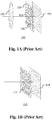
- 4D light-field data Compared to classical two-dimensional or 2D images obtained from a conventional camera, 4D light-field data enable a user to have access to more post-processing features that enhance the rendering of images and the interactivity with the user. For example, with 4D light-field data, it is possible to perform refocusing of images with freely selected distances of focalization meaning that the position of a focal plane can be specified/selected a posteriori, as well as changing slightly the point of view in the scene of an image. In order to acquire 4D light-field data, several techniques can be used. For example, a plenoptic camera is able to acquire 4D light-field data. Details of the architecture of a plenoptic camera are provided in Figure 1A.
- Figure 1A is a diagram schematically representing a plenoptic camera 100.
- the plenoptic camera 100 comprises a main lens 101, a microlens array 102 comprising a plurality of micro-lenses 103 arranged in a two-dimensional array and an image sensor 104.
- FIG. 1B represents a multi-array camera 110.
- the multi-array camera 110 comprises a lens array 112 and an image sensor 114.
- the main lens 101 receives light from an object (not shown on the figure) in an object field of the main lens 101 and passes the light through an image field of the main lens 101.
- Another way of acquiring a 4D light field is to use a conventional camera that is configured to capture a sequence of 2D images of a same scene at different focal planes.
- a conventional camera that is configured to capture a sequence of 2D images of a same scene at different focal planes.
- the technique described in the document " Light ray field capture using focal plane sweeping and its optical reconstruction using 3D displays" by J.-H. Park et al., published in OPTICS EXPRESS, Vol. 22, No. 21 , in October 2014 may be used to achieve the acquisition of 4D light field data by means of a conventional camera.
- 4D light-field data can be represented, when recorded by a plenoptic camera by a collection of micro-lens images. 4D light-field data in this representation are named raw images or raw 4D light-field data. Secondly, 4D light-field data can be represented, either when recorded by a plenoptic camera or by a camera array, by a set of sub-aperture images.
- a sub-aperture image corresponds to a captured image of a scene from a point of view, the point of view being slightly different between two sub-aperture images.
- These sub-aperture images give information about the parallax and depth of the imaged scene.
- 4D light-field data can be represented by a set of epipolar images see for example the article entitled : " Generating EPI Representation of a 4D Light Fields with a Single Lens Focused Plenoptic Camera", by S. Wanner and al., published in the conference proceedings of ISVC 2011 .
- Light-field data can take up large amounts of storage space, up to several Tera Bytes (TB), which can make storage cumbersome and processing less efficient.
- TB Tera Bytes
- Light-field acquisition devices are extremely heterogeneous.
- Light-field cameras are of different types, for example plenoptic or camera arrays. Within each type there are many differences such as different optical arrangements, or micro-lenses of different focal length sand, above all, each camera has its own proprietary file format. At present there is no standard supporting the acquisition and transmission of multi-dimensional information for an exhaustive over-view of the different parameters upon which a light-field depends. As such, acquired light-field data for different cameras have a diversity of formats.
- the present invention has been devised with the foregoing in mind.
- a pixel beam is defined as a pencil of rays of light that reaches a given pixel of a sensor of an optical acquisition system when propagating through the optical system of the optical acquisition system.
- a pixel beam is represented by a hyperboloid of one sheet.
- a hyperboloid of one sheet is a ruled surface that supports the notion of pencil of rays of light and is compatible with the notion of the "étendue" of physical light beams.
- Etendue is a property of light in an optical system which characterizes how “spread out” the light is in area and angle.
- the "étendue" is the product of the area of the source and ae solid angle that an optical system's entrance pupil subtends as seen from the source. Equivalently, from the optical system point of view, the "étendue" equals the area of the entrance pupil times the solid angle the source subtends as seen from the pupil.
- the "étendue” is related to the Lagrange invariant and the optical invariant, which share the property of being constant in an ideal optical system.
- the radiance of an optical system is equal to the derivative of the radiant flux with respect to the "étendue".
- 4D light-field data may be represented by a collection of pixel beams which can take up large amounts of storage space since pixel beams may be represented by six to ten parameters.
- a compact representation format for 4D light-field data developed by the inventors of the present invention relies on a ray-based representation of the plenoptic function. This compact representation format requires the rays to be sorted in a way that is not random. Indeed, since rays are mapped along lines, it is efficient, in terms of compactness, to store in sequence the parameters of a given line, i.e. the slope related and the intercept, along with the collection of rays belonging to said given line and then a next line and so on.
- Pixel beams may be represented by two rays, called generating rays, describing a surface of the hyperboloid representing the pixel beam.
- Generating rays may suffer strong deviations while passing through the microlenses of the optical acquisition system and thus hit the main lens of the optical acquisition system at larger aperture angles. Aberrations like distortion may thus disturb the collection of generating rays making the use of the compact representation format less efficient.
- the method according to an embodiment of the invention consists in sorting the pairs of generating rays defining the pixel beams of a collection of pixel beams in order to reduce the randomness in position and orientation in order to make the use of the compact representation format more efficient.
- the method according to an embodiment of the invention constrains the pairs of generating rays defining the pixels beams of a collection of pixel beams in such a way that one of the parameters representing a pixel beam becomes implicit enabling to reduce the dimensions of the data set representing said pixel beam by one dimension thus contributing to the compactness of the compact representation format.
- the reference straight line is parallel to an optical axis of a main lens of the optical acquisition system.
- the reference straight line is parallel to a central axis of a lens-array of the optical acquisition system.
- computing the first, respectively the second, rotation angle consists in:
- the second and the fourth generating rays are sorted, prior to the generation of the set of data representative of the pixel beam, so that the first and the second rotation angles are arranged in increasing order.
- Arranging the second and the fourth generating rays so that the rotation angles in increasing order makes easier the reconstruction of a pixel beam by a rendering device, such as a television set, a smartphone, a tablet, a personal computer, a laptop, etc. by constraining the direction of cross products vectors involved in the computation of the set of data representative of the pixel beam to be reconstructed.
- a rendering device such as a television set, a smartphone, a tablet, a personal computer, a laptop, etc. by constraining the direction of cross products vectors involved in the computation of the set of data representative of the pixel beam to be reconstructed.
- the computed distance between one of the second or the fourth generating ray and the revolution axis of the hyperboloid is the shortest distance between one of the second or the fourth generating ray and the revolution axis of the hyperboloid.
- the shortest distance between one the second or the fourth generating ray and the revolution axis of the hyperboloid corresponds to the waist of the pixel beam, i.e. the smallest section of the hyperboloid representing the pixel beam.
- Such an apparatus may be embedded in an optical acquisition system such as a plenoptic camera or any other device such as smartphones, laptop, personal computers, tablets, etc.
- an optical acquisition system such as a plenoptic camera or any other device such as smartphones, laptop, personal computers, tablets, etc.
- the processor is configured to compute the first, respectively the second, rotation angle by:
- adevice for rendering a light-field content comprising a processor configured to:
- Such a device capable of rendering a light field content may be a television set, a smartphone, a laptop, a personal computer, a tablet, etc.
- Such a light field imaging device is for example a plenoptic camera.
- ignal representative of a light-field content comprising a set of data representative of a volume in an object space of an optical acquisition system occupied by a set of rays of light that at least one pixel of a sensor of said optical acquisition system can sense through a pupil of said optical acquisition system, said volume being called a pixel beam, the set of data representative of the pixel beam comprising:
- elements of the invention may be computer implemented. Accordingly, such elements may take the form of an entirely hardware embodiment, an entirely software embodiment (including firmware, resident software, micro-code, etc.) or an embodiment combining software and hardware aspects that may all generally be referred to herein as a "circuit", "module” or “system'. Furthermore, such elements may take the form of a computer program product embodied in any tangible medium of expression having computer usable program code embodied in the medium.
- a tangible carrier medium may comprise a storage medium such as a floppy disk, a CD-ROM, a hard disk drive, a magnetic tape device or a solid state memory device and the like.
- a transient carrier medium may include a signal such as an electrical signal, an electronic signal, an optical signal, an acoustic signal, a magnetic signal or an electromagnetic signal, e.g. a microwave or RF signal.
- aspects of the present principles can be embodied as a system, method or computer readable medium. Accordingly, aspects of the present principles can take the form of an entirely hardware embodiment, an entirely software embodiment, (including firmware, resident software, micro-code, and so forth) or an embodiment combining software and hardware aspects that can all generally be referred to herein as a "circuit", "module”, or “system”. Furthermore, aspects of the present principles can take the form of a computer readable storage medium. Any combination of one or more computer readable storage medium(a) may be utilized.
- Embodiments of the invention provide formatting of light-field data for further processing applications such as format conversion, refocusing, viewpoint change and 3D image generation.
- Figure 2A is a block diagram of a light-field camera device in accordance with an embodiment of the invention.
- the light-field camera comprises an aperture/shutter 202, a main (objective) lens 201, a micro lens array 210 and a photosensor array 220 in accordance with the light-field camera of Figure 1A .
- the light-field camera includes a shutter release that is activated to capture a light-field image of a subject or scene. It will be appreciated that the functional features may also be applied to the light-field camera of Figure 1B .
- the photosensor array 220 provides light-field image data which is acquired by LF Data acquisition module 240 for generation of a light-field data format by light-field data formatting module 250 and/or for processing by light-field data processor 255.
- Light-field data may be stored, after acquisition and after processing, in memory 290 in a raw data format, as sub aperture images or focal stacks, or in a light-field data format in accordance with embodiments of the invention.
- the light-field data formatting module 150 and the light-field data processor 255 are disposed in or integrated into the light-field camera 200.
- the light-field data formatting module 250 and/or the light-field data processor 255 may be provided in a separate component external to the light-field capture camera.
- the separate component may be local or remote with respect to the light-field image capture device.
- any suitable wired or wireless protocol may be used for transmitting light-field image data to the formatting module 250 or light-field data processor 255; for example the light-field data processor may transfer captured light-field image data and/ or other data via the Internet, a cellular data network, a WiFi network, a Bluetooth® communication protocol, and/ or any other suitable means.
- the light-field data formatting module 250 is configured to generate data representative of the acquired light-field, in accordance with embodiments of the invention.
- the light-field data formatting module 250 may be implemented in software, hardware or a combination thereof.
- the light-field data processor 255 is configured to operate on raw light-field image data received directly from the LF data acquisition module 240 for example to generate focal stacks or a matrix of views in accordance with embodiments of the invention. Output data, such as, for example, still images, 2D video streams, and the like of the captured scene may be generated.
- the light-field data processor may be implemented in software, hardware or a combination thereof.
- the light-field camera 200 may also include a user interface 260 for enabling a user to provide user input to control operation of camera 100 by controller 270.
- Control of the camera may include one or more of control of optical parameters of the camera such as shutter speed, or in the case of an adjustable light-field camera, control of the relative distance between the microlens array and the photosensor, or the relative distance between the objective lens and the microlens array. In some embodiments the relative distances between optical elements of the light-field camera may be manually adjusted. Control of the camera may also include control of other light-field data acquisition parameters, light-field data formatting parameters or light-field processing parameters of the camera.
- the user interface 260 may comprise any suitable user input device(s) such as a touchscreen, buttons, keyboard, pointing device, and/ or the like. In this way, input received by the user interface can be used to control and/ or configure the LF data formatting module 250 for controlling the data formatting, the LF data processor 255 for controlling the processing of the acquired light-field data and controller 270 for controlling the light-field camera 200.
- the light-field camera includes a power source 280, such as one or more replaceable or rechargeable batteries.
- the light-field camera comprises memory 290 for storing captured light-field data and/or rendered final images or other data such as software for implementing methods of embodiments of the invention.
- the memory can include external and/or internal memory. In at least one embodiment, the memory can be provided at a separate device and/ or location from camera 200. In one embodiment, the memory includes a removable/swappable storage device such as a memory stick.
- the light-field camera may also include a display unit 265 (e.g., an LCD screen) for viewing scenes in front of the camera prior to capture and/or for viewing previously captured and/or rendered images.
- the screen 265 may also be used to display one or more menus or other information to the user.
- the light-field camera may further include one or more I/O interfaces 295, such as FireWire or Universal Serial Bus (USB) interfaces, or wired or wireless communication interfaces for data communication via the Internet, a cellular data network, a WiFi network, a Bluetooth® communication protocol, and/ or any other suitable means.
- I/O interfaces 295 such as FireWire or Universal Serial Bus (USB) interfaces, or wired or wireless communication interfaces for data communication via the Internet, a cellular data network, a WiFi network, a Bluetooth® communication protocol, and/ or any other suitable means.
- the I/O interface 295 may be used for transferring data, such as light-field representative data generated by LF data formatting module in accordance with embodiments of the invention and light-field data such as raw light-field data or data processed by LF data processor 255, to and from external devices such as computer systems or display units, for rendering applications.
- data such as light-field representative data generated by LF data formatting module in accordance with embodiments of the invention and light-field data such as raw light-field data or data processed by LF data processor 255, to and from external devices such as computer systems or display units, for rendering applications.
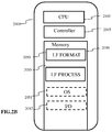
- Figure 2B is a block diagram illustrating a particular embodiment of a potential implementation of light-field data formatting module 250 and the light-field data processor 253.
- the circuit 2000 includes memory 2090, a memory controller 2045 and processing circuitry 2040 comprising one or more processing units (CPU(s)).
- the one or more processing units 2040 are configured to run various software programs and/or sets of instructions stored in the memory 2090 to perform various functions including light-field data formatting and light-field data processing.
- Software components stored in the memory include a data formatting module (or set of instructions) 2050 for generating data representative of acquired light data in accordance with embodiments of the invention and a light-field data processing module (or set of instructions) 2055 for processing light-field data in accordance with embodiments of the invention.
- Other modules may be included in the memory for applications of the light-field camera device such as an operating system module 2051 for controlling general system tasks (e.g. power management, memory management) and for facilitating communication between the various hardware and software components of the device 2000, and an interface module 2052 for controlling and managing communication with other devices via I/O interface ports.
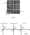
- FIG 3 illustrates an example of a 2D image formed on the photosensor array 220 of Figure 2A .
- the 2D image often referred to as a raw image representing 4D light-field, is composed of an array of micro images MI, each micro image being produced by the respective micro lens ( i,j ) of the microlens array 210.
- the micro images are arranged in the array in a rectangular lattice structure defined by axes i and j .
- a micro lens image may be referenced by the respective micro lens coordinates ( i , j ).
- a pixel PI of the photosensor 220 may be referenced by its spatial coordinates (x, y).
- 4D light-field data associated with a given pixel may be referenced as (x, y, i, j).
- a 4D light-field image can be represented, by a collection of micro-lens images as previously described with reference to Figure 3 .
- a 4D light-field image may also be represented, when recorded by a plenoptic camera by a set of sub-aperture images. Each sub-aperture image of composed of pixels of the same position selected from each microlens image.
- a 4D light-field image may be represented by a set of epipolar images, which is not the case of the pixel beam.
- Embodiments of the invention provide a representation of light-field data based on the notion of pixel beam.
- the diversity in formats and light-field devices may be taken into account.
- one drawback of ray based formats is that the parametrization planes, used to computes the parameters representing the rays, have to be sampled to reflect the pixel formats and sizes. Therefore, the sampling needs to be defined along other data in order to recover physical meaningful information.
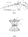
- a pixel beam 40 represents a volume occupied by a set of rays of light in an object space of an optical system 41 of a camera.
- the set of rays of light is sensed by a pixel 42 of a sensor 43 of the camera through a pupil 44 of said optical system 41.
- pixel beams 40 may be sample at will since they convey per se the "étendue" which corresponds to the preservation of the energy across sections of the physical light rays.
- a pupil of an optical system is defined as the image of an aperture stop as seen through part of said optical system, i.e. the lenses of the camera which precedes said aperture stop.
- An aperture stop is an opening which limits the amount of light which passes through the optical system of the camera.
- an adjustable diaphragm located inside a camera lens is the aperture stop for the lens.
- the amount of light admitted through the diaphragm is controlled by the diameter of the diaphragm opening which may adapted depending of the amount of light a user of the camera wishes to admit, or the depth of field the user wishes. For example, making the aperture smaller reduces the amount of light admitted through the diaphragm, but increases the depth of field.
- the apparent size of a stop may be larger or smaller than its physical size because of the refractive action of a lens.
- a pupil is the image of the aperture stop through the optical system of the camera.
- a pixel beam 40 is defined as a pencil of rays of light that reaches a given pixel 42 when propagating through the optical system 41 via an entrance pupil 44. As light travels on straight lines in free space, the shape of such a pixel beam 40 can be defined by two sections, one being the conjugate 45 of the pixel 42, and the other being the entrance pupil 44.
- the pixel 42 is defined by its non-null surface and its sensitivity map.
- a pixel beam may be represented by a hyperboloid of one sheet 50, as shown on figure 5 , supported by two elements: the pupil 54 and the conjugate 55 of the pixel 42 in the object space of the camera.
- a hyperboloid of one sheet is a ruled surface that can support the notion of pencil of rays of light and is compatible with the notion of "étendue" of physical light beams.
- a hyperboloid of one sheet is a ruled surface
- at least one family of straight lines, called generating rays, rotating around a revolution axis, called chief ray, of the hyperboloid describe such a surface.
- the knowledge of parameters defining the chief ray and any generating ray belonging to a family of generating lines of the hyperboloid are sufficient to define a pixel beam 40, 50.
- Figure 6A is a block diagram schematically illustrating the main modules of an apparatus for sorting the generating rays of a collection of pixel beams of a camera according to one or more embodiments of the invention.
- the apparatus 600 comprises a processor 601, a storage unit 602, an input device 603, a display device 604, and an interface unit 605 which are connected by a bus 606.
- a processor 601 a storage unit 602, an input device 603, a display device 604, and an interface unit 605 which are connected by a bus 606.
- constituent elements of the computer apparatus 600 may be connected by a connection other than a bus connection.
- the processor 601 controls operations of the apparatus 600.
- the storage unit 602 stores at least one program capable of sorting the generating rays of a collection of pixel beams of a camera to be executed by the processor 601, and various data, including parameters related to the optical system 210 of the optical acquisition system, parameters used by computations performed by the processor 601, intermediate data of computations performed by the processor 601, and so on.
- the processor 601 may be formed by any known and suitable hardware, or software, or a combination of hardware and software.
- the processor 601 may be formed by dedicated hardware such as a processing circuit, or by a programmable processing unit such as a CPU (Central Processing Unit) that executes a program stored in a memory thereof.
- CPU Central Processing Unit
- the storage unit 602 may be formed by any suitable storage or means capable of storing the program, data, or the like in a computer-readable manner. Examples of the storage unit 602 include non-transitory computer-readable storage media such as semiconductor memory devices, and magnetic, optical, or magneto-optical recording media loaded into a read and write unit.
- the program causes the processor 601 to perform a process for computing parameters representing a volume occupied by a set of rays of light in an object space of an optical system and encoding these parameters with an image captured by the optical acquisition system according to an embodiment of the present disclosure as described hereinafter with reference to figure 9B .
- the input device 603 may be formed by a keyboard, a pointing device such as a mouse, or the like for use by the user to input commands, to make user's selections of parameters used for generating a parametric representation of a volume occupied by a set of rays of light in an object space of an optical system.
- the output device 604 may be formed by a display device to display, for example, a Graphical User Interface (GUI), images generated according to an embodiment of the present disclosure.
- GUI Graphical User Interface
- the input device 603 and the output device 604 may be formed integrally by a touchscreen panel, for example.
- the interface unit 605 provides an interface between the apparatus 600 and an external apparatus.
- the interface unit 605 may be communicable with the external apparatus via cable or wireless communication.
- the external apparatus may be a camera, or a portable device embedding such a camera like a mobile phone, a tablet, etc.
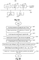
- Figure 6B is a flow chart illustrating the steps of a method for sorting the generating rays of a collection of pixel beams of a camera according to one or more embodiments of the invention.
- M ⁇ 1 M 1 ⁇ .
- the triplet ( x 1 , y 1 , k ) can define any generating ray ⁇ crossing ⁇ .
- the dimensionality is thus reduced from four to three.
- the triplet ( x 1 , y 1 , z I ⁇ 1 ) can define the generating ray ( M 1 , I ⁇ ), where, I ⁇ is the intersection point between the reference straight line ⁇ and the generating ray ⁇ , and z I ⁇ 1 the coordinate of I ⁇ along Oz.
- parameters ( x 0 , y 0 , z 0 ), a, b, c and ⁇ x , ⁇ y defining the different pixel beams associated to the pixels of the sensor of the camera are acquired either by calibrating the camera of by retrieving such parameters from a data file stored in a remote server or on a local storage unit such as the memory 290 of the camera or a flash disk connected to the camera.
- This acquisition or calibration may be executed by the processor 601 of the apparatus 600.
- the computation of the values of the parameters ( x 0 , y 0 , z 0 ) , a, b, c and ⁇ x , ⁇ y is realized, for example, by running a program capable of modelling a propagation of rays of light through the optical system of the camera.
- a program is for example an optical design program such as Zemax ⁇ , ASAP ⁇ or Code V ⁇ .
- An optical design program is used to design and analyze optical systems.
- An optical design program models the propagation of rays of light through the optical system; and can model the effect of optical elements such as simple lenses, aspheric lenses, gradient index lenses, mirrors, and diffractive optical elements, etc.
- the optical design program may be executed by the processor 601 of the apparatus 600.
- a step S602 executed by the processor 601 the shear of the chief ray of a pixel beam is removed.
- the central axis of the hyperboloid is the Oz axis
- two points belonging to this axis have the following set of coordinates (0,0,0) and (0,0,1) in the ( XYZ ) coordinate system.
- This central axis of the hyperboloid, transformed back in the original coordinate system (x, y, z), is the chief ray ⁇ C of the pixel beam.
- the hyperboloid defined by equation (4) has two families of generating rays:
- Any of these generating rays, transformed back in the original coordinate system, can be selected as ⁇ G 0 a generating ray of a pixel beam.
- the processor 601 applies the function T as defined above to a reference straight line ⁇ in the object space of the camera.
- the reference straight line ⁇ is an optical axis of a main lens of the camera.
- the reference straight line ⁇ is a central axis of a lens-array of the camera, in a third embodiment the reference straight line ⁇ is a line with a direction forming an angle inferior or equal to ⁇ 4 with the optical axis of the main lens of the camera.
- the reference straight line ⁇ is defined by two points of coordinates P ⁇ 0 ( x ⁇ 0 , y ⁇ 0 , z ⁇ 0 ) and P ⁇ 1 ( x ⁇ 1 , y ⁇ 1 , z ⁇ 1 ) in the ( x, y , z ) coordinates system.
- the processor 601 computes the value of two distinct rotation angles ⁇ a and ⁇ b enabling the computation of two image rays ⁇ G ⁇ a and ⁇ G ⁇ b of the generating ray ⁇ G 0 called transformed generating rays.
- the two image rays of the generating ray ⁇ G 0 i.e. rays ⁇ G ⁇ a and ⁇ G ⁇ b are obtained by, respectively, the rotation of angle ⁇ a and ⁇ b around the chief ray ⁇ C .
- a rotation angle ⁇ is obtained when a given generating ray ⁇ G ⁇ crosses the reference straight line ⁇ , i.e the distance between the reference straight line ⁇ and the generating ray ⁇ G ⁇ is equal to 0.
- tan 2 ⁇ C 2 1 + tan 2 ⁇ ⁇ B 2 ⁇ C 2 . tan 2 ⁇ + 2.
- a . B . tan ⁇ + A 2 ⁇ C 2 0
- Discriminant: ⁇ 4.
- a 2 ⁇ C 2 4.
- the two rays ⁇ G ⁇ a and ⁇ G ⁇ b are selected among four different rays generating the pixel beam.
- This method is run on the different pixel beams of the camera.
- two collections of rays are obtained: a first collection of rays comprising the first transformed generating rays ⁇ G ⁇ a of the pixel beams of the camera and a second collection of rays comprising the second transformed generating rays ⁇ G ⁇ b .
- a step S607 the transformed generated rays ⁇ G ⁇ a and ⁇ G ⁇ b are reordered if needed in the collection of generating rays so that: 0 ⁇ ⁇ b - ⁇ a ⁇ ⁇ .
- a step S608 the shortest distance d between one of the image rays ⁇ G ⁇ a or ⁇ G ⁇ b and the chief ray ⁇ C is computed.
- This shortest distance d corresponds to the waist the hyperboloid representing a pixel beam and is computed according to the method given by (Gellert et al. 1989, p. 538) as describe previously in reference to step S605 of the method according to an embodiment of the invention.
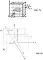
- a method for parametrizing the four dimensions of light-field radiance may be with reference to the cube illustrated in Figure 7A . All six faces of the cube may be used to parameterize the light-field. In order to parameterize direction, a second set of planes parallel to the cube faces, may be added. In this way the light-field may be defined with respect to six pairs of planes with normals along the axis directions as: i ⁇ , ⁇ i ⁇ , j ⁇ , ⁇ j ⁇ , k ⁇ , ⁇ k ⁇
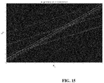
- Figure 7B illustrates a light-field ray, such as generating rays defining a pixel beam, passing through two reference planes P1 and P2 used for parameterization positioned parallel to one another and located at known depths z 1 and z 2 respectively.
- the light-field ray intersects the first reference plane P 1 at depth z 1 at intersection point ( x 1 , y 1 ) and intersects the second reference plane P 2 at depth z 2 at intersection point ( x 2 , y 2 ).
- the light-field ray may be identified by four coordinates ( x 1 , y 1 , x 2 , y 2 ).
- the light-field can thus be parameterized by a pair of reference planes for parameterization P 1 , P 2 also referred herein as parametrization planes, with each light-field ray being represented as a point ( x 1 ,y 1 ,x 2 ,x 2 ) ⁇ R 4 in 4D ray space.
- P 1 , P 2 also referred herein as parametrization planes
- each light-field ray being represented as a point ( x 1 ,y 1 ,x 2 ,x 2 ) ⁇ R 4 in 4D ray space.
- an origin of the reference co-ordinate system may be placed at the center of a plane P 1 generated by the basis vectors of the coordinate axis system ( i 1 , j 1 ).
- the entire light-field may be characterized by six pairs of such planes.
- a pair of planes, often referred to as a light slab characterizes the light-field interacting with the sensor or sensor array of the light-field camera along a direction of propagation.
- n the normal
- d an offset from the origin of the 3D coordinate system along the direction of the normal.
- x 1 ⁇ x i ⁇ + u ⁇ n ⁇ x 0 ⁇ ⁇ x i ⁇ u ⁇ n ⁇
- Both sets of equation should deliver the same point x 3 as the rendered light-field ray at the new location.
- Co-ordinates with a subscript 3 relate to a known point ( x 3 , y 3 , z 3 ) where the light-field is rendered. All depth co-ordinates z i are known.
- the parameterisation planes are in the direction of propagation or rendering.
- the light-field data parameters L are ( x 1 , y 1 , x 2 , y 2 )
- the light-field rays that form an image at point ( x 3 , y 3 , z 3 ) are linked by expression (B) which defines a hyper plane in .
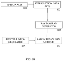
- Figure 9A is a flow chart illustrating the steps of a method for generating data representative of a light-field according to one or more embodiments of the invention.
- Figure 9B is a block diagram schematically illustrating the main modules of a system for generating data representative of a light-field according to one or more embodiments of the invention.
- a preliminary step S801 of the method parameters defining the the generating rays and the shortest distance d between one of the generating rays and the chief ray ⁇ C of the different pixel beams associated to the pixels of the sensor of the camera are acquired. These parameters are obtained as a result of the method for sorting the generating rays described above.
- Such parameters are the coordinates of two generating rays crossing the reference straight line of the different pixel
- raw light-field data is acquired by a light-field camera 801.
- the raw light-field data may for example be in the form of micro images as described with reference to Figure 3 .
- the light-field camera may be a light-field camera device such as shown in Figures 1A or 1B and 2A and 2B .
- step S803 the acquired light-field data is processed by ray parameter module 802 to provide intersection data ( x 1 , y 1 , x 2 , y 2 ) defining intersection of captured light-field rays, which correspond to the generating rays crossing the reference straight line of pixel beams 40, 50, with a pair of reference planes for parameterization P 1 , P 2 at respective depths z 1 , z 2 .
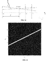
- the centre of projection ( x 3 , y 3 , z 3 ) the orientation of the optical axis of the camera and the distance f from the pinhole of the camera to the plane of the photosensor.
- the light-field camera parameters are illustrated in Figure 10 .
- the photosensor plane is located at depth z p .
- the pixel output of the photosensor is converted into geometrical representation of light-field rays.
- a light-slab comprising the two reference planes P 1 and P 2 is located at depths z 1 and z 2 , respectively, beyond z 3 , at the other side of the centre of projection of the camera to the photosensor.
- the above calculation may be extended to multiple cameras with different pairs of triplets ( x p , y p , z p ) ( x 3 , y 3 , z 3 ) :
- a camera model with an aperture is used and a light-field ray is described in the phase space as having an origin ( x p , y p , z p ) and a direction ( x' 3 , y' 3 , 1) .
- Its propagation unto the plane ( x 3 , y 3 ) at depth z 3 can be described as a matrix transform.
- the lens will act as an ABCD matrix to refract the ray and another ABCD propagation matrix will bring the ray onto the light-slab reference planes P 1 and P 2 .
- intersection data (x 1 , y 1 , x 2 , y 2 ) geometrically defining intersection of the generating ray crossing the reference straight line with reference planes P 1 , P 2 is obtained.
- step S804 2D ray a diagram graphically representing the intersection data (x 1 , y 1 , x 2 , y 2 ) is obtained by ray diagram generator module 803.
- the data lines of the ray diagram used to parameterise are sampled by 256 cells providing an image of 256x256 pixels.
- the ray diagram illustrated in Figure 11 is interpreted as a matrix, it can be seen that it is sparsely populated. If the rays were to be saved individually in a file instead of the 4D phase space matrix, this would require saving for each ray, at least 2 bytes (int16) for each position x i or x 3 plus 3 bytes for the color, i.e. 7 bytes per ray for a 2D slice light-field, and 11 bytes per ray for its full 4D representation. Even then, the rays would be stored randomly in the file which might be unsuitable for applications that need to manipulate the representation.
- the inventors of the present invention have determined how to extract only the representative data from the ray diagram matrix and to store the data in a file in a structured manner.
- the light-field rays are mapped along data lines of the 2D ray diagram, it is more efficient to store parameters defining the data line rather than the line values themselves.
- Parameters defining the data line such as, for example, a slope defining parameter s and an axis intercept d may be stored with the set of light-field rays belonging to that data line.
- the rays may be ordered along lines in the file. In order to set lines through matrix cells so called digital lines are generated which approximate the ray lines with minimum error.
- a Radon transform is performed by line detection module 804 on the ray diagram generated in step S804.
- a representative digital line is generated by digital line generation module 805 in step S806.
- digital lines are generated by approximating an analytical line to its nearest grid point, for example by applying Bresenham's algorithm.
- Bresenham's algorithm provides a way to provide a digital line with minimal operation.
- Other methods may apply a fast discrete Radon transform calculation.
- An example of Bresenham application is one adapted from the following reference:
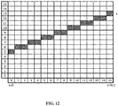
- Figure 12 illustrates an example of a digital line generated by application of Bresenham's algorithm.
- Figure 13 illustrates a group of digital lines having the same slope a (or s - d ) but different intercepts d, the group of data lines being contiguous.
- the group of data lines is referred to herein as a bundle of lines and corresponds to a beam resulting from the camera not being ideally a pinhole camera.
- Each line addresses different pixels. In other words, one pixel belongs only to a unique line of a bundle with the same slope but different intercepts.
- the upper and lower boundaries of the axis intersections d are given as d max and d min respectively.
- the header of the beam can simply contain the slope a and the thickness of the beam defined by the upper and lower boundaries of the axis intersections d max - d min .
- the ray values will be stored as RGB colors along digital lines whose header can be d and s. Void cells of the ray diagram in the sampled space do not need to be stored. Coordinates x1; x2 of the rays can be deduced from the parameters d, s and from the position of the cell along the digital line.
- Parameters to be estimated from the light-field or from camera's geometry are the slope a the lower and upper bounds of the digital line intercepts ( d min , d max ) ,and the digital line parameters ( d i , s i ) .
- the discrete Radon transform has already been discussed as a tool to measure the support location of the light-field in the ray diagram.
- Figure 14B shows the discrete Radon transform in the digital line parameter space ( d, s )of the datalines of Figure 14A.
- Figure 14C is a zoom of the region of interest comprised in Figure 14B .
- the beam of digital lines is located by the search for the maximum value parameters. There could be some offset between the geometrical center of symmetry of the DRT and the actual position of the maximum due to image content so that later on, an algorithm is used to pin-point the center of symmetry instead of the maximum. Then, the waist of the beam transform as shown on Figure 13C is easy to find to give the values ( d min , d max ) .
- the values of m and d max x , d min x , d max y , d min y may be evaluated in the discrete domain.
- DRT discrete Radon transform
- the sets of the equations may be solved for k, x 3 and y 3 .
- ( x 3 , y 3 , z 3 ) correspond to the coordinates of the camera, or in other words the voxel where the corresponding bundle of light is focused into a circle of the radius A.
- the digital lines may be scanned as before on ⁇ (x 1 ,x 2 ) using the Bresenham digital lines; For each individual (x 1 , x 2 ), value, the corresponding (y 1 , y 2 ) values captured in the light-field are stored. To find such values, expression C is exploited. All the following are either known or estimated from expressions F and G x3; y3; z3; z1; z2
- Table 1 An exemplary data format for a bundle of data lines per camera is illustrated in Table 1.
- the parameters ( m , k ) are found for all the peaks in the radon transform of ⁇ (x 1 , x 2 ), and put in one set. The same is done for the peaks in ( y 1 , y 2 ) and the parameters are put in another set.
- the maximum peak intensity is found in the 2D radon transform of ( x 1 , x 2 ) and the corresponding peak in ( y 1 , y 2 ) is found by matching the previously found parameters ( m , k ). After saving the data as mentioned in the last section, these peaks are cleaned from the radon transforms, and the next iteration is started, until nothing meaningful remains in the light-field
Landscapes
- Engineering & Computer Science (AREA)
- Physics & Mathematics (AREA)
- General Physics & Mathematics (AREA)
- Theoretical Computer Science (AREA)
- Computer Graphics (AREA)
- Architecture (AREA)
- Computer Hardware Design (AREA)
- General Engineering & Computer Science (AREA)
- Software Systems (AREA)
- Studio Devices (AREA)
- Image Processing (AREA)
- Automatic Focus Adjustment (AREA)
Priority Applications (7)
| Application Number | Priority Date | Filing Date | Title |
|---|---|---|---|
| EP15307174.1A EP3188123A1 (de) | 2015-12-30 | 2015-12-30 | Verfahren und vorrichtung zur erzeugung von daten, die einen pixelstrahl repräsentieren |
| PCT/EP2016/082853 WO2017114904A1 (en) | 2015-12-30 | 2016-12-29 | A method and an apparatus for generating data representative of a pixel beam |
| US16/067,260 US10762612B2 (en) | 2015-12-30 | 2016-12-29 | Method and an apparatus for generating data representative of a pixel beam |
| KR1020187018547A KR20180098564A (ko) | 2015-12-30 | 2016-12-29 | 픽셀 빔을 표현하는 데이터를 생성하는 방법 및 장치 |
| CN201680081243.XA CN108604372B (zh) | 2015-12-30 | 2016-12-29 | 用于生成表示像素束的数据的方法和装置 |
| EP16826362.2A EP3398161B1 (de) | 2015-12-30 | 2016-12-29 | Verfahren und vorrichtung zur erzeugung von daten, die einen pixelstrahl repräsentieren |
| JP2018534046A JP2019511851A (ja) | 2015-12-30 | 2016-12-29 | ピクセルビームを表すデータを生成する方法及び装置 |
Applications Claiming Priority (1)
| Application Number | Priority Date | Filing Date | Title |
|---|---|---|---|
| EP15307174.1A EP3188123A1 (de) | 2015-12-30 | 2015-12-30 | Verfahren und vorrichtung zur erzeugung von daten, die einen pixelstrahl repräsentieren |
Publications (1)
| Publication Number | Publication Date |
|---|---|
| EP3188123A1 true EP3188123A1 (de) | 2017-07-05 |
Family
ID=55221248
Family Applications (2)
| Application Number | Title | Priority Date | Filing Date |
|---|---|---|---|
| EP15307174.1A Withdrawn EP3188123A1 (de) | 2015-12-30 | 2015-12-30 | Verfahren und vorrichtung zur erzeugung von daten, die einen pixelstrahl repräsentieren |
| EP16826362.2A Active EP3398161B1 (de) | 2015-12-30 | 2016-12-29 | Verfahren und vorrichtung zur erzeugung von daten, die einen pixelstrahl repräsentieren |
Family Applications After (1)
| Application Number | Title | Priority Date | Filing Date |
|---|---|---|---|
| EP16826362.2A Active EP3398161B1 (de) | 2015-12-30 | 2016-12-29 | Verfahren und vorrichtung zur erzeugung von daten, die einen pixelstrahl repräsentieren |
Country Status (6)
| Country | Link |
|---|---|
| US (1) | US10762612B2 (de) |
| EP (2) | EP3188123A1 (de) |
| JP (1) | JP2019511851A (de) |
| KR (1) | KR20180098564A (de) |
| CN (1) | CN108604372B (de) |
| WO (1) | WO2017114904A1 (de) |
Cited By (2)
| Publication number | Priority date | Publication date | Assignee | Title |
|---|---|---|---|---|
| WO2019236347A1 (en) * | 2018-06-05 | 2019-12-12 | Interdigital Vc Holdings, Inc. | Prediction for light-field coding and decoding |
| WO2021028836A1 (en) * | 2019-08-12 | 2021-02-18 | Molecular Devices (Austria) GmbH | Sample imaging via two-pass light-field reconstruction |
Families Citing this family (3)
| Publication number | Priority date | Publication date | Assignee | Title |
|---|---|---|---|---|
| JP2018537877A (ja) * | 2015-09-17 | 2018-12-20 | トムソン ライセンシングThomson Licensing | ライトフィールドコンテンツをエンコードする方法 |
| KR20200067020A (ko) * | 2018-12-03 | 2020-06-11 | 삼성전자주식회사 | 캘리브레이션 방법 및 장치 |
| CN112307848B (zh) * | 2019-08-01 | 2024-04-30 | 惠普发展公司,有限责任合伙企业 | 检测视频会议中的欺骗说话者 |
Citations (1)
| Publication number | Priority date | Publication date | Assignee | Title |
|---|---|---|---|---|
| US20150177062A1 (en) * | 2013-12-19 | 2015-06-25 | Canon Kabushiki Kaisha | Information processing apparatus, information processing method, and storage medium |
Family Cites Families (9)
| Publication number | Priority date | Publication date | Assignee | Title |
|---|---|---|---|---|
| CH682698A5 (de) * | 1990-11-01 | 1993-10-29 | Fisba Optik Ag Bystronic Laser | Verfahren, bei dem mehrere, in einer oder mehreren Reihen angeordnete Strahlungsquellen abgebildet werden und Vorrichtung hierzu. |
| US6222679B1 (en) | 1999-08-31 | 2001-04-24 | Agilent Technologies | Mechanically simplified, high resolution, optical focusing and steering apparatus |
| CA2429880C (en) * | 2003-05-27 | 2009-07-07 | York University | Collaborative pointing devices |
| EP2110776B1 (de) * | 2005-12-23 | 2012-10-31 | Ingenia Holdings Limited | Optische Authentifizierung |
| EP2839663A1 (de) * | 2012-04-19 | 2015-02-25 | Thomson Licensing | Verfahren und vorrichtung zur korrektur von verzerrungsfehlern aufgrund der akkommodationswirkung in stereoskopischer anzeige |
| CN104303493A (zh) * | 2012-05-09 | 2015-01-21 | 莱特洛公司 | 用于改进的光场捕获和操作的光学系统的优化 |
| KR20160106045A (ko) * | 2013-11-22 | 2016-09-09 | 비디노티 에스아 | 광필드 처리방법 |
| EP3144887A1 (de) * | 2015-09-17 | 2017-03-22 | Thomson Licensing | Verfahren und vorrichtung zur erzeugung von daten, die einen pixelstrahl repräsentieren |
| EP3188124A1 (de) * | 2015-12-30 | 2017-07-05 | Thomson Licensing | Verfahren und vorrichtung zur erzeugung von daten, die einen pixelstrahl repräsentieren |
-
2015
- 2015-12-30 EP EP15307174.1A patent/EP3188123A1/de not_active Withdrawn
-
2016
- 2016-12-29 CN CN201680081243.XA patent/CN108604372B/zh active Active
- 2016-12-29 US US16/067,260 patent/US10762612B2/en active Active
- 2016-12-29 JP JP2018534046A patent/JP2019511851A/ja not_active Ceased
- 2016-12-29 EP EP16826362.2A patent/EP3398161B1/de active Active
- 2016-12-29 WO PCT/EP2016/082853 patent/WO2017114904A1/en unknown
- 2016-12-29 KR KR1020187018547A patent/KR20180098564A/ko unknown
Patent Citations (1)
| Publication number | Priority date | Publication date | Assignee | Title |
|---|---|---|---|---|
| US20150177062A1 (en) * | 2013-12-19 | 2015-06-25 | Canon Kabushiki Kaisha | Information processing apparatus, information processing method, and storage medium |
Non-Patent Citations (5)
| Title |
|---|
| ANAT LEVIN: "Understanding camera trade-offs through a Bayesian analysis of Iwhtf field projections", CONFERENCE PROCEEDINGS OF ECCV, 2008 |
| J.-H. PARK ET AL.: "Light ray field capture using focal plane sweeping and its optical reconstruction using 3D displays", OPTICS EXPRESS, vol. 22, no. 21, October 2014 (2014-10-01), XP055258585, DOI: doi:10.1364/OE.22.025444 |
| REN NG: "Digital Light Field Photography", July 2006 |
| S. WANNER: "Generating EPI Representation of a 4D Light Fields with a Single Lens Focused Pleno tic Camera", CONFERENCE PROCEEDINGS OF ISVC, 2011 |
| TODOR GEORGIEV ET AL: "Lytro camera technology: theory, algorithms, performance analysis", PROCEEDINGS OF SPIE, vol. 8667, 26 February 2013 (2013-02-26), pages 86671J, XP055203972, ISSN: 0277-786X, DOI: 10.1117/12.2013581 * |
Cited By (4)
| Publication number | Priority date | Publication date | Assignee | Title |
|---|---|---|---|---|
| WO2019236347A1 (en) * | 2018-06-05 | 2019-12-12 | Interdigital Vc Holdings, Inc. | Prediction for light-field coding and decoding |
| EP3804333A1 (de) * | 2018-06-05 | 2021-04-14 | InterDigital VC Holdings, Inc. | Vorhersage für die lichtfeldcodierung und -decodierung |
| US11570471B2 (en) | 2018-06-05 | 2023-01-31 | Interdigital Vc Holdings, Inc. | Prediction for light-field coding and decoding |
| WO2021028836A1 (en) * | 2019-08-12 | 2021-02-18 | Molecular Devices (Austria) GmbH | Sample imaging via two-pass light-field reconstruction |
Also Published As
| Publication number | Publication date |
|---|---|
| WO2017114904A1 (en) | 2017-07-06 |
| JP2019511851A (ja) | 2019-04-25 |
| CN108604372B (zh) | 2022-04-05 |
| EP3398161B1 (de) | 2022-02-02 |
| CN108604372A (zh) | 2018-09-28 |
| EP3398161A1 (de) | 2018-11-07 |
| US20190295232A1 (en) | 2019-09-26 |
| KR20180098564A (ko) | 2018-09-04 |
| US10762612B2 (en) | 2020-09-01 |
Similar Documents
| Publication | Publication Date | Title |
|---|---|---|
| EP3144880B1 (de) | Verfahren und vorrichtung zur erzeugung von lichtfeldrepräsentativen daten | |
| EP3398161B1 (de) | Verfahren und vorrichtung zur erzeugung von daten, die einen pixelstrahl repräsentieren | |
| EP3144887A1 (de) | Verfahren und vorrichtung zur erzeugung von daten, die einen pixelstrahl repräsentieren | |
| EP3350770B1 (de) | Vorrichtung und verfahren zur erzeugung von daten, die einen pixelstrahl repräsentieren | |
| US20190101765A1 (en) | A method and an apparatus for generating data representative of a pixel beam | |
| EP3145168A1 (de) | Vorrichtung und verfahren zur erzeugung von daten, die einen pixelstrahl repräsentieren | |
| EP3479571B1 (de) | Vorrichtung und verfahren zur erzeugung von daten, die einen pixelstrahl repräsentieren |
Legal Events
| Date | Code | Title | Description |
|---|---|---|---|
| PUAI | Public reference made under article 153(3) epc to a published international application that has entered the european phase |
Free format text: ORIGINAL CODE: 0009012 |
|
| AK | Designated contracting states |
Kind code of ref document: A1 Designated state(s): AL AT BE BG CH CY CZ DE DK EE ES FI FR GB GR HR HU IE IS IT LI LT LU LV MC MK MT NL NO PL PT RO RS SE SI SK SM TR |
|
| AX | Request for extension of the european patent |
Extension state: BA ME |
|
| STAA | Information on the status of an ep patent application or granted ep patent |
Free format text: STATUS: THE APPLICATION IS DEEMED TO BE WITHDRAWN |
|
| 18D | Application deemed to be withdrawn |
Effective date: 20180106 |