EP3187940A1 - Detection gear and developing cartridge - Google Patents
Detection gear and developing cartridge Download PDFInfo
- Publication number
- EP3187940A1 EP3187940A1 EP15899116.6A EP15899116A EP3187940A1 EP 3187940 A1 EP3187940 A1 EP 3187940A1 EP 15899116 A EP15899116 A EP 15899116A EP 3187940 A1 EP3187940 A1 EP 3187940A1
- Authority
- EP
- European Patent Office
- Prior art keywords
- gear
- developing cartridge
- engaging portion
- cartridge according
- diameter
- Prior art date
- Legal status (The legal status is an assumption and is not a legal conclusion. Google has not performed a legal analysis and makes no representation as to the accuracy of the status listed.)
- Withdrawn
Links
Images









Classifications
-
- G—PHYSICS
- G03—PHOTOGRAPHY; CINEMATOGRAPHY; ANALOGOUS TECHNIQUES USING WAVES OTHER THAN OPTICAL WAVES; ELECTROGRAPHY; HOLOGRAPHY
- G03G—ELECTROGRAPHY; ELECTROPHOTOGRAPHY; MAGNETOGRAPHY
- G03G15/00—Apparatus for electrographic processes using a charge pattern
- G03G15/06—Apparatus for electrographic processes using a charge pattern for developing
- G03G15/08—Apparatus for electrographic processes using a charge pattern for developing using a solid developer, e.g. powder developer
- G03G15/0822—Arrangements for preparing, mixing, supplying or dispensing developer
- G03G15/0865—Arrangements for supplying new developer
-
- G—PHYSICS
- G03—PHOTOGRAPHY; CINEMATOGRAPHY; ANALOGOUS TECHNIQUES USING WAVES OTHER THAN OPTICAL WAVES; ELECTROGRAPHY; HOLOGRAPHY
- G03G—ELECTROGRAPHY; ELECTROPHOTOGRAPHY; MAGNETOGRAPHY
- G03G15/00—Apparatus for electrographic processes using a charge pattern
- G03G15/06—Apparatus for electrographic processes using a charge pattern for developing
- G03G15/08—Apparatus for electrographic processes using a charge pattern for developing using a solid developer, e.g. powder developer
- G03G15/0822—Arrangements for preparing, mixing, supplying or dispensing developer
- G03G15/0863—Arrangements for preparing, mixing, supplying or dispensing developer provided with identifying means or means for storing process- or use parameters, e.g. an electronic memory
-
- G—PHYSICS
- G03—PHOTOGRAPHY; CINEMATOGRAPHY; ANALOGOUS TECHNIQUES USING WAVES OTHER THAN OPTICAL WAVES; ELECTROGRAPHY; HOLOGRAPHY
- G03G—ELECTROGRAPHY; ELECTROPHOTOGRAPHY; MAGNETOGRAPHY
- G03G15/00—Apparatus for electrographic processes using a charge pattern
- G03G15/06—Apparatus for electrographic processes using a charge pattern for developing
- G03G15/08—Apparatus for electrographic processes using a charge pattern for developing using a solid developer, e.g. powder developer
- G03G15/0896—Arrangements or disposition of the complete developer unit or parts thereof not provided for by groups G03G15/08 - G03G15/0894
-
- G—PHYSICS
- G03—PHOTOGRAPHY; CINEMATOGRAPHY; ANALOGOUS TECHNIQUES USING WAVES OTHER THAN OPTICAL WAVES; ELECTROGRAPHY; HOLOGRAPHY
- G03G—ELECTROGRAPHY; ELECTROPHOTOGRAPHY; MAGNETOGRAPHY
- G03G21/00—Arrangements not provided for by groups G03G13/00 - G03G19/00, e.g. cleaning, elimination of residual charge
- G03G21/16—Mechanical means for facilitating the maintenance of the apparatus, e.g. modular arrangements
- G03G21/1642—Mechanical means for facilitating the maintenance of the apparatus, e.g. modular arrangements for connecting the different parts of the apparatus
- G03G21/1647—Mechanical connection means
-
- G—PHYSICS
- G03—PHOTOGRAPHY; CINEMATOGRAPHY; ANALOGOUS TECHNIQUES USING WAVES OTHER THAN OPTICAL WAVES; ELECTROGRAPHY; HOLOGRAPHY
- G03G—ELECTROGRAPHY; ELECTROPHOTOGRAPHY; MAGNETOGRAPHY
- G03G2221/00—Processes not provided for by group G03G2215/00, e.g. cleaning or residual charge elimination
- G03G2221/16—Mechanical means for facilitating the maintenance of the apparatus, e.g. modular arrangements and complete machine concepts
- G03G2221/1651—Mechanical means for facilitating the maintenance of the apparatus, e.g. modular arrangements and complete machine concepts for connecting the different parts
- G03G2221/1657—Mechanical means for facilitating the maintenance of the apparatus, e.g. modular arrangements and complete machine concepts for connecting the different parts transmitting mechanical drive power
Definitions
- the present invention relates to a detection gear or a developing cartridge.
- a developing cartridge known in the art is provided with a detection gear including a protrusion (refer to Patent Literature 1, for example).
- a detection gear including a protrusion (refer to Patent Literature 1, for example).
- an image forming apparatus provided with an actuator (refer to Patent Literature 1, for example).
- the detection gear rotates.
- the rotation of the detection gear shifts the protrusion between a contact state in which the protrusion is in contact with the actuator, and a non-contact state in which the protrusion is not in contact with the actuator.
- Patent Literature 1 Japanese Patent No. 4348632
- the inventors of the present invention have devised a new detection gear.
- a developing cartridge may include a casing that can accommodate developer therein. Further, the developing cartridge may include a first gear rotatable about a first axis extending in an axial direction. Further, the first gear may include a small-diameter gear portion. Further, the first gear may include a large-diameter gear portion having a diameter greater than a diameter of the small-diameter gear portion. Further, the developing cartridge may include a second gear rotatable about a second axis extending in the axial direction. Further, the second gear may include a first columnar portion that extends in the axial direction and is centered on the second axis.
- the second gear may include a second columnar portion that extends in the axial direction and is centered on the second axis and that has a diameter smaller than a diameter of the first columnar portion.
- the second gear may include a first engaging portion that is provided along a portion of a circumferential surface of the first columnar portion and that is engageable with the small-diameter gear portion.
- the second gear may include a second engaging portion that is provided along a portion of a circumferential surface of the second columnar portion and that is positioned closer to the casing in the axial direction than the first engaging portion to the casing in the axial direction and that is engageable with the large-diameter gear portion.
- the second gear may include a protrusion that protrudes in the axial direction and that is rotatable together with the first engaging portion and the second engaging portion.
- the second engaging portion may be capable of engaging with the large-diameter gear portion after the first engaging portion is engaged with the small-diameter gear portion.
- first engaging portion may include a plurality of gear teeth provided on a portion of the circumferential surface of the first columnar portion.
- second engaging portion may include a plurality of gear teeth provided on a portion of the circumferential surface of the second columnar portion.
- the plurality of gear teeth of the first engaging portion of the developing cartridge may be capable of meshing with the small-diameter gear portion.
- the plurality of gear teeth of the second engaging portion may be capable of meshing with the large-diameter gear portion.
- the first engaging portion may include a friction member provided along a portion of a circumference of the first columnar portion.
- the friction member may be a rubber.
- the second engaging portion may also include a friction member provided along a portion of a circumference of the second columnar portion.
- the friction member may be a rubber.
- the developing cartridge may further include an agitator that can agitate developer accommodated in the casing. Further, the first gear may be supported by a shaft of the agitator.
- small-diameter gear portion and the large-diameter gear portion may be rotatable about the first axis.
- the second gear may include a flange that is positioned separated farther from the casing than the first engaging portion from the casing and that is rotatable about the second axis.
- the protrusion may protrude from a surface of the flange opposite to a surface of the flange facing the casing.
- first columnar portion may have a cylindrical shape that extends in the axial direction.
- a distance in the axial direction between an outer surface of the casing and the large-diameter gear portion may be smaller than a distance in the axial direction between an outer surface of the casing and the small-diameter gear portion.
- the second columnar portion of the second gear may be rotatably supported by a boss that is positioned at an outer surface of the casing and that extends in the axial direction.
- boss may be a separate member from the casing.
- the casing may have a fill hole for filling the casing with developer. Further, the casing may have a cap for closing the fill hole. Further, the cap may include the boss.
- the boss may protrude from the outer surface of the casing.
- the developing cartridge may include a spring that is configured to be in contact with the second gear to urge the second gear in a rotating direction of the second gear after the first engaging portion is engaged with the small-diameter gear portion and until the second engaging portion becomes engaged with the large-diameter gear portion.
- the spring may be in contact with the second gear at a position between the first engaging portion and the second engaging portion in the axial direction.
- the spring may be a torsion coil spring.
- the casing may have a fill hole through which developer is accommodated in the casing. Further, the casing may have a cap for closing the fill hole. Further, one end of the spring may be in contact with the cap while the other end of the spring may be in contact with the second gear.
- the spring may have a first arm that includes the one end, and a second arm that includes the other end. Further, the first arm and the second arm may extend so as to cross each other.
- the protrusion of the second gear may have an arcuate shape that extends in the rotating direction. Further, the protrusion may have a first end portion at one end in the rotating direction, and a second end portion at the opposite end from the first end portion in the rotating direction. Further, the protrusion may have an extension portion that extends from the second end portion toward the second axis.
- extension portion may be curved.
- extension portion may be connected to the second columnar portion.
- an angle between a line segment connecting the first end portion and the second axis and a line segment connecting the second end portion and the second axis may be not smaller than 188° and not greater than 190°.
- an angle between a line segment connecting the first end portion and the second axis and a line segment connecting the second end portion and the second axis may be not smaller than 97° and not greater than 99°.
- first gear may include a first rib that extends in a radial direction of the first gear and that is rotatable together with the first gear.
- second gear may include a second rib that extends in a radial direction of the second gear and that is rotatable together with the second gear.
- the second gear may move from a first position in which the first engaging portion is positioned outside a locus of the small-diameter gear portion to a second position in which the first engaging portion is engaged with the small-diameter gear portion after the first rib becomes engaged with the second rib in accordance with rotation of the first gear.
- the second gear may move from the second position to a third position in which the second engaging portion is engaged with the large-diameter gear portion. Further, the second gear may move from the third position to a fourth position in which the second engaging portion is positioned outside a locus of the large-diameter gear portion.
- the second gear may include a third rib that protrudes outward from a circumferential surface in the radial direction of the second gear. Further, the spring may urge the third rib in a direction opposite to the rotating direction while the second gear is at the first position.
- the casing may have a restricting portion that extends in the axial direction and that is configured to be in contact with the second gear and restrict movement of the second gear in the direction opposite to the rotating direction while the third rib is urged by the spring.
- the third rib may be provided at a circumferential surface of the second columnar portion.
- the second gear may include a fourth rib that protrudes outward in the radial direction of the second gear from a circumferential surface. Further, the spring may urge the fourth rib in the rotating direction while the second gear is at a prescribed position between the second position and the third position.
- the fourth rib may be provided at the circumferential surface of the second columnar portion.
- third rib and the fourth rib may be positioned between the first engaging portion and the second engaging portion in the axial direction.
- the second rib may be provided at the circumferential surface of the second columnar portion.
- the protrusion may include a first portion that is configured to be in contact with a portion of an image forming apparatus when the second gear is at the first position. Further, the protrusion may include a second portion that is configured to be in contact with a portion of the image forming apparatus when the second gear is at the fourth position.
- first engaging portion may include a third end portion at one end in the rotating direction and a fourth end portion at the opposite end from the third end portion in the rotating direction.
- second engaging portion may include a fifth end portion at one end in the rotating direction and a sixth end portion at the opposite end from the fifth end portion in the rotating direction.
- the fifth end portion may be positioned closer to the fourth end portion in the rotating direction than the sixth end portion to the fourth end portion in the rotating direction.
- an angle between a line segment connecting the fourth end portion and the second axis and a line segment connecting the fifth end portion and the second axis may be not smaller than 35° and not greater than 41°.
- an angle between the line segment connecting the fifth end portion and the second axis and a line segment connecting the sixth end portion and the second axis may be not smaller than 28° and not greater than 32°.
- an angle between a line segment connecting the third end portion and the second axis and the line segment connecting the fourth end portion and the second axis may be not smaller than 146° and not greater than 150°.
- an angle between a line segment connecting the third end portion and the second axis and the line segment connecting the fourth end portion and the second axis may be not smaller than 73° and not greater than 78°.
- the developing cartridge may include a developing roller that extends in the axial direction.
- a developing cartridge may include a casing that can accommodate developer therein.
- the developing cartridge may include a first gear that is rotatable about a first axis extending in an axial direction. Further, the first gear may include a small-diameter gear portion. Further, the first gear may include a large-diameter gear portion having a diameter greater than a diameter of the small-diameter gear portion.
- the developing cartridge may include a second gear that is rotatable about a second axis extending in the axial direction.
- the second gear may include a first engaging portion that is provided along a portion of a circumferential surface of the second gear and that is engageable with the small-diameter gear portion.
- the second gear may include a second engaging portion that is provided at a position closer to the casing in the axial direction than the first engaging portion to the casing in the axial direction and that is provided along a portion of a circumferential surface of the second gear, the second engaging portion being provided at a position different from the first engaging portion in a rotating direction of the second gear and being engageable with the large-diameter gear portion after the first engaging portion is engaged with the small-diameter gear portion.
- the second gear may include a protrusion that protrudes in the axial direction and that is rotatable together with the first engaging portion and the second engaging portion. Further, a locus defined by rotation of the second engaging portion may be smaller than a locus defined by rotation of the first engaging portion.
- first engaging portion may include a plurality of gear teeth provided on the portion of the circumferential surface of the second gear.
- second engaging portion may include a plurality of gear teeth provided on the portion of the circumferential surface of the second gear.
- the plurality of gear teeth of the first engaging portion may be capable of engaging with the small-diameter gear portion.
- the plurality of gear teeth of the second engaging portion may be capable of engaging with the large-diameter gear portion.
- the first engaging portion may include a friction member that is engageable with the small-diameter gear portion through friction.
- the friction member may be a rubber.
- the second engaging portion may include a friction member that is engageable with the large-diameter gear portion through friction.
- the friction member may be a rubber.
- the developing cartridge may further include an agitator that can agitate developer accommodated in the casing. Further, the first gear may be supported by a shaft of the agitator.
- small-diameter gear portion and the large-diameter gear portion may be rotatable about the first axis.
- the second gear may include a flange that is positioned separated farther from the casing than the first engaging portion from the casing and that is rotatable about the second axis.
- the protrusion may protrude from a surface of the flange opposite to a surface of the flange facing the casing.
- the second gear may include a cylindrically shaped first columnar portion that extends in the axial direction and is centered on the second axis. Further, the first engaging portion may extend along a portion of a circumferential surface of the first columnar portion.
- a distance in the axial direction between an outer surface of the casing and the large-diameter gear portion may be smaller than a distance in the axial direction between the outer surface of the casing and the small-diameter gear portion.
- the second gear may include a second columnar portion that extends in the axial direction and is centered on the second axis, the second columnar portion having a diameter smaller than a dimeter of the first columnar portion.
- the second columnar portion may be rotatably supported by a boss that is positioned at an outer surface of the casing and extends in the axial direction.
- boss may be a separate member from the casing.
- the casing may have a fill hole for filling the casing with developer. Further, the casing may have a cap for closing the fill hole. Further, the cap may include the boss.
- the boss may protrude from the outer surface of the casing.
- the developing cartridge may include a spring that is configured to be in contact with the second gear to urge the second gear in a rotating direction of the second gear after the first engaging portion is engaged with the small-diameter gear portion and until the second engaging portion becomes engaged with the large-diameter gear portion.
- the spring may be in contact with the second gear at a position between the first engaging portion and the second engaging portion in the axial direction.
- the spring may be a torsion coil spring.
- the casing may have a fill hole through which developer is accommodated in the casing. Further, the casing may have a cap for closing the fill hole. Further, one end of the spring may be in contact with the cap while the other end of the spring may be in contact with the second gear.
- the spring may have a first arm that includes the one end, and a second arm that includes the other end. Further, the first arm and the second arm may extend so as to cross each other.
- the protrusion of the second gear may have an arcuate shape that extends in the rotating direction. Further, the protrusion may have a first end portion at one end in the rotating direction, and a second end portion at the opposite end from the first end portion in the rotating direction. Further, the protrusion may have an extension portion that extends from the second end portion toward the second axis.
- extension portion may be curved.
- extension portion may be connected to the second columnar portion.
- an angle between a line segment connecting the first end portion and the second axis and a line segment connecting the second end portion and the second axis may be not smaller than 188° and not greater than 190°.
- an angle between a line segment connecting the first end portion and the second axis and a line segment connecting the second end portion and the second axis may be not smaller than 97° and not greater than 99°.
- the first gear may include a first rib that extends in a radial direction of the first gear and that is rotatable together with the first gear.
- the second gear may include a second rib that extends in a radial direction of the second gear and that is rotatable together with the second gear. Further, in a state where the second rib is positioned on a locus of the first rib, the second gear may move from a first position in which the first engaging portion is positioned outside a locus of the small-diameter gear portion to a second position in which the first engaging portion is engaged with the small-diameter gear portion after the first rib becomes engaged with the second rib in accordance with rotation of the first gear.
- the second gear may move from the second position to a third position in which the second engaging portion is engaged with the large-diameter gear portion. Further, the second gear may move from the third position to a fourth position in which the second engaging portion is positioned outside a locus of the large-diameter gear portion.
- the second gear may include a third rib that protrudes outward from a circumferential surface in the radial direction of the second gear. Further, the spring may urge the third rib in a direction opposite to the rotating direction while the second gear is at the first position.
- the casing may have a restricting portion that extends in the axial direction and that is configured to be in contact with the second gear and restrict movement of the second gear in the direction opposite to the rotating direction while the third rib is urged by the spring.
- the third rib may be provided at a circumferential surface of the second columnar portion.
- the second gear may include a fourth rib that protrudes outward in the radial direction of the second gear from a circumferential surface. Further, the spring may urge the fourth rib in the rotating direction while the second gear is at a prescribed position between the second position and the third position.
- the fourth rib may be provided at a circumferential surface of the second columnar portion.
- third rib and the fourth rib may be positioned between the first engaging portion and the second engaging portion in the axial direction.
- the second rib may also be provided at a circumferential surface of the second columnar portion.
- the protrusion may include a first portion that is configured to be in contact with a portion of an image forming apparatus when the second gear is at the first position. Further, the protrusion may include a second portion that is configured to be in contact with a portion of the image forming apparatus when the second gear is at the fourth position.
- first engaging portion may include a third end portion at one end in the rotating direction and a fourth end portion at the opposite end from the third end portion in the rotating direction.
- second engaging portion may include a fifth end portion at one end in the rotating direction and a sixth end portion at the opposite end from the fifth end portion in the rotating direction.
- the fifth end portion may be positioned closer to the fourth end portion in the rotating direction than the sixth end portion to the fourth end portion in the rotating direction.
- an angle between a line segment connecting the fourth end portion and the second axis and a line segment connecting the fifth end portion and the second axis may be not smaller than 35° and not greater than 41°.
- an angle between the line segment connecting the fifth end portion and the second axis and a line segment connecting the sixth end portion and the second axis may be not smaller than 28° and not greater than 32°.
- an angle between a line segment connecting the third end portion and the second axis and the line segment connecting the fourth end portion and the second axis may be not smaller than 146° and not greater than 150°.
- an angle between a line segment connecting the third end portion and the second axis and the line segment connecting the fourth end portion and the second axis may be not smaller than 73° and not greater than 78°.
- the developing cartridge may include a developing roller that extends in the axial direction.
- a detection gear that is rotatable about an axis extending in an axial direction may include a protrusion that extends in the axial direction and that has an outer surface extending along a portion of a circumference of the detection gear. Further, the detection gear may include a first engaging portion that extends along a first portion of a circumference of the detection gear and that is positioned closer to the axis in a radial direction of the detection gear than the outer surface to the axis in the radial direction of the detection gear.
- the detection gear may include a second engaging portion that extends along a second portion of a circumference of the detection gear different from the first portion and that is positioned closer to the axis in the radial direction than the first engaging portion to the axis in the radial direction.
- the second engaging portion may be positioned at an opposite side of the outer surface with respect to the first engaging portion in the axial direction.
- the detection gear may further include a first cylindrical portion having a first diameter. Further, the detection gear may include a second cylindrical portion having a second diameter smaller than the first diameter.
- the first engaging portion may extend along a portion of a circumferential surface of the first cylindrical portion in a rotating direction of the detection gear.
- the second engaging portion may extend along a portion of a circumferential surface of the second cylindrical portion in the rotating direction.
- the second cylindrical portion may be positioned at an opposite side of the outer surface with respect to the first cylindrical portion.
- the protrusion may protrude in the axial direction from the first cylindrical portion.
- a length of the first engaging portion in the rotating direction may be greater than a length of the second engaging portion in the rotating direction.
- the second engaging portion may be spaced apart from the first engaging portion in the rotating direction.
- first engaging portion may include a first end portion at one end in the rotating direction, and a second end portion separated from the first end portion in the rotating direction. Further, the second end portion may be positioned closer to the second engaging portion in the rotating direction than the first end portion to the second engaging portion in the rotating direction. Further, the second engaging portion may include a third end portion at one end in the rotating direction, and a fourth end portion separated from the third end portion in the rotating direction. Further, the third end portion may be positioned closer to the first engaging portion in the rotating direction than the fourth end portion to the first engaging portion in the rotating direction. Further, the second end portion and the third end portion may be spaced apart from each other in the rotating direction.
- first engaging portion may include a plurality of gear teeth provided along the first portion.
- the second engaging portion may include a plurality of gear teeth provided along the second portion.
- first engaging portion may include a plurality of gear teeth provided along the first portion.
- second engaging portion may include a plurality of gear teeth provided along the second portion.
- the number of the plurality of gear teeth of the first engaging portion may be greater than the number of the plurality of gear teeth of the second engaging portion.
- the first engaging portion may include a friction member provided along the first portion.
- the friction member may be fa rubber.
- the second engaging portion may include a friction member provided along the second portion.
- the friction member may be a rubber.
- a detection gear that is rotatable about a first axis extending in an axial direction may include a protrusion that extends in the axial direction and that has an outer surface extending along a portion of a circumference of the detection gear. Further, the detection gear may include a first engaging portion that extends along a first portion of a circumference of the detection gear and that is positioned closer to the first axis in a radial direction of the detection gear than the outer surface to the first axis in the radial direction.
- the detection gear may include a second engaging portion that extends along a second portion of a circumference of the detection gear different from the first portion and that is positioned closer to the first axis in the radial direction than the first engaging portion to the first axis in the radial direction.
- the second engaging portion may be positioned at an opposite side of the outer surface with respect to the first engaging portion in the axial direction.
- the detection gear may further include a first cylindrical portion having a first diameter. Further, the detection gear may include a second cylindrical portion having a second diameter smaller than the first diameter. Further, the first engaging portion may extend along a portion of a circumferential surface of the first cylindrical portion in a rotating direction of the detection gear. Further, the second engaging portion may extend along a portion of a circumferential surface of the second cylindrical portion in the rotating direction.
- the second cylindrical portion may be positioned at an opposite side of the outer surface with respect to the first cylindrical portion.
- the protrusion may protrude in the axial direction from the first cylindrical portion.
- a length of the first engaging portion in the rotating direction may be greater than a length of the second engaging portion in the rotating direction.
- the second engaging portion may be spaced apart from the first engaging portion in the rotating direction.
- first engaging portion may include a first end portion at one end in the rotating direction, and a second end portion separated from the first end portion in the rotating direction. Further, the second end portion may be positioned closer to the second engaging portion in the rotating direction than the first end portion to the second engaging portion in the rotating direction. Further, the second engaging portion may include a third end portion at one end in the rotating direction, and a fourth end portion separated from the third end portion in the rotating direction. Further, the third end portion may be positioned closer to the first engaging portion in the rotating direction than the fourth end portion to the first engaging portion in the rotating direction. Further, the second end portion and the third end portion may be spaced apart from each other in the rotating direction.
- first engaging portion may include a plurality of gear teeth provided along the first portion.
- the second engaging portion may include a plurality of gear teeth provided along the second portion.
- first engaging portion may include a plurality of gear teeth provided along the first portion.
- second engaging portion may include a plurality of gear teeth provided along the second portion.
- the number of the plurality of gear teeth of the first engaging portion may be greater than the number of the plurality of gear teeth of the second engaging portion.
- the first engaging portion may include a friction member provided along the first portion.
- the friction member may be a rubber.
- the second engaging portion may include a friction member provided along the second portion.
- the friction member may be a rubber.
- the developing cartridge may further include a small-diameter gear that is rotatable about a second axis extending in the axial direction, the small-diameter gear having a first diameter. Further, the developing cartridge may further include a large-diameter gear that is rotatable about the second axis, the large-diameter gear having a second diameter greater than the first diameter and being capable of rotating together with the small-diameter gear. Further, the second engaging portion may become engaged with the large-diameter gear after the first engaging portion is engaged with the small-diameter gear.
- the developing cartridge may further include an agitator that extends in the axial direction and that includes a shaft extending in the axial direction.
- the large-diameter gear and the small-diameter gear may be mounted to the shaft and may be capable of rotating together with rotation of the shaft.
- the developing cartridge may further include a small-diameter gear that is rotatable about a second axis extending in the axial direction, the small-diameter gear having a first diameter. Further, the developing cartridge may further include a large-diameter gear that is rotatable about the second axis, the large-diameter gear having a second diameter greater than the first diameter being capable of rotating together with the small-diameter gear.
- the first engaging portion may include a plurality of gear teeth provided along the first portion.
- the second engaging portion may include a plurality of gear teeth provided along the second portion. Further, the plurality of gear teeth provided at the second engaging portion may become meshed with the large-diameter gear after the plurality of gear teeth provided at the first engaging portion is meshed with the small-diameter gear.
- the developing cartridge may further include an agitator that extends in the axial direction and that include a shaft extending in the axial direction.
- the large-diameter gear and the small-diameter gear may be mounted to the shaft and may be capable of rotating together with rotation of the shaft.
- the outer surface may be configured to be in contact with a portion of an image forming apparatus when the developing cartridge is mounted in the image forming apparatus.
- the developing cartridge may further include a small-diameter gear that is rotatable about a second axis extending in the axial direction, the small-diameter gear having a first diameter.
- the developing cartridge may further include a large-diameter gear that is rotatable about the second axis, the large-diameter gear having a second diameter greater than the first diameter and being capable of rotating together with the small-diameter gear.
- the second engaging portion may become engaged with the large-diameter gear after the first engaging portion is engaged with the small-diameter gear.
- the detection gear may be capable of rotating from a first position in which the outer surface is in contact with a portion of the image forming apparatus to a second position in which the outer surface is not in contact with a portion of the image forming apparatus.
- the first engaging portion may be engaged with the small-diameter gear, and the second engaging portion need not be engaged with the large-diameter gear.
- the detection gear may further be capable of rotating from the second position to a third position in which the outer surface is in contact with a portion of the image forming apparatus. Further, when the detection gear is at the third position, the first engaging portion need not be engaged with the small-diameter gear. Further, the second engaging portion may be engaged with the large-diameter gear.
- the first engaging portion may include a plurality of gear teeth provided along the first portion.
- the second engaging portion may include a plurality of gear teeth provided along the second portion.
- the plurality of gear teeth provided at the second engaging portion may become meshed with the large-diameter gear after the plurality of gear teeth provided at the first engaging portion is meshed with the small-diameter gear portion.
- the detection gear is at the second position, the plurality of gear teeth provided at the first engaging portion may be meshed with the small-diameter gear.
- the plurality of gear teeth provided at the second engaging portion need not be meshed with the large-diameter gear.
- the detection gear may be capable of further rotating from the second position to a third position in which the outer surface is in contact with a portion of the image forming apparatus. Further, when the detection gear is at the third position, the plurality of gear teeth provided at the first engaging portion need not be meshed with the small-diameter gear. Further, the plurality of gear teeth provided at the second engaging portion may be meshed with the large-diameter gear.
- the developing cartridge may include a developing roller that extends in the axial direction.
- the rotational speed of the detection gear or the second gear when the second engaging portion is engaged with the large-diameter gear is faster than the rotational speed of the detection gear or the second gear when the first engaging portion is engaged with the small-diameter gear.
- the rotational speed of the detection gear or the second gear increases. Accordingly, the detection gear or the second gear can supply a new signal to the image forming apparatus.
- the invention can provide a detection gear or a second gear having a new configuration.
- the invention can provide a developing cartridge that includes a detection gear or a second gear having a new configuration.
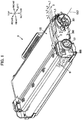
- the developing cartridge 8 includes a developing roller 81, a casing 100, a first gear cover 200, a second gear cover 600, and a detection gear 300.
- the detection gear 300 includes a protrusion 301.
- the developing cartridge 8 illustrated in Figs. 1 and 2 is a high-capacity-type developing cartridge. Therefore, the detection gear 300 illustrated in Figs. 1 and 2 is a high-capacity-type detection gear.
- the first gear cover 200 and the second gear cover 600 may be integrally formed as a single gear cover.
- the protrusion 301 is rotatable together with the detection gear 300.
- the protrusion 301 extends in an axial direction.
- the protrusion 301 is exposed outside through the first gear cover 200.
- the detection gear 300 also includes a rotational shaft portion 310.
- the rotational shaft portion 310 is rotatable about a boss 155 that extends along a second axis CL2.
- the rotational shaft portion 310 extends in the axial direction.
- the rotational shaft portion 310 includes one end portion, and the other end portion that is separated from the one end portion in the axial direction.
- the protrusion 301 is positioned at the one end portion of the rotational shaft portion 310 in the axial direction.
- the protrusion 301 is positioned outside the rotational shaft portion 310 in a radial direction of the rotational shaft portion 310.
- the protrusion 301 is separated from the second axis CL2 in a radial direction of the detection gear 300.
- the structure of the protrusion 301 will be described later in detail.
- the developing roller 81 extends in the axial direction.
- the detection gear 300 is rotatable about the second axis CL2 that extends in the axial direction.
- the rotational shaft portion 310 is one example of a second columnar portion.
- the rotational shaft portion 310 is also one example of a second cylindrical portion.
- the rotational shaft portion 310 extends in the axial direction. Further, the rotational shaft portion 310 has a cylindrical shape that is centered on the second axis CL2. The rotational shaft portion 310 has a through-hole that extends in the axial direction. The through-hole has a circular shape when viewed in the axial direction. An inner diameter of the through-hole formed in the rotational shaft portion 310 is smaller than an outer diameter of a cylindrical portion 380 described later. As illustrated in Fig. 2 , the boss 155 extending in the axial direction is inserted through the through-hole formed in the rotational shaft portion 310. Accordingly, the detection gear 300 is rotatably supported on the boss 155. The rotational shaft portion 310 is also rotatable about the second axis CL2.
- the boss 155 is provided at a cap 150.
- the cap 150 is a separate member from the casing 100.
- the casing 100 has a fill hole 84A.
- the fill hole 84A is formed in a first outer surface 100A of the casing 100.
- the fill hole 84A is a hole provided for filling a toner-accommodating portion 84 with toner.
- the cap 150 is a cover for closing the fill hole 84A.
- the boss 155 is provided at the cap 150, but the present invention is not limited to this arrangement.
- the fill hole 84A need not be formed in the first outer surface 100A, and the cap 150 need not be positioned at the first outer surface 100A.
- the boss 155 may extend in the axial direction from the first outer surface 100A.
- the casing 100 includes the first outer surface 100A.
- a gear train including the detection gear 300 is positioned at the first outer surface 100A.
- the casing 100 also includes a second outer surface that is separated from the first outer surface 100A in the axial direction.
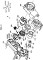
- An input gear 110, a developing roller gear 120, a supply roller gear 130, an idle gear 140, the detection gear 300, and a transmission gear 400 are positioned at the first outer surface 100A.
- the input gear 110, the developing roller gear 120, the supply roller gear 130, the idle gear 140, the detection gear 300, and the transmission gear 400 are rotatably positioned at the first outer surface 100A.
- the transmission gear 400 is one example of a first gear.
- the detection gear 300 is one example of a second gear.
- the input gear 110 has a coupling 101.
- the input gear 110 is rotatable together with the coupling 101.
- the coupling 101 is integrated with the input gear 110.
- the input gear 110 includes a plurality of gear teeth.
- the plurality of gear teeth of the input gear 110 are provided along a circumferential surface of the input gear 110.
- the coupling 101 is rotatable together with the input gear 110 when receiving a drive force from a motor (not illustrated) provided in an image forming apparatus.
- the coupling 101 includes a cylindrical portion 102, and a pair of protrusions 103.
- the cylindrical portion 102 has a cylindrical shape that extends in the axial direction.
- the pair of protrusions 103 protrudes inward from an inner circumferential surface of the cylindrical portion 102 in a radial direction of the cylindrical portion 102.
- the pair of protrusions 103 can engage with an apparatus-side coupling (not illustrated) provided in the image forming apparatus.
- the developing roller 81 includes a shaft 81A.
- the developing roller gear 120 is supported by the shaft 81A of the developing roller 81.
- the developing roller gear 120 is rotatable together with the shaft 81A.
- the developing roller gear 120 includes a plurality of gear teeth.
- the plurality of gear teeth of the developing roller gear 120 are provided along a circumferential surface of the developing roller gear 120. At least one of the plurality of gear teeth provided at the developing roller gear 120 meshes with at least one of the plurality of gear teeth provided at the input gear 110. Therefore, the developing roller gear 120 is rotatable in accordance with rotation of the input gear 110.
- a supply roller 83 includes a shaft 83A.
- the supply roller gear 130 is supported by the shaft 83A of the supply roller 83.
- the supply roller gear 130 is rotatable together with the shaft 83A.
- the supply roller gear 130 includes a plurality of gear teeth.
- the plurality of gear teeth of the supply roller gear 130 are provided along a circumferential surface of the supply roller gear 130. At least one of the plurality of gear teeth provided at the supply roller gear 130 meshes with at least one of the plurality of gear teeth provided at the input gear 110. Therefore, the supply roller gear 130 is rotatable in accordance with rotation of the input gear 110.
- the idle gear 140 includes a large-diameter gear portion 140A, and a small-diameter gear portion 140B.
- the large-diameter gear portion 140A is positioned separated farther than the small-diameter gear portion 140B from the first outer surface 100A in the axial direction.
- the small-diameter gear portion 140B includes a plurality of gear teeth.
- the plurality of gear teeth of the small-diameter gear portion 140B are provided along a circumferential surface of the small-diameter gear portion 140B.
- the large-diameter gear portion 140A includes a plurality of gear teeth.
- the plurality of gear teeth of the large-diameter gear portion 140A are provided along a circumferential surface of the large-diameter gear portion 140A. At least one of the plurality of gear teeth provided at the large-diameter gear portion 140A meshes with at least one of the plurality of gear teeth provided at the input gear 110. Therefore, the idle gear 140 is rotatable in accordance with rotation of the input gear 110.
- An addendum circle of the large-diameter gear portion 140A has an outer diameter greater than that of an addendum circle of the small-diameter gear portion 140B.
- the transmission gear 400 includes a large-diameter gear portion 440, and a small-diameter gear portion 450.
- the small-diameter gear portion 450 is positioned separated farther than the large-diameter gear portion 440 from the first outer surface 100A in the axial direction.
- the small-diameter gear portion 450 includes a plurality of gear teeth.
- the plurality of gear teeth of the small-diameter gear portion 450 are provided along a circumferential surface of the small-diameter gear portion 450.
- the large-diameter gear portion 440 includes a plurality of gear teeth.
- the plurality of gear teeth of the large-diameter gear portion 440 are provided along a circumferential surface of the large-diameter gear portion 440. At least one of the plurality of gear teeth provided at the large-diameter gear portion 440 meshes with at least one of the plurality of gear teeth provided at the small-diameter gear portion 140B. Therefore, the transmission gear 400 is rotatable in accordance with rotation of the idle gear 140. As illustrated in Fig. 2 , the transmission gear 400 is mounted to a shaft 85A of an agitator 85. The transmission gear 400 is rotatable together with the agitator 85.
- a distance in the axial direction between the first outer surface 100A and the small-diameter gear portion 450 is greater than a distance in the axial direction between the first outer surface 100A and the large-diameter gear portion 440.
- An addendum circle of the large-diameter gear portion 440 has an outer diameter greater than that of an addendum circle of the small-diameter gear portion 450.
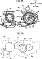
- the large-diameter gear portion 440 is rotatable about a first axis CL1 illustrated in Fig. 3B together with the small-diameter gear portion 450.
- the transmission gear 400 also includes a rotational shaft portion 430 and a first rib 460 in addition to the large-diameter gear portion 440 and the small-diameter gear portion 450.
- the rotational shaft portion 430, the large-diameter gear portion 440, the small-diameter gear portion 450, and the first rib 460 are an integrated component.
- the rotational shaft portion 430 has a cylindrical shape that is centered on the first axis CL1. In other words, the rotational shaft portion 430 has a cylindrical shape that extends in the axial direction. Note that the rotational shaft portion 430 may have a columnar shape that extends in the axial direction.
- the first rib 460 extends outward from the small-diameter gear portion 450 in a radial direction of the small-diameter gear portion 450. Specifically, the first rib 460 extends outward from the small-diameter gear portion 450 in the radial direction of the small-diameter gear portion 450 between one prescribed gear tooth on the small-diameter gear portion 450 and a gear tooth neighboring the prescribed gear tooth.
- the first rib 460 has a plate shape. A distal end of the first rib 460 is separated from the addendum circle of the small-diameter gear portion 450 in the radial direction of the small-diameter gear portion 450.
- the distal end of the first rib 460 is positioned between the addendum circle of the small-diameter gear portion 450 and the addendum circle of the large-diameter gear portion 440 in the radial direction of the small-diameter gear portion 450.
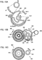
- the first rib 460 is in contact with a second rib 340 of the detection gear 300 and rotates the detection gear 300, after which a first gear portion 332 engages with the small-diameter gear portion 450, as illustrated in Figs. 14B and 15B .
- the first gear portion 332 becomes meshed with the small-diameter gear portion 450.
- the second rib 340 is positioned within a locus defined by the first rib 460 rotating about the first axis CL1.
- the first rib 460 is positioned separated downstream in a rotational direction of the transmission gear 400 from the second rib 340.
- the small-diameter gear portion 450 is not engaged with the first gear portion 332 in the initial position. Specifically, the small-diameter gear portion 450 does not mesh with the first gear portion 332 in the initial position.
- the large-diameter gear portion 440 is also not engaged with a second gear portion 352 in the initial position. Specifically, the large-diameter gear portion 440 does not mesh with the second gear portion 352 in the initial position.
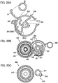
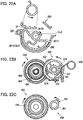
- the first gear portion 332 becomes engaged with the small-diameter gear portion 450, and the detection gear 300 rotates. Specifically, after the first rib 460 is in contact with the second rib 340 of the detection gear 300 and rotates the detection gear 300, the first gear portion 332 and the small-diameter gear portion 450 become meshed with each other, rotating the detection gear 300.
- the first gear portion 332 disengages from the small-diameter gear portion 450.
- the large-diameter gear portion 440 becomes engaged with the second gear portion 352, further rotating the detection gear 300.
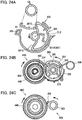
- the large-diameter gear portion 440 becomes disengaged from the second gear portion 352, and rotation of the detection gear 300 stops. More specifically, the first gear portion 332 becomes unmeshed from the small-diameter gear portion 450 after the detection gear 300 has rotated the prescribed angle.
- the large-diameter gear portion 440 becomes meshed with the second gear portion 352, and the detection gear 300 rotates further. Once the detection gear 300 has rotated a prescribed angle, the large-diameter gear portion 440 becomes unmeshed from the second gear portion 352, and rotation of the detection gear 300 stops, leaving the detection gear 300 in its final position.
- the toner-accommodating portion 84, the agitator 85, and the supply roller 83 are provided inside the casing 100.
- the toner-accommodating portion 84 is configured to accommodate developer.
- the developer is toner, for example.
- the agitator 85 is configured to agitate developer in the toner-accommodating portion 84.
- the supply roller 83 is a roller that can supply developer to the developing roller 81.
- the standard-type detection gear 300 is provided at a standard-type developing cartridge.
- a standard-type developing cartridge is a cartridge that has a smaller capacity for accommodating toner than a high-capacity-type developing cartridge.
- the protrusion 301 includes an outer circumferential surface 301A, as illustrated in Fig. 3A .
- the outer circumferential surface 301A extends along a portion of a circumference of the detection gear 300.
- the outer circumferential surface 301A has an arcuate shape centered on the second axis CL2.
- the outer circumferential surface 301A is positioned separated from the rotational shaft portion 310 in the radial direction of the detection gear 300.
- the protrusion 301 includes a first extension wall 301B, and a second extension wall 301C, as illustrated in Fig. 3A .
- the outer circumferential surface 301A includes a first end portion A1, and a second end portion A2.
- the first end portion A1 is one end portion of the outer circumferential surface 301A in a rotating direction of the detection gear 300.
- the second end portion A2 is the other end portion of the outer circumferential surface 301A separated from the first end portion A1 in the rotating direction of the detection gear 300.
- the first extension wall 301B extends inward from the first end portion A1 in the radial direction of the detection gear 300.
- first extension wall 301B extends from the first end portion A1 toward the rotational shaft portion 310 and is connected to the rotational shaft portion 310.
- the second extension wall 301C extends inward from the second end portion A2 in the radial direction of the detection gear 300.
- the second extension wall 301C extends from the second end portion A2 toward the rotational shaft portion 310 and is connected to the rotational shaft portion 310.
- the second extension wall 301C curves in a direction away from the outer circumferential surface 301A while extending from the second end portion A2 toward the rotational shaft portion 310.
- the second extension wall 301C is one example of an extension portion.
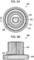
- the detection gear 300 further includes a flange portion 320, the first gear portion 332, the second gear portion 352, and the cylindrical portion 380.
- the second gear portion 352 is positioned at the other end portion of the rotational shaft portion 310. More specifically, the second gear portion 352 includes a plurality of gear teeth. The plurality of gear teeth of the second gear portion 352 are provided along a portion of a circumferential surface of the rotational shaft portion 310 in the rotating direction. Each of the plurality of gear teeth provided at the second gear portion 352 protrudes outward from the circumferential surface of the rotational shaft portion 310 in the radial direction of the rotational shaft portion 310.
- the circumferential surface of the rotational shaft portion 310 excluding the second gear portion 352 in the rotating direction is a second toothless portion 351.
- the second toothless portion 351 is a region in which no gear teeth are provided.
- the second gear portion 352 is one example of a second engaging portion.
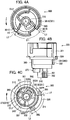
- the second gear portion 352 illustrated in Figs. 4A through 4C includes three gear teeth.
- the first gear portion 332 is positioned between the protrusion 301 and the second gear portion 352 in the axial direction. More specifically, the detection gear 300 further includes the cylindrical portion 380.
- the cylindrical portion 380 has a cylindrical shape that extends in the axial direction.
- the cylindrical portion 380 is positioned between the protrusion 301 and the second gear portion 352 in the axial direction.
- the cylindrical portion 380 has a cylindrical shape that is centered on the second axis CL2.
- An outer diameter of the cylindrical portion 380 is greater than an outer diameter of the rotational shaft portion 310.
- the first gear portion 332 is provided at a circumferential surface of the cylindrical portion 380. More specifically, the first gear portion 332 includes a plurality of gear teeth.
- the plurality of gear teeth of the first gear portion 332 are provided along a portion of the circumferential surface of the cylindrical portion 380.
- Each of the plurality of gear teeth provided at the first gear portion 332 protrudes outward from the circumferential surface of the cylindrical portion 380 in a radial direction of the cylindrical portion 380.
- the circumferential surface of the cylindrical portion 380 excluding the first gear portion 332 in the rotating direction is a first toothless portion 331.
- the first toothless portion 331 is a region in which no gear teeth are provided.
- the outer diameter of the cylindrical portion 380 is greater than the outer diameter of the rotational shaft portion 310.
- the first gear portion 332 is provided at a different position from the second gear portion 352 in the rotating direction of the detection gear 300.
- the second gear portion 352 is separated a prescribed distance from the first gear portion 332 in the rotating direction, as illustrated in Figs. 4B and 4C . That is, the second gear portion 352 is spaced apart from the first gear portion 332.
- an addendum circle of the first gear portion 332 has an outer diameter greater than that of an addendum circle of the second gear portion 352.
- a distance from the second axis CL2 to tips of the gear teeth provided at the first gear portion 332 is 11.5 mm
- a distance from the second axis CL2 to tips of the gear teeth provided at the second gear portion 352 is 6.7 mm.
- the first gear portion 332 is separated farther than the second gear portion 352 from the second axis CL2 in the radial direction of the detection gear 300.
- the first gear portion 332 is one example of a first engaging portion.
- the first gear portion 332 is engageable with the small-diameter gear portion 450 of the transmission gear 400 described later.
- the cylindrical portion 380 may have a columnar shape that extends in the axial direction.
- the cylindrical portion 380 is one example of a first columnar portion.
- the cylindrical portion 380 is also one example of s first cylindrical portion.
- the first gear portion 332 includes a third end portion 332A, and a fourth end portion 332B that is separated from the third end portion 332A in the rotating direction.
- the third end portion 332A is one end of the first gear portion 332 in a rotating direction of the first gear portion 332, and the fourth end portion 332B is the other end of the first gear portion 332 that is separated from the third end portion 332A in the rotating direction.
- the number of the plurality of gear teeth provided at the first gear portion 332 differs between the high-capacity-type developing cartridge and the standard-type developing cartridge.
- the first gear portion 332 includes ten gear teeth.
- an angle ⁇ 4 between a line segment L4 connecting the fourth end portion 332B and the second axis CL2 and a line segment L5 connecting the third end portion 332A and the second axis CL2 may be in the range from 73° to 78°. In the present embodiment, the angle ⁇ 4 is 74°. In the present embodiment, the number of the plurality of gear teeth provided at the first gear portion 332 is greater than the number of the plurality of gear teeth provided at the second gear portion 352.
- a locus defined by the rotating tips of the gear teeth of the second gear portion 352 is smaller than a locus defined by the rotating tips of the gear teeth of the first gear portion 332.
- the second gear portion 352 is positioned closer than the first gear portion 332 to the first outer surface 100A in the axial direction, and is engageable with the large-diameter gear portion 440 of the transmission gear 400.
- the second gear portion 352 is engageable with the large-diameter gear portion 440 after the first gear portion 332 has engaged with the small-diameter gear portion 450.
- the first gear portion 332 engages with the small-diameter gear portion 450, and subsequently the first gear portion 332 disengages from the small-diameter gear portion 450. After the first gear portion 332 disengages from the small-diameter gear portion 450, the second gear portion 352 engages with the large-diameter gear portion 440.
- the second gear portion 352 includes a fifth end portion 352A, and a sixth end portion 352B that is separated from the fifth end portion 352A in the rotating direction.
- the fifth end portion 352A is one end of the second gear portion 352 in the rotating direction of the second gear portion 352, and the sixth end portion 352B is the other end of the second gear portion 352 that is separated from the fifth end portion 352A in the rotating direction.
- the fifth end portion 352A is positioned closer than the sixth end portion 352B to the fourth end portion 332B in the rotating direction.
- an angle ⁇ 3 between the line segment L4 connecting the fourth end portion 332B and the second axis CL2 and a line segment L3 connecting the fifth end portion 352A and the second axis CL2 may be in the range from 35° to 41°.
- an angle ⁇ 6 between the line segment L3 connecting the fifth end portion 352A and the second axis CL2 and a line segment L6 connecting the sixth end portion 352B and the second axis CL2 may be in the range from 28° to 32°. In the present embodiment, ⁇ 3 is 38° and ⁇ 6 is 29°.
- the flange portion 320 has a disc shape.
- the flange portion 320 extends outward in the radial direction of the detection gear 300.
- the flange portion 320 is rotatable about the second axis CL2.
- the flange portion 320 is positioned separated farther in the axial direction than the first gear portion 332 from the first outer surface 100A.
- the flange portion 320 is also positioned separated farther in the axial direction than the second gear portion 352 from the first outer surface 100A.
- a distance in the axial direction between the first outer surface 100A and the first gear portion 332 is greater than a distance in the axial direction between the first outer surface 100A and the second gear portion 352.
- a distance in the axial direction between the first outer surface 100A and the flange portion 320 is greater than the distance in the axial direction between the first outer surface 100A and the first gear portion 332.
- the flange portion 320 includes a first surface facing the first outer surface 100A, and a second surface opposite to the first surface in the axial direction.
- the protrusion 301 is positioned at the second surface.
- the protrusion 301 protrudes from the second surface of the flange portion 320.
- the protrusion 301 protrudes in the axial direction and in a direction away from the first outer surface 100A.
- the protrusion 301 is rotatable together with the first gear portion 332 and the second gear portion 352.
- the cylindrical portion 380 extends toward the first outer surface 100A from the first surface of the flange portion 320.
- a portion of the rotational shaft portion 310 in the axial direction is positioned inside the cylindrical portion 380.
- the cylindrical portion 380 is provided along an outer circumferential surface of a portion of the rotational shaft portion 310 and surrounds the outer circumferential surface of the part of the rotational shaft portion 310.
- the boss 155 is inserted into an end portion of the rotational shaft portion 310 not surrounded by the cylindrical portion 380.
- the end portion of the rotational shaft portion 310 is positioned on the opposite side of the cylindrical portion 380 from the protrusion 301 in the axial direction.
- the end portion of the rotational shaft portion 310 is positioned on the opposite side of the cylindrical portion 380 in the axial direction from the outer circumferential surface 301A of the protrusion 301.
- a first protrusion 381 and a second protrusion 382 are positioned between the first gear portion 332 and the flange portion 320 in the axial direction.
- the first protrusion 381 protrudes farther outward in the radial direction of the cylindrical portion 380 than the tips of the plurality of gear teeth of the first gear portion 332.
- the second protrusion 382 also protrudes farther outward in the radial direction of the cylindrical portion 380 than the tips of the plurality of gear teeth of the first gear portion 332.
- the high-capacity-type developing cartridge 8 includes only the first protrusion 381, as illustrated in Fig. 5C . As illustrated in Fig.
- the rotational shaft portion 310 includes a rib 311.
- the rib 311 protrudes from the circumferential surface of the rotational shaft portion 310.
- Each of the plurality of gear teeth provided at the second gear portion 352 extends in the axial direction from the rib 311.
- the detection gear 300 further includes the second rib 340, a first restriction portion 360, and a spring-engaging portion 370.
- the spring-engaging portion 370 illustrated in Fig. 4B can be in contact with a torsion spring 500 illustrated in Fig. 7A .
- the spring-engaging portion 370 is positioned between the first gear portion 332 and the second gear portion 352 in the axial direction.
- the spring-engaging portion 370 is a protrusion that protrudes outward from the rotational shaft portion 310 in the radial direction of the rotational shaft portion 310.
- a length of the protrusion in the rotating direction is greater than a length of the second gear portion 352 in the rotating direction.
- the length of the protrusion in the rotating direction is greater than a length of the second rib 340 in the rotating direction.
- the spring-engaging portion 370 is positioned at the opposite side of the first gear portion 332 from the second axis CL2 and is positioned between the second gear portion 352 and the second rib 340 in the rotating direction.
- the spring-engaging portion 370 includes a third rib 371, a fourth rib 372, and a connecting rib 373.
- the third rib 371 protrudes outward from the outer circumferential surface of the rotational shaft portion 310 in the radial direction of the rotational shaft portion 310.
- the fourth rib 372 protrudes outward from the outer circumferential surface of the rotational shaft portion 310 in the radial direction of the rotational shaft portion 310.
- the fourth rib 372 is provided at a different position from the third rib 371 in the rotating direction.
- the connecting rib 373 connects a distal end of the third rib 371 in the radial direction of the rotational shaft portion 310 to a distal end of the fourth rib 372 in the radial direction of the rotational shaft portion 310.
- the connecting rib 373 has an arcuate shape centered on the second axis CL2.
- the second rib 340 is positioned between the first gear portion 332 and the second gear portion 352 in the axial direction.
- the second rib 340 is positioned at the opposite side of the second axis CL2 from the second gear portion 352.
- the second rib 340 is positioned at the outer circumferential surface of the rotational shaft portion 310.
- the second rib 340 extends outward from the outer circumferential surface of the rotational shaft portion 310 in the radial direction of the rotational shaft portion 310.
- the second rib 340 has a plate shape that extends outward from the rotational shaft portion 310 in the radial direction of the rotational shaft portion 310.
- a distal end of the second rib 340 is positioned between a circumferential surface of the first toothless portion 331 and the second gear portion 352 in the radial direction of the rotational shaft portion 310. Specifically, a distance between the distal end of the second rib 340 in the radial direction of the rotational shaft portion 310 and the second axis CL2 is approximately equal to a distance between the outer circumferential surface of the spring-engaging portion 370 and the second axis CL2.
- the first restriction portion 360 is a protrusion that protrudes from the circumferential surface of the cylindrical portion 380. A distal end of the first restriction portion 360 in the axial direction is positioned between the spring-engaging portion 370 and the flange portion 320. As illustrated in Fig. 4C , the first restriction portion 360 is positioned at the opposite side of the second axis CL2 from the first gear portion 332 and is also positioned between the second gear portion 352 and the second rib 340 in the rotating direction. The first restriction portion 360 includes one end portion, and the other end portion that is separated from the one end portion in the rotating direction.
- the one end portion of the first restriction portion 360 is positioned closer than the other end portion of the first restriction portion 360 to the second gear part 352 in the rotating direction.
- a surface of the other end portion of the first restriction portion 360 is in a plane perpendicular to the rotating direction, while a surface of the one end portion of the first restriction portion 360 is a sloped surface that slopes inward in the radial direction of the detection gear 300.
- the protrusion 301, the rotational shaft portion 310, the flange portion 320, the first gear portion 332, the second rib 340, the second gear portion 352, the first restriction portion 360, the spring-engaging portion 370, and the cylindrical portion 380 described above are configured as an integrated component.
- the developing cartridge 8 includes the torsion spring 500 and the cap 150.
- the torsion spring 500 is positioned at the first outer surface 100A.
- the cap 150 is positioned at the first outer surface 100A.
- the torsion spring 500 engages with the spring-engaging portion 370. Note that gear teeth provided at the large-diameter gear portion 440 have been omitted in Figs. 7A, 7B , and other drawings for convenience.
- the torsion spring 500 is a torsion coil spring.
- the torsion spring 500 includes a coil portion 501, a first arm 510, and a second arm 520. As illustrated in Fig. 7A , a boss extending in the axial direction from the first outer surface 100A is inserted into the coil portion 501. In other words, the coil portion 501 is wound around the boss extending in the axial direction from the first outer surface 100A.
- the first arm 510 extends from the coil portion 501. A distal end portion of the first arm 510 is in contact with a spring support portion 151 of the cap 150 described later.
- the second arm 520 extends toward the rotational shaft portion 310 from the coil portion 501. A distal end portion of the second arm 520 is in contact with the spring-engaging portion 370.
- the first arm 510 and the second arm 520 extend so as to cross each other.
- the second arm 520 is in contact with the spring-engaging portion 370. Accordingly, the torsion spring 500 urges the detection gear 300 relative to the boss 155. That is, at the initial position, the torsion spring 500 urges the third rib 371 of the spring-engaging portion 370 in a direction opposite to the rotating direction of the detection gear 300.
- the cap 150 includes the spring support portion 151, a restricting portion 152, a holding portion 153, and a base 154.
- the spring support portion 151 supports the first arm 510.
- the restricting portion 152 restricts rotation of the detection gear 300 in a clockwise direction when the detection gear 300 is at the initial position.
- the holding portion 153 holds the detection gear 300 at a prescribed inspection position.
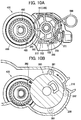
- the base 154 is plate shaped. As illustrated in Fig. 10A , the restricting portion 152 is in contact with the first restriction portion 360 of the detection gear 300 when the detection gear 300 is at the initial position.
- the first restriction portion 360 is urged toward the restricting portion 152. Accordingly, the restricting portion 152 restricts clockwise rotation of the detection gear 300, thereby properly placing the detection gear 300 at the initial position.
- the base 154 is positioned at the first outer surface 100A.
- the spring support portion 151 is a rib that protrudes in the axial direction from the base 154.
- the spring support portion 151 extends so as to conform to the shape of the first arm 510.
- the spring support portion 151 includes a first surface facing the rotational shaft portion 310, and a second surface on the side opposite to the first surface. The second surface of the spring support portion 151 is in contact with the first arm 510.
- the restricting portion 152 extends in the axial direction from the base 154.
- the holding portion 153 protrudes in the axial direction from the base 154.
- the holding portion 153 is a rib that extends in the axial direction.
- the holding portion 153 is arranged so as to face a circumferential surface of the detection gear 300. At its center portion, the holding portion 153 bends in a direction away from the detection gear 300.
- the restricting portion 152 and the holding portion 153 are positioned at the opposite side of the rotational shaft portion 310 from the spring support portion 151.
- the cap 150 also includes the boss 155.
- the boss 155 protrudes in the axial direction from the base 154.
- the boss 155 rotatably supports the rotational shaft portion 310 of the detection gear 300. Specifically, the boss 155 is inserted into a through-hole formed in the rotational shaft portion 310.
- the boss 155 is positioned inside the rotational shaft portion 310 of the detection gear 300.
- a position of the detection gear 300 when the detection gear 300 is mounted to the boss 155 will be described with reference to Figs. 8A and 8B . Further, a position of the detection gear 300 when inspecting the developing cartridge 8 having the detection gear 300 will be described with reference to Figs. 9A and 9B . Further, a position of the detection gear 300 when the developing cartridge 8 is shipped, i.e., when the developing cartridge 8 is new, will be described with reference to Figs. 10A and 10B .
- the detection gear 300 is moved to a mounting position in which the first restriction portion 360 is contacted by the holding portion 153 when the detection gear 300 is mounted to the boss 155.
- the restricting portion 152 and the holding portion 153 are deformed to hold the detection gear 300.
- the torsion spring 500 is in contact with the rotational shaft portion 310 and not in contact with the spring-engaging portion 370.
- the first gear cover 200 is mounted over the first outer surface 100A so as to cover at least a portion of the transmission gear 400.
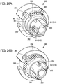
- a movement restricting portion 210 of the first gear cover 200 passes through a groove 302 formed in the detection gear 300 as illustrated in Fig. 26A , allowing the first gear cover 200 to be mounted to the first outer surface 100A.
- the detection gear 300 After the first gear cover 200 has been attached to the first outer surface 100A, an operator rotates the detection gear 300 clockwise, as illustrated in Fig. 9A .
- the detection gear 300 When the detection gear 300 is rotated, the first protrusion 381 of the detection gear 300 is in contact with the movement restricting portion 210 of the first gear cover 200, as illustrated in Fig. 9B . This contact halts the detection gear 300 at the inspection position.
- the first restriction portion 360 When the detection gear 300 is at the inspection position, the first restriction portion 360 is in contact with the holding portion 153 and is thus held by the holding portion 153.
- the second rib 340 is positioned outside the locus of the first rib 460. Hence, when the detection gear 300 is at the inspection position, the first rib 460 does not engage with the second rib 340, even if a drive force were applied to the developing cartridge 8. As a result, the detection gear 300 does not rotate.
- the operator rotates the detection gear 300 counterclockwise until the first restriction portion 360 is moved to the restricting portion 152, as illustrated in Figs. 10A and 10B .
- the detection gear 300 is moved to its initial position in which the first restriction portion 360 is in contact with the restricting portion 152.
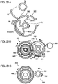
- the detection gear 300 is at the initial position illustrated in Figs. 14A through 14C .
- the small-diameter gear portion 450 is separated from the first gear portion 332.
- the small-diameter gear portion 450 is not engaged with the first gear portion 332.
- the small-diameter gear portion 450 is not meshed with the first gear portion 332.
- the large-diameter gear portion 440 is separated from the second gear portion 352. In other words, the large-diameter gear portion 440 is not engaged with the second gear portion 352.
- the large-diameter gear portion 440 is not meshed with the second gear portion 352.
- the torsion spring 500 urges the third rib 371 of the detection gear 300 so that the detection gear 300 is at the initial position.
- the initial position is one example of a first position.
- the second rib 340 is positioned within the locus of the first rib 460.
- the first gear portion 332 is positioned outside the locus of the small-diameter gear portion 450.
- the first gear cover 200 has an arcuate wall 220.
- the transmission gear 400 rotates and the first rib 460 rotates together with the transmission gear 400. While rotating, the first rib 460 is in contact with the second rib 340, as illustrated in Figs. 15A through 15C and rotates the second rib 340 against the urging force of the torsion spring 500. At this time, the detection gear 300 rotates together with the second rib 340.
- the detection gear 300 has rotated a prescribed amount, the first gear portion 332 becomes engaged with the small-diameter gear portion 450. Specifically, when the detection gear 300 has rotated the prescribed amount, the first gear portion 332 becomes meshed with the small-diameter gear portion 450.
- the first gear portion 332 rotates in accordance with the rotation of the small-diameter gear portion 450.
- the detection gear 300 further rotates a prescribed amount together with the first gear portion 332, as illustrated in Figs. 16A through 16C . Since the urging force of the torsion spring 500 presses the first gear portion 332 toward the small-diameter gear portion 450 at this time, the first gear portion 332 remains stably meshed with the small-diameter gear portion 450.
- the position of the detection gear 300 illustrated in Fig. 15B is one example of a second position.
- the small-diameter gear portion 450 becomes disengaged from the first gear portion 332, as illustrated in Figs. 17A through 17C . Specifically, the small-diameter gear portion 450 and the first gear portion 332 become unmeshed. After the small-diameter gear portion 450 and the first gear portion 332 become unmeshed, the large-diameter gear portion 440 engages with the second gear portion 352. Specifically, after the small-diameter gear portion 450 and the first gear portion 332 become unmeshed, the large-diameter gear portion 440 becomes meshed with the second gear portion 352. Thereafter, the second gear portion 352 rotates in accordance with the rotation of the large-diameter gear portion 440.
- the detection gear 300 further rotates a prescribed amount together with the second gear portion 352.
- the position of the detection gear 300 illustrated in Fig. 17B is one example of a third position.
- the torsion spring 500 is in contact with the fourth rib 372 of the spring-engaging portion 370 and urges the fourth rib 372 in the rotating direction.
- the urging force of the torsion spring 500 presses the second gear portion 352 toward the large-diameter gear portion 440.
- the second gear portion 352 can be reliably meshed with the large-diameter gear portion 440. Further, since the large-diameter gear portion 440 becomes meshed with the second gear portion 352 after the small-diameter gear portion 450 and the first gear portion 332 become unmeshed, reverse rotation of the detection gear 300 can be suppressed.
- the spring-engaging portion 370 presses the torsion spring 500 outward in the radial direction of the rotational shaft portion 310 while the detection gear 300 rotates from the position illustrated in Fig. 15B to the position illustrated in Fig. 16B .
- the torsion spring 500 presses the spring-engaging portion 370 toward the transmission gear 400. Consequently, the torsion spring 500 urges the detection gear 300 to rotate counterclockwise.
- the second gear portion 352 engages with the large-diameter gear portion 440, as illustrated in Figs. 18A through 18C .
- the second gear portion 352 meshes with the large-diameter gear portion 440.
- the second gear portion 352 rotates in accordance with the rotation of the large-diameter gear portion 440.
- the detection gear 300 rotates together with the second gear portion 352 while the second gear portion 352 is meshed with the large-diameter gear portion 440. Since the urging force of the torsion spring 500 presses the second gear portion 352 toward the large-diameter gear portion 440 at this time, the second gear portion 352 is stably meshed with the large-diameter gear portion 440.
- the detection gear 300 halts in the final position.
- the torsion spring 500 contacts the second rib 340 and urges the detection gear 300 to rotate counterclockwise.
- the second protrusion 382 is pressed toward the movement restricting portion 210, as illustrated by the dashed lines in Fig. 10B .
- the detection gear 300 is maintained at the final position since the second protrusion 382 is in contact with the movement restricting portion 210.
- the final position is one example of a fourth position.
- the second gear portion 352 is positioned outside the locus of the large-diameter gear portion 440.
- the second gear portion 352 becomes meshed with the large-diameter gear portion 440 before the protrusion 301 contacts an actuator 22, as illustrated in Figs. 17A through 17C .
- the high-capacity-type detection gear 300 will be described with reference to Figs. 5A through 5C, 7B, and 26B .
- the following description covers the points of difference between the high-capacity-type detection gear 300 and the standard-type detection gear 300, wherein the same reference numerals are assigned in each configuration to avoid duplicating description.
- a length of the first gear portion 332 of the high-capacity-type detection gear 300 in the rotating direction is greater than a length of the first gear portion 332 of the standard-type detection gear 300 in the rotating direction.
- the high-capacity-type first gear portion 332 includes a plurality of gear teeth whose number is greater than that of a plurality of gear teeth of the standard-type first gear portion 332.
- an angle ⁇ 5 between the line segment L4 connecting the fourth end portion 332B and the second axis CL2 and the line segment L5 connecting the third end portion 332A and the second axis CL2 may be in the range from 146° to 150°.
- ⁇ 5 is 147°.
- the standard-type detection gear 300 includes the first protrusion 381 and the second protrusion 382
- the high-capacity-type detection gear 300 includes only the first protrusion 381.
- the high-capacity-type spring-engaging portion 370 includes a third rib 374 and a fourth rib 375.
- the fourth rib 375 is positioned at the opposite side of the second rib 340 from the third rib 374 in the rotating direction. Further, the high-capacity-type third rib 374 is positioned at the upstream side of the second gear portion 352 in the rotating direction. Further, the fourth rib 375 is positioned at the opposite side of the second axis CL2 from the third rib 374.
- a position of the high-capacity-type detection gear 300 when the high-capacity-type detection gear 300 is mounted to the boss 155 will be described with reference to Figs. 11A and 11B . Further, a position of the high-capacity-type detection gear 300 when inspecting the developing cartridge 8 including the high-capacity-type detection gear 300 will be described with reference to Figs. 12A and 12B . Further, a position of the high-capacity-type detection gear 300 when the developing cartridge 8 is shipped, i.e., when the developing cartridge 8 is new, will be described with reference to Figs. 13A and 13B .
- the detection gear 300 is moved to the mounting position in which the first restriction portion 360 is contacted by the holding portion 153 when the detection gear 300 is mounted to the boss 155.
- the restricting portion 152 and the holding portion 153 are deformed to hold the detection gear 300.
- the torsion spring 500 is in contact with the rotational shaft portion 310 and not in contact with the spring-engaging portion 370.
- the first gear cover 200 is mounted over the first outer surface 100A so as to cover at least a portion of the transmission gear 400.
- the detection gear 300 By setting the detection gear 300 at the mounting position when attaching the first gear cover 200 to the first outer surface 100A, the movement restricting portion 210 on the first gear cover 200 passes through the groove 302 formed in the detection gear 300 as illustrated in Fig. 26B , allowing the first gear cover 200 to be attached to the first outer surface 100A.
- the detection gear 300 After the first gear cover 200 has been attached to the first outer surface 100A, an operator rotates the detection gear 300 clockwise, as illustrated in Fig. 12A .
- the detection gear 300 When the detection gear 300 is rotated, the first protrusion 381 of the detection gear 300 is in contact with the movement restricting portion 210 of the first gear cover 200, as illustrated in Fig. 12B . This contact halts the detection gear 300 at the inspection position.
- the first restriction portion 360 When the detection gear 300 is at the inspection position, the first restriction portion 360 is in contact with the holding portion 153 and is thus held by the holding portion 153.
- the second rib 340 is positioned outside the locus of the first rib 460. Hence, when the detection gear 300 is at the inspection position, the first rib 460 does not engage with the second rib 340, even if a drive force were applied to the developing cartridge 8. As a result, the detection gear 300 does not rotate.
- the operator rotates the detection gear 300 counterclockwise until the first restriction portion 360 is moved to the restricting portion 152, as illustrated in Figs. 13A .
- the detection gear 300 is moved to its initial position in which the first restriction portion 360 is in contact with the restricting portion 152.
- the torsion spring 500 When the detection gear 300 is at the initial position illustrated in Fig. 20B , the torsion spring 500 is engaged with the third rib 374. Specifically, the torsion spring 500 is in contact with the third rib 374. The torsion spring 500 urges the third rib 374 to rotate clockwise. When the detection gear 300 is subsequently rotated in the counterclockwise direction, the third rib 374 rotates against the urging force of the torsion spring 500, as illustrated in Fig. 21B .
- the torsion spring 500 becomes engaged with an arcuate wall 341 connecting the third rib 374 to the second rib 340, as illustrated in Fig. 22B .
- the torsion spring 500 comes into contact with the arcuate wall 341 connecting the third rib 374 to the second rib 340.
- the urging force of the torsion spring 500 is directed toward the center of the detection gear 300.
- the large-diameter gear portion 440 becomes meshed with the second gear portion 352, as illustrated in Fig. 23B .
- the torsion spring 500 is in contact with the second rib 340 when the meshed state of the transmission gear 400 and the detection gear 300 shifts from the small-diameter gear portion 450 being meshed with the first gear portion 332 to the large-diameter gear part 440 being meshed with the second gear portion 352. Since the torsion spring 500 urges the second rib 340, the second gear portion 352 is urged toward the large-diameter gear portion 440, thereby reliably meshing the second gear part 352 with the large-diameter gear portion 440.
- the detection gear 300 rotates while the torsion spring 500 is in contact with the fourth rib 375 of the detection gear 300, as illustrated in Fig. 24B .
- the rotation of the detection gear 300 halts in the final position with the torsion spring 500 contacting the fourth rib 375, urging the detection gear 300 toward the downstream side in the rotating direction. Consequently, the first protrusion 381 of the detection gear 300 is pressed against the movement restricting portion 210 so that the detection gear 300 is held at the final position, as illustrated in Fig. 13B .
- a control device provided in an image forming apparatus uses the protrusion 301 to determine whether the developing cartridge 8 is new.
- the control device of the image forming apparatus also uses the protrusion 301 for identifying specifications of the developing cartridge 8.
- new cartridge determination process and specification identification process according to the present embodiment will be described.
- the protrusion 301 is at the initial position illustrated in Fig. 14A .
- the outer circumferential surface 301A of the protrusion 301 can be in contact with the actuator 22 in the image forming apparatus.
- the actuator 22 is pivotally movably provided in the image forming apparatus.
- a photosensor provided in the image forming apparatus detects the pivotal movement of the actuator 22.
- the control device of the image forming apparatus determines that a developing cartridge 8 has been attached to the image forming apparatus based on a signal detected by the photosensor.
- the actuator 22 when a developing cartridge 8 is not attached to the image forming apparatus, the actuator 22 is at its normal position between a light-emitting element and a light-receiving element of the photosensor.
- the protrusion 301 When a developing cartridge 8 is attached to the image forming apparatus, the protrusion 301 is in contact with the actuator 22, causing the actuator 22 to pivot and move from the normal position to a contact position. While at the contact position, the actuator 22 is not positioned between the light-emitting element and the light-receiving element of the photosensor. Accordingly, the light-receiving element receives light from the light-emitting element, enabling the photosensor to detect an ON signal. When the photosensor detects an ON signal, the control device determines that a developing cartridge 8 has been attached to the image forming apparatus.
- the detection gear 300 rotates counterclockwise, as illustrated in Fig. 15A .
- the protrusion 301 rotates counterclockwise together with the detection gear 300.
- the detection gear 300 further rotates, the protrusion 301 separates from the actuator 22, as illustrated in Figs. 16A and 17A .
- the actuator 22 returns to its normal position illustrated in Fig. 17A , causing the photosensor to detect an OFF signal.
- the second extension wall 301C of the protrusion 301 comes into contact with the actuator 22 again, as illustrated in Fig. 18A .
- the outer circumferential surface 301A of the protrusion 301 is in contact with the actuator 22, as illustrated in Fig. 19A , and the photosensor once again detects an ON signal.
- the detection gear 300 moves from the position illustrated in Fig. 17A to the position illustrated in Fig. 18A
- the first gear portion 332 disengages from the small-diameter gear portion 450 and the second gear portion 352 becomes engaged with the large-diameter gear portion 440.
- the detection gear 300 moves from the position illustrated in Fig. 17A to the position illustrated in Fig.
- the small-diameter gear portion 450 and the first gear portion 332 become unmeshed from each other and the large-diameter gear portion 440 and the second gear portion 352 become meshed with each other. Then, the second gear portion 352 rotates in accordance with the rotation of the large-diameter gear portion 440 and the detection gear 300 rotates together with the second gear portion 352.
- the second gear portion 352 is positioned closer than the first gear portion 332 to the second axis CL2.
- the rotational speed of the detection gear 300 when the second gear portion 352 is meshed with the large-diameter gear portion 440 is faster than the rotational speed of the detection gear 300 when the first gear portion 332 is meshed with the small-diameter gear portion 450.
- the rotational speed of the detection gear 300 increases when the meshed state of the transmission gear 400 and the detection gear 300 shifts from the small-diameter gear portion 450 being meshed with the first gear portion 332 to the large-diameter gear portion 440 being meshed with the second gear portion 352.
- the detection gear 300 can supply a new signal to the image forming apparatus.
- the detection gear 300 is capable of supplying a new signal to the image forming apparatus by changing its rotational speed.
- the image forming apparatus can perform new product determination process and specification identification process using the new signal of the detection gear 300. That is, when the detection gear 300 is at the final position, a second portion 301E of the outer circumferential surface 301A is in contact with the actuator 22 in the image forming apparatus, as illustrated in Fig. 19A . In this way, when the photosensor detects the sequence of signals, an ON signal, an OFF signal, and an ON signal in this order, after a drive force is inputted into the developing cartridge 8, the control device determines that the attached developing cartridge 8 is a new cartridge.
- the detection gear 300 is disengaged from the transmission gear 400, thereby maintaining the protrusion 301 at the final position. Accordingly, when a developing cartridge 8 having its protrusion 301 at the final position is attached to an image forming apparatus, the outer circumferential surface 301A of the protrusion 301 is in contact with the actuator 22, and the photosensor detects an ON signal. Since the protrusion 301 does not move out of the final position thereafter, even when the developing cartridge 8 receives a drive force, the photosensor only detects an ON signal. In this case, the control device in the image forming apparatus determines that the developing cartridge 8 attached to the image forming apparatus is an old cartridge (a product that has been used at least once).
- a length from the first extension wall 301B to the second extension wall 301C in the rotating direction is determined according to the specification of the developing cartridge 8.
- a length of the outer circumferential surface 301A in the rotating direction is determined according to the specification of the developing cartridge 8.
- the length of the outer circumferential surface 301A in the rotating direction of the standard-type detection gear 300 is a first length illustrated in Fig. 4A , for example.
- an angle between a line segment L1 connecting the first end portion A1 of the standard-type outer circumferential surface 301A and the second axis CL2 and a line segment L2 connecting the second end portion A2 of the standard-type outer circumferential surface 301A and the second axis CL2 is a first angle ⁇ 1.
- the first angle ⁇ 1 may be in the range from 97° to 99°, for example. In the present embodiment, ⁇ 1 is 98°.
- the length of the outer circumferential surface 301A in the rotating direction of the high-capacity-type detection gear 300 illustrated in Fig. 5A is a second length longer than the first length.
- a second angle ⁇ 2 between the line segment L1 and the line segment L2 of the high-capacity-type detection gear 300 is greater than the first angle ⁇ 1.
- the second angle ⁇ 2 may be in the range from 188° to 190°, for example. In the present embodiment, ⁇ 2 is 189°.
- the length of the outer circumferential surface 301A in the rotating direction of the high-capacity-type detection gear 300 may be the first length. In this case, the length of the outer circumferential surface 301A in the rotating direction of the standard-type detection gear 300 is the second length.
- the developing cartridge 8 including the developing roller 81 is provided with the detection gear 300, but the present invention is not limited to this configuration.
- a toner cartridge that does not include a developing roller may be provided in a laser printer.
- the toner cartridge includes a toner-accommodating portion for accommodating toner.
- the first gear portion 332 includes a plurality of gear teeth
- the second gear portion 352 also includes a plurality of gear teeth.
- a friction member formed of a rubber or a sponge may be used in place of the plurality of gear teeth.
- a first friction member 333 may be a rubber or a sponge in place of the first gear portion 332, as illustrated in Fig. 27 , for example.
- the first friction member 333 may engage with the small-diameter gear portion 450 through friction.
- the first friction member 333 may be provided along a portion of the circumferential surface of the cylindrical portion 380.
- the first friction member 333 may engage with the small-diameter gear portion 450 through friction.
- the detection gear 300 may rotate by friction between the first friction member 333 and the small-diameter gear portion 450.
- a second friction member 353 may be a rubber or a sponge in place of the second gear portion 352.
- the second friction member 353 may engage with the large-diameter gear portion 440 through friction.
- the second friction member 353 may be provided along a portion of the circumferential surface of the rotational shaft portion 310.
- the second friction member 353 may engage with the large-diameter gear portion 440 through friction.
- the detection gear 300 may rotate by friction between the second friction member 353 and the large-diameter gear portion 440.
- the friction members described above may be used in place of the plurality of gear teeth of the large-diameter gear portion 440 and the plurality of gear teeth of the small-diameter gear portion 450.
- the first gear portion 332 and the first friction member 333 are one example of a first engaging portion.
- the second gear portion 352 and the second friction member 353 are one example of a second engaging portion.
- the protrusion 301 is integrally formed in the detection gear 300, but the present invention is not limited to this configuration.
- the protrusion 301 may be a separate component from the detection gear 300.
- the protrusion 301 may rotate together with the detection gear 300.
- the protrusion 301 may be a resinous film or a rubber plate, for example.
- the detection gear 300 includes a single protrusion 301, but the present invention is not limited to this configuration.
- the protrusion 301 may be configured of a plurality of protrusions spaced apart from each other in the rotating direction.
- the cap 150 includes the boss 155, and the detection gear 300 is rotatably supported at the boss 155.
- the boss 155 may be provided at a separate component from the cap 150.
- the separate component may be attached to the first outer surface 100A, and the detection gear 300 may be rotatably supported at the boss 155.
- the fill hole 84A may be formed in the second outer surface of the casing 100.
- the boss 155 protrudes from the cap 150, but the present invention is not limited to this configuration.
- the boss 155 may protrude from the first outer surface 100A.
- torsion spring 500 is used in the present embodiment, the present invention is not limited to this configuration.
- a coil spring, a leaf spring, an elastic resin, or other member may be used in place of the torsion spring 500.
- a through-hole is formed in the rotational shaft portion 310, but the present invention is not limited to this configuration.
- any hole into which the boss 155 may be inserted may be formed in the rotational shaft portion 310, and the boss 155 need not penetrate the rotational shaft portion 310 entirely.
- one or more gear teeth may be provided in place of the first toothless portion 331. However, the one or more gear teeth need not engage with the small-diameter gear portion 450 in this case.
- One or more gear teeth may also be provided in place of the second toothless portion 351, but the one or more gear teeth need not engage with the large-diameter gear portion 440.
- the detection gear 300 meshes with the transmission gear 400 mounted to the shaft 85A of the agitator 85.
- the detection gear 300 may mesh with a gear other than the transmission gear 400 mounted to the shaft 85A of the agitator 85.
- the second extension wall 301C need not be connected with the rotational shaft portion 310.
- the second extension wall 301C may be configured of a plurality of bosses.
Landscapes
- Physics & Mathematics (AREA)
- General Physics & Mathematics (AREA)
- Electrophotography Configuration And Component (AREA)
- Dry Development In Electrophotography (AREA)
Abstract
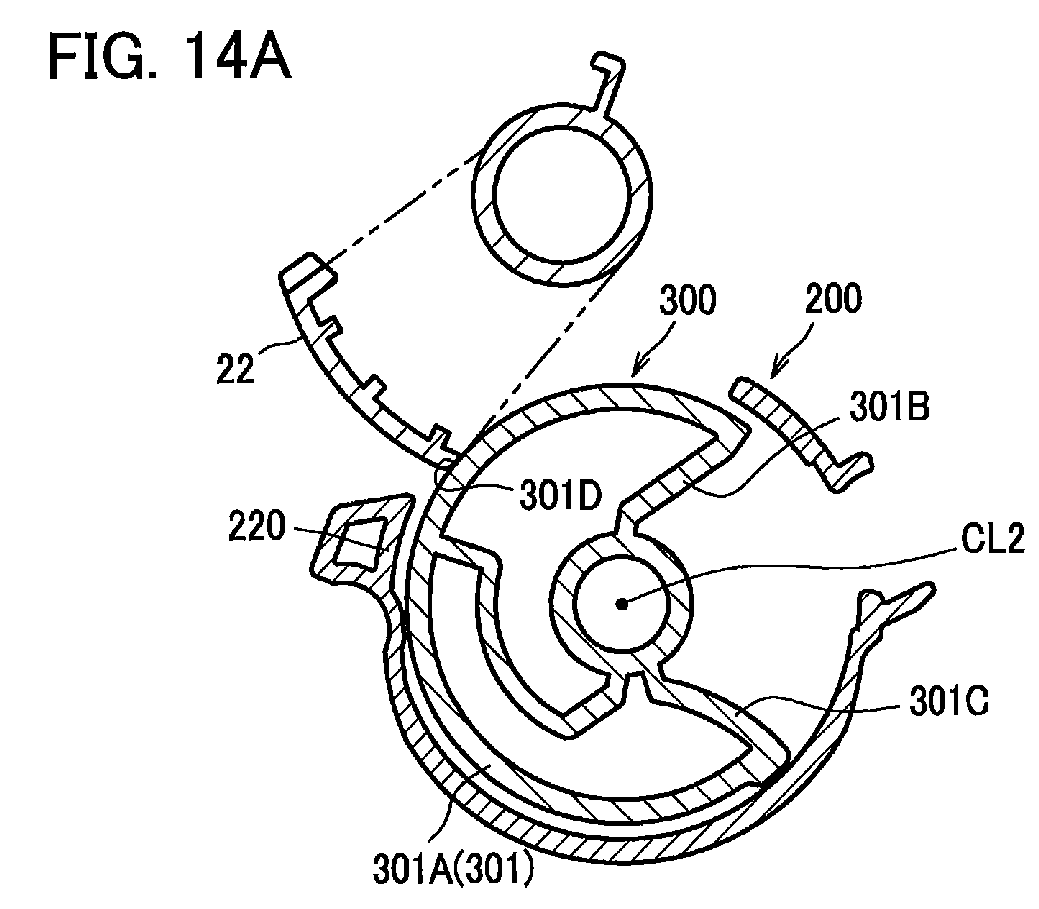

Description
- The present invention relates to a detection gear or a developing cartridge.
- A developing cartridge known in the art is provided with a detection gear including a protrusion (refer to Patent Literature 1, for example). There is also known an image forming apparatus provided with an actuator (refer to Patent Literature 1, for example). Specifically, when the developing cartridge is attached to the image forming apparatus and the developing cartridge subsequently receives a drive force from the image forming apparatus, the detection gear rotates. The rotation of the detection gear shifts the protrusion between a contact state in which the protrusion is in contact with the actuator, and a non-contact state in which the protrusion is not in contact with the actuator. These shifts between the contact state and the non-contact state of the protrusion, or the number of protrusions, indicate specifications of the developing cartridge.
- Patent Literature 1: Japanese Patent No.
4348632 - The inventors of the present invention have devised a new detection gear.
- It is an object of the present invention to provide a detection gear having a new configuration, or a developing cartridge provided with a detection gear having a new configuration.
- A developing cartridge may include a casing that can accommodate developer therein. Further, the developing cartridge may include a first gear rotatable about a first axis extending in an axial direction. Further, the first gear may include a small-diameter gear portion. Further, the first gear may include a large-diameter gear portion having a diameter greater than a diameter of the small-diameter gear portion. Further, the developing cartridge may include a second gear rotatable about a second axis extending in the axial direction. Further, the second gear may include a first columnar portion that extends in the axial direction and is centered on the second axis. Further, the second gear may include a second columnar portion that extends in the axial direction and is centered on the second axis and that has a diameter smaller than a diameter of the first columnar portion. Further, the second gear may include a first engaging portion that is provided along a portion of a circumferential surface of the first columnar portion and that is engageable with the small-diameter gear portion. Further, the second gear may include a second engaging portion that is provided along a portion of a circumferential surface of the second columnar portion and that is positioned closer to the casing in the axial direction than the first engaging portion to the casing in the axial direction and that is engageable with the large-diameter gear portion. Further, the second gear may include a protrusion that protrudes in the axial direction and that is rotatable together with the first engaging portion and the second engaging portion. Further, the second engaging portion may be capable of engaging with the large-diameter gear portion after the first engaging portion is engaged with the small-diameter gear portion.
- Further, the first engaging portion may include a plurality of gear teeth provided on a portion of the circumferential surface of the first columnar portion. Further, the second engaging portion may include a plurality of gear teeth provided on a portion of the circumferential surface of the second columnar portion. Further, the plurality of gear teeth of the first engaging portion of the developing cartridge may be capable of meshing with the small-diameter gear portion. Further, the plurality of gear teeth of the second engaging portion may be capable of meshing with the large-diameter gear portion.
- Alternatively, the first engaging portion may include a friction member provided along a portion of a circumference of the first columnar portion. The friction member may be a rubber.
- The second engaging portion may also include a friction member provided along a portion of a circumference of the second columnar portion. The friction member may be a rubber.
- The developing cartridge may further include an agitator that can agitate developer accommodated in the casing. Further, the first gear may be supported by a shaft of the agitator.
- Further, the small-diameter gear portion and the large-diameter gear portion may be rotatable about the first axis.
- Further, the second gear may include a flange that is positioned separated farther from the casing than the first engaging portion from the casing and that is rotatable about the second axis. Further, the protrusion may protrude from a surface of the flange opposite to a surface of the flange facing the casing.
- Further, the first columnar portion may have a cylindrical shape that extends in the axial direction.
- Further, a distance in the axial direction between an outer surface of the casing and the large-diameter gear portion may be smaller than a distance in the axial direction between an outer surface of the casing and the small-diameter gear portion.
- Further, the second columnar portion of the second gear may be rotatably supported by a boss that is positioned at an outer surface of the casing and that extends in the axial direction.
- Further, the boss may be a separate member from the casing.
- Further, the casing may have a fill hole for filling the casing with developer. Further, the casing may have a cap for closing the fill hole. Further, the cap may include the boss.
- Alternatively, the boss may protrude from the outer surface of the casing.
- Further, the developing cartridge may include a spring that is configured to be in contact with the second gear to urge the second gear in a rotating direction of the second gear after the first engaging portion is engaged with the small-diameter gear portion and until the second engaging portion becomes engaged with the large-diameter gear portion.
- Further, the spring may be in contact with the second gear at a position between the first engaging portion and the second engaging portion in the axial direction.
- Further, the spring may be a torsion coil spring.
- Further, the casing may have a fill hole through which developer is accommodated in the casing. Further, the casing may have a cap for closing the fill hole. Further, one end of the spring may be in contact with the cap while the other end of the spring may be in contact with the second gear.
- Further, the spring may have a first arm that includes the one end, and a second arm that includes the other end. Further, the first arm and the second arm may extend so as to cross each other.
- Further, the protrusion of the second gear may have an arcuate shape that extends in the rotating direction. Further, the protrusion may have a first end portion at one end in the rotating direction, and a second end portion at the opposite end from the first end portion in the rotating direction. Further, the protrusion may have an extension portion that extends from the second end portion toward the second axis.
- Further, the extension portion may be curved.
- Further, the extension portion may be connected to the second columnar portion.
- Further, an angle between a line segment connecting the first end portion and the second axis and a line segment connecting the second end portion and the second axis may be not smaller than 188° and not greater than 190°.
- Alternatively, an angle between a line segment connecting the first end portion and the second axis and a line segment connecting the second end portion and the second axis may be not smaller than 97° and not greater than 99°.
- Further, the first gear may include a first rib that extends in a radial direction of the first gear and that is rotatable together with the first gear. Further, the second gear may include a second rib that extends in a radial direction of the second gear and that is rotatable together with the second gear.
- Further, in a state where the second rib is positioned inside a locus of the first rib, the second gear may move from a first position in which the first engaging portion is positioned outside a locus of the small-diameter gear portion to a second position in which the first engaging portion is engaged with the small-diameter gear portion after the first rib becomes engaged with the second rib in accordance with rotation of the first gear.
- Further, the second gear may move from the second position to a third position in which the second engaging portion is engaged with the large-diameter gear portion. Further, the second gear may move from the third position to a fourth position in which the second engaging portion is positioned outside a locus of the large-diameter gear portion.
- Further, the second gear may include a third rib that protrudes outward from a circumferential surface in the radial direction of the second gear. Further, the spring may urge the third rib in a direction opposite to the rotating direction while the second gear is at the first position.
- Further, the casing may have a restricting portion that extends in the axial direction and that is configured to be in contact with the second gear and restrict movement of the second gear in the direction opposite to the rotating direction while the third rib is urged by the spring.
- Further, the third rib may be provided at a circumferential surface of the second columnar portion.
- Further, the second gear may include a fourth rib that protrudes outward in the radial direction of the second gear from a circumferential surface. Further, the spring may urge the fourth rib in the rotating direction while the second gear is at a prescribed position between the second position and the third position.
- Further, the fourth rib may be provided at the circumferential surface of the second columnar portion.
- Further, the third rib and the fourth rib may be positioned between the first engaging portion and the second engaging portion in the axial direction.
- Further, the second rib may be provided at the circumferential surface of the second columnar portion.
- Further, the protrusion may include a first portion that is configured to be in contact with a portion of an image forming apparatus when the second gear is at the first position. Further, the protrusion may include a second portion that is configured to be in contact with a portion of the image forming apparatus when the second gear is at the fourth position.
- Further, the first engaging portion may include a third end portion at one end in the rotating direction and a fourth end portion at the opposite end from the third end portion in the rotating direction. Further, the second engaging portion may include a fifth end portion at one end in the rotating direction and a sixth end portion at the opposite end from the fifth end portion in the rotating direction. Further, the fifth end portion may be positioned closer to the fourth end portion in the rotating direction than the sixth end portion to the fourth end portion in the rotating direction. Further, an angle between a line segment connecting the fourth end portion and the second axis and a line segment connecting the fifth end portion and the second axis may be not smaller than 35° and not greater than 41°.
- Further, an angle between the line segment connecting the fifth end portion and the second axis and a line segment connecting the sixth end portion and the second axis may be not smaller than 28° and not greater than 32°.
- Further, an angle between a line segment connecting the third end portion and the second axis and the line segment connecting the fourth end portion and the second axis may be not smaller than 146° and not greater than 150°.
- Alternatively, an angle between a line segment connecting the third end portion and the second axis and the line segment connecting the fourth end portion and the second axis may be not smaller than 73° and not greater than 78°.
- Further, the developing cartridge may include a developing roller that extends in the axial direction.
- A developing cartridge may include a casing that can accommodate developer therein. The developing cartridge may include a first gear that is rotatable about a first axis extending in an axial direction. Further, the first gear may include a small-diameter gear portion. Further, the first gear may include a large-diameter gear portion having a diameter greater than a diameter of the small-diameter gear portion.
- Further, the developing cartridge may include a second gear that is rotatable about a second axis extending in the axial direction. Further, the second gear may include a first engaging portion that is provided along a portion of a circumferential surface of the second gear and that is engageable with the small-diameter gear portion. Further, the second gear may include a second engaging portion that is provided at a position closer to the casing in the axial direction than the first engaging portion to the casing in the axial direction and that is provided along a portion of a circumferential surface of the second gear, the second engaging portion being provided at a position different from the first engaging portion in a rotating direction of the second gear and being engageable with the large-diameter gear portion after the first engaging portion is engaged with the small-diameter gear portion. Further, the second gear may include a protrusion that protrudes in the axial direction and that is rotatable together with the first engaging portion and the second engaging portion. Further, a locus defined by rotation of the second engaging portion may be smaller than a locus defined by rotation of the first engaging portion.
- Further, the first engaging portion may include a plurality of gear teeth provided on the portion of the circumferential surface of the second gear. Further, the second engaging portion may include a plurality of gear teeth provided on the portion of the circumferential surface of the second gear. The plurality of gear teeth of the first engaging portion may be capable of engaging with the small-diameter gear portion. Further, the plurality of gear teeth of the second engaging portion may be capable of engaging with the large-diameter gear portion.
- Alternatively, the first engaging portion may include a friction member that is engageable with the small-diameter gear portion through friction. The friction member may be a rubber.
- Further, the second engaging portion may include a friction member that is engageable with the large-diameter gear portion through friction. The friction member may be a rubber.
- The developing cartridge may further include an agitator that can agitate developer accommodated in the casing. Further, the first gear may be supported by a shaft of the agitator.
- Further, the small-diameter gear portion and the large-diameter gear portion may be rotatable about the first axis.
- Further, the second gear may include a flange that is positioned separated farther from the casing than the first engaging portion from the casing and that is rotatable about the second axis. Further, the protrusion may protrude from a surface of the flange opposite to a surface of the flange facing the casing.
- Further, the second gear may include a cylindrically shaped first columnar portion that extends in the axial direction and is centered on the second axis. Further, the first engaging portion may extend along a portion of a circumferential surface of the first columnar portion.
- Further, a distance in the axial direction between an outer surface of the casing and the large-diameter gear portion may be smaller than a distance in the axial direction between the outer surface of the casing and the small-diameter gear portion.
- Further, the second gear may include a second columnar portion that extends in the axial direction and is centered on the second axis, the second columnar portion having a diameter smaller than a dimeter of the first columnar portion.
- Further, the second columnar portion may be rotatably supported by a boss that is positioned at an outer surface of the casing and extends in the axial direction.
- Further, the boss may be a separate member from the casing.
- Further, the casing may have a fill hole for filling the casing with developer. Further, the casing may have a cap for closing the fill hole. Further, the cap may include the boss.
- Alternatively, the boss may protrude from the outer surface of the casing.
- Further, the developing cartridge may include a spring that is configured to be in contact with the second gear to urge the second gear in a rotating direction of the second gear after the first engaging portion is engaged with the small-diameter gear portion and until the second engaging portion becomes engaged with the large-diameter gear portion.
- Further, the spring may be in contact with the second gear at a position between the first engaging portion and the second engaging portion in the axial direction.
- Further, the spring may be a torsion coil spring.
- Further, the casing may have a fill hole through which developer is accommodated in the casing. Further, the casing may have a cap for closing the fill hole. Further, one end of the spring may be in contact with the cap while the other end of the spring may be in contact with the second gear.
- Further, the spring may have a first arm that includes the one end, and a second arm that includes the other end. Further, the first arm and the second arm may extend so as to cross each other.
- Further, the protrusion of the second gear may have an arcuate shape that extends in the rotating direction. Further, the protrusion may have a first end portion at one end in the rotating direction, and a second end portion at the opposite end from the first end portion in the rotating direction. Further, the protrusion may have an extension portion that extends from the second end portion toward the second axis.
- Further, the extension portion may be curved.
- Further, the extension portion may be connected to the second columnar portion.
- Further, an angle between a line segment connecting the first end portion and the second axis and a line segment connecting the second end portion and the second axis may be not smaller than 188° and not greater than 190°.
- Alternatively, an angle between a line segment connecting the first end portion and the second axis and a line segment connecting the second end portion and the second axis may be not smaller than 97° and not greater than 99°.
- Further, the first gear may include a first rib that extends in a radial direction of the first gear and that is rotatable together with the first gear. Further, the second gear may include a second rib that extends in a radial direction of the second gear and that is rotatable together with the second gear. Further, in a state where the second rib is positioned on a locus of the first rib, the second gear may move from a first position in which the first engaging portion is positioned outside a locus of the small-diameter gear portion to a second position in which the first engaging portion is engaged with the small-diameter gear portion after the first rib becomes engaged with the second rib in accordance with rotation of the first gear.
- Further, the second gear may move from the second position to a third position in which the second engaging portion is engaged with the large-diameter gear portion. Further, the second gear may move from the third position to a fourth position in which the second engaging portion is positioned outside a locus of the large-diameter gear portion.
- Further, the second gear may include a third rib that protrudes outward from a circumferential surface in the radial direction of the second gear. Further, the spring may urge the third rib in a direction opposite to the rotating direction while the second gear is at the first position.
- Further, the casing may have a restricting portion that extends in the axial direction and that is configured to be in contact with the second gear and restrict movement of the second gear in the direction opposite to the rotating direction while the third rib is urged by the spring.
- Further, the third rib may be provided at a circumferential surface of the second columnar portion.
- Further, the second gear may include a fourth rib that protrudes outward in the radial direction of the second gear from a circumferential surface. Further, the spring may urge the fourth rib in the rotating direction while the second gear is at a prescribed position between the second position and the third position.
- Further, the fourth rib may be provided at a circumferential surface of the second columnar portion.
- Further, the third rib and the fourth rib may be positioned between the first engaging portion and the second engaging portion in the axial direction.
- Further, the second rib may also be provided at a circumferential surface of the second columnar portion.
- Further, the protrusion may include a first portion that is configured to be in contact with a portion of an image forming apparatus when the second gear is at the first position. Further, the protrusion may include a second portion that is configured to be in contact with a portion of the image forming apparatus when the second gear is at the fourth position.
- Further, the first engaging portion may include a third end portion at one end in the rotating direction and a fourth end portion at the opposite end from the third end portion in the rotating direction. Further, the second engaging portion may include a fifth end portion at one end in the rotating direction and a sixth end portion at the opposite end from the fifth end portion in the rotating direction. Further, the fifth end portion may be positioned closer to the fourth end portion in the rotating direction than the sixth end portion to the fourth end portion in the rotating direction.
- Further, an angle between a line segment connecting the fourth end portion and the second axis and a line segment connecting the fifth end portion and the second axis may be not smaller than 35° and not greater than 41°.
- Further, an angle between the line segment connecting the fifth end portion and the second axis and a line segment connecting the sixth end portion and the second axis may be not smaller than 28° and not greater than 32°.
- Further, an angle between a line segment connecting the third end portion and the second axis and the line segment connecting the fourth end portion and the second axis may be not smaller than 146° and not greater than 150°.
- Alternatively, an angle between a line segment connecting the third end portion and the second axis and the line segment connecting the fourth end portion and the second axis may be not smaller than 73° and not greater than 78°.
- Further, the developing cartridge may include a developing roller that extends in the axial direction.
- A detection gear that is rotatable about an axis extending in an axial direction may include a protrusion that extends in the axial direction and that has an outer surface extending along a portion of a circumference of the detection gear. Further, the detection gear may include a first engaging portion that extends along a first portion of a circumference of the detection gear and that is positioned closer to the axis in a radial direction of the detection gear than the outer surface to the axis in the radial direction of the detection gear. Further, the detection gear may include a second engaging portion that extends along a second portion of a circumference of the detection gear different from the first portion and that is positioned closer to the axis in the radial direction than the first engaging portion to the axis in the radial direction.
- Further, the second engaging portion may be positioned at an opposite side of the outer surface with respect to the first engaging portion in the axial direction.
- Further, the detection gear may further include a first cylindrical portion having a first diameter. Further, the detection gear may include a second cylindrical portion having a second diameter smaller than the first diameter. The first engaging portion may extend along a portion of a circumferential surface of the first cylindrical portion in a rotating direction of the detection gear. The second engaging portion may extend along a portion of a circumferential surface of the second cylindrical portion in the rotating direction.
- Further, the second cylindrical portion may be positioned at an opposite side of the outer surface with respect to the first cylindrical portion.
- Further, the protrusion may protrude in the axial direction from the first cylindrical portion.
- Further, a length of the first engaging portion in the rotating direction may be greater than a length of the second engaging portion in the rotating direction.
- Further, the second engaging portion may be spaced apart from the first engaging portion in the rotating direction.
- Further, the first engaging portion may include a first end portion at one end in the rotating direction, and a second end portion separated from the first end portion in the rotating direction. Further, the second end portion may be positioned closer to the second engaging portion in the rotating direction than the first end portion to the second engaging portion in the rotating direction. Further, the second engaging portion may include a third end portion at one end in the rotating direction, and a fourth end portion separated from the third end portion in the rotating direction. Further, the third end portion may be positioned closer to the first engaging portion in the rotating direction than the fourth end portion to the first engaging portion in the rotating direction. Further, the second end portion and the third end portion may be spaced apart from each other in the rotating direction.
- Further, the first engaging portion may include a plurality of gear teeth provided along the first portion.
- Further, the second engaging portion may include a plurality of gear teeth provided along the second portion.
- Further, the first engaging portion may include a plurality of gear teeth provided along the first portion. Further, the second engaging portion may include a plurality of gear teeth provided along the second portion. Further, the number of the plurality of gear teeth of the first engaging portion may be greater than the number of the plurality of gear teeth of the second engaging portion.
- Alternatively, the first engaging portion may include a friction member provided along the first portion. Further, the friction member may be fa rubber.
- Further, the second engaging portion may include a friction member provided along the second portion.
- Further, the friction member may be a rubber.
- A detection gear that is rotatable about a first axis extending in an axial direction may include a protrusion that extends in the axial direction and that has an outer surface extending along a portion of a circumference of the detection gear. Further, the detection gear may include a first engaging portion that extends along a first portion of a circumference of the detection gear and that is positioned closer to the first axis in a radial direction of the detection gear than the outer surface to the first axis in the radial direction. Further, the detection gear may include a second engaging portion that extends along a second portion of a circumference of the detection gear different from the first portion and that is positioned closer to the first axis in the radial direction than the first engaging portion to the first axis in the radial direction.
- Further, the second engaging portion may be positioned at an opposite side of the outer surface with respect to the first engaging portion in the axial direction.
- Further, the detection gear may further include a first cylindrical portion having a first diameter. Further, the detection gear may include a second cylindrical portion having a second diameter smaller than the first diameter. Further, the first engaging portion may extend along a portion of a circumferential surface of the first cylindrical portion in a rotating direction of the detection gear. Further, the second engaging portion may extend along a portion of a circumferential surface of the second cylindrical portion in the rotating direction.
- Further, the second cylindrical portion may be positioned at an opposite side of the outer surface with respect to the first cylindrical portion.
- Further, the protrusion may protrude in the axial direction from the first cylindrical portion.
- Further, a length of the first engaging portion in the rotating direction may be greater than a length of the second engaging portion in the rotating direction.
- Further, the second engaging portion may be spaced apart from the first engaging portion in the rotating direction.
- Further, the first engaging portion may include a first end portion at one end in the rotating direction, and a second end portion separated from the first end portion in the rotating direction. Further, the second end portion may be positioned closer to the second engaging portion in the rotating direction than the first end portion to the second engaging portion in the rotating direction. Further, the second engaging portion may include a third end portion at one end in the rotating direction, and a fourth end portion separated from the third end portion in the rotating direction. Further, the third end portion may be positioned closer to the first engaging portion in the rotating direction than the fourth end portion to the first engaging portion in the rotating direction. Further, the second end portion and the third end portion may be spaced apart from each other in the rotating direction.
- Further, the first engaging portion may include a plurality of gear teeth provided along the first portion.
- Further, the second engaging portion may include a plurality of gear teeth provided along the second portion.
- Further, the first engaging portion may include a plurality of gear teeth provided along the first portion. Further, the second engaging portion may include a plurality of gear teeth provided along the second portion. Further, the number of the plurality of gear teeth of the first engaging portion may be greater than the number of the plurality of gear teeth of the second engaging portion.
- Alternatively, the first engaging portion may include a friction member provided along the first portion. Further, the friction member may be a rubber.
- Further, the second engaging portion may include a friction member provided along the second portion. Further, the friction member may be a rubber.
- Further, the developing cartridge may further include a small-diameter gear that is rotatable about a second axis extending in the axial direction, the small-diameter gear having a first diameter. Further, the developing cartridge may further include a large-diameter gear that is rotatable about the second axis, the large-diameter gear having a second diameter greater than the first diameter and being capable of rotating together with the small-diameter gear. Further, the second engaging portion may become engaged with the large-diameter gear after the first engaging portion is engaged with the small-diameter gear.
- Further, the developing cartridge may further include an agitator that extends in the axial direction and that includes a shaft extending in the axial direction. Further, the large-diameter gear and the small-diameter gear may be mounted to the shaft and may be capable of rotating together with rotation of the shaft.
- Further, the developing cartridge may further include a small-diameter gear that is rotatable about a second axis extending in the axial direction, the small-diameter gear having a first diameter. Further, the developing cartridge may further include a large-diameter gear that is rotatable about the second axis, the large-diameter gear having a second diameter greater than the first diameter being capable of rotating together with the small-diameter gear. Further, the first engaging portion may include a plurality of gear teeth provided along the first portion. Further, the second engaging portion may include a plurality of gear teeth provided along the second portion. Further, the plurality of gear teeth provided at the second engaging portion may become meshed with the large-diameter gear after the plurality of gear teeth provided at the first engaging portion is meshed with the small-diameter gear.
- Further, the developing cartridge may further include an agitator that extends in the axial direction and that include a shaft extending in the axial direction. Further, the large-diameter gear and the small-diameter gear may be mounted to the shaft and may be capable of rotating together with rotation of the shaft.
- Further, the outer surface may be configured to be in contact with a portion of an image forming apparatus when the developing cartridge is mounted in the image forming apparatus.
- Further, the developing cartridge may further include a small-diameter gear that is rotatable about a second axis extending in the axial direction, the small-diameter gear having a first diameter. Further, the developing cartridge may further include a large-diameter gear that is rotatable about the second axis, the large-diameter gear having a second diameter greater than the first diameter and being capable of rotating together with the small-diameter gear. Further, the second engaging portion may become engaged with the large-diameter gear after the first engaging portion is engaged with the small-diameter gear. Further, the detection gear may be capable of rotating from a first position in which the outer surface is in contact with a portion of the image forming apparatus to a second position in which the outer surface is not in contact with a portion of the image forming apparatus.
- Further, when the detection gear is at the second position, the first engaging portion may be engaged with the small-diameter gear, and the second engaging portion need not be engaged with the large-diameter gear.
- Further, the detection gear may further be capable of rotating from the second position to a third position in which the outer surface is in contact with a portion of the image forming apparatus. Further, when the detection gear is at the third position, the first engaging portion need not be engaged with the small-diameter gear. Further, the second engaging portion may be engaged with the large-diameter gear.
- Further, the first engaging portion may include a plurality of gear teeth provided along the first portion. Further, the second engaging portion may include a plurality of gear teeth provided along the second portion. Further, the plurality of gear teeth provided at the second engaging portion may become meshed with the large-diameter gear after the plurality of gear teeth provided at the first engaging portion is meshed with the small-diameter gear portion. Further, when the detection gear is at the second position, the plurality of gear teeth provided at the first engaging portion may be meshed with the small-diameter gear. Further, the plurality of gear teeth provided at the second engaging portion need not be meshed with the large-diameter gear.
- Further, the detection gear may be capable of further rotating from the second position to a third position in which the outer surface is in contact with a portion of the image forming apparatus. Further, when the detection gear is at the third position, the plurality of gear teeth provided at the first engaging portion need not be meshed with the small-diameter gear. Further, the plurality of gear teeth provided at the second engaging portion may be meshed with the large-diameter gear.
- Further, the developing cartridge may include a developing roller that extends in the axial direction.
- The rotational speed of the detection gear or the second gear when the second engaging portion is engaged with the large-diameter gear is faster than the rotational speed of the detection gear or the second gear when the first engaging portion is engaged with the small-diameter gear. Thus, when switching from the engagement between the small-diameter gear and the first engaging portion to the engagement between the large-diameter gear and the second engaging portion, the rotational speed of the detection gear or the second gear increases. Accordingly, the detection gear or the second gear can supply a new signal to the image forming apparatus. In this way, the invention can provide a detection gear or a second gear having a new configuration. In addition, the invention can provide a developing cartridge that includes a detection gear or a second gear having a new configuration.
-
-
Fig. 1 is one example of a perspective view illustrating a developingcartridge 8 according to one embodiment; -
Fig. 2 is one example of an exploded perspective view illustrating parts and components of the developingcartridge 8; -
Fig. 3A is an explanatory diagram for a cross section of the developingcartridge 8 taken along a line AA inFig. 1 ; -
Fig. 3B is an explanatory diagram of a gear mechanism provided in the developingcartridge 8; -
Fig. 4A is one example of a left side view of a standard-type detection gear 300; -
Fig. 4B is one example of a top plan view of the standard-type detection gear 300; -
Fig. 4C is one example of a right side view of the standard-type detection gear 300; -
Fig. 5A is one example of a left side view of a high-capacity-type detection gear 300; -
Fig. 5B is one example of a top plan view of the high-capacity-type detection gear 300; -
Fig. 5C is one example of a right side view of the high-capacity-type detection gear 300; -
Fig. 6A is one example of a left side view of atransmission gear 400; -
Fig. 6B is one example of a top plan view of thetransmission gear 400; -
Fig. 7A is an explanatory diagram for a standard-type spring-engagingportion 370 and atorsion spring 500 in relation to a cross section of the developingcartridge 8 taken along a line FF inFig. 1 ; -
Fig. 7B is an explanatory diagram for a high-capacity-type spring-engagingportion 370 and thetorsion spring 500 in relation to the cross section of the developingcartridge 8 taken along the line FF inFig. 1 ; -
Fig. 8A is an explanatory diagram illustrating a mounting position of the standard-type-type detection gear 300 in relation to a cross section of the developingcartridge 8 taken along a line DD inFig. 1 ; -
Fig. 8B is an explanatory diagram illustrating the mounting position of the standard-type detection gear 300 in relation to a cross section of the developingcartridge 8 taken along a line BB inFig. 1 ; -
Fig. 9A is an explanatory diagram illustrating an inspection position of thedetection gear 300 in relation to the cross section of the developingcartridge 8 taken along the line DD inFig. 1 ; -
Fig. 9B is an explanatory diagram illustrating the inspection position of thedetection gear 300 in relation to the cross section of the developingcartridge 8 taken along the line BB inFig. 1 ; -
Fig. 10A is an explanatory diagram illustrating an initial position of thedetection gear 300 in relation to the cross section of the developingcartridge 8 taken along the line DD inFig. 1 ; -
Fig. 10B is an explanatory diagram illustrating the initial position of thedetection gear 300 in relation to the cross section of the developingcartridge 8 taken along the line BB inFig. 1 ; -
Fig. 11A is an explanatory diagram illustrating a mounting position of the high-capacity-type detection gear 300 in relation to the cross section of the developingcartridge 8 taken along the line DD inFig. 1 ; -
Fig. 11B is an explanatory diagram illustrating the mounting position of the high-capacity-type detection gear 300 in relation to the cross section of the developingcartridge 8 taken along the line BB inFig. 1 ; -
Fig. 12A is an explanatory diagram illustrating an inspection position of the high-capacity-type detection gear 300 in relation to the cross section of the developingcartridge 8 taken along the line DD inFig. 1 ; -
Fig. 12B is an explanatory diagram illustrating the inspection position of the high-capacity-type detection gear 300 in relation to the cross section of the developingcartridge 8 taken along the line BB inFig. 1 ; -
Fig. 13A is an explanatory diagram illustrating an initial position of the high-capacity-type detection gear 300 in relation to the cross section of the developingcartridge 8 taken along the line DD inFig. 1 ; -
Fig. 13B is an explanatory diagram illustrating the initial position of the high-capacity-type detection gear 300 in relation to the cross section of the developingcartridge 8 taken along the line BB inFig. 1 ; -
Figs. 14A through 14C are explanatory diagrams for the standard-type detection gear 300, in which:-
Fig. 14A is an explanatory diagram illustrating a state of anactuator 22 in relation to the cross section of the developingcartridge 8 taken along the line AA inFig. 1 when the standard-type detection gear 300 is at the initial position; -
Fig. 14B is an explanatory diagram illustrating a state of thetransmission gear 400 and thedetection gear 300 in relation to a cross section of the developingcartridge 8 taken along a line CC inFig. 1 when the standard-type detection gear 300 is at the initial position; and -
Fig. 14C is an explanatory diagram illustrating a state of thetransmission gear 400 and thedetection gear 300 in relation to a cross section of the developingcartridge 8 taken along a line EE inFig. 1 when the standard-type detection gear 300 is at the initial position;
-
-
Figs 15A through 15C are explanatory diagrams for the standard-type detection gear 300, in which:-
Fig. 15A is an explanatory diagram illustrating a state of theactuator 22 in relation to the cross section of the developingcartridge 8 taken along the line AA inFig. 1 when afirst gear portion 332 is meshed with a small-diameter gear portion 450; -
Fig. 15B is an explanatory diagram illustrating a state of thetransmission gear 400 and thedetection gear 300 in relation to the cross section of the developingcartridge 8 taken along the line CC inFig. 1 when thefirst gear portion 332 is meshed with the small-diameter gear portion 450; and -
Fig. 15C is an explanatory diagram illustrating a state of thetransmission gear 400 and thedetection gear 300 in relation to the cross section of the developingcartridge 8 taken along the line EE inFig. 1 when thefirst gear portion 332 is meshed with the small-diameter gear portion 450;
-
-
Figs. 16A through 16C are explanatory diagrams for the standard-type detection gear 300, in which:-
Fig. 16A is an explanatory diagram illustrating a state of theactuator 22 in relation to the cross section of the developingcartridge 8 taken along the line AA inFig. 1 when aprotrusion 301 is separated from theactuator 22; -
Fig. 16B is an explanatory diagram illustrating a state of thetransmission gear 400 and thedetection gear 300 in relation to the cross section of the developingcartridge 8 taken along the line CC inFig. 1 when theprotrusion 301 is separated from theactuator 22; and -
Fig. 16C is an explanatory diagram illustrating a state of thetransmission gear 400 and thedetection gear 300 in relation to the cross section of the developingcartridge 8 taken along the line EE inFig. 1 when theprotrusion 301 is separated from theactuator 22;
-
-
Figs. 17A through 17C are explanatory diagrams for the standard-type detection gear 300, in which:-
Fig. 17A is an explanatory diagram illustrating a state of theactuator 22 in relation to the cross section of the developingcartridge 8 taken along the line AA inFig. 1 when thefirst gear portion 332 and the small-diameter gear portion 450 become unmeshed; -
Fig. 17B is an explanatory diagram illustrating a state of thetransmission gear 400 and thedetection gear 300 in relation to the cross section of the developingcartridge 8 taken along the line CC inFig. 1 when thefirst gear portion 332 and the small-diameter gear portion 450 become unmeshed; and -
Fig. 17C is an explanatory diagram illustrating a state of thetransmission gear 400 and thedetection gear 300 in relation to the cross section of the developingcartridge 8 taken along the line EE inFig. 1 when thefirst gear portion 332 and the small-diameter gear portion 450 become unmeshed;
-
-
Figs. 18A through 18C are explanatory diagrams for the standard-type detection gear 300, in which:-
Fig. 18A is an explanatory diagram illustrating a state of theactuator 22 in relation to the cross section of the developingcartridge 8 taken along the line AA inFig. 1 when asecond gear portion 352 is meshed with a large-diameter gear portion 440; -
Fig. 18B is an explanatory diagram illustrating a state of thetransmission gear 400 and thedetection gear 300 in relation to the cross section of the developingcartridge 8 taken along the line CC inFig. 1 when thesecond gear portion 352 is meshed with the large-diameter gear portion 440; and -
Fig. 18C is an explanatory diagram illustrating a state of thetransmission gear 400 and thedetection gear 300 in relation to the cross section of the developingcartridge 8 taken along the line EE inFig. 1 when thesecond gear portion 352 is meshed with the large-diameter gear portion 440;
-
-
Figs. 19A through 19C are explanatory diagrams for the standard-type detection gear 300, in which:-
Fig. 19A is an explanatory diagram illustrating a state of theactuator 22 in relation to the cross section of the developingcartridge 8 taken along the line AA inFig. 1 when thedetection gear 300 is at a final position; -
Fig. 19B is an explanatory diagram illustrating a state of thetransmission gear 400 and thedetection gear 300 in relation to the cross section of the developingcartridge 8 taken along the line CC inFig. 1 when thedetection gear 300 is at the final position; and -
Fig. 19C is an explanatory diagram illustrating a state of thetransmission gear 400 and thedetection gear 300 in relation to the cross section of the developingcartridge 8 taken along the line EE inFig. 1 when thedetection gear 300 is at the final position;
-
-
Figs. 20A through 20C are explanatory diagrams for the high-capacity-type detection gear 300, in which:-
Fig. 20A is an explanatory diagram illustrating a state of theactuator 22 in relation to the cross section of the developingcartridge 8 taken along the line AA inFig. 1 when the high-capacity-type detection gear 300 is at the initial position; -
Fig. 20B is an explanatory diagram illustrating a state of thetransmission gear 400 and thedetection gear 300 in relation to the cross section of the developingcartridge 8 taken along the line CC inFig. 1 when the high-capacity-type detection gear 300 is at the initial position; and -
Fig. 20C is an explanatory diagram illustrating a state of thetransmission gear 400 and thedetection gear 300 in relation to the cross section of the developingcartridge 8 taken along the line EE inFig. 1 when the high-capacity-type detection gear 300 is at the initial position;
-
-
Figs. 21A through 21C are explanatory diagrams for the high-capacity-type detection gear 300, in which:-
Fig. 21A is an explanatory diagram illustrating a state of theactuator 22 in relation to the cross section of the developingcartridge 8 taken along the line AA inFig. 1 when thefirst gear portion 332 is meshed with the small-diameter gear portion 450; -
Fig. 21B is an explanatory diagram illustrating a state of thetransmission gear 400 and thedetection gear 300 in relation to the cross section of the developingcartridge 8 taken along the line CC inFig. 1 when thefirst gear portion 332 is meshed with the small-diameter gear portion 450; and -
Fig. 21C is an explanatory diagram illustrating a state of thetransmission gear 400 and thedetection gear 300 in relation to the cross section of the developingcartridge 8 taken along the line EE inFig. 1 when thefirst gear portion 332 is meshed with the small-diameter gear portion 450;
-
-
Figs. 22A through 22C are explanatory diagrams for the high-capacity-type detection gear 300, in which:-
Fig. 22A is an explanatory diagram illustrating a state of theactuator 22 in relation to the cross section of the developingcartridge 8 taken along the line AA inFig. 1 when theprotrusion 301 is separated from theactuator 22; -
Fig. 22B is an explanatory diagram illustrating a state of thetransmission gear 400 and thedetection gear 300 in relation to the cross section of the developingcartridge 8 taken along the line CC inFig. 1 when theprotrusion 301 is separated from theactuator 22; and -
Fig. 22C is an explanatory diagram illustrating a state of thetransmission gear 400 and thedetection gear 300 in relation to the cross section of the developingcartridge 8 taken along the line EE inFig. 1 when theprotrusion 301 is separated from theactuator 22;
-
-
Figs. 23A through 23C are explanatory diagrams for the high-capacity-type detection gear 300, in which:-
Fig. 23A is an explanatory diagram illustrating a state of theactuator 22 in relation to the cross section of the developingcartridge 8 taken along the line AA inFig. 1 when thefirst gear portion 332 and the small-diameter gear portion 450 become unmeshed; -
Fig. 23B is an explanatory diagram illustrating a state of thetransmission gear 400 and thedetection gear 300 in relation to the cross section of the developingcartridge 8 taken along the line CC inFig. 1 when thefirst gear portion 332 and the small-diameter gear portion 450 become unmeshed; and -
Fig. 23C is an explanatory diagram illustrating a state of thetransmission gear 400 and thedetection gear 300 in relation to the cross section of the developingcartridge 8 taken along the line EE inFig. 1 when thefirst gear portion 332 and the small-diameter gear portion 450 become unmeshed;
-
-
Figs. 24A through 24C are explanatory diagrams for the high-capacity-type detection gear 300, in which:-
Fig. 24A is an explanatory diagram illustrating a state of theactuator 22 in relation to the cross section of the developingcartridge 8 taken along the line AA inFig. 1 when thesecond gear portion 352 is meshed with the large-diameter gear portion 440; -
Fig. 24B is an explanatory diagram illustrating a state of thetransmission gear 400 and thedetection gear 300 in relation to the cross section of the developingcartridge 8 taken along the line CC inFig. 1 when thesecond gear portion 352 is meshed with the large-diameter gear portion 440; and -
Fig. 24C is an explanatory diagram illustrating a state of thetransmission gear 400 and thedetection gear 300 in relation to the cross section of the developingcartridge 8 taken along the line EE inFig. 1 when thesecond gear portion 352 is meshed with the large-diameter gear portion 440;
-
-
Figs. 25A through 25C are explanatory diagrams for the high-capacity-type detection gear 300, in which:-
Fig. 25A is an explanatory diagram illustrating a state of theactuator 22 in relation to the cross section of the developingcartridge 8 taken along the line AA inFig. 1 when thedetection gear 300 is at the final position; -
Fig. 25B is an explanatory diagram illustrating a state of thetransmission gear 400 and thedetection gear 300 in relation to the cross section of the developingcartridge 8 taken along the line CC inFig. 1 when thedetection gear 300 is at the final position; and -
Fig. 25C is an explanatory diagram illustrating a state of thetransmission gear 400 and thedetection gear 300 in relation to the cross section of the developingcartridge 8 taken along the line EE inFig. 1 when thedetection gear 300 is at the final position;
-
-
Fig. 26A is a perspective view illustrating the standard-type detection gear 300; -
Fig. 26B is a perspective view illustrating the high-capacity-type detection gear 300; and -
Fig. 27 is illustrates a variation of gear teeth on thedetection gear 300. - Next, a detailed structure of a developing
cartridge 8 will be described while referring to the drawings. Directions used in the following description are based on the directions indicated inFig. 3 . - An overview of the developing
cartridge 8 will be described with reference toFigs. 1 and2 . As illustrated inFigs. 1 and2 , the developingcartridge 8 includes a developingroller 81, acasing 100, afirst gear cover 200, asecond gear cover 600, and adetection gear 300. - The
detection gear 300 includes aprotrusion 301. Note that the developingcartridge 8 illustrated inFigs. 1 and2 is a high-capacity-type developing cartridge. Therefore, thedetection gear 300 illustrated inFigs. 1 and2 is a high-capacity-type detection gear. Note also that thefirst gear cover 200 and thesecond gear cover 600 may be integrally formed as a single gear cover. Theprotrusion 301 is rotatable together with thedetection gear 300. Theprotrusion 301 extends in an axial direction. Theprotrusion 301 is exposed outside through thefirst gear cover 200. Thedetection gear 300 also includes arotational shaft portion 310. Therotational shaft portion 310 is rotatable about aboss 155 that extends along a second axis CL2. Therotational shaft portion 310 extends in the axial direction. Therotational shaft portion 310 includes one end portion, and the other end portion that is separated from the one end portion in the axial direction. Theprotrusion 301 is positioned at the one end portion of therotational shaft portion 310 in the axial direction. Theprotrusion 301 is positioned outside therotational shaft portion 310 in a radial direction of therotational shaft portion 310. Theprotrusion 301 is separated from the second axis CL2 in a radial direction of thedetection gear 300. The structure of theprotrusion 301 will be described later in detail. The developingroller 81 extends in the axial direction. Thedetection gear 300 is rotatable about the second axis CL2 that extends in the axial direction. Therotational shaft portion 310 is one example of a second columnar portion. Therotational shaft portion 310 is also one example of a second cylindrical portion. - As illustrated in
Fig. 2 , therotational shaft portion 310 extends in the axial direction. Further, therotational shaft portion 310 has a cylindrical shape that is centered on the second axis CL2. Therotational shaft portion 310 has a through-hole that extends in the axial direction. The through-hole has a circular shape when viewed in the axial direction. An inner diameter of the through-hole formed in therotational shaft portion 310 is smaller than an outer diameter of acylindrical portion 380 described later. As illustrated inFig. 2 , theboss 155 extending in the axial direction is inserted through the through-hole formed in therotational shaft portion 310. Accordingly, thedetection gear 300 is rotatably supported on theboss 155. Therotational shaft portion 310 is also rotatable about the second axis CL2. - As illustrated in
Fig. 2 , theboss 155 is provided at acap 150. Thecap 150 is a separate member from thecasing 100. Thecasing 100 has afill hole 84A. Specifically, thefill hole 84A is formed in a firstouter surface 100A of thecasing 100. Thefill hole 84A is a hole provided for filling a toner-accommodatingportion 84 with toner. Thecap 150 is a cover for closing thefill hole 84A. In the present embodiment, theboss 155 is provided at thecap 150, but the present invention is not limited to this arrangement. For example, thefill hole 84A need not be formed in the firstouter surface 100A, and thecap 150 need not be positioned at the firstouter surface 100A. In this case, theboss 155 may extend in the axial direction from the firstouter surface 100A. - As illustrated in
Fig. 2 , thecasing 100 includes the firstouter surface 100A. A gear train including thedetection gear 300 is positioned at the firstouter surface 100A. Thecasing 100 also includes a second outer surface that is separated from the firstouter surface 100A in the axial direction. Aninput gear 110, a developingroller gear 120, asupply roller gear 130, anidle gear 140, thedetection gear 300, and atransmission gear 400 are positioned at the firstouter surface 100A. Theinput gear 110, the developingroller gear 120, thesupply roller gear 130, theidle gear 140, thedetection gear 300, and thetransmission gear 400 are rotatably positioned at the firstouter surface 100A. Thetransmission gear 400 is one example of a first gear. Thedetection gear 300 is one example of a second gear. - As illustrated in
Figs. 1 and2 , theinput gear 110 has acoupling 101. Theinput gear 110 is rotatable together with thecoupling 101. Thecoupling 101 is integrated with theinput gear 110. Theinput gear 110 includes a plurality of gear teeth. The plurality of gear teeth of theinput gear 110 are provided along a circumferential surface of theinput gear 110. Thecoupling 101 is rotatable together with theinput gear 110 when receiving a drive force from a motor (not illustrated) provided in an image forming apparatus. Thecoupling 101 includes acylindrical portion 102, and a pair ofprotrusions 103. Thecylindrical portion 102 has a cylindrical shape that extends in the axial direction. The pair ofprotrusions 103 protrudes inward from an inner circumferential surface of thecylindrical portion 102 in a radial direction of thecylindrical portion 102. The pair ofprotrusions 103 can engage with an apparatus-side coupling (not illustrated) provided in the image forming apparatus. - The developing
roller 81 includes ashaft 81A. The developingroller gear 120 is supported by theshaft 81A of the developingroller 81. The developingroller gear 120 is rotatable together with theshaft 81A. The developingroller gear 120 includes a plurality of gear teeth. The plurality of gear teeth of the developingroller gear 120 are provided along a circumferential surface of the developingroller gear 120. At least one of the plurality of gear teeth provided at the developingroller gear 120 meshes with at least one of the plurality of gear teeth provided at theinput gear 110. Therefore, the developingroller gear 120 is rotatable in accordance with rotation of theinput gear 110. Asupply roller 83 includes ashaft 83A. Thesupply roller gear 130 is supported by theshaft 83A of thesupply roller 83. Thesupply roller gear 130 is rotatable together with theshaft 83A. Thesupply roller gear 130 includes a plurality of gear teeth. The plurality of gear teeth of thesupply roller gear 130 are provided along a circumferential surface of thesupply roller gear 130. At least one of the plurality of gear teeth provided at thesupply roller gear 130 meshes with at least one of the plurality of gear teeth provided at theinput gear 110. Therefore, thesupply roller gear 130 is rotatable in accordance with rotation of theinput gear 110. - The
idle gear 140 includes a large-diameter gear portion 140A, and a small-diameter gear portion 140B. The large-diameter gear portion 140A is positioned separated farther than the small-diameter gear portion 140B from the firstouter surface 100A in the axial direction. The small-diameter gear portion 140B includes a plurality of gear teeth. The plurality of gear teeth of the small-diameter gear portion 140B are provided along a circumferential surface of the small-diameter gear portion 140B. The large-diameter gear portion 140A includes a plurality of gear teeth. The plurality of gear teeth of the large-diameter gear portion 140A are provided along a circumferential surface of the large-diameter gear portion 140A. At least one of the plurality of gear teeth provided at the large-diameter gear portion 140A meshes with at least one of the plurality of gear teeth provided at theinput gear 110. Therefore, theidle gear 140 is rotatable in accordance with rotation of theinput gear 110. An addendum circle of the large-diameter gear portion 140A has an outer diameter greater than that of an addendum circle of the small-diameter gear portion 140B. - The
transmission gear 400 includes a large-diameter gear portion 440, and a small-diameter gear portion 450. The small-diameter gear portion 450 is positioned separated farther than the large-diameter gear portion 440 from the firstouter surface 100A in the axial direction. The small-diameter gear portion 450 includes a plurality of gear teeth. The plurality of gear teeth of the small-diameter gear portion 450 are provided along a circumferential surface of the small-diameter gear portion 450. The large-diameter gear portion 440 includes a plurality of gear teeth. The plurality of gear teeth of the large-diameter gear portion 440 are provided along a circumferential surface of the large-diameter gear portion 440. At least one of the plurality of gear teeth provided at the large-diameter gear portion 440 meshes with at least one of the plurality of gear teeth provided at the small-diameter gear portion 140B. Therefore, thetransmission gear 400 is rotatable in accordance with rotation of theidle gear 140. As illustrated inFig. 2 , thetransmission gear 400 is mounted to ashaft 85A of anagitator 85. Thetransmission gear 400 is rotatable together with theagitator 85. A distance in the axial direction between the firstouter surface 100A and the small-diameter gear portion 450 is greater than a distance in the axial direction between the firstouter surface 100A and the large-diameter gear portion 440. An addendum circle of the large-diameter gear portion 440 has an outer diameter greater than that of an addendum circle of the small-diameter gear portion 450. - Next, the structure of the
transmission gear 400 will be described with reference toFigs. 3B ,6A, and 6B . The large-diameter gear portion 440 is rotatable about a first axis CL1 illustrated inFig. 3B together with the small-diameter gear portion 450. As illustrated inFigs. 6A and 6B , thetransmission gear 400 also includes arotational shaft portion 430 and afirst rib 460 in addition to the large-diameter gear portion 440 and the small-diameter gear portion 450. Therotational shaft portion 430, the large-diameter gear portion 440, the small-diameter gear portion 450, and thefirst rib 460 are an integrated component. Therotational shaft portion 430 has a cylindrical shape that is centered on the first axis CL1. In other words, therotational shaft portion 430 has a cylindrical shape that extends in the axial direction. Note that therotational shaft portion 430 may have a columnar shape that extends in the axial direction. - The
first rib 460 extends outward from the small-diameter gear portion 450 in a radial direction of the small-diameter gear portion 450. Specifically, thefirst rib 460 extends outward from the small-diameter gear portion 450 in the radial direction of the small-diameter gear portion 450 between one prescribed gear tooth on the small-diameter gear portion 450 and a gear tooth neighboring the prescribed gear tooth. Thefirst rib 460 has a plate shape. A distal end of thefirst rib 460 is separated from the addendum circle of the small-diameter gear portion 450 in the radial direction of the small-diameter gear portion 450. The distal end of thefirst rib 460 is positioned between the addendum circle of the small-diameter gear portion 450 and the addendum circle of the large-diameter gear portion 440 in the radial direction of the small-diameter gear portion 450. - As will be described later in detail, the
first rib 460 is in contact with asecond rib 340 of thedetection gear 300 and rotates thedetection gear 300, after which afirst gear portion 332 engages with the small-diameter gear portion 450, as illustrated inFigs. 14B and15B . Specifically, after thefirst rib 460 is in contact with thesecond rib 340 of thedetection gear 300 and rotates thedetection gear 300, thefirst gear portion 332 becomes meshed with the small-diameter gear portion 450. Thus, when thedetection gear 300 is at an initial position illustrated inFig. 14B , thesecond rib 340 is positioned within a locus defined by thefirst rib 460 rotating about the first axis CL1. Specifically, in the initial position illustrated inFig. 14B , thefirst rib 460 is positioned separated downstream in a rotational direction of thetransmission gear 400 from thesecond rib 340. Further, as illustrated inFig. 14B , the small-diameter gear portion 450 is not engaged with thefirst gear portion 332 in the initial position. Specifically, the small-diameter gear portion 450 does not mesh with thefirst gear portion 332 in the initial position. As illustrated inFig. 14C , the large-diameter gear portion 440 is also not engaged with asecond gear portion 352 in the initial position. Specifically, the large-diameter gear portion 440 does not mesh with thesecond gear portion 352 in the initial position. - After the
first rib 460 is in contact with thesecond rib 340 of thedetection gear 300 and rotates thedetection gear 300, thefirst gear portion 332 becomes engaged with the small-diameter gear portion 450, and thedetection gear 300 rotates. Specifically, after thefirst rib 460 is in contact with thesecond rib 340 of thedetection gear 300 and rotates thedetection gear 300, thefirst gear portion 332 and the small-diameter gear portion 450 become meshed with each other, rotating thedetection gear 300. - Once the
detection gear 300 has rotated a prescribed angle, thefirst gear portion 332 disengages from the small-diameter gear portion 450. After thefirst gear portion 332 becomes disengaged from the small-diameter gear portion 450, the large-diameter gear portion 440 becomes engaged with thesecond gear portion 352, further rotating thedetection gear 300. Once thedetection gear 300 has rotated a prescribed angle, the large-diameter gear portion 440 becomes disengaged from thesecond gear portion 352, and rotation of thedetection gear 300 stops. More specifically, thefirst gear portion 332 becomes unmeshed from the small-diameter gear portion 450 after thedetection gear 300 has rotated the prescribed angle. Once thefirst gear portion 332 has become unmeshed from the small-diameter gear portion 450, the large-diameter gear portion 440 becomes meshed with thesecond gear portion 352, and thedetection gear 300 rotates further. Once thedetection gear 300 has rotated a prescribed angle, the large-diameter gear portion 440 becomes unmeshed from thesecond gear portion 352, and rotation of thedetection gear 300 stops, leaving thedetection gear 300 in its final position. - Note that the toner-accommodating
portion 84, theagitator 85, and thesupply roller 83 are provided inside thecasing 100. The toner-accommodatingportion 84 is configured to accommodate developer. The developer is toner, for example. Theagitator 85 is configured to agitate developer in the toner-accommodatingportion 84. Thesupply roller 83 is a roller that can supply developer to the developingroller 81. - Next, the detailed structure of a standard-
type detection gear 300 will be described with reference toFigs. 3A, 3B ,4A, 4B ,4C , and26A . Note that the gears have been illustrated in a simplified manner inFig. 3B . The standard-type detection gear 300 is provided at a standard-type developing cartridge. A standard-type developing cartridge is a cartridge that has a smaller capacity for accommodating toner than a high-capacity-type developing cartridge. - More specifically, the
protrusion 301 includes an outercircumferential surface 301A, as illustrated inFig. 3A . The outercircumferential surface 301A extends along a portion of a circumference of thedetection gear 300. In other words, the outercircumferential surface 301A has an arcuate shape centered on the second axis CL2. The outercircumferential surface 301A is positioned separated from therotational shaft portion 310 in the radial direction of thedetection gear 300. - Further, the
protrusion 301 includes afirst extension wall 301B, and asecond extension wall 301C, as illustrated inFig. 3A . The outercircumferential surface 301A includes a first end portion A1, and a second end portion A2. The first end portion A1 is one end portion of the outercircumferential surface 301A in a rotating direction of thedetection gear 300. The second end portion A2 is the other end portion of the outercircumferential surface 301A separated from the first end portion A1 in the rotating direction of thedetection gear 300. Thefirst extension wall 301B extends inward from the first end portion A1 in the radial direction of thedetection gear 300. Moreover, thefirst extension wall 301B extends from the first end portion A1 toward therotational shaft portion 310 and is connected to therotational shaft portion 310. Thesecond extension wall 301C extends inward from the second end portion A2 in the radial direction of thedetection gear 300. Moreover, thesecond extension wall 301C extends from the second end portion A2 toward therotational shaft portion 310 and is connected to therotational shaft portion 310. - The
second extension wall 301C curves in a direction away from the outercircumferential surface 301A while extending from the second end portion A2 toward therotational shaft portion 310. Thesecond extension wall 301C is one example of an extension portion. - As illustrated in
Figs. 4A through 4C andFig. 26A , thedetection gear 300 further includes aflange portion 320, thefirst gear portion 332, thesecond gear portion 352, and thecylindrical portion 380. - The
second gear portion 352 is positioned at the other end portion of therotational shaft portion 310. More specifically, thesecond gear portion 352 includes a plurality of gear teeth. The plurality of gear teeth of thesecond gear portion 352 are provided along a portion of a circumferential surface of therotational shaft portion 310 in the rotating direction. Each of the plurality of gear teeth provided at thesecond gear portion 352 protrudes outward from the circumferential surface of therotational shaft portion 310 in the radial direction of therotational shaft portion 310. The circumferential surface of therotational shaft portion 310 excluding thesecond gear portion 352 in the rotating direction is a secondtoothless portion 351. The secondtoothless portion 351 is a region in which no gear teeth are provided. Thesecond gear portion 352 is one example of a second engaging portion. Thesecond gear portion 352 illustrated inFigs. 4A through 4C includes three gear teeth. - The
first gear portion 332 is positioned between theprotrusion 301 and thesecond gear portion 352 in the axial direction. More specifically, thedetection gear 300 further includes thecylindrical portion 380. Thecylindrical portion 380 has a cylindrical shape that extends in the axial direction. Thecylindrical portion 380 is positioned between theprotrusion 301 and thesecond gear portion 352 in the axial direction. Thecylindrical portion 380 has a cylindrical shape that is centered on the second axis CL2. An outer diameter of thecylindrical portion 380 is greater than an outer diameter of therotational shaft portion 310. Thefirst gear portion 332 is provided at a circumferential surface of thecylindrical portion 380. More specifically, thefirst gear portion 332 includes a plurality of gear teeth. The plurality of gear teeth of thefirst gear portion 332 are provided along a portion of the circumferential surface of thecylindrical portion 380. Each of the plurality of gear teeth provided at thefirst gear portion 332 protrudes outward from the circumferential surface of thecylindrical portion 380 in a radial direction of thecylindrical portion 380. Further, the circumferential surface of thecylindrical portion 380 excluding thefirst gear portion 332 in the rotating direction is a firsttoothless portion 331. The firsttoothless portion 331 is a region in which no gear teeth are provided. The outer diameter of thecylindrical portion 380 is greater than the outer diameter of therotational shaft portion 310. Thefirst gear portion 332 is provided at a different position from thesecond gear portion 352 in the rotating direction of thedetection gear 300. More specifically, thesecond gear portion 352 is separated a prescribed distance from thefirst gear portion 332 in the rotating direction, as illustrated inFigs. 4B and 4C . That is, thesecond gear portion 352 is spaced apart from thefirst gear portion 332. Note that an addendum circle of thefirst gear portion 332 has an outer diameter greater than that of an addendum circle of thesecond gear portion 352. In the present embodiment, a distance from the second axis CL2 to tips of the gear teeth provided at thefirst gear portion 332 is 11.5 mm, while a distance from the second axis CL2 to tips of the gear teeth provided at thesecond gear portion 352 is 6.7 mm. Further, thefirst gear portion 332 is separated farther than thesecond gear portion 352 from the second axis CL2 in the radial direction of thedetection gear 300. Thefirst gear portion 332 is one example of a first engaging portion. Thefirst gear portion 332 is engageable with the small-diameter gear portion 450 of thetransmission gear 400 described later. Thecylindrical portion 380 may have a columnar shape that extends in the axial direction. Thecylindrical portion 380 is one example of a first columnar portion. Thecylindrical portion 380 is also one example of s first cylindrical portion. - As illustrated in
Fig. 4C , thefirst gear portion 332 includes athird end portion 332A, and afourth end portion 332B that is separated from thethird end portion 332A in the rotating direction. Thethird end portion 332A is one end of thefirst gear portion 332 in a rotating direction of thefirst gear portion 332, and thefourth end portion 332B is the other end of thefirst gear portion 332 that is separated from thethird end portion 332A in the rotating direction. The number of the plurality of gear teeth provided at thefirst gear portion 332 differs between the high-capacity-type developing cartridge and the standard-type developing cartridge. In the standard-type illustrated inFigs. 4A through 4C , thefirst gear portion 332 includes ten gear teeth. In the standard-type, an angle θ4 between a line segment L4 connecting thefourth end portion 332B and the second axis CL2 and a line segment L5 connecting thethird end portion 332A and the second axis CL2 may be in the range from 73° to 78°. In the present embodiment, the angle θ4 is 74°. In the present embodiment, the number of the plurality of gear teeth provided at thefirst gear portion 332 is greater than the number of the plurality of gear teeth provided at thesecond gear portion 352. - A locus defined by the rotating tips of the gear teeth of the
second gear portion 352 is smaller than a locus defined by the rotating tips of the gear teeth of thefirst gear portion 332. As illustrated inFig. 2 , thesecond gear portion 352 is positioned closer than thefirst gear portion 332 to the firstouter surface 100A in the axial direction, and is engageable with the large-diameter gear portion 440 of thetransmission gear 400. Thesecond gear portion 352 is engageable with the large-diameter gear portion 440 after thefirst gear portion 332 has engaged with the small-diameter gear portion 450. More specifically, thefirst gear portion 332 engages with the small-diameter gear portion 450, and subsequently thefirst gear portion 332 disengages from the small-diameter gear portion 450. After thefirst gear portion 332 disengages from the small-diameter gear portion 450, thesecond gear portion 352 engages with the large-diameter gear portion 440. - As illustrated in
Fig. 4C , thesecond gear portion 352 includes afifth end portion 352A, and asixth end portion 352B that is separated from thefifth end portion 352A in the rotating direction. Thefifth end portion 352A is one end of thesecond gear portion 352 in the rotating direction of thesecond gear portion 352, and thesixth end portion 352B is the other end of thesecond gear portion 352 that is separated from thefifth end portion 352A in the rotating direction. Thefifth end portion 352A is positioned closer than thesixth end portion 352B to thefourth end portion 332B in the rotating direction. The structure of thesecond gear portion 352 and the positional relationship between thesecond gear portion 352 and thefirst gear portion 332 is identical for both the standard-type detection gear and the high-capacity-type detection gear. Thus, the high-capacity-type detection gear illustrated inFig. 5C will be described in the following description. Specifically, as illustrated inFig. 5C , an angle θ3 between the line segment L4 connecting thefourth end portion 332B and the second axis CL2 and a line segment L3 connecting thefifth end portion 352A and the second axis CL2 may be in the range from 35° to 41°. Further, an angle θ6 between the line segment L3 connecting thefifth end portion 352A and the second axis CL2 and a line segment L6 connecting thesixth end portion 352B and the second axis CL2 may be in the range from 28° to 32°. In the present embodiment, θ3 is 38° and θ6 is 29°. - The
flange portion 320 has a disc shape. Theflange portion 320 extends outward in the radial direction of thedetection gear 300. Theflange portion 320 is rotatable about the second axis CL2. Theflange portion 320 is positioned separated farther in the axial direction than thefirst gear portion 332 from the firstouter surface 100A. Theflange portion 320 is also positioned separated farther in the axial direction than thesecond gear portion 352 from the firstouter surface 100A. In other words, a distance in the axial direction between the firstouter surface 100A and thefirst gear portion 332 is greater than a distance in the axial direction between the firstouter surface 100A and thesecond gear portion 352. Further, a distance in the axial direction between the firstouter surface 100A and theflange portion 320 is greater than the distance in the axial direction between the firstouter surface 100A and thefirst gear portion 332. - The
flange portion 320 includes a first surface facing the firstouter surface 100A, and a second surface opposite to the first surface in the axial direction. Theprotrusion 301 is positioned at the second surface. Theprotrusion 301 protrudes from the second surface of theflange portion 320. Specifically, theprotrusion 301 protrudes in the axial direction and in a direction away from the firstouter surface 100A. Note that theprotrusion 301 is rotatable together with thefirst gear portion 332 and thesecond gear portion 352. Thecylindrical portion 380 extends toward the firstouter surface 100A from the first surface of theflange portion 320. A portion of therotational shaft portion 310 in the axial direction is positioned inside thecylindrical portion 380. In other words, thecylindrical portion 380 is provided along an outer circumferential surface of a portion of therotational shaft portion 310 and surrounds the outer circumferential surface of the part of therotational shaft portion 310. Theboss 155 is inserted into an end portion of therotational shaft portion 310 not surrounded by thecylindrical portion 380. Hence, the end portion of therotational shaft portion 310 is positioned on the opposite side of thecylindrical portion 380 from theprotrusion 301 in the axial direction. Thus, the end portion of therotational shaft portion 310 is positioned on the opposite side of thecylindrical portion 380 in the axial direction from the outercircumferential surface 301A of theprotrusion 301. - As illustrated in
Fig. 4C , afirst protrusion 381 and asecond protrusion 382 are positioned between thefirst gear portion 332 and theflange portion 320 in the axial direction. Thefirst protrusion 381 protrudes farther outward in the radial direction of thecylindrical portion 380 than the tips of the plurality of gear teeth of thefirst gear portion 332. Thesecond protrusion 382 also protrudes farther outward in the radial direction of thecylindrical portion 380 than the tips of the plurality of gear teeth of thefirst gear portion 332. Note that the high-capacity-type developing cartridge 8 includes only thefirst protrusion 381, as illustrated inFig. 5C . As illustrated inFig. 26A , therotational shaft portion 310 includes arib 311. Therib 311 protrudes from the circumferential surface of therotational shaft portion 310. Each of the plurality of gear teeth provided at thesecond gear portion 352 extends in the axial direction from therib 311. - As illustrated in
Figs. 4A through 4C andFig. 26A , thedetection gear 300 further includes thesecond rib 340, afirst restriction portion 360, and a spring-engagingportion 370. - The spring-engaging
portion 370 illustrated inFig. 4B can be in contact with atorsion spring 500 illustrated inFig. 7A . The spring-engagingportion 370 is positioned between thefirst gear portion 332 and thesecond gear portion 352 in the axial direction. As illustrated inFig. 4C , the spring-engagingportion 370 is a protrusion that protrudes outward from therotational shaft portion 310 in the radial direction of therotational shaft portion 310. A length of the protrusion in the rotating direction is greater than a length of thesecond gear portion 352 in the rotating direction. Further, the length of the protrusion in the rotating direction is greater than a length of thesecond rib 340 in the rotating direction. The spring-engagingportion 370 is positioned at the opposite side of thefirst gear portion 332 from the second axis CL2 and is positioned between thesecond gear portion 352 and thesecond rib 340 in the rotating direction. - More specifically, the spring-engaging
portion 370 includes athird rib 371, afourth rib 372, and a connectingrib 373. Thethird rib 371 protrudes outward from the outer circumferential surface of therotational shaft portion 310 in the radial direction of therotational shaft portion 310. Thefourth rib 372 protrudes outward from the outer circumferential surface of therotational shaft portion 310 in the radial direction of therotational shaft portion 310. Thefourth rib 372 is provided at a different position from thethird rib 371 in the rotating direction. The connectingrib 373 connects a distal end of thethird rib 371 in the radial direction of therotational shaft portion 310 to a distal end of thefourth rib 372 in the radial direction of therotational shaft portion 310. The connectingrib 373 has an arcuate shape centered on the second axis CL2. - The
second rib 340 is positioned between thefirst gear portion 332 and thesecond gear portion 352 in the axial direction. Thesecond rib 340 is positioned at the opposite side of the second axis CL2 from thesecond gear portion 352. Thesecond rib 340 is positioned at the outer circumferential surface of therotational shaft portion 310. Thesecond rib 340 extends outward from the outer circumferential surface of therotational shaft portion 310 in the radial direction of therotational shaft portion 310. Specifically, thesecond rib 340 has a plate shape that extends outward from therotational shaft portion 310 in the radial direction of therotational shaft portion 310. A distal end of thesecond rib 340 is positioned between a circumferential surface of the firsttoothless portion 331 and thesecond gear portion 352 in the radial direction of therotational shaft portion 310. Specifically, a distance between the distal end of thesecond rib 340 in the radial direction of therotational shaft portion 310 and the second axis CL2 is approximately equal to a distance between the outer circumferential surface of the spring-engagingportion 370 and the second axis CL2. - As illustrated in
Fig. 4B , thefirst restriction portion 360 is a protrusion that protrudes from the circumferential surface of thecylindrical portion 380. A distal end of thefirst restriction portion 360 in the axial direction is positioned between the spring-engagingportion 370 and theflange portion 320. As illustrated inFig. 4C , thefirst restriction portion 360 is positioned at the opposite side of the second axis CL2 from thefirst gear portion 332 and is also positioned between thesecond gear portion 352 and thesecond rib 340 in the rotating direction. Thefirst restriction portion 360 includes one end portion, and the other end portion that is separated from the one end portion in the rotating direction. The one end portion of thefirst restriction portion 360 is positioned closer than the other end portion of thefirst restriction portion 360 to thesecond gear part 352 in the rotating direction. A surface of the other end portion of thefirst restriction portion 360 is in a plane perpendicular to the rotating direction, while a surface of the one end portion of thefirst restriction portion 360 is a sloped surface that slopes inward in the radial direction of thedetection gear 300. - The
protrusion 301, therotational shaft portion 310, theflange portion 320, thefirst gear portion 332, thesecond rib 340, thesecond gear portion 352, thefirst restriction portion 360, the spring-engagingportion 370, and thecylindrical portion 380 described above are configured as an integrated component. - As illustrated in
Fig. 7A , the developingcartridge 8 includes thetorsion spring 500 and thecap 150. Thetorsion spring 500 is positioned at the firstouter surface 100A. Thecap 150 is positioned at the firstouter surface 100A. Thetorsion spring 500 engages with the spring-engagingportion 370. Note that gear teeth provided at the large-diameter gear portion 440 have been omitted inFigs. 7A, 7B , and other drawings for convenience. - The
torsion spring 500 is a torsion coil spring. Thetorsion spring 500 includes acoil portion 501, a first arm 510, and asecond arm 520. As illustrated inFig. 7A , a boss extending in the axial direction from the firstouter surface 100A is inserted into thecoil portion 501. In other words, thecoil portion 501 is wound around the boss extending in the axial direction from the firstouter surface 100A. The first arm 510 extends from thecoil portion 501. A distal end portion of the first arm 510 is in contact with aspring support portion 151 of thecap 150 described later. Thesecond arm 520 extends toward therotational shaft portion 310 from thecoil portion 501. A distal end portion of thesecond arm 520 is in contact with the spring-engagingportion 370. The first arm 510 and thesecond arm 520 extend so as to cross each other. - In the initial position illustrated in
Fig. 7A , thesecond arm 520 is in contact with the spring-engagingportion 370. Accordingly, thetorsion spring 500 urges thedetection gear 300 relative to theboss 155. That is, at the initial position, thetorsion spring 500 urges thethird rib 371 of the spring-engagingportion 370 in a direction opposite to the rotating direction of thedetection gear 300. - The
cap 150 includes thespring support portion 151, a restrictingportion 152, a holdingportion 153, and abase 154. Thespring support portion 151 supports the first arm 510. The restrictingportion 152 restricts rotation of thedetection gear 300 in a clockwise direction when thedetection gear 300 is at the initial position. When inspecting thedetection gear 300, the holdingportion 153 holds thedetection gear 300 at a prescribed inspection position. Thebase 154 is plate shaped. As illustrated inFig. 10A , the restrictingportion 152 is in contact with thefirst restriction portion 360 of thedetection gear 300 when thedetection gear 300 is at the initial position. Specifically, with thesecond arm 520 urging thethird rib 371 in the clockwise direction (a direction opposite to the rotating direction of the detection gear 300), thefirst restriction portion 360 is urged toward the restrictingportion 152. Accordingly, the restrictingportion 152 restricts clockwise rotation of thedetection gear 300, thereby properly placing thedetection gear 300 at the initial position. - The
base 154 is positioned at the firstouter surface 100A. Thespring support portion 151 is a rib that protrudes in the axial direction from thebase 154. Thespring support portion 151 extends so as to conform to the shape of the first arm 510. Thespring support portion 151 includes a first surface facing therotational shaft portion 310, and a second surface on the side opposite to the first surface. The second surface of thespring support portion 151 is in contact with the first arm 510. The restrictingportion 152 extends in the axial direction from thebase 154. The holdingportion 153 protrudes in the axial direction from thebase 154. The holdingportion 153 is a rib that extends in the axial direction. The holdingportion 153 is arranged so as to face a circumferential surface of thedetection gear 300. At its center portion, the holdingportion 153 bends in a direction away from thedetection gear 300. The restrictingportion 152 and the holdingportion 153 are positioned at the opposite side of therotational shaft portion 310 from thespring support portion 151. Thecap 150 also includes theboss 155. Theboss 155 protrudes in the axial direction from thebase 154. Theboss 155 rotatably supports therotational shaft portion 310 of thedetection gear 300. Specifically, theboss 155 is inserted into a through-hole formed in therotational shaft portion 310. Theboss 155 is positioned inside therotational shaft portion 310 of thedetection gear 300. - Next, a position of the
detection gear 300 when thedetection gear 300 is mounted to theboss 155 will be described with reference toFigs. 8A and 8B . Further, a position of thedetection gear 300 when inspecting the developingcartridge 8 having thedetection gear 300 will be described with reference toFigs. 9A and 9B . Further, a position of thedetection gear 300 when the developingcartridge 8 is shipped, i.e., when the developingcartridge 8 is new, will be described with reference toFigs. 10A and 10B . - As illustrated in
Figs. 8A and 8B , thedetection gear 300 is moved to a mounting position in which thefirst restriction portion 360 is contacted by the holdingportion 153 when thedetection gear 300 is mounted to theboss 155. When thefirst restriction portion 360 is in contact with the holdingportion 153, the restrictingportion 152 and the holdingportion 153 are deformed to hold thedetection gear 300. Further, when thefirst restriction portion 360 is in contact with the holdingportion 153, thetorsion spring 500 is in contact with therotational shaft portion 310 and not in contact with the spring-engagingportion 370. - Next, the
first gear cover 200 is mounted over the firstouter surface 100A so as to cover at least a portion of thetransmission gear 400. By setting thedetection gear 300 at the mounting position when attaching thefirst gear cover 200 to the firstouter surface 100A, amovement restricting portion 210 of thefirst gear cover 200 passes through agroove 302 formed in thedetection gear 300 as illustrated inFig. 26A , allowing thefirst gear cover 200 to be mounted to the firstouter surface 100A. - After the
first gear cover 200 has been attached to the firstouter surface 100A, an operator rotates thedetection gear 300 clockwise, as illustrated inFig. 9A . When thedetection gear 300 is rotated, thefirst protrusion 381 of thedetection gear 300 is in contact with themovement restricting portion 210 of thefirst gear cover 200, as illustrated inFig. 9B . This contact halts thedetection gear 300 at the inspection position. When thedetection gear 300 is at the inspection position, thefirst restriction portion 360 is in contact with the holdingportion 153 and is thus held by the holdingportion 153. - When the
detection gear 300 is held at the inspection position in this way, thesecond rib 340 is positioned outside the locus of thefirst rib 460. Hence, when thedetection gear 300 is at the inspection position, thefirst rib 460 does not engage with thesecond rib 340, even if a drive force were applied to the developingcartridge 8. As a result, thedetection gear 300 does not rotate. - After inspecting the developing
cartridge 8, the operator rotates thedetection gear 300 counterclockwise until thefirst restriction portion 360 is moved to the restrictingportion 152, as illustrated inFigs. 10A and 10B . Hence, thedetection gear 300 is moved to its initial position in which thefirst restriction portion 360 is in contact with the restrictingportion 152. - Note that when the
detection gear 300 is rotated to its final position, thesecond protrusion 382 indicated by dashed lines inFig. 10B is in contact with themovement restricting portion 210. This contact holds thedetection gear 300 at the final position. - Next, operations of the
transmission gear 400 and thedetection gear 300 will be described. - When the developing
cartridge 8 is a new developing cartridge, thedetection gear 300 is at the initial position illustrated inFigs. 14A through 14C . When thedetection gear 300 is at the initial position, the small-diameter gear portion 450 is separated from thefirst gear portion 332. Hence, the small-diameter gear portion 450 is not engaged with thefirst gear portion 332. Specifically, the small-diameter gear portion 450 is not meshed with thefirst gear portion 332. Further, the large-diameter gear portion 440 is separated from thesecond gear portion 352. In other words, the large-diameter gear portion 440 is not engaged with thesecond gear portion 352. Specifically, the large-diameter gear portion 440 is not meshed with thesecond gear portion 352. Thetorsion spring 500 urges thethird rib 371 of thedetection gear 300 so that thedetection gear 300 is at the initial position. The initial position is one example of a first position. When thedetection gear 300 is at the initial position, thesecond rib 340 is positioned within the locus of thefirst rib 460. Further, when thedetection gear 300 is at the initial position, thefirst gear portion 332 is positioned outside the locus of the small-diameter gear portion 450. As illustrated inFig. 14A , thefirst gear cover 200 has anarcuate wall 220. - When the developing
cartridge 8 receives a drive force, thetransmission gear 400 rotates and thefirst rib 460 rotates together with thetransmission gear 400. While rotating, thefirst rib 460 is in contact with thesecond rib 340, as illustrated inFigs. 15A through 15C and rotates thesecond rib 340 against the urging force of thetorsion spring 500. At this time, thedetection gear 300 rotates together with thesecond rib 340. When thedetection gear 300 has rotated a prescribed amount, thefirst gear portion 332 becomes engaged with the small-diameter gear portion 450. Specifically, when thedetection gear 300 has rotated the prescribed amount, thefirst gear portion 332 becomes meshed with the small-diameter gear portion 450. Thereafter, thefirst gear portion 332 rotates in accordance with the rotation of the small-diameter gear portion 450. Thedetection gear 300 further rotates a prescribed amount together with thefirst gear portion 332, as illustrated inFigs. 16A through 16C . Since the urging force of thetorsion spring 500 presses thefirst gear portion 332 toward the small-diameter gear portion 450 at this time, thefirst gear portion 332 remains stably meshed with the small-diameter gear portion 450. Note that the position of thedetection gear 300 illustrated inFig. 15B is one example of a second position. - Subsequently, the small-
diameter gear portion 450 becomes disengaged from thefirst gear portion 332, as illustrated inFigs. 17A through 17C . Specifically, the small-diameter gear portion 450 and thefirst gear portion 332 become unmeshed. After the small-diameter gear portion 450 and thefirst gear portion 332 become unmeshed, the large-diameter gear portion 440 engages with thesecond gear portion 352. Specifically, after the small-diameter gear portion 450 and thefirst gear portion 332 become unmeshed, the large-diameter gear portion 440 becomes meshed with thesecond gear portion 352. Thereafter, thesecond gear portion 352 rotates in accordance with the rotation of the large-diameter gear portion 440. Thedetection gear 300 further rotates a prescribed amount together with thesecond gear portion 352. Note that the position of thedetection gear 300 illustrated inFig. 17B is one example of a third position. When thedetection gear 300 moves from the position illustrated inFig. 15B to the position illustrated inFig. 17B , thetorsion spring 500 is in contact with thefourth rib 372 of the spring-engagingportion 370 and urges thefourth rib 372 in the rotating direction. In this way, after thefirst gear portion 332 and the small-diameter gear portion 450 become unmeshed, the urging force of thetorsion spring 500 presses thesecond gear portion 352 toward the large-diameter gear portion 440. Accordingly, thesecond gear portion 352 can be reliably meshed with the large-diameter gear portion 440. Further, since the large-diameter gear portion 440 becomes meshed with thesecond gear portion 352 after the small-diameter gear portion 450 and thefirst gear portion 332 become unmeshed, reverse rotation of thedetection gear 300 can be suppressed. - More specifically, the spring-engaging
portion 370 presses thetorsion spring 500 outward in the radial direction of therotational shaft portion 310 while thedetection gear 300 rotates from the position illustrated inFig. 15B to the position illustrated inFig. 16B . When thedetection gear 300 reaches the position illustrated inFig. 16B , thetorsion spring 500 presses the spring-engagingportion 370 toward thetransmission gear 400. Consequently, thetorsion spring 500 urges thedetection gear 300 to rotate counterclockwise. - Next, the
second gear portion 352 engages with the large-diameter gear portion 440, as illustrated inFigs. 18A through 18C . Specifically, thesecond gear portion 352 meshes with the large-diameter gear portion 440. Accordingly, thesecond gear portion 352 rotates in accordance with the rotation of the large-diameter gear portion 440. Thedetection gear 300 rotates together with thesecond gear portion 352 while thesecond gear portion 352 is meshed with the large-diameter gear portion 440. Since the urging force of thetorsion spring 500 presses thesecond gear portion 352 toward the large-diameter gear portion 440 at this time, thesecond gear portion 352 is stably meshed with the large-diameter gear portion 440. When thesecond gear portion 352 becomes unmeshed from the large-diameter gear portion 440, as illustrated inFigs. 19A through 19C , thedetection gear 300 halts in the final position. When thedetection gear 300 is at its final position, thetorsion spring 500 contacts thesecond rib 340 and urges thedetection gear 300 to rotate counterclockwise. As a result, thesecond protrusion 382 is pressed toward themovement restricting portion 210, as illustrated by the dashed lines inFig. 10B . Thus, thedetection gear 300 is maintained at the final position since thesecond protrusion 382 is in contact with themovement restricting portion 210. Note that the final position is one example of a fourth position. When thedetection gear 300 is at the final position, thesecond gear portion 352 is positioned outside the locus of the large-diameter gear portion 440. - Further, the
second gear portion 352 becomes meshed with the large-diameter gear portion 440 before theprotrusion 301 contacts anactuator 22, as illustrated inFigs. 17A through 17C . - Next, the high-capacity-
type detection gear 300 will be described with reference toFigs. 5A through 5C, 7B, and 26B . The following description covers the points of difference between the high-capacity-type detection gear 300 and the standard-type detection gear 300, wherein the same reference numerals are assigned in each configuration to avoid duplicating description. - A length of the
first gear portion 332 of the high-capacity-type detection gear 300 in the rotating direction is greater than a length of thefirst gear portion 332 of the standard-type detection gear 300 in the rotating direction. In other words, the high-capacity-typefirst gear portion 332 includes a plurality of gear teeth whose number is greater than that of a plurality of gear teeth of the standard-typefirst gear portion 332. Specifically, as illustrated inFigs. 5A and 5C , an angle θ5 between the line segment L4 connecting thefourth end portion 332B and the second axis CL2 and the line segment L5 connecting thethird end portion 332A and the second axis CL2 may be in the range from 146° to 150°. In the high-capacity-type detection gear 300 illustrated inFigs. 5A and 5C , θ5 is 147°. Further, while the standard-type detection gear 300 includes thefirst protrusion 381 and thesecond protrusion 382, the high-capacity-type detection gear 300 includes only thefirst protrusion 381. - The high-capacity-type spring-engaging
portion 370 includes athird rib 374 and afourth rib 375. Thefourth rib 375 is positioned at the opposite side of thesecond rib 340 from thethird rib 374 in the rotating direction. Further, the high-capacity-typethird rib 374 is positioned at the upstream side of thesecond gear portion 352 in the rotating direction. Further, thefourth rib 375 is positioned at the opposite side of the second axis CL2 from thethird rib 374. - Next, a position of the high-capacity-
type detection gear 300 when the high-capacity-type detection gear 300 is mounted to theboss 155 will be described with reference toFigs. 11A and 11B . Further, a position of the high-capacity-type detection gear 300 when inspecting the developingcartridge 8 including the high-capacity-type detection gear 300 will be described with reference toFigs. 12A and 12B . Further, a position of the high-capacity-type detection gear 300 when the developingcartridge 8 is shipped, i.e., when the developingcartridge 8 is new, will be described with reference toFigs. 13A and 13B . - As illustrated in
Figs. 11A and 11B , thedetection gear 300 is moved to the mounting position in which thefirst restriction portion 360 is contacted by the holdingportion 153 when thedetection gear 300 is mounted to theboss 155. When thefirst restriction portion 360 is in contact with the holdingportion 153, the restrictingportion 152 and the holdingportion 153 are deformed to hold thedetection gear 300. Further, when thefirst restriction portion 360 is in contact with the holdingportion 153, thetorsion spring 500 is in contact with therotational shaft portion 310 and not in contact with the spring-engagingportion 370. - Next, the
first gear cover 200 is mounted over the firstouter surface 100A so as to cover at least a portion of thetransmission gear 400. By setting thedetection gear 300 at the mounting position when attaching thefirst gear cover 200 to the firstouter surface 100A, themovement restricting portion 210 on thefirst gear cover 200 passes through thegroove 302 formed in thedetection gear 300 as illustrated inFig. 26B , allowing thefirst gear cover 200 to be attached to the firstouter surface 100A. - After the
first gear cover 200 has been attached to the firstouter surface 100A, an operator rotates thedetection gear 300 clockwise, as illustrated inFig. 12A . When thedetection gear 300 is rotated, thefirst protrusion 381 of thedetection gear 300 is in contact with themovement restricting portion 210 of thefirst gear cover 200, as illustrated inFig. 12B . This contact halts thedetection gear 300 at the inspection position. When thedetection gear 300 is at the inspection position, thefirst restriction portion 360 is in contact with the holdingportion 153 and is thus held by the holdingportion 153. - When the
detection gear 300 is held at the inspection position in this way, thesecond rib 340 is positioned outside the locus of thefirst rib 460. Hence, when thedetection gear 300 is at the inspection position, thefirst rib 460 does not engage with thesecond rib 340, even if a drive force were applied to the developingcartridge 8. As a result, thedetection gear 300 does not rotate. - After inspecting the developing
cartridge 8, the operator rotates thedetection gear 300 counterclockwise until thefirst restriction portion 360 is moved to the restrictingportion 152, as illustrated inFigs. 13A . Hence, thedetection gear 300 is moved to its initial position in which thefirst restriction portion 360 is in contact with the restrictingportion 152. - Note that when the
detection gear 300 is rotated to its final position, thefirst protrusion 381 indicated by dashed lines inFig. 13B is in contact with themovement restricting portion 210. This contact holds thedetection gear 300 at the final position. - Next, operations of the high-capacity-
type detection gear 300 will be described with reference toFigs. 20A through 25C . Note that only operations differing from those for the standard-type detection gear 300 will be described with reference toFigs. 20A through 25C . - When the
detection gear 300 is at the initial position illustrated inFig. 20B , thetorsion spring 500 is engaged with thethird rib 374. Specifically, thetorsion spring 500 is in contact with thethird rib 374. Thetorsion spring 500 urges thethird rib 374 to rotate clockwise. When thedetection gear 300 is subsequently rotated in the counterclockwise direction, thethird rib 374 rotates against the urging force of thetorsion spring 500, as illustrated inFig. 21B . - When the
third rib 374 subsequently disengages from thetorsion spring 500, thetorsion spring 500 becomes engaged with anarcuate wall 341 connecting thethird rib 374 to thesecond rib 340, as illustrated inFig. 22B . Specifically, when thethird rib 374 and thetorsion spring 500 is no longer in contact with each other, thetorsion spring 500 comes into contact with thearcuate wall 341 connecting thethird rib 374 to thesecond rib 340. When thetorsion spring 500 is in contact with thearcuate wall 341, the urging force of thetorsion spring 500 is directed toward the center of thedetection gear 300. Next, after the small-diameter gear portion 450 and thefirst gear portion 332 become unmeshed, the large-diameter gear portion 440 becomes meshed with thesecond gear portion 352, as illustrated inFig. 23B . Thetorsion spring 500 is in contact with thesecond rib 340 when the meshed state of thetransmission gear 400 and thedetection gear 300 shifts from the small-diameter gear portion 450 being meshed with thefirst gear portion 332 to the large-diameter gear part 440 being meshed with thesecond gear portion 352. Since thetorsion spring 500 urges thesecond rib 340, thesecond gear portion 352 is urged toward the large-diameter gear portion 440, thereby reliably meshing thesecond gear part 352 with the large-diameter gear portion 440. - Thereafter, the
detection gear 300 rotates while thetorsion spring 500 is in contact with thefourth rib 375 of thedetection gear 300, as illustrated inFig. 24B . - As illustrated in
Fig. 25B , the rotation of thedetection gear 300 halts in the final position with thetorsion spring 500 contacting thefourth rib 375, urging thedetection gear 300 toward the downstream side in the rotating direction. Consequently, thefirst protrusion 381 of thedetection gear 300 is pressed against themovement restricting portion 210 so that thedetection gear 300 is held at the final position, as illustrated inFig. 13B . - A control device provided in an image forming apparatus uses the
protrusion 301 to determine whether the developingcartridge 8 is new. The control device of the image forming apparatus also uses theprotrusion 301 for identifying specifications of the developingcartridge 8. Hereinafter, new cartridge determination process and specification identification process according to the present embodiment will be described. - When the developing
cartridge 8 is a new cartridge, theprotrusion 301 is at the initial position illustrated inFig. 14A . When a new developingcartridge 8 is attached to an image forming apparatus, the outercircumferential surface 301A of theprotrusion 301 can be in contact with theactuator 22 in the image forming apparatus. Theactuator 22 is pivotally movably provided in the image forming apparatus. For example, when thedetection gear 300 is at the initial position, afirst portion 301D of the outercircumferential surface 301A is in contact with theactuator 22 in the image forming apparatus. When the outercircumferential surface 301A of theprotrusion 301 is in contact with theactuator 22, theactuator 22 pivotally moves, as illustrated inFig. 3A . A photosensor provided in the image forming apparatus detects the pivotal movement of theactuator 22. The control device of the image forming apparatus determines that a developingcartridge 8 has been attached to the image forming apparatus based on a signal detected by the photosensor. - Note that when a developing
cartridge 8 is not attached to the image forming apparatus, theactuator 22 is at its normal position between a light-emitting element and a light-receiving element of the photosensor. When a developingcartridge 8 is attached to the image forming apparatus, theprotrusion 301 is in contact with theactuator 22, causing theactuator 22 to pivot and move from the normal position to a contact position. While at the contact position, theactuator 22 is not positioned between the light-emitting element and the light-receiving element of the photosensor. Accordingly, the light-receiving element receives light from the light-emitting element, enabling the photosensor to detect an ON signal. When the photosensor detects an ON signal, the control device determines that a developingcartridge 8 has been attached to the image forming apparatus. - When a drive force is subsequently inputted into the developing
cartridge 8, thedetection gear 300 rotates counterclockwise, as illustrated inFig. 15A . Theprotrusion 301 rotates counterclockwise together with thedetection gear 300. When thedetection gear 300 further rotates, theprotrusion 301 separates from theactuator 22, as illustrated inFigs. 16A and17A . Next, theactuator 22 returns to its normal position illustrated inFig. 17A , causing the photosensor to detect an OFF signal. - Subsequently, the
second extension wall 301C of theprotrusion 301 comes into contact with theactuator 22 again, as illustrated inFig. 18A . Thereafter, the outercircumferential surface 301A of theprotrusion 301 is in contact with theactuator 22, as illustrated inFig. 19A , and the photosensor once again detects an ON signal. Specifically, as thedetection gear 300 moves from the position illustrated inFig. 17A to the position illustrated inFig. 18A , thefirst gear portion 332 disengages from the small-diameter gear portion 450 and thesecond gear portion 352 becomes engaged with the large-diameter gear portion 440. More specifically, as thedetection gear 300 moves from the position illustrated inFig. 17A to the position illustrated inFig. 18A , the small-diameter gear portion 450 and thefirst gear portion 332 become unmeshed from each other and the large-diameter gear portion 440 and thesecond gear portion 352 become meshed with each other. Then, thesecond gear portion 352 rotates in accordance with the rotation of the large-diameter gear portion 440 and thedetection gear 300 rotates together with thesecond gear portion 352. Thesecond gear portion 352 is positioned closer than thefirst gear portion 332 to the second axis CL2. Accordingly, the rotational speed of thedetection gear 300 when thesecond gear portion 352 is meshed with the large-diameter gear portion 440 is faster than the rotational speed of thedetection gear 300 when thefirst gear portion 332 is meshed with the small-diameter gear portion 450. Thus, the rotational speed of thedetection gear 300 increases when the meshed state of thetransmission gear 400 and thedetection gear 300 shifts from the small-diameter gear portion 450 being meshed with thefirst gear portion 332 to the large-diameter gear portion 440 being meshed with thesecond gear portion 352. Hence, thedetection gear 300 can supply a new signal to the image forming apparatus. Specifically, thedetection gear 300 is capable of supplying a new signal to the image forming apparatus by changing its rotational speed. More specifically, since the change in rotational speed of thedetection gear 300 can alter the timing at which theprotrusion 301 is in contact with theactuator 22, the image forming apparatus can perform new product determination process and specification identification process using the new signal of thedetection gear 300. That is, when thedetection gear 300 is at the final position, asecond portion 301E of the outercircumferential surface 301A is in contact with theactuator 22 in the image forming apparatus, as illustrated inFig. 19A . In this way, when the photosensor detects the sequence of signals, an ON signal, an OFF signal, and an ON signal in this order, after a drive force is inputted into the developingcartridge 8, the control device determines that the attached developingcartridge 8 is a new cartridge. - Further, when the
protrusion 301 is at the final position, thedetection gear 300 is disengaged from thetransmission gear 400, thereby maintaining theprotrusion 301 at the final position. Accordingly, when a developingcartridge 8 having itsprotrusion 301 at the final position is attached to an image forming apparatus, the outercircumferential surface 301A of theprotrusion 301 is in contact with theactuator 22, and the photosensor detects an ON signal. Since theprotrusion 301 does not move out of the final position thereafter, even when the developingcartridge 8 receives a drive force, the photosensor only detects an ON signal. In this case, the control device in the image forming apparatus determines that the developingcartridge 8 attached to the image forming apparatus is an old cartridge (a product that has been used at least once). - Further, a length from the
first extension wall 301B to thesecond extension wall 301C in the rotating direction is determined according to the specification of the developingcartridge 8. In other words, a length of the outercircumferential surface 301A in the rotating direction is determined according to the specification of the developingcartridge 8. Thus, when the photosensor detects an OFF signal for a first time duration, the control device determines that the attached developingcartridge 8 is a standard-type developing cartridge, for example. Thecasing 100 of a standard-type developing cartridge accommodates a standard amount of developer. Alternatively, when an OFF signal is detected for a second time duration longer than the first time duration, the control device determines that the mounted developingcartridge 8 is a high-capacity-type developing cartridge. Thecasing 100 of a high-capacity-type developing cartridge accommodates a large amount of developer than the standard amount. - Specifically, the length of the outer
circumferential surface 301A in the rotating direction of the standard-type detection gear 300 is a first length illustrated inFig. 4A , for example. In other words, an angle between a line segment L1 connecting the first end portion A1 of the standard-type outercircumferential surface 301A and the second axis CL2 and a line segment L2 connecting the second end portion A2 of the standard-type outercircumferential surface 301A and the second axis CL2 is a first angle θ1. The first angle θ1 may be in the range from 97° to 99°, for example. In the present embodiment, θ1 is 98°. - In contrast, the length of the outer
circumferential surface 301A in the rotating direction of the high-capacity-type detection gear 300 illustrated inFig. 5A is a second length longer than the first length. In other words, a second angle θ2 between the line segment L1 and the line segment L2 of the high-capacity-type detection gear 300 is greater than the first angle θ1. - The second angle θ2 may be in the range from 188° to 190°, for example. In the present embodiment, θ2 is 189°. Note that the length of the outer
circumferential surface 301A in the rotating direction of the high-capacity-type detection gear 300 may be the first length. In this case, the length of the outercircumferential surface 301A in the rotating direction of the standard-type detection gear 300 is the second length. - The present invention is not limited to the above-described embodiment. Various modifications and variations are conceivable as described below.
- In the present embodiment, the developing
cartridge 8 including the developingroller 81 is provided with thedetection gear 300, but the present invention is not limited to this configuration. For example, a toner cartridge that does not include a developing roller may be provided in a laser printer. The toner cartridge includes a toner-accommodating portion for accommodating toner. - In the present embodiment, the
first gear portion 332 includes a plurality of gear teeth, and thesecond gear portion 352 also includes a plurality of gear teeth. However, a friction member formed of a rubber or a sponge may be used in place of the plurality of gear teeth. Specifically, afirst friction member 333 may be a rubber or a sponge in place of thefirst gear portion 332, as illustrated inFig. 27 , for example. Thefirst friction member 333 may engage with the small-diameter gear portion 450 through friction. Thefirst friction member 333 may be provided along a portion of the circumferential surface of thecylindrical portion 380. - The
first friction member 333 may engage with the small-diameter gear portion 450 through friction. Thedetection gear 300 may rotate by friction between thefirst friction member 333 and the small-diameter gear portion 450. Further, asecond friction member 353 may be a rubber or a sponge in place of thesecond gear portion 352. Thesecond friction member 353 may engage with the large-diameter gear portion 440 through friction. Thesecond friction member 353 may be provided along a portion of the circumferential surface of therotational shaft portion 310. Thesecond friction member 353 may engage with the large-diameter gear portion 440 through friction. Thedetection gear 300 may rotate by friction between thesecond friction member 353 and the large-diameter gear portion 440. Further, the friction members described above may be used in place of the plurality of gear teeth of the large-diameter gear portion 440 and the plurality of gear teeth of the small-diameter gear portion 450. Note that thefirst gear portion 332 and thefirst friction member 333 are one example of a first engaging portion. Further, thesecond gear portion 352 and thesecond friction member 353 are one example of a second engaging portion. - In the present embodiment, the
protrusion 301 is integrally formed in thedetection gear 300, but the present invention is not limited to this configuration. Theprotrusion 301 may be a separate component from thedetection gear 300. Theprotrusion 301 may rotate together with thedetection gear 300. Theprotrusion 301 may be a resinous film or a rubber plate, for example. - In the present embodiment, the
detection gear 300 includes asingle protrusion 301, but the present invention is not limited to this configuration. Theprotrusion 301 may be configured of a plurality of protrusions spaced apart from each other in the rotating direction. - In the present embodiment, the
cap 150 includes theboss 155, and thedetection gear 300 is rotatably supported at theboss 155. However, the present invention is not limited to this configuration. For example, theboss 155 may be provided at a separate component from thecap 150. In this case, the separate component may be attached to the firstouter surface 100A, and thedetection gear 300 may be rotatably supported at theboss 155. In this case, thefill hole 84A may be formed in the second outer surface of thecasing 100. - In the present embodiment, the
boss 155 protrudes from thecap 150, but the present invention is not limited to this configuration. For example, theboss 155 may protrude from the firstouter surface 100A. - While the
torsion spring 500 is used in the present embodiment, the present invention is not limited to this configuration. For example, a coil spring, a leaf spring, an elastic resin, or other member may be used in place of thetorsion spring 500. - In the present embodiment, a through-hole is formed in the
rotational shaft portion 310, but the present invention is not limited to this configuration. For example, any hole into which theboss 155 may be inserted may be formed in therotational shaft portion 310, and theboss 155 need not penetrate therotational shaft portion 310 entirely. Further, one or more gear teeth may be provided in place of the firsttoothless portion 331. However, the one or more gear teeth need not engage with the small-diameter gear portion 450 in this case. One or more gear teeth may also be provided in place of the secondtoothless portion 351, but the one or more gear teeth need not engage with the large-diameter gear portion 440. Further, thedetection gear 300 meshes with thetransmission gear 400 mounted to theshaft 85A of theagitator 85. However, thedetection gear 300 may mesh with a gear other than thetransmission gear 400 mounted to theshaft 85A of theagitator 85. Further, thesecond extension wall 301C need not be connected with therotational shaft portion 310. Further, thesecond extension wall 301C may be configured of a plurality of bosses. -
- 8
- developing cartridge
- 100
- casing
- 300
- detection gear
- 301
- protrusion
- 310
- rotational shaft portion
- 352
- second gear portion
- 380
- cylindrical portion
- 332
- first gear portion
- 400
- transmission gear
- 440
- large-diameter gear portion
- 450
- small-diameter gear portion
- CL1
- first axis
- CL2
- second axis
Claims (120)
- A developing cartridge comprising:a casing configured to accommodate a developer therein;a first gear rotatable about a first axis extending in an axial direction, the first gear comprising:a small-diameter gear portion; anda large-diameter gear portion having a diameter greater than a diameter of the small-diameter gear portion; anda second gear rotatable about a second axis extending in the axial direction, the second gear comprising:a first columnar portion extending in the axial direction, the first columnar portion being centered on the second axis;a second columnar portion centered on the second axis, the second columnar portion extending in the axial direction, the second columnar portion having a diameter smaller than a diameter of the first columnar portion;a first engaging portion provided along a portion of a circumferential surface of the first columnar portion, the first engaging portion being engageable with the small-diameter gear portion;a second engaging portion provided along a portion of a circumferential surface of the second columnar portion, the second engaging portion being positioned closer to the casing in the axial direction than the first engaging portion to the casing in the axial direction, the second engaging portion being engageable with the large-diameter gear portion; anda protrusion protruding in the axial direction, the protrusion being rotatable together with the first engaging portion and the second engaging portion,wherein the second engaging portion is engageable with the large-diameter gear portion after the first engaging portion is engaged with the small-diameter gear portion.
- The developing cartridge according to claim 1, wherein the first engaging portion comprises a plurality of gear teeth provided on the portion of the circumferential surface of the first columnar portion,
wherein the second engaging portion comprises a plurality of gear teeth provided on the portion of the circumferential surface of the second columnar portion,
wherein the plurality of gear teeth of the first engaging portion is meshable with the small-diameter gear portion, and
wherein the plurality of gear teeth of the second engaging portion is meshable with the large-diameter gear portion. - The developing cartridge according to claim 1, wherein the first engaging portion comprises a friction member provided along a portion of a circumference of the first columnar portion.
- The developing cartridge according to claim 3, wherein the friction member is a rubber.
- The developing cartridge according to claim 3 or 4, wherein the second engaging portion comprises a friction member provided along a portion of a circumference of the second columnar portion.
- The developing cartridge according to claim 5, wherein the friction member is a rubber.
- The developing cartridge according to any one of claims 1 to 6, further comprising an agitator configured to agitate the developer accommodated in the casing,
wherein the first gear is supported by a shaft of the agitator. - The developing cartridge according to any one of claims 1 to 7, wherein the small-diameter gear portion and the large-diameter gear portion are rotatable about the first axis.
- The developing cartridge according to any one of claims 1 to 8, wherein the second gear comprises a flange positioned separated farther from the casing than the first engaging portion from the casing, the flange being rotatable about the second axis, and
wherein the protrusion protrudes from a surface of the flange opposite to a surface of the flange facing the casing. - The developing cartridge according to any one of claims 1 to 9, wherein the first columnar portion has a cylindrical shape extending in the axial direction.
- The developing cartridge according to any one of claims 1 to 10, wherein a distance in the axial direction between an outer surface of the casing and the large-diameter gear portion is smaller than a distance in the axial direction between the outer surface of the casing and the small-diameter gear portion.
- The developing cartridge according to any one of claims 1 to 11, wherein the second columnar portion of the second gear is rotatably supported by a boss positioned at an outer surface of the casing and extending in the axial direction.
- The developing cartridge according to claim 12, wherein the boss is a separate member from the casing.
- The developing cartridge according to claim 13, wherein the casing has a fill hole for filling the casing with developer and a cap for closing the fill hole, and
wherein the cap includes the boss. - The developing cartridge according to claim 12, wherein the boss protrudes from the outer surface of the casing.
- The developing cartridge according to any one of claims 1 to 15, further comprising a spring configured to be in contact with the second gear to urge the second gear in a rotating direction of the second gear until the second engaging portion becomes engaged with the large-diameter gear portion after the first engaging portion is engaged with the small-diameter gear portion.
- The developing cartridge according to claim 16, wherein the spring is in contact with the second gear at a position between the first engaging portion and the second engaging portion in the axial direction.
- The developing cartridge according to claim 17, wherein the spring is a torsion coil spring.
- The developing cartridge according to claim 18, wherein the casing has a fill hole through which developer is accommodated in the casing and a cap for closing the fill hole, and
wherein the spring includes one end which is in contact with the cap and another end which is in contact with the second gear. - The developing cartridge according to claim 19, wherein the spring comprises a first arm including the one end and a second arm including the another end, and
wherein the first arm and the second arm extend so as to cross each other. - The developing cartridge according to any one of claims 1 to 20, wherein the protrusion of the second gear has an arcuate shape extending in the rotating direction, the protrusion including:a first end portion at one end in the rotating direction;a second end portion at an opposite end from the first end portion in the rotating direction; andan extension portion extending from the second end portion toward the second axis.
- The developing cartridge according to claim 21, wherein the extension portion is curved.
- The developing cartridge according to claim 22, wherein the extension portion is connected to the second columnar portion.
- The developing cartridge according to any one of claims 21 to 23, wherein an angle between a line segment connecting the first end portion and the second axis and a line segment connecting the second end portion and the second axis is not smaller than 188 degrees and not greater than 190 degrees.
- The developing cartridge according to any one of claims 21 to 23, wherein an angle between a line segment connecting the first end portion and the second axis and a line segment connecting the second end portion and the second axis is not smaller than 97 degrees and not greater than 99 degrees.
- The developing cartridge according to any one of claims 16 to 20, wherein the first gear comprises a first rib extending in a radial direction of the first gear, the first rib being rotatable together with the first gear,
wherein the second gear comprises a second rib extending in a radial direction of the second gear, the second rib being rotatable together with the second gear, and
wherein, in a state where the second rib is positioned inside a locus of the first rib, the second gear moves from a first position where the first engaging portion is positioned outside a locus of the small-diameter gear portion to a second position where the first engaging portion is engaged with the small-diameter gear portion after the first rib is engaged with the second rib in accordance with rotation of the first gear. - The developing cartridge according to claim 26, wherein the second gear moves from the second position to a third position where the second engaging portion is engaged with the large-diameter gear portion, and moves from the third position to a fourth position where the second engaging portion is positioned outside a locus of the large-diameter gear portion.
- The developing cartridge according to claim 27, wherein the second gear comprises a third rib protruding outward in the radial direction of the second gear from a circumferential surface, and
wherein the spring urges the third rib in a direction opposite to the rotating direction in a state where the second gear is at the first position. - The developing cartridge according to claim 28, wherein the casing includes a restricting portion extending in the axial direction, the restricting portion being configured to be in contact with the second gear to restrict movement of the second gear in the direction opposite to the rotating direction of the second gear in a state where the third rib is urged by the spring.
- The developing cartridge according to claim 28 or 29, wherein the third rib is provided at a circumferential surface of the second columnar portion.
- The developing cartridge according to any one of claims 27 to 30, wherein the second gear comprises a fourth rib protruding outward in the radial direction of the second gear from a circumferential surface, and
wherein the spring urges the fourth rib in the rotating direction in a state where the second gear is at a prescribed position between the second position and the third position. - The developing cartridge according to claim 31, wherein the fourth rib is provided at the circumferential surface of the second columnar portion.
- The developing cartridge according to claim 31 or 32, wherein the third rib and the fourth rib are positioned between the first engaging portion and the second engaging portion in the axial direction.
- The developing cartridge according to any one of claims 27 to 33, wherein the second rib is provided at the circumferential surface of the second columnar portion.
- The developing cartridge according to any one of claims 27 to 34, wherein the protrusion includes a first portion configured to be in contact with a portion of an image forming apparatus when the second gear is at the first position, and a second portion configured to be in contact with a portion of the image forming apparatus when the second gear is at the fourth position.
- The developing cartridge according to any one of claims 1 to 35, wherein the first engaging portion includes a third end portion at one end in the rotating direction and a fourth end portion at an opposite end from the third end portion in the rotating direction,
wherein the second engaging portion includes a fifth end portion at one end in the rotating direction and a sixth end portion at an opposite end from the fifth end portion in the rotating direction,
wherein the fifth end portion is positioned closer to the fourth end portion in the rotating direction than the sixth end portion to the fourth end portion in the rotating direction, and
wherein an angle between a line segment connecting the fourth end portion and the second axis and a line segment connecting the fifth end portion and the second axis is not smaller than 35 degrees and not greater than 41 degrees. - The developing cartridge according to claim 36, wherein an angle between the line segment connecting the fifth end portion and the second axis and a line segment connecting the sixth end portion and the second axis is not smaller than 28 degrees and not greater than 32 degrees.
- The developing cartridge according to claim 36 or 37, wherein an angle between a line segment connecting the third end portion and the second axis and the line segment connecting the fourth end portion and the second axis is not smaller than 146 degrees and not greater than 150 degrees.
- The developing cartridge according to claim 36 or 37, wherein an angle between a line segment connecting the third end portion and the second axis and the line segment connecting the fourth end portion and the second axis is not smaller than 73 degrees and not greater than 78 degrees.
- The developing cartridge according to any one of claims 1 to 39, further comprising a developing roller extending in the axial direction.
- A developing cartridge comprising:a casing configured to accommodate a developer therein;a first gear rotatable about a first axis extending in an axial direction, the first gear comprising:a small-diameter gear portion; anda large-diameter gear portion having a diameter greater than a diameter of the small-diameter gear portion; anda second gear rotatable about a second axis extending in the axial direction, the second gear comprising:a first engaging portion provided along a portion of a circumferential surface of the second gear, the first engaging portion being engageable with the small-diameter gear portion;a second engaging portion positioned closer to the casing in the axial direction than the first engaging portion to the casing in the axial direction and provided along a portion of the circumferential surface of the second gear, the second engaging portion being provided at a position different from the first engaging portion in a rotating direction of the second gear, the second engaging portion being engageable with the large-diameter gear portion after the first engaging portion is engaged with the small-diameter gear portion; anda protrusion protruding in the axial direction, the protrusion being rotatable together with the first engaging portion and the second engaging portion,wherein a locus defined by rotation of the second engaging portion is smaller than a locus defined by rotation of the first engaging portion.
- The developing cartridge according to claim 41, wherein the first engaging portion comprises a plurality of gear teeth provided on the portion of the circumferential surface of the second gear,
wherein the second engaging portion comprises a plurality of gear teeth provided on the portion of the circumferential surface of the second gear,
wherein the plurality of gear teeth of the first engaging portion is engageable with the small-diameter gear portion, and
wherein the plurality of gear teeth of the second engaging portion is engageable with the large-diameter gear portion. - The developing cartridge according to claim 41, wherein the first engaging portion comprises a friction member engageable with the small-diameter gear portion through friction.
- The developing cartridge according to claim 43, wherein the friction member is a rubber.
- The developing cartridge according to claim 43 or 44, wherein the second engaging portion comprises a friction member engageable with the large-diameter gear portion through friction.
- The developing cartridge according to claim 45, wherein the friction member is a rubber.
- The developing cartridge according to any one of claims 41 to 46, further comprising an agitator configured to agitate the developer accommodated in the casing,
wherein the first gear is supported by a shaft of the agitator. - The developing cartridge according to any one of claims 41 to 47, wherein the small-diameter gear portion and the large-diameter gear portion are rotatable about the first axis.
- The developing cartridge according to any one of claims 41 to 48, wherein the second gear comprises a flange positioned separated farther from the casing than the first engaging portion from the casing, the flange being rotatable about the second axis, and
wherein the protrusion protrudes from a surface of the flange opposite to a surface of the flange facing the casing. - The developing cartridge according to any one of claims 41 to 49, wherein the second gear comprises a first columnar portion having a cylindrical shape extending in the axial direction and centered on the second axis, and
wherein the first engaging portion extends along a portion of a circumferential surface of the first columnar portion. - The developing cartridge according to any one of claims 41 to 50, wherein a distance in the axial direction between an outer surface of the casing and the large-diameter gear portion is smaller than a distance in the axial direction between the outer surface of the casing and the small-diameter gear portion.
- The developing cartridge according to claim 50 or 51, wherein the second gear comprises a second columnar portion centered on the second axis and extending in the axial direction, the second columnar portion having a diameter smaller than a diameter of the first columnar portion, and
wherein the second columnar portion is rotatably supported by a boss positioned at an outer surface of the casing and extending in the axial direction. - The developing cartridge according to claim 52, wherein the boss is a separate member from the casing.
- The developing cartridge according to claim 53, wherein the casing has a fill hole for filling the casing with developer and a cap for closing the fill hole, and
wherein the cap includes the boss. - The developing cartridge according to claim 52, wherein the boss protrudes from the outer surface of the casing.
- The developing cartridge according to any one of claims 52 to 55, further comprising a spring configured to be in contact with the second gear to urge the second gear in a rotating direction of the second gear until the second engaging portion becomes engaged with the large-diameter gear portion after the first engaging portion is engaged with the small-diameter gear portion.
- The developing cartridge according to claim 56, wherein the spring is in contact with the second gear at a position between the first engaging portion and the second engaging portion in the axial direction.
- The developing cartridge according to claim 57, wherein the spring is a torsion coil spring.
- The developing cartridge according to claim 58, wherein the casing has a fill hole through which developer is accommodated in the casing and a cap for closing the fill hole, and
wherein the spring includes one end which is in contact with the cap and another end which is in contact with the second gear. - The developing cartridge according to claim 59, wherein the spring comprises a first arm including the one end and a second arm including the another end, and
wherein the first arm and the second arm extend so as to cross each other. - The developing cartridge according to any one of claims 52 to 60, wherein the protrusion of the second gear has an arcuate shape extending in the rotating direction, the protrusion including:a first end portion at one end in the rotating direction;a second end portion at an opposite end from the first end portion in the rotating direction; andan extension portion extending from the second end portion toward the second axis.
- The developing cartridge according to claim 61, wherein the extension portion is curved.
- The developing cartridge according to claim 61 or 62, wherein the extension portion is connected to the second columnar portion.
- The developing cartridge according to any one of claims 61 to 63, wherein an angle between a line segment connecting the first end portion and the second axis and a line segment connecting the second end portion and the second axis is not smaller than 188 degrees and not greater than 190 degrees.
- The developing cartridge according to any one of claims 61 to 63, wherein an angle between a line segment connecting the first end portion and the second axis and a line segment connecting the second end portion and the second axis is not smaller than 97 degrees and not greater than 99 degrees.
- The developing cartridge according to any one of claims 52 to 65, wherein the first gear comprises a first rib extending in a radial direction of the first gear, the first rib being rotatable together with the first gear,
wherein the second gear comprises a second rib extending in a radial direction of the second gear, the second rib being rotatable together with the second gear, and
wherein in a state where the second rib is positioned on a locus of the first rib, the second gear moves from a first position where the first engaging portion being positioned outside a locus of the small-diameter gear portion to a second position where the first engaging portion is engaged with the small-diameter gear portion after the first rib is engaged with the second rib in accordance with rotation of the first gear. - The developing cartridge according to claim 66, wherein the second gear moves from the second position to a third position where the second engaging portion is engaged with the large-diameter gear portion, and moves from the third position to a fourth position where the second engaging portion is positioned outside a locus of the large-diameter gear portion.
- The developing cartridge according to claim 67, wherein the second gear comprises a third rib protruding outward in the radial direction of the second gear from a circumferential surface, and
wherein the spring urges the third rib in a direction opposite to the rotating direction in a state where the second gear is at the first position. - The developing cartridge according to claim 68, wherein the casing includes a restricting portion extending in the axial direction, the restricting portion being configured to be in contact with the second gear to restrict movement of the second gear in the direction opposite to the rotating direction of the second gear in a state where the third rib is urged by the spring.
- The developing cartridge according to claim 68 or 69, wherein the third rib is provided at a circumferential surface of the second columnar portion.
- The developing cartridge according to any one of claims 68 to 70, wherein the second gear comprises a fourth rib protruding outward in the radial direction of the second gear from a circumferential surface, and
wherein the spring urges the fourth rib in the rotating direction in a state where the second gear is at a prescribed position between the second position and the third position. - The developing cartridge according to claim 71, wherein the fourth rib is provided at a circumferential surface of the second columnar portion.
- The developing cartridge according to claim 71 or 72, wherein the third rib and the fourth rib are positioned between the first engaging portion and the second engaging portion in the axial direction.
- The developing cartridge according to any one of claims 67 to 73, wherein the second rib is provided at a circumferential surface of the second columnar portion.
- The developing cartridge according to any one of claims 67 to 74, wherein the protrusion includes a first portion configured to be in contact with a portion of an image forming apparatus when the second gear is at the first position, and a second portion configured to be in contact with a portion of the image forming apparatus when the second gear is at the fourth position.
- The developing cartridge according to any one of claims 41 to 75, wherein the first engaging portion includes a third end portion at one end in the rotating direction and a fourth end portion at an opposite end from the third end portion in the rotating direction,
wherein the second engaging portion includes a fifth end portion at one end in the rotating direction and a sixth end portion at an opposite end from the fifth end portion in the rotating direction,
wherein the fifth end portion is positioned closer to the fourth end portion in the rotating direction than the sixth end portion to the fourth end portion in the rotating direction, and
wherein an angle between a line segment connecting the fourth end portion and the second axis and a line segment connecting the fifth end portion and the second axis is not smaller than 35 degrees and not greater than 41 degrees. - The developing cartridge according to claim 76, wherein an angle between the line segment connecting the fifth end portion and the second axis and a line segment connecting the sixth end portion and the second axis is not smaller than 28 degrees and not greater than 32 degrees.
- The developing cartridge according to claim 76 or 77, wherein an angle between a line segment connecting the third end portion and the second axis and the line segment connecting the fourth end portion and the second axis is not smaller than 146 degrees and not greater than 150 degrees.
- The developing cartridge according to claim 76 or 77, wherein an angle between a line segment connecting the third end portion and the second axis and the line segment connecting the fourth end portion and the second axis is not smaller than 73 degrees and not greater than 78 degrees.
- The developing cartridge according to any one of claims 41 to 79, further comprising a developing roller extending in the axial direction.
- A detection gear rotatable about an axis extending in an axial direction, the detection gear comprising:a protrusion extending in the axial direction and having an outer surface extending along a portion of a circumference of the detection gear;a first engaging portion extending along a first portion of a circumference of the detection gear, the first engaging portion being positioned closer to the axis in a radial direction of the detection gear than the outer surface to the axis in the radial direction; anda second engaging portion extending along a second portion of a circumference of the detection gear, the second portion being different from the first portion, the second engaging portion being positioned closer to the axis in the radial direction than the first engaging portion to the axis in the radial direction.
- The detection gear according to claim 81, wherein the second engaging portion is positioned at an opposite side of the outer surface with respect to the first engaging portion in the axial direction.
- The detection gear according to claim 82, further comprising:a first cylindrical portion having a first diameter; anda second cylindrical portion having a second diameter smaller than the first diameter,wherein the first engaging portion extends along a portion of a circumferential surface of the first cylindrical portion in a rotating direction of the detection gear, andwherein the second engaging portion extends along a portion of a circumferential surface of the second cylindrical portion in the rotating direction.
- The detection gear according to claim 83, wherein the second cylindrical portion is positioned at an opposite side of the outer surface with respect to the first cylindrical portion.
- The detection gear according to claim 84, wherein the protrusion protrudes from the first cylindrical portion in the axial direction.
- The detection gear according to any one of claims 81 to 85, wherein a length of the first engaging portion in the rotating direction is greater than a length of the second engaging portion in the rotating direction.
- The detection gear according to any one of claims 81 to 86, wherein the second engaging portion is spaced apart from the first engaging portion in the rotating direction.
- The detection gear according to claim 87, wherein the first engaging portion includes a first end portion at one end in the rotating direction and a second end portion separated from the first end portion in the rotating direction,
wherein the second end portion is positioned closer to the second engaging portion in the rotating direction than the first end portion to the second engaging portion in the rotating direction,
wherein the second engaging portion includes a third end portion at one end in the rotating direction and a fourth end separated from the third end portion in the rotating direction,
wherein the third end portion is positioned closer to the first engaging portion in the rotating direction than the fourth end portion to the first engaging portion in the rotating direction, and
wherein the second end portion and the third end portion are spaced apart from each other in the rotating direction. - The detection gear according to any one of claims 81 to 88, wherein the first engaging portion comprises a plurality of gear teeth provided along the first portion.
- The detection gear according to any one of claims 81 to 89, wherein the second engaging portion comprises a plurality of gear teeth provided along the second portion.
- The detection gear according to any one of claims 81 to 88, wherein the first engaging portion comprises a plurality of gear teeth provided along the first portion,
wherein the second engaging portion comprises a plurality of gear teeth provided along the second portion, and
wherein numbers of the plurality of gear teeth of the first engaging portion is greater than numbers of the plurality of gear teeth of the second engaging portion. - The detection gear according to any one of claims 81 to 88, wherein the first engaging portion comprises a friction member provided along the first portion.
- The detection gear according to claim 92, wherein the friction member is a rubber.
- The detection gear according to any one of claims 81 to 88, 92, and 93, wherein the second engaging portion comprises a friction member provided along the second portion.
- The detection gear according to claim 94, wherein the friction member is a rubber.
- A developing cartridge comprising: a detection gear rotatable about a first axis extending in an axial direction, the detection gear comprising:a protrusion extending in the axial direction and having an outer surface extending along a portion of a circumference of the detection gear;a first engaging portion extending along a first portion of a circumference of the detection gear, the first engaging portion being positioned closer to the first axis in a radial direction of the detection gear than the outer surface to the first axis in the radial direction; anda second engaging portion extending along a second portion of a circumference of the detection gear, the second portion being different from the first portion, the second engaging portion being positioned closer to the first axis in the radial direction than the first engaging portion to the axis in the radial direction.
- The developing cartridge according to claim 96, wherein the second engaging portion is positioned at an opposite side of the outer surface with respect to the first engaging portion in the axial direction.
- The developing cartridge according to claim 97, wherein the detection gear further comprises:a first cylindrical portion having a first diameter; anda second cylindrical portion having a second diameter smaller than the first diameter,wherein the first engaging portion extends along a portion of a circumferential surface of the first cylindrical portion in a rotating direction of the detection gear, andwherein the second engaging portion extends along a portion of a circumferential surface of the second cylindrical portion in the rotating direction.
- The developing cartridge according to claim 98, wherein the second cylindrical portion is positioned at an opposite side of the outer surface with respect to the first cylindrical portion.
- The developing cartridge according to claim 99, wherein the protrusion protrudes from the first cylindrical portion in the axial direction.
- The developing cartridge according to any one of claims 96 to 100, wherein a length of the first engaging portion in the rotating direction is greater than a length of the second engaging portion in the rotating direction.
- The developing cartridge according to any one of claims 96 to 101, wherein the second engaging portion is spaced apart from the first engaging portion in the rotating direction.
- The developing cartridge according to claim 102, wherein the first engaging portion includes a first end portion at one end in the rotating direction and a second end portion separated from the first end portion in the rotating direction,
wherein the second end portion is positioned closer to the second engaging portion in the rotating direction than the first end portion to the second engaging portion in the rotating direction,
wherein the second engaging portion includes a third end portion at one end in the rotating direction and a fourth end separated from the third end portion in the rotating direction,
wherein the third end portion is positioned closer to the first engaging portion in the rotating direction than the fourth end portion to the first engaging portion in the rotating direction, and
wherein the second end portion and the third end portion are spaced apart from each other in the rotating direction. - The developing cartridge according to any one of claims 96 to 103, wherein the first engaging portion comprises a plurality of gear teeth provided along the first portion.
- The developing cartridge according to any one of claims 96 to 104, wherein the second engaging portion comprises a plurality of gear teeth provided along the second portion.
- The developing cartridge according to any one of claims 96 to 103, wherein the first engaging portion comprises a plurality of gear teeth provided along the first portion,
wherein the second engaging portion comprises a plurality of gear teeth provided along the second portion, and
wherein numbers of the plurality of gear teeth of the first engaging portion is greater than numbers of the plurality of gear teeth of the second engaging portion. - The developing cartridge according to any one of claims 96 to 103, wherein the first engaging portion comprises a friction member provided along the first portion.
- The developing cartridge according to claim 107, wherein the friction member is a rubber.
- The developing cartridge according to any one of claims 96 to 103, 107, and 108, wherein the second engaging portion comprises a friction member provided along the second portion.
- The developing cartridge according to claim 109, wherein the friction member is a rubber.
- The developing cartridge according to any one of claims 96 to 110, further comprising:a small-diameter gear rotatable about a second axis extending in the axial direction, the small-diameter gear having a first diameter; anda large-diameter gear rotatable about the second axis and having a second diameter greater than the first diameter, the large-diameter gear being rotatable together with the small-diameter gear,wherein the second engaging portion engages with the large-diameter gear after the first engaging portion is engaged with the small-diameter gear.
- The developing cartridge according to claim 111, further comprising an agitator extending in the axial direction, the agitator including a shaft extending in the axial direction,
wherein the large-diameter gear and the small-diameter gear are mounted to the shaft, the large-diameter gear and the small-diameter gear being rotatable together with rotation of the shaft. - The developing cartridge according to claim 96 or 103, further comprising:a small-diameter gear rotatable about a second axis extending in the axial direction, the small-diameter gear having a first diameter; anda large-diameter gear rotatable about the second axis and having a second diameter greater than the first diameter, the large-diameter gear being rotatable together with the small-diameter gear,wherein the first engaging portion comprises a plurality of gear teeth formed along the first portion,wherein the second engaging portion comprises a plurality of gear teeth formed along the second portion, andwherein the plurality of gear teeth provided at the second engaging portion meshes with the large-diameter gear after the plurality of gear teeth provided at the first engaging portion is meshed with the small-diameter gear.
- The developing cartridge according to claim 113, further comprising an agitator extending in the axial direction, the agitator including a shaft extending in the axial direction,
wherein the large-diameter gear and the small-diameter gear are mounted to the shaft, the large-diameter gear and the small-diameter gear being rotatable together with rotation of the shaft. - The developing cartridge according to any one of claims 96 to 114, wherein the outer surface is configured to be in contact with a portion of an image forming apparatus when the developing cartridge is mounted in the image forming apparatus.
- The developing cartridge according to any one of claims 96 to 115, further comprising:a small-diameter gear rotatable about a second axis extending in the axial direction, the small-diameter gear having a first diameter; anda large-diameter gear rotatable about the second axis and having a second diameter greater than the first diameter, the large-diameter gear being rotatable together with the small-diameter gear,wherein the second engaging portion engages with the large-diameter gear after the first engaging portion is engaged with the small-diameter gear,wherein the detection gear is rotatable from a first position in which the outer surface is in contact with a portion of an image forming apparatus to a second position in which the outer surface is not in contact with a portion of the image forming apparatus, andwherein, when the detection gear is at the second position, the first engaging portion engages with the small-diameter gear and the second engaging portion does not engage with the large-diameter gear.
- The developing cartridge according to claim 116, wherein the detection gear is further rotatable from the second position to a third position in which the outer surface is in contact with a portion of the image forming apparatus, and
wherein, when the detection gear is at the third position, the first engaging portion does not engage with the small-diameter gear and the second engaging portion engages with the large-diameter gear. - The developing cartridge according to claim 117, wherein the first engaging portion comprises a plurality of gear teeth provided along the first portion,
wherein the second engaging portion comprises a plurality of gear teeth provided along the second portion,
wherein the plurality of gear teeth provided at the second engaging portion meshes with the large-diameter gear after the plurality of gear teeth provided at the first engaging portion is meshed with the small-diameter gear, and
wherein, when the detection gear is at the second position, the plurality of gear teeth provided at the first engaging portion meshes with the small-diameter gear and the plurality of gear teeth provided at the second engaging portion does not mesh with the large-diameter gear. - The developing cartridge according to claim 118, wherein the detection gear is further rotatable from the second position to a third position in which the outer surface is in contact with a portion of the image forming apparatus, and
wherein, when the detection gear is at the third position, the plurality of gear teeth provided at the first engaging portion does not mesh with the small-diameter gear and the plurality of gear teeth provided at the second engaging portion meshes with the large-diameter gear. - The developing cartridge according to any one of claims 96 to 119, further comprising a developing roller extending in the axial direction.
Applications Claiming Priority (1)
| Application Number | Priority Date | Filing Date | Title |
|---|---|---|---|
| PCT/JP2015/080813 WO2017072968A1 (en) | 2015-10-30 | 2015-10-30 | Detection gear and developing cartridge |
Publications (2)
| Publication Number | Publication Date |
|---|---|
| EP3187940A1 true EP3187940A1 (en) | 2017-07-05 |
| EP3187940A4 EP3187940A4 (en) | 2017-08-30 |
Family
ID=58629981
Family Applications (1)
| Application Number | Title | Priority Date | Filing Date |
|---|---|---|---|
| EP15899116.6A Withdrawn EP3187940A4 (en) | 2015-10-30 | 2015-10-30 | Detection gear and developing cartridge |
Country Status (5)
| Country | Link |
|---|---|
| US (1) | US10048616B2 (en) |
| EP (1) | EP3187940A4 (en) |
| CN (1) | CN107407901B (en) |
| DE (1) | DE112015003313T5 (en) |
| WO (1) | WO2017072968A1 (en) |
Families Citing this family (6)
| Publication number | Priority date | Publication date | Assignee | Title |
|---|---|---|---|---|
| JP6604126B2 (en) | 2015-10-02 | 2019-11-13 | ブラザー工業株式会社 | Developer cartridge |
| JP2018169535A (en) * | 2017-03-30 | 2018-11-01 | ブラザー工業株式会社 | Developer cartridge |
| JP7135595B2 (en) * | 2018-08-28 | 2022-09-13 | 京セラドキュメントソリューションズ株式会社 | Toner container and image forming apparatus |
| CN110727188B (en) * | 2019-10-24 | 2025-06-06 | 珠海天威飞马打印耗材有限公司 | Developing cartridge and imaging device |
| CN111189631A (en) * | 2020-01-08 | 2020-05-22 | 北京海纳川汽车部件股份有限公司 | Tool for detecting gear |
| CN218413215U (en) * | 2021-09-25 | 2023-01-31 | 江西亿铂电子科技有限公司 | Developing box |
Family Cites Families (18)
| Publication number | Priority date | Publication date | Assignee | Title |
|---|---|---|---|---|
| JPS5422230A (en) * | 1977-07-20 | 1979-02-20 | Suwa Seikosha Kk | Intermittent driver for compact printer |
| JP4348632B2 (en) | 2005-02-28 | 2009-10-21 | ブラザー工業株式会社 | Image forming apparatus and developing cartridge |
| JP2009244562A (en) * | 2008-03-31 | 2009-10-22 | Brother Ind Ltd | Developing cartridge |
| JP5370399B2 (en) * | 2011-03-16 | 2013-12-18 | ブラザー工業株式会社 | Developer container and method for manufacturing recycled product |
| US8494380B2 (en) * | 2011-03-25 | 2013-07-23 | Brother Kogyo Kabushiki Kaisha | Developer storage unit and method for manufacturing recycling product |
| JP5182402B2 (en) * | 2011-08-31 | 2013-04-17 | ブラザー工業株式会社 | cartridge |
| CN202351613U (en) * | 2011-12-07 | 2012-07-25 | 珠海赛纳打印科技股份有限公司 | Toner cartridge for electronic photographic imaging device |
| CN103149813B (en) * | 2011-12-07 | 2016-03-30 | 珠海艾派克科技股份有限公司 | Powder box for electrophotographic imaging device |
| JP5887931B2 (en) * | 2011-12-28 | 2016-03-16 | ブラザー工業株式会社 | Cartridge and image forming apparatus |
| JP2014106442A (en) * | 2012-11-29 | 2014-06-09 | Kyocera Document Solutions Inc | Intermediate transfer unit and color image forming apparatus including the same |
| JP2014130183A (en) | 2012-12-28 | 2014-07-10 | Brother Ind Ltd | Cartridge and image forming device |
| CN203299518U (en) * | 2013-06-06 | 2013-11-20 | 江西镭博钛电子科技有限公司 | Developing box |
| CN104423207B (en) * | 2013-08-23 | 2019-03-19 | 纳思达股份有限公司 | Developer box and its detection method, image forming apparatus |
| JP2015087628A (en) * | 2013-10-31 | 2015-05-07 | ブラザー工業株式会社 | cartridge |
| JP6023730B2 (en) * | 2014-01-24 | 2016-11-09 | 京セラドキュメントソリューションズ株式会社 | Image forming apparatus |
| CN204347444U (en) * | 2014-12-30 | 2015-05-20 | 珠海天威飞马打印耗材有限公司 | Delevoping cartridge |
| CN204479913U (en) * | 2015-03-31 | 2015-07-15 | 珠海赛纳打印科技股份有限公司 | Delevoping cartridge |
| JP6604126B2 (en) | 2015-10-02 | 2019-11-13 | ブラザー工業株式会社 | Developer cartridge |
-
2015
- 2015-10-30 EP EP15899116.6A patent/EP3187940A4/en not_active Withdrawn
- 2015-10-30 WO PCT/JP2015/080813 patent/WO2017072968A1/en not_active Ceased
- 2015-10-30 CN CN201580043742.5A patent/CN107407901B/en active Active
- 2015-10-30 DE DE112015003313.0T patent/DE112015003313T5/en not_active Ceased
-
2017
- 2017-01-17 US US15/407,961 patent/US10048616B2/en active Active
Also Published As
| Publication number | Publication date |
|---|---|
| US10048616B2 (en) | 2018-08-14 |
| DE112015003313T5 (en) | 2017-08-31 |
| CN107407901B (en) | 2021-10-01 |
| US20170123347A1 (en) | 2017-05-04 |
| EP3187940A4 (en) | 2017-08-30 |
| CN107407901A (en) | 2017-11-28 |
| WO2017072968A1 (en) | 2017-05-04 |
Similar Documents
| Publication | Publication Date | Title |
|---|---|---|
| EP3187940A1 (en) | Detection gear and developing cartridge | |
| EP3291018B1 (en) | Developer cartridge | |
| EP2874018A1 (en) | Cartridge | |
| EP2843480A1 (en) | Cartridge | |
| WO2018179521A1 (en) | Development cartridge | |
| JP6917013B2 (en) | Developer cartridge | |
| US9964917B2 (en) | Developing cartridge provided with protrusion movable with rotation of gear | |
| CN206757299U (en) | Developer box | |
| JP7180725B2 (en) | developer cartridge | |
| JP2024124163A (en) | Developing cartridge | |
| WO2018179487A1 (en) | Development cartridge |
Legal Events
| Date | Code | Title | Description |
|---|---|---|---|
| STAA | Information on the status of an ep patent application or granted ep patent |
Free format text: STATUS: UNKNOWN |
|
| STAA | Information on the status of an ep patent application or granted ep patent |
Free format text: STATUS: THE INTERNATIONAL PUBLICATION HAS BEEN MADE |
|
| PUAI | Public reference made under article 153(3) epc to a published international application that has entered the european phase |
Free format text: ORIGINAL CODE: 0009012 |
|
| STAA | Information on the status of an ep patent application or granted ep patent |
Free format text: STATUS: REQUEST FOR EXAMINATION WAS MADE |
|
| 17P | Request for examination filed |
Effective date: 20170131 |
|
| AK | Designated contracting states |
Kind code of ref document: A1 Designated state(s): AL AT BE BG CH CY CZ DE DK EE ES FI FR GB GR HR HU IE IS IT LI LT LU LV MC MK MT NL NO PL PT RO RS SE SI SK SM TR |
|
| AX | Request for extension of the european patent |
Extension state: BA ME |
|
| A4 | Supplementary search report drawn up and despatched |
Effective date: 20170731 |
|
| RIC1 | Information provided on ipc code assigned before grant |
Ipc: G03G 21/16 20060101ALI20170725BHEP Ipc: G03G 21/00 20060101ALI20170725BHEP Ipc: G03G 15/08 20060101AFI20170725BHEP Ipc: F16H 27/00 20060101ALI20170725BHEP Ipc: G03G 21/18 20060101ALI20170725BHEP |
|
| STAA | Information on the status of an ep patent application or granted ep patent |
Free format text: STATUS: EXAMINATION IS IN PROGRESS |
|
| 17Q | First examination report despatched |
Effective date: 20180828 |
|
| STAA | Information on the status of an ep patent application or granted ep patent |
Free format text: STATUS: THE APPLICATION HAS BEEN WITHDRAWN |
|
| 18W | Application withdrawn |
Effective date: 20181221 |
|
| DAV | Request for validation of the european patent (deleted) | ||
| DAX | Request for extension of the european patent (deleted) |