EP3187868A1 - Corona discharge assembly, ion mobility spectrometer and corona discharge method - Google Patents
Corona discharge assembly, ion mobility spectrometer and corona discharge method Download PDFInfo
- Publication number
- EP3187868A1 EP3187868A1 EP16191655.6A EP16191655A EP3187868A1 EP 3187868 A1 EP3187868 A1 EP 3187868A1 EP 16191655 A EP16191655 A EP 16191655A EP 3187868 A1 EP3187868 A1 EP 3187868A1
- Authority
- EP
- European Patent Office
- Prior art keywords
- corona
- corona discharge
- metal wires
- discharge assembly
- pulses
- Prior art date
- Legal status (The legal status is an assumption and is not a legal conclusion. Google has not performed a legal analysis and makes no representation as to the accuracy of the status listed.)
- Granted
Links
Images


Classifications
-
- G—PHYSICS
- G01—MEASURING; TESTING
- G01N—INVESTIGATING OR ANALYSING MATERIALS BY DETERMINING THEIR CHEMICAL OR PHYSICAL PROPERTIES
- G01N27/00—Investigating or analysing materials by the use of electric, electrochemical, or magnetic means
- G01N27/62—Investigating or analysing materials by the use of electric, electrochemical, or magnetic means by investigating the ionisation of gases, e.g. aerosols; by investigating electric discharges, e.g. emission of cathode
- G01N27/68—Investigating or analysing materials by the use of electric, electrochemical, or magnetic means by investigating the ionisation of gases, e.g. aerosols; by investigating electric discharges, e.g. emission of cathode using electric discharge to ionise a gas
-
- H—ELECTRICITY
- H01—ELECTRIC ELEMENTS
- H01J—ELECTRIC DISCHARGE TUBES OR DISCHARGE LAMPS
- H01J49/00—Particle spectrometers or separator tubes
- H01J49/02—Details
- H01J49/10—Ion sources; Ion guns
- H01J49/18—Ion sources; Ion guns using spark ionisation
-
- G—PHYSICS
- G01—MEASURING; TESTING
- G01N—INVESTIGATING OR ANALYSING MATERIALS BY DETERMINING THEIR CHEMICAL OR PHYSICAL PROPERTIES
- G01N27/00—Investigating or analysing materials by the use of electric, electrochemical, or magnetic means
- G01N27/62—Investigating or analysing materials by the use of electric, electrochemical, or magnetic means by investigating the ionisation of gases, e.g. aerosols; by investigating electric discharges, e.g. emission of cathode
- G01N27/622—Ion mobility spectrometry
-
- H—ELECTRICITY
- H01—ELECTRIC ELEMENTS
- H01J—ELECTRIC DISCHARGE TUBES OR DISCHARGE LAMPS
- H01J49/00—Particle spectrometers or separator tubes
- H01J49/02—Details
- H01J49/06—Electron- or ion-optical arrangements
- H01J49/061—Ion deflecting means, e.g. ion gates
-
- H—ELECTRICITY
- H01—ELECTRIC ELEMENTS
- H01J—ELECTRIC DISCHARGE TUBES OR DISCHARGE LAMPS
- H01J49/00—Particle spectrometers or separator tubes
- H01J49/26—Mass spectrometers or separator tubes
- H01J49/34—Dynamic spectrometers
- H01J49/42—Stability-of-path spectrometers, e.g. monopole, quadrupole, multipole, farvitrons
Definitions
- the present invention relates to the field of security detection technology, and particularly to a corona discharge assembly, an ion mobility spectrometer and a corona discharge method.
- ion mobility products as an instrument for rapid detection of explosives and drugs, has been widely used in safety inspection fields in airport, subway and venue.
- Most of conventional ion mobility products use radioactive sources to generate reactive ions, but the radioactive sources has high risk and is strictly controlled, and thus cannot be used for safety inspection at places such as inside the aircraft.
- many companies began to do non-radioactive source product-based research since 90s of the last century.
- the market mainly focuses on several non-radioactive source technologies including corona discharge, photo-ionization source, electro-spray ionization source, glow discharge and the like, and, the corona discharge and photo-ionization source are main manners of ionization source adopted by most companies.
- Reactive ions generated in the corona discharge are highly various in species and are closest to those generated in radioactive sources, so the corona discharge, among all these ionization sources, is the best choice as a substitute for the radioactive source.
- the corona discharge source has the disadvantages of fast loss and short in life, and thus is required to be frequently replaced, increasing degree of difficulty of the instrument design.
- a needle-paired positive and negative pulse corona discharge source in the prior art, there is disclosed a needle-paired positive and negative pulse corona discharge source, and it has the advantages of being able to generate both positive and negative ions, and control the reaction process between sample molecules and reactive ions by controlling a time interval between an ion gate opening signal and a pulse corona.
- the use of pulse effectively prolongs the needle's life, but it is still inevitable that a tip of the needle will loss. Its disadvantage is that the needle has a short life and thus needs to be replaced periodically.
- a direct current switching corona source When it is switched to high voltage, reactive ions generated at a corona metal wire can make the doped molecules to be charged, while when it is switched to low voltage, the reactive ions cannot make the doped molecules to be charged.
- the purpose of using this is to achieve a controllable doped condition.
- Photo-ionization has a simple principle and is easy to realize, but its disadvantage is that the life is short. The higher the corona voltage is, the faster the needle tip losses. The more active the background gas is, the more serious pollution of the needle is.
- the technical problem to be solved by the present invention is how to prolong service life of a corona source.
- the present invention provides a corona discharge assembly, an ion mobility spectrometer and a corona discharge method.
- the present invention provides a corona discharge assembly comprising at least one corona discharge unit, wherein, the corona discharge unit comprises a pair of corona metal wires arranged in parallel, and pulses having the same amplitude but opposite polarities are applied to the corona metal wires arranged in parallel, respectively.
- the corona metal wires have a diameter ranged from 10 micrometers to 50 micrometers.
- the corona metal wires are made of platinum or palladium.
- an amplitude of the pulse is ranged from 1 kV to 5 kV.
- a width of the pulse is less than 1 microsecond.
- the at least one corona discharge unit comprises a plurality of corona discharge units; corona metal wires of the plurality of corona discharge units are arranged alternately in accordance with the polarities of the pulses applied.
- the corona metal wires of the corona discharge units are arranged linearly.
- the corona metal wires of the corona discharge units are arranged in a zigzag array manner.
- the corona metal wires of the corona discharge units are arranged in a ring array manner.
- the present invention provides an ion mobility spectrometer comprising an ionization area, an ion gate, a drift tube and a Faraday disc arranged in sequence, wherein the abovementioned corona discharge assembly is fixed in the ionization area.
- an electric potential of the ionization area is equal to a direct current offset of the corona metal wires.
- a direction of the corona metal wire is perpendicular to an axial direction of an ion drift tube.
- the present invention also provides a corona discharge method being implemented on the abovementioned corona discharge assembly and comprising the following steps of:
- the corona discharge method further comprises a step of electrically energizing the corona metal wires to remove an oxide layer.
- the corona discharge assembly, the ion mobility spectrometer and the corona discharge method provided in the present invention can generate more reactive ions than corona needles or tips, facilitate improving sensitivity of the ion drift, and effectively prolong service life of a corona source to 3-10 years.
- the present invention provides a corona discharge assembly which is used in a corona source.
- the corona discharge assembly comprises at least one corona discharge unit 1, the corona discharge unit 1 comprises a pair of corona metal wires 11, 12 arranged in parallel, and pulses having the same amplitude but opposite polarities are applied respectively to the corona metal wires 11, 12 arranged in parallel.
- Explanations and illustrations on the corona discharge assembly according to the present invention will be provided in detail hereinafter.
- each corona discharge unit 1 comprises a pair of corona metal wires 11, 12 arranged in parallel.
- the corona metal wires 11 and 12 are preferably made of platinum or palladium, or the like. It should be understood that the present invention is not limited to this, and other high conductivity metals having high chemical inertia, high ductility and high strength may be used to realize the present invention.
- the corona metal wires 11 and 12 may have a diameter ranged from 10 micrometers to 50 micrometers.
- a diameter of the corona metal wire is too small, it will have an increased manufacturing difficulty and a high manufacturing cost; and, if the diameter of the corona metal wire is too big, its required amplitude of the pulse is too high, which make an excessive requirement on commercial pulse source.
- Amplitudes of the pulses applied on the corona metal wire 11 and the corona metal wire 12 are preferably ranged from 1kV to 5kV.
- positive pulse corona discharge is performed at the corona metal wire 11 while negative pulse corona discharge is performed at the corona metal wire 12.
- Positive ions are produced at the corona metal wire 11 while negative ions are produced at the corona metal wire 12.
- Positive ions produced at the corona metal wire 11 move towards the corona metal wire 12 under a strong electric field created from the pulses applied on the corona metal wire 11 and the corona metal wire 12.
- Negative ions produced at the corona metal wire 12 move towards the corona metal wire 11 under a strong electric field created from the pulses applied on the corona metal wire 11 and the corona metal wire 12.
- Width of the pulse applied on the corona metal wire 11 and the corona metal wire 12 is preferably less than 1 microsecond.
- the width of the pulse applied on the corona metal wire 11 and the corona metal wire 12 to implement an effective discharge is short, accordingly, when the corona discharge is performed, positive ions are produced at the corona metal wire 11 but the time is not long enough for the positive ions to arrive at the corona metal wire 12 while negative ions are produced at the corona metal wire 12 but the time is not long enough for the negative ions to arrive at the corona metal wire 11.
- the positive ions produced at the corona metal wire 11 and the negative ions produced at the corona metal wire 12 spread and react with molecules (O 2 , H 2 O, N 2 ) in the air, in field-free space, to generate plenty of reactive ions (O 2 - , (H 2 O)H + , NO + and their hydrates).
- corona metal wires 11, 12 are adopted in the corona discharge assembly, to effectively prolong service life of the corona source. Nevertheless, the corona metal wires 11, 12 also will be consumed accordingly in use.
- a plurality of corona discharge units 1 are adopted in the corona source, and the corona metal wires in the plurality of corona discharge units 1 are arranged alternately in accordance with the polarities of the pulses applied.
- the corona discharge assembly comprises a plurality of corona discharge units 1.
- the corona metal wires 11, 12 of the corona discharge units 1 are arranged in parallel, while positive and negative corona metal wires 11, 12 are arranged alternately.
- + represents positive corona metal wire while - represents negative corona metal wire.
- the plurality of corona discharge units 1 adopted in the corona source may be operated alternately or simultaneously. Manners of operating the plurality of corona discharge units 1 adopted in the corona source will be respectively described in detail hereinafter.
- a manner is that the plurality of corona discharge units 101, 102, 103 adopted in the corona source are operated alternately, only some of the corona discharge units are operated (i.e., one corona discharge unit or two corona discharge units are operated) at each time. Specifically, as shown in Fig. 2 to Fig. 4 , in operation, pulses are applied to only the corona metal wire 11 (-1) and the corona metal wire 12 (+1) of the first corona discharge unit 101, while the corona metal wires of the rest corona discharge units 102, 103 are still in original isopotential.
- Another manner is that the plurality of corona discharge units 101, 102, 103 adopted in the corona source are operated simultaneously, referring to Fig. 2 to Fig. 4 , all the positive corona metal wires 11 of the plurality of corona discharge units 101, 102, 103 are electrically connected, and all the negative corona metal wires 12 are electrically connected, however, corona discharge is performed only between one or several pairs of corona metal wires which have closest spacing(s) therebetween, while no corona discharge is performed between the rest of these corona metal wires.
- the manner of operating the plurality of corona discharge units simultaneously has the following advantages: (1) when one pair of corona metal wires or some corona metal wires do not operate, the rest of these corona metal wires begin to perform corona discharge, which effectively prolongs service life of the corona source; and, (2) corona discharge performed by multiple-corona metal wire structure will generate much more ions, thereby effectively increasing quantity of the reactive ions.
- a plurality of corona metal wires 11, 12 of a plurality of corona discharge units 101, 102, 103 adopted in the corona source are arranged linearly. These corona metal wires 11, 12 are arranged in a line in the manner of +, -, +, -, +, -. Corona discharges are performed between adjacent corona metal wires 11, 12, while corona discharges are performed alternately between adjacent corona discharge units.
- a plurality of corona metal wires of a plurality of corona discharge units 101, 102, 103 adopted in the corona source are arranged in a zigzag array manner. That is, the plurality of corona metal wires are arranged wavily.
- Two rows of the corona metal wires 11, 12 constitute positive and negative corona sources, in which an upper row of corona metal wires are positive corona metal wires 11 while a lower row of corona metal wires are negative corona metal wires 12.
- corona discharges are performed between adjacent corona metal wires 11, 12 ("+1" and “-1", “-2"). Corona discharges are performed alternately between the upper and lower rows of corona metal wires 11, 12, while corona discharges are performed alternately between adjacent corona discharge units.
- cross sections of the corona metal wires 11, 12 of a plurality of corona discharge units 101, 102, 103 adopted in the corona source are arranged in a ring array.
- All the corona metal wires 11, 12, regarded as a whole, preferably form a circle, in which positive pulse is applied to a corona metal wire "+1" while negative pulse is applied to a corona metal wire "-1" and/or a corona metal wire "-6", so that positive and negative corona discharges are performed.
- Corona discharges are performed alternately among the corona metal wires 11, 12 arranged in a ring array, while corona discharges are performed alternately between adjacent corona discharge units.
- the plurality of corona discharge units may be operated alternately or simultaneously, and specific processes of the operation can refer to the above implementations and will be omitted for clarity.
- the present invention also provides an ion mobility spectrometer with the abovementioned corona discharge assembly.
- the ion mobility spectrometer comprises an ionization area 10, an ion gate 2, a drift tube (migration area) 3 and a Faraday disc 5 arranged in sequence, a corona discharge assembly 1 is fixed in the ionization area and is the one described in the above.
- the ion mobility spectrometer according to the present invention will be described in detail hereinafter.
- the corona source in the ionization area comprises one corona discharge assembly 1, and corona metal wires of the corona discharge assembly 1 are fixed within the ionization area 10, and directions of the corona metal wires preferably are perpendicular to a direction of ion drift.
- An electric potential of the ionization area 10 is equal to a direct current offset of the corona metal wires.
- the ion gate 2 may be a BN gate or a Tnydal gate (, it should be noted that the present invention is not limited to this, and any type of the gate existing in prior art can be used in the present invention).
- the drift tube 3 is formed by a series of electrodes 31.
- An aperture grid 4 is disposed between the drift tube 3 and the Faraday disc 5.
- ion mobility spectrometer including the corona discharge assembly according to the present invention is described as follows. Pulses having the same amplitude but opposite polarities are respectively applied onto two corona metal wires in the ionization area 10, to produce plenty of positive and negative ions between surfaces of the two corona metal wires. These positive and negative ions move towards opposite corona metal wires. Due to the short width of pulse applied, the pulse ends before plenty of positive and negative ions arrive at opposite corona metal wires and the positive and negative ions spread and react with molecules in the air within the ionization area 10 to generate plenty of reactive ions.
- the sample ions After sufficient charge exchange between the sample molecules and the reactive ions in the ionization area 1, the sample ions are produced. After the ion gate 2 opens, the sample ions come into the drift tube 3, and then arrive at the Faraday disc 5 through the aperture grid 4 under the action of an electric field.
- the corona metal wires can generate more reactive ions than corona needles or tips, facilitating improving sensitivity of the ion mobility spectrometer.
- the oxide layer may be eliminated through electrifying the corona metal wire to prolong service life of the corona metal wire.
- the present invention also provides a corona discharge method being implemented on the abovementioned corona discharge assembly.
- This method comprises the following steps of: applying pulses having the same amplitude but opposite polarities onto the corona metal wires.
- the oxide layer may be eliminated through electrifying the corona metal wire.
- the corona metal wire is electrified and thus heated, these matters will be eliminated by volatilization or oxidation, prolong service life of the corona metal wire.
- the corona discharge assembly, the ion mobility spectrometer and the corona discharge method according to the present invention can generate more reactive ions than corona needles or tips, facilitate improving sensitivity of the ion mobility spectrometer, and effectively prolong service life of a corona source to 3-10 years.
Landscapes
- Chemical & Material Sciences (AREA)
- Physics & Mathematics (AREA)
- Analytical Chemistry (AREA)
- Biochemistry (AREA)
- General Physics & Mathematics (AREA)
- Health & Medical Sciences (AREA)
- Life Sciences & Earth Sciences (AREA)
- Chemical Kinetics & Catalysis (AREA)
- Pathology (AREA)
- General Health & Medical Sciences (AREA)
- Electrochemistry (AREA)
- Immunology (AREA)
- Spectroscopy & Molecular Physics (AREA)
- Engineering & Computer Science (AREA)
- Plasma & Fusion (AREA)
- Other Investigation Or Analysis Of Materials By Electrical Means (AREA)
- Electrostatic Charge, Transfer And Separation In Electrography (AREA)
Abstract
Description
- The present invention relates to the field of security detection technology, and particularly to a corona discharge assembly, an ion mobility spectrometer and a corona discharge method.
- At present, ion mobility products, as an instrument for rapid detection of explosives and drugs, has been widely used in safety inspection fields in airport, subway and venue. Most of conventional ion mobility products use radioactive sources to generate reactive ions, but the radioactive sources has high risk and is strictly controlled, and thus cannot be used for safety inspection at places such as inside the aircraft. Accordingly, many companies began to do non-radioactive source product-based research since 90s of the last century. Currently, the market mainly focuses on several non-radioactive source technologies including corona discharge, photo-ionization source, electro-spray ionization source, glow discharge and the like, and, the corona discharge and photo-ionization source are main manners of ionization source adopted by most companies.
- Reactive ions generated in the corona discharge are highly various in species and are closest to those generated in radioactive sources, so the corona discharge, among all these ionization sources, is the best choice as a substitute for the radioactive source. The corona discharge source has the disadvantages of fast loss and short in life, and thus is required to be frequently replaced, increasing degree of difficulty of the instrument design.
- In the prior art, there is disclosed a needle-paired positive and negative pulse corona discharge source, and it has the advantages of being able to generate both positive and negative ions, and control the reaction process between sample molecules and reactive ions by controlling a time interval between an ion gate opening signal and a pulse corona. The use of pulse effectively prolongs the needle's life, but it is still inevitable that a tip of the needle will loss. Its disadvantage is that the needle has a short life and thus needs to be replaced periodically.
- There is also disclosed a direct current switching corona source. When it is switched to high voltage, reactive ions generated at a corona metal wire can make the doped molecules to be charged, while when it is switched to low voltage, the reactive ions cannot make the doped molecules to be charged. The purpose of using this is to achieve a controllable doped condition. Photo-ionization has a simple principle and is easy to realize, but its disadvantage is that the life is short. The higher the corona voltage is, the faster the needle tip losses. The more active the background gas is, the more serious pollution of the needle is.
- Although frequency of usage of the high voltage is reduced by adopting the voltage switching method (, i.e., a corona high-voltage is switched on to perform a corona discharge when operated while the corona high-voltage is switched to a lower level so that no corona discharge will be performed when not operated), the life of the corona source is still low.
- The technical problem to be solved by the present invention is how to prolong service life of a corona source.
- In order to achieve the above object, the present invention provides a corona discharge assembly, an ion mobility spectrometer and a corona discharge method.
- In one aspect, the present invention provides a corona discharge assembly comprising at least one corona discharge unit, wherein, the corona discharge unit comprises a pair of corona metal wires arranged in parallel, and pulses having the same amplitude but opposite polarities are applied to the corona metal wires arranged in parallel, respectively.
- Optionally, the corona metal wires have a diameter ranged from 10 micrometers to 50 micrometers.
- Optionally, the corona metal wires are made of platinum or palladium.
- Optionally, an amplitude of the pulse is ranged from 1 kV to 5 kV.
- Optionally, a width of the pulse is less than 1 microsecond.
- Optionally, the at least one corona discharge unit comprises a plurality of corona discharge units; corona metal wires of the plurality of corona discharge units are arranged alternately in accordance with the polarities of the pulses applied.
- Optionally, the corona metal wires of the corona discharge units are arranged linearly.
- Optionally, the corona metal wires of the corona discharge units are arranged in a zigzag array manner.
- Optionally, the corona metal wires of the corona discharge units are arranged in a ring array manner.
- In another aspect, the present invention provides an ion mobility spectrometer comprising an ionization area, an ion gate, a drift tube and a Faraday disc arranged in sequence, wherein the abovementioned corona discharge assembly is fixed in the ionization area.
- Optionally, an electric potential of the ionization area is equal to a direct current offset of the corona metal wires.
- Optionally, a direction of the corona metal wire is perpendicular to an axial direction of an ion drift tube.
- In still another aspect, the present invention also provides a corona discharge method being implemented on the abovementioned corona discharge assembly and comprising the following steps of:
- applying pulses having the same amplitude but opposite polarities onto the corona metal wires.
- Optionally, the corona discharge method further comprises a step of electrically energizing the corona metal wires to remove an oxide layer.
- The corona discharge assembly, the ion mobility spectrometer and the corona discharge method provided in the present invention can generate more reactive ions than corona needles or tips, facilitate improving sensitivity of the ion drift, and effectively prolong service life of a corona source to 3-10 years.
-
-
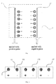
Fig. 1 is a schematic view of a structure of a corona discharge unit according to an embodiment of the present invention; -
Fig. 2 is a schematic sectional view of a structure of a plurality of corona discharge units where corona metal wires are horizontally arranged according to an embodiment of the present invention; -
Fig. 3 is a schematic sectional view of a structure of a plurality of corona discharge units where corona metal wires are arranged in two layers according to an embodiment of the present invention; -
Fig. 4 is a schematic sectional view of a structure of a plurality of corona discharge units where corona metal wires are arranged in a ring according to an embodiment of the present invention; and -
Fig. 5 is a schematic view of a structure of an ion mobility spectrometer according to an embodiment of the present invention. - These embodiments of the present invention will be described hereinafter clearly and completely with reference to the attached drawings. Obviously, the embodiments illustrated in these drawings are used to explain and illustrate the present invention, but not to limit the present invention.
- Referring to
Fig. 1 , the present invention provides a corona discharge assembly which is used in a corona source. The corona discharge assembly comprises at least onecorona discharge unit 1, thecorona discharge unit 1 comprises a pair ofcorona metal wires corona metal wires - As shown in
Fig. 1 , according to the present invention, eachcorona discharge unit 1 comprises a pair ofcorona metal wires corona metal wires corona metal wires - Working process of the corona discharge assembly according to the present invention will be presented as follows. When the
corona metal wires corona metal wires corona metal wire 11 and thecorona metal wire 12 are in a zero electric field region and are under equal potential. When thecorona metal wires corona metal wires corona metal wire 11 while a pulse having negative polarity (-) is applied on thecorona metal wire 12. Amplitudes of the pulses applied on thecorona metal wire 11 and thecorona metal wire 12 are preferably ranged from 1kV to 5kV. In this case, positive pulse corona discharge is performed at thecorona metal wire 11 while negative pulse corona discharge is performed at thecorona metal wire 12. Positive ions are produced at thecorona metal wire 11 while negative ions are produced at thecorona metal wire 12. Positive ions produced at thecorona metal wire 11 move towards thecorona metal wire 12 under a strong electric field created from the pulses applied on thecorona metal wire 11 and thecorona metal wire 12. Negative ions produced at thecorona metal wire 12 move towards thecorona metal wire 11 under a strong electric field created from the pulses applied on thecorona metal wire 11 and thecorona metal wire 12. Width of the pulse applied on thecorona metal wire 11 and thecorona metal wire 12 is preferably less than 1 microsecond. The width of the pulse applied on thecorona metal wire 11 and thecorona metal wire 12 to implement an effective discharge is short, accordingly, when the corona discharge is performed, positive ions are produced at thecorona metal wire 11 but the time is not long enough for the positive ions to arrive at thecorona metal wire 12 while negative ions are produced at thecorona metal wire 12 but the time is not long enough for the negative ions to arrive at thecorona metal wire 11. After completion of the pulses, the positive ions produced at thecorona metal wire 11 and the negative ions produced at thecorona metal wire 12 spread and react with molecules (O2, H2O, N2) in the air, in field-free space, to generate plenty of reactive ions (O2 -, (H2O)H+, NO+ and their hydrates). After sufficient charge exchange between the sample molecules M and the reactive ions in the ionization area, the produced sample ions (M(H2O)nO2 -, M(H2O)nH+ and the like, n=1, 2, 3,...) come into the drift tube, and then arrive at the Faraday disc under the action of a drift field, to achieve the object of identifying substance in accordance with different flight times. - In this present invention,
corona metal wires corona metal wires Fig. 2 to Fig. 4 , in order to prolong service life of the corona source as far as possible, a plurality ofcorona discharge units 1 are adopted in the corona source, and the corona metal wires in the plurality ofcorona discharge units 1 are arranged alternately in accordance with the polarities of the pulses applied. As shown inFig. 2 to Fig. 4 , the corona discharge assembly comprises a plurality ofcorona discharge units 1. Thecorona metal wires corona discharge units 1 are arranged in parallel, while positive and negativecorona metal wires Fig. 2 to Fig. 4 , in the present invention, the plurality ofcorona discharge units 1 adopted in the corona source may be operated alternately or simultaneously. Manners of operating the plurality ofcorona discharge units 1 adopted in the corona source will be respectively described in detail hereinafter. - A manner is that the plurality of
corona discharge units Fig. 2 to Fig. 4 , in operation, pulses are applied to only the corona metal wire 11 (-1) and the corona metal wire 12 (+1) of the firstcorona discharge unit 101, while the corona metal wires of the restcorona discharge units corona discharge unit 102, and pulses are applied to only the corona metal wire 11 (-2) and the corona metal wire 12 (+2) of the secondcorona discharge unit 102. After that, similarly, it is switched to operate the thirdcorona discharge unit 103. As a result, service life of the corona source is effectively prolonged. - Another manner is that the plurality of
corona discharge units Fig. 2 to Fig. 4 , all the positivecorona metal wires 11 of the plurality ofcorona discharge units corona metal wires 12 are electrically connected, however, corona discharge is performed only between one or several pairs of corona metal wires which have closest spacing(s) therebetween, while no corona discharge is performed between the rest of these corona metal wires. The manner of operating the plurality of corona discharge units simultaneously has the following advantages: (1) when one pair of corona metal wires or some corona metal wires do not operate, the rest of these corona metal wires begin to perform corona discharge, which effectively prolongs service life of the corona source; and, (2) corona discharge performed by multiple-corona metal wire structure will generate much more ions, thereby effectively increasing quantity of the reactive ions. - Referring to
Fig. 2 , in one implementation of the present invention, a plurality ofcorona metal wires corona discharge units corona metal wires corona metal wires - Referring to
Fig. 3 , in another implementation of the present invention, a plurality of corona metal wires of a plurality ofcorona discharge units corona metal wires corona metal wires 11 while a lower row of corona metal wires are negativecorona metal wires 12. For example, when all of the positivecorona metal wires 11 and the negativecorona metal wires 12 operate, corona discharges are performed between adjacentcorona metal wires 11, 12 ("+1" and "-1", "-2"). Corona discharges are performed alternately between the upper and lower rows ofcorona metal wires - Referring to
Fig. 4 , in yet another implementation of the present invention, cross sections of thecorona metal wires corona discharge units corona metal wires corona metal wires - It should be understood that, in the corona source shown in
Fig. 2 to Fig. 4 of the present invention, the plurality of corona discharge units may be operated alternately or simultaneously, and specific processes of the operation can refer to the above implementations and will be omitted for clarity. - In order to further present advantage of the corona discharge assembly according to the present invention, the present invention also provides an ion mobility spectrometer with the abovementioned corona discharge assembly. Referring to
Fig. 5 , the ion mobility spectrometer comprises anionization area 10, anion gate 2, a drift tube (migration area) 3 and aFaraday disc 5 arranged in sequence, acorona discharge assembly 1 is fixed in the ionization area and is the one described in the above. The ion mobility spectrometer according to the present invention will be described in detail hereinafter. - Referring to
Fig. 5 , the corona source in the ionization area comprises onecorona discharge assembly 1, and corona metal wires of thecorona discharge assembly 1 are fixed within theionization area 10, and directions of the corona metal wires preferably are perpendicular to a direction of ion drift. An electric potential of theionization area 10 is equal to a direct current offset of the corona metal wires. In the present invention, theion gate 2 may be a BN gate or a Tnydal gate (, it should be noted that the present invention is not limited to this, and any type of the gate existing in prior art can be used in the present invention). Thedrift tube 3 is formed by a series ofelectrodes 31. Anaperture grid 4 is disposed between thedrift tube 3 and theFaraday disc 5. - Referring to
Fig. 5 , operational process of the ion mobility spectrometer including the corona discharge assembly according to the present invention is described as follows. Pulses having the same amplitude but opposite polarities are respectively applied onto two corona metal wires in theionization area 10, to produce plenty of positive and negative ions between surfaces of the two corona metal wires. These positive and negative ions move towards opposite corona metal wires. Due to the short width of pulse applied, the pulse ends before plenty of positive and negative ions arrive at opposite corona metal wires and the positive and negative ions spread and react with molecules in the air within theionization area 10 to generate plenty of reactive ions. After sufficient charge exchange between the sample molecules and the reactive ions in theionization area 1, the sample ions are produced. After theion gate 2 opens, the sample ions come into thedrift tube 3, and then arrive at theFaraday disc 5 through theaperture grid 4 under the action of an electric field. The corona metal wires can generate more reactive ions than corona needles or tips, facilitating improving sensitivity of the ion mobility spectrometer. When the corona metal wire is covered with an oxide layer by contamination of impurities and samples, the oxide layer may be eliminated through electrifying the corona metal wire to prolong service life of the corona metal wire. - In order to further present advantage of the corona discharge assembly according to the present invention, the present invention also provides a corona discharge method being implemented on the abovementioned corona discharge assembly. This method comprises the following steps of: applying pulses having the same amplitude but opposite polarities onto the corona metal wires. When the corona metal wire is covered with an oxide layer by contamination of impurities and samples (mainly a variety of organic matters), the oxide layer may be eliminated through electrifying the corona metal wire. When the corona metal wire is electrified and thus heated, these matters will be eliminated by volatilization or oxidation, prolong service life of the corona metal wire.
- Concerning the above, the corona discharge assembly, the ion mobility spectrometer and the corona discharge method according to the present invention can generate more reactive ions than corona needles or tips, facilitate improving sensitivity of the ion mobility spectrometer, and effectively prolong service life of a corona source to 3-10 years.
Claims (14)
- A corona discharge assembly characterized by comprising at least one corona discharge unit, wherein, the corona discharge unit comprises a pair of corona metal wires arranged in parallel, and pulses having the same amplitude but opposite polarities are respectively applied to the corona metal wires arranged in parallel.
- The corona discharge assembly of claim 1, characterized in that, the corona metal wires have a diameter ranged from 10 micrometers to 50 micrometers.
- The corona discharge assembly of claim 1, characterized in that, the corona metal wires are made of platinum or palladium.
- The corona discharge assembly of claim 1, characterized in that, an amplitude of the pulses is ranged from 1 kV to 5 kV.
- The corona discharge assembly of claim 1, characterized in that, a width of the pulses is less than 1 microsecond.
- The corona discharge assembly of claim 1, characterized in that, the at least one corona discharge unit comprises a plurality of corona discharge units;
corona metal wires of the plurality of corona discharge units are arranged alternately in accordance with the polarities of the pulses applied. - The corona discharge assembly of claim 6, characterized in that, the corona metal wires of the corona discharge units are arranged linearly.
- The corona discharge assembly of claim 6, characterized in that, the corona metal wires of the corona discharge units are arranged in a zigzag array manner.
- The corona discharge assembly of claim 6, characterized in that, the corona metal wires of the corona discharge units are arranged in a ring array.
- An ion mobility spectrometer characterized by comprising an ionization area, an ion gate, a drift tube and a Faraday disc arranged in sequence, a corona discharge assembly of any one of claims 1-9 being fixed in the ionization area.
- The ion mobility spectrometer of claim 10, characterized in that, an electric potential of the ionization area is equal to a direct current offset of the corona metal wires.
- The ion mobility spectrometer of claim 10, characterized in that, a direction of the corona metal wire is perpendicular to an axial direction of an ion drift tube.
- A corona discharge method characterized by being implemented on a corona discharge assembly of any one of claims 1-9 and comprising the following steps of:applying pulses having the same amplitude but opposite polarities onto the corona metal wires.
- The corona discharge method of claim 13 characterized by further comprising a step of electrically energizing the corona metal wires to remove an oxide layer.
Priority Applications (1)
| Application Number | Priority Date | Filing Date | Title |
|---|---|---|---|
| PL16191655T PL3187868T3 (en) | 2015-12-31 | 2016-09-30 | Corona discharge assembly, ion mobility spectrometer and corona discharge method |
Applications Claiming Priority (1)
| Application Number | Priority Date | Filing Date | Title |
|---|---|---|---|
| CN201511032539.6A CN105655228B (en) | 2015-12-31 | 2015-12-31 | A corona discharge assembly, ion mobility spectrometer and corona discharge method |
Publications (2)
| Publication Number | Publication Date |
|---|---|
| EP3187868A1 true EP3187868A1 (en) | 2017-07-05 |
| EP3187868B1 EP3187868B1 (en) | 2018-11-14 |
Family
ID=56490236
Family Applications (1)
| Application Number | Title | Priority Date | Filing Date |
|---|---|---|---|
| EP16191655.6A Active EP3187868B1 (en) | 2015-12-31 | 2016-09-30 | Corona discharge assembly, ion mobility spectrometer and corona discharge method |
Country Status (7)
| Country | Link |
|---|---|
| US (1) | US10317365B2 (en) |
| EP (1) | EP3187868B1 (en) |
| JP (1) | JP6488026B2 (en) |
| CN (1) | CN105655228B (en) |
| PL (1) | PL3187868T3 (en) |
| RU (1) | RU2691980C2 (en) |
| WO (1) | WO2017113804A1 (en) |
Cited By (1)
| Publication number | Priority date | Publication date | Assignee | Title |
|---|---|---|---|---|
| CN114169188A (en) * | 2021-11-16 | 2022-03-11 | 西安理工大学 | Negative-polarity corona discharge continuity current pulse simulation method |
Families Citing this family (2)
| Publication number | Priority date | Publication date | Assignee | Title |
|---|---|---|---|---|
| CN105655228B (en) * | 2015-12-31 | 2017-07-28 | 同方威视技术股份有限公司 | A corona discharge assembly, ion mobility spectrometer and corona discharge method |
| CN114203519B (en) * | 2021-12-17 | 2022-09-23 | 中船重工安谱(湖北)仪器有限公司 | Discharge device and ion mobility spectrometer |
Citations (5)
| Publication number | Priority date | Publication date | Assignee | Title |
|---|---|---|---|---|
| US20040164238A1 (en) * | 2002-09-25 | 2004-08-26 | Jun Xu | Pulsed discharge ionization source for miniature ion mobility spectrometers |
| WO2006107390A2 (en) * | 2005-04-04 | 2006-10-12 | Kronos Advanced Technologies, Inc. | An electrostatic fluid accelerator for and method of controlling a fluid flow |
| GB2465166A (en) * | 2008-11-06 | 2010-05-12 | Brixs Ltd | Security apparatus comprising an ion mobility spectrometer |
| US20120200982A1 (en) * | 2011-02-08 | 2012-08-09 | Illinois Tool Works Inc. | Micropulse bipolar corona ionizer and method |
| US20150250044A1 (en) * | 2014-02-28 | 2015-09-03 | Illinois Tool Works Inc. | Linear ionizing bar with configurable nozzles |
Family Cites Families (17)
| Publication number | Priority date | Publication date | Assignee | Title |
|---|---|---|---|---|
| GB1597622A (en) * | 1977-03-11 | 1981-09-09 | Lovelock J E | Solute switching systems incorporating corona discharge devices |
| JPS59189649U (en) * | 1983-06-03 | 1984-12-15 | 株式会社リコー | corona charger |
| GB2319201B (en) * | 1996-11-09 | 2001-05-23 | Xerox Corp | Method of manufacture of corotron wire assembly |
| JPH10255954A (en) * | 1997-03-11 | 1998-09-25 | Aibitsuku Kogyo Kk | DC ion generator and coating film forming method using the same |
| US7157704B2 (en) * | 2003-12-02 | 2007-01-02 | Kronos Advanced Technologies, Inc. | Corona discharge electrode and method of operating the same |
| EP1971855B1 (en) * | 2006-01-10 | 2018-05-02 | Smiths Detection-Watford Limited | Ion selection apparatus and method |
| CN106885838B (en) * | 2007-02-05 | 2021-01-12 | 卓漂仪谱公司 | Ion mobility spectrometer and method |
| GB0707254D0 (en) * | 2007-04-14 | 2007-05-23 | Smiths Detection Watford Ltd | Detectors and ion sources |
| JP5097514B2 (en) * | 2007-11-22 | 2012-12-12 | 国立大学法人東京工業大学 | Wire electrode ionizer |
| CN101738429B (en) * | 2008-11-26 | 2013-04-03 | 岛津分析技术研发(上海)有限公司 | Ion separation, enrichment and detection device |
| EP2237307B1 (en) * | 2009-03-30 | 2014-05-14 | Vidal de Miguel, Guillermo | Method and apparatus to produce steady beams of mobility selected ions via time-dependent electric fields |
| CN102479659A (en) * | 2010-11-30 | 2012-05-30 | 中国科学院大连化学物理研究所 | An ionization source and its application in aerosol detection |
| CN103137417B (en) * | 2011-12-02 | 2016-01-06 | 同方威视技术股份有限公司 | Corona discharge assembly and there is the ionic migration spectrometer of this corona discharge assembly |
| KR102220784B1 (en) * | 2013-03-18 | 2021-02-25 | 스미스 디텍션 몬트리올 인코포레이티드 | Ion mobility spectrometry (ims) device with charged material transportation chamber |
| US8907275B1 (en) * | 2013-05-20 | 2014-12-09 | Sociedad Europea de Analisis Diferencial de Movilidad | Method and apparatus to improve the separation capacity in a sequence of ion filters incorporating at least two ion mobility analyzers |
| CN105655228B (en) * | 2015-12-31 | 2017-07-28 | 同方威视技术股份有限公司 | A corona discharge assembly, ion mobility spectrometer and corona discharge method |
| CN205428870U (en) * | 2015-12-31 | 2016-08-03 | 同方威视技术股份有限公司 | Corona discharge subassembly and ion mobility spectrometer |
-
2015
- 2015-12-31 CN CN201511032539.6A patent/CN105655228B/en active Active
-
2016
- 2016-08-09 RU RU2017140862A patent/RU2691980C2/en not_active IP Right Cessation
- 2016-08-09 JP JP2017563514A patent/JP6488026B2/en active Active
- 2016-08-09 WO PCT/CN2016/094164 patent/WO2017113804A1/en not_active Ceased
- 2016-08-09 US US15/578,536 patent/US10317365B2/en active Active
- 2016-09-30 EP EP16191655.6A patent/EP3187868B1/en active Active
- 2016-09-30 PL PL16191655T patent/PL3187868T3/en unknown
Patent Citations (5)
| Publication number | Priority date | Publication date | Assignee | Title |
|---|---|---|---|---|
| US20040164238A1 (en) * | 2002-09-25 | 2004-08-26 | Jun Xu | Pulsed discharge ionization source for miniature ion mobility spectrometers |
| WO2006107390A2 (en) * | 2005-04-04 | 2006-10-12 | Kronos Advanced Technologies, Inc. | An electrostatic fluid accelerator for and method of controlling a fluid flow |
| GB2465166A (en) * | 2008-11-06 | 2010-05-12 | Brixs Ltd | Security apparatus comprising an ion mobility spectrometer |
| US20120200982A1 (en) * | 2011-02-08 | 2012-08-09 | Illinois Tool Works Inc. | Micropulse bipolar corona ionizer and method |
| US20150250044A1 (en) * | 2014-02-28 | 2015-09-03 | Illinois Tool Works Inc. | Linear ionizing bar with configurable nozzles |
Non-Patent Citations (1)
| Title |
|---|
| J-C MATÃ CR O-VÃ CR LEZ ET AL: "Modelling wire-to-wire corona discharge action on aerodynamics and comparison with experiment; Wire-to-wire corona discharge action aerodynamics", JOURNAL OF PHYSICS D: APPLIED PHYSICS, INSTITUTE OF PHYSICS PUBLISHING LTD, GB, vol. 41, no. 3, 7 February 2008 (2008-02-07), pages 35205, XP020126998, ISSN: 0022-3727 * |
Cited By (1)
| Publication number | Priority date | Publication date | Assignee | Title |
|---|---|---|---|---|
| CN114169188A (en) * | 2021-11-16 | 2022-03-11 | 西安理工大学 | Negative-polarity corona discharge continuity current pulse simulation method |
Also Published As
| Publication number | Publication date |
|---|---|
| CN105655228B (en) | 2017-07-28 |
| EP3187868B1 (en) | 2018-11-14 |
| RU2017140862A3 (en) | 2019-05-23 |
| JP2018518811A (en) | 2018-07-12 |
| RU2017140862A (en) | 2019-05-23 |
| RU2691980C2 (en) | 2019-06-19 |
| JP6488026B2 (en) | 2019-03-20 |
| WO2017113804A1 (en) | 2017-07-06 |
| PL3187868T3 (en) | 2019-04-30 |
| CN105655228A (en) | 2016-06-08 |
| US20180292353A1 (en) | 2018-10-11 |
| US10317365B2 (en) | 2019-06-11 |
Similar Documents
| Publication | Publication Date | Title |
|---|---|---|
| RU2737111C1 (en) | Bipolar ioniser for air cleaning and diffuser for bipolar ioniser | |
| EP0253155A1 (en) | Electric field control in ion mobility spectrometry | |
| US20160215974A1 (en) | Ionizer for a combustion system | |
| US10317365B2 (en) | Corona discharge assembly, ion mobility spectrometer and corona discharge method | |
| JP2005174619A (en) | Ion mobility spectrometer and ion mobility spectroscopy | |
| EP3637454B1 (en) | Ion migration rate analysis device and analysis method applied | |
| US4831254A (en) | Ion drift detector | |
| Liu et al. | Development processes of positive and negative DC corona under needle-plate electrode in air | |
| WO2004114347A3 (en) | Single device for ion mobility and ion trap mass spectrometry | |
| EP3014648B1 (en) | Dual polarity spark ion source | |
| JP5989105B2 (en) | Loop shape ionization source | |
| CN105814440A (en) | Dielectric barrier discharge ionization source for spectrometry | |
| KR20170066463A (en) | Duel mode ion mobility spectrometer | |
| CN109659219B (en) | Ion gate device without ion discrimination and control method | |
| CN107941897B (en) | Bipolar controllable pulse corona discharge ionization source and ion mobility spectrometer thereof | |
| CN102479659A (en) | An ionization source and its application in aerosol detection | |
| CN105632874A (en) | DC non-uniform electric field ion migration tube | |
| CN205428870U (en) | Corona discharge subassembly and ion mobility spectrometer | |
| CN103779169A (en) | Surface discharge ionization source ion gate-free transference tube | |
| JP4304342B2 (en) | Atmospheric pressure corona discharge generator | |
| CN105023824A (en) | Ion gate and preparation method therefor | |
| CA2860077A1 (en) | Asymmetric field ion mobility spectrometer | |
| DE102012016583B4 (en) | Ion mobility spectrometer for detecting analytes | |
| Diguang et al. | Analysis of the current for a negative point-to-plane corona discharge in air | |
| CN112951699B (en) | Separation method of ion mobility spectrometry overlapping peaks |
Legal Events
| Date | Code | Title | Description |
|---|---|---|---|
| PUAI | Public reference made under article 153(3) epc to a published international application that has entered the european phase |
Free format text: ORIGINAL CODE: 0009012 |
|
| STAA | Information on the status of an ep patent application or granted ep patent |
Free format text: STATUS: THE APPLICATION HAS BEEN PUBLISHED |
|
| AK | Designated contracting states |
Kind code of ref document: A1 Designated state(s): AL AT BE BG CH CY CZ DE DK EE ES FI FR GB GR HR HU IE IS IT LI LT LU LV MC MK MT NL NO PL PT RO RS SE SI SK SM TR |
|
| AX | Request for extension of the european patent |
Extension state: BA ME |
|
| STAA | Information on the status of an ep patent application or granted ep patent |
Free format text: STATUS: REQUEST FOR EXAMINATION WAS MADE |
|
| 17P | Request for examination filed |
Effective date: 20171221 |
|
| RBV | Designated contracting states (corrected) |
Designated state(s): AL AT BE BG CH CY CZ DE DK EE ES FI FR GB GR HR HU IE IS IT LI LT LU LV MC MK MT NL NO PL PT RO RS SE SI SK SM TR |
|
| REG | Reference to a national code |
Ref country code: DE Ref legal event code: R079 Ref document number: 602016007150 Country of ref document: DE Free format text: PREVIOUS MAIN CLASS: G01N0027620000 Ipc: H01J0027260000 |
|
| RIC1 | Information provided on ipc code assigned before grant |
Ipc: G01N 27/62 20060101ALI20180326BHEP Ipc: G01N 27/68 20060101ALI20180326BHEP Ipc: H01J 27/02 20060101AFI20180326BHEP |
|
| GRAP | Despatch of communication of intention to grant a patent |
Free format text: ORIGINAL CODE: EPIDOSNIGR1 |
|
| STAA | Information on the status of an ep patent application or granted ep patent |
Free format text: STATUS: GRANT OF PATENT IS INTENDED |
|
| RIC1 | Information provided on ipc code assigned before grant |
Ipc: G01N 27/62 20060101ALI20180406BHEP Ipc: H01J 27/26 20060101AFI20180406BHEP Ipc: G01N 27/68 20060101ALI20180406BHEP |
|
| INTG | Intention to grant announced |
Effective date: 20180507 |
|
| GRAS | Grant fee paid |
Free format text: ORIGINAL CODE: EPIDOSNIGR3 |
|
| GRAA | (expected) grant |
Free format text: ORIGINAL CODE: 0009210 |
|
| STAA | Information on the status of an ep patent application or granted ep patent |
Free format text: STATUS: THE PATENT HAS BEEN GRANTED |
|
| AK | Designated contracting states |
Kind code of ref document: B1 Designated state(s): AL AT BE BG CH CY CZ DE DK EE ES FI FR GB GR HR HU IE IS IT LI LT LU LV MC MK MT NL NO PL PT RO RS SE SI SK SM TR |
|
| REG | Reference to a national code |
Ref country code: CH Ref legal event code: EP Ref country code: AT Ref legal event code: REF Ref document number: 1065841 Country of ref document: AT Kind code of ref document: T Effective date: 20181115 |
|
| REG | Reference to a national code |
Ref country code: DE Ref legal event code: R096 Ref document number: 602016007150 Country of ref document: DE |
|
| REG | Reference to a national code |
Ref country code: IE Ref legal event code: FG4D |
|
| REG | Reference to a national code |
Ref country code: NL Ref legal event code: FP |
|
| REG | Reference to a national code |
Ref country code: LT Ref legal event code: MG4D |
|
| REG | Reference to a national code |
Ref country code: AT Ref legal event code: MK05 Ref document number: 1065841 Country of ref document: AT Kind code of ref document: T Effective date: 20181114 |
|
| PG25 | Lapsed in a contracting state [announced via postgrant information from national office to epo] |
Ref country code: IS Free format text: LAPSE BECAUSE OF FAILURE TO SUBMIT A TRANSLATION OF THE DESCRIPTION OR TO PAY THE FEE WITHIN THE PRESCRIBED TIME-LIMIT Effective date: 20190314 Ref country code: BG Free format text: LAPSE BECAUSE OF FAILURE TO SUBMIT A TRANSLATION OF THE DESCRIPTION OR TO PAY THE FEE WITHIN THE PRESCRIBED TIME-LIMIT Effective date: 20190214 Ref country code: LT Free format text: LAPSE BECAUSE OF FAILURE TO SUBMIT A TRANSLATION OF THE DESCRIPTION OR TO PAY THE FEE WITHIN THE PRESCRIBED TIME-LIMIT Effective date: 20181114 Ref country code: FI Free format text: LAPSE BECAUSE OF FAILURE TO SUBMIT A TRANSLATION OF THE DESCRIPTION OR TO PAY THE FEE WITHIN THE PRESCRIBED TIME-LIMIT Effective date: 20181114 Ref country code: NO Free format text: LAPSE BECAUSE OF FAILURE TO SUBMIT A TRANSLATION OF THE DESCRIPTION OR TO PAY THE FEE WITHIN THE PRESCRIBED TIME-LIMIT Effective date: 20190214 Ref country code: AT Free format text: LAPSE BECAUSE OF FAILURE TO SUBMIT A TRANSLATION OF THE DESCRIPTION OR TO PAY THE FEE WITHIN THE PRESCRIBED TIME-LIMIT Effective date: 20181114 Ref country code: ES Free format text: LAPSE BECAUSE OF FAILURE TO SUBMIT A TRANSLATION OF THE DESCRIPTION OR TO PAY THE FEE WITHIN THE PRESCRIBED TIME-LIMIT Effective date: 20181114 Ref country code: LV Free format text: LAPSE BECAUSE OF FAILURE TO SUBMIT A TRANSLATION OF THE DESCRIPTION OR TO PAY THE FEE WITHIN THE PRESCRIBED TIME-LIMIT Effective date: 20181114 Ref country code: HR Free format text: LAPSE BECAUSE OF FAILURE TO SUBMIT A TRANSLATION OF THE DESCRIPTION OR TO PAY THE FEE WITHIN THE PRESCRIBED TIME-LIMIT Effective date: 20181114 |
|
| PG25 | Lapsed in a contracting state [announced via postgrant information from national office to epo] |
Ref country code: PT Free format text: LAPSE BECAUSE OF FAILURE TO SUBMIT A TRANSLATION OF THE DESCRIPTION OR TO PAY THE FEE WITHIN THE PRESCRIBED TIME-LIMIT Effective date: 20190314 Ref country code: AL Free format text: LAPSE BECAUSE OF FAILURE TO SUBMIT A TRANSLATION OF THE DESCRIPTION OR TO PAY THE FEE WITHIN THE PRESCRIBED TIME-LIMIT Effective date: 20181114 Ref country code: SE Free format text: LAPSE BECAUSE OF FAILURE TO SUBMIT A TRANSLATION OF THE DESCRIPTION OR TO PAY THE FEE WITHIN THE PRESCRIBED TIME-LIMIT Effective date: 20181114 Ref country code: RS Free format text: LAPSE BECAUSE OF FAILURE TO SUBMIT A TRANSLATION OF THE DESCRIPTION OR TO PAY THE FEE WITHIN THE PRESCRIBED TIME-LIMIT Effective date: 20181114 Ref country code: GR Free format text: LAPSE BECAUSE OF FAILURE TO SUBMIT A TRANSLATION OF THE DESCRIPTION OR TO PAY THE FEE WITHIN THE PRESCRIBED TIME-LIMIT Effective date: 20190215 |
|
| PG25 | Lapsed in a contracting state [announced via postgrant information from national office to epo] |
Ref country code: CZ Free format text: LAPSE BECAUSE OF FAILURE TO SUBMIT A TRANSLATION OF THE DESCRIPTION OR TO PAY THE FEE WITHIN THE PRESCRIBED TIME-LIMIT Effective date: 20181114 Ref country code: DK Free format text: LAPSE BECAUSE OF FAILURE TO SUBMIT A TRANSLATION OF THE DESCRIPTION OR TO PAY THE FEE WITHIN THE PRESCRIBED TIME-LIMIT Effective date: 20181114 Ref country code: IT Free format text: LAPSE BECAUSE OF FAILURE TO SUBMIT A TRANSLATION OF THE DESCRIPTION OR TO PAY THE FEE WITHIN THE PRESCRIBED TIME-LIMIT Effective date: 20181114 |
|
| REG | Reference to a national code |
Ref country code: DE Ref legal event code: R097 Ref document number: 602016007150 Country of ref document: DE |
|
| PG25 | Lapsed in a contracting state [announced via postgrant information from national office to epo] |
Ref country code: EE Free format text: LAPSE BECAUSE OF FAILURE TO SUBMIT A TRANSLATION OF THE DESCRIPTION OR TO PAY THE FEE WITHIN THE PRESCRIBED TIME-LIMIT Effective date: 20181114 Ref country code: SM Free format text: LAPSE BECAUSE OF FAILURE TO SUBMIT A TRANSLATION OF THE DESCRIPTION OR TO PAY THE FEE WITHIN THE PRESCRIBED TIME-LIMIT Effective date: 20181114 Ref country code: SK Free format text: LAPSE BECAUSE OF FAILURE TO SUBMIT A TRANSLATION OF THE DESCRIPTION OR TO PAY THE FEE WITHIN THE PRESCRIBED TIME-LIMIT Effective date: 20181114 Ref country code: RO Free format text: LAPSE BECAUSE OF FAILURE TO SUBMIT A TRANSLATION OF THE DESCRIPTION OR TO PAY THE FEE WITHIN THE PRESCRIBED TIME-LIMIT Effective date: 20181114 |
|
| PLBE | No opposition filed within time limit |
Free format text: ORIGINAL CODE: 0009261 |
|
| STAA | Information on the status of an ep patent application or granted ep patent |
Free format text: STATUS: NO OPPOSITION FILED WITHIN TIME LIMIT |
|
| 26N | No opposition filed |
Effective date: 20190815 |
|
| PG25 | Lapsed in a contracting state [announced via postgrant information from national office to epo] |
Ref country code: SI Free format text: LAPSE BECAUSE OF FAILURE TO SUBMIT A TRANSLATION OF THE DESCRIPTION OR TO PAY THE FEE WITHIN THE PRESCRIBED TIME-LIMIT Effective date: 20181114 |
|
| PG25 | Lapsed in a contracting state [announced via postgrant information from national office to epo] |
Ref country code: TR Free format text: LAPSE BECAUSE OF FAILURE TO SUBMIT A TRANSLATION OF THE DESCRIPTION OR TO PAY THE FEE WITHIN THE PRESCRIBED TIME-LIMIT Effective date: 20181114 |
|
| PG25 | Lapsed in a contracting state [announced via postgrant information from national office to epo] |
Ref country code: MC Free format text: LAPSE BECAUSE OF FAILURE TO SUBMIT A TRANSLATION OF THE DESCRIPTION OR TO PAY THE FEE WITHIN THE PRESCRIBED TIME-LIMIT Effective date: 20181114 |
|
| REG | Reference to a national code |
Ref country code: CH Ref legal event code: PL |
|
| PG25 | Lapsed in a contracting state [announced via postgrant information from national office to epo] |
Ref country code: CH Free format text: LAPSE BECAUSE OF NON-PAYMENT OF DUE FEES Effective date: 20190930 Ref country code: LU Free format text: LAPSE BECAUSE OF NON-PAYMENT OF DUE FEES Effective date: 20190930 Ref country code: IE Free format text: LAPSE BECAUSE OF NON-PAYMENT OF DUE FEES Effective date: 20190930 Ref country code: LI Free format text: LAPSE BECAUSE OF NON-PAYMENT OF DUE FEES Effective date: 20190930 |
|
| REG | Reference to a national code |
Ref country code: BE Ref legal event code: MM Effective date: 20190930 |
|
| PG25 | Lapsed in a contracting state [announced via postgrant information from national office to epo] |
Ref country code: BE Free format text: LAPSE BECAUSE OF NON-PAYMENT OF DUE FEES Effective date: 20190930 |
|
| PG25 | Lapsed in a contracting state [announced via postgrant information from national office to epo] |
Ref country code: CY Free format text: LAPSE BECAUSE OF FAILURE TO SUBMIT A TRANSLATION OF THE DESCRIPTION OR TO PAY THE FEE WITHIN THE PRESCRIBED TIME-LIMIT Effective date: 20181114 |
|
| PG25 | Lapsed in a contracting state [announced via postgrant information from national office to epo] |
Ref country code: MT Free format text: LAPSE BECAUSE OF FAILURE TO SUBMIT A TRANSLATION OF THE DESCRIPTION OR TO PAY THE FEE WITHIN THE PRESCRIBED TIME-LIMIT Effective date: 20181114 Ref country code: HU Free format text: LAPSE BECAUSE OF FAILURE TO SUBMIT A TRANSLATION OF THE DESCRIPTION OR TO PAY THE FEE WITHIN THE PRESCRIBED TIME-LIMIT; INVALID AB INITIO Effective date: 20160930 |
|
| PG25 | Lapsed in a contracting state [announced via postgrant information from national office to epo] |
Ref country code: MK Free format text: LAPSE BECAUSE OF FAILURE TO SUBMIT A TRANSLATION OF THE DESCRIPTION OR TO PAY THE FEE WITHIN THE PRESCRIBED TIME-LIMIT Effective date: 20181114 |
|
| P01 | Opt-out of the competence of the unified patent court (upc) registered |
Effective date: 20230528 |
|
| PGFP | Annual fee paid to national office [announced via postgrant information from national office to epo] |
Ref country code: NL Payment date: 20250724 Year of fee payment: 10 |
|
| PGFP | Annual fee paid to national office [announced via postgrant information from national office to epo] |
Ref country code: DE Payment date: 20250919 Year of fee payment: 10 |
|
| PGFP | Annual fee paid to national office [announced via postgrant information from national office to epo] |
Ref country code: PL Payment date: 20250919 Year of fee payment: 10 |
|
| PGFP | Annual fee paid to national office [announced via postgrant information from national office to epo] |
Ref country code: GB Payment date: 20250804 Year of fee payment: 10 |
|
| PGFP | Annual fee paid to national office [announced via postgrant information from national office to epo] |
Ref country code: FR Payment date: 20250722 Year of fee payment: 10 |