EP3187803A1 - Easy open drawer/door with a rotating handle - Google Patents
Easy open drawer/door with a rotating handle Download PDFInfo
- Publication number
- EP3187803A1 EP3187803A1 EP16204554.6A EP16204554A EP3187803A1 EP 3187803 A1 EP3187803 A1 EP 3187803A1 EP 16204554 A EP16204554 A EP 16204554A EP 3187803 A1 EP3187803 A1 EP 3187803A1
- Authority
- EP
- European Patent Office
- Prior art keywords
- handle
- refrigerator
- door
- coupled
- actuator
- Prior art date
- Legal status (The legal status is an assumption and is not a legal conclusion. Google has not performed a legal analysis and makes no representation as to the accuracy of the status listed.)
- Withdrawn
Links
- 230000007246 mechanism Effects 0.000 claims abstract description 91
- 230000008878 coupling Effects 0.000 claims description 19
- 238000010168 coupling process Methods 0.000 claims description 19
- 238000005859 coupling reaction Methods 0.000 claims description 19
- 238000000034 method Methods 0.000 description 21
- 239000006260 foam Substances 0.000 description 9
- 238000013459 approach Methods 0.000 description 7
- 239000000463 material Substances 0.000 description 7
- 230000008569 process Effects 0.000 description 5
- 238000012546 transfer Methods 0.000 description 5
- 238000013461 design Methods 0.000 description 4
- 238000012986 modification Methods 0.000 description 4
- 230000004048 modification Effects 0.000 description 4
- 238000010276 construction Methods 0.000 description 3
- 239000003086 colorant Substances 0.000 description 2
- 235000013305 food Nutrition 0.000 description 2
- 239000000203 mixture Substances 0.000 description 2
- 230000000712 assembly Effects 0.000 description 1
- 238000000429 assembly Methods 0.000 description 1
- 230000008859 change Effects 0.000 description 1
- 238000001816 cooling Methods 0.000 description 1
- 238000005259 measurement Methods 0.000 description 1
- 238000004321 preservation Methods 0.000 description 1
- 238000012552 review Methods 0.000 description 1
- 238000006467 substitution reaction Methods 0.000 description 1
- 229920001169 thermoplastic Polymers 0.000 description 1
- 229920001187 thermosetting polymer Polymers 0.000 description 1
- 239000004416 thermosoftening plastic Substances 0.000 description 1
- XLYOFNOQVPJJNP-UHFFFAOYSA-N water Substances O XLYOFNOQVPJJNP-UHFFFAOYSA-N 0.000 description 1
Images









Classifications
-
- F—MECHANICAL ENGINEERING; LIGHTING; HEATING; WEAPONS; BLASTING
- F25—REFRIGERATION OR COOLING; COMBINED HEATING AND REFRIGERATION SYSTEMS; HEAT PUMP SYSTEMS; MANUFACTURE OR STORAGE OF ICE; LIQUEFACTION SOLIDIFICATION OF GASES
- F25D—REFRIGERATORS; COLD ROOMS; ICE-BOXES; COOLING OR FREEZING APPARATUS NOT OTHERWISE PROVIDED FOR
- F25D23/00—General constructional features
- F25D23/02—Doors; Covers
- F25D23/028—Details
-
- E—FIXED CONSTRUCTIONS
- E05—LOCKS; KEYS; WINDOW OR DOOR FITTINGS; SAFES
- E05B—LOCKS; ACCESSORIES THEREFOR; HANDCUFFS
- E05B17/00—Accessories in connection with locks
- E05B17/0025—Devices for forcing the wing firmly against its seat or to initiate the opening of the wing
- E05B17/0033—Devices for forcing the wing firmly against its seat or to initiate the opening of the wing for opening only
-
- E—FIXED CONSTRUCTIONS
- E05—LOCKS; KEYS; WINDOW OR DOOR FITTINGS; SAFES
- E05B—LOCKS; ACCESSORIES THEREFOR; HANDCUFFS
- E05B53/00—Operation or control of locks by mechanical transmissions, e.g. from a distance
- E05B53/003—Operation or control of locks by mechanical transmissions, e.g. from a distance flexible
- E05B53/005—Bowden
-
- E—FIXED CONSTRUCTIONS
- E05—LOCKS; KEYS; WINDOW OR DOOR FITTINGS; SAFES
- E05B—LOCKS; ACCESSORIES THEREFOR; HANDCUFFS
- E05B7/00—Handles pivoted about an axis parallel to the wing
-
- E—FIXED CONSTRUCTIONS
- E05—LOCKS; KEYS; WINDOW OR DOOR FITTINGS; SAFES
- E05F—DEVICES FOR MOVING WINGS INTO OPEN OR CLOSED POSITION; CHECKS FOR WINGS; WING FITTINGS NOT OTHERWISE PROVIDED FOR, CONCERNED WITH THE FUNCTIONING OF THE WING
- E05F11/00—Man-operated mechanisms for operating wings, including those which also operate the fastening
- E05F11/02—Man-operated mechanisms for operating wings, including those which also operate the fastening for wings in general, e.g. fanlights
- E05F11/08—Man-operated mechanisms for operating wings, including those which also operate the fastening for wings in general, e.g. fanlights with longitudinally-moving bars guided, e.g. by pivoted links, in or on the frame
- E05F11/12—Mechanisms by which the bar shifts the wing
- E05F11/16—Mechanisms by which the bar shifts the wing shifting the wing by pivotally-connected members (moving) in a plane perpendicular to the pivot axis of the wing
-
- F—MECHANICAL ENGINEERING; LIGHTING; HEATING; WEAPONS; BLASTING
- F25—REFRIGERATION OR COOLING; COMBINED HEATING AND REFRIGERATION SYSTEMS; HEAT PUMP SYSTEMS; MANUFACTURE OR STORAGE OF ICE; LIQUEFACTION SOLIDIFICATION OF GASES
- F25D—REFRIGERATORS; COLD ROOMS; ICE-BOXES; COOLING OR FREEZING APPARATUS NOT OTHERWISE PROVIDED FOR
- F25D23/00—General constructional features
- F25D23/02—Doors; Covers
- F25D23/021—Sliding doors
-
- F—MECHANICAL ENGINEERING; LIGHTING; HEATING; WEAPONS; BLASTING
- F25—REFRIGERATION OR COOLING; COMBINED HEATING AND REFRIGERATION SYSTEMS; HEAT PUMP SYSTEMS; MANUFACTURE OR STORAGE OF ICE; LIQUEFACTION SOLIDIFICATION OF GASES
- F25D—REFRIGERATORS; COLD ROOMS; ICE-BOXES; COOLING OR FREEZING APPARATUS NOT OTHERWISE PROVIDED FOR
- F25D25/00—Charging, supporting, and discharging the articles to be cooled
- F25D25/02—Charging, supporting, and discharging the articles to be cooled by shelves
- F25D25/024—Slidable shelves
- F25D25/025—Drawers
-
- E—FIXED CONSTRUCTIONS
- E05—LOCKS; KEYS; WINDOW OR DOOR FITTINGS; SAFES
- E05Y—INDEXING SCHEME ASSOCIATED WITH SUBCLASSES E05D AND E05F, RELATING TO CONSTRUCTION ELEMENTS, ELECTRIC CONTROL, POWER SUPPLY, POWER SIGNAL OR TRANSMISSION, USER INTERFACES, MOUNTING OR COUPLING, DETAILS, ACCESSORIES, AUXILIARY OPERATIONS NOT OTHERWISE PROVIDED FOR, APPLICATION THEREOF
- E05Y2201/00—Constructional elements; Accessories therefor
- E05Y2201/60—Suspension or transmission members; Accessories therefor
- E05Y2201/622—Suspension or transmission members elements
- E05Y2201/676—Transmission of human force
- E05Y2201/68—Handles, cranks
-
- E—FIXED CONSTRUCTIONS
- E05—LOCKS; KEYS; WINDOW OR DOOR FITTINGS; SAFES
- E05Y—INDEXING SCHEME ASSOCIATED WITH SUBCLASSES E05D AND E05F, RELATING TO CONSTRUCTION ELEMENTS, ELECTRIC CONTROL, POWER SUPPLY, POWER SIGNAL OR TRANSMISSION, USER INTERFACES, MOUNTING OR COUPLING, DETAILS, ACCESSORIES, AUXILIARY OPERATIONS NOT OTHERWISE PROVIDED FOR, APPLICATION THEREOF
- E05Y2900/00—Application of doors, windows, wings or fittings thereof
- E05Y2900/30—Application of doors, windows, wings or fittings thereof for domestic appliances
- E05Y2900/31—Application of doors, windows, wings or fittings thereof for domestic appliances for refrigerators
-
- F—MECHANICAL ENGINEERING; LIGHTING; HEATING; WEAPONS; BLASTING
- F25—REFRIGERATION OR COOLING; COMBINED HEATING AND REFRIGERATION SYSTEMS; HEAT PUMP SYSTEMS; MANUFACTURE OR STORAGE OF ICE; LIQUEFACTION SOLIDIFICATION OF GASES
- F25D—REFRIGERATORS; COLD ROOMS; ICE-BOXES; COOLING OR FREEZING APPARATUS NOT OTHERWISE PROVIDED FOR
- F25D11/00—Self-contained movable devices, e.g. domestic refrigerators
- F25D11/02—Self-contained movable devices, e.g. domestic refrigerators with cooling compartments at different temperatures
Definitions
- the present disclosure relates to a refrigerator, and in particular, to a refrigerator that uses a handle to activate a pushing device installed on a drawer or door of a refrigerator by using a mechanism to transfer movement from the handle to the pushing device to separate the door from the refrigerator main body.
- a refrigerator is an apparatus for storing foods or other materials at low temperatures to preserve the food or material in a refrigerated or frozen state according to the type and condition of desired preservation.
- various types of doors for opening and closing the cabinet space are used. These doors typically have a graspable handle installed to allow a user to more easily open and close the door by grasping the door handle and pivoting the door to selectively open and close the cabinet space.
- a refrigerator includes a refrigerator body having an interior storage space, a door coupled to the refrigerator body to open and close the interior storage space, a door handle coupled to the door in a pivotally rotatable manner, and an opening actuator coupled to the door handle wherein the opening actuator applies a force to the refrigerator body to open the interior storage space.
- the opening actuator includes a front bezel, a pivot handle plate coupled to the door handle, a casing enclosing an actuator mechanism and one or more pusher arms that extend and retract against a front wrapper side of the refrigerator body, an intermediate attachment coupling the handle pivot plate to the casing, and a back bezel.
- a door opening actuator for actuator for a refrigerator includes a front bezel, a pivot handle plate, an intermediate attachment, a casing, and a back bezel.
- a door handle includes a grip portion coupled to the opening actuator through the pivot handle plates.
- the casing encloses an actuator mechanism that extends and retracts a pusher arm against a front wrapper side of the refrigerator to open a door pivotally coupled to the refrigerator to open and close an interior space.
- a method for installing an opening actuator in a refrigerator door includes determining a distance between a pair of mounting holes on a door handle, determining a mounting profile for the door handle, selecting a casing providing the desired distance between the pair of mounting holes on the door handle, selecting a pivot handle plate that can be coupled to the mounting profile of the door handle, selecting a front bezel and an intermediate attachment to couple with the pivot handle plate and casing, coupling the door handle to the pivot handle plate, and coupling the front bezel and the intermediate attachment to the door handle and the casing.
- An actuator mechanism extends and retracts a pusher arm against a front cabinet wrapper side of the refrigerator.
- the terms "upper,” “lower,” “right,” “left,” “rear,” “front,” “vertical,” “horizontal,” and derivatives thereof shall relate to the device as oriented in FIG. 1 .
- the device may assume various alternative orientations and step sequences, except where expressly specified to the contrary.
- the specific devices and processes illustrated in the attached drawings, and described in the following specification are simply exemplary embodiments of the inventive concepts defined in the appended claims. Hence, specific dimensions and other physical characteristics relating to the embodiments disclosed herein are not to be considered as limiting, unless the claims expressly state otherwise.
- the term "and/or,” when used in a list of two or more items, means that any one of the listed items can be employed by itself, or any combination of two or more of the listed items can be employed.
- the composition can contain A alone; B alone; C alone; A and B in combination; A and C in combination; B and C in combination; or A, B, and C in combination.
- a refrigerator 10 includes a refrigerator body 14 having an interior storage space 18.
- a door 22 is coupled to the refrigerator body 14 to open and close the interior storage space 18.
- a door handle 26 is coupled to the door 22 in a pivotally rotatable manner and an opening actuator 30 is coupled to the door handle 26 where the opening actuator 30 applies a force to the refrigerator body 14 to open the interior storage space 18.
- the opening actuator 30 includes a front bezel 34, a pivot handle plate 38 coupled to the door handle 26, a casing 42 enclosing an actuator mechanism 46, and a pusher arm 50 that extends and retracts against a front wrapper side 54 of the refrigerator body 14.
- An intermediate attachment 58 couples the pivot handle plate 38 to the casing 42 and a back bezel 62.
- the refrigerator 10 has the refrigerator body 14 enclosing the interior storage spaces 18 and is pivotally or slidingly coupled to one or more doors 22.
- door 22, includes a refrigerator door 66, a freezer door 70, a refrigerator drawer, a freezer drawer, and/or a crisper drawer.
- the door 22 may be pulled out towards the user as shown by the freezer door/drawer 70.
- the door 22 has a door handle 26, which may include a protruding handle 74 and/or a pocket handle 78, to rotate and push/pull the door 22 open or closed so a user can access the interior storage space 18.
- the refrigerator 10 may include one or more doors 22 to access one or more interior storage spaces 18 which may include a refrigerator storage space or a freezer storage space.
- the doors 22 may optionally include an ice and/or water dispenser.
- the refrigerator doors 66 and freezer doors 70 disclosed herein may be used in a variety of configurations including French door, side-by-side, top freezer, bottom freezer, counter depth, compact, built-in, single door refrigerator, single door freezer, and other types of refrigerators and/or freezers.
- the disclosure herein describing embodiments for any refrigerator and/or freezer door 70 applies equally as well to the other's application.
- the refrigerator may have any of a known cooling system including a compressor, condenser, expansion valve, evaporator, conduits, and other related components (not shown).
- the refrigerator 10 may comprise thermoelectric components (not shown), or other suitable arrangements depending on the intended use.
- any reference to the opening actuator 30 being coupled to the door handle 26 to open the door 22 of the refrigerator 10 to access the interior storage space 18 may be also used to at least partially describe refrigerator/freezer drawers.
- the drawer may be coupled to the refrigerator body 14 or other structure located in the interior storage space 18 of the refrigerator 10.
- Some non-limiting examples of drawers may include a refrigerator drawer, a freezer drawer, and/or a pantry drawer.
- the description and each of the embodiments described below regarding the door 22 and door handle 26 may be substituted for drawer and drawer handle applications.
- the opening actuator device 30 disclosed herein for an easy open drawer/door with a rotating handle is operated through a combination of three different components.
- the three different components contained in these devices are: 1) the type of door handle 26; 2) the type of actuator mechanism 46 to transfer movement from the door handle 26 to the pusher arm 50; and 3) the type of movement for the pusher arm 50.
- the door handle 26 may include the protruding handle 74 ( FIGS. 5 , 9 , 13 , 17 , and 21A-21C ) and/or the pocket handle 78 ( FIGS. 2-4 ) to rotate and push/pull the door 22 open or closed so a user can access the interior storage space 18.
- a Z lever mechanism FIGS. 5-8 and 22-23
- a pulley mechanism FIGS. 9-16
- a sheathed cable mechanism FIGS. 17-19
- the third component there are two examples for the types of pusher arm 50 movement described herein: the straight extending pusher arm ( FIGS. 5-8 , 13-19 , and 22 ) and the rotating pusher arm ( FIGS. 9-12 ).
- the various types of pusher arms 50 may extend out against the front wrapper side 54 of the refrigerator body 14 to break the seal of a gasket 128 ( FIG. 5 ) around the edge of the door 22.
- the various types of pusher arms 50 may extend out and push against a refrigerator liner (not shown) to break the seal of the gasket 128 around the edge of the door 22.
- the refrigerator door 66 may have various embodiments of the pocket handle 78.
- the pocket handle 78 has a pocket bottom grip 82 having a top pivot point 86.
- a user would reach their hand into a pocket receiving area 90 enclosed by a pocket wall 94 to pull on the pocket bottom grip 82 and rotate it towards a handle backstop 98.
- the pocket bottom grip 82 having the top pivot point 86 would have a top actuation mechanism for engaging the opening actuator 30 ( FIG. 5 ).
- the pocket handle 78 has a pocket handle grip 102 with a center mount 106 coupled to a channel 104.
- the pocket handle grip 102 has a pocket handle top grip 110 with a bottom pivot point 114.
- the user can rotate the pocket handle top grip 110 counterclockwise around the bottom pivot point 114 to engage the opening actuator 30.
- the pocket handle top grip 110 having the bottom pivot point 114 would have a bottom actuation mechanism for engaging the opening actuator 30.
- the two examples of door handles 26 used with the opening actuator 30 are the protruding handle 74 and the pocket handle 78. These types of handle 74 can be made from any suitable material for a desired feel, weight, and look for the user.
- the protruding handle 74 may be made into any shape or length and can be connected to an outside surface of the door 22 in any position.
- the protruding handle 74 is coupled in a vertical position along an edge of the door while in other embodiments the protruding handle 74 is coupled in a horizontal position along a top or bottom edge of the door. In other embodiments, the protruding handle 74 can be placed near the center of the door.
- the door handle 26 is connected to the opening actuator 30 to transfer movement from the door handle 26 to pusher arm 50.
- This connection between the door handle 26 and the opening actuator 30 can be made at a single point with one discrete opening actuator 30 to transfer movement from the door handle 26 to the pusher arm 50.
- the door handle 26 may also be coupled to two opening actuators 30, for example, at each end of the protruding handle 74 on the door 22 or drawer.
- One or more opening actuators 30 can be coupled to the protruding handle 74 in a variety of different locations.
- the protruding handle 74 is coupled to two opening actuators 30 and in other embodiments the protruding handle 74 is connected to just one opening actuator 30.
- the freezer door 70 is constructed from a door wrapper 118 and a door liner 122 having a side trim 126 coupling the wrapper 118 and liner 122.
- the side trim 126 may be comprised of the door wrapper 118 extending around from the outside surface of the freezer door 70 to couple the door liner 122.
- the freezer door 70 additionally has the protruding handle 74 coupled to the opening actuator 30 where the actuator mechanism 46 is a Z lever mechanism 130.
- the Z lever mechanism 130 has a straight extending pusher arm 170 ( FIG. 8 ) that extends out against the front wrapper side 54 ( FIG. 20 ) of the refrigerator body 14 ( FIG. 1 ) to break the seal of the gasket 128 around the edge of the freezer door 70 in contact with the front wrapper side 54 of the refrigerator body 14.
- the Z lever mechanism 130 includes a pivot handle plate 134 having a handle plate 138 and a pivot handle shaft 142.
- the pivot handle plate 134 is positioned inside a pivot handle mount 146 and an upper casing 148 with the pivot handle shaft 142 positioned inside a pivot shaft receiving member 150.
- the pivot handle plate 134 is coupled to the protruding handle 74 through a screw lug 154 and a screw lug receiving member 158 where the pivot handle plate 134 can have the handle plate 138 in a retracted position 162 or an extended position 166.
- the straight extending pusher arm 170 is also in a retracted pusher arm position 174.
- the pivot handle plate 134 rests or is positioned against one or more spacing members 178.
- the straight extending pusher arm 170 is also in an extended pusher arm position 182.
- a lower casing 186 is coupled to the upper casing 148 through a plurality of coupling members 190 to enclose a lever 194.
- the lever 194 is made up of a lever body 198, a fulcrum member 202, and a handle pivot arm 206 for transferring motion imparted by the pivot handle plate 134.
- the lever 194 is coupled to the straight extending pusher arm 170.
- the fulcrum member 202 of the lever 194 is positioned in an upper 210 and a lower 214 fulcrum receiving member formed in the upper and lower casing 148, 186, respectively.
- a spring 218 is additionally enclosed by the upper and lower casings 148, 186 where the spring 218 is positioned and partially compressed between a plunger spring wall 222 and a spring housing wall 226.
- the spring 218 strength or spring 218 constant can be tuned to enhance the user's sensorial experience through touch.
- An adjustment of the spring 218 can be used to modify the resistance or retraction of the door handle 26 or for a better sensorial experience for the user interfacing with the door handle 26.
- the freezer door 70 is constructed from the door wrapper 118 and the door liner 122 with the side trim 126 connecting the wrapper 118 and liner 122.
- the freezer door 70 additionally has the protruding handle 74 coupled to the opening actuator 30.
- the opening actuator 30 has the actuation mechanism 46 which includes a pulley mechanism 230 with a rotating pusher arm 234.
- the pulley mechanism 230 initiates the rotating pusher arm 234 to rotate and push against the front wrapper side 54 ( FIG. 20 ) of the refrigerator body 14 ( FIG. 1 ) to break the seal of the gasket 128 around the edge of the freezer door 70 in contact with the front wrapper side 54 of the refrigerator body 14.
- the pulley mechanism 230 includes a pivot handle plate 238 having a handle plate 242 and a pivot handle shaft 246.
- the pivot handle plate 238 is positioned inside a pivot handle mount 250 and an upper casing 254 with the pivot handle shaft 246 positioned inside a pivot shaft receiving member 258.
- the pivot handle plate 238 is coupled to the protruding handle 74 through a screw lug 262 and a screw lug receiving member 266.
- the pivot handle plate 238 can have the handle plate 242 in a retracted handle plate position 270 or in an extended handle plate position 274.
- the rotating pusher arm 234 In the retracted handle plate position 270, the rotating pusher arm 234 is in a retracted position 282 or is rotated out of the way, and the pivot handle plate 238 rests or is positioned on one or more spacing members 286. If the handle plate 242 is in the extended handle plate position 274, the rotating pusher arm 234 is in an extended plunger position 290 or is rotated out in contact with the front wrapper side 54 ( FIG. 20 ) of the refrigerator body 14 ( FIG. 1 ).
- a bottom casing member 294 is coupled to a pulley casing cover 298 and a plunger casing cover 302 through a plurality of coupling members 306.
- the casing 42 made by these casing pieces 294, 298, 302 contains a first pulley 310 and a second pulley 314 mounted on a first pulley boss 318 and a second pulley boss 322 with a flexible cable 326 positioned around the two pulleys 310, 314 and coupled to the pivot handle plate 238 and a plunger actuator 330.
- An extension spring 334 is positioned on a top and bottom spring mount 338, 342 to apply tension to the plunger actuator 330 which controls the articulating or rotating pusher arm 234.
- the extension spring 334 strength or extension spring 334 constant can be tuned to enhance the user's sensorial experience through touch.
- An adjustment of the extension spring 334 can be used to modify the resistance or retraction of the door handle 26 or for a better sensorial experience for the user interfacing with the door handle 26 ( FIG. 1 ).
- the freezer door 70 is constructed from the door wrapper 118 and the door liner 122 with the door side trim 126 connecting the wrapper 118 and liner 122.
- the freezer door 70 additionally has the protruding handle 74 coupled to the opening actuator 30.
- the opening actuator 30 has the actuator mechanism 46 which includes a pulley mechanism 346 and a straight extending pusher arm 350.
- the pulley mechanism 346 extends the straight extending pusher arm 350 to push directly outwards against the front wrapper side 54 ( FIG. 20 ) of the refrigerator body 14 ( FIG. 1 ) to break the seal of the gasket 128 around the edge of the freezer door 70 in contact with the front wrapper side 54 of the refrigerator body 14.
- the pulley mechanism 346 has a pivot handle plate 354 with a handle plate 358 and a pivot handle shaft 362.
- the pivot handle plate 354 is positioned inside a pivot handle mount 366 and an upper casing member 418 with the pivot handle shaft 362 positioned inside a pivot shaft receiving member 378.
- the pivot handle plate 354 is coupled to the protruding handle 74 through a screw lug 382 and a screw lug receiving member 386.
- the pivot handle plate 354 can have the handle plate 358 in a retracted position 390 or in an extended handle plate position 394.
- a straight extending pusher arm 350 is in a retracted plunger position 402 and the pivot handle plate 354 rests or is positioned on one or more spacing members 406.
- the straight extending pusher arm 350 is in an extended plunger position 410 to be in contact with the front wrapper side 54 ( FIG. 20 ) of the refrigerator body 14 ( FIG. 1 ).
- a bottom casing member 414 couples the upper casing member 418 through a plurality of coupling members 422.
- the casing 42 made by these casing pieces 414, 418 contains a flexible cable receiving area 426 for a flexible cable 430, the straight extending pusher arm 350, a first pulley 434, and a second pulley 438.
- the first and second pulleys 434, 438 are mounted on a first pulley boss 442 and a second pulley boss 446, respectively, with the flexible cable 430 positioned around the first and second pulleys 434, 438 and coupled to the pivot handle plate 354 and a cable connecting member 450.
- a spring 454 is compressed and positioned in a spring receiving area 458 between a plunger spring wall 462 and a spring stopping wall 466.
- the spring 454 strength or spring 454 constant can be tuned to enhance the user's sensorial experience through touch.
- An adjustment of the spring 454 can be used to modify the resistance or retraction of the door handle 26 or for a better sensorial experience for the user interfacing with the door handle 26 ( FIG. 1 ).
- the freezer door 70 is made from the door wrapper 118 and the door liner 122 which are coupled through the door side trim 126 connecting the wrapper 118 and liner 122.
- the freezer door 70 additionally includes the protruding handle 74 coupled to the opening actuator 30.
- the opening actuator 30 has the actuator mechanism 46 which includes a sheathed cable mechanism 470 and a straight extending pusher arm 474 where the straight extending pusher arm 474 pushes directly outwards against the front wrapper side 54 ( FIG. 20 ) of the refrigerator body 14 ( FIG. 1 ) to break the seal of the gasket 128 around the edge of the freezer door 70 in contact with the front wrapper side 54 of the refrigerator body 14.
- the sheathed cable mechanism 470 has a pivot handle plate 478 with a handle plate 482 and a pivot handle shaft (not shown) positioned in a pivot shaft receiving member 490.
- the pivot handle plate 478 is coupled to the protruding handle 74 through a screw lug 494 and a screw lug receiving member 498 while the pivot handle plate 478 can have the handle plate 482 in a retracted handle plate position 502 or an extended handle plate position 506.
- a straight extending pusher arm 474 is in a retracted plunger position 512 and the pivot handle plate 478 rests or is positioned on one or more spacing members (not shown).
- the straight extending pusher arm 474 is an extended plunger position 514.
- the pivot handle plate 478 is positioned in an upper casing 518 with a top cable fastener 520 that is coupled together through a plurality of coupling members 522 while a bottom cable fastener 524 and the straight extending pusher arm 474 are positioned in a lower plunger casing member 526.
- the straight extending pusher arm 474 is positioned in the lower plunger casing 526 having a plunger casing cover 528.
- a sheathed cable 530 has a flexible cable 534 positioned inside a flexible sheath 538 where the flexible sheath 538 may be made from a thermoplastic or thermoset polymer.
- the protruding handle 74 may be used with the Z lever mechanism 130 and the straight extending pusher arm 170 (see FIGS. 5-8 ). In other embodiments, the protruding handle 74 may be used with the Z level mechanism 130 and the rotating pusher arm 234. In other embodiments, the protruding handle 74 may be used with the pulley mechanism 230 and the rotating pusher arm 234 (see FIGS. 9-12 ). In other embodiments, the protruding handle 74 may be used with the pulley mechanism 346 and the straight extending pusher arm 350 (see FIGS. 13-16 ).
- the protruding handle 74 may be used with the sheathed cable mechanism 470 and the rotating pusher arm 234. In yet other embodiments, the protruding handle 74 may be used with the sheathed cable mechanism 470 and the straight extending pusher arm 474 (see FIGS. 17-19 )
- the pocket handle 78 (top actuation, linear actuation, or bottom actuation) may be used with the Z lever mechanism 130 and the straight extending pusher arm 170. In other embodiments, the pocket handle 78 (top actuation, linear actuation, or bottom actuation) may be used with the Z lever mechanism 130 and the rotating pusher arm 234. In other embodiments, the pocket handle 78 (top actuation, linear actuation, or bottom actuation) may be used with the pulley mechanism 230 and the rotating pusher arm 234. In other embodiments, the pocket handle 78 (top actuation, linear actuation, or bottom actuation) may be used with the pulley mechanism 230 and the straight extending pusher arm 170.
- the pocket handle 78 (top actuation, linear actuation, or bottom actuation) may be used with the sheathed cable mechanism 470 and the rotating pusher arm 234. In other embodiments, the pocket handle 78 (top actuation, linear actuation, or bottom actuation) may be used with the sheathed cable mechanism 470 and the straight extending pusher arm 474.
- the refrigerator body 14 includes a body wrapper 542, a body liner 546, and the front wrapper side 54.
- the front wrapper side 54 extends around the perimeter of the interior storage space 18 of the refrigerator body 14.
- the front wrapper edge 54 may not include any edges or surfaces formed by a mullion separating one or more interior storage spaces 18.
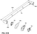
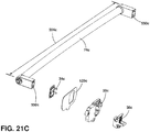
- the protruding handle 74 having a variety of different lengths and connecting portions (74a-74c) to an actuator attachment portion 558 ( FIG. 22 ) of the opening actuator 30 positioned in the door 22.
- the protruding handle 74 has a handle connecting portion 550 and a handle length 554 depending on the desired design and use of the protruding handle 74 on the door 22.
- the handle connecting portion 550 is coupled to the front bezel 34, the door wrapper 118, the intermediate attachment 58, and the handle pivot plate 38.
- a handle connecting portion 550a has a lengthened triangular shape that requires the same lengthened triangular shape in a front bezel 34a, a wrapper foam tape 120a, an intermediate attachment 58a, and a handle pivot plate 38a.
- a protruding handle 74b may have a shortened triangular connecting portion 550b and a shortened handle length 554b.
- a protruding handle 74c may have a shorter length handle length 554c and a rectangular handle connecting portion 550c.
- a front bezel 34c, a wrapper foam tape 120c, an intermediate attachment 58c, and a handle pivot plate 38c must all have the rectangular shape to couple the opening actuator 30 to the protruding handle 74c at a given length.
- the modular approach and mounting method is exemplified according to one aspect of the current disclosure.
- the three different alternatives include a) a lengthened triangular attachment portion 558a, b) a shortened triangular attachment portion 558b, and c) a rectangular attachment portion 558c.
- Each of the actuator attachment portions 558 includes the front bezel 34a-34c, the screw lug 154a-154c, the wrapper foam tape 120a-120c, the handle pivot plate 38a-38c, and the intermediate attachment 58a-58c.
- the shape of the handle connecting portion 550 on the protruding handle 74 ( FIGS. 21A-21C ) will determine which of the three actuator attachment portions 558 will be used.
- the handle length 554 of the protruding handle 74 ( FIGS. 21A-21C ) will determine which of the two actuator mechanisms 46 will be used.
- Actuator mechanism 46a includes a shortened lever 194a and surrounding casing 42a while the actuator mechanism 46b has a longer lever 194b and casing 42b for the protruding handle 74 having a shorter length.
- the actuator mechanism 46a-46b includes a casing 42a-42b, a top casing 148a-148b, a lever 194a-194b, a pusher arm 170a-170b, a bottom casing 186a-186b, a liner foam tape 122a-122b, and a back bezel 62a-62b.
- the protruding handle 74 having a shorter length would likely be used with the longer actuator mechanism 46b while the protruding handle 74b with a longer length would likely be used with the actuator mechanism 46a having a shorter length.
- wrapper and liner foam tape portions 120a-120c and 122a-122b are coupled to the inside of the door wrapper 118 and the door liner 122, respectively, to help prevent foam leaks.
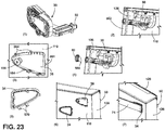
- a pre-foam assembly method is shown for coupling the opening actuator 30 to the door 22.
- the opening actuator 30 and its respective components are selected using the modular approach as previously described.
- the opening actuator 30 is coupled to the door wrapper 118 and the pusher arm 50 is positioned in a door panel 562.
- a plurality of locators 564 may be coupled to the door wrapper 118 to help maintain the positioning of the opening actuator 30.
- the back bezel 62 is coupled to the door panel 562 with one or more snaps 566 provided on the back bezel 62 to help lock the positioning of the opening actuator 30.
- the front bezel 34 has a plurality of snaps 570 that are used to couple the front bezel 34 to the door wrapper 118 further locking the position of the opening actuator 30 as shown in the sixth step.
- the protruding handle 74 is coupled to the opening actuator 30 using the screw lug 154 and the screw lug receiving member 158 (shown in FIG. 7 ).
- a method for installing the opening actuator 30 in the door 22 includes determining a distance between a pair of mounting holes on the door handle 26, determining a mounting profile for the door handle 26, selecting the casing 42 providing the desired distance between the pair of mounting holes on the door handle 26, selecting the pivot handle plate 38 that can be coupled to the mounting profile of the door handle 26, selecting the front bezel 34 and the intermediate attachment 58 to couple with the pivot handle plate 38 and casing 42, coupling the door handle 26 to the pivot handle plate 38, and coupling the front bezel 34 and the intermediate attachment 58 to the door handle 26 and the casing 42.
- the actuator mechanism 46 extends and retracts the pusher arm 50 against the front wrapper side 54 of the refrigerator 10.
- the term "coupled” in all of its forms, couple, coupling, coupled, etc. generally means the joining of two components (electrical or mechanical) directly or indirectly to one another. Such joining may be stationary in nature or movable in nature. Such joining may be achieved with the two components (electrical or mechanical) and any additional intermediate members being integrally formed as a single unitary body with one another or with the two components. Such joining may be permanent in nature or may be removable or releasable in nature unless otherwise stated.
- elements shown as integrally formed may be constructed of multiple parts or elements shown as multiple parts may be integrally formed, the operation of the interfaces may be reversed or otherwise varied, the length or width of the structures and/or members or connector or other elements of the system may be varied, the nature or number of adjustment positions provided between the elements may be varied.
- the elements and/or assemblies of the system may be constructed from any of a wide variety of materials that provide sufficient strength or durability, in any of a wide variety of colors, textures, and combinations. Accordingly, all such modifications are intended to be included within the scope of the present innovations. Other substitutions, modifications, changes, and omissions may be made in the design, operating conditions, and arrangement of the desired and other exemplary embodiments without departing from the spirit of the present innovations.
- Embodiment A is a refrigerator comprising: a refrigerator body having an interior storage space; a door coupled to the refrigerator body to open and close the interior storage space; a door handle coupled to the door in a pivotally rotatable manner; and an opening actuator coupled to the door handle wherein the opening actuator applies a force to the refrigerator body to open the interior storage space; wherein the opening actuator comprises a front bezel; a pivot handle plate coupled to the door handle; a casing enclosing an actuator mechanism and one or more pushers that extend and retract against a front wrapper side of the refrigerator body; an intermediate attachment coupling the handle pivot plate to the casing; and a back bezel.
- Embodiment A wherein the door handle is a protruding handle.
- the actuator mechanism comprises a lever coupled to the handle pivot and the pusher arm with a fulcrum near the center of the lever.
- the actuator mechanism comprises a flexible cable in contact with a first pulley and a second pulley wherein the flexible cable is coupled to the handle pivot and the pusher.
- Embodiment B is a door opening actuator for a refrigerator comprising: a front bezel; a pivot handle plate; an intermediate attachment; a casing; and a back bezel; wherein a door handle comprises a grip portion coupled to the opening actuator through the pivot handle plates; wherein the casing encloses an actuator mechanism that extends and retracts a pusher arm against a front wrapper side of the refrigerator to open a door pivotally coupled to the refrigerator to open and close an interior space.
- the door opening actuator for a refrigerator of Embodiment B or Embodiment B with any of the intervening features wherein the actuator mechanism comprises a flexible cable in contact with a first pulley and a second pulley wherein the flexible cable is coupled to the handle pivot and the pusher.
- Embodiment C is a method for installing an opening actuator for a refrigerator door, the method comprising: determining a distance between a pair of mounting holes on a door handle; determining a mounting profile for the door handle; selecting a casing providing the desired distance between the pair of mounting holes on the door handle; selecting a pivot handle plate that can be coupled to the mounting profile of the door handle; selecting a front bezel and an intermediate attachment to couple with the pivot handle plate and casing; coupling the door handle to the pivot handle plate; and coupling the front bezel and the intermediate attachment to the door handle and the casing; wherein an actuator mechanism extends and retracts a pusher arm against a front cabinet wrapper side of the refrigerator.
Landscapes
- Engineering & Computer Science (AREA)
- Chemical & Material Sciences (AREA)
- Combustion & Propulsion (AREA)
- Physics & Mathematics (AREA)
- Mechanical Engineering (AREA)
- Thermal Sciences (AREA)
- General Engineering & Computer Science (AREA)
- Refrigerator Housings (AREA)
Abstract
Description
- The present disclosure relates to a refrigerator, and in particular, to a refrigerator that uses a handle to activate a pushing device installed on a drawer or door of a refrigerator by using a mechanism to transfer movement from the handle to the pushing device to separate the door from the refrigerator main body.
- A refrigerator is an apparatus for storing foods or other materials at low temperatures to preserve the food or material in a refrigerated or frozen state according to the type and condition of desired preservation. Depending on the type of refrigerator, various types of doors for opening and closing the cabinet space are used. These doors typically have a graspable handle installed to allow a user to more easily open and close the door by grasping the door handle and pivoting the door to selectively open and close the cabinet space.
- When a user grasps a door handle to open the cabinet space of a refrigerator, a pulling force must be exerted that is sufficient enough to release the coupling force between the gasket of the door and the main body of the refrigerator. The seal of the door gasket along the main body is often increased because of the drop in pressure within the refrigerator due to temperature differences so that the door and the main body are pressed and/or sealed more firmly together. In many instances, the weight and seal of the refrigerator door to the main body can make the act of opening the door difficult or inconvenient for some users.
- According to one aspect of the present disclosure, a refrigerator is provided. The refrigerator includes a refrigerator body having an interior storage space, a door coupled to the refrigerator body to open and close the interior storage space, a door handle coupled to the door in a pivotally rotatable manner, and an opening actuator coupled to the door handle wherein the opening actuator applies a force to the refrigerator body to open the interior storage space. The opening actuator includes a front bezel, a pivot handle plate coupled to the door handle, a casing enclosing an actuator mechanism and one or more pusher arms that extend and retract against a front wrapper side of the refrigerator body, an intermediate attachment coupling the handle pivot plate to the casing, and a back bezel.
- According to a second aspect of the present disclosure, a door opening actuator for actuator for a refrigerator is provided. The door opening actuator includes a front bezel, a pivot handle plate, an intermediate attachment, a casing, and a back bezel. A door handle includes a grip portion coupled to the opening actuator through the pivot handle plates. The casing encloses an actuator mechanism that extends and retracts a pusher arm against a front wrapper side of the refrigerator to open a door pivotally coupled to the refrigerator to open and close an interior space.
- According to a third aspect of the present disclosure, a method for installing an opening actuator in a refrigerator door is provided. The method includes determining a distance between a pair of mounting holes on a door handle, determining a mounting profile for the door handle, selecting a casing providing the desired distance between the pair of mounting holes on the door handle, selecting a pivot handle plate that can be coupled to the mounting profile of the door handle, selecting a front bezel and an intermediate attachment to couple with the pivot handle plate and casing, coupling the door handle to the pivot handle plate, and coupling the front bezel and the intermediate attachment to the door handle and the casing. An actuator mechanism extends and retracts a pusher arm against a front cabinet wrapper side of the refrigerator.
- These and other features, advantages, and objects of the present invention will be further understood and appreciated by those skilled in the art by reference to the following specification, claims, and appended drawings.
-
-
FIG. 1 is a perspective view of a refrigerator according to one aspect of the present disclosure; -
FIG. 2 is a cross-sectional view of a pocket handle having a top actuation; -
FIG. 3 is a cross-sectional view of a pocket handle having a linear actuation; -
FIG. 4 is a cross-sectional view of a pocket handle having a bottom actuation; -
FIG. 5 is a front perspective view of a protruding handle with a Z lever mechanism having a straight extending pusher arm; -
FIG. 6 is a front perspective view of an isolated Z lever mechanism with a retracted straight extending pusher arm; -
FIG. 7 is a front perspective view of an isolated Z lever mechanism with an extended straight extending pusher arm; -
FIG. 8 is an exploded view of a Z lever mechanism having a straight extending pusher arm; -
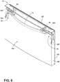
FIG. 9 is a front perspective view of a protruding handle having a pulley mechanism for a rotating pusher arm; -
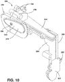
FIG. 10 is a front perspective of an actuator mechanism using a pulley mechanism with a retracted rotating pusher arm; -
FIG. 11 is a front perspective view of the actuator mechanism using a pulley mechanism with an extended rotating pusher arm; -
FIG. 12 is an exploded view of an actuator mechanism using a pulley mechanism with a rotating pusher arm; -
FIG. 13 is a front perspective view of a protruding handle coupled to an actuator mechanism using a pulley mechanism having straight extending pusher arms; -
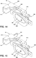
FIG. 14 is a front perspective view of a pulley mechanism having a retracted straight extending pusher arm; -
FIG. 15 is a front perspective view of an actuator mechanism using a pulley mechanism with an extended straight extending pusher arm; -
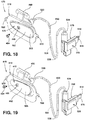
FIG. 16 is an exploded view of the pulley mechanism having a straight extending pusher arm; -
FIG. 17 is a front perspective of a protruding handle having an actuator mechanism using a sheathed cable mechanism using straight extending pusher arms; -
FIG. 18 is a front perspective of the sheathed cable mechanism having a retracted straight extending pusher arm; -
FIG. 19 is a front perspective of the sheathed cable mechanism having an extended straight extending pusher arm; -
FIG. 20 is a perspective view of a refrigerator body according to one aspect of the present disclosure; -
FIGS. 21A-21C are exploded views of various protruding handles and their coupling to an opening actuator; -
FIG. 22 is a modular approach to fitting a door handle to the appropriately fitted opening actuator according to one aspect of the present disclosure; and -
FIG. 23 shows a series of steps regarding a pre-foam assembly method for coupling an open actuator to a door according to one aspect of the present disclosure. - As required, detailed embodiments of the present disclosure are disclosed herein. However, it is to be understood that the disclosed embodiments are merely exemplary of the disclosure that may be embodied in various and alternative forms. The figures are not necessarily to a detailed design and some schematics may be exaggerated or minimized to show function overview. Therefore, specific structural and functional details disclosed herein are not to be interpreted as limiting, but merely as a representative basis for teaching one skilled in the art to variously employ the present disclosure.
- For purposes of description herein the terms "upper," "lower," "right," "left," "rear," "front," "vertical," "horizontal," and derivatives thereof shall relate to the device as oriented in
FIG. 1 . However, it is to be understood that the device may assume various alternative orientations and step sequences, except where expressly specified to the contrary. It is also to be understood that the specific devices and processes illustrated in the attached drawings, and described in the following specification are simply exemplary embodiments of the inventive concepts defined in the appended claims. Hence, specific dimensions and other physical characteristics relating to the embodiments disclosed herein are not to be considered as limiting, unless the claims expressly state otherwise. - As used herein, the term "and/or," when used in a list of two or more items, means that any one of the listed items can be employed by itself, or any combination of two or more of the listed items can be employed. For example, if a composition is described as containing components A, B, and/or C, the composition can contain A alone; B alone; C alone; A and B in combination; A and C in combination; B and C in combination; or A, B, and C in combination.
- Referring to
FIGS. 1-23 , arefrigerator 10 includes arefrigerator body 14 having aninterior storage space 18. Adoor 22 is coupled to therefrigerator body 14 to open and close theinterior storage space 18. Adoor handle 26 is coupled to thedoor 22 in a pivotally rotatable manner and anopening actuator 30 is coupled to thedoor handle 26 where theopening actuator 30 applies a force to therefrigerator body 14 to open theinterior storage space 18. Theopening actuator 30 includes afront bezel 34, apivot handle plate 38 coupled to thedoor handle 26, acasing 42 enclosing anactuator mechanism 46, and apusher arm 50 that extends and retracts against afront wrapper side 54 of therefrigerator body 14. An intermediate attachment 58 couples thepivot handle plate 38 to thecasing 42 and aback bezel 62. - Referring now to
FIG. 1 , therefrigerator 10 has therefrigerator body 14 enclosing theinterior storage spaces 18 and is pivotally or slidingly coupled to one ormore doors 22. The term "door 22," as defined herein, includes arefrigerator door 66, afreezer door 70, a refrigerator drawer, a freezer drawer, and/or a crisper drawer. In some embodiments, thedoor 22 may be pulled out towards the user as shown by the freezer door/drawer 70. Thedoor 22 has adoor handle 26, which may include a protrudinghandle 74 and/or apocket handle 78, to rotate and push/pull thedoor 22 open or closed so a user can access theinterior storage space 18. Therefrigerator 10 may include one ormore doors 22 to access one or moreinterior storage spaces 18 which may include a refrigerator storage space or a freezer storage space. Thedoors 22 may optionally include an ice and/or water dispenser. - The
refrigerator doors 66 andfreezer doors 70 disclosed herein may be used in a variety of configurations including French door, side-by-side, top freezer, bottom freezer, counter depth, compact, built-in, single door refrigerator, single door freezer, and other types of refrigerators and/or freezers. The disclosure herein describing embodiments for any refrigerator and/orfreezer door 70 applies equally as well to the other's application. - The refrigerator may have any of a known cooling system including a compressor, condenser, expansion valve, evaporator, conduits, and other related components (not shown). Alternatively, the
refrigerator 10 may comprise thermoelectric components (not shown), or other suitable arrangements depending on the intended use. - Any reference to the
opening actuator 30 being coupled to thedoor handle 26 to open thedoor 22 of therefrigerator 10 to access theinterior storage space 18 may be also used to at least partially describe refrigerator/freezer drawers. The drawer may be coupled to therefrigerator body 14 or other structure located in theinterior storage space 18 of therefrigerator 10. Some non-limiting examples of drawers may include a refrigerator drawer, a freezer drawer, and/or a pantry drawer. The description and each of the embodiments described below regarding thedoor 22 and door handle 26 may be substituted for drawer and drawer handle applications. - The
opening actuator device 30 disclosed herein for an easy open drawer/door with a rotating handle is operated through a combination of three different components. The three different components contained in these devices are: 1) the type ofdoor handle 26; 2) the type ofactuator mechanism 46 to transfer movement from thedoor handle 26 to thepusher arm 50; and 3) the type of movement for thepusher arm 50. Regarding the first component, thedoor handle 26 may include the protruding handle 74 (FIGS. 5 ,9 ,13 ,17 , and21A-21C ) and/or the pocket handle 78 (FIGS. 2-4 ) to rotate and push/pull thedoor 22 open or closed so a user can access theinterior storage space 18. For the second component, three differentsample actuator mechanisms 46 are disclosed herein to transfer movement from thedoor handle 26 to the pusher: a Z lever mechanism (FIGS. 5-8 and22-23 ); 2) a pulley mechanism (FIGS. 9-16 ); and 3) a sheathed cable mechanism (FIGS. 17-19 ). Regarding the third component, there are two examples for the types ofpusher arm 50 movement described herein: the straight extending pusher arm (FIGS. 5-8 ,13-19 , and22 ) and the rotating pusher arm (FIGS. 9-12 ). The various types ofpusher arms 50 may extend out against thefront wrapper side 54 of therefrigerator body 14 to break the seal of a gasket 128 (FIG. 5 ) around the edge of thedoor 22. In other embodiments, the various types ofpusher arms 50 may extend out and push against a refrigerator liner (not shown) to break the seal of thegasket 128 around the edge of thedoor 22. - Referring now to
FIGS. 2-4 , therefrigerator door 66 may have various embodiments of thepocket handle 78. InFIG. 2 , the pocket handle 78 has apocket bottom grip 82 having atop pivot point 86. A user would reach their hand into apocket receiving area 90 enclosed by apocket wall 94 to pull on thepocket bottom grip 82 and rotate it towards ahandle backstop 98. Thepocket bottom grip 82 having thetop pivot point 86 would have a top actuation mechanism for engaging the opening actuator 30 (FIG. 5 ). InFIG. 3 , the pocket handle 78 has apocket handle grip 102 with acenter mount 106 coupled to achannel 104. The user would pull thepocket handle grip 102 in a linear direction towards thehandle backstop 98 with thecenter mount 106 sliding along and positioned in thechannel 104. Thepocket handle grip 102 does not rotate and would have a linear actuation mechanism for engaging the openingactuator 30. InFIG. 4 , the pocket handle 78 has a pocket handletop grip 110 with abottom pivot point 114. The user can rotate the pocket handletop grip 110 counterclockwise around thebottom pivot point 114 to engage theopening actuator 30. The pocket handletop grip 110 having thebottom pivot point 114 would have a bottom actuation mechanism for engaging the openingactuator 30. - In some embodiments, the two examples of door handles 26 used with the opening
actuator 30 are the protrudinghandle 74 and thepocket handle 78. These types ofhandle 74 can be made from any suitable material for a desired feel, weight, and look for the user. The protrudinghandle 74 may be made into any shape or length and can be connected to an outside surface of thedoor 22 in any position. In some non-limiting embodiments, the protrudinghandle 74 is coupled in a vertical position along an edge of the door while in other embodiments the protrudinghandle 74 is coupled in a horizontal position along a top or bottom edge of the door. In other embodiments, the protrudinghandle 74 can be placed near the center of the door. Regardless of the construction or location of thedoor handle 26, thedoor handle 26 is connected to theopening actuator 30 to transfer movement from thedoor handle 26 topusher arm 50. This connection between thedoor handle 26 and the openingactuator 30 can be made at a single point with onediscrete opening actuator 30 to transfer movement from thedoor handle 26 to thepusher arm 50. Thedoor handle 26 may also be coupled to two openingactuators 30, for example, at each end of the protrudinghandle 74 on thedoor 22 or drawer. One ormore opening actuators 30 can be coupled to the protrudinghandle 74 in a variety of different locations. In some embodiments, the protrudinghandle 74 is coupled to two openingactuators 30 and in other embodiments the protrudinghandle 74 is connected to just oneopening actuator 30. - Referring now to
FIG. 5 , thefreezer door 70 is constructed from adoor wrapper 118 and adoor liner 122 having aside trim 126 coupling thewrapper 118 andliner 122. In some embodiments, theside trim 126 may be comprised of thedoor wrapper 118 extending around from the outside surface of thefreezer door 70 to couple thedoor liner 122. Thefreezer door 70 additionally has the protrudinghandle 74 coupled to theopening actuator 30 where theactuator mechanism 46 is aZ lever mechanism 130. TheZ lever mechanism 130 has a straight extending pusher arm 170 (FIG. 8 ) that extends out against the front wrapper side 54 (FIG. 20 ) of the refrigerator body 14 (FIG. 1 ) to break the seal of thegasket 128 around the edge of thefreezer door 70 in contact with thefront wrapper side 54 of therefrigerator body 14. - Referring now to
FIGS. 5-8 , theZ lever mechanism 130 includes apivot handle plate 134 having ahandle plate 138 and apivot handle shaft 142. The pivot handleplate 134 is positioned inside apivot handle mount 146 and anupper casing 148 with thepivot handle shaft 142 positioned inside a pivotshaft receiving member 150. The pivot handleplate 134 is coupled to the protrudinghandle 74 through ascrew lug 154 and a screwlug receiving member 158 where thepivot handle plate 134 can have thehandle plate 138 in a retractedposition 162 or anextended position 166. When thehandle plate 138 is in the retractedposition 162, the straight extendingpusher arm 170 is also in a retractedpusher arm position 174. In the retractedpusher arm position 174 thepivot handle plate 134 rests or is positioned against one ormore spacing members 178. When thehandle plate 138 is in theextended position 166, the straight extendingpusher arm 170 is also in an extendedpusher arm position 182. Alower casing 186 is coupled to theupper casing 148 through a plurality ofcoupling members 190 to enclose alever 194. Thelever 194 is made up of alever body 198, afulcrum member 202, and ahandle pivot arm 206 for transferring motion imparted by thepivot handle plate 134. Thelever 194 is coupled to the straight extendingpusher arm 170. Thefulcrum member 202 of thelever 194 is positioned in an upper 210 and a lower 214 fulcrum receiving member formed in the upper andlower casing spring 218 is additionally enclosed by the upper andlower casings spring 218 is positioned and partially compressed between aplunger spring wall 222 and aspring housing wall 226. Thespring 218 strength orspring 218 constant can be tuned to enhance the user's sensorial experience through touch. An adjustment of thespring 218 can be used to modify the resistance or retraction of thedoor handle 26 or for a better sensorial experience for the user interfacing with thedoor handle 26. - Referring now to
FIG. 9 , thefreezer door 70 is constructed from thedoor wrapper 118 and thedoor liner 122 with theside trim 126 connecting thewrapper 118 andliner 122. Thefreezer door 70 additionally has the protrudinghandle 74 coupled to theopening actuator 30. The openingactuator 30 has theactuation mechanism 46 which includes apulley mechanism 230 with arotating pusher arm 234. Thepulley mechanism 230 initiates therotating pusher arm 234 to rotate and push against the front wrapper side 54 (FIG. 20 ) of the refrigerator body 14 (FIG. 1 ) to break the seal of thegasket 128 around the edge of thefreezer door 70 in contact with thefront wrapper side 54 of therefrigerator body 14. - Referring now to
FIGS. 9-12 , thepulley mechanism 230 includes apivot handle plate 238 having ahandle plate 242 and apivot handle shaft 246. The pivot handleplate 238 is positioned inside apivot handle mount 250 and anupper casing 254 with thepivot handle shaft 246 positioned inside a pivotshaft receiving member 258. The pivot handleplate 238 is coupled to the protrudinghandle 74 through ascrew lug 262 and a screwlug receiving member 266. The pivot handleplate 238 can have thehandle plate 242 in a retractedhandle plate position 270 or in an extendedhandle plate position 274. In the retractedhandle plate position 270, therotating pusher arm 234 is in a retractedposition 282 or is rotated out of the way, and thepivot handle plate 238 rests or is positioned on one ormore spacing members 286. If thehandle plate 242 is in the extendedhandle plate position 274, therotating pusher arm 234 is in anextended plunger position 290 or is rotated out in contact with the front wrapper side 54 (FIG. 20 ) of the refrigerator body 14 (FIG. 1 ). Abottom casing member 294 is coupled to apulley casing cover 298 and aplunger casing cover 302 through a plurality ofcoupling members 306. Thecasing 42 made by thesecasing pieces first pulley 310 and asecond pulley 314 mounted on afirst pulley boss 318 and asecond pulley boss 322 with aflexible cable 326 positioned around the twopulleys pivot handle plate 238 and aplunger actuator 330. Anextension spring 334 is positioned on a top andbottom spring mount plunger actuator 330 which controls the articulating orrotating pusher arm 234. Theextension spring 334 strength orextension spring 334 constant can be tuned to enhance the user's sensorial experience through touch. An adjustment of theextension spring 334 can be used to modify the resistance or retraction of thedoor handle 26 or for a better sensorial experience for the user interfacing with the door handle 26 (FIG. 1 ). - Referring now to
FIG. 13 , thefreezer door 70 is constructed from thedoor wrapper 118 and thedoor liner 122 with the door side trim 126 connecting thewrapper 118 andliner 122. Thefreezer door 70 additionally has the protrudinghandle 74 coupled to theopening actuator 30. The openingactuator 30 has theactuator mechanism 46 which includes apulley mechanism 346 and a straight extendingpusher arm 350. Thepulley mechanism 346 extends the straight extendingpusher arm 350 to push directly outwards against the front wrapper side 54 (FIG. 20 ) of the refrigerator body 14 (FIG. 1 ) to break the seal of thegasket 128 around the edge of thefreezer door 70 in contact with thefront wrapper side 54 of therefrigerator body 14. - As shown in
FIGS. 13-16 , thepulley mechanism 346 has apivot handle plate 354 with ahandle plate 358 and apivot handle shaft 362. The pivot handleplate 354 is positioned inside apivot handle mount 366 and anupper casing member 418 with thepivot handle shaft 362 positioned inside a pivotshaft receiving member 378. The pivot handleplate 354 is coupled to the protrudinghandle 74 through ascrew lug 382 and a screwlug receiving member 386. The pivot handleplate 354 can have thehandle plate 358 in a retractedposition 390 or in an extendedhandle plate position 394. In the retractedhandle plate position 390, a straight extendingpusher arm 350 is in a retractedplunger position 402 and thepivot handle plate 354 rests or is positioned on one ormore spacing members 406. In the extendedhandle plate position 394, the straight extendingpusher arm 350 is in anextended plunger position 410 to be in contact with the front wrapper side 54 (FIG. 20 ) of the refrigerator body 14 (FIG. 1 ). Abottom casing member 414 couples theupper casing member 418 through a plurality ofcoupling members 422. Thecasing 42 made by thesecasing pieces cable receiving area 426 for aflexible cable 430, the straight extendingpusher arm 350, afirst pulley 434, and asecond pulley 438. The first andsecond pulleys first pulley boss 442 and asecond pulley boss 446, respectively, with theflexible cable 430 positioned around the first andsecond pulleys pivot handle plate 354 and acable connecting member 450. Aspring 454 is compressed and positioned in aspring receiving area 458 between aplunger spring wall 462 and aspring stopping wall 466. Thespring 454 strength orspring 454 constant can be tuned to enhance the user's sensorial experience through touch. An adjustment of thespring 454 can be used to modify the resistance or retraction of thedoor handle 26 or for a better sensorial experience for the user interfacing with the door handle 26 (FIG. 1 ). - Referring now to
FIG. 17 , thefreezer door 70 is made from thedoor wrapper 118 and thedoor liner 122 which are coupled through the door side trim 126 connecting thewrapper 118 andliner 122. Thefreezer door 70 additionally includes the protrudinghandle 74 coupled to theopening actuator 30. The openingactuator 30 has theactuator mechanism 46 which includes a sheathedcable mechanism 470 and a straight extendingpusher arm 474 where the straight extendingpusher arm 474 pushes directly outwards against the front wrapper side 54 (FIG. 20 ) of the refrigerator body 14 (FIG. 1 ) to break the seal of thegasket 128 around the edge of thefreezer door 70 in contact with thefront wrapper side 54 of therefrigerator body 14. - Referring now to
FIGS. 17-19 , the sheathedcable mechanism 470 has apivot handle plate 478 with ahandle plate 482 and a pivot handle shaft (not shown) positioned in a pivotshaft receiving member 490. The pivot handleplate 478 is coupled to the protrudinghandle 74 through ascrew lug 494 and a screwlug receiving member 498 while thepivot handle plate 478 can have thehandle plate 482 in a retractedhandle plate position 502 or an extendedhandle plate position 506. In the retracted handle plate position 502 a straight extendingpusher arm 474 is in a retractedplunger position 512 and thepivot handle plate 478 rests or is positioned on one or more spacing members (not shown). In the extendedhandle plate position 506, the straight extendingpusher arm 474 is anextended plunger position 514. The pivot handleplate 478 is positioned in anupper casing 518 with atop cable fastener 520 that is coupled together through a plurality ofcoupling members 522 while abottom cable fastener 524 and the straight extendingpusher arm 474 are positioned in a lowerplunger casing member 526. The straight extendingpusher arm 474 is positioned in thelower plunger casing 526 having aplunger casing cover 528. A sheathedcable 530 has aflexible cable 534 positioned inside aflexible sheath 538 where theflexible sheath 538 may be made from a thermoplastic or thermoset polymer. - The disclosure herein encompasses any combination using the options discussed herein regarding the
door handle 26,actuator mechanism 46, and type ofpusher arm 50 movement. For example, in some embodiments, the protrudinghandle 74 may be used with theZ lever mechanism 130 and the straight extending pusher arm 170 (seeFIGS. 5-8 ). In other embodiments, the protrudinghandle 74 may be used with theZ level mechanism 130 and therotating pusher arm 234. In other embodiments, the protrudinghandle 74 may be used with thepulley mechanism 230 and the rotating pusher arm 234 (seeFIGS. 9-12 ). In other embodiments, the protrudinghandle 74 may be used with thepulley mechanism 346 and the straight extending pusher arm 350 (seeFIGS. 13-16 ). In still other embodiments, the protrudinghandle 74 may be used with the sheathedcable mechanism 470 and therotating pusher arm 234. In yet other embodiments, the protrudinghandle 74 may be used with the sheathedcable mechanism 470 and the straight extending pusher arm 474 (seeFIGS. 17-19 ) - In some embodiments, the pocket handle 78 (top actuation, linear actuation, or bottom actuation) may be used with the
Z lever mechanism 130 and the straight extendingpusher arm 170. In other embodiments, the pocket handle 78 (top actuation, linear actuation, or bottom actuation) may be used with theZ lever mechanism 130 and therotating pusher arm 234. In other embodiments, the pocket handle 78 (top actuation, linear actuation, or bottom actuation) may be used with thepulley mechanism 230 and therotating pusher arm 234. In other embodiments, the pocket handle 78 (top actuation, linear actuation, or bottom actuation) may be used with thepulley mechanism 230 and the straight extendingpusher arm 170. In other embodiments, the pocket handle 78 (top actuation, linear actuation, or bottom actuation) may be used with the sheathedcable mechanism 470 and therotating pusher arm 234. In other embodiments, the pocket handle 78 (top actuation, linear actuation, or bottom actuation) may be used with the sheathedcable mechanism 470 and the straight extendingpusher arm 474. - Referring now to
FIG. 20 , therefrigerator body 14 includes abody wrapper 542, abody liner 546, and thefront wrapper side 54. Thefront wrapper side 54 extends around the perimeter of theinterior storage space 18 of therefrigerator body 14. Thefront wrapper edge 54 may not include any edges or surfaces formed by a mullion separating one or moreinterior storage spaces 18. - Referring now to
FIGS. 21A-21C , a modular approach and mounting method is provided to couple the protrudinghandle 74 having a variety of different lengths and connecting portions (74a-74c) to an actuator attachment portion 558 (FIG. 22 ) of the openingactuator 30 positioned in thedoor 22. As discussed above, the protrudinghandle 74 has a handle connecting portion 550 and a handle length 554 depending on the desired design and use of the protrudinghandle 74 on thedoor 22. In general, the handle connecting portion 550 is coupled to thefront bezel 34, thedoor wrapper 118, the intermediate attachment 58, and thehandle pivot plate 38. Depending on the handle connecting portion 550 and the handle length 554, a variety of different designs for the actuator attachment portion 558 of the openingactuator 30 may be required. For example, inFIG. 21A , ahandle connecting portion 550a has a lengthened triangular shape that requires the same lengthened triangular shape in afront bezel 34a, awrapper foam tape 120a, anintermediate attachment 58a, and ahandle pivot plate 38a. In another embodiment shown inFIG. 21B , a protrudinghandle 74b may have a shortenedtriangular connecting portion 550b and a shortenedhandle length 554b. As a result, the actuator attachment portion 558 will require the same shortened triangular shape in afront bezel 34b, awrapper foam tape 120b, anintermediate attachment 58b, and ahandle pivot plate 38b. In yet another embodiment shown inFIG. 21C , a protrudinghandle 74c may have a shorterlength handle length 554c and a rectangularhandle connecting portion 550c. As a result, afront bezel 34c, awrapper foam tape 120c, anintermediate attachment 58c, and ahandle pivot plate 38c, must all have the rectangular shape to couple theopening actuator 30 to the protrudinghandle 74c at a given length. - Referring now to
FIG. 22 , the modular approach and mounting method is exemplified according to one aspect of the current disclosure. In this modular approach, three different alternatives are shown for the actuator attachment portion 558 and two different alternatives are given for theactuator mechanism 46. For the actuator attachment portion 558, the three different options include a) a lengthenedtriangular attachment portion 558a, b) a shortenedtriangular attachment portion 558b, and c) arectangular attachment portion 558c. Each of the actuator attachment portions 558 includes thefront bezel 34a-34c, thescrew lug 154a-154c, thewrapper foam tape 120a-120c, thehandle pivot plate 38a-38c, and theintermediate attachment 58a-58c. The shape of the handle connecting portion 550 on the protruding handle 74 (FIGS. 21A-21C ) will determine which of the three actuator attachment portions 558 will be used. In addition, the handle length 554 of the protruding handle 74 (FIGS. 21A-21C ) will determine which of the twoactuator mechanisms 46 will be used.Actuator mechanism 46a includes a shortenedlever 194a and surroundingcasing 42a while theactuator mechanism 46b has alonger lever 194b andcasing 42b for the protrudinghandle 74 having a shorter length. In both options, theactuator mechanism 46a-46b includes acasing 42a-42b, atop casing 148a-148b, alever 194a-194b, apusher arm 170a-170b, abottom casing 186a-186b, aliner foam tape 122a-122b, and aback bezel 62a-62b. The protrudinghandle 74 having a shorter length would likely be used with thelonger actuator mechanism 46b while the protrudinghandle 74b with a longer length would likely be used with theactuator mechanism 46a having a shorter length. The wrapper and linerfoam tape portions 120a-120c and 122a-122b are coupled to the inside of thedoor wrapper 118 and thedoor liner 122, respectively, to help prevent foam leaks. Using this modular approach to couple theopening actuator 30 to the protrudinghandle 74 gives designers and users the opportunity to custom build therefrigerator 10 with the desired functionality and aesthetics desired to easily open thedoor 22 with the openingactuator 30. - Referring now to
FIG. 23 , a pre-foam assembly method is shown for coupling theopening actuator 30 to thedoor 22. First, the openingactuator 30 and its respective components are selected using the modular approach as previously described. Second, the openingactuator 30 is coupled to thedoor wrapper 118 and thepusher arm 50 is positioned in adoor panel 562. Third, a plurality oflocators 564 may be coupled to thedoor wrapper 118 to help maintain the positioning of the openingactuator 30. Forth, theback bezel 62 is coupled to thedoor panel 562 with one ormore snaps 566 provided on theback bezel 62 to help lock the positioning of the openingactuator 30. Fifth, thefront bezel 34 has a plurality ofsnaps 570 that are used to couple thefront bezel 34 to thedoor wrapper 118 further locking the position of the openingactuator 30 as shown in the sixth step. Seventh, the protrudinghandle 74 is coupled to theopening actuator 30 using thescrew lug 154 and the screw lug receiving member 158 (shown inFIG. 7 ). - Referring to
FIGS. 21A to 23 , a method for installing the openingactuator 30 in thedoor 22 is provided. The method includes determining a distance between a pair of mounting holes on thedoor handle 26, determining a mounting profile for thedoor handle 26, selecting thecasing 42 providing the desired distance between the pair of mounting holes on thedoor handle 26, selecting thepivot handle plate 38 that can be coupled to the mounting profile of thedoor handle 26, selecting thefront bezel 34 and the intermediate attachment 58 to couple with thepivot handle plate 38 andcasing 42, coupling thedoor handle 26 to thepivot handle plate 38, and coupling thefront bezel 34 and the intermediate attachment 58 to thedoor handle 26 and thecasing 42. Theactuator mechanism 46 extends and retracts thepusher arm 50 against thefront wrapper side 54 of therefrigerator 10. - It is understood that the descriptions outlining and teaching the opening
actuator 30 and the modular approach and mounting method previously discussed herein, which can be used in any combination, apply equally well to the method described inFIGS. 21A to 23 , where applicable, further disclosing the method for installing the openingactuator 30 in thedoor 22. - In this specification and the appended claims, the singular forms "a," "an" and "the" include plural reference unless the context clearly dictates otherwise. For the purposes of describing and defining the present teachings, it is noted that the terms "substantially" and "approximately" are utilized herein to represent the inherent degree of uncertainty that may be attributed to any quantitative comparison, value, measurement, or other representation. The term "substantially" and "approximately" are also utilized herein to represent the degree by which a quantitative representation may vary from a stated reference without resulting in a change in the basic function of the subject matter at issue.
- It is to be understood that the present disclosure is not limited to the particular embodiments described below, as variations of the particular embodiments may be made and still fall within the scope of the appended claims. It is also to be understood that the terminology employed is for the purpose of describing particular embodiments, and is not intended to be limiting. Instead, the scope of the present disclosure will be established by the appended claims.
- It will be understood by one having ordinary skill in the art that construction of the described device and other components is not limited to any specific material. Other exemplary embodiments of the device disclosed herein may be formed from a wide variety of materials, unless described otherwise herein.
- For purposes of this disclosure, the term "coupled" (in all of its forms, couple, coupling, coupled, etc.) generally means the joining of two components (electrical or mechanical) directly or indirectly to one another. Such joining may be stationary in nature or movable in nature. Such joining may be achieved with the two components (electrical or mechanical) and any additional intermediate members being integrally formed as a single unitary body with one another or with the two components. Such joining may be permanent in nature or may be removable or releasable in nature unless otherwise stated.
- It is also important to note that the construction and arrangement of the elements of the device as shown in the exemplary embodiments is illustrative only. Although only a few embodiments of the present innovations have been described in detail in this disclosure, those skilled in the art who review this disclosure will readily appreciate that many modifications are possible (e.g., variations in sizes, dimensions, structures, shapes and proportions of the various elements, values of parameters, mounting arrangements, use of materials, colors, orientations, etc.) without materially departing from the novel teachings and advantages of the subject matter recited. For example, elements shown as integrally formed may be constructed of multiple parts or elements shown as multiple parts may be integrally formed, the operation of the interfaces may be reversed or otherwise varied, the length or width of the structures and/or members or connector or other elements of the system may be varied, the nature or number of adjustment positions provided between the elements may be varied. It should be noted that the elements and/or assemblies of the system may be constructed from any of a wide variety of materials that provide sufficient strength or durability, in any of a wide variety of colors, textures, and combinations. Accordingly, all such modifications are intended to be included within the scope of the present innovations. Other substitutions, modifications, changes, and omissions may be made in the design, operating conditions, and arrangement of the desired and other exemplary embodiments without departing from the spirit of the present innovations.
- It will be understood that any described processes or steps within described processes may be combined with other disclosed processes or steps to form structures within the scope of the present device. The exemplary structures and processes disclosed herein are for illustrative purposes and are not to be construed as limiting.
- The above description is considered that of the illustrated embodiments only. Modifications of the device will occur to those skilled in the art and to those who make or use the device. Therefore, it is understood that the embodiments shown in the drawings and described above is merely for illustrative purposes and not intended to limit the scope of the device, which is defined by the following claims as interpreted according to the principles of patent law, including the Doctrine of Equivalents.
- Embodiment A is a refrigerator comprising: a refrigerator body having an interior storage space; a door coupled to the refrigerator body to open and close the interior storage space; a door handle coupled to the door in a pivotally rotatable manner; and an opening actuator coupled to the door handle wherein the opening actuator applies a force to the refrigerator body to open the interior storage space; wherein the opening actuator comprises a front bezel; a pivot handle plate coupled to the door handle; a casing enclosing an actuator mechanism and one or more pushers that extend and retract against a front wrapper side of the refrigerator body; an intermediate attachment coupling the handle pivot plate to the casing; and a back bezel.
- The refrigerator of Embodiment A wherein the door handle is a protruding handle.
- The refrigerator of Embodiment A or Embodiment A with any of the intervening features wherein the door handle is a pocket handle having a top actuation, a linear actuation, or a bottom actuation.
- The refrigerator of Embodiment A or Embodiment A with any of the intervening features wherein the actuator mechanism comprises a lever coupled to the handle pivot and the pusher arm with a fulcrum near the center of the lever.
- The refrigerator of Embodiment A or Embodiment A with any of the intervening features wherein the actuator mechanism comprises a flexible cable in contact with a first pulley and a second pulley wherein the flexible cable is coupled to the handle pivot and the pusher.
- The refrigerator of Embodiment A or Embodiment A with any of the intervening features wherein the actuator mechanism comprises a sheathed cable connected to the handle pivot and the pusher.
- The refrigerator of Embodiment A or Embodiment A with any of the intervening features wherein the pusher arm is configured to be linearly retracted from and linearly extended against the front wrapper side of the refrigerator.
- The refrigerator of Embodiment A or Embodiment A with any of the intervening features wherein the pusher arm is configured to be rotatably retracted from and rotatably extended against the front wrapper side of the refrigerator.
- Embodiment B is a door opening actuator for a refrigerator comprising: a front bezel; a pivot handle plate; an intermediate attachment; a casing; and a back bezel; wherein a door handle comprises a grip portion coupled to the opening actuator through the pivot handle plates; wherein the casing encloses an actuator mechanism that extends and retracts a pusher arm against a front wrapper side of the refrigerator to open a door pivotally coupled to the refrigerator to open and close an interior space.
- The door opening actuator for a refrigerator of Embodiment B wherein the door handle is a protruding handle.
- The door opening actuator for a refrigerator of Embodiment B or Embodiment B with any of the intervening features wherein the door handle is a pocket handle having a top actuation, a linear actuation, or a bottom actuation.
- The door opening actuator for a refrigerator of Embodiment B or Embodiment B with any of the intervening features wherein the actuator mechanism comprises a lever coupled to the handle pivot and the pusher arm with a fulcrum near the center of the lever.
- The door opening actuator for a refrigerator of Embodiment B or Embodiment B with any of the intervening features wherein the actuator mechanism comprises a flexible cable in contact with a first pulley and a second pulley wherein the flexible cable is coupled to the handle pivot and the pusher.
- The door opening actuator for a refrigerator of Embodiment B or Embodiment B with any of the intervening features wherein the actuator mechanism comprises a sheathed cable connected to the handle pivot and the pusher.
- The door opening actuator for a refrigerator of Embodiment B or Embodiment B with any of the intervening features wherein the pusher arm is configured to be linearly retracted from and linearly extended against the front wrapper side of the refrigerator.
- The door opening actuator for a refrigerator of Embodiment B or Embodiment B with any of the intervening features wherein the pusher arm is configured to be rotatably retracted from and rotatably extended against the front wrapper side of the refrigerator.
- Embodiment C is a method for installing an opening actuator for a refrigerator door, the method comprising: determining a distance between a pair of mounting holes on a door handle; determining a mounting profile for the door handle; selecting a casing providing the desired distance between the pair of mounting holes on the door handle; selecting a pivot handle plate that can be coupled to the mounting profile of the door handle; selecting a front bezel and an intermediate attachment to couple with the pivot handle plate and casing; coupling the door handle to the pivot handle plate; and coupling the front bezel and the intermediate attachment to the door handle and the casing; wherein an actuator mechanism extends and retracts a pusher arm against a front cabinet wrapper side of the refrigerator.
- The method for installing an opening actuator for a refrigerator of Embodiment C wherein the door handle is a protruding handle.
- The method for installing an opening actuator for a refrigerator of Embodiment C or Embodiment C with any of the intervening features wherein the actuator mechanism comprises a lever coupled to the handle pivot and the pusher arm with a fulcrum near the center of the lever.
- The method for installing an opening actuator for a refrigerator of Embodiment C or Embodiment C with any of the intervening features wherein the actuator mechanism comprises a flexible cable in contact with a first pulley and a second pulley wherein the flexible cable is coupled to the handle pivot and the pusher.
Claims (15)
- A refrigerator (10) comprising:a refrigerator body (14) having an interior storage space (18);a door (22) coupled to the refrigerator body (14) to open and close the interior storage space (18);a door handle (26) coupled to the door (22) in a pivotally rotatable manner; andan opening actuator (30) coupled to the door handle (26) wherein the opening actuator 30 applies a force to the refrigerator body (14) to open the interior storage space (18);wherein the opening actuator (30) comprises:a front bezel (34);a pivot handle plate (38) coupled to the door handle (26);a casing (42) enclosing an actuator mechanism (46) and one or more pusher arms (50) that extend and retract against a front wrapper side (54) of the refrigerator body 14;an intermediate attachment (58) coupling the handle pivot plate (38) to the casing (42); anda back bezel (62).
- The refrigerator (10) of claim 1, wherein the door (22) is a refrigerator door (66) pivotally coupled to the refrigerator body (14) to open and close the interior storage space (18).
- The refrigerator (10) of either of claims 1 and 2, wherein the door is a freezer door (70) coupled to the refrigerator body (14) to open and close the interior storage space (18).
- The refrigerator (10) of any of claims 1-3, wherein the door handle (26) is a protruding handle (74).
- The refrigerator (10) of any of claims 1-3, wherein the door handle (26) is a pocket handle (78) having a top actuation.
- The refrigerator (10) of any of claims 1-3, wherein the door handle (26) is a pocket handle (78) having a linear actuation.
- The refrigerator (10) of any of claims 1-3, wherein the door handle (26) is a pocket handle (78) having a bottom actuation.
- The refrigerator (10) of any of claims 1-7, wherein the actuator mechanism (46) comprises a Z level mechanism (130), a pulley mechanism (230), and/or a sheathed cable mechanism (470).
- The refrigerator (10) of any of claims 1-7, wherein the actuator mechanism (46) comprises a lever (194) coupled to both the pivot handle plate (134) and the pusher arm (50) with a fulcrum member (202) near the center of the lever (194).
- The refrigerator (10) of any of claims 1-7, wherein the actuator mechanism (46) comprises a flexible cable (326) in contact with one or more pulleys (310) wherein the flexible cable (326) is coupled to the pivot handle plate (38) and the pusher arm (50).
- The refrigerator (10) of any of claims 1-7, wherein the actuator mechanism (46) comprises a flexible cable (326) in contact with a first pulley (310) and a second pulley (314) wherein the flexible cable (326) is coupled to the pivot handle plate (38) and the pusher arm (50).
- The refrigerator (10) of any of claims 1-7, wherein the actuator mechanism (46) comprises a sheathed cable (530) connected to the pivot handle plate (38) and the pusher arm(50).
- The refrigerator (10) of any of claims 1-12, wherein the opening actuator (30) applies the force to the refrigerator body (14) with the one or more pusher arms (50) that extend and retract against the front wrapper side (54) of the refrigerator body (14) to break a seal of a gasket (128).
- The refrigerator (10) of any of claims 1-13, wherein the pusher arm (50) is configured to be linearly retracted from and linearly extended against the front wrapper side (54) of the refrigerator body (14).
- The refrigerator (10) of any of claims 1-13, wherein the pusher arm (50) is configured to be rotatably retracted from and rotatably extended against the front wrapper side (54) of the refrigerator body (14).
Applications Claiming Priority (2)
| Application Number | Priority Date | Filing Date | Title |
|---|---|---|---|
| US201562271451P | 2015-12-28 | 2015-12-28 | |
| US15/376,159 US10684063B2 (en) | 2015-12-28 | 2016-12-12 | Easy open drawer/door with rotating handle |
Publications (1)
| Publication Number | Publication Date |
|---|---|
| EP3187803A1 true EP3187803A1 (en) | 2017-07-05 |
Family
ID=57570342
Family Applications (1)
| Application Number | Title | Priority Date | Filing Date |
|---|---|---|---|
| EP16204554.6A Withdrawn EP3187803A1 (en) | 2015-12-28 | 2016-12-15 | Easy open drawer/door with a rotating handle |
Country Status (2)
| Country | Link |
|---|---|
| US (2) | US10684063B2 (en) |
| EP (1) | EP3187803A1 (en) |
Cited By (1)
| Publication number | Priority date | Publication date | Assignee | Title |
|---|---|---|---|---|
| CN109827372A (en) * | 2019-01-11 | 2019-05-31 | 海信容声(广东)冷柜有限公司 | A kind of cold storage plant |
Families Citing this family (12)
| Publication number | Priority date | Publication date | Assignee | Title |
|---|---|---|---|---|
| US11008775B2 (en) * | 2015-12-03 | 2021-05-18 | Lawrence E Chaffin | Lift glide door lock assembly and lift glide window lock assembly and dual lift glide door lock assembly and dual lift glide window lock assembly |
| US10684063B2 (en) * | 2015-12-28 | 2020-06-16 | Whirlpool Corporation | Easy open drawer/door with rotating handle |
| USD901277S1 (en) * | 2016-12-22 | 2020-11-10 | Whirlpool Corporation | Handle |
| CN109855348B (en) * | 2017-11-30 | 2020-03-31 | 青岛海尔股份有限公司 | Refrigerating and freezing device |
| KR102614492B1 (en) | 2018-12-21 | 2023-12-15 | 엘지전자 주식회사 | Refrigerator |
| US11920382B2 (en) | 2020-09-15 | 2024-03-05 | Midea Group Co., Ltd. | Rotating support handle assembly for bottom-hinged door |
| CN114507971B (en) * | 2020-10-23 | 2025-09-26 | 博西华电器(江苏)有限公司 | Linking device and clothes processing equipment including the same |
| CN113701442A (en) * | 2021-09-07 | 2021-11-26 | 长虹美菱股份有限公司 | Locking mechanism for refrigerator drawer |
| CN113776257A (en) * | 2021-10-15 | 2021-12-10 | 浙江爱雪制冷电器有限公司 | Four-door single-unit single-temperature refrigerator |
| US12038218B2 (en) | 2022-05-26 | 2024-07-16 | Midea Group Co., Ltd. | Method and apparatus for articulating feet of a freezer door |
| KR20240086995A (en) * | 2022-12-12 | 2024-06-19 | 엘지전자 주식회사 | Refrigeratgor |
| US12209793B2 (en) | 2022-12-19 | 2025-01-28 | Midea Group Co., Ltd. | Method and apparatus for rotating a pocket recess of a freezer door |
Citations (6)
| Publication number | Priority date | Publication date | Assignee | Title |
|---|---|---|---|---|
| WO2012007217A1 (en) * | 2010-07-16 | 2012-01-19 | Vestel Beyaz Esya Sanayi Ve Ticaret A.S. | Door opening mechanism for cooler devices |
| EP2520885A2 (en) * | 2011-05-04 | 2012-11-07 | LG Electronics Inc. | Refrigerator |
| DE102013103821A1 (en) * | 2013-04-16 | 2014-10-16 | Miele & Cie. Kg | cooling unit |
| CN102661082B (en) * | 2012-05-10 | 2014-10-22 | 合肥美的电冰箱有限公司 | Doorknob assembly and door body with same and refrigerator with same |
| WO2014194953A1 (en) * | 2013-06-06 | 2014-12-11 | Arcelik Anonim Sirketi | Refrigeration appliance double-action handle mechanism |
| US20150292793A1 (en) * | 2014-04-14 | 2015-10-15 | General Electric Company | Appliance with an articulating handle |
Family Cites Families (98)
| Publication number | Priority date | Publication date | Assignee | Title |
|---|---|---|---|---|
| US2659115A (en) | 1950-03-27 | 1953-11-17 | Jervis Corp | Magnetic door seal |
| US2810493A (en) | 1955-05-11 | 1957-10-22 | Whirlpool Seeger Corp | Vacuum release mechanism for refrigerated cabinet |
| DE10230707A1 (en) | 2002-07-08 | 2004-01-22 | BSH Bosch und Siemens Hausgeräte GmbH | Refrigerator with door opening aid |
| DE10226620A1 (en) | 2002-06-14 | 2003-12-24 | Bsh Bosch Siemens Hausgeraete | Refrigerator with door opening aid |
| KR970007468B1 (en) | 1993-11-30 | 1997-05-09 | 아남산업 주식회사 | Lead frame |
| KR0139299Y1 (en) | 1996-08-14 | 1999-05-15 | 김광호 | Door of a refrigerator |
| JP3045983B2 (en) | 1996-10-25 | 2000-05-29 | 三星電子株式会社 | Refrigerator door device |
| TW487798B (en) | 1998-08-04 | 2002-05-21 | Matsushita Refrigeration Co Lt | Refrigerator |
| ATE318359T1 (en) | 1998-08-19 | 2006-03-15 | Fisher & Paykel Appliances Ltd | DOOR OPENING AND CLOSING SYSTEM |
| JP2000205740A (en) | 1999-01-20 | 2000-07-28 | Fujitsu General Ltd | Electric refrigerator handle device |
| DE19906659A1 (en) | 1999-02-18 | 2000-08-24 | Aeg Hausgeraete Gmbh | Cooling and/or freezing apparatus has door handle with comparatively long, essentially straight handle element and cylindrical plug-in peg standing at almost right angle. |
| JP2000279283A (en) | 1999-03-31 | 2000-10-10 | Sanyo Electric Co Ltd | Low-temperature showcase |
| KR100596533B1 (en) | 1999-09-04 | 2006-07-06 | 삼성전자주식회사 | Door handles of the refrigerator |
| US6527315B2 (en) * | 2000-12-22 | 2003-03-04 | Whirlpool Corporation | Door latch for a dishwasher |
| CN1537347A (en) * | 2001-06-01 | 2004-10-13 | �Ƹ��� | Latch with clamp-on mounting |
| US6746091B2 (en) * | 2001-12-05 | 2004-06-08 | Artromick International, Inc. | Cart locking device |
| DE10208457A1 (en) * | 2002-02-27 | 2003-09-04 | Bsh Bosch Siemens Hausgeraete | Household appliance and appliance door |
| DE10208472A1 (en) * | 2002-02-27 | 2003-09-25 | Bsh Bosch Siemens Hausgeraete | household appliance |
| DE10208471A1 (en) * | 2002-02-27 | 2003-09-04 | Bsh Bosch Siemens Hausgeraete | Method of manufacturing a household appliance and a household appliance |
| DE10208496A1 (en) * | 2002-02-27 | 2003-10-16 | Bsh Bosch Siemens Hausgeraete | Household appliance and appliance door |
| DE10208490A1 (en) * | 2002-02-27 | 2004-02-05 | BSH Bosch und Siemens Hausgeräte GmbH | household appliance |
| JP4043970B2 (en) | 2003-02-13 | 2008-02-06 | 三菱電機株式会社 | Opening and closing mechanism of the refrigerator |
| SE0301533D0 (en) | 2003-05-23 | 2003-05-23 | Electrolux Home Prod Corp | Handle |
| DE10347760A1 (en) | 2003-10-14 | 2005-05-12 | Liebherr Hausgeraete | Door handle for opening a refrigerator or freezer compartment door |
| JP2005127656A (en) | 2003-10-27 | 2005-05-19 | Matsushita Electric Ind Co Ltd | refrigerator |
| EP1711760B1 (en) | 2003-12-10 | 2010-01-20 | Arcelik Anonim Sirketi | A refrigerator |
| US20050200253A1 (en) | 2004-03-11 | 2005-09-15 | John Wissinger | Spring biased latching arrangement for a refrigerator door |
| JP2005299314A (en) | 2004-04-15 | 2005-10-27 | Matsushita Electric Ind Co Ltd | Refrigerator door opener |
| AU2005262262B2 (en) | 2004-07-08 | 2010-06-10 | David Stuckey Investments Pty Ltd | Handle assembly |
| JP2006037652A (en) | 2004-07-29 | 2006-02-09 | Takigen Mfg Co Ltd | Lock handle device for door with internal unlocking mechanism |
| KR20060020079A (en) | 2004-08-31 | 2006-03-06 | 엘지전자 주식회사 | Refrigerator door opening |
| KR100675795B1 (en) | 2004-11-05 | 2007-02-02 | 삼성전자주식회사 | How to open the doors of double door refrigerators and double door refrigerators |
| US8516659B2 (en) | 2005-01-12 | 2013-08-27 | Whirlpool Corporation | Refrigerator handle mounting arrangement having pin and cavity interlock |
| DE202005002960U1 (en) | 2005-01-21 | 2006-06-01 | Liebherr-Hausgeräte Ochsenhausen GmbH | Refrigerator and / or freezer door handle |
| US7559119B2 (en) * | 2005-01-27 | 2009-07-14 | Maytag Corporation | Refrigerator handle mounting arrangement |
| JP4104606B2 (en) | 2005-03-30 | 2008-06-18 | 三洋電機株式会社 | Cryogenic door device |
| EP1909631B1 (en) * | 2005-06-24 | 2012-01-18 | Arçelik Anonim Sirketi | A household appliance with adjustment mechanism for the door weight compensation device |
| DE202006007722U1 (en) | 2006-05-15 | 2006-07-13 | BSH Bosch und Siemens Hausgeräte GmbH | Refrigerator comprises an integrated freezer compartment having a door body and a handle part having protrusions orientated across a pivoting axle |
| JP2007321531A (en) | 2006-06-05 | 2007-12-13 | Takigen Mfg Co Ltd | Lock handle device for doors. |
| KR20080001006A (en) | 2006-06-28 | 2008-01-03 | 삼성전자주식회사 | Refrigerator |
| US8099970B2 (en) | 2006-12-08 | 2012-01-24 | Samsung Electronics Co., Ltd. | Refrigerator door opening device and control method thereof |
| KR20080100553A (en) | 2007-05-14 | 2008-11-19 | 엘지전자 주식회사 | Refrigerator door opening structure |
| KR20080100555A (en) | 2007-05-14 | 2008-11-19 | 엘지전자 주식회사 | Refrigerator Door Opening Structure |
| US20090025183A1 (en) * | 2007-07-26 | 2009-01-29 | Ideal Security Inc. | Pull-handle assembly |
| US7901019B2 (en) | 2007-12-28 | 2011-03-08 | General Electric Company | Door assembly for use in a home appliance |
| KR101484039B1 (en) | 2008-01-11 | 2015-01-20 | 삼성전자 주식회사 | An opening device for refrigerator |
| KR101600310B1 (en) * | 2008-02-20 | 2016-03-09 | 삼성전자 주식회사 | Refrigerator |
| CN201165778Y (en) | 2008-02-22 | 2008-12-17 | 美的集团电冰箱制造(合肥)有限公司 | Booster door handles |
| JP4464443B2 (en) | 2008-02-25 | 2010-05-19 | タキゲン製造株式会社 | Lock handle device for door |
| US20090282651A1 (en) | 2008-05-19 | 2009-11-19 | Ue-Ming Yang | Door handle for elbow or arm operation |
| KR101528729B1 (en) | 2008-10-28 | 2015-06-30 | 삼성전자 주식회사 | Refrigerator |
| KR20100064022A (en) | 2008-12-04 | 2010-06-14 | 삼성전자주식회사 | Refrigerator and control method thereof |
| US7918492B2 (en) * | 2009-01-05 | 2011-04-05 | Ford Global Technologies, Llc | Vehicle door belt and cam articulating mechanism |
| KR101012814B1 (en) | 2009-03-10 | 2011-02-08 | 주식회사 공진 | Door lock device for refrigerator and freezer door |
| JP2010261675A (en) | 2009-05-11 | 2010-11-18 | Hitachi Appliances Inc | refrigerator |
| US8328301B2 (en) | 2009-08-27 | 2012-12-11 | Samsung Electronics Co., Ltd. | Refrigerator |
| KR20110064720A (en) * | 2009-12-08 | 2011-06-15 | 삼성전자주식회사 | Refrigerator |
| KR101650307B1 (en) | 2010-05-07 | 2016-09-05 | 삼성전자주식회사 | Door handle and refrigerator having the same |
| CN101871716B (en) | 2010-06-07 | 2012-11-28 | 合肥美的荣事达电冰箱有限公司 | Door opening device for refrigerator and refrigerator with same |
| JP5401416B2 (en) | 2010-08-24 | 2014-01-29 | 日立アプライアンス株式会社 | refrigerator |
| KR101190448B1 (en) | 2010-09-14 | 2012-10-11 | 엘지전자 주식회사 | Refrigerator |
| DE102011004138A1 (en) | 2011-02-15 | 2012-08-16 | BSH Bosch und Siemens Hausgeräte GmbH | Door handle for a household appliance door |
| EP2359735A3 (en) | 2011-05-26 | 2011-11-30 | V-Zug AG | Household appliance with door and handle |
| CN202166266U (en) | 2011-07-18 | 2012-03-14 | 泰州乐金电子冷机有限公司 | Refrigerator door locking device and refrigerator comprising same |
| CN102269508B (en) | 2011-09-15 | 2013-05-22 | 合肥美的荣事达电冰箱有限公司 | Door body for refrigerator and refrigerator with door body |
| DE102011084825A1 (en) | 2011-10-19 | 2013-04-25 | BSH Bosch und Siemens Hausgeräte GmbH | The refrigerator |
| KR20130053921A (en) | 2011-11-16 | 2013-05-24 | 엘지전자 주식회사 | A refrigerator comprising a door opening unit |
| JP5596005B2 (en) | 2011-11-29 | 2014-09-24 | タキゲン製造株式会社 | Lift handle device for housing door |
| JP5856455B2 (en) | 2011-12-02 | 2016-02-09 | シャープ株式会社 | refrigerator |
| CN202393139U (en) | 2011-12-05 | 2012-08-22 | 合肥美的荣事达电冰箱有限公司 | Refrigerator |
| CN202467332U (en) | 2011-12-19 | 2012-10-03 | 合肥美的荣事达电冰箱有限公司 | Handle assembly used for cabinet and refrigerator having same |
| KR101952680B1 (en) | 2012-01-27 | 2019-02-27 | 엘지전자 주식회사 | Refrigerator |
| CN102538353B (en) | 2012-02-24 | 2013-12-25 | 合肥美的电冰箱有限公司 | Refrigerator |
| US9506685B2 (en) | 2012-04-16 | 2016-11-29 | Lg Electronics Inc. | Refrigerator |
| KR101370923B1 (en) * | 2012-08-02 | 2014-03-10 | 엘지전자 주식회사 | home appliance having a movable door handle |
| DE102012222163A1 (en) | 2012-12-04 | 2014-06-18 | BSH Bosch und Siemens Hausgeräte GmbH | Door for a household appliance with a plate-like gripping part and a gripper opener, household appliance with such a door and method for opening a door of a household appliance |
| CN102980357B (en) | 2012-12-24 | 2015-05-13 | 合肥美的电冰箱有限公司 | Refrigerator |
| CN102980358B (en) | 2012-12-28 | 2015-07-15 | 合肥美的电冰箱有限公司 | Door body component for refrigerator and refrigerator with same |
| CN103017440B (en) | 2013-01-10 | 2015-07-15 | 合肥美的电冰箱有限公司 | Refrigerator |
| CN103148663B (en) | 2013-03-20 | 2015-05-27 | 海尔集团公司 | Refrigerating appliance |
| CN103162500B (en) | 2013-04-03 | 2015-05-13 | 合肥美的电冰箱有限公司 | Refrigerator |
| WO2014194952A1 (en) | 2013-06-06 | 2014-12-11 | Arcelik Anonim Sirketi | Refrigeration appliance handle mechanism |
| EP3004763B1 (en) | 2013-06-06 | 2017-11-08 | Arçelik Anonim Sirketi | Door opening-closing assembly and refrigeration appliance having the same |
| CN203412364U (en) | 2013-07-04 | 2014-01-29 | 青岛海尔特种电冰箱有限公司 | Power-assisted door handle and refrigeration equipment |
| CN104344659B (en) | 2013-09-25 | 2017-01-18 | 海尔集团公司 | Movable power-assisted handle device for door body of refrigerator and door body |
| CN103528320B (en) | 2013-10-29 | 2016-05-18 | 合肥美的电冰箱有限公司 | Refrigerator |
| CN203605598U (en) | 2013-10-29 | 2014-05-21 | 合肥美的电冰箱有限公司 | Refrigerator |
| KR101575428B1 (en) * | 2013-12-18 | 2015-12-07 | 현대자동차주식회사 | Door outside handle for vehicle |
| CN104047940A (en) | 2014-05-23 | 2014-09-17 | 钟国麟 | Quick fastening device for refrigerator shell box body |
| CN203961440U (en) | 2014-06-04 | 2014-11-26 | 合肥美的电冰箱有限公司 | Door handle assembly and there is the door body assembly of its refrigerator |
| KR101691837B1 (en) * | 2014-09-16 | 2017-01-02 | 엘지전자 주식회사 | home appliance having a movable door handle |
| KR101617539B1 (en) * | 2014-09-26 | 2016-05-02 | 엘지전자 주식회사 | cooking appliance |
| US10161669B2 (en) * | 2015-03-05 | 2018-12-25 | Whirlpool Corporation | Attachment arrangement for vacuum insulated door |
| KR20160133168A (en) * | 2015-05-12 | 2016-11-22 | 엘지전자 주식회사 | home appliance having a movable door handle |
| US9803389B2 (en) * | 2015-10-06 | 2017-10-31 | Bsh Home Appliances Corporation | Handle tray for fascia panel of an appliance |
| US10684063B2 (en) * | 2015-12-28 | 2020-06-16 | Whirlpool Corporation | Easy open drawer/door with rotating handle |
| KR101858238B1 (en) * | 2016-05-17 | 2018-05-16 | 주식회사 대우전자 | Refrigerator comprising a door opening device |
| US10772480B2 (en) * | 2018-08-24 | 2020-09-15 | Whirlpool Corporation | Dishwasher with door assembly |
-
2016
- 2016-12-12 US US15/376,159 patent/US10684063B2/en active Active
- 2016-12-15 EP EP16204554.6A patent/EP3187803A1/en not_active Withdrawn
-
2020
- 2020-06-15 US US16/946,296 patent/US11384976B2/en active Active
Patent Citations (6)
| Publication number | Priority date | Publication date | Assignee | Title |
|---|---|---|---|---|
| WO2012007217A1 (en) * | 2010-07-16 | 2012-01-19 | Vestel Beyaz Esya Sanayi Ve Ticaret A.S. | Door opening mechanism for cooler devices |
| EP2520885A2 (en) * | 2011-05-04 | 2012-11-07 | LG Electronics Inc. | Refrigerator |
| CN102661082B (en) * | 2012-05-10 | 2014-10-22 | 合肥美的电冰箱有限公司 | Doorknob assembly and door body with same and refrigerator with same |
| DE102013103821A1 (en) * | 2013-04-16 | 2014-10-16 | Miele & Cie. Kg | cooling unit |
| WO2014194953A1 (en) * | 2013-06-06 | 2014-12-11 | Arcelik Anonim Sirketi | Refrigeration appliance double-action handle mechanism |
| US20150292793A1 (en) * | 2014-04-14 | 2015-10-15 | General Electric Company | Appliance with an articulating handle |
Cited By (1)
| Publication number | Priority date | Publication date | Assignee | Title |
|---|---|---|---|---|
| CN109827372A (en) * | 2019-01-11 | 2019-05-31 | 海信容声(广东)冷柜有限公司 | A kind of cold storage plant |
Also Published As
| Publication number | Publication date |
|---|---|
| US10684063B2 (en) | 2020-06-16 |
| US20170184337A1 (en) | 2017-06-29 |
| US11384976B2 (en) | 2022-07-12 |
| US20200340732A1 (en) | 2020-10-29 |
Similar Documents
| Publication | Publication Date | Title |
|---|---|---|
| US11384976B2 (en) | Easy open drawer/door with a rotating handle | |
| KR100396126B1 (en) | Refrigerator door opener | |
| EP2946155B1 (en) | Refrigerator | |
| CN102235790B (en) | Door handle and there is the refrigerator of this door handle | |
| CN102087068A (en) | Refrigerator having door opening apparatus | |
| EP3008268B1 (en) | Fixing device | |
| KR102196314B1 (en) | Refrigerator | |
| CN114096733A (en) | Refrigerator with push-open type door opener | |
| KR101600310B1 (en) | Refrigerator | |
| CN107388683B (en) | Refrigerator comprising opening device | |
| KR101490184B1 (en) | Refrigerator | |
| US20080284301A1 (en) | Refrigerator | |
| US10415875B2 (en) | Sealed crisper | |
| KR101758284B1 (en) | Refrigerator | |
| CN116635681A (en) | Refrigerators with push-open door openers | |
| WO2012010503A2 (en) | Electric appliance | |
| CN111051800B (en) | refrigerator | |
| CN102338540B (en) | Storage unit and there is the refrigerating appliance of storage unit | |
| EP1804012B1 (en) | Improvement in the door handle of a refrigeration appliance | |
| JP6145696B2 (en) | refrigerator | |
| KR20150058732A (en) | Refrigerator | |
| EP3563105B1 (en) | A cooling device comprising a drawer | |
| KR101952680B1 (en) | Refrigerator | |
| CN119334052A (en) | Refrigerating apparatus | |
| EP2659207B1 (en) | A cooling device comprising a door opening mechanism |
Legal Events
| Date | Code | Title | Description |
|---|---|---|---|
| PUAI | Public reference made under article 153(3) epc to a published international application that has entered the european phase |
Free format text: ORIGINAL CODE: 0009012 |
|
| STAA | Information on the status of an ep patent application or granted ep patent |
Free format text: STATUS: THE APPLICATION HAS BEEN PUBLISHED |
|
| AK | Designated contracting states |
Kind code of ref document: A1 Designated state(s): AL AT BE BG CH CY CZ DE DK EE ES FI FR GB GR HR HU IE IS IT LI LT LU LV MC MK MT NL NO PL PT RO RS SE SI SK SM TR |
|
| AX | Request for extension of the european patent |
Extension state: BA ME |
|
| STAA | Information on the status of an ep patent application or granted ep patent |
Free format text: STATUS: REQUEST FOR EXAMINATION WAS MADE |
|
| 17P | Request for examination filed |
Effective date: 20180103 |
|
| RBV | Designated contracting states (corrected) |
Designated state(s): AL AT BE BG CH CY CZ DE DK EE ES FI FR GB GR HR HU IE IS IT LI LT LU LV MC MK MT NL NO PL PT RO RS SE SI SK SM TR |
|
| STAA | Information on the status of an ep patent application or granted ep patent |
Free format text: STATUS: THE APPLICATION HAS BEEN WITHDRAWN |
|
| 18W | Application withdrawn |
Effective date: 20190808 |