EP3187796A1 - Cascade heat transfer system - Google Patents
Cascade heat transfer system Download PDFInfo
- Publication number
- EP3187796A1 EP3187796A1 EP16207174.0A EP16207174A EP3187796A1 EP 3187796 A1 EP3187796 A1 EP 3187796A1 EP 16207174 A EP16207174 A EP 16207174A EP 3187796 A1 EP3187796 A1 EP 3187796A1
- Authority
- EP
- European Patent Office
- Prior art keywords
- heat transfer
- transfer circuit
- transfer fluid
- heat exchanger
- compressor
- Prior art date
- Legal status (The legal status is an assumption and is not a legal conclusion. Google has not performed a legal analysis and makes no representation as to the accuracy of the status listed.)
- Pending
Links
Images



Classifications
-
- B—PERFORMING OPERATIONS; TRANSPORTING
- B60—VEHICLES IN GENERAL
- B60H—ARRANGEMENTS OF HEATING, COOLING, VENTILATING OR OTHER AIR-TREATING DEVICES SPECIALLY ADAPTED FOR PASSENGER OR GOODS SPACES OF VEHICLES
- B60H1/00—Heating, cooling or ventilating devices
- B60H1/32—Cooling devices
- B60H1/3204—Cooling devices using compression
- B60H1/323—Cooling devices using compression characterised by comprising auxiliary or multiple systems, e.g. plurality of evaporators, or by involving auxiliary cooling devices
-
- B—PERFORMING OPERATIONS; TRANSPORTING
- B60—VEHICLES IN GENERAL
- B60H—ARRANGEMENTS OF HEATING, COOLING, VENTILATING OR OTHER AIR-TREATING DEVICES SPECIALLY ADAPTED FOR PASSENGER OR GOODS SPACES OF VEHICLES
- B60H1/00—Heating, cooling or ventilating devices
- B60H1/32—Cooling devices
- B60H1/3204—Cooling devices using compression
- B60H1/3226—Self-contained devices, i.e. including own drive motor
-
- B—PERFORMING OPERATIONS; TRANSPORTING
- B60—VEHICLES IN GENERAL
- B60H—ARRANGEMENTS OF HEATING, COOLING, VENTILATING OR OTHER AIR-TREATING DEVICES SPECIALLY ADAPTED FOR PASSENGER OR GOODS SPACES OF VEHICLES
- B60H1/00—Heating, cooling or ventilating devices
- B60H1/32—Cooling devices
- B60H1/3204—Cooling devices using compression
- B60H1/3228—Cooling devices using compression characterised by refrigerant circuit configurations
-
- F—MECHANICAL ENGINEERING; LIGHTING; HEATING; WEAPONS; BLASTING
- F25—REFRIGERATION OR COOLING; COMBINED HEATING AND REFRIGERATION SYSTEMS; HEAT PUMP SYSTEMS; MANUFACTURE OR STORAGE OF ICE; LIQUEFACTION SOLIDIFICATION OF GASES
- F25B—REFRIGERATION MACHINES, PLANTS OR SYSTEMS; COMBINED HEATING AND REFRIGERATION SYSTEMS; HEAT PUMP SYSTEMS
- F25B13/00—Compression machines, plants or systems, with reversible cycle
-
- F—MECHANICAL ENGINEERING; LIGHTING; HEATING; WEAPONS; BLASTING
- F25—REFRIGERATION OR COOLING; COMBINED HEATING AND REFRIGERATION SYSTEMS; HEAT PUMP SYSTEMS; MANUFACTURE OR STORAGE OF ICE; LIQUEFACTION SOLIDIFICATION OF GASES
- F25B—REFRIGERATION MACHINES, PLANTS OR SYSTEMS; COMBINED HEATING AND REFRIGERATION SYSTEMS; HEAT PUMP SYSTEMS
- F25B40/00—Subcoolers, desuperheaters or superheaters
-
- F—MECHANICAL ENGINEERING; LIGHTING; HEATING; WEAPONS; BLASTING
- F25—REFRIGERATION OR COOLING; COMBINED HEATING AND REFRIGERATION SYSTEMS; HEAT PUMP SYSTEMS; MANUFACTURE OR STORAGE OF ICE; LIQUEFACTION SOLIDIFICATION OF GASES
- F25B—REFRIGERATION MACHINES, PLANTS OR SYSTEMS; COMBINED HEATING AND REFRIGERATION SYSTEMS; HEAT PUMP SYSTEMS
- F25B43/00—Arrangements for separating or purifying gases or liquids; Arrangements for vaporising the residuum of liquid refrigerant, e.g. by heat
- F25B43/006—Accumulators
-
- F—MECHANICAL ENGINEERING; LIGHTING; HEATING; WEAPONS; BLASTING
- F25—REFRIGERATION OR COOLING; COMBINED HEATING AND REFRIGERATION SYSTEMS; HEAT PUMP SYSTEMS; MANUFACTURE OR STORAGE OF ICE; LIQUEFACTION SOLIDIFICATION OF GASES
- F25B—REFRIGERATION MACHINES, PLANTS OR SYSTEMS; COMBINED HEATING AND REFRIGERATION SYSTEMS; HEAT PUMP SYSTEMS
- F25B7/00—Compression machines, plants or systems, with cascade operation, i.e. with two or more circuits, the heat from the condenser of one circuit being absorbed by the evaporator of the next circuit
-
- F—MECHANICAL ENGINEERING; LIGHTING; HEATING; WEAPONS; BLASTING
- F25—REFRIGERATION OR COOLING; COMBINED HEATING AND REFRIGERATION SYSTEMS; HEAT PUMP SYSTEMS; MANUFACTURE OR STORAGE OF ICE; LIQUEFACTION SOLIDIFICATION OF GASES
- F25B—REFRIGERATION MACHINES, PLANTS OR SYSTEMS; COMBINED HEATING AND REFRIGERATION SYSTEMS; HEAT PUMP SYSTEMS
- F25B9/00—Compression machines, plants or systems, in which the refrigerant is air or other gas of low boiling point
- F25B9/002—Compression machines, plants or systems, in which the refrigerant is air or other gas of low boiling point characterised by the refrigerant
- F25B9/008—Compression machines, plants or systems, in which the refrigerant is air or other gas of low boiling point characterised by the refrigerant the refrigerant being carbon dioxide
-
- B—PERFORMING OPERATIONS; TRANSPORTING
- B60—VEHICLES IN GENERAL
- B60H—ARRANGEMENTS OF HEATING, COOLING, VENTILATING OR OTHER AIR-TREATING DEVICES SPECIALLY ADAPTED FOR PASSENGER OR GOODS SPACES OF VEHICLES
- B60H1/00—Heating, cooling or ventilating devices
- B60H1/32—Cooling devices
- B60H2001/3286—Constructional features
- B60H2001/3289—Additional cooling source
-
- F—MECHANICAL ENGINEERING; LIGHTING; HEATING; WEAPONS; BLASTING
- F25—REFRIGERATION OR COOLING; COMBINED HEATING AND REFRIGERATION SYSTEMS; HEAT PUMP SYSTEMS; MANUFACTURE OR STORAGE OF ICE; LIQUEFACTION SOLIDIFICATION OF GASES
- F25B—REFRIGERATION MACHINES, PLANTS OR SYSTEMS; COMBINED HEATING AND REFRIGERATION SYSTEMS; HEAT PUMP SYSTEMS
- F25B2400/00—Component parts or details not otherwise provided for in this subclass
- F25B2400/13—Economisers
Definitions
- This disclosure relates generally to a transport refrigeration system (TRS). More specifically, the disclosure relates to systems and methods for providing a cascade heat exchange between a plurality of heat transfer circuits in a TRS.
- TRS transport refrigeration system
- a transport refrigeration system is generally used to control one or more environmental conditions such as, but not limited to, temperature, humidity, and/or air quality of a transport unit.
- transport units include, but are not limited to, a container (e.g., a container on a flat car, an intermodal container, etc.), a truck, a boxcar, or other similar transport units.
- a refrigerated transport unit is commonly used to transport perishable items such as produce, frozen foods, and meat products.
- the refrigerated transport unit includes a transport unit and a TRS.
- the TRS includes a transport refrigeration unit (TRU) that is attached to the transport unit to control one or more environmental conditions (e.g., temperature, humidity, etc.) of a particular space (e.g., a cargo space, a passenger space, etc.) (generally referred to as a "conditioned space").
- the TRU can include, without limitation, a compressor, a condenser, an expansion device, an evaporator, and one or more fans or blowers to control the heat exchange between the air inside the conditioned space and the ambient air outside of the refrigerated transport unit.
- This disclosure relates generally to a transport refrigeration system (TRS). More specifically, the disclosure relates to systems and methods for providing a cascade heat exchange between a plurality of heat transfer circuits in a TRS.
- TRS transport refrigeration system
- the TRS includes a first heat transfer circuit and a second heat transfer circuit in thermal communication.
- the first heat transfer circuit includes a relatively low global warming potential (GWP) heat transfer fluid and the second heat transfer circuit includes a heat transfer fluid that is carbon dioxide (CO 2 , also referred to as R-744).
- GWP global warming potential
- CO 2 carbon dioxide
- a heat transfer fluid having a relatively low GWP includes, but is not limited to, unsaturated hydrofluorocarbons (HFCs) such as hydrofluoroolefins (HFOs), hydrocarbons (HCs), ammonia, and carbon dioxide (R-744).
- HFCs unsaturated hydrofluorocarbons
- HFOs hydrofluoroolefins
- HCs hydrocarbons
- ammonia and carbon dioxide
- the TRS includes a first heat transfer circuit including a first compressor, a condenser, a first expansion device, and a cascade heat exchanger.
- the first compressor, the condenser, the first expansion device, and the cascade heat exchanger are in fluid communication such that a first heat transfer fluid can flow therethrough.
- the TRS includes a second heat transfer circuit including a second compressor, the cascade heat exchanger, a second expansion device, and an evaporator.
- the second compressor, the cascade heat exchanger, the second expansion device, and the evaporator are in fluid communication such that a second heat transfer fluid can flow therethrough.
- the first heat transfer circuit and the second heat transfer circuit are arranged in thermal communication at the cascade heat exchanger such that the first heat transfer fluid and the second heat transfer fluid are in a heat exchange relationship at the cascade heat exchanger.
- a system includes an internal combustion engine; a first heat transfer circuit, and a second heat transfer circuit.
- the first heat transfer circuit includes a first compressor, a condenser, a first expansion device, and a cascade heat exchanger, wherein the first compressor, the condenser, the first expansion device, and the cascade heat exchanger are in fluid communication such that a first heat transfer fluid can flow therethrough.
- the second heat transfer circuit includes a second compressor, the cascade heat exchanger, a second expansion device, and an evaporator, wherein the second compressor, the cascade heat exchanger, the second expansion device, and the evaporator are in fluid communication such that a second heat transfer fluid can flow therethrough.
- the first heat transfer circuit and the second heat transfer circuit are arranged in thermal communication at the cascade heat exchanger such that the first heat transfer fluid and the second heat transfer fluid are in a heat exchange relationship at the cascade heat exchanger.
- a method of heat transfer in a transport refrigeration system includes providing a first heat transfer circuit including a first compressor, a condenser, a first expansion device, and a cascade heat exchanger, wherein the first compressor, the condenser, the first expansion device, and the cascade heat exchanger are in fluid communication such that a first heat transfer fluid can flow therethrough, and a second heat transfer circuit, including a second compressor, the cascade heat exchanger, a second expansion device, and an evaporator, wherein the second compressor, the cascade heat exchanger, the second expansion device, and the evaporator are in fluid communication such that a second heat transfer fluid can flow therethrough.
- the method further includes disposing the first heat transfer circuit and the second heat transfer circuit in thermal communication at the cascade heat exchanger such that the first heat transfer fluid and the second heat transfer fluid are in a heat exchange relationship at the cascade heat exchanger.
- This disclosure relates generally to a transport refrigeration system (TRS). More specifically, the disclosure relates to systems and methods for providing a cascade heat exchange between a plurality of heat transfer circuits in a TRS.
- TRS transport refrigeration system
- a TRS is generally used to control one or more environmental conditions such as, but not limited to, temperature, humidity, and/or air quality of a transport unit.
- transport units include, but are not limited to, a container (e.g., a container on a flat car, an intermodal container, etc.), a truck, a boxcar, or other similar transport units.
- a refrigerated transport unit e.g., a transport unit including a TRS
- perishable items such as, but not limited to, produce, frozen foods, and meat products.
- a TRS can include a transport refrigeration unit (TRU) which is attached to a transport unit to control one or more environmental conditions (e.g., temperature, humidity, air quality, etc.) of an interior space of the refrigerated transport unit.
- TRU transport refrigeration unit
- the TRU can include, without limitation, a compressor, a condenser, an expansion valve, an evaporator, and one or more fans or blowers to control the heat exchange between the air within the interior space and the ambient air outside of the refrigerated transport unit.
- a "transport unit” includes, for example, a container (e.g., a container on a flat car, an intermodal container, etc.), truck, a boxcar, or other similar transport unit.
- a container e.g., a container on a flat car, an intermodal container, etc.
- truck e.g., a boxcar, or other similar transport unit.
- a "transport refrigeration system” includes, for example, a refrigeration system for controlling the refrigeration of an interior space of a refrigerated transport unit.
- the TRS may include a vapor-compressor type refrigeration system, a thermal accumulator type system, or any other suitable refrigeration system that can use refrigerant, cold plate technology, or the like.
- a "refrigerated transport unit” includes, for example, a transport unit having a TRS.
- Embodiments of this disclosure may be used in any suitable environmentally controlled transport apparatus, such as, but not limited to, a shipboard container, an air cargo cabin, and an over the road truck cabin.
- a TRS may use hydrofluorocarbon (HFC) heat transfer fluids (commonly referred to as a "refrigerant").
- HFC hydrofluorocarbon
- R-404A an HFC heat transfer fluid
- ASHRAE American Society of Heating, Refrigerating, and Air Conditioning Engineers
- the R-404A heat transfer fluid has a relatively high global warming potential (GWP).
- the GWP of R-404A is 3,922 (on the 100 year GWP time horizon, according to the Intergovernmental Panel on climate Change (IPCC Report 4)).
- HFC heat transfer fluids with relatively lower GWP alternatives.
- suitable alternatives include, but are not limited to, unsaturated HFCs such as hydrofluoroolefins (HFOs), hydrocarbons (HCs), ammonia, and carbon dioxide (CO 2 , also known by its ASHRAE designation of R-744). Carbon dioxide, for example, has a GWP of 1.
- HFOs hydrofluoroolefins
- HCs hydrocarbons
- CO 2 also known by its ASHRAE designation of R-744
- Carbon dioxide for example, has a GWP of 1.
- safety risks e.g., flammability, operating pressure, etc.
- thermophysical properties e.g., relating to efficiency of the TRS
- cost availability, or the like.
- embodiments described herein can reduce global warming impact due to emissions of the heat transfer fluid into the environment, optimize efficiency of the TRS and reduce an amount of energy input to maintain a desired condition in a conditioned space, or the like.
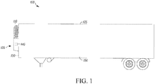
- Fig. 1 illustrates a side view of a TRS 100 for a transport unit 125, according to an embodiment.
- the illustrated transport unit 125 is a trailer-type transport unit.
- Embodiments as described in this specification can be used with other types of transport units.
- the transport unit 125 can represent a container (e.g., a container on a flat car, an intermodal container, etc.), a truck, a boxcar, or other similar type of refrigerated transport unit including an environmentally controlled interior space.
- the TRS 100 is configured to control one or more environmental conditions such as, but not limited to, temperature, humidity, and/or air quality of an interior space 150 of the transport unit 125.
- the interior space 150 can alternatively be referred to as the conditioned space 150, the cargo space 150, the environmentally controlled space 150, or the like.
- the TRS 100 is configured to transfer heat between the air inside the interior space 150 and the ambient air outside of the transport unit 125.
- the interior space 150 can include one or more partitions or internal walls (not shown) for at least partially dividing the interior space 150 into a plurality of zones or compartments, according to an embodiment. It is to be appreciated that the interior space 150 may be divided into any number of zones and in any configuration that is suitable for refrigeration of the different zones. In some examples, each of the zones can have a set point temperature that is the same or different from one another.
- the TRS 100 includes a transport refrigeration unit (TRU) 110.
- the TRU 110 is provided on a front wall 130 of the transport unit 125.
- the TRU 110 can include a prime mover (e.g., an internal combustion engine) (not shown) that provides power to a component (e.g., a compressor, etc.) of the TRS 100.
- a prime mover e.g., an internal combustion engine
- a component e.g., a compressor, etc.
- the TRU 110 includes a programmable TRS Controller 135 that includes a single integrated control unit 140.
- the TRS controller 135 may include a distributed network of TRS control elements (not shown). The number of distributed control elements in a given network can depend upon the particular application of the principles described in this specification.
- the TRS Controller 135 can include a processor, a memory, a clock, and an input/output (I/O) interface (not shown).
- the TRS Controller 135 can include fewer or additional components.
- the TRU 110 also includes a heat transfer circuit (as shown and described in Fig. 2 ).
- the TRS Controller 135 is configured to control a heat transfer cycle (e.g., controlling the heat transfer circuit of the TRU 110) of the TRS 100.
- the TRS Controller 135 controls the heat transfer cycle of the TRS 100 to obtain various operating conditions (e.g., temperature, humidity, air quality etc.) of the interior space 150.
- Fig. 2 is a schematic diagram of a heat transfer system 200 for a TRS (e.g., the TRS 100 of Fig. 1 ), according to an embodiment.
- the heat transfer system 200 includes a first heat transfer circuit 205 and a second heat transfer circuit 210.
- the first heat transfer circuit 205 can alternatively be referred to as the primary heat transfer circuit 205, the high side heat transfer circuit 205, the condensing side heat transfer circuit 205, the stage two heat transfer circuit, or the like.
- the second heat transfer circuit 210 can alternatively be referred to as the low side heat transfer circuit 210, the evaporating side heat transfer circuit 210, or the like.
- the first heat transfer circuit 205 is in thermal communication with the second heat transfer circuit 210.
- the first heat transfer circuit 205 includes a compressor 220, a condenser 230, a condenser fan 235, a first accumulator 240, a heat exchanger 245, an expansion device 250, a cascade heat exchanger 255, and a second accumulator 260.
- the compressor 220, condenser 230, first accumulator 240, heat exchanger 245, expansion device 250, cascade heat exchanger 255, and second accumulator 260 are fluidly connected to form the first heat transfer circuit 205 in which a heat transfer fluid can circulate therethrough.
- the heat transfer fluid can generally be a heat transfer fluid having a relatively low global warming potential (GWP).
- suitable heat transfer fluids for the first heat transfer circuit 205 can include, but are not limited to, hydrofluoroolefins (HFOs), hydrocarbons (HCs), and carbon dioxide (CO 2 ) (also known by its ASHRAE Standard 34 designation R-744), or the like.
- HFOs hydrofluoroolefins
- HCs hydrocarbons
- CO 2 carbon dioxide
- the compressor 220 is driven by a power source 215.
- the power source 215 can be, for example, a part of the TRU 110 ( Fig. 1 ).
- the power source 215 e.g., an internal combustion engine, an electric drive motor, etc.
- the power source 215 can also provide mechanical power directly to a generator (e.g., an alternator, etc.), which can be used to provide power either to the compressor 220 or a second compressor 275 of the second heat transfer circuit 210.
- the power source 215 may include a converter between the generator and the second compressor 275 to provide an appropriate power source for the second compressor 275.
- the power source 215 includes an electric drive motor that provides mechanical power directly to the compressor 220 and/or the second compressor 275
- the electric power can come from any of a variety of sources (e.g., batteries, shore power, etc.).
- the second heat transfer circuit 210 includes the second compressor 275, the cascade heat exchanger 255, a third accumulator 280, a second expansion device 285, an evaporator 290, and an evaporator fan 295.
- the second compressor 275, cascade heat exchanger 255, third accumulator 280, second expansion device 285, and evaporator 290 are fluidly connected to form the second heat transfer circuit 210 in which a heat transfer fluid can circulate therethrough.
- the heat transfer fluid in the second heat transfer circuit 210 can generally be different from the heat transfer fluid in the first heat transfer circuit 205.
- the heat transfer fluid in the second heat transfer circuit 210 can be, for example, R-744 (CO 2 ).
- the heat transfer fluid in the second heat transfer circuit 210 can be selected, for example, based on its performance at relatively low temperatures.
- the heat transfer system 200 can be used to maintain a desired condition in the interior space 150 of the transport unit 125. More particularly, the first heat transfer circuit 205 may receive heat that is rejected from the second heat transfer circuit 210 via the cascade heat exchanger 255. The second heat transfer circuit 210 can in turn be used to maintain the desired condition within the interior space 150.
- the first heat transfer circuit 205 can function according to generally known principles in order to remove heat from the second heat transfer circuit 210.
- the compressor 220 compresses the heat transfer fluid from a relatively lower pressure gas to a relatively higher-pressure gas.
- the relatively higher-pressure gas is discharged from the compressor 220 and flows through the condenser 230.
- the heat transfer fluid flows through the condenser 230 and rejects heat to a heat transfer fluid or medium (e.g., air, etc.), thereby cooling the heat transfer fluid or medium.
- the condenser fan 235 in accordance with generally known principles, can aid in removing the heat from the heat transfer fluid in the first heat transfer circuit 205.
- the cooled heat transfer medium which is now in a liquid form flows through the heat exchanger 245 where the heat transfer fluid is further sub-cooled prior to entering the expansion device 250.
- the heat exchanger 245 may alternatively be referred to as the suction-to-liquid line heat exchanger 245.
- the heat exchanger 245 can further sub-cool the heat transfer fluid which can, in an embodiment, increase a capacity of the first heat transfer circuit 205.
- the heat transfer medium in the first heat transfer circuit 205 absorbs heat from the heat transfer medium of the second heat transfer circuit 210, heating the heat transfer fluid and converting it to a gaseous form.
- the gaseous heat transfer fluid then flows through the second accumulator 260 and returns to the compressor 220.
- the above-described process can continue while the heat transfer circuit 205 is operating (e.g., when the prime mover 215 is operating).
- the cascade heat exchanger 255 and the heat exchange relationship between the first heat transfer circuit 205 and the second heat transfer circuit 210 can increase an efficiency of the refrigeration system by, for example, reducing an amount of energy input via the power source 215 to maintain the one or more desired conditions inside the transport unit 125 ( Fig. 1 ).
- the reduction in energy input can, for example, reduce an impact on the environment.
- the cascade heat exchanger 255 can reduce use of high pressure refrigeration components (e.g., by enabling use of lower pressure heat transfer fluids).
- the second heat transfer circuit 210 can function according to generally known principles in order to reject heat to the first heat transfer circuit 205.
- the second compressor 275 compresses the heat transfer fluid from a relatively lower pressure gas to a relatively higher-pressure gas.
- the relatively higher-pressure gas is discharged from the second compressor 275 and flows through the cascade heat exchanger 255.
- the heat transfer fluid can be in a heat exchange relationship with the heat transfer fluid of the first heat transfer circuit 205 condenser 230 and can reject heat to the heat transfer fluid of the first heat transfer circuit 205, thereby cooling the heat transfer fluid of the second heat transfer circuit 210.
- the cooled heat transfer medium which is now in a liquid form can flow through the third accumulator 280 to the second expansion device 285.
- the heat transfer fluid which is now in a mixed liquid and gaseous form, can flow to the evaporator 290.
- the heat transfer medium in the second heat transfer circuit 210 can absorb heat from a heat transfer medium (e.g., air), heating the heat transfer fluid and converting it to a gaseous form.
- the evaporator fan 295 in accordance with generally known principles, can aid in absorbing the heat from the heat transfer fluid in the second heat transfer circuit 210.
- the evaporator fan 295 can also, for example, blow air into the conditioned space 150 in order to maintain the desired condition.
- the gaseous heat transfer fluid can then return to the compressor 220. The above-described process can continue while the heat transfer circuit 210 is operating.
- Fig. 3A is a schematic diagram of a heat transfer circuit 300 which can be included in place of the heat transfer circuit 210 ( Fig. 2 ) in the heat transfer system 200 ( Fig. 2 ), according to an embodiment.
- the heat transfer circuit 300 additionally includes a flow control device 305.
- the flow control device 305 can be, for example, a four-way valve, or the like.
- the flow control device 305 can be used to modify the flow of the heat transfer fluid in the heat transfer circuit 300. This can, for example, enable the heat transfer circuit to be used in a cooling mode (e.g., the second heat transfer circuit 210 as described in accordance with Fig. 2 above) or in a heating mode, in which the flow of the heat transfer fluid is reversed in order to reject heat to the conditioned space 150 ( Fig. 1 ) instead of rejecting heat from the conditioned space 150.
- a cooling mode e.g., the second heat transfer circuit 210 as described in accordance with Fig. 2 above
- a heating mode in
- Fig. 3B is a schematic diagram of a heat transfer circuit 310 which can be included in place of the heat transfer circuit 210 ( Fig. 2 ) in the heat transfer system 200 ( Fig. 2 ), according to an embodiment.
- the heat transfer circuit 310 additionally includes a hot-gas bypass flow 315 and a flow control device 320.
- the hot-gas bypass flow 315 can be used, for example, to divert a portion of heat transfer fluid to defrost the evaporator 290.
- the flow control device 320 can be, for example, a solenoid valve (or similar type of valve) which either enables or disables flow of the heat transfer fluid.
- the flow control device 320 can have one or more intermediate positions in which flow of the heat transfer fluid therethrough is partially enabled.
- Fig. 4A is a schematic diagram of a heat transfer system 400A for a TRS (e.g., the TRS 100 of Fig. 1 ), according to an embodiment.
- the heat transfer system 400A includes a first heat transfer circuit 405A and a second heat transfer circuit 410A.
- the first heat transfer circuit 405A can alternatively be referred to as the primary heat transfer circuit 405A, the high side heat transfer circuit 405A, the condensing side heat transfer circuit 405A, the stage two heat transfer circuit 405A, or the like.
- the second heat transfer circuit 410A can alternatively be referred to as the low side heat transfer circuit 410A, the evaporating side heat transfer circuit 410A, or the like.
- the first heat transfer circuit 405A is in thermal communication with the second heat transfer circuit 410A. Aspects of the heat transfer circuit 410A may be optional, as illustrated in dashed lines in the figure.
- aspects of the heat transfer system 400A may be the same as or similar to aspects of the heat transfer system 200 of Fig. 2 .
- the first heat transfer circuit 405A includes a compressor 415A, a condenser 420A, an expansion device 425A, and a cascade heat exchanger 430A. It will be appreciated that the first heat transfer circuit 405A can include one or more additional components. For example, the first heat transfer circuit 405A can include one or more of the components shown and described in accordance with Fig. 4B below.
- the compressor 415A, condenser 420A, expansion device 425A, and cascade heat exchanger 430A are fluidly connected to form the first heat transfer circuit 405A in which a heat transfer fluid can circulate therethrough.
- the heat transfer fluid can generally be a heat transfer fluid having a relatively low global warming potential (GWP).
- suitable heat transfer fluids for the first heat transfer circuit 405A can include, but are not limited to, hydrofluoroolefins (HFOs), hydrocarbons (HCs), and carbon dioxide (CO 2 ) (also known by its ASHRAE Standard 34 designation R-744), or the like.
- the second heat transfer circuit 410A includes a compressor 435A, an expansion device 440A, and an evaporator 445A.
- the compressor 435A, cascade heat exchanger 430A, expansion device 440A, and evaporator 445A are fluidly connected to form the second heat transfer circuit 410A in which a heat transfer fluid can circulate therethrough.
- the heat transfer fluid can generally be a heat transfer fluid having a relatively low global warming potential (GWP).
- suitable heat transfer fluids for the second heat transfer circuit 410A can include, but are not limited to, hydrofluoroolefins (HFOs), hydrocarbons (HCs), and carbon dioxide (CO 2 ) (also known by its ASHRAE Standard 34 designation R-744), or the like.
- the heat transfer fluid in the first heat transfer circuit 405A and the heat transfer fluid for the second heat transfer circuit 410A can be the same. In an embodiment, the heat transfer fluid in the first heat transfer circuit 405A and the heat transfer fluid for the second heat transfer circuit 410A can be different.
- the second heat transfer circuit 410A can include one or more additional components.
- the second heat transfer circuit 410A includes one or more of an intercooler 450A, a suction-liquid heat exchanger 455A, an expansion device 460A, and an economizer 465A.
- the economizer 465A can include an economizer heat exchanger.
- the economizer 465A can include a flash tank economizer.
- a location of the suction-liquid heat exchanger 455A and the economizer 465A can be switched. That is, in the illustrated embodiment, the suction-liquid heat exchanger 455A is disposed between the economizer 465A and the cascade heat exchanger 430A. In an embodiment, the economizer 465A can be disposed between the suction-liquid heat exchanger 455A and the cascade heat exchanger 430A.
- the one or more additional components can, for example, increase an efficiency of the heat transfer system 400A. In an embodiment, the one or more additional components can, for example, reduce a size of the cascade heat exchanger 430A.
- the compressors 415A and 435A can be driven by a power source (e.g., the power source 215 in Fig. 2 ) (not shown in Fig. 4A ).
- a power source e.g., the power source 215 in Fig. 2
- the heat transfer system 400A can be used to maintain a desired condition in the interior space 150 of the transport unit 125. More particularly, the first heat transfer circuit 405A may receive heat that is rejected from the second heat transfer circuit 410A via the cascade heat exchanger 430A. The second heat transfer circuit 410A can in turn be used to maintain the desired condition within the interior space 150.
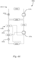
- Fig. 4B is a schematic diagram of a heat transfer system 400B for a TRS (e.g., the TRS 100 of Fig. 1 ), according to an embodiment.
- the heat transfer system 400B includes a first heat transfer circuit 405B and a second heat transfer circuit 410B.
- the first heat transfer circuit 405B can alternatively be referred to as the primary heat transfer circuit 405B, the high side heat transfer circuit 405B, the condensing side heat transfer circuit 405B, the stage two heat transfer circuit 405B, or the like.
- the second heat transfer circuit 410B can alternatively be referred to as the low side heat transfer circuit 410B, the evaporating side heat transfer circuit 410B, or the like.
- the first heat transfer circuit 405B is in thermal communication with the second heat transfer circuit 410B. Aspects of the heat transfer circuit 405B may be optional, as illustrated in dashed lines in the figure.
- aspects of the heat transfer system 400B may be the same as or similar to aspects of the heat transfer system 200 of Fig. 2 .
- the first heat transfer circuit 405B includes a compressor 415B, a condenser 420B, an expansion device 425B, and a cascade heat exchanger 430B.
- the compressor 415B, condenser 420B, expansion device 425B, and cascade heat exchanger 430B are fluidly connected to form the first heat transfer circuit 405B in which a heat transfer fluid can circulate therethrough.
- the heat transfer fluid can generally be a heat transfer fluid having a relatively low global warming potential (GWP).
- suitable heat transfer fluids for the first heat transfer circuit 405B can include, but are not limited to, hydrofluoroolefins (HFOs), hydrocarbons (HCs), and carbon dioxide (CO 2 ) (also known by its ASHRAE Standard 34 designation R-744), or the like.
- the first heat transfer circuit 405B can include one or more additional components.
- the first heat transfer circuit 405B includes one or more of a suction-liquid heat exchanger 470B, an economizer 475B, and an expansion device 480B.
- the economizer 475B can include an economizer heat exchanger.
- the economizer 475B can include a flash tank economizer.
- the one or more additional components can, for example, increase an efficiency of the first heat transfer circuit 405B, and accordingly, the heat transfer system 400B.
- the second heat transfer circuit 410B includes a compressor 435B, an expansion device 440B, and an evaporator 445B. It will be appreciated that the second heat transfer circuit 410B can include one or more additional components. For example, the second heat transfer circuit 410B can include one or more of the components shown and described in accordance with Fig. 4A above.
- the compressor 435B, cascade heat exchanger 430B, expansion device 440B, and evaporator 445B are fluidly connected to form the second heat transfer circuit 410B in which a heat transfer fluid can circulate therethrough.
- the heat transfer fluid can generally be a heat transfer fluid having a relatively low global warming potential (GWP).
- suitable heat transfer fluids for the second heat transfer circuit 410B can include, but are not limited to, hydrofluoroolefins (HFOs), hydrocarbons (HCs), and carbon dioxide (CO 2 ) (also known by its ASHRAE Standard 34 designation R-744), or the like.
- the heat transfer fluid in the first heat transfer circuit 405B and the heat transfer fluid for the second heat transfer circuit 410B can be the same.
- the heat transfer fluid in the first heat transfer circuit 405B and the heat transfer fluid for the second heat transfer circuit 410B can be different.
- the compressors 415B, 435B can be driven by a power source (e.g., the power source 215 in Fig. 2 ) (not shown in Fig. 4B ).
- a power source e.g., the power source 215 in Fig. 2
- the heat transfer system 400B can be used to maintain a desired condition in the interior space 150 of the transport unit 125. More particularly, the first heat transfer circuit 405B may receive heat that is rejected from the second heat transfer circuit 410B via the cascade heat exchanger 430B. The second heat transfer circuit 410B can in turn be used to maintain the desired condition within the interior space 150.
- a heat transfer system can include the first heat transfer circuit 405A and the second heat transfer circuit 410B.
- a heat transfer system can include the first heat transfer circuit 405B and the second heat transfer circuit 410A.
- any one of aspects 1 - 12 below can be combined with any one of aspects 13 - 23, 24 - 26, and/or 27 - 28.
- Any one of aspects 13 - 23 can be combined with any one of aspects 24 - 26 and/or 27 - 28.
- Any one of aspects 24 - 26 can be combined with any one of aspects 27 - 28.
Landscapes
- Engineering & Computer Science (AREA)
- Physics & Mathematics (AREA)
- Mechanical Engineering (AREA)
- Thermal Sciences (AREA)
- General Engineering & Computer Science (AREA)
- Chemical & Material Sciences (AREA)
- Chemical Kinetics & Catalysis (AREA)
- Analytical Chemistry (AREA)
- Power Engineering (AREA)
- Other Air-Conditioning Systems (AREA)
- Devices That Are Associated With Refrigeration Equipment (AREA)
Abstract
Description
- This disclosure relates generally to a transport refrigeration system (TRS). More specifically, the disclosure relates to systems and methods for providing a cascade heat exchange between a plurality of heat transfer circuits in a TRS.
- A transport refrigeration system (TRS) is generally used to control one or more environmental conditions such as, but not limited to, temperature, humidity, and/or air quality of a transport unit. Examples of transport units include, but are not limited to, a container (e.g., a container on a flat car, an intermodal container, etc.), a truck, a boxcar, or other similar transport units. A refrigerated transport unit is commonly used to transport perishable items such as produce, frozen foods, and meat products. Generally, the refrigerated transport unit includes a transport unit and a TRS. The TRS includes a transport refrigeration unit (TRU) that is attached to the transport unit to control one or more environmental conditions (e.g., temperature, humidity, etc.) of a particular space (e.g., a cargo space, a passenger space, etc.) (generally referred to as a "conditioned space"). The TRU can include, without limitation, a compressor, a condenser, an expansion device, an evaporator, and one or more fans or blowers to control the heat exchange between the air inside the conditioned space and the ambient air outside of the refrigerated transport unit.
- This disclosure relates generally to a transport refrigeration system (TRS). More specifically, the disclosure relates to systems and methods for providing a cascade heat exchange between a plurality of heat transfer circuits in a TRS.
- In an embodiment, the TRS includes a first heat transfer circuit and a second heat transfer circuit in thermal communication. In an embodiment the first heat transfer circuit includes a relatively low global warming potential (GWP) heat transfer fluid and the second heat transfer circuit includes a heat transfer fluid that is carbon dioxide (CO2, also referred to as R-744).
- In an embodiment, a heat transfer fluid having a relatively low GWP includes, but is not limited to, unsaturated hydrofluorocarbons (HFCs) such as hydrofluoroolefins (HFOs), hydrocarbons (HCs), ammonia, and carbon dioxide (R-744).
- A transport refrigeration system (TRS) is described. The TRS includes a first heat transfer circuit including a first compressor, a condenser, a first expansion device, and a cascade heat exchanger. The first compressor, the condenser, the first expansion device, and the cascade heat exchanger are in fluid communication such that a first heat transfer fluid can flow therethrough. The TRS includes a second heat transfer circuit including a second compressor, the cascade heat exchanger, a second expansion device, and an evaporator. The second compressor, the cascade heat exchanger, the second expansion device, and the evaporator are in fluid communication such that a second heat transfer fluid can flow therethrough. The first heat transfer circuit and the second heat transfer circuit are arranged in thermal communication at the cascade heat exchanger such that the first heat transfer fluid and the second heat transfer fluid are in a heat exchange relationship at the cascade heat exchanger.
- A system is also disclosed. The system includes an internal combustion engine; a first heat transfer circuit, and a second heat transfer circuit. The first heat transfer circuit includes a first compressor, a condenser, a first expansion device, and a cascade heat exchanger, wherein the first compressor, the condenser, the first expansion device, and the cascade heat exchanger are in fluid communication such that a first heat transfer fluid can flow therethrough. The second heat transfer circuit includes a second compressor, the cascade heat exchanger, a second expansion device, and an evaporator, wherein the second compressor, the cascade heat exchanger, the second expansion device, and the evaporator are in fluid communication such that a second heat transfer fluid can flow therethrough. The first heat transfer circuit and the second heat transfer circuit are arranged in thermal communication at the cascade heat exchanger such that the first heat transfer fluid and the second heat transfer fluid are in a heat exchange relationship at the cascade heat exchanger.
- A method of heat transfer in a transport refrigeration system (TRS) is also disclosed. The method includes providing a first heat transfer circuit including a first compressor, a condenser, a first expansion device, and a cascade heat exchanger, wherein the first compressor, the condenser, the first expansion device, and the cascade heat exchanger are in fluid communication such that a first heat transfer fluid can flow therethrough, and a second heat transfer circuit, including a second compressor, the cascade heat exchanger, a second expansion device, and an evaporator, wherein the second compressor, the cascade heat exchanger, the second expansion device, and the evaporator are in fluid communication such that a second heat transfer fluid can flow therethrough. The method further includes disposing the first heat transfer circuit and the second heat transfer circuit in thermal communication at the cascade heat exchanger such that the first heat transfer fluid and the second heat transfer fluid are in a heat exchange relationship at the cascade heat exchanger.
- References are made to the accompanying drawings that form a part of this disclosure, and which illustrate embodiments in which the systems and methods described in this specification can be practiced.
-
Fig. 1 illustrates a side view of a refrigerated transport unit, according to an embodiment. -
Fig. 2 is a schematic diagram of a heat transfer system for a transport refrigeration system, according to an embodiment. -
Fig. 3A is a schematic diagram of a reverse cycle heating/defrost circuit for the heat transfer system ofFig. 2 for a transport refrigeration system, according to an embodiment. -
Fig. 3B is a schematic diagram of a hot gas bypass heating/defrost circuit for the heat transfer system ofFig. 2 for a transport refrigeration system, according to an embodiment. -
Fig. 4A is a schematic diagram of a heat transfer system for a transport refrigeration system, according to an embodiment. -
Fig. 4B is a schematic diagram of a heat transfer system for a transport refrigeration system, according to an embodiment. - Like reference numbers represent like parts throughout.
- This disclosure relates generally to a transport refrigeration system (TRS). More specifically, the disclosure relates to systems and methods for providing a cascade heat exchange between a plurality of heat transfer circuits in a TRS.
- A TRS is generally used to control one or more environmental conditions such as, but not limited to, temperature, humidity, and/or air quality of a transport unit. Examples of transport units include, but are not limited to, a container (e.g., a container on a flat car, an intermodal container, etc.), a truck, a boxcar, or other similar transport units. A refrigerated transport unit (e.g., a transport unit including a TRS) can be used to transport perishable items such as, but not limited to, produce, frozen foods, and meat products.
- As disclosed in this specification, a TRS can include a transport refrigeration unit (TRU) which is attached to a transport unit to control one or more environmental conditions (e.g., temperature, humidity, air quality, etc.) of an interior space of the refrigerated transport unit. The TRU can include, without limitation, a compressor, a condenser, an expansion valve, an evaporator, and one or more fans or blowers to control the heat exchange between the air within the interior space and the ambient air outside of the refrigerated transport unit.
- A "transport unit" includes, for example, a container (e.g., a container on a flat car, an intermodal container, etc.), truck, a boxcar, or other similar transport unit.
- A "transport refrigeration system" (TRS) includes, for example, a refrigeration system for controlling the refrigeration of an interior space of a refrigerated transport unit. The TRS may include a vapor-compressor type refrigeration system, a thermal accumulator type system, or any other suitable refrigeration system that can use refrigerant, cold plate technology, or the like.
- A "refrigerated transport unit" includes, for example, a transport unit having a TRS.
- Embodiments of this disclosure may be used in any suitable environmentally controlled transport apparatus, such as, but not limited to, a shipboard container, an air cargo cabin, and an over the road truck cabin.
- Generally, a TRS may use hydrofluorocarbon (HFC) heat transfer fluids (commonly referred to as a "refrigerant"). For example, one commonly used HFC heat transfer fluid is R-404A (as identified according to its American Society of Heating, Refrigerating, and Air Conditioning Engineers ("ASHRAE") designation). The R-404A heat transfer fluid, however, has a relatively high global warming potential (GWP). The GWP of R-404A is 3,922 (on the 100 year GWP time horizon, according to the Intergovernmental Panel on Climate Change (IPCC Report 4)).
- An increasing focus is being placed on replacing the HFC heat transfer fluids with relatively lower GWP alternatives. Examples of suitable alternatives include, but are not limited to, unsaturated HFCs such as hydrofluoroolefins (HFOs), hydrocarbons (HCs), ammonia, and carbon dioxide (CO2, also known by its ASHRAE designation of R-744). Carbon dioxide, for example, has a GWP of 1. These alternatives have a variety of advantages and disadvantages such as, for example, safety risks (e.g., flammability, operating pressure, etc.), thermophysical properties (e.g., relating to efficiency of the TRS), cost, availability, or the like. In general, embodiments described herein can reduce global warming impact due to emissions of the heat transfer fluid into the environment, optimize efficiency of the TRS and reduce an amount of energy input to maintain a desired condition in a conditioned space, or the like.
-
Fig. 1 illustrates a side view of aTRS 100 for atransport unit 125, according to an embodiment. The illustratedtransport unit 125 is a trailer-type transport unit. Embodiments as described in this specification can be used with other types of transport units. For example, thetransport unit 125 can represent a container (e.g., a container on a flat car, an intermodal container, etc.), a truck, a boxcar, or other similar type of refrigerated transport unit including an environmentally controlled interior space. - The
TRS 100 is configured to control one or more environmental conditions such as, but not limited to, temperature, humidity, and/or air quality of aninterior space 150 of thetransport unit 125. In an embodiment, theinterior space 150 can alternatively be referred to as the conditionedspace 150, thecargo space 150, the environmentally controlledspace 150, or the like. In particular, theTRS 100 is configured to transfer heat between the air inside theinterior space 150 and the ambient air outside of thetransport unit 125. - The
interior space 150 can include one or more partitions or internal walls (not shown) for at least partially dividing theinterior space 150 into a plurality of zones or compartments, according to an embodiment. It is to be appreciated that theinterior space 150 may be divided into any number of zones and in any configuration that is suitable for refrigeration of the different zones. In some examples, each of the zones can have a set point temperature that is the same or different from one another. - The
TRS 100 includes a transport refrigeration unit (TRU) 110. TheTRU 110 is provided on afront wall 130 of thetransport unit 125. TheTRU 110 can include a prime mover (e.g., an internal combustion engine) (not shown) that provides power to a component (e.g., a compressor, etc.) of theTRS 100. - The
TRU 110 includes aprogrammable TRS Controller 135 that includes a singleintegrated control unit 140. It is to be appreciated that, in an embodiment, TheTRS controller 135 may include a distributed network of TRS control elements (not shown). The number of distributed control elements in a given network can depend upon the particular application of the principles described in this specification. TheTRS Controller 135 can include a processor, a memory, a clock, and an input/output (I/O) interface (not shown). TheTRS Controller 135 can include fewer or additional components. - The
TRU 110 also includes a heat transfer circuit (as shown and described inFig. 2 ). Generally, theTRS Controller 135 is configured to control a heat transfer cycle (e.g., controlling the heat transfer circuit of the TRU 110) of theTRS 100. In one example, theTRS Controller 135 controls the heat transfer cycle of theTRS 100 to obtain various operating conditions (e.g., temperature, humidity, air quality etc.) of theinterior space 150. -
Fig. 2 is a schematic diagram of aheat transfer system 200 for a TRS (e.g., theTRS 100 ofFig. 1 ), according to an embodiment. Theheat transfer system 200 includes a firstheat transfer circuit 205 and a secondheat transfer circuit 210. In an embodiment, the firstheat transfer circuit 205 can alternatively be referred to as the primaryheat transfer circuit 205, the high sideheat transfer circuit 205, the condensing sideheat transfer circuit 205, the stage two heat transfer circuit, or the like. In an embodiment, the secondheat transfer circuit 210 can alternatively be referred to as the low sideheat transfer circuit 210, the evaporating sideheat transfer circuit 210, or the like. The firstheat transfer circuit 205 is in thermal communication with the secondheat transfer circuit 210. - The first
heat transfer circuit 205 includes acompressor 220, acondenser 230, acondenser fan 235, afirst accumulator 240, aheat exchanger 245, anexpansion device 250, acascade heat exchanger 255, and asecond accumulator 260. Thecompressor 220,condenser 230,first accumulator 240,heat exchanger 245,expansion device 250,cascade heat exchanger 255, andsecond accumulator 260 are fluidly connected to form the firstheat transfer circuit 205 in which a heat transfer fluid can circulate therethrough. The heat transfer fluid can generally be a heat transfer fluid having a relatively low global warming potential (GWP). Examples of suitable heat transfer fluids for the firstheat transfer circuit 205 can include, but are not limited to, hydrofluoroolefins (HFOs), hydrocarbons (HCs), and carbon dioxide (CO2) (also known by its ASHRAE Standard 34 designation R-744), or the like. - In the illustrated embodiment, the
compressor 220 is driven by apower source 215. Thepower source 215 can be, for example, a part of the TRU 110 (Fig. 1 ). The power source 215 (e.g., an internal combustion engine, an electric drive motor, etc.) can provide mechanical power directly to thecompressor 220. Thepower source 215 can also provide mechanical power directly to a generator (e.g., an alternator, etc.), which can be used to provide power either to thecompressor 220 or asecond compressor 275 of the secondheat transfer circuit 210. In such an embodiment, thepower source 215 may include a converter between the generator and thesecond compressor 275 to provide an appropriate power source for thesecond compressor 275. In an embodiment in which thepower source 215 includes an electric drive motor that provides mechanical power directly to thecompressor 220 and/or thesecond compressor 275, the electric power can come from any of a variety of sources (e.g., batteries, shore power, etc.). - The second
heat transfer circuit 210 includes thesecond compressor 275, thecascade heat exchanger 255, athird accumulator 280, asecond expansion device 285, anevaporator 290, and anevaporator fan 295. Thesecond compressor 275,cascade heat exchanger 255,third accumulator 280,second expansion device 285, andevaporator 290 are fluidly connected to form the secondheat transfer circuit 210 in which a heat transfer fluid can circulate therethrough. The heat transfer fluid in the secondheat transfer circuit 210 can generally be different from the heat transfer fluid in the firstheat transfer circuit 205. The heat transfer fluid in the secondheat transfer circuit 210 can be, for example, R-744 (CO2). The heat transfer fluid in the secondheat transfer circuit 210 can be selected, for example, based on its performance at relatively low temperatures. - In operation, the
heat transfer system 200 can be used to maintain a desired condition in theinterior space 150 of thetransport unit 125. More particularly, the firstheat transfer circuit 205 may receive heat that is rejected from the secondheat transfer circuit 210 via thecascade heat exchanger 255. The secondheat transfer circuit 210 can in turn be used to maintain the desired condition within theinterior space 150. - The first
heat transfer circuit 205 can function according to generally known principles in order to remove heat from the secondheat transfer circuit 210. Thecompressor 220 compresses the heat transfer fluid from a relatively lower pressure gas to a relatively higher-pressure gas. The relatively higher-pressure gas is discharged from thecompressor 220 and flows through thecondenser 230. In accordance with generally known principles, the heat transfer fluid flows through thecondenser 230 and rejects heat to a heat transfer fluid or medium (e.g., air, etc.), thereby cooling the heat transfer fluid or medium. Thecondenser fan 235, in accordance with generally known principles, can aid in removing the heat from the heat transfer fluid in the firstheat transfer circuit 205. The cooled heat transfer medium which is now in a liquid form flows through theheat exchanger 245 where the heat transfer fluid is further sub-cooled prior to entering theexpansion device 250. Theheat exchanger 245 may alternatively be referred to as the suction-to-liquidline heat exchanger 245. Theheat exchanger 245 can further sub-cool the heat transfer fluid which can, in an embodiment, increase a capacity of the firstheat transfer circuit 205. The heat transfer fluid, in a mixed liquid and gaseous form, flows to thecascade heat exchanger 255. - At the
cascade heat exchanger 255, the heat transfer medium in the firstheat transfer circuit 205 absorbs heat from the heat transfer medium of the secondheat transfer circuit 210, heating the heat transfer fluid and converting it to a gaseous form. The gaseous heat transfer fluid then flows through thesecond accumulator 260 and returns to thecompressor 220. The above-described process can continue while theheat transfer circuit 205 is operating (e.g., when theprime mover 215 is operating). In an embodiment, thecascade heat exchanger 255 and the heat exchange relationship between the firstheat transfer circuit 205 and the secondheat transfer circuit 210 can increase an efficiency of the refrigeration system by, for example, reducing an amount of energy input via thepower source 215 to maintain the one or more desired conditions inside the transport unit 125 (Fig. 1 ). In an embodiment, the reduction in energy input can, for example, reduce an impact on the environment. In an embodiment, thecascade heat exchanger 255 can reduce use of high pressure refrigeration components (e.g., by enabling use of lower pressure heat transfer fluids). - The second
heat transfer circuit 210 can function according to generally known principles in order to reject heat to the firstheat transfer circuit 205. Thesecond compressor 275 compresses the heat transfer fluid from a relatively lower pressure gas to a relatively higher-pressure gas. The relatively higher-pressure gas is discharged from thesecond compressor 275 and flows through thecascade heat exchanger 255. In accordance with generally known principles, the heat transfer fluid can be in a heat exchange relationship with the heat transfer fluid of the firstheat transfer circuit 205condenser 230 and can reject heat to the heat transfer fluid of the firstheat transfer circuit 205, thereby cooling the heat transfer fluid of the secondheat transfer circuit 210. The cooled heat transfer medium which is now in a liquid form can flow through thethird accumulator 280 to thesecond expansion device 285. As a result, a portion of the heat transfer fluid is converted to a gaseous form. The heat transfer fluid, which is now in a mixed liquid and gaseous form, can flow to theevaporator 290. At theevaporator 290, the heat transfer medium in the secondheat transfer circuit 210 can absorb heat from a heat transfer medium (e.g., air), heating the heat transfer fluid and converting it to a gaseous form. Theevaporator fan 295, in accordance with generally known principles, can aid in absorbing the heat from the heat transfer fluid in the secondheat transfer circuit 210. Theevaporator fan 295 can also, for example, blow air into the conditionedspace 150 in order to maintain the desired condition. The gaseous heat transfer fluid can then return to thecompressor 220. The above-described process can continue while theheat transfer circuit 210 is operating. -
Fig. 3A is a schematic diagram of aheat transfer circuit 300 which can be included in place of the heat transfer circuit 210 (Fig. 2 ) in the heat transfer system 200 (Fig. 2 ), according to an embodiment. Theheat transfer circuit 300 additionally includes aflow control device 305. Theflow control device 305 can be, for example, a four-way valve, or the like. In operation, theflow control device 305 can be used to modify the flow of the heat transfer fluid in theheat transfer circuit 300. This can, for example, enable the heat transfer circuit to be used in a cooling mode (e.g., the secondheat transfer circuit 210 as described in accordance withFig. 2 above) or in a heating mode, in which the flow of the heat transfer fluid is reversed in order to reject heat to the conditioned space 150 (Fig. 1 ) instead of rejecting heat from the conditionedspace 150. -
Fig. 3B is a schematic diagram of aheat transfer circuit 310 which can be included in place of the heat transfer circuit 210 (Fig. 2 ) in the heat transfer system 200 (Fig. 2 ), according to an embodiment. Theheat transfer circuit 310 additionally includes a hot-gas bypass flow 315 and aflow control device 320. The hot-gas bypass flow 315 can be used, for example, to divert a portion of heat transfer fluid to defrost theevaporator 290. Theflow control device 320 can be, for example, a solenoid valve (or similar type of valve) which either enables or disables flow of the heat transfer fluid. In an embodiment, theflow control device 320 can have one or more intermediate positions in which flow of the heat transfer fluid therethrough is partially enabled. -
Fig. 4A is a schematic diagram of aheat transfer system 400A for a TRS (e.g., theTRS 100 ofFig. 1 ), according to an embodiment. Theheat transfer system 400A includes a firstheat transfer circuit 405A and a secondheat transfer circuit 410A. In an embodiment, the firstheat transfer circuit 405A can alternatively be referred to as the primaryheat transfer circuit 405A, the high sideheat transfer circuit 405A, the condensing sideheat transfer circuit 405A, the stage twoheat transfer circuit 405A, or the like. In an embodiment, the secondheat transfer circuit 410A can alternatively be referred to as the low sideheat transfer circuit 410A, the evaporating sideheat transfer circuit 410A, or the like. The firstheat transfer circuit 405A is in thermal communication with the secondheat transfer circuit 410A. Aspects of theheat transfer circuit 410A may be optional, as illustrated in dashed lines in the figure. - Aspects of the
heat transfer system 400A may be the same as or similar to aspects of theheat transfer system 200 ofFig. 2 . - The first
heat transfer circuit 405A includes acompressor 415A, acondenser 420A, anexpansion device 425A, and acascade heat exchanger 430A. It will be appreciated that the firstheat transfer circuit 405A can include one or more additional components. For example, the firstheat transfer circuit 405A can include one or more of the components shown and described in accordance withFig. 4B below. - The
compressor 415A,condenser 420A,expansion device 425A, andcascade heat exchanger 430A are fluidly connected to form the firstheat transfer circuit 405A in which a heat transfer fluid can circulate therethrough. The heat transfer fluid can generally be a heat transfer fluid having a relatively low global warming potential (GWP). Examples of suitable heat transfer fluids for the firstheat transfer circuit 405A can include, but are not limited to, hydrofluoroolefins (HFOs), hydrocarbons (HCs), and carbon dioxide (CO2) (also known by its ASHRAE Standard 34 designation R-744), or the like. - The second
heat transfer circuit 410A includes acompressor 435A, anexpansion device 440A, and anevaporator 445A. Thecompressor 435A,cascade heat exchanger 430A,expansion device 440A, andevaporator 445A are fluidly connected to form the secondheat transfer circuit 410A in which a heat transfer fluid can circulate therethrough. The heat transfer fluid can generally be a heat transfer fluid having a relatively low global warming potential (GWP). Examples of suitable heat transfer fluids for the secondheat transfer circuit 410A can include, but are not limited to, hydrofluoroolefins (HFOs), hydrocarbons (HCs), and carbon dioxide (CO2) (also known by its ASHRAE Standard 34 designation R-744), or the like. In an embodiment, the heat transfer fluid in the firstheat transfer circuit 405A and the heat transfer fluid for the secondheat transfer circuit 410A can be the same. In an embodiment, the heat transfer fluid in the firstheat transfer circuit 405A and the heat transfer fluid for the secondheat transfer circuit 410A can be different. - The second
heat transfer circuit 410A can include one or more additional components. For example, in an embodiment, the secondheat transfer circuit 410A includes one or more of an intercooler 450A, a suction-liquid heat exchanger 455A, anexpansion device 460A, and aneconomizer 465A. In an embodiment, theeconomizer 465A can include an economizer heat exchanger. In an embodiment, theeconomizer 465A can include a flash tank economizer. - In an embodiment, a location of the suction-
liquid heat exchanger 455A and theeconomizer 465A can be switched. That is, in the illustrated embodiment, the suction-liquid heat exchanger 455A is disposed between theeconomizer 465A and thecascade heat exchanger 430A. In an embodiment, theeconomizer 465A can be disposed between the suction-liquid heat exchanger 455A and thecascade heat exchanger 430A. In an embodiment, the one or more additional components can, for example, increase an efficiency of theheat transfer system 400A. In an embodiment, the one or more additional components can, for example, reduce a size of thecascade heat exchanger 430A. - The
compressors power source 215 inFig. 2 ) (not shown inFig. 4A ). - In operation, the
heat transfer system 400A can be used to maintain a desired condition in theinterior space 150 of thetransport unit 125. More particularly, the firstheat transfer circuit 405A may receive heat that is rejected from the secondheat transfer circuit 410A via thecascade heat exchanger 430A. The secondheat transfer circuit 410A can in turn be used to maintain the desired condition within theinterior space 150. -
Fig. 4B is a schematic diagram of aheat transfer system 400B for a TRS (e.g., theTRS 100 ofFig. 1 ), according to an embodiment. Theheat transfer system 400B includes a firstheat transfer circuit 405B and a secondheat transfer circuit 410B. In an embodiment, the firstheat transfer circuit 405B can alternatively be referred to as the primaryheat transfer circuit 405B, the high sideheat transfer circuit 405B, the condensing sideheat transfer circuit 405B, the stage twoheat transfer circuit 405B, or the like. In an embodiment, the secondheat transfer circuit 410B can alternatively be referred to as the low sideheat transfer circuit 410B, the evaporating sideheat transfer circuit 410B, or the like. The firstheat transfer circuit 405B is in thermal communication with the secondheat transfer circuit 410B. Aspects of theheat transfer circuit 405B may be optional, as illustrated in dashed lines in the figure. - Aspects of the
heat transfer system 400B may be the same as or similar to aspects of theheat transfer system 200 ofFig. 2 . - The first
heat transfer circuit 405B includes acompressor 415B, acondenser 420B, anexpansion device 425B, and a cascade heat exchanger 430B. - The
compressor 415B,condenser 420B,expansion device 425B, and cascade heat exchanger 430B are fluidly connected to form the firstheat transfer circuit 405B in which a heat transfer fluid can circulate therethrough. The heat transfer fluid can generally be a heat transfer fluid having a relatively low global warming potential (GWP). Examples of suitable heat transfer fluids for the firstheat transfer circuit 405B can include, but are not limited to, hydrofluoroolefins (HFOs), hydrocarbons (HCs), and carbon dioxide (CO2) (also known by its ASHRAE Standard 34 designation R-744), or the like. - The first
heat transfer circuit 405B can include one or more additional components. For example, in an embodiment, the firstheat transfer circuit 405B includes one or more of a suction-liquid heat exchanger 470B, aneconomizer 475B, and anexpansion device 480B. In an embodiment, theeconomizer 475B can include an economizer heat exchanger. In an embodiment, theeconomizer 475B can include a flash tank economizer. In an embodiment, the one or more additional components can, for example, increase an efficiency of the firstheat transfer circuit 405B, and accordingly, theheat transfer system 400B. - The second
heat transfer circuit 410B includes acompressor 435B, anexpansion device 440B, and an evaporator 445B. It will be appreciated that the secondheat transfer circuit 410B can include one or more additional components. For example, the secondheat transfer circuit 410B can include one or more of the components shown and described in accordance withFig. 4A above. - The
compressor 435B, cascade heat exchanger 430B,expansion device 440B, andevaporator 445B are fluidly connected to form the secondheat transfer circuit 410B in which a heat transfer fluid can circulate therethrough. The heat transfer fluid can generally be a heat transfer fluid having a relatively low global warming potential (GWP). Examples of suitable heat transfer fluids for the secondheat transfer circuit 410B can include, but are not limited to, hydrofluoroolefins (HFOs), hydrocarbons (HCs), and carbon dioxide (CO2) (also known by its ASHRAE Standard 34 designation R-744), or the like. In an embodiment, the heat transfer fluid in the firstheat transfer circuit 405B and the heat transfer fluid for the secondheat transfer circuit 410B can be the same. In an embodiment, the heat transfer fluid in the firstheat transfer circuit 405B and the heat transfer fluid for the secondheat transfer circuit 410B can be different. - The
compressors power source 215 inFig. 2 ) (not shown inFig. 4B ). - In operation, the
heat transfer system 400B can be used to maintain a desired condition in theinterior space 150 of thetransport unit 125. More particularly, the firstheat transfer circuit 405B may receive heat that is rejected from the secondheat transfer circuit 410B via the cascade heat exchanger 430B. The secondheat transfer circuit 410B can in turn be used to maintain the desired condition within theinterior space 150. - It is to be appreciated that aspects of
Figs. 4A and4B can be combined. For example, a heat transfer system can include the firstheat transfer circuit 405A and the secondheat transfer circuit 410B. In an embodiment, a heat transfer system can include the firstheat transfer circuit 405B and the secondheat transfer circuit 410A. - It is noted that any one of aspects 1 - 12 below can be combined with any one of aspects 13 - 23, 24 - 26, and/or 27 - 28. Any one of aspects 13 - 23 can be combined with any one of aspects 24 - 26 and/or 27 - 28. Any one of aspects 24 - 26 can be combined with any one of aspects 27 - 28.
- Aspect 1. A transport refrigeration system (TRS), comprising:
- a first heat transfer circuit, including:
- a first compressor, a condenser, a first expansion device, and a cascade heat exchanger, wherein the first compressor, the condenser, the first expansion device, and the cascade heat exchanger are in fluid communication such that a first heat transfer fluid can flow therethrough; and
- a second heat transfer circuit, including:
- a second compressor, the cascade heat exchanger, a second expansion device, and an evaporator, wherein the second compressor, the cascade heat exchanger, the second expansion device, and the evaporator are in fluid communication such that a second heat transfer fluid can flow therethrough;
- wherein the first heat transfer circuit and the second heat transfer circuit are arranged in thermal communication at the cascade heat exchanger such that the first heat transfer fluid and the second heat transfer fluid are in a heat exchange relationship at the cascade heat exchanger.
- a first heat transfer circuit, including:
- Aspect 2. The TRS according to aspect 1, further comprising a prime mover configured to provide mechanical power to the first compressor.
- Aspect 3. The TRS according to aspect 2, further comprising a generator connected to the prime mover such that the prime mover provides mechanical power to the generator, wherein the generator is electrically connected to the second compressor to provide an electric power to the second compressor.
- Aspect 4. The TRS according to any one of aspects 1-3, wherein the first heat transfer fluid and the second heat transfer fluid are different.
- Aspect 5. The TRS according to any one of aspects 1-4, wherein the first heat transfer fluid has a relatively low global warming potential (GWP).
- Aspect 6. The TRS according to aspect 5, wherein the first heat transfer fluid is an unsaturated hydrofluorocarbon (HFC).
- Aspect 7. The TRS according to aspect 6, wherein the first heat transfer fluid is one of a hydrofluoroolefin (HFO), a hydrocarbon (HC), ammonia, or carbon dioxide (CO2).
- Aspect 8. The TRS according to any one of aspects 1-7, wherein the second heat transfer fluid is carbon dioxide (CO2).
- Aspect 9. The TRS according to any one of aspects 1-8, wherein the second heat transfer circuit further includes a four-way flow control device.
- Aspect 10. The TRS according to any one of aspects 1-9, wherein the second heat transfer circuit further includes a hot-gas bypass.
- Aspect 11. The TRS according to any one of aspects 1 - 10, wherein the second heat transfer circuit further includes one or more of an intercooler, a suction-liquid heat exchanger, and an economizer.
- Aspect 12. The TRS according to any one of aspects 1-11, wherein the first heat transfer circuit further includes one or more of a suction-liquid heat exchanger and an economizer.
- Aspect 13. A system, comprising:
- an internal combustion engine;
- a first heat transfer circuit, including:
- a first compressor, a condenser, a first expansion device, and a cascade heat exchanger, wherein the first compressor, the condenser, the first expansion device, and the cascade heat exchanger are in fluid communication such that a first heat transfer fluid can flow therethrough; and
- a second heat transfer circuit, including:
- a second compressor, the cascade heat exchanger, a second expansion device, and an evaporator, wherein the second compressor, the cascade heat exchanger, the second expansion device, and the evaporator are in fluid communication such that a second heat transfer fluid can flow therethrough;
- wherein the first heat transfer circuit and the second heat transfer circuit are arranged in thermal communication at the cascade heat exchanger such that the first heat transfer fluid and the second heat transfer fluid are in a heat exchange relationship at the cascade heat exchanger.
- Aspect 14. The system according to aspect 13, further comprising a generator coupled to the internal combustion engine, wherein the generator is configured to provide an electrical power to the second compressor.
- Aspect 15. The system according to any one of aspects 13 - 14, wherein the first heat transfer fluid and the second heat transfer fluid are different.
- Aspect 16. The system according to any one of aspects 13 - 15, wherein the first heat transfer fluid has a relatively low global warming potential (GWP).
- Aspect 17. The system according to aspect 16, wherein the first heat transfer fluid is an unsaturated hydrofluorocarbon (HFC).
- Aspect 18. The system according to aspect 17, wherein the first heat transfer fluid is one of a hydrofluoroolefin (HFO), a hydrocarbon (HC), ammonia, or carbon dioxide (CO2).
- Aspect 19. The system according to any one of aspects 13 - 18, wherein the second heat transfer fluid is carbon dioxide (CO2).
- Aspect 20. The system according to any one of aspects 13 - 19, wherein the second heat transfer circuit further includes a four-way flow control device.
- Aspect 21. The system according to any one of aspects 13 - 20, wherein the second heat transfer circuit further includes a hot-gas bypass.
- Aspect 22. The system according to any one of aspects 13 - 21, wherein the second heat transfer circuit further includes one or more of an intercooler, a suction-liquid heat exchanger, and an economizer.
- Aspect 23. The system according to any one of aspects 13 - 22, wherein the first heat transfer circuit further includes one or more of a suction-liquid heat exchanger and an economizer.
- Aspect 24. A method of heat transfer in a transport refrigeration system (TRS), the TRS having a first heat transfer circuit and a second heat transfer circuit in thermal communication via a cascade heat exchanger, the method comprising:
- circulating a first heat transfer fluid through the first heat transfer circuit;
- circulating a second heat transfer fluid through the second heat transfer circuit; and
- exchanging heat between the first heat transfer fluid and the second heat transfer fluid via the cascade heat exchanger.
- Aspect 25. The method according to aspect 24, wherein exchanging heat between the first heat transfer fluid and the second heat transfer fluid via the cascade heat exchanger includes rejecting heat from the second heat transfer fluid to the first heat transfer fluid.
- Aspect 26. The method according to aspect 25, wherein the second heat transfer circuit is in thermal communication with a conditioned space of the TRS, and the method further includes controlling one or more environmental conditions in the conditioned space with the second heat transfer circuit.
- Aspect 27. A transport refrigeration system (TRS), comprising:
- a first heat transfer circuit, including:
- a first compressor, a condenser, a first expansion device, an economizer, a second expansion device, and a cascade heat exchanger, wherein the first compressor, the condenser, the first expansion device, the economizer, the second expansion device, and the cascade heat exchanger are in fluid communication such that a first heat transfer fluid can flow therethrough; and
- a second heat transfer circuit, including:
- a second compressor, an intercooler, the cascade heat exchanger, a suction-liquid heat exchanger, a third expansion device, and an evaporator, wherein the second compressor, the intercooler, the cascade heat exchanger, the suction-liquid heat exchanger, the third expansion device, and the evaporator are in fluid communication such that a second heat transfer fluid can flow therethrough;
- wherein the first heat transfer circuit and the second heat transfer circuit are arranged in thermal communication at the cascade heat exchanger such that the first heat transfer fluid and the second heat transfer fluid are in a heat exchange relationship at the cascade heat exchanger.
- a first heat transfer circuit, including:
- Aspect 28. The TRS according to aspect 27, wherein the economizer is one of an economizer heat exchanger and a flash tank economizer.
- The terminology used in this specification is intended to describe particular embodiments and is not intended to be limiting. The terms "a," "an," and "the" include the plural forms as well, unless clearly indicated otherwise. The terms "comprises" and/or "comprising," when used in this specification, specify the presence of the stated features, integers, steps, operations, elements, and/or components, but do not preclude the presence or addition of one or more other features, integers, steps, operations, elements, and/or components.
- With regard to the preceding description, it is to be understood that changes may be made in detail, especially in matters of the construction materials employed and the shape, size, and arrangement of parts without departing from the scope of the present disclosure. This specification and the embodiments described are exemplary only, with the true scope and spirit of the disclosure being indicated by the claims that follow.
Claims (15)
- A transport refrigeration system (TRS), comprising:a first heat transfer circuit, including:a first compressor, a condenser, a first expansion device, and a cascade heat exchanger, wherein the first compressor, the condenser, the first expansion device, and the cascade heat exchanger are in fluid communication such that a first heat transfer fluid can flow therethrough; anda second heat transfer circuit, including:a second compressor, the cascade heat exchanger, a second expansion device, and an evaporator, wherein the second compressor, the cascade heat exchanger, the second expansion device, and the evaporator are in fluid communication such that a second heat transfer fluid can flow therethrough;wherein the first heat transfer circuit and the second heat transfer circuit are arranged in thermal communication at the cascade heat exchanger such that the first heat transfer fluid and the second heat transfer fluid are in a heat exchange relationship at the cascade heat exchanger.
- The TRS according to claim 1, further comprising a prime mover configured to provide mechanical power to the first compressor.
- The TRS according to claim 2, further comprising a generator connected to the prime mover such that the prime mover provides mechanical power to the generator, wherein the generator is electrically connected to the second compressor to provide an electric power to the second compressor.
- The TRS according to claim 1, wherein the first heat transfer fluid and the second heat transfer fluid are different.
- The TRS according to claim 1, wherein the first heat transfer fluid has a relatively low global warming potential (GWP) and is one of an unsaturated hydrofluorocarbon (HFC), a hydrofluoroolefin (HFO), a hydrocarbon (HC), ammonia, or carbon dioxide (CO2).
- The TRS according to claim 1, wherein the second heat transfer fluid is carbon dioxide (CO2).
- The TRS according to claim 1, wherein the second heat transfer circuit further includes one or more of a four-way flow control device, a hot-gas bypass, an intercooler, a suction-liquid heat exchanger, and an economizer.
- The TRS according to claim 1, wherein the first heat transfer circuit includes one or more of a suction-liquid heat exchanger and an economizer.
- A system, comprising:an internal combustion engine;a first heat transfer circuit, including:a first compressor, a condenser, a first expansion device, and a cascade heat exchanger, wherein the first compressor, the condenser, the first expansion device, and the cascade heat exchanger are in fluid communication such that a first heat transfer fluid can flow therethrough; anda second heat transfer circuit, including:a second compressor, the cascade heat exchanger, a second expansion device, and an evaporator, wherein the second compressor, the cascade heat exchanger, the second expansion device, and the evaporator are in fluid communication such that a second heat transfer fluid can flow therethrough;wherein the first heat transfer circuit and the second heat transfer circuit are arranged in thermal communication at the cascade heat exchanger such that the first heat transfer fluid and the second heat transfer fluid are in a heat exchange relationship at the cascade heat exchanger.
- The system according to claim 9, further comprising a generator coupled to the internal combustion engine, wherein the generator is configured to provide an electrical power to the second compressor.
- The system according to claim 9, wherein the first heat transfer fluid has a relatively low global warming potential (GWP) and is one of an unsaturated hydrofluorocarbon (HFC), a hydrofluoroolefin (HFO), a hydrocarbon (HC), ammonia, or carbon dioxide (CO2).
- The system according to claim 9, wherein the second heat transfer circuit further includes one or more of a four-way flow control device, a hot-gas bypass, an intercooler, a suction-liquid heat exchanger, and an economizer.
- The system according to claim 9, wherein the first heat transfer circuit further includes one or more of a suction-liquid heat exchanger and an economizer.
- A method of heat transfer in a transport refrigeration system (TRS), the TRS having a first heat transfer circuit and a second heat transfer circuit in thermal communication via a cascade heat exchanger, the method comprising:circulating a first heat transfer fluid through the first heat transfer circuit;circulating a second heat transfer fluid through the second heat transfer circuit; andexchanging heat between the first heat transfer fluid and the second heat transfer fluid via the cascade heat exchanger.
- The method according to claim 18, wherein exchanging heat between the first heat transfer fluid and the second heat transfer fluid via the cascade heat exchanger includes rejecting heat from the second heat transfer fluid to the first heat transfer fluid, wherein the second heat transfer circuit is in thermal communication with a conditioned space of the TRS, and the method further includes controlling one or more environmental conditions in the conditioned space with the second heat transfer circuit.
Applications Claiming Priority (1)
| Application Number | Priority Date | Filing Date | Title |
|---|---|---|---|
| US201562271872P | 2015-12-28 | 2015-12-28 |
Publications (1)
| Publication Number | Publication Date |
|---|---|
| EP3187796A1 true EP3187796A1 (en) | 2017-07-05 |
Family
ID=57749758
Family Applications (1)
| Application Number | Title | Priority Date | Filing Date |
|---|---|---|---|
| EP16207174.0A Pending EP3187796A1 (en) | 2015-12-28 | 2016-12-28 | Cascade heat transfer system |
Country Status (2)
| Country | Link |
|---|---|
| US (2) | US10543737B2 (en) |
| EP (1) | EP3187796A1 (en) |
Cited By (1)
| Publication number | Priority date | Publication date | Assignee | Title |
|---|---|---|---|---|
| EP3481657B1 (en) * | 2016-07-05 | 2023-05-03 | Carrier Corporation | Dual compressor transportation refrigeration unit |
Families Citing this family (27)
| Publication number | Priority date | Publication date | Assignee | Title |
|---|---|---|---|---|
| EP3452763B1 (en) * | 2016-05-03 | 2022-03-30 | Carrier Corporation | Ejector-enhanced heat recovery refrigeration system |
| US12270404B2 (en) | 2017-08-28 | 2025-04-08 | Mark J. Maynard | Gas-driven generator system comprising an elongate gravitational distribution conduit coupled with a gas injection system |
| US12049899B2 (en) * | 2017-08-28 | 2024-07-30 | Mark J. Maynard | Systems and methods for improving the performance of air-driven generators using solar thermal heating |
| CN108253650B (en) * | 2018-01-18 | 2019-04-12 | 西安交通大学 | A kind of control method of critical-cross carbon dioxide combined heat-pump system |
| AU2019209876A1 (en) * | 2018-01-18 | 2020-08-13 | Mark J. Maynard | Gaseous fluid compression with alternating refrigeration and mechanical compression |
| JP7644500B2 (en) | 2019-04-29 | 2025-03-12 | カーボンクエスト, インコーポレイテッド | Building Emissions Treatment and/or Sequestration Systems and Methods - Patent application |
| CN111907301B (en) | 2019-05-07 | 2024-10-25 | 开利公司 | Combined heat exchanger, heat exchange system and optimization method thereof |
| US11137805B2 (en) * | 2019-06-14 | 2021-10-05 | Klinge Corporation | Dual redundant cooling system for a container |
| CN110671848B (en) * | 2019-10-16 | 2021-06-15 | 佛山市纳奇电气设备有限公司 | A control system for carbon dioxide efficient refrigeration equipment |
| US12228318B2 (en) * | 2019-12-19 | 2025-02-18 | Trane Technologies Life Sciences Llc | System and method of hot gas defrost control for multistage cascade refrigeration system |
| CN111306824B (en) * | 2020-03-30 | 2024-03-19 | 宁波奥克斯电气股份有限公司 | A cascade heat pump and its control method |
| JP7492154B2 (en) | 2020-05-08 | 2024-05-29 | ダイキン工業株式会社 | Refrigeration Cycle Equipment |
| JP2021196114A (en) * | 2020-06-15 | 2021-12-27 | 三菱重工業株式会社 | Refrigeration machine for transportation, and transportation machine |
| JP2021196115A (en) * | 2020-06-15 | 2021-12-27 | 三菱重工業株式会社 | Refrigeration machine for transportation |
| JP7470581B2 (en) | 2020-06-26 | 2024-04-18 | 三菱重工業株式会社 | Transport refrigeration equipment and transport equipment |
| US11813925B2 (en) | 2020-09-28 | 2023-11-14 | Thermo King Llc | Methods and systems for maintaining cargo at an ultra-low temperature over an extended period of time |
| CN112297769B (en) * | 2020-11-05 | 2021-12-21 | 华南理工大学 | All-weather electric automobile heat pump air-conditioning system |
| WO2022118844A1 (en) * | 2020-12-01 | 2022-06-09 | ダイキン工業株式会社 | Refrigeration cycle system |
| DE102021207027A1 (en) | 2021-07-05 | 2023-01-05 | Mitsubishi Heavy Industries, Ltd. | Refrigeration machine for transport |
| US12367498B2 (en) | 2021-10-11 | 2025-07-22 | Carbonquest, Inc. | Carbon management systems and method for management of carbon use and/or production in buildings |
| CN114674095B (en) * | 2022-03-16 | 2024-04-23 | 青岛海尔空调器有限总公司 | Air conditioner, method, device and storage medium for controlling air conditioner refrigerant |
| US12435909B2 (en) | 2022-04-08 | 2025-10-07 | Mark J. Maynard | Systems and methods of using cascading heat pumps for improvement of coefficient of performance |
| JP2025515598A (en) * | 2022-04-28 | 2025-05-20 | カーボンクエスト, インコーポレイテッド | CO2 Separation System and Method |
| US12313319B2 (en) | 2022-08-12 | 2025-05-27 | Bmil Technologies, Llc | Low GWP cascade refrigeration system |
| US12313318B2 (en) * | 2022-08-12 | 2025-05-27 | Bmil Technologies, Llc | Low GWP cascade refrigeration system |
| US20240053065A1 (en) * | 2022-08-12 | 2024-02-15 | BMIL Technology, LLC | Low gwp cascade refrigeration system |
| US12491748B2 (en) * | 2023-08-01 | 2025-12-09 | Klinge Corporation | Dual redundant picture frame refrigerant system for a refrigerated container |
Citations (9)
| Publication number | Priority date | Publication date | Assignee | Title |
|---|---|---|---|---|
| US20080011007A1 (en) * | 2006-03-10 | 2008-01-17 | International Truck Intellectual Property Company, Llc | Cold plate refrigeration system optimized for energy efficiency |
| US20090272128A1 (en) * | 2008-05-02 | 2009-11-05 | Kysor Industrial Corporation | Cascade cooling system with intercycle cooling |
| EP2131122A1 (en) * | 2007-03-27 | 2009-12-09 | Mitsubishi Electric Corporation | Heat pump device |
| WO2014030238A1 (en) * | 2012-08-23 | 2014-02-27 | 三菱電機株式会社 | Refrigeration device |
| WO2014047401A1 (en) * | 2012-09-20 | 2014-03-27 | Thermo King Corporation | Electrical transport refrigeration system |
| WO2014082069A1 (en) * | 2012-11-26 | 2014-05-30 | Thermo King Corporation | Auxiliary subcooling circuit for a transport refrigeration system |
| WO2014199445A1 (en) * | 2013-06-11 | 2014-12-18 | 三菱電機株式会社 | Refrigerating device |
| DE102014200160A1 (en) * | 2014-01-09 | 2015-07-09 | Siemens Aktiengesellschaft | Vehicle with a compression refrigeration machine |
| EP2924372A1 (en) * | 2012-11-20 | 2015-09-30 | Mitsubishi Electric Corporation | Refrigeration device |
Family Cites Families (99)
| Publication number | Priority date | Publication date | Assignee | Title |
|---|---|---|---|---|
| DE2554906A1 (en) | 1975-12-06 | 1977-06-16 | Linde Ag | METHOD AND DEVICE FOR COOLING OBJECTS WITH A CIRCULATED COOLING GAS |
| US4165037A (en) * | 1976-06-21 | 1979-08-21 | Mccarson Donald M | Apparatus and method for combined solar and heat pump heating and cooling system |
| US4201063A (en) | 1978-07-27 | 1980-05-06 | Martinez George Jr | Method and apparatus for conserving energy in an air conditioning system |
| US4748820A (en) | 1984-01-11 | 1988-06-07 | Copeland Corporation | Refrigeration system |
| US5245836A (en) | 1989-01-09 | 1993-09-21 | Sinvent As | Method and device for high side pressure regulation in transcritical vapor compression cycle |
| NO915127D0 (en) | 1991-12-27 | 1991-12-27 | Sinvent As | VARIABLE VOLUME COMPRESSION DEVICE |
| US5440894A (en) | 1993-05-05 | 1995-08-15 | Hussmann Corporation | Strategic modular commercial refrigeration |
| US5692387A (en) | 1995-04-28 | 1997-12-02 | Altech Controls Corporation | Liquid cooling of discharge gas |
| ATE249328T1 (en) | 1997-02-05 | 2003-09-15 | Linde Ag | METHOD AND DEVICE FOR COOLING EXTRUDED HOLLOW PROFILES |
| FR2779216B1 (en) | 1998-05-28 | 2000-08-04 | Valeo Climatisation | VEHICLE AIR CONDITIONING DEVICE USING A SUPERCRITICAL REFRIGERANT FLUID |
| JP4045654B2 (en) | 1998-07-15 | 2008-02-13 | 株式会社日本自動車部品総合研究所 | Supercritical refrigeration cycle |
| US6381972B1 (en) | 1999-02-18 | 2002-05-07 | Hussmann Corporation | Multiple zone refrigeration |
| JP4392631B2 (en) | 1999-06-24 | 2010-01-06 | 株式会社ヴァレオサーマルシステムズ | Variable capacity controller for refrigeration cycle |
| DE19935731A1 (en) | 1999-07-29 | 2001-02-15 | Daimler Chrysler Ag | Operating method for automobile refrigeration unit has cooling medium mass flow regulated by compressor and cooling medium pressure determined by expansion valve for regulation within safety limits |
| EP1134514A1 (en) | 2000-03-17 | 2001-09-19 | Société des Produits Nestlé S.A. | Refrigeration system |
| JP2002130849A (en) | 2000-10-30 | 2002-05-09 | Calsonic Kansei Corp | Cooling cycle and its control method |
| US6457325B1 (en) | 2000-10-31 | 2002-10-01 | Modine Manufacturing Company | Refrigeration system with phase separation |
| US6418735B1 (en) | 2000-11-15 | 2002-07-16 | Carrier Corporation | High pressure regulation in transcritical vapor compression cycles |
| US6385980B1 (en) | 2000-11-15 | 2002-05-14 | Carrier Corporation | High pressure regulation in economized vapor compression cycles |
| US6606867B1 (en) | 2000-11-15 | 2003-08-19 | Carrier Corporation | Suction line heat exchanger storage tank for transcritical cycles |
| US6629488B2 (en) | 2001-06-06 | 2003-10-07 | Whitemoss, Inc. | Method and apparatus for controlling axial device |
| US6817193B2 (en) | 2001-11-23 | 2004-11-16 | Daimlerchrysler Ag | Method for operating a refrigerant circuit, method for operating a motor vehicle driving engine, and refrigerant circuit |
| US6568199B1 (en) | 2002-01-22 | 2003-05-27 | Carrier Corporation | Method for optimizing coefficient of performance in a transcritical vapor compression system |
| US6698214B2 (en) | 2002-02-22 | 2004-03-02 | Thar Technologies, Inc | Method of refrigeration with enhanced cooling capacity and efficiency |
| US6698234B2 (en) | 2002-03-20 | 2004-03-02 | Carrier Corporation | Method for increasing efficiency of a vapor compression system by evaporator heating |
| US6658888B2 (en) | 2002-04-10 | 2003-12-09 | Carrier Corporation | Method for increasing efficiency of a vapor compression system by compressor cooling |
| US6647742B1 (en) | 2002-05-29 | 2003-11-18 | Carrier Corporation | Expander driven motor for auxiliary machinery |
| US6694763B2 (en) | 2002-05-30 | 2004-02-24 | Praxair Technology, Inc. | Method for operating a transcritical refrigeration system |
| TWI301188B (en) | 2002-08-30 | 2008-09-21 | Sanyo Electric Co | Refrigeant cycling device and compressor using the same |
| US6739141B1 (en) | 2003-02-12 | 2004-05-25 | Carrier Corporation | Supercritical pressure regulation of vapor compression system by use of gas cooler fluid pumping device |
| AU2003288040A1 (en) * | 2003-02-18 | 2004-09-09 | Behr Gmbh And Co. Kg | Air-conditioning system for a motor vehicle |
| US6898941B2 (en) | 2003-06-16 | 2005-05-31 | Carrier Corporation | Supercritical pressure regulation of vapor compression system by regulation of expansion machine flowrate |
| US6968708B2 (en) | 2003-06-23 | 2005-11-29 | Carrier Corporation | Refrigeration system having variable speed fan |
| US7000413B2 (en) | 2003-06-26 | 2006-02-21 | Carrier Corporation | Control of refrigeration system to optimize coefficient of performance |
| DK1498667T3 (en) | 2003-07-18 | 2010-08-16 | Star Refrigeration | Improved transcritical cooling cycle |
| US7028494B2 (en) | 2003-08-22 | 2006-04-18 | Carrier Corporation | Defrosting methodology for heat pump water heating system |
| US6923011B2 (en) | 2003-09-02 | 2005-08-02 | Tecumseh Products Company | Multi-stage vapor compression system with intermediate pressure vessel |
| US6813895B2 (en) | 2003-09-05 | 2004-11-09 | Carrier Corporation | Supercritical pressure regulation of vapor compression system by regulation of adaptive control |
| US7526924B2 (en) * | 2003-11-28 | 2009-05-05 | Mitsubishi Denki Kabushiki Kaisha | Refrigerator and air conditioner |
| US6925821B2 (en) | 2003-12-02 | 2005-08-09 | Carrier Corporation | Method for extracting carbon dioxide for use as a refrigerant in a vapor compression system |
| US7051542B2 (en) | 2003-12-17 | 2006-05-30 | Carrier Corporation | Transcritical vapor compression optimization through maximization of heating capacity |
| US7024883B2 (en) | 2003-12-19 | 2006-04-11 | Carrier Corporation | Vapor compression systems using an accumulator to prevent over-pressurization |
| US8359491B1 (en) | 2004-03-30 | 2013-01-22 | Symantec Operating Corporation | Disaster recovery rehearsal using copy on write |
| US7010925B2 (en) | 2004-06-07 | 2006-03-14 | Carrier Corporation | Method of controlling a carbon dioxide heat pump water heating system |
| DK1794510T3 (en) | 2004-08-09 | 2012-05-21 | Carrier Corp | CO2 refrigeration circuit with subcooling of the liquid refrigerant with the receiver flash gas and method for operating it |
| US20060080988A1 (en) | 2004-10-20 | 2006-04-20 | Carrier Corporation | Gas cooler configuration integrated into heat pump chassis |
| EP1856457B1 (en) | 2005-02-18 | 2017-07-12 | Carrier Corporation | Refrigeration circuit |
| DK2273214T3 (en) | 2005-02-18 | 2014-01-13 | Carrier Corp | Method of controlling high pressure in an intermittent supercritical operating cooling circuit |
| EP2008039B1 (en) | 2006-03-27 | 2016-11-02 | Carrier Corporation | Refrigerating system with parallel staged economizer circuits discharging to interstage pressures of a main compressor |
| EP2008036B1 (en) | 2006-03-27 | 2015-12-02 | Carrier Corporation | Refrigerating system with parallel staged economizer circuits using multistage compression |
| US8196421B2 (en) | 2006-06-01 | 2012-06-12 | Carrier Corporation | System and method for controlled expansion valve adjustment |
| WO2008024102A1 (en) | 2006-08-21 | 2008-02-28 | Carrier Corporation | Vapor compression system with condensate intercooling between compression stages |
| US8359873B2 (en) | 2006-08-22 | 2013-01-29 | Carrier Corporation | Oil return in refrigerant system |
| DK1974171T3 (en) | 2006-09-29 | 2014-08-18 | Carrier Corp | COMPRESSION SYSTEM FOR REFRIGERATOR STEAM WITH FLASH TANK RECEIVER |
| WO2008054380A2 (en) | 2006-10-27 | 2008-05-08 | Carrier Corporation | Economized refrigeration cycle with expander |
| WO2008057090A1 (en) | 2006-11-08 | 2008-05-15 | Carrier Corporation | Heat pump with intercooler |
| EP2087298A4 (en) | 2006-11-30 | 2012-04-04 | Carrier Corp | Refrigerant charge storage |
| CN101568770A (en) | 2006-12-26 | 2009-10-28 | 开利公司 | CO2 refrigerant system with tandem compressors, expander and economizer |
| US8312737B2 (en) | 2006-12-29 | 2012-11-20 | Carrier Corporation | Economizer heat exchanger |
| EP2097643B1 (en) | 2006-12-31 | 2012-11-07 | Carrier Corporation | Compressor |
| US20100132399A1 (en) | 2007-04-24 | 2010-06-03 | Carrier Corporation | Transcritical refrigerant vapor compression system with charge management |
| CN101688697B (en) | 2007-04-24 | 2012-10-03 | 开利公司 | Refrigerant vapor compression system with dual economizer circuits |
| EP2147264B1 (en) | 2007-04-24 | 2019-01-16 | Carrier Corporation | Refrigerant vapor compression system |
| WO2008140454A1 (en) * | 2007-05-14 | 2008-11-20 | Carrier Corporation | Refrigerant vapor compression system with flash tank economizer |
| US7997092B2 (en) | 2007-09-26 | 2011-08-16 | Carrier Corporation | Refrigerant vapor compression system operating at or near zero load |
| ES2608404T3 (en) | 2007-11-13 | 2017-04-10 | Carrier Corporation | Cooling system and method for cooling |
| EP2235448B1 (en) | 2007-12-26 | 2020-07-22 | Carrier Corporation | Refrigerant system with intercooler and liquid/vapor injection |
| US20110030399A1 (en) * | 2008-01-08 | 2011-02-10 | Carrier Corporation | Refrigerant system with fuel cell for electricity generation |
| EP2245387B1 (en) | 2008-01-17 | 2017-12-20 | Carrier Corporation | Capacity modulation of refrigerant vapor compression system |
| US20100269523A1 (en) | 2008-01-17 | 2010-10-28 | Carrier Corporation | Mounting of pressure relief devices in a high pressure refrigeration system |
| DK2229563T3 (en) | 2008-01-17 | 2018-04-30 | Carrier Corp | Refrigerant vapor compression system with lubricant cooler |
| WO2009091399A1 (en) | 2008-01-17 | 2009-07-23 | Carrier Corporation | Detection of co2 leakage in a container |
| EP2245392B1 (en) | 2008-01-17 | 2019-09-18 | Carrier Corporation | Pressure relief in high pressure refrigeration system |
| WO2009091400A1 (en) | 2008-01-17 | 2009-07-23 | Carrier Corporation | Carbon dioxide refrigerant vapor compression system |
| DK2257748T3 (en) | 2008-02-19 | 2018-01-29 | Carrier Corp | Refrigerant vapor compression system |
| JP2011521195A (en) | 2008-05-14 | 2011-07-21 | キャリア コーポレイション | Transport refrigeration system and method of operation |
| US20110041523A1 (en) | 2008-05-14 | 2011-02-24 | Carrier Corporation | Charge management in refrigerant vapor compression systems |
| WO2010036614A2 (en) | 2008-09-26 | 2010-04-01 | Carrier Corporation | Compressor discharge control on a transport refrigeration system |
| US20110162396A1 (en) | 2008-09-29 | 2011-07-07 | Carrier Corporation | Capacity boosting during pulldown |
| WO2010039630A2 (en) | 2008-10-01 | 2010-04-08 | Carrier Corporation | High-side pressure control for transcritical refrigeration system |
| DK2340406T3 (en) | 2008-10-01 | 2018-12-17 | Carrier Corp | Liquid Vapor Separation in Transcritical Refrigerant Cycle |
| WO2010051198A2 (en) | 2008-10-31 | 2010-05-06 | Carrier Corporation | Control of multiple zone refrigerant vapor compression systems |
| CN102308092A (en) | 2009-02-06 | 2012-01-04 | 开利公司 | Reciprocating refrigeration compressor |
| EP2417406B1 (en) | 2009-04-09 | 2019-03-06 | Carrier Corporation | Refrigerant vapor compression system with hot gas bypass |
| EP2436543B1 (en) * | 2009-05-25 | 2018-09-05 | Daikin Industries, Ltd. | Refrigeration device for trailer |
| EP2470841B1 (en) | 2009-09-28 | 2014-06-18 | Carrier Corporation | Liquid-cooled heat exchanger in a vapor compression refrigeration system |
| US10088202B2 (en) | 2009-10-23 | 2018-10-02 | Carrier Corporation | Refrigerant vapor compression system operation |
| CN102667372B (en) | 2009-11-25 | 2015-09-09 | 开利公司 | For the low suction pressure protection of refrigerant vapor compression system |
| CN102812312B (en) | 2010-01-06 | 2015-12-02 | 开利公司 | Compressor, its method of operating and bamboo product thereof or reproducing method and refrigeration system |
| WO2011112495A2 (en) | 2010-03-08 | 2011-09-15 | Carrier Corporation | Refrigerant distribution apparatus and methods for transport refrigeration system |
| CN102803865A (en) | 2010-03-08 | 2012-11-28 | 开利公司 | Capacity and pressure control in a transport refrigeration system |
| US10072884B2 (en) | 2010-03-08 | 2018-09-11 | Carrier Corporation | Defrost operations and apparatus for a transport refrigeration system |
| US9989279B2 (en) | 2010-04-29 | 2018-06-05 | Carrier Corporation | Refrigerant vapor compression system with intercooler |
| DK2596305T3 (en) | 2010-07-23 | 2016-05-30 | Carrier Corp | Cooling cycle of ejektortypen and cooling device using the same |
| CN103003645B (en) | 2010-07-23 | 2015-09-09 | 开利公司 | High Efficiency Injector Cycle |
| EP2596302B1 (en) | 2010-07-23 | 2014-03-19 | Carrier Corporation | Ejector cycle |
| US20130111944A1 (en) | 2010-07-23 | 2013-05-09 | Carrier Corporation | High Efficiency Ejector Cycle |
| TWI445315B (en) | 2010-09-08 | 2014-07-11 | Etron Technology Inc | Frequency calibration circuit for automatically calibrating frequency and method thereof |
| EP2710314A1 (en) | 2011-05-16 | 2014-03-26 | Carrier Corporation | Multi-compressor refrigeration system |
-
2016
- 2016-12-28 US US15/392,581 patent/US10543737B2/en active Active
- 2016-12-28 EP EP16207174.0A patent/EP3187796A1/en active Pending
-
2020
- 2020-01-15 US US16/743,583 patent/US11351842B2/en active Active
Patent Citations (9)
| Publication number | Priority date | Publication date | Assignee | Title |
|---|---|---|---|---|
| US20080011007A1 (en) * | 2006-03-10 | 2008-01-17 | International Truck Intellectual Property Company, Llc | Cold plate refrigeration system optimized for energy efficiency |
| EP2131122A1 (en) * | 2007-03-27 | 2009-12-09 | Mitsubishi Electric Corporation | Heat pump device |
| US20090272128A1 (en) * | 2008-05-02 | 2009-11-05 | Kysor Industrial Corporation | Cascade cooling system with intercycle cooling |
| WO2014030238A1 (en) * | 2012-08-23 | 2014-02-27 | 三菱電機株式会社 | Refrigeration device |
| WO2014047401A1 (en) * | 2012-09-20 | 2014-03-27 | Thermo King Corporation | Electrical transport refrigeration system |
| EP2924372A1 (en) * | 2012-11-20 | 2015-09-30 | Mitsubishi Electric Corporation | Refrigeration device |
| WO2014082069A1 (en) * | 2012-11-26 | 2014-05-30 | Thermo King Corporation | Auxiliary subcooling circuit for a transport refrigeration system |
| WO2014199445A1 (en) * | 2013-06-11 | 2014-12-18 | 三菱電機株式会社 | Refrigerating device |
| DE102014200160A1 (en) * | 2014-01-09 | 2015-07-09 | Siemens Aktiengesellschaft | Vehicle with a compression refrigeration machine |
Non-Patent Citations (1)
| Title |
|---|
| CHRISTENSEN K G ET AL: "THE WORLD'S FIRST MCDONALD'S RESTAURANT USING NATURAL REFRIGERANTS", SCIENCE ET TECHNIQUE DU FROID - REFRIGERATION SCIENCE AND TECHNOLOGY, PARIS, FR, 29 August 2004 (2004-08-29), pages COMPLETE, XP000962586, ISSN: 0151-1637 * |
Cited By (1)
| Publication number | Priority date | Publication date | Assignee | Title |
|---|---|---|---|---|
| EP3481657B1 (en) * | 2016-07-05 | 2023-05-03 | Carrier Corporation | Dual compressor transportation refrigeration unit |
Also Published As
| Publication number | Publication date |
|---|---|
| US10543737B2 (en) | 2020-01-28 |
| US20170182869A1 (en) | 2017-06-29 |
| US11351842B2 (en) | 2022-06-07 |
| US20200148038A1 (en) | 2020-05-14 |
Similar Documents
| Publication | Publication Date | Title |
|---|---|---|
| US11351842B2 (en) | Cascade heat transfer system | |
| CN104729014B (en) | Air conditioner system control method for vehicle | |
| RU194719U1 (en) | VEHICLE WITH TWO-STAGE REFRIGERATING UNIT | |
| DK2342302T3 (en) | PROCEDURE TO HEAT AND / OR CLIMATE A VEHICLE | |
| US6675609B2 (en) | Refrigerant cycle system with ejector pump | |
| CN105008160B (en) | Method and system for controlling operation of condenser fans and evaporator fans | |
| US10710433B2 (en) | AC-system with very high cooling capacity | |
| US20150314671A1 (en) | Integrated charging unit for passive refrigeration system | |
| JP2021105512A (en) | Refrigerant recovery and repurposing | |
| JP2014095484A (en) | Cooling apparatus | |
| JP2005329843A (en) | Exhaust heat recovery system for vehicle | |
| US20240416723A1 (en) | Vehicular refrigeration cycle unit | |
| US20240263851A1 (en) | Method and apparatus for temperature-controlling a space to be temperature-controlled | |
| JP2021531443A (en) | Refrigeration system and method | |
| CN114364553B (en) | Method for thermal management of a motor vehicle | |
| JP2009210138A (en) | Refrigerating cycle system | |
| CN113167509A (en) | Non-flammable refrigerants with low GWP and systems and methods for providing refrigeration | |
| EP3770531A1 (en) | Air-conditioning apparatus | |
| JP5535510B2 (en) | Refrigeration equipment for land transportation | |
| KR20150094647A (en) | Improvements in refrigeration | |
| JP6358424B2 (en) | Intake air temperature control system | |
| EP3770532A1 (en) | Air-conditioning apparatus | |
| US10571165B2 (en) | Sorption system in a transport refrigeration system | |
| EP3974217A1 (en) | Methods and systems for maintaining cargo at an ultra-low temperature over an extended period of time | |
| US20160161164A1 (en) | Subcooling with a pressure-regulating device in a transport refrigeration system |
Legal Events
| Date | Code | Title | Description |
|---|---|---|---|
| PUAI | Public reference made under article 153(3) epc to a published international application that has entered the european phase |
Free format text: ORIGINAL CODE: 0009012 |
|
| STAA | Information on the status of an ep patent application or granted ep patent |
Free format text: STATUS: THE APPLICATION HAS BEEN PUBLISHED |
|
| AK | Designated contracting states |
Kind code of ref document: A1 Designated state(s): AL AT BE BG CH CY CZ DE DK EE ES FI FR GB GR HR HU IE IS IT LI LT LU LV MC MK MT NL NO PL PT RO RS SE SI SK SM TR |
|
| AX | Request for extension of the european patent |
Extension state: BA ME |
|
| STAA | Information on the status of an ep patent application or granted ep patent |
Free format text: STATUS: REQUEST FOR EXAMINATION WAS MADE |
|
| 17P | Request for examination filed |
Effective date: 20180105 |
|
| RBV | Designated contracting states (corrected) |
Designated state(s): AL AT BE BG CH CY CZ DE DK EE ES FI FR GB GR HR HU IE IS IT LI LT LU LV MC MK MT NL NO PL PT RO RS SE SI SK SM TR |
|
| RIN1 | Information on inventor provided before grant (corrected) |
Inventor name: KUJAK, STEPHEN A. Inventor name: BERGE, JEFFREY B. Inventor name: SULC, VLADIMIR Inventor name: SAULS, JOHN R. Inventor name: KOLDA, MICHAL Inventor name: SRICHAI, PANAYU ROBERT Inventor name: SCHULTZ, KENNETH J. |
|
| STAA | Information on the status of an ep patent application or granted ep patent |
Free format text: STATUS: EXAMINATION IS IN PROGRESS |
|
| 17Q | First examination report despatched |
Effective date: 20200929 |
|
| RAP3 | Party data changed (applicant data changed or rights of an application transferred) |
Owner name: THERMO KING LLC |