EP3187738A1 - Threaded hole retainer - Google Patents
Threaded hole retainer Download PDFInfo
- Publication number
- EP3187738A1 EP3187738A1 EP16306763.0A EP16306763A EP3187738A1 EP 3187738 A1 EP3187738 A1 EP 3187738A1 EP 16306763 A EP16306763 A EP 16306763A EP 3187738 A1 EP3187738 A1 EP 3187738A1
- Authority
- EP
- European Patent Office
- Prior art keywords
- hole
- retainer
- threaded hole
- stabilizing post
- hole retainer
- Prior art date
- Legal status (The legal status is an assumption and is not a legal conclusion. Google has not performed a legal analysis and makes no representation as to the accuracy of the status listed.)
- Withdrawn
Links
Images


Classifications
-
- F—MECHANICAL ENGINEERING; LIGHTING; HEATING; WEAPONS; BLASTING
- F16—ENGINEERING ELEMENTS AND UNITS; GENERAL MEASURES FOR PRODUCING AND MAINTAINING EFFECTIVE FUNCTIONING OF MACHINES OR INSTALLATIONS; THERMAL INSULATION IN GENERAL
- F16B—DEVICES FOR FASTENING OR SECURING CONSTRUCTIONAL ELEMENTS OR MACHINE PARTS TOGETHER, e.g. NAILS, BOLTS, CIRCLIPS, CLAMPS, CLIPS OR WEDGES; JOINTS OR JOINTING
- F16B21/00—Means for preventing relative axial movement of a pin, spigot, shaft or the like and a member surrounding it; Stud-and-socket releasable fastenings
- F16B21/06—Releasable fastening devices with snap-action
- F16B21/08—Releasable fastening devices with snap-action in which the stud, pin, or spigot has a resilient part
- F16B21/086—Releasable fastening devices with snap-action in which the stud, pin, or spigot has a resilient part the shank of the stud, pin or spigot having elevations, ribs, fins or prongs intended for deformation or tilting predominantly in a direction perpendicular to the direction of insertion
-
- H—ELECTRICITY
- H02—GENERATION; CONVERSION OR DISTRIBUTION OF ELECTRIC POWER
- H02G—INSTALLATION OF ELECTRIC CABLES OR LINES, OR OF COMBINED OPTICAL AND ELECTRIC CABLES OR LINES
- H02G3/00—Installations of electric cables or lines or protective tubing therefor in or on buildings, equivalent structures or vehicles
- H02G3/22—Installations of cables or lines through walls, floors or ceilings, e.g. into buildings
-
- B—PERFORMING OPERATIONS; TRANSPORTING
- B60—VEHICLES IN GENERAL
- B60R—VEHICLES, VEHICLE FITTINGS, OR VEHICLE PARTS, NOT OTHERWISE PROVIDED FOR
- B60R16/00—Electric or fluid circuits specially adapted for vehicles and not otherwise provided for; Arrangement of elements of electric or fluid circuits specially adapted for vehicles and not otherwise provided for
- B60R16/02—Electric or fluid circuits specially adapted for vehicles and not otherwise provided for; Arrangement of elements of electric or fluid circuits specially adapted for vehicles and not otherwise provided for electric constitutive elements
- B60R16/0207—Wire harnesses
- B60R16/0215—Protecting, fastening and routing means therefor
- B60R16/0222—Grommets
-
- F—MECHANICAL ENGINEERING; LIGHTING; HEATING; WEAPONS; BLASTING
- F16—ENGINEERING ELEMENTS AND UNITS; GENERAL MEASURES FOR PRODUCING AND MAINTAINING EFFECTIVE FUNCTIONING OF MACHINES OR INSTALLATIONS; THERMAL INSULATION IN GENERAL
- F16B—DEVICES FOR FASTENING OR SECURING CONSTRUCTIONAL ELEMENTS OR MACHINE PARTS TOGETHER, e.g. NAILS, BOLTS, CIRCLIPS, CLAMPS, CLIPS OR WEDGES; JOINTS OR JOINTING
- F16B21/00—Means for preventing relative axial movement of a pin, spigot, shaft or the like and a member surrounding it; Stud-and-socket releasable fastenings
- F16B21/06—Releasable fastening devices with snap-action
- F16B21/08—Releasable fastening devices with snap-action in which the stud, pin, or spigot has a resilient part
- F16B21/088—Releasable fastening devices with snap-action in which the stud, pin, or spigot has a resilient part the stud, pin or spigot being integrally formed with the component to be fastened, e.g. forming part of the sheet, plate or strip
-
- H—ELECTRICITY
- H02—GENERATION; CONVERSION OR DISTRIBUTION OF ELECTRIC POWER
- H02G—INSTALLATION OF ELECTRIC CABLES OR LINES, OR OF COMBINED OPTICAL AND ELECTRIC CABLES OR LINES
- H02G3/00—Installations of electric cables or lines or protective tubing therefor in or on buildings, equivalent structures or vehicles
- H02G3/30—Installations of cables or lines on walls, floors or ceilings
- H02G3/32—Installations of cables or lines on walls, floors or ceilings using mounting clamps
-
- B—PERFORMING OPERATIONS; TRANSPORTING
- B60—VEHICLES IN GENERAL
- B60R—VEHICLES, VEHICLE FITTINGS, OR VEHICLE PARTS, NOT OTHERWISE PROVIDED FOR
- B60R16/00—Electric or fluid circuits specially adapted for vehicles and not otherwise provided for; Arrangement of elements of electric or fluid circuits specially adapted for vehicles and not otherwise provided for
- B60R16/02—Electric or fluid circuits specially adapted for vehicles and not otherwise provided for; Arrangement of elements of electric or fluid circuits specially adapted for vehicles and not otherwise provided for electric constitutive elements
- B60R16/0207—Wire harnesses
- B60R16/0215—Protecting, fastening and routing means therefor
Definitions
- the present arrangement is directed to a hole retainer. More particularly, the present arrangement is for an improved hole retainer with locking teeth for engaging threads.
- a hole retainer is a device that interfaces with a hole, such as a threaded hole, that retains a secondary object (part or piece) to it.
- a hole such as a threaded hole
- wire harnesses that need to be attached to holes located at various locations on the vehicle. For example, when assembling a car, often wire harnesses are routed on a completed engine or chassis assembly, and/or throughout the entire interior of a vehicle.
- hole retainers The most common use for such hole retainers is in the automotive industry for cars and commercial vehicles. However, hole retainers may be used in other industrial applications as well.
- hole retainers are typically fir tree designs.
- such fir tree designs are intended to be used in panel mount applications which are not typically threaded.
- the engage force i.e. to insert
- the engage force is significantly higher than if mounted in a panel hole. This is a result of the cumulative deformation of the fir features, the deeper the engagement, the greater the engagement force. This results in the hole retainers being not fully seated as well as ergonomic complaints from operators.
- the present application is directed to a hole retainer with features that allow it to be inserted into a threaded hole with lower and constant engage force that provides the same or higher level of retention than prior art fir tree designs.
- staggered locking teeth can match thread size and pitch and provide constant engagement with threads within a hole regardless of retainer installation orientation.
- flexible lock arms are configured to engage on one side only. The lock arm design functions in a manner that flexes easily during installation to reduce insertion effort. Then once engaged, breakage is required for extraction without unscrewing (twisting) from hole, resulting in a high retention to insertion ratio.
- the present arrangement provides a hole retainer for insertion into a threaded hole.
- the hole retainer has a saddle configured to accept and retain an object, a stabilizing post, and a plurality of staggered locking teeth.
- the staggered locking teeth extend from the bottom of the stabilizing post upward in a manner such that they engage with threads inside the threaded hole.
- a threaded hole retainer 10 having a wire bundle saddle 12, a pre load flange 14, a stabilizing post 16, four (4) anti-rattle rail posts 18 and two staggered locking teeth 20a (upper) and 20b (lower).
- Retainer 10 is typically constructed from injection molding using Polyamide 66 or Polyamide 46, however, the features of the present arrangement may be used with other polymers depending on the application.
- Wire bundle saddle 12 is the structure on retainer 10 that is configured to receive the wire harness. Wire saddle 12 aids in the installation of the wire harness covering or other objects attached to retainer 10, providing a more uniform fit for the wire harness as compared to prior art retainer such as the fir tree clips.
- Preload flange 14 is designed to help maintain proper tooth engagement to the threads in the threaded hole once stabilizing post 16 and staggered locking teeth 20A and 20B of retainer 10 are installed.
- Anti-rattle posts 18 located near the top of stabilizing post 16 keep threaded hole retainer 10 from moving laterally within the threaded hole and in instances where "noise" or vibration is a concern. Such anti rattle posts 18 serve to keep retainer 10 and an attached (wire harness) in a stable attached position.
- staggered locking teeth 20a and 20b extend from a bottom portion of stabilizing post 16 and extend upward. Teeth 20a and 20b are advantageously angled to match the threads of the hole into which retainer 10 is to be inserted in order to maximize engagement area. Although the present illustration shows two locking teeth 20a and 20b, it is understood that more or less teeth may be used, and angled differently if needed, depending on the application and in particular the dimensions of the threaded hole that retainer 10 is intended for.
- hole retainer 10 When in use as shown in Figure 3 , hole retainer 10 is inserted into a threaded hole 50 screwing in Stabilizer 16 and teeth 20a and 20b, either clockwise or counterclockwise depending on type of threads in the hole and can be removed screwing out. In a preferred method, retainer 10 is installed by simply pushing threaded hole retainer directly into threaded hole such that teeth 20 simply deflect during insertion.
- retainer 10 is inserted to a depth such that preload flange 14 flexes so that once teeth 20a and 20b are engaged with the threads in the hole, preload flange 14 provides directed pressure to the threaded hole to help hold retainer 10 in position.
- anti-rattle posts 18 work to keep threaded hole retainer 10 stable.
Landscapes
- Engineering & Computer Science (AREA)
- General Engineering & Computer Science (AREA)
- Mechanical Engineering (AREA)
- Architecture (AREA)
- Civil Engineering (AREA)
- Structural Engineering (AREA)
- Installation Of Indoor Wiring (AREA)
- Connection Of Plates (AREA)
Abstract
a saddle (12) configured to accept and retain an object;
a stabilizing post (16); and
a plurality of staggered locking teeth (20A,20B),
wherein said staggered locking teeth extend from the bottom of said stabilizing post upward in a manner such that they engage with threads inside said threaded hole.
Description
- The present arrangement is directed to a hole retainer. More particularly, the present arrangement is for an improved hole retainer with locking teeth for engaging threads.
- A hole retainer is a device that interfaces with a hole, such as a threaded hole, that retains a secondary object (part or piece) to it. In the automotive industry, there are often items such as wire harnesses that need to be attached to holes located at various locations on the vehicle. For example, when assembling a car, often wire harnesses are routed on a completed engine or chassis assembly, and/or throughout the entire interior of a vehicle.
- The most common use for such hole retainers is in the automotive industry for cars and commercial vehicles. However, hole retainers may be used in other industrial applications as well.
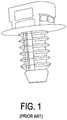
- In the prior art, as shown in
Figure 1 , hole retainers are typically fir tree designs. However, such fir tree designs are intended to be used in panel mount applications which are not typically threaded. When these fir tree designs are used in a threaded hole applications the engage force (i.e. to insert) is significantly higher than if mounted in a panel hole. This is a result of the cumulative deformation of the fir features, the deeper the engagement, the greater the engagement force. This results in the hole retainers being not fully seated as well as ergonomic complaints from operators. - The present application is directed to a hole retainer with features that allow it to be inserted into a threaded hole with lower and constant engage force that provides the same or higher level of retention than prior art fir tree designs. As noted in more detail below staggered locking teeth can match thread size and pitch and provide constant engagement with threads within a hole regardless of retainer installation orientation. Additionally, flexible lock arms are configured to engage on one side only. The lock arm design functions in a manner that flexes easily during installation to reduce insertion effort. Then once engaged, breakage is required for extraction without unscrewing (twisting) from hole, resulting in a high retention to insertion ratio.
- To this end, the present arrangement provides a hole retainer for insertion into a threaded hole. The hole retainer has a saddle configured to accept and retain an object, a stabilizing post, and a plurality of staggered locking teeth. The staggered locking teeth extend from the bottom of the stabilizing post upward in a manner such that they engage with threads inside the threaded hole.
- The present invention can be best understood through the following description and accompanying drawings, wherein:
-
Figure 1 shows a prior art fir tree hold retainer; -
Figure 2A and 2B show a hole retainer, in accordance with one embodiment; and -
Figure 3 shows a hole retainer with a threaded hole, in accordance with one embodiment. - The present arrangement as shown in
Figures 2A and 2B , a threadedhole retainer 10 is shown having awire bundle saddle 12, apre load flange 14, a stabilizingpost 16, four (4)anti-rattle rail posts 18 and two staggered locking teeth 20a (upper) and 20b (lower). -
Retainer 10 is typically constructed from injection molding using Polyamide 66 or Polyamide 46, however, the features of the present arrangement may be used with other polymers depending on the application.Wire bundle saddle 12 is the structure onretainer 10 that is configured to receive the wire harness.Wire saddle 12 aids in the installation of the wire harness covering or other objects attached toretainer 10, providing a more uniform fit for the wire harness as compared to prior art retainer such as the fir tree clips. - Preload
flange 14 is designed to help maintain proper tooth engagement to the threads in the threaded hole once stabilizingpost 16 and staggeredlocking teeth retainer 10 are installed.Anti-rattle posts 18 located near the top of stabilizingpost 16 keep threadedhole retainer 10 from moving laterally within the threaded hole and in instances where "noise" or vibration is a concern. Suchanti rattle posts 18 serve to keepretainer 10 and an attached (wire harness) in a stable attached position. - As shown in
Figures 2A and 2B , staggered locking teeth 20a and 20b extend from a bottom portion of stabilizingpost 16 and extend upward. Teeth 20a and 20b are advantageously angled to match the threads of the hole into whichretainer 10 is to be inserted in order to maximize engagement area. Although the present illustration shows two locking teeth 20a and 20b, it is understood that more or less teeth may be used, and angled differently if needed, depending on the application and in particular the dimensions of the threaded hole thatretainer 10 is intended for. - When in use as shown in
Figure 3 ,hole retainer 10 is inserted into a threadedhole 50 screwing in Stabilizer 16 and teeth 20a and 20b, either clockwise or counterclockwise depending on type of threads in the hole and can be removed screwing out. In a preferred method,retainer 10 is installed by simply pushing threaded hole retainer directly into threaded hole such that teeth 20 simply deflect during insertion. - During the
installation process retainer 10 is inserted to a depth such thatpreload flange 14 flexes so that once teeth 20a and 20b are engaged with the threads in the hole,preload flange 14 provides directed pressure to the threaded hole to help holdretainer 10 in position. As noted above, withretainer 10 inserted,anti-rattle posts 18 work to keep threadedhole retainer 10 stable. - While only certain features of the invention have been illustrated, and described herein, many modifications, substitutions, changes or equivalents will now occur to those skilled in the art. It is therefore, to be understood that this application is intended to cover all such modifications and changes that fall within the true spirit of the invention.
Claims (7)
- A hole retainer for insertion into a threaded hole, said hole retainer comprising:a saddle configured to accept and retain an object;a stabilizing post; anda plurality of staggered locking teeth,wherein said staggered locking teeth extend from the bottom of said stabilizing post upward in a manner such that they engage with threads inside said threaded hole.
- The hole retainer as claimed in claim 1, wherein said saddle is a wire bundle saddle for accepting and retaining a wire bundle.
- The hole retainer as claimed in claim 1, wherein said hole retainer further comprises a pre-load flange at the top of said stabilizing post, said pre-load flange configured, upon insertion of said hole retainer into said threaded hole, to flex and press down against the top of said threaded hole to stabilize said hole retainer in said threaded hole.
- The hole retainer as claimed in claim 1, wherein said hole retainer further comprises anti-rattle rail posts on said stabilizing post, said anti-rattle posts configured to assist in retaining said stabilizing post within said threaded hole and to suppress vibrations.
- The hole retainer as claimed in claim 1, wherein said hole retainer is constructed from either one of injection molded Polyamide 66 or Polyamide 46.
- The hole retainer as claimed in claim 1, wherein said staggered locking teeth are configured to deflect when pushed into the threaded hole and then, once stabilizing post is fully inserted, extend back into the threads of said threaded hole.
- The hole retainer as claimed in claim 1, wherein said staggered locking teeth are configured to engage the threads of said threaded hole for insertion by turning until said stabilizing post is fully inserted into said threaded hole.
Applications Claiming Priority (1)
| Application Number | Priority Date | Filing Date | Title |
|---|---|---|---|
| US14/987,070 US9899822B2 (en) | 2016-01-04 | 2016-01-04 | Threaded hole retainer |
Publications (1)
| Publication Number | Publication Date |
|---|---|
| EP3187738A1 true EP3187738A1 (en) | 2017-07-05 |
Family
ID=57758468
Family Applications (1)
| Application Number | Title | Priority Date | Filing Date |
|---|---|---|---|
| EP16306763.0A Withdrawn EP3187738A1 (en) | 2016-01-04 | 2016-12-21 | Threaded hole retainer |
Country Status (2)
| Country | Link |
|---|---|
| US (1) | US9899822B2 (en) |
| EP (1) | EP3187738A1 (en) |
Cited By (2)
| Publication number | Priority date | Publication date | Assignee | Title |
|---|---|---|---|---|
| TWI624602B (en) * | 2017-08-04 | 2018-05-21 | 吳易璋 | Pressing type screw |
| EP4369573A4 (en) * | 2021-07-05 | 2025-06-25 | Toshiba Industrial Products and Systems Corporation | Cable holding structure for rotating electrical machine |
Families Citing this family (14)
| Publication number | Priority date | Publication date | Assignee | Title |
|---|---|---|---|---|
| CN105690405B (en) * | 2016-04-20 | 2017-11-28 | 机器时代(北京)科技有限公司 | Fastener and attachment cap and assembly component and robot |
| JP2019011841A (en) * | 2017-06-30 | 2019-01-24 | トヨタ自動車株式会社 | Female screw hole block plug |
| US10619659B2 (en) * | 2017-08-03 | 2020-04-14 | U.S. Farathane Corporation | Closure assembly with collapsible crush barbs configured within a recess cavity defining edge of a first piece for engagement by a projection of a second piece when press fit within the recess cavity in order to engage the pieces together |
| US10808657B2 (en) | 2018-02-02 | 2020-10-20 | Ford Global Technologies, Llc | Vehicle component with an accessory mounting feature and a method and tool for forming |
| US10986976B2 (en) | 2018-06-25 | 2021-04-27 | Whirlpool Corporation | Dishwasher with door latch assembly |
| US10823209B2 (en) * | 2018-10-05 | 2020-11-03 | Toyota Motor Engineering & Manufacturing North America, Inc. | Clamp assemblies and grille assemblies with wire harness clamp attachment structures |
| US10808745B1 (en) * | 2019-10-11 | 2020-10-20 | A. Raymond Et Cie | Releasable slot fastener |
| US11142381B1 (en) * | 2020-07-27 | 2021-10-12 | Hellermann Tyton Corporation | Saddle that adjusts to a bundle diameter |
| USD1049838S1 (en) * | 2022-10-18 | 2024-11-05 | Avery Dennison Retail Information Services Llc | Fastener device |
| EP4455492B1 (en) | 2023-04-28 | 2026-07-29 | HellermannTyton Corporation | Cable tie cradle mount fixings |
| US12413062B2 (en) * | 2023-08-23 | 2025-09-09 | Aptiv Technologies AG | Mounting device for securing and routing elongated articles |
| US12680626B2 (en) | 2023-09-11 | 2026-07-14 | Hellermanntyton Corporation | Stretch-mount clamp assemblies |
| US12631206B2 (en) | 2023-10-20 | 2026-05-19 | Hellermanntyton Corporation | Twist-lock fixings |
| WO2025229049A1 (en) * | 2024-05-02 | 2025-11-06 | Zephyros, Inc. | Fixation of an insert to a socket of a nut |
Citations (6)
| Publication number | Priority date | Publication date | Assignee | Title |
|---|---|---|---|---|
| EP1830076A1 (en) * | 2006-03-01 | 2007-09-05 | Renault SAS | Fixing slug and assembly comprising such a slug |
| WO2009042824A1 (en) * | 2007-09-27 | 2009-04-02 | Newfrey Llc | Internal thread hole closing plug |
| EP2369187A1 (en) * | 2010-03-10 | 2011-09-28 | Daiwa Kasei Kogyo Kabushiki Kaisha | Clip |
| US20130119208A1 (en) * | 2004-04-30 | 2013-05-16 | Hellermanntyton Corporation | Fir tree mount for cable ties |
| JP2014167324A (en) * | 2013-02-28 | 2014-09-11 | Kitagawa Kogyo Co Ltd | Fixing mechanism |
| DE102014008690A1 (en) * | 2014-06-12 | 2015-12-17 | GM Global Technology Operations LLC (n. d. Ges. d. Staates Delaware) | Fastening element with multipart thread |
Family Cites Families (10)
| Publication number | Priority date | Publication date | Assignee | Title |
|---|---|---|---|---|
| US5672038A (en) * | 1995-11-20 | 1997-09-30 | Ford Global Technologies, Inc. | Fastener |
| US5907891A (en) * | 1998-02-24 | 1999-06-01 | Illinois Tool Works Inc. | Tree fastener with split wings |
| US5906465A (en) * | 1998-06-23 | 1999-05-25 | Yazaki Corporation | Low insertion force and high retention force Christmas tree-type clip |
| DE19828073C1 (en) * | 1998-06-24 | 2000-03-30 | Itw Ateco Gmbh | Plastic cable holder for vehicles |
| JP2004242478A (en) * | 2003-02-10 | 2004-08-26 | Nippon Pop Rivets & Fasteners Ltd | Cable clamp |
| US8028962B2 (en) * | 2004-04-30 | 2011-10-04 | Hellermanntyton Corporation | Fir tree mount for cable ties |
| US7753320B2 (en) * | 2005-07-28 | 2010-07-13 | Hellermanntyton Corporation | Flush mount connector clip |
| US7866612B2 (en) * | 2006-10-23 | 2011-01-11 | Sumitomo Wiring Systems, Ltd. | Clamp for use in wire harness |
| US7891926B2 (en) * | 2008-01-28 | 2011-02-22 | A. Raymond, Inc. | Fastener |
| US7896601B2 (en) * | 2009-01-22 | 2011-03-01 | Marimba Auto, Llc | Two-piece Fastener |
-
2016
- 2016-01-04 US US14/987,070 patent/US9899822B2/en active Active
- 2016-12-21 EP EP16306763.0A patent/EP3187738A1/en not_active Withdrawn
Patent Citations (6)
| Publication number | Priority date | Publication date | Assignee | Title |
|---|---|---|---|---|
| US20130119208A1 (en) * | 2004-04-30 | 2013-05-16 | Hellermanntyton Corporation | Fir tree mount for cable ties |
| EP1830076A1 (en) * | 2006-03-01 | 2007-09-05 | Renault SAS | Fixing slug and assembly comprising such a slug |
| WO2009042824A1 (en) * | 2007-09-27 | 2009-04-02 | Newfrey Llc | Internal thread hole closing plug |
| EP2369187A1 (en) * | 2010-03-10 | 2011-09-28 | Daiwa Kasei Kogyo Kabushiki Kaisha | Clip |
| JP2014167324A (en) * | 2013-02-28 | 2014-09-11 | Kitagawa Kogyo Co Ltd | Fixing mechanism |
| DE102014008690A1 (en) * | 2014-06-12 | 2015-12-17 | GM Global Technology Operations LLC (n. d. Ges. d. Staates Delaware) | Fastening element with multipart thread |
Cited By (2)
| Publication number | Priority date | Publication date | Assignee | Title |
|---|---|---|---|---|
| TWI624602B (en) * | 2017-08-04 | 2018-05-21 | 吳易璋 | Pressing type screw |
| EP4369573A4 (en) * | 2021-07-05 | 2025-06-25 | Toshiba Industrial Products and Systems Corporation | Cable holding structure for rotating electrical machine |
Also Published As
| Publication number | Publication date |
|---|---|
| US9899822B2 (en) | 2018-02-20 |
| US20170302062A1 (en) | 2017-10-19 |
Similar Documents
| Publication | Publication Date | Title |
|---|---|---|
| US9899822B2 (en) | Threaded hole retainer | |
| US7954205B2 (en) | Clip retainer | |
| EP2381553A2 (en) | Clamp | |
| US7051408B2 (en) | Spring clip for fixing two parts to each other | |
| US9776578B2 (en) | Clip and pillar garnish fixing structure | |
| US9004415B2 (en) | Clamp | |
| US9889778B2 (en) | Armrest structure for door trim | |
| US20130252060A1 (en) | Battery Hold Down Device | |
| US20170159849A1 (en) | Cable Tie Assembly | |
| US9689419B2 (en) | Temporary attachment and a holder for a member to be held | |
| CN111033079A (en) | Grommet | |
| EP3337692A1 (en) | Retainer to secure fastener of door trim panel | |
| KR102892828B1 (en) | Anti-wobble fir tree mount | |
| US9234540B2 (en) | Retainer—spring steel single thread engagement | |
| US9453594B2 (en) | Fixing device | |
| EP3444485B1 (en) | Fastener and fastening arrangement | |
| DE102016115385A1 (en) | RING BRACKET FOR VERIFICATION OF SNAP-LOCK INTERVENTION | |
| KR20180066349A (en) | Fasten for mounting sunroof of vehicle | |
| DE102014224973A1 (en) | Device for holding a system component on a connection part of a vehicle | |
| US20180216643A1 (en) | Support member | |
| CN106605070A (en) | Retainer | |
| JP2010064588A (en) | Securing device of spare tire | |
| KR20170075989A (en) | Protector of dash grommet for vehicle | |
| US20060099049A1 (en) | Fastener/stud retainer | |
| JP2010266053A (en) | clip |
Legal Events
| Date | Code | Title | Description |
|---|---|---|---|
| PUAI | Public reference made under article 153(3) epc to a published international application that has entered the european phase |
Free format text: ORIGINAL CODE: 0009012 |
|
| STAA | Information on the status of an ep patent application or granted ep patent |
Free format text: STATUS: THE APPLICATION HAS BEEN PUBLISHED |
|
| AK | Designated contracting states |
Kind code of ref document: A1 Designated state(s): AL AT BE BG CH CY CZ DE DK EE ES FI FR GB GR HR HU IE IS IT LI LT LU LV MC MK MT NL NO PL PT RO RS SE SI SK SM TR |
|
| AX | Request for extension of the european patent |
Extension state: BA ME |
|
| RAP1 | Party data changed (applicant data changed or rights of an application transferred) |
Owner name: NEXANS |
|
| STAA | Information on the status of an ep patent application or granted ep patent |
Free format text: STATUS: REQUEST FOR EXAMINATION WAS MADE |
|
| 17P | Request for examination filed |
Effective date: 20171228 |
|
| RBV | Designated contracting states (corrected) |
Designated state(s): AL AT BE BG CH CY CZ DE DK EE ES FI FR GB GR HR HU IE IS IT LI LT LU LV MC MK MT NL NO PL PT RO RS SE SI SK SM TR |
|
| STAA | Information on the status of an ep patent application or granted ep patent |
Free format text: STATUS: EXAMINATION IS IN PROGRESS |
|
| 17Q | First examination report despatched |
Effective date: 20190507 |
|
| GRAP | Despatch of communication of intention to grant a patent |
Free format text: ORIGINAL CODE: EPIDOSNIGR1 |
|
| STAA | Information on the status of an ep patent application or granted ep patent |
Free format text: STATUS: GRANT OF PATENT IS INTENDED |
|
| INTG | Intention to grant announced |
Effective date: 20200417 |
|
| STAA | Information on the status of an ep patent application or granted ep patent |
Free format text: STATUS: THE APPLICATION IS DEEMED TO BE WITHDRAWN |
|
| 18D | Application deemed to be withdrawn |
Effective date: 20200828 |