EP3187704A1 - Valve opening and closing timing control apparatus - Google Patents
Valve opening and closing timing control apparatus Download PDFInfo
- Publication number
- EP3187704A1 EP3187704A1 EP16199975.0A EP16199975A EP3187704A1 EP 3187704 A1 EP3187704 A1 EP 3187704A1 EP 16199975 A EP16199975 A EP 16199975A EP 3187704 A1 EP3187704 A1 EP 3187704A1
- Authority
- EP
- European Patent Office
- Prior art keywords
- hole portion
- side rotor
- engaging pin
- camshaft
- valve opening
- Prior art date
- Legal status (The legal status is an assumption and is not a legal conclusion. Google has not performed a legal analysis and makes no representation as to the accuracy of the status listed.)
- Granted
Links
Images



Classifications
-
- F—MECHANICAL ENGINEERING; LIGHTING; HEATING; WEAPONS; BLASTING
- F01—MACHINES OR ENGINES IN GENERAL; ENGINE PLANTS IN GENERAL; STEAM ENGINES
- F01L—CYCLICALLY OPERATING VALVES FOR MACHINES OR ENGINES
- F01L1/00—Valve-gear or valve arrangements, e.g. lift-valve gear
- F01L1/34—Valve-gear or valve arrangements, e.g. lift-valve gear characterised by the provision of means for changing the timing of the valves without changing the duration of opening and without affecting the magnitude of the valve lift
- F01L1/344—Valve-gear or valve arrangements, e.g. lift-valve gear characterised by the provision of means for changing the timing of the valves without changing the duration of opening and without affecting the magnitude of the valve lift changing the angular relationship between crankshaft and camshaft, e.g. using helicoidal gear
- F01L1/3442—Valve-gear or valve arrangements, e.g. lift-valve gear characterised by the provision of means for changing the timing of the valves without changing the duration of opening and without affecting the magnitude of the valve lift changing the angular relationship between crankshaft and camshaft, e.g. using helicoidal gear using hydraulic chambers with variable volume to transmit the rotating force
-
- F—MECHANICAL ENGINEERING; LIGHTING; HEATING; WEAPONS; BLASTING
- F01—MACHINES OR ENGINES IN GENERAL; ENGINE PLANTS IN GENERAL; STEAM ENGINES
- F01L—CYCLICALLY OPERATING VALVES FOR MACHINES OR ENGINES
- F01L1/00—Valve-gear or valve arrangements, e.g. lift-valve gear
- F01L1/02—Valve drive
- F01L1/04—Valve drive by means of cams, camshafts, cam discs, eccentrics or the like
- F01L1/047—Camshafts
-
- F—MECHANICAL ENGINEERING; LIGHTING; HEATING; WEAPONS; BLASTING
- F01—MACHINES OR ENGINES IN GENERAL; ENGINE PLANTS IN GENERAL; STEAM ENGINES
- F01L—CYCLICALLY OPERATING VALVES FOR MACHINES OR ENGINES
- F01L1/00—Valve-gear or valve arrangements, e.g. lift-valve gear
- F01L1/34—Valve-gear or valve arrangements, e.g. lift-valve gear characterised by the provision of means for changing the timing of the valves without changing the duration of opening and without affecting the magnitude of the valve lift
-
- F—MECHANICAL ENGINEERING; LIGHTING; HEATING; WEAPONS; BLASTING
- F02—COMBUSTION ENGINES; HOT-GAS OR COMBUSTION-PRODUCT ENGINE PLANTS
- F02D—CONTROLLING COMBUSTION ENGINES
- F02D13/00—Controlling the engine output power by varying inlet or exhaust valve operating characteristics, e.g. timing
- F02D13/02—Controlling the engine output power by varying inlet or exhaust valve operating characteristics, e.g. timing during engine operation
- F02D13/0203—Variable control of intake and exhaust valves
- F02D13/0215—Variable control of intake and exhaust valves changing the valve timing only
- F02D13/0219—Variable control of intake and exhaust valves changing the valve timing only by shifting the phase, i.e. the opening periods of the valves are constant
-
- F—MECHANICAL ENGINEERING; LIGHTING; HEATING; WEAPONS; BLASTING
- F15—FLUID-PRESSURE ACTUATORS; HYDRAULICS OR PNEUMATICS IN GENERAL
- F15B—SYSTEMS ACTING BY MEANS OF FLUIDS IN GENERAL; FLUID-PRESSURE ACTUATORS, e.g. SERVOMOTORS; DETAILS OF FLUID-PRESSURE SYSTEMS, NOT OTHERWISE PROVIDED FOR
- F15B13/00—Details of servomotor systems ; Valves for servomotor systems
- F15B13/02—Fluid distribution or supply devices characterised by their adaptation to the control of servomotors
- F15B13/04—Fluid distribution or supply devices characterised by their adaptation to the control of servomotors for use with a single servomotor
- F15B13/0401—Valve members; Fluid interconnections therefor
- F15B13/0402—Valve members; Fluid interconnections therefor for linearly sliding valves, e.g. spool valves
-
- F—MECHANICAL ENGINEERING; LIGHTING; HEATING; WEAPONS; BLASTING
- F01—MACHINES OR ENGINES IN GENERAL; ENGINE PLANTS IN GENERAL; STEAM ENGINES
- F01L—CYCLICALLY OPERATING VALVES FOR MACHINES OR ENGINES
- F01L1/00—Valve-gear or valve arrangements, e.g. lift-valve gear
- F01L1/02—Valve drive
- F01L1/04—Valve drive by means of cams, camshafts, cam discs, eccentrics or the like
- F01L1/047—Camshafts
- F01L1/053—Camshafts overhead type
- F01L2001/0537—Double overhead camshafts [DOHC]
-
- F—MECHANICAL ENGINEERING; LIGHTING; HEATING; WEAPONS; BLASTING
- F01—MACHINES OR ENGINES IN GENERAL; ENGINE PLANTS IN GENERAL; STEAM ENGINES
- F01L—CYCLICALLY OPERATING VALVES FOR MACHINES OR ENGINES
- F01L1/00—Valve-gear or valve arrangements, e.g. lift-valve gear
- F01L1/34—Valve-gear or valve arrangements, e.g. lift-valve gear characterised by the provision of means for changing the timing of the valves without changing the duration of opening and without affecting the magnitude of the valve lift
- F01L1/344—Valve-gear or valve arrangements, e.g. lift-valve gear characterised by the provision of means for changing the timing of the valves without changing the duration of opening and without affecting the magnitude of the valve lift changing the angular relationship between crankshaft and camshaft, e.g. using helicoidal gear
- F01L1/3442—Valve-gear or valve arrangements, e.g. lift-valve gear characterised by the provision of means for changing the timing of the valves without changing the duration of opening and without affecting the magnitude of the valve lift changing the angular relationship between crankshaft and camshaft, e.g. using helicoidal gear using hydraulic chambers with variable volume to transmit the rotating force
- F01L2001/34423—Details relating to the hydraulic feeding circuit
-
- F—MECHANICAL ENGINEERING; LIGHTING; HEATING; WEAPONS; BLASTING
- F01—MACHINES OR ENGINES IN GENERAL; ENGINE PLANTS IN GENERAL; STEAM ENGINES
- F01L—CYCLICALLY OPERATING VALVES FOR MACHINES OR ENGINES
- F01L1/00—Valve-gear or valve arrangements, e.g. lift-valve gear
- F01L1/34—Valve-gear or valve arrangements, e.g. lift-valve gear characterised by the provision of means for changing the timing of the valves without changing the duration of opening and without affecting the magnitude of the valve lift
- F01L1/344—Valve-gear or valve arrangements, e.g. lift-valve gear characterised by the provision of means for changing the timing of the valves without changing the duration of opening and without affecting the magnitude of the valve lift changing the angular relationship between crankshaft and camshaft, e.g. using helicoidal gear
- F01L1/3442—Valve-gear or valve arrangements, e.g. lift-valve gear characterised by the provision of means for changing the timing of the valves without changing the duration of opening and without affecting the magnitude of the valve lift changing the angular relationship between crankshaft and camshaft, e.g. using helicoidal gear using hydraulic chambers with variable volume to transmit the rotating force
- F01L2001/34423—Details relating to the hydraulic feeding circuit
- F01L2001/34426—Oil control valves
-
- F—MECHANICAL ENGINEERING; LIGHTING; HEATING; WEAPONS; BLASTING
- F01—MACHINES OR ENGINES IN GENERAL; ENGINE PLANTS IN GENERAL; STEAM ENGINES
- F01L—CYCLICALLY OPERATING VALVES FOR MACHINES OR ENGINES
- F01L1/00—Valve-gear or valve arrangements, e.g. lift-valve gear
- F01L1/34—Valve-gear or valve arrangements, e.g. lift-valve gear characterised by the provision of means for changing the timing of the valves without changing the duration of opening and without affecting the magnitude of the valve lift
- F01L1/344—Valve-gear or valve arrangements, e.g. lift-valve gear characterised by the provision of means for changing the timing of the valves without changing the duration of opening and without affecting the magnitude of the valve lift changing the angular relationship between crankshaft and camshaft, e.g. using helicoidal gear
- F01L1/3442—Valve-gear or valve arrangements, e.g. lift-valve gear characterised by the provision of means for changing the timing of the valves without changing the duration of opening and without affecting the magnitude of the valve lift changing the angular relationship between crankshaft and camshaft, e.g. using helicoidal gear using hydraulic chambers with variable volume to transmit the rotating force
- F01L2001/34423—Details relating to the hydraulic feeding circuit
- F01L2001/34426—Oil control valves
- F01L2001/3443—Solenoid driven oil control valves
-
- F—MECHANICAL ENGINEERING; LIGHTING; HEATING; WEAPONS; BLASTING
- F01—MACHINES OR ENGINES IN GENERAL; ENGINE PLANTS IN GENERAL; STEAM ENGINES
- F01L—CYCLICALLY OPERATING VALVES FOR MACHINES OR ENGINES
- F01L1/00—Valve-gear or valve arrangements, e.g. lift-valve gear
- F01L1/34—Valve-gear or valve arrangements, e.g. lift-valve gear characterised by the provision of means for changing the timing of the valves without changing the duration of opening and without affecting the magnitude of the valve lift
- F01L1/344—Valve-gear or valve arrangements, e.g. lift-valve gear characterised by the provision of means for changing the timing of the valves without changing the duration of opening and without affecting the magnitude of the valve lift changing the angular relationship between crankshaft and camshaft, e.g. using helicoidal gear
- F01L1/3442—Valve-gear or valve arrangements, e.g. lift-valve gear characterised by the provision of means for changing the timing of the valves without changing the duration of opening and without affecting the magnitude of the valve lift changing the angular relationship between crankshaft and camshaft, e.g. using helicoidal gear using hydraulic chambers with variable volume to transmit the rotating force
- F01L2001/34423—Details relating to the hydraulic feeding circuit
- F01L2001/34426—Oil control valves
- F01L2001/34433—Location oil control valves
-
- F—MECHANICAL ENGINEERING; LIGHTING; HEATING; WEAPONS; BLASTING
- F01—MACHINES OR ENGINES IN GENERAL; ENGINE PLANTS IN GENERAL; STEAM ENGINES
- F01L—CYCLICALLY OPERATING VALVES FOR MACHINES OR ENGINES
- F01L1/00—Valve-gear or valve arrangements, e.g. lift-valve gear
- F01L1/34—Valve-gear or valve arrangements, e.g. lift-valve gear characterised by the provision of means for changing the timing of the valves without changing the duration of opening and without affecting the magnitude of the valve lift
- F01L1/344—Valve-gear or valve arrangements, e.g. lift-valve gear characterised by the provision of means for changing the timing of the valves without changing the duration of opening and without affecting the magnitude of the valve lift changing the angular relationship between crankshaft and camshaft, e.g. using helicoidal gear
- F01L1/3442—Valve-gear or valve arrangements, e.g. lift-valve gear characterised by the provision of means for changing the timing of the valves without changing the duration of opening and without affecting the magnitude of the valve lift changing the angular relationship between crankshaft and camshaft, e.g. using helicoidal gear using hydraulic chambers with variable volume to transmit the rotating force
- F01L2001/34423—Details relating to the hydraulic feeding circuit
- F01L2001/34436—Features or method for avoiding malfunction due to foreign matters in oil
- F01L2001/3444—Oil filters
-
- F—MECHANICAL ENGINEERING; LIGHTING; HEATING; WEAPONS; BLASTING
- F01—MACHINES OR ENGINES IN GENERAL; ENGINE PLANTS IN GENERAL; STEAM ENGINES
- F01L—CYCLICALLY OPERATING VALVES FOR MACHINES OR ENGINES
- F01L1/00—Valve-gear or valve arrangements, e.g. lift-valve gear
- F01L1/34—Valve-gear or valve arrangements, e.g. lift-valve gear characterised by the provision of means for changing the timing of the valves without changing the duration of opening and without affecting the magnitude of the valve lift
- F01L1/344—Valve-gear or valve arrangements, e.g. lift-valve gear characterised by the provision of means for changing the timing of the valves without changing the duration of opening and without affecting the magnitude of the valve lift changing the angular relationship between crankshaft and camshaft, e.g. using helicoidal gear
- F01L1/3442—Valve-gear or valve arrangements, e.g. lift-valve gear characterised by the provision of means for changing the timing of the valves without changing the duration of opening and without affecting the magnitude of the valve lift changing the angular relationship between crankshaft and camshaft, e.g. using helicoidal gear using hydraulic chambers with variable volume to transmit the rotating force
- F01L2001/3445—Details relating to the hydraulic means for changing the angular relationship
- F01L2001/34453—Locking means between driving and driven members
-
- F—MECHANICAL ENGINEERING; LIGHTING; HEATING; WEAPONS; BLASTING
- F01—MACHINES OR ENGINES IN GENERAL; ENGINE PLANTS IN GENERAL; STEAM ENGINES
- F01L—CYCLICALLY OPERATING VALVES FOR MACHINES OR ENGINES
- F01L1/00—Valve-gear or valve arrangements, e.g. lift-valve gear
- F01L1/34—Valve-gear or valve arrangements, e.g. lift-valve gear characterised by the provision of means for changing the timing of the valves without changing the duration of opening and without affecting the magnitude of the valve lift
- F01L1/344—Valve-gear or valve arrangements, e.g. lift-valve gear characterised by the provision of means for changing the timing of the valves without changing the duration of opening and without affecting the magnitude of the valve lift changing the angular relationship between crankshaft and camshaft, e.g. using helicoidal gear
- F01L1/3442—Valve-gear or valve arrangements, e.g. lift-valve gear characterised by the provision of means for changing the timing of the valves without changing the duration of opening and without affecting the magnitude of the valve lift changing the angular relationship between crankshaft and camshaft, e.g. using helicoidal gear using hydraulic chambers with variable volume to transmit the rotating force
- F01L2001/3445—Details relating to the hydraulic means for changing the angular relationship
- F01L2001/34453—Locking means between driving and driven members
- F01L2001/34459—Locking in multiple positions
-
- F—MECHANICAL ENGINEERING; LIGHTING; HEATING; WEAPONS; BLASTING
- F01—MACHINES OR ENGINES IN GENERAL; ENGINE PLANTS IN GENERAL; STEAM ENGINES
- F01L—CYCLICALLY OPERATING VALVES FOR MACHINES OR ENGINES
- F01L1/00—Valve-gear or valve arrangements, e.g. lift-valve gear
- F01L1/34—Valve-gear or valve arrangements, e.g. lift-valve gear characterised by the provision of means for changing the timing of the valves without changing the duration of opening and without affecting the magnitude of the valve lift
- F01L1/344—Valve-gear or valve arrangements, e.g. lift-valve gear characterised by the provision of means for changing the timing of the valves without changing the duration of opening and without affecting the magnitude of the valve lift changing the angular relationship between crankshaft and camshaft, e.g. using helicoidal gear
- F01L1/3442—Valve-gear or valve arrangements, e.g. lift-valve gear characterised by the provision of means for changing the timing of the valves without changing the duration of opening and without affecting the magnitude of the valve lift changing the angular relationship between crankshaft and camshaft, e.g. using helicoidal gear using hydraulic chambers with variable volume to transmit the rotating force
- F01L2001/3445—Details relating to the hydraulic means for changing the angular relationship
- F01L2001/34453—Locking means between driving and driven members
- F01L2001/34469—Lock movement parallel to camshaft axis
-
- F—MECHANICAL ENGINEERING; LIGHTING; HEATING; WEAPONS; BLASTING
- F01—MACHINES OR ENGINES IN GENERAL; ENGINE PLANTS IN GENERAL; STEAM ENGINES
- F01L—CYCLICALLY OPERATING VALVES FOR MACHINES OR ENGINES
- F01L1/00—Valve-gear or valve arrangements, e.g. lift-valve gear
- F01L1/34—Valve-gear or valve arrangements, e.g. lift-valve gear characterised by the provision of means for changing the timing of the valves without changing the duration of opening and without affecting the magnitude of the valve lift
- F01L1/344—Valve-gear or valve arrangements, e.g. lift-valve gear characterised by the provision of means for changing the timing of the valves without changing the duration of opening and without affecting the magnitude of the valve lift changing the angular relationship between crankshaft and camshaft, e.g. using helicoidal gear
- F01L1/3442—Valve-gear or valve arrangements, e.g. lift-valve gear characterised by the provision of means for changing the timing of the valves without changing the duration of opening and without affecting the magnitude of the valve lift changing the angular relationship between crankshaft and camshaft, e.g. using helicoidal gear using hydraulic chambers with variable volume to transmit the rotating force
- F01L2001/3445—Details relating to the hydraulic means for changing the angular relationship
- F01L2001/34479—Sealing of phaser devices
-
- F—MECHANICAL ENGINEERING; LIGHTING; HEATING; WEAPONS; BLASTING
- F01—MACHINES OR ENGINES IN GENERAL; ENGINE PLANTS IN GENERAL; STEAM ENGINES
- F01L—CYCLICALLY OPERATING VALVES FOR MACHINES OR ENGINES
- F01L1/00—Valve-gear or valve arrangements, e.g. lift-valve gear
- F01L1/34—Valve-gear or valve arrangements, e.g. lift-valve gear characterised by the provision of means for changing the timing of the valves without changing the duration of opening and without affecting the magnitude of the valve lift
- F01L1/344—Valve-gear or valve arrangements, e.g. lift-valve gear characterised by the provision of means for changing the timing of the valves without changing the duration of opening and without affecting the magnitude of the valve lift changing the angular relationship between crankshaft and camshaft, e.g. using helicoidal gear
- F01L1/3442—Valve-gear or valve arrangements, e.g. lift-valve gear characterised by the provision of means for changing the timing of the valves without changing the duration of opening and without affecting the magnitude of the valve lift changing the angular relationship between crankshaft and camshaft, e.g. using helicoidal gear using hydraulic chambers with variable volume to transmit the rotating force
- F01L2001/3445—Details relating to the hydraulic means for changing the angular relationship
- F01L2001/34483—Phaser return springs
-
- F—MECHANICAL ENGINEERING; LIGHTING; HEATING; WEAPONS; BLASTING
- F01—MACHINES OR ENGINES IN GENERAL; ENGINE PLANTS IN GENERAL; STEAM ENGINES
- F01L—CYCLICALLY OPERATING VALVES FOR MACHINES OR ENGINES
- F01L13/00—Modifications of valve-gear to facilitate reversing, braking, starting, changing compression ratio, or other specific operations
- F01L2013/11—Sensors for variable valve timing
- F01L2013/111—Camshafts position or phase
-
- F—MECHANICAL ENGINEERING; LIGHTING; HEATING; WEAPONS; BLASTING
- F01—MACHINES OR ENGINES IN GENERAL; ENGINE PLANTS IN GENERAL; STEAM ENGINES
- F01L—CYCLICALLY OPERATING VALVES FOR MACHINES OR ENGINES
- F01L2201/00—Electronic control systems; Apparatus or methods therefor
-
- F—MECHANICAL ENGINEERING; LIGHTING; HEATING; WEAPONS; BLASTING
- F01—MACHINES OR ENGINES IN GENERAL; ENGINE PLANTS IN GENERAL; STEAM ENGINES
- F01L—CYCLICALLY OPERATING VALVES FOR MACHINES OR ENGINES
- F01L2250/00—Camshaft drives characterised by their transmission means
- F01L2250/02—Camshaft drives characterised by their transmission means the camshaft being driven by chains
Definitions
- This disclosure relates to a valve opening and closing timing control apparatus to be provided with a driving side rotor that synchronously rotates with a crankshaft of an internal combustion engine and a driven side rotor that synchronously rotates with a camshaft of the internal combustion engine.
- An apparatus with a configuration enclosing a driven side rotor relatively rotatable with respect to a driving side rotor as a valve opening and closing timing control apparatus connects and fixes the driven side rotor to a camshaft by a connecting bolt, and thus the camshaft and the driven side rotor are maintained at a determined relative phase relationship and the driving side rotor is relatively rotatably supported to the camshaft.
- JP 2002-295208A (Reference 1) as a specific example of the valve opening and closing timing control apparatus with such a configuration, a technology is disclosed in which a pin press-fitted into an end surface of a camshaft is inserted in a positioning hole of a driven side rotor in order to determine the relative phase relationship between the camshaft and the driven side rotor (vane rotor).
- JP 2006-183590A (Reference 2)
- a technology in which a camshaft and a driven side rotor (vane rotor) are connected via a press-fitted member and a positioning pin is fitted between the press-fitted member and the driven side rotor is disclosed.
- JP 2012-172558A (Reference 3) has a configuration in which a connecting member is sandwiched between a camshaft and a driven side rotor (internal rotor).
- Reference 3 a technology is disclosed in which a pin that passes through a pin inserting hole of the connecting member is provided, one end of the pin is inserted in the pin inserting hole of the driven side rotor, and the other end of the pin is inserted in the pin inserting hole of the camshaft.
- a relative rotational phase can be appropriately set in a case of connecting the driven side rotor to the camshaft by the connecting bolt.
- an advance angle flow passage communicating with an advance angle chamber and a retard angle flow passage communicating with a retard angle chamber are formed in the driven side rotor, and thus in a case where the pin is press-fitted into the driven side rotor, it is considered that a sectional area of the flow passage is reduced due to the deformation and deterioration of a response performance is caused.
- dropping of the pin is prevented by press-fitting the pin into one member and the pin is stably held, and thus transition to a process when the pin is inserted in a hole portion formed in the other member is easily performed.
- a valve opening and closing timing control apparatus includes a driving side rotor that synchronously rotates with a crankshaft of an internal combustion engine, a driven side rotor that is disposed coaxially with a rotary axis of the driving side rotor and synchronously rotates with a camshaft for valve opening and closing, a connecting bolt that is disposed coaxially with the rotary axis, and connects the driven side rotor to the camshaft, and a position determination unit that performs positioning between the driven side rotor and the camshaft, or in a case where an intermediate member is provided between the driven side rotor and the camshaft, between the driven side rotor and the intermediate member, or between the camshaft and the intermediate member.
- the position determination unit includes an engaging pin that is in a posture parallel to the rotary axis, a first hole portion into which one end of the engaging pin is fitted is provided in any one of two members performing the positioning, a second hole portion in which the other end of the engaging pin is inserted is provided in the other one, and a deformation absorbing unit that suppresses deformation at a time when the engaging pin is fitted is provided in the vicinity of the first hole portion.
- the deformation absorbing unit suppresses the deformation of the member in which the first hole portion is formed.
- valve opening and closing timing control apparatus in which when connecting the members to each other in the positioning state, the inconvenience caused by the press-fitting of the engaging pin is eliminated is configured.
- the deformation absorbing unit may be configured with a groove that is formed in a posture parallel to the rotary axis at a position adjacent to an outer periphery of the first hole portion.
- the deformation absorbing unit may be configured with a space extending outward from an outer periphery of the first hole portion.
- the space extending outward from the outer periphery of the first hole portion includes a space formed in a slit shape so as to cut and open the outer periphery of the first hole portion, and a space formed in a groove shape extending outward only by setting value in the radial direction from the outer periphery of the first hole portion.
- a flow passage that supplies and discharges a hydraulic oil to an advance angle chamber or a retard angle chamber formed between the driving side rotor and the driven side rotor is formed in the driving side rotor or the intermediate member, and a sectional shape of the flow passage along the rotary axis direction may be different from a sectional shape of the engaging pin.
- a valve opening and closing timing control apparatus A is configured to include an external rotor 20 as a driving side rotor, an internal rotor 30 as a driven side rotor, and a solenoid control valve 40 controlling a hydraulic oil as a working fluid.
- the internal rotor 30 (one example of the driven side rotor) is disposed coaxially with a rotary axis X of an intake camshaft 5, and is screwed and connected to the intake camshaft 5 by a connecting bolt 50 so as to rotate integrally.
- the external rotor 20 (one example of the driving side rotor) is disposed coaxially with the rotary axis X, and is relatively rotatably supported to the internal rotor 30 by containing the internal rotor 30.
- the external rotor 20 synchronously rotates with a crankshaft 1 of an engine E as an internal combustion engine.
- the solenoid control valve 40 is provided with an electromagnetic solenoid 44 supported by the engine E, and is provided with a spool 41 and a spool spring 42 accommodated in a spool chamber 51 S of the connecting bolt 50.
- the electromagnetic solenoid 44 is provided with a plunger 44a disposed at the coaxial core with the rotary axis X so as to abut on an outer end portion of the spool 41, and sets the amount of projection of the plunger 44a to set an operation position of the spool 41 by control of electric power to be supplied to the inside of a solenoid.
- a relative rotational phase of the external rotor 20 and the internal rotor 30 is set by controlling the hydraulic oil (one example of the working fluid). Therefore, control of an opening and closing timing of an intake valve 5V is realized.
- the engine E (one example of the internal combustion engine) of Fig. 1 indicates an engine that is provided in a vehicle such as a passenger car.
- the engine E accommodates a piston 3 in the inside of a cylinder bore in a cylinder block 2 of the upper position, and is configured with four-cycle type to connect the piston 3 and the crankshaft 1 with a connecting rod 4.
- the intake camshaft 5 opening and closing the intake valve 5V and an exhaust camshaft (not illustrated) are provided in upper side of the engine E.
- a supply flow passage 8 is formed to supply the hydraulic oil from a hydraulic pump P (one example of the fluid pressure pump) driven by the engine E.
- the hydraulic pump P supplies lubricating oil stored in the oil pan of the engine E to the solenoid control valve 40 as the hydraulic oil (one example of the working fluid) via the supply flow passage 8.
- a timing chain 7 is wound over an output sprocket 6 formed in the crankshaft 1 of the engine E and the timing sprocket 22S of the external rotor 20. Thereby, the external rotor 20 synchronously rotates with the crankshaft 1.
- a sprocket is provided to the front end of the exhaust camshaft of exhaust side, and the timing chain 7 is wound in the sprocket.
- the external rotor 20 rotates toward a driving rotational direction S by the driving force from the crankshaft 1.
- the direction in which the internal rotor 30 is relatively rotated in the same direction as the driving rotational direction S with respect to the external rotor 20 is referred to as an advance angle direction Sa, and the reverse direction thereof is referred to as a retard angle direction Sb.
- relationship between the crankshaft 1 and the intake camshaft 5 is set so as to increase an intake air compression ratio in accordance with increase of the amount of displacement when the relative rotational phase is displaced in the advance angle direction Sa, and so as to reduce the intake air compression ratio in accordance with the increase of the amount of displacement when the relative rotational phase is displaced in the retard angle direction Sb.
- valve opening and closing timing control apparatus A is provided in the intake camshaft 5 in the embodiment, the valve opening and closing timing control apparatus A may be provided in the exhaust camshaft, or may be provided in both of the intake camshaft 5 and the exhaust camshaft.
- the external rotor 20 includes the external rotor main body 21, a front plate 22, and a rear plate 23, and these portions are integrated by engagement of a plurality of fastening bolts 24.
- the timing sprocket 22S is formed on an outer periphery of the front plate 22.
- An intermediate member 9 is disposed on an inner periphery of the front plate 22, and a bolt head 52 of the connecting bolt 50 is crimped with respect to the intermediate member 9. Therefore, the intermediate member 9, the internal rotor main body 31, and the intake valve 5V are integrated.
- a plurality of projecting portions 21 T projecting towards the inside in a radial direction is integrally formed in the external rotor main body 21.
- the internal rotor 30 includes the cylindrical internal rotor main body 31 which is brought into close contact with the projecting portion 21T of the external rotor main body 21, and four vane portions 32 which project towards the outside in the radial direction from the outer periphery of the internal rotor main body 31 so as to come into contact with an inner peripheral surface of the external rotor main body 21.
- the external rotor 20 contains the internal rotor 30, and the plurality of the fluid pressure chambers C are formed on the outer periphery side of the internal rotor main body 31 at an intermediate position of the projecting portion 21T adjacent to each other in the rotation direction.
- These fluid pressure chambers C are partitioned by the vane portion 32, and an advance angle chamber Ca and a retard angle chamber Cb are partitioned and formed.
- a plurality of advance angle flow passages 33 (four) communicating with the advance angle chamber Ca are formed in the internal rotor 30, and a plurality of retard angle flow passages 34 (four) communicating with the retard angle chamber Cb are formed in the internal rotor 30.
- a torsion spring 28 assisting a displacement of the relative rotational phase between the external rotor 20 and the internal rotor 30 (hereinafter, referred to as the relative rotational phase) to the advance angle direction Sa by the action of biasing force from most retarded angle phase to the advance angle direction Sa is provided over the external rotor 20 and the intermediate member 9.
- a locking mechanism L locking (fixing) the relative rotational phase between the external rotor 20 and the internal rotor 30 in the most retarded angle phase is provided.
- the locking mechanism L is configured to be provided with a locking member 26 supported freely movable in the direction along the rotary axis X with respect to the one vane portion 32, a locking spring (not illustrated) projected and biased the locking member 26, and a locking recess portion (not illustrated) formed on the rear plate 23.
- the locking mechanism L may be configured to be provided with the locking member 26 guided so as to be moved along a radial direction.
- the relative rotational phase reaches the most retarded angle phase. Therefore, the locking member 26 is engaged with the locking recess portion by the biasing force of the locking spring, and the locking mechanism L serves to maintain the relative rotational phase to the most retarded angle phase.
- the locking mechanism L is also configured to perform lock releasing to detach the locking member 26 from the locking recess portion by a hydraulic oil pressure.
- the connecting bolt 50 is provided with a bolt body 51 of which a portion is cylindrical, a cylindrical sleeve 55 fitted in a cylindrical portion of the bolt body 51, and a regulation pin 57 as an engagement member positioning these portions.
- a female threaded portion 5S is formed around the rotary axis X, and an inside space of the shaft 5T as a larger diameter than the female threaded portion 5S is formed so that the sleeve 55 is tightly fitted.
- the inside space of the shaft 5T communicates with the supply flow passage 8 as described above.
- the hydraulic oil is supplied from the hydraulic pump P to the inside space of the shaft 5T.
- the bolt head 52 is formed on the outer end portion of the bolt body 51 and a male threaded portion 53 is formed on an inner end portion. Based on the configuration, the male threaded portion 53 of the bolt body 51 is screwed to the female threaded portion 5S of the intake camshaft 5, and the internal rotor 30 is fastened to the intake camshaft 5 by rotational operation of the bolt head 52.
- an inner end side of the outer periphery (male screw side) of the sleeve 55 being fitted in the bolt body 51 is in close contact with the inner peripheral surface of the inside space of the shaft 5T, and the outer peripheral surface of an outer end side (bolt head side) of the sleeve 55 is in close contact with the inner peripheral surface of the internal rotor main body 31.
- the hole-shaped inner space is formed towards in the direction of the male threaded portion 53 from the bolt head 52, a retainer 54 is press-fitted and fixed to the inner space. Therefore, the inner space is divided by the retainer 54, and the spool chamber 51 S and a hydraulic oil chamber 51 T as a fluid chamber are formed in a non-communicated state.
- the spool chamber 51 S is formed in a cylinder inner surface shape and the spool 41 is reciprocally movably accommodated along the rotary axis X in the spool chamber 51 S. Therefore, the spool spring 42 is disposed between the inside end of the spool 41 and the retainer 54. Thereby, the spool 41 is biased so as to project in the direction of the outer end side (direction of the bolt head 52).
- the plurality of acquisition flow passages 51m communicating the hydraulic oil chamber 51 T and the inside space of the shaft 5T are formed and the plurality of intermediate flow passages 51n are formed between the hydraulic oil chamber 51 T and the outer peripheral surface of the bolt body 51.
- a check valve CV is provided in the flow passage sending the hydraulic oil from the acquisition flow passage 51 m to the intermediate flow passage 51 n in the hydraulic oil chamber 51 T.
- This check valve CV is configured with a ball holder 61, a check spring 62, and a check ball 63.
- the check spring 62 is disposed between the retainer 54 and the check ball 63 and the check ball 63 is in pressure contact with an opening of the ball holder 61 by the biasing force of the check spring 62 to close the flow passage.
- An oil filter 64 removing dust from the hydraulic oil flowing toward the check ball 63 is provided in the ball holder 61.
- the check valve CV opens the flow passage against the biasing force of the check spring 62 and in a case where the pressure is decreased less than the predetermined value, the check valve CV closes the flow passage by the biasing force of the check spring 62.
- the solenoid control valve 40 is provided with the spool 41, the spool spring 42, and the electromagnetic solenoid 44.
- a plurality of pump ports 50P communicating the spool chamber 51 S and the outer peripheral surface of the bolt body 51 are formed as a through hole in the bolt body 51.
- the plurality of advance angle ports 50A and a plurality of retard angle ports 50B communicating the spool chamber 51 S and the outer peripheral surface of the sleeve 55 are formed as the through hole over the bolt body 51 and the sleeve 55 in the connecting bolt 50.
- the advance angle port 50A, the pump port 50P, and the retard angle port 50B are disposed in the inner end side from the outer end side of the connecting bolt 50 in this order.
- the advance angle port 50A and the retard angle port 50B in the direction as viewed along the rotary axis X are formed in the overlapping positions with each other and the pump port 50P is formed in a position that does not overlap with these ports.
- annular groove is formed in which the plurality of the advance angle ports 50A communicate and the plurality of the advance angle ports 50A communicate with the plurality of the advance angle flow passages 33 from the annular groove.
- annular groove is formed in which the plurality of the retard angle ports 50B communicate and the plurality of the retard angle ports 50B communicate with the plurality of the retard angle flow passages 34 from the annular groove.
- a plurality of introduction flow passages 56 communicating the intermediate flow passage 51n and the pump port 50P are formed in a groove shape on the inner peripheral surface of the sleeve 55.
- the sleeve 55 is shaped at a dimension reaching a position covering the intermediate flow passage 51 n from the bolt head 52 of the bolt body 51 and the introduction flow passage 56 is formed in a region avoiding the advance angle port 50A and the retard angle port 50B.
- a first engaging portion 51f as a hole with a bag shape is formed at a position deviated from a press-fitted and fixed position of the retainer 54 in the direction along the rotary axis X in the bolt body 51, a second engaging portion 55f having a hole shape penetrating in the radial direction is formed, and the regulation pin 57 to engage with both portions is provided in the sleeve 55.
- the regulation pin 57 is press-fitted and fixed to the first engaging portion 51 f.
- the second engaging portion 55f is formed in a long hole shape of which the direction along the rotary axis X is larger than the direction perpendicular thereto.
- a slight gap to allow relative movement in the direction along the rotary axis X of the bolt body 51 and the sleeve 55 is formed between the second engaging portion 55f and the regulation pin 57 from the configuration.
- the sleeve 55 is configured to be movable respectively only by an amount corresponding to the gap between the second engaging portion 55f and the regulation pin 57 in the direction along the rotary axis X with respect to the bolt body 51, while maintaining a relative posture of the rotation around the rotary axis X of the bolt body 51 and the sleeve 55.
- the relative posture of the rotation around the rotary axis X of the bolt body 51 and the sleeve 55 and a relative position thereof along the rotary axis X are determined. Accordingly, the hydraulic oil from the hydraulic oil chamber 51T may be supplied to the pump port 50P via the acquisition flow passage 51 m, the check valve CV, the intermediate flow passage 51 n, and the introduction flow passage 56.
- the spool 41 forms an abutting surface on which the plunger 44a abuts on the outer end side, forms land portions 41 A at two positions in the direction along the rotary axis X, and forms a groove portion 41 B at an intermediate position of these land portions 41 A.
- the spool 41 is formed in a hollow and a drain hole 41 D is formed on a projecting end of the spool 41.
- the spool 41 abuts on a stopper 43 provided on an inner peripheral opening of the outer end side of the connecting bolt 50, so that a position of a projecting side is determined.
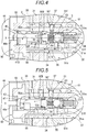
- the solenoid control valve 40 causes the plunger 44a to abut on the abutting surface of the spool 41 and controls the amount of projection. Therefore, as illustrated in Fig. 3 , Fig. 4, and Fig.5 , the solenoid control valve 40 is configured to be capable of setting the spool 41 at a neutral position, a retard angle position, and an advance angle position.
- the spool 41 is set at the neutral position illustrated in Fig. 3 , so that the advance angle port 50A and the retard angle port 50B are closed at the same time by a pair of the land portions 41A of the spool 41.
- the feeding and discharging of the hydraulic oil to the advance angle chamber Ca and the retard angle chamber Cb is not preformed and the phase of the valve opening and closing timing control apparatus A is maintained.
- the plunger 44a is retracted (operated outwards) on the basis of the neutral position by the control of the electromagnetic solenoid 44, so that the spool 41 is set at the advance angle position illustrated in Fig. 4 .
- the pump port 50P communicates with the advance angle port 50A via the groove portion 41 B at the advance angle position.
- the retard angle port 50B communicates with the spool chamber 51 S from the inner end of the spool 41.
- the hydraulic oil is supplied to the advance angle chamber Ca, the hydraulic oil flows to the inside of the spool 41 from the retard angle chamber Cb, and the hydraulic oil is discharged from the drain hole 41 D (flow of the hydraulic oil is illustrated by an arrow in Fig. 4 ).
- a rotation phase of the intake camshaft 5 is displaced in the advance angle direction Sa.
- the retard angle position coincides with the position in which the spool 41 abuts on the stopper 43 by the biasing force of the spool spring 42.
- the spool 41 In a state where the locking mechanism L is in a lock state, the spool 41 is set at the advance angle position and in a case where the hydraulic oil is supplied to the advance angle flow passage 33, the hydraulic oil is supplied to the locking recess portion of the locking mechanism L from the advance angle flow passage 33. Therefore, the locking member 26 is detached from the locking recess portion and the lock state of the locking mechanism L is released.
- the plunger 44a is projected (operated inwards) on the basis of the neutral position by the control of the electromagnetic solenoid 44, so that the spool 41 is set at the retard angle position illustrated in Fig. 5 .
- the pump port 50P communicates with the retard angle port 50B via the groove portion 41 B at the retard angle position.
- the advance angle port 50A communicates with a drain space (space continued to the outer end side from the spool chamber 51 S).
- the hydraulic oil is supplied to the retard angle chamber Cb and at the same time the hydraulic oil is discharged from the advance angle chamber Ca (flow of the hydraulic oil is illustrated by an arrow in Fig. 5 ).
- the rotation phase of the intake camshaft 5 is displaced in the retard angle direction Sb.
- the valve opening and closing timing control apparatus A is provided with a front position determination unit FB that determines a positional relationship around the rotary axis X of the internal rotor 30 and the intermediate member 9, and a rear position determination unit RB that determines the positional relationship around the rotary axis X of the internal rotor 30 and the intake camshaft 5.
- the front position determination unit FB is provided with a front engaging pin 71 in a posture parallel to the rotary axis X
- the rear position determination unit RB is provided with a rear engaging pin 72 in a posture parallel with the rotary axis X.
- An aluminum alloy is used in the internal rotor main body 31, and a steel material is used in the intermediate member 9 and the intake camshaft.
- a cylindrical portion 9A and a connecting wall portion 9B are integrally formed in the intermediate member 9, and a circular opening portion 9C is formed around the rotary axis X in the connecting wall portion 9B.
- a connecting contact surface 9s is formed on a surface facing the internal rotor main body 31 of the connecting wall portion 9B.
- An abutting contact surface 5p is formed on the surface facing the internal rotor main body 31 of the intake camshaft 5.
- a front contact surface 31f is formed in a recessed shape in which the connecting wall portion 9B is fitted, on a side where the intermediate member 9 is disposed of the internal rotor main body 31, and the connecting contact surface 9s of the connecting wall portion 9B is disposed in a contact state to the front contact surface 31f.
- a rear contact surface 31 r is formed in a recessed shape in which the intake camshaft 5 is fitted, on a side where the intake camshaft 5 is disposed of the internal rotor main body 31, and the abutting contact surface 5p of the intake camshaft 5 is disposed in a contact state to the rear contact surface 31 r.
- the advance angle flow passage 33 is configured with a first advance angle flow passage 33a that is formed along a boundary part between the front contact surface 31f of the internal rotor main body 31 and the connecting contact surface 9s of the intermediate member 9 in the radial direction, a second advance angle flow passage 33b that is formed in the internal rotor main body 31 in a posture parallel to the rotary axis X from the outer end position of the first advance angle flow passage 33a, and a third advance angle flow passage 33c that is formed in the internal rotor main body 31 from the second advance angle flow passage 33b in the radial direction.
- first advance angle flow passages 33a is formed in a groove shape along the radial direction on the connecting contact surface 9s.
- a portion of four first advance angle flow passages 33a is formed in a groove shape along the radial direction on the front contact surface 31f of the internal rotor main body 31.
- the second advance angle flow passage 33b and the third advance angle flow passage 33c communicating with the first advance angle flow passage 33a are formed in the inside of the internal rotor main body 31.
- Position determination unit front position determination unit
- the front position determination unit FB is provided with the front engaging pin 71, the front first hole portion FH1, the front second hole portion FH2, and the deformation absorbing unit R.
- the deformation absorbing unit R may be formed as the space with a non-slit shape extending outward of the front first hole portion FH1 (space with the groove shape continuing to the outer periphery of the front first hole portion FH1) from the outer periphery of the front first hole portion FH1.
- An inner diameter of the front first hole portion FH1 is set to a value slightly smaller than an outer diameter of the front engaging pin 71, the outer peripheral surface of the front engaging pin 71 is in close contact with the inner peripheral surface of the front first hole portion FH1 (becomes a tight-fitted state) by the press-fitting, and a state that the front engaging pin 71 is fixed to the intermediate member 9 is maintained.
- the front engaging pin 71 is fitted in the front first hole portion FH1
- the intermediate member 9 in the vicinity of the front first hole portion FH1 is deformed, and thus a portion of the opening portion 9C is inflated toward the rotary axis X in some cases.
- the deformation absorbing unit R is formed to be the slit shape in order to suppress an inconvenience, in a case of being press-fitted in order to fit the front engaging pin 71, internal stress of the intermediate member 9 is applied in a direction to expand a width of the slit of the deformation absorbing unit R, and thus the deformation inflating the inner periphery of the opening portion 9C is suppressed. Thereby, the fitting accuracy of the sleeve 55 which is disposed in close contact with the inner periphery of the opening portion 9C is maintained in good state.
- the inner diameter of the front second hole portion FH2 is set to a value slightly larger than the outer diameter of the front engaging pin 71, and is configured so that the slight gap is formed between the inner surface of the front second hole portion FH2 and the outer surface of the front engaging pin 71 in an inserted state.
- the front engaging pin 71 is a pin of which a sectional shape is formed in a circular shape, and is formed in noncircular shape tapering the shape of an end position 33t of the first advance angle flow passage 33a (reducing the width by the outer periphery side of the intermediate member 9) formed on the connecting contact surface 9s in order to suppress an erroneous insertion of the front engaging pin 71.
- Such a shape of the end position 33t is different from the sectional shape of the front engaging pin 71 (sectional shape viewed in the direction along the rotary axis X). Therefore, it is not possible to insert the front engaging pin 71 in the portion of the end position 33t, and thus the inconvenience of mistaking the insertion position of the front engaging pin 71 is eliminated.
- Position determination unit rear position determination unit
- a rear first hole portion RH1 into which one end of the rear engaging pin 72 is press-fitted (fitted) is formed on the abutting contact surface 5p in contact with the internal rotor main body 31 of the intake camshaft 5, and the deformation absorbing unit R is formed in the groove of the posture along the rotary axis X on the outer peripheral surface of the intake camshaft 5 that becomes a vicinity position of the rear first hole portion RH1.
- a rear second hole portion RH2 that is inserted in the other end of the rear engaging pin 72 is formed on the rear contact surface 31r in contact with the abutting contact surface 5p of the internal rotor main body 31.
- the rear position determination unit RB is configured with the rear engaging pin 72, the rear first hole portion RH1, the rear second hole portion RH2, and the deformation absorbing unit R.
- An inner diameter of the rear first hole portion RH1 is set to a value slightly smaller than an outer diameter of the rear engaging pin 72, the outer peripheral surface of the rear engaging pin 72 is in close contact with the inner peripheral surface of the rear first hole portion RH1 (becomes the tight-fitted state) by the press-fitting, and a state that the rear engaging pin 72 is fixed to the intake camshaft 5 is maintained.
- the intake camshaft 5 in the vicinity of the rear first hole portion RH1 is deformed, and thus a portion of the outer periphery is inflated outward (direction away from the rotary axis X) in some cases.
- the deformation absorbing unit R in the groove shape is formed to the outer periphery of the intake camshaft 5 in order to eliminate the inconvenience, in a case where the rear engaging pin 72 is press-fitted, internal stress of the intake camshaft 5 is applied in a direction to expand a width of the groove of the deformation absorbing unit R, and thus the deformation inflating the inner periphery is suppressed. Thereby, although a portion of the internal rotor main body 31 is externally fitted to the outer periphery of the intake camshaft 5, a good fitted state is maintained.
- the inner diameter of the rear second hole portion RH2 is set to a value slightly larger than the outer diameter of the rear engaging pin 72, and is configured so that the slight gap is formed between the inner surface of the rear second hole portion RH2 and the outer surface of the front engaging pin 71 in an inserted state.
- the front engaging pin 71 is press-fitted and fixed (fitted) to the front first hole portion FH1 of the intermediate member 9, and the rear engaging pin 72 is press-fitted and fixed (fitted) to the rear first hole portion RH1 of the intake camshaft 5.
- the front engaging pin 71 and the rear engaging pin 72 can be stably held.
- the front engaging pin 71 is inserted in the front second hole portion FH2 of the internal rotor main body 31, and thus a relative position around the rotary axis X between the internal rotor main body 31 and the intermediate member 9 is determined.
- the sleeve 55 is disposed to be fitted in the opening portion 9C of the intermediate member 9, as described above, even if the front engaging pin 71 is press-fitted, a phenomenon of deforming so as to inflate the inner periphery of the opening portion 9C is suppressed, and thus the sleeve 55 can be surely inserted. Furthermore, a flow passage that supplies and discharges the hydraulic oil is not narrowed by the deformation.
- the rear engaging pin 72 is inserted in the rear second hole portion RH2 of the internal rotor main body 31, and thus a relative position around the rotary axis X between the intake camshaft 5 and the internal rotor main body 31 is determined.
- a portion of the internal rotor main body 31 is externally fitted to the outer periphery of the intake camshaft 5, a phenomenon of deforming so as to inflate the outer periphery of the intake camshaft 5 is eliminated, and thus a work for an external fitting is smoothly performed and an accuracy of the fitting portion is highly maintained.
- the connecting bolt 50 is inserted in the intermediate member 9 and the internal rotor main body 31, the male threaded portion 53 of the connecting bolt 50 is screwed to the female threaded portion 5S of the intake camshaft 5, and the connecting bolt 50 is fastened by the rotation operation. Therefore, the assembly is completed. In the assembly, work of the process such as the sleeve 55 being externally fitted to the connecting bolt 50 and the spool 41 being set to the spool chamber 51 S is performed in advance.
- This disclosure may be used for the valve opening and closing timing control apparatus positioning a plurality of members disposed along the rotary axis by the engaging pin.
Landscapes
- Engineering & Computer Science (AREA)
- Mechanical Engineering (AREA)
- General Engineering & Computer Science (AREA)
- Physics & Mathematics (AREA)
- Fluid Mechanics (AREA)
- Chemical & Material Sciences (AREA)
- Combustion & Propulsion (AREA)
- Valve Device For Special Equipments (AREA)
Description
- This disclosure relates to a valve opening and closing timing control apparatus to be provided with a driving side rotor that synchronously rotates with a crankshaft of an internal combustion engine and a driven side rotor that synchronously rotates with a camshaft of the internal combustion engine.
- An apparatus with a configuration enclosing a driven side rotor relatively rotatable with respect to a driving side rotor as a valve opening and closing timing control apparatus, connects and fixes the driven side rotor to a camshaft by a connecting bolt, and thus the camshaft and the driven side rotor are maintained at a determined relative phase relationship and the driving side rotor is relatively rotatably supported to the camshaft.
- In
JP 2002-295208A - In
JP 2006-183590A - Furthermore,
JP 2012-172558A Reference 3, a technology is disclosed in which a pin that passes through a pin inserting hole of the connecting member is provided, one end of the pin is inserted in the pin inserting hole of the driven side rotor, and the other end of the pin is inserted in the pin inserting hole of the camshaft. - In the apparatus that is provided with the pin which is fitted in the driven side rotor and the camshaft as illustrated in
Reference 1, a relative rotational phase can be appropriately set in a case of connecting the driven side rotor to the camshaft by the connecting bolt. - However, in the apparatus in which the pin is press-fitted into the camshaft as illustrated in
Reference 1, the vicinity of a portion of the camshaft where the pin is inserted is deformed in some cases by the press fitting. In a case where deformation is caused in this manner, a portion of a threaded hole portion of the camshaft is reduced in diameter due to the deformation, and thus an insertion of the connecting bolt becomes difficult, or an engagement with a male screw is not smoothly performed. Therefore, there is room for improvement. - In the configuration in which an intermediate member in contact with an end surface of the driven side rotor is provided and the pin is fitted between the intermediate member and the driven side rotor as illustrated in
Reference 2 orReference 3, it is considered that in a case of adopting the configuration in which the pin is press-fitted into one of hole portions of the driven side rotor and the intermediate member, deformation is caused in the same way as described above and the insertion of the connecting bolt is difficult. - Specifically, an advance angle flow passage communicating with an advance angle chamber and a retard angle flow passage communicating with a retard angle chamber are formed in the driven side rotor, and thus in a case where the pin is press-fitted into the driven side rotor, it is considered that a sectional area of the flow passage is reduced due to the deformation and deterioration of a response performance is caused.
- Although it is considered to increase accuracy between an outer diameter of the pin and an inner diameter of a hole portion into which the pin is press-fitted to eliminate such inconvenience, in a case of performing processing with high precision, an increase in cost is caused, and thus there is room for improvement.
- In a configuration in which positioning is performed using a pin, dropping of the pin is prevented by press-fitting the pin into one member and the pin is stably held, and thus transition to a process when the pin is inserted in a hole portion formed in the other member is easily performed.
- For this reason, when connecting members configuring a valve opening and closing timing control apparatus to each other in a positioning state, it is required to eliminate the inconvenience caused by press-fitting of an engaging pin. Specifically, in a case where a member such as a rotor into which the engaging pin is press-fitted is low strength material such as aluminum, deformation is large at the time of the press-fitting, and thus the deformation becomes a problem.
- A valve opening and closing timing control apparatus according to an aspect of this disclosure includes a driving side rotor that synchronously rotates with a crankshaft of an internal combustion engine, a driven side rotor that is disposed coaxially with a rotary axis of the driving side rotor and synchronously rotates with a camshaft for valve opening and closing, a connecting bolt that is disposed coaxially with the rotary axis, and connects the driven side rotor to the camshaft, and a position determination unit that performs positioning between the driven side rotor and the camshaft, or in a case where an intermediate member is provided between the driven side rotor and the camshaft, between the driven side rotor and the intermediate member, or between the camshaft and the intermediate member. The position determination unit includes an engaging pin that is in a posture parallel to the rotary axis, a first hole portion into which one end of the engaging pin is fitted is provided in any one of two members performing the positioning, a second hole portion in which the other end of the engaging pin is inserted is provided in the other one, and a deformation absorbing unit that suppresses deformation at a time when the engaging pin is fitted is provided in the vicinity of the first hole portion.
- According to this configuration, by fitting the one end side of the engaging pin in the first hole portion, it is possible to support stably the engaging pin. By inserting the other end side of the engaging pin in the second hole portion, a positional relationship between a member in which the first hole portion is formed and a member in which the second hole portion is formed is determined. In a case where the engaging pin is fitted in the first hole portion, even if the member in which the first hole portion is formed is low strength material such as aluminum, and is significantly deformed at the time when the engaging pin is press-fitted, the deformation absorbing unit suppresses the deformation of the member in which the first hole portion is formed.
- Accordingly, the valve opening and closing timing control apparatus in which when connecting the members to each other in the positioning state, the inconvenience caused by the press-fitting of the engaging pin is eliminated is configured.
- In the aspect of this disclosure, the deformation absorbing unit may be configured with a groove that is formed in a posture parallel to the rotary axis at a position adjacent to an outer periphery of the first hole portion.
- According to this configuration, in a case where the engaging pin is fitted in the first hole portion, and even in a case where an error between the inner diameter of the first hole portion and the outer diameter of the engaging pin is large and thus the deformation is caused around the first hole portion, it is possible to concentrate stress generating the deformation on the groove. Thereby, for example, in the configuration in which the first hole portion is formed in parallel to the hole portion in which the connecting bolt is inserted, a groove portion is formed along the first hole portion on a side opposite to the position of the hole portion. Therefore, it is possible for the vicinity of the groove portion to be significantly deformed more than other portions, and thus the deformation of the hole portion in which the connecting bolt is inserted can be suppressed.
- In the aspect of this disclosure, the deformation absorbing unit may be configured with a space extending outward from an outer periphery of the first hole portion.
- According to this configuration, in a case where the engaging pin is fitted in the first hole portion, and even in a case where an error between the inner diameter of the first hole portion and the outer diameter of the engaging pin is large and thus the deformation is caused around the first hole portion, it is possible to concentrate the stress generating the deformation in the space extending outward from the outer periphery of the first hole portion. Thereby, for example, in the configuration in which the first hole portion is formed in parallel to the hole portion in which the connecting bolt is inserted, the space extending outward from the outer periphery of the first hole portion is formed along the first hole portion. Therefore, it is possible for the vicinity of the space to be significantly deformed more than other portions, and thus the deformation of the hole portion in which the connecting bolt is inserted can be suppressed. The space extending outward from the outer periphery of the first hole portion includes a space formed in a slit shape so as to cut and open the outer periphery of the first hole portion, and a space formed in a groove shape extending outward only by setting value in the radial direction from the outer periphery of the first hole portion.
- In the aspect of this disclosure, a flow passage that supplies and discharges a hydraulic oil to an advance angle chamber or a retard angle chamber formed between the driving side rotor and the driven side rotor is formed in the driving side rotor or the intermediate member, and a sectional shape of the flow passage along the rotary axis direction may be different from a sectional shape of the engaging pin.
- According to this configuration, for example, in a work fitting artificially the engaging pin in the first hole portion in a manufacturing process, even in a case where an attempt for fitting the engaging pin erroneously in the advance angle flow passage and the retard angle flow passage, the engagement is not possible, and thus the inconvenience that performs erroneously a fitting operation is eliminated.
- The foregoing and additional features and characteristics of this disclosure will become more apparent from the following detailed description considered with the reference to the accompanying drawings, wherein:
-
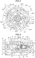
Fig. 1 is a cross-sectional view illustrating an entire configuration in a valve opening and closing timing control apparatus; -
Fig. 2 is a sectional view taken along line II-II inFig. 1 ; -
Fig. 3 is a sectional view illustrating a spool in a neutral position; -
Fig. 4 is a sectional view illustrating a spool in an advance angle position; -
Fig. 5 is a sectional view illustrating a spool in a retard angle position; -
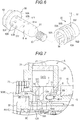
Fig. 6 is an exploded perspective view illustrating a bolt body and a sleeve; -
Fig. 7 is a sectional view illustrating a position of a rear connecting pin; -
Fig. 8 is a sectional view illustrating a position of a front connecting pin; -
Fig. 9 is an exploded perspective view illustrating an engagement of the front connecting pin; and -
Fig. 10 is an exploded perspective view illustrating an engagement of the rear connecting pin. - Hereinafter, an embodiment disclosed here will be described with reference to drawings.
- As illustrated in
Fig. 1 to Fig. 3 , a valve opening and closing timing control apparatus A is configured to include anexternal rotor 20 as a driving side rotor, aninternal rotor 30 as a driven side rotor, and asolenoid control valve 40 controlling a hydraulic oil as a working fluid. - The internal rotor 30 (one example of the driven side rotor) is disposed coaxially with a rotary axis X of an
intake camshaft 5, and is screwed and connected to theintake camshaft 5 by a connectingbolt 50 so as to rotate integrally. The external rotor 20 (one example of the driving side rotor) is disposed coaxially with the rotary axis X, and is relatively rotatably supported to theinternal rotor 30 by containing theinternal rotor 30. Theexternal rotor 20 synchronously rotates with acrankshaft 1 of an engine E as an internal combustion engine. - The
solenoid control valve 40 is provided with anelectromagnetic solenoid 44 supported by the engine E, and is provided with aspool 41 and aspool spring 42 accommodated in aspool chamber 51 S of the connectingbolt 50. - The
electromagnetic solenoid 44 is provided with aplunger 44a disposed at the coaxial core with the rotary axis X so as to abut on an outer end portion of thespool 41, and sets the amount of projection of theplunger 44a to set an operation position of thespool 41 by control of electric power to be supplied to the inside of a solenoid. Thereby, a relative rotational phase of theexternal rotor 20 and theinternal rotor 30 is set by controlling the hydraulic oil (one example of the working fluid). Therefore, control of an opening and closing timing of anintake valve 5V is realized. - Engine and the valve opening and closing timing control apparatus.
- The engine E (one example of the internal combustion engine) of
Fig. 1 indicates an engine that is provided in a vehicle such as a passenger car. The engine E accommodates apiston 3 in the inside of a cylinder bore in acylinder block 2 of the upper position, and is configured with four-cycle type to connect thepiston 3 and thecrankshaft 1 with a connectingrod 4. Theintake camshaft 5 opening and closing theintake valve 5V and an exhaust camshaft (not illustrated) are provided in upper side of the engine E. - In an
engine constituting member 10 rotatably supporting theintake camshaft 5, asupply flow passage 8 is formed to supply the hydraulic oil from a hydraulic pump P (one example of the fluid pressure pump) driven by the engine E. The hydraulic pump P supplies lubricating oil stored in the oil pan of the engine E to thesolenoid control valve 40 as the hydraulic oil (one example of the working fluid) via thesupply flow passage 8. - A
timing chain 7 is wound over anoutput sprocket 6 formed in thecrankshaft 1 of the engine E and thetiming sprocket 22S of theexternal rotor 20. Thereby, theexternal rotor 20 synchronously rotates with thecrankshaft 1. A sprocket is provided to the front end of the exhaust camshaft of exhaust side, and thetiming chain 7 is wound in the sprocket. - As illustrated in
Fig. 2 , theexternal rotor 20 rotates toward a driving rotational direction S by the driving force from thecrankshaft 1. The direction in which theinternal rotor 30 is relatively rotated in the same direction as the driving rotational direction S with respect to theexternal rotor 20 is referred to as an advance angle direction Sa, and the reverse direction thereof is referred to as a retard angle direction Sb. In the valve opening and closing timing control apparatus A, relationship between thecrankshaft 1 and theintake camshaft 5 is set so as to increase an intake air compression ratio in accordance with increase of the amount of displacement when the relative rotational phase is displaced in the advance angle direction Sa, and so as to reduce the intake air compression ratio in accordance with the increase of the amount of displacement when the relative rotational phase is displaced in the retard angle direction Sb. - Although the valve opening and closing timing control apparatus A is provided in the
intake camshaft 5 in the embodiment, the valve opening and closing timing control apparatus A may be provided in the exhaust camshaft, or may be provided in both of theintake camshaft 5 and the exhaust camshaft. - The
external rotor 20 includes the external rotormain body 21, afront plate 22, and arear plate 23, and these portions are integrated by engagement of a plurality offastening bolts 24. Thetiming sprocket 22S is formed on an outer periphery of thefront plate 22. Anintermediate member 9 is disposed on an inner periphery of thefront plate 22, and abolt head 52 of the connectingbolt 50 is crimped with respect to theintermediate member 9. Therefore, theintermediate member 9, the internal rotormain body 31, and theintake valve 5V are integrated. - A plurality of projecting
portions 21 T projecting towards the inside in a radial direction is integrally formed in the external rotormain body 21. Theinternal rotor 30 includes the cylindrical internal rotormain body 31 which is brought into close contact with the projectingportion 21T of the external rotormain body 21, and fourvane portions 32 which project towards the outside in the radial direction from the outer periphery of the internal rotormain body 31 so as to come into contact with an inner peripheral surface of the external rotormain body 21. - Thereby, the
external rotor 20 contains theinternal rotor 30, and the plurality of the fluid pressure chambers C are formed on the outer periphery side of the internal rotormain body 31 at an intermediate position of the projectingportion 21T adjacent to each other in the rotation direction. These fluid pressure chambers C are partitioned by thevane portion 32, and an advance angle chamber Ca and a retard angle chamber Cb are partitioned and formed. A plurality of advance angle flow passages 33 (four) communicating with the advance angle chamber Ca are formed in theinternal rotor 30, and a plurality of retard angle flow passages 34 (four) communicating with the retard angle chamber Cb are formed in theinternal rotor 30. - As illustrated in
Fig. 1 , atorsion spring 28 assisting a displacement of the relative rotational phase between theexternal rotor 20 and the internal rotor 30 (hereinafter, referred to as the relative rotational phase) to the advance angle direction Sa by the action of biasing force from most retarded angle phase to the advance angle direction Sa is provided over theexternal rotor 20 and theintermediate member 9. - A locking mechanism L locking (fixing) the relative rotational phase between the
external rotor 20 and theinternal rotor 30 in the most retarded angle phase is provided. The locking mechanism L is configured to be provided with a locking member 26 supported freely movable in the direction along the rotary axis X with respect to the onevane portion 32, a locking spring (not illustrated) projected and biased the locking member 26, and a locking recess portion (not illustrated) formed on therear plate 23. The locking mechanism L may be configured to be provided with the locking member 26 guided so as to be moved along a radial direction. - The relative rotational phase reaches the most retarded angle phase. Therefore, the locking member 26 is engaged with the locking recess portion by the biasing force of the locking spring, and the locking mechanism L serves to maintain the relative rotational phase to the most retarded angle phase. In a case where the advance
angle flow passage 33 communicates with the locking recess portion, and the hydraulic oil is supplied to the advanceangle flow passage 33, the locking mechanism L is also configured to perform lock releasing to detach the locking member 26 from the locking recess portion by a hydraulic oil pressure. - As illustrated in
Fig. 1 to Fig. 6 , the connectingbolt 50 is provided with abolt body 51 of which a portion is cylindrical, acylindrical sleeve 55 fitted in a cylindrical portion of thebolt body 51, and aregulation pin 57 as an engagement member positioning these portions. - In the
intake camshaft 5, a female threadedportion 5S is formed around the rotary axis X, and an inside space of theshaft 5T as a larger diameter than the female threadedportion 5S is formed so that thesleeve 55 is tightly fitted. The inside space of theshaft 5T communicates with thesupply flow passage 8 as described above. The hydraulic oil is supplied from the hydraulic pump P to the inside space of theshaft 5T. - The
bolt head 52 is formed on the outer end portion of thebolt body 51 and a male threadedportion 53 is formed on an inner end portion. Based on the configuration, the male threadedportion 53 of thebolt body 51 is screwed to the female threadedportion 5S of theintake camshaft 5, and theinternal rotor 30 is fastened to theintake camshaft 5 by rotational operation of thebolt head 52. In the fastening state, an inner end side of the outer periphery (male screw side) of thesleeve 55 being fitted in thebolt body 51 is in close contact with the inner peripheral surface of the inside space of theshaft 5T, and the outer peripheral surface of an outer end side (bolt head side) of thesleeve 55 is in close contact with the inner peripheral surface of the internal rotormain body 31. - In the inside of the
bolt body 51, the hole-shaped inner space is formed towards in the direction of the male threadedportion 53 from thebolt head 52, aretainer 54 is press-fitted and fixed to the inner space. Therefore, the inner space is divided by theretainer 54, and thespool chamber 51 S and ahydraulic oil chamber 51 T as a fluid chamber are formed in a non-communicated state. - The
spool chamber 51 S is formed in a cylinder inner surface shape and thespool 41 is reciprocally movably accommodated along the rotary axis X in thespool chamber 51 S. Therefore, thespool spring 42 is disposed between the inside end of thespool 41 and theretainer 54. Thereby, thespool 41 is biased so as to project in the direction of the outer end side (direction of the bolt head 52). - In the
bolt body 51, the plurality of acquisition flowpassages 51m communicating thehydraulic oil chamber 51 T and the inside space of theshaft 5T are formed and the plurality ofintermediate flow passages 51n are formed between thehydraulic oil chamber 51 T and the outer peripheral surface of thebolt body 51. - A check valve CV is provided in the flow passage sending the hydraulic oil from the
acquisition flow passage 51 m to theintermediate flow passage 51 n in thehydraulic oil chamber 51 T. This check valve CV is configured with aball holder 61, acheck spring 62, and acheck ball 63. - In this check valve CV, the
check spring 62 is disposed between theretainer 54 and thecheck ball 63 and thecheck ball 63 is in pressure contact with an opening of theball holder 61 by the biasing force of thecheck spring 62 to close the flow passage. Anoil filter 64 removing dust from the hydraulic oil flowing toward thecheck ball 63 is provided in theball holder 61. - In a case where the pressure of the hydraulic oil supplied to the
hydraulic oil chamber 51 T exceeds the predetermined value, the check valve CV opens the flow passage against the biasing force of thecheck spring 62 and in a case where the pressure is decreased less than the predetermined value, the check valve CV closes the flow passage by the biasing force of thecheck spring 62. By this operation, when the pressure of the hydraulic oil is decreased, reverse flow of the hydraulic oil from the advance angle chamber Ca or the retard angle chamber Cb is prevented and variation of the phase of the valve opening and closing timing control apparatus A is suppressed. Even in a case where the pressure of a downstream side of the check valve CV exceeds the predetermined value, this check valve CV performs closing operation. - As described above, the
solenoid control valve 40 is provided with thespool 41, thespool spring 42, and theelectromagnetic solenoid 44. - A plurality of
pump ports 50P communicating thespool chamber 51 S and the outer peripheral surface of thebolt body 51 are formed as a through hole in thebolt body 51. The plurality ofadvance angle ports 50A and a plurality ofretard angle ports 50B communicating thespool chamber 51 S and the outer peripheral surface of thesleeve 55 are formed as the through hole over thebolt body 51 and thesleeve 55 in the connectingbolt 50. - The
advance angle port 50A, thepump port 50P, and theretard angle port 50B are disposed in the inner end side from the outer end side of the connectingbolt 50 in this order. Theadvance angle port 50A and theretard angle port 50B in the direction as viewed along the rotary axis X are formed in the overlapping positions with each other and thepump port 50P is formed in a position that does not overlap with these ports. - On the outer periphery of the
sleeve 55, an annular groove is formed in which the plurality of theadvance angle ports 50A communicate and the plurality of theadvance angle ports 50A communicate with the plurality of the advanceangle flow passages 33 from the annular groove. In the same way, on the outer periphery of thesleeve 55, the annular groove is formed in which the plurality of theretard angle ports 50B communicate and the plurality of theretard angle ports 50B communicate with the plurality of the retardangle flow passages 34 from the annular groove. Furthermore, a plurality ofintroduction flow passages 56 communicating theintermediate flow passage 51n and thepump port 50P are formed in a groove shape on the inner peripheral surface of thesleeve 55. - That is, the
sleeve 55 is shaped at a dimension reaching a position covering theintermediate flow passage 51 n from thebolt head 52 of thebolt body 51 and theintroduction flow passage 56 is formed in a region avoiding theadvance angle port 50A and theretard angle port 50B. - A first engaging
portion 51f as a hole with a bag shape is formed at a position deviated from a press-fitted and fixed position of theretainer 54 in the direction along the rotary axis X in thebolt body 51, a secondengaging portion 55f having a hole shape penetrating in the radial direction is formed, and theregulation pin 57 to engage with both portions is provided in thesleeve 55. Theregulation pin 57 is press-fitted and fixed to the first engagingportion 51 f. - Specifically, the second
engaging portion 55f is formed in a long hole shape of which the direction along the rotary axis X is larger than the direction perpendicular thereto. A slight gap to allow relative movement in the direction along the rotary axis X of thebolt body 51 and thesleeve 55 is formed between the secondengaging portion 55f and theregulation pin 57 from the configuration. - That is, the
sleeve 55 is configured to be movable respectively only by an amount corresponding to the gap between the secondengaging portion 55f and theregulation pin 57 in the direction along the rotary axis X with respect to thebolt body 51, while maintaining a relative posture of the rotation around the rotary axis X of thebolt body 51 and thesleeve 55. Thereby, by the pressure of the hydraulic oil acting at the end of thesleeve 55 from thehydraulic oil chamber 51 T, theentire sleeve 55 is moved in the direction of the outer end side, the end of the outer end side of thesleeve 55 is in close contact to move until the end abuts on the back surface of thebolt head 52 of the bolt body 51 (portion of the driven side rotor), and thus the leakage of the hydraulic oil at this portion is suppressed. - Thereby, the relative posture of the rotation around the rotary axis X of the
bolt body 51 and thesleeve 55 and a relative position thereof along the rotary axis X are determined. Accordingly, the hydraulic oil from thehydraulic oil chamber 51T may be supplied to thepump port 50P via theacquisition flow passage 51 m, the check valve CV, theintermediate flow passage 51 n, and theintroduction flow passage 56. - The
spool 41 forms an abutting surface on which theplunger 44a abuts on the outer end side, formsland portions 41 A at two positions in the direction along the rotary axis X, and forms agroove portion 41 B at an intermediate position of theseland portions 41 A. Thespool 41 is formed in a hollow and adrain hole 41 D is formed on a projecting end of thespool 41. Thespool 41 abuts on astopper 43 provided on an inner peripheral opening of the outer end side of the connectingbolt 50, so that a position of a projecting side is determined. - The
solenoid control valve 40 causes theplunger 44a to abut on the abutting surface of thespool 41 and controls the amount of projection. Therefore, as illustrated inFig. 3 ,Fig. 4, and Fig.5 , thesolenoid control valve 40 is configured to be capable of setting thespool 41 at a neutral position, a retard angle position, and an advance angle position. - The
spool 41 is set at the neutral position illustrated inFig. 3 , so that theadvance angle port 50A and theretard angle port 50B are closed at the same time by a pair of theland portions 41A of thespool 41. As a result, the feeding and discharging of the hydraulic oil to the advance angle chamber Ca and the retard angle chamber Cb is not preformed and the phase of the valve opening and closing timing control apparatus A is maintained. - The
plunger 44a is retracted (operated outwards) on the basis of the neutral position by the control of theelectromagnetic solenoid 44, so that thespool 41 is set at the advance angle position illustrated inFig. 4 . Thepump port 50P communicates with theadvance angle port 50A via thegroove portion 41 B at the advance angle position. At the same time, theretard angle port 50B communicates with thespool chamber 51 S from the inner end of thespool 41. Thereby, the hydraulic oil is supplied to the advance angle chamber Ca, the hydraulic oil flows to the inside of thespool 41 from the retard angle chamber Cb, and the hydraulic oil is discharged from thedrain hole 41 D (flow of the hydraulic oil is illustrated by an arrow inFig. 4 ). As a result, a rotation phase of theintake camshaft 5 is displaced in the advance angle direction Sa. The retard angle position coincides with the position in which thespool 41 abuts on thestopper 43 by the biasing force of thespool spring 42. - In a state where the locking mechanism L is in a lock state, the
spool 41 is set at the advance angle position and in a case where the hydraulic oil is supplied to the advanceangle flow passage 33, the hydraulic oil is supplied to the locking recess portion of the locking mechanism L from the advanceangle flow passage 33. Therefore, the locking member 26 is detached from the locking recess portion and the lock state of the locking mechanism L is released. - The
plunger 44a is projected (operated inwards) on the basis of the neutral position by the control of theelectromagnetic solenoid 44, so that thespool 41 is set at the retard angle position illustrated inFig. 5 . Thepump port 50P communicates with theretard angle port 50B via thegroove portion 41 B at the retard angle position. At the same time, theadvance angle port 50A communicates with a drain space (space continued to the outer end side from thespool chamber 51 S). Thereby, the hydraulic oil is supplied to the retard angle chamber Cb and at the same time the hydraulic oil is discharged from the advance angle chamber Ca (flow of the hydraulic oil is illustrated by an arrow inFig. 5 ). As a result, the rotation phase of theintake camshaft 5 is displaced in the retard angle direction Sb. - The valve opening and closing timing control apparatus A is provided with a front position determination unit FB that determines a positional relationship around the rotary axis X of the
internal rotor 30 and theintermediate member 9, and a rear position determination unit RB that determines the positional relationship around the rotary axis X of theinternal rotor 30 and theintake camshaft 5. The front position determination unit FB is provided with a frontengaging pin 71 in a posture parallel to the rotary axis X, and the rear position determination unit RB is provided with a rearengaging pin 72 in a posture parallel with the rotary axis X. An aluminum alloy is used in the internal rotormain body 31, and a steel material is used in theintermediate member 9 and the intake camshaft. - As illustrated in
Figs. 7 to 10 , acylindrical portion 9A and a connectingwall portion 9B are integrally formed in theintermediate member 9, and acircular opening portion 9C is formed around the rotary axis X in the connectingwall portion 9B. A connectingcontact surface 9s is formed on a surface facing the internal rotormain body 31 of the connectingwall portion 9B. Anabutting contact surface 5p is formed on the surface facing the internal rotormain body 31 of theintake camshaft 5. - As illustrated in
Figs. 8 and9 , afront contact surface 31f is formed in a recessed shape in which the connectingwall portion 9B is fitted, on a side where theintermediate member 9 is disposed of the internal rotormain body 31, and the connectingcontact surface 9s of the connectingwall portion 9B is disposed in a contact state to thefront contact surface 31f. As illustrated inFigs. 7 and10 , arear contact surface 31 r is formed in a recessed shape in which theintake camshaft 5 is fitted, on a side where theintake camshaft 5 is disposed of the internal rotormain body 31, and theabutting contact surface 5p of theintake camshaft 5 is disposed in a contact state to therear contact surface 31 r. - As illustrated in
Fig. 7 and10 , the advanceangle flow passage 33 is configured with a first advanceangle flow passage 33a that is formed along a boundary part between thefront contact surface 31f of the internal rotormain body 31 and the connectingcontact surface 9s of theintermediate member 9 in the radial direction, a second advanceangle flow passage 33b that is formed in the internal rotormain body 31 in a posture parallel to the rotary axis X from the outer end position of the first advanceangle flow passage 33a, and a third advanceangle flow passage 33c that is formed in the internal rotormain body 31 from the second advanceangle flow passage 33b in the radial direction. - Thereby, a portion of four first advance
angle flow passages 33a is formed in a groove shape along the radial direction on the connectingcontact surface 9s. A portion of four first advanceangle flow passages 33a is formed in a groove shape along the radial direction on thefront contact surface 31f of the internal rotormain body 31. The second advanceangle flow passage 33b and the third advanceangle flow passage 33c communicating with the first advanceangle flow passage 33a are formed in the inside of the internal rotormain body 31. - A front first hole portion FH1 into which one end of the front
engaging pin 71 is press-fitted (fitted) is formed on the connectingcontact surface 9s of the connectingwall portion 9B, and a deformation absorbing unit R which is configured with a slit continuing to cut and open the front first hole portion FH1 in the direction of theopening portion 9C is formed. A front second hole portion FH2 in which the other end of the frontengaging pin 71 is inserted is formed on thefront contact surface 31f. In this manner, the front position determination unit FB is provided with the frontengaging pin 71, the front first hole portion FH1, the front second hole portion FH2, and the deformation absorbing unit R. The deformation absorbing unit R, without being limited to the slit, may be formed as the space with a non-slit shape extending outward of the front first hole portion FH1 (space with the groove shape continuing to the outer periphery of the front first hole portion FH1) from the outer periphery of the front first hole portion FH1. - An inner diameter of the front first hole portion FH1 is set to a value slightly smaller than an outer diameter of the front
engaging pin 71, the outer peripheral surface of the frontengaging pin 71 is in close contact with the inner peripheral surface of the front first hole portion FH1 (becomes a tight-fitted state) by the press-fitting, and a state that the frontengaging pin 71 is fixed to theintermediate member 9 is maintained. In a case where the frontengaging pin 71 is fitted in the front first hole portion FH1, theintermediate member 9 in the vicinity of the front first hole portion FH1 is deformed, and thus a portion of theopening portion 9C is inflated toward the rotary axis X in some cases. - The deformation absorbing unit R is formed to be the slit shape in order to suppress an inconvenience, in a case of being press-fitted in order to fit the front
engaging pin 71, internal stress of theintermediate member 9 is applied in a direction to expand a width of the slit of the deformation absorbing unit R, and thus the deformation inflating the inner periphery of theopening portion 9C is suppressed. Thereby, the fitting accuracy of thesleeve 55 which is disposed in close contact with the inner periphery of theopening portion 9C is maintained in good state. - The inner diameter of the front second hole portion FH2 is set to a value slightly larger than the outer diameter of the front
engaging pin 71, and is configured so that the slight gap is formed between the inner surface of the front second hole portion FH2 and the outer surface of the frontengaging pin 71 in an inserted state. - Furthermore, the front
engaging pin 71 is a pin of which a sectional shape is formed in a circular shape, and is formed in noncircular shape tapering the shape of anend position 33t of the first advanceangle flow passage 33a (reducing the width by the outer periphery side of the intermediate member 9) formed on the connectingcontact surface 9s in order to suppress an erroneous insertion of the frontengaging pin 71. Such a shape of theend position 33t is different from the sectional shape of the front engaging pin 71 (sectional shape viewed in the direction along the rotary axis X). Therefore, it is not possible to insert the frontengaging pin 71 in the portion of theend position 33t, and thus the inconvenience of mistaking the insertion position of the frontengaging pin 71 is eliminated. - As illustrated in
Figs. 7 and10 , a rear first hole portion RH1 into which one end of the rear engagingpin 72 is press-fitted (fitted) is formed on theabutting contact surface 5p in contact with the internal rotormain body 31 of theintake camshaft 5, and the deformation absorbing unit R is formed in the groove of the posture along the rotary axis X on the outer peripheral surface of theintake camshaft 5 that becomes a vicinity position of the rear first hole portion RH1. A rear second hole portion RH2 that is inserted in the other end of the rear engagingpin 72 is formed on therear contact surface 31r in contact with the abuttingcontact surface 5p of the internal rotormain body 31. - In this manner, the rear position determination unit RB is configured with the rear engaging
pin 72, the rear first hole portion RH1, the rear second hole portion RH2, and the deformation absorbing unit R. - An inner diameter of the rear first hole portion RH1 is set to a value slightly smaller than an outer diameter of the rear engaging
pin 72, the outer peripheral surface of the rear engagingpin 72 is in close contact with the inner peripheral surface of the rear first hole portion RH1 (becomes the tight-fitted state) by the press-fitting, and a state that therear engaging pin 72 is fixed to theintake camshaft 5 is maintained. In a case where therear engaging pin 72 is press-fitted into the rear first hole portion RH1, theintake camshaft 5 in the vicinity of the rear first hole portion RH1 is deformed, and thus a portion of the outer periphery is inflated outward (direction away from the rotary axis X) in some cases. - The deformation absorbing unit R in the groove shape is formed to the outer periphery of the
intake camshaft 5 in order to eliminate the inconvenience, in a case where therear engaging pin 72 is press-fitted, internal stress of theintake camshaft 5 is applied in a direction to expand a width of the groove of the deformation absorbing unit R, and thus the deformation inflating the inner periphery is suppressed. Thereby, although a portion of the internal rotormain body 31 is externally fitted to the outer periphery of theintake camshaft 5, a good fitted state is maintained. - The inner diameter of the rear second hole portion RH2 is set to a value slightly larger than the outer diameter of the rear engaging
pin 72, and is configured so that the slight gap is formed between the inner surface of the rear second hole portion RH2 and the outer surface of the frontengaging pin 71 in an inserted state. - According to such a configuration, in a case of assembling the valve opening and closing timing control apparatus A, the front
engaging pin 71 is press-fitted and fixed (fitted) to the front first hole portion FH1 of theintermediate member 9, and therear engaging pin 72 is press-fitted and fixed (fitted) to the rear first hole portion RH1 of theintake camshaft 5. Thereby, the frontengaging pin 71 and therear engaging pin 72 can be stably held. - In a case of assembling the valve opening and closing timing control apparatus A, the front
engaging pin 71 is inserted in the front second hole portion FH2 of the internal rotormain body 31, and thus a relative position around the rotary axis X between the internal rotormain body 31 and theintermediate member 9 is determined. In the valve opening and closing timing control apparatus A, although thesleeve 55 is disposed to be fitted in theopening portion 9C of theintermediate member 9, as described above, even if the frontengaging pin 71 is press-fitted, a phenomenon of deforming so as to inflate the inner periphery of theopening portion 9C is suppressed, and thus thesleeve 55 can be surely inserted. Furthermore, a flow passage that supplies and discharges the hydraulic oil is not narrowed by the deformation. - Furthermore, at the time of the assembly, the
rear engaging pin 72 is inserted in the rear second hole portion RH2 of the internal rotormain body 31, and thus a relative position around the rotary axis X between theintake camshaft 5 and the internal rotormain body 31 is determined. In the valve opening and closing timing control apparatus A, although a portion of the internal rotormain body 31 is externally fitted to the outer periphery of theintake camshaft 5, a phenomenon of deforming so as to inflate the outer periphery of theintake camshaft 5 is eliminated, and thus a work for an external fitting is smoothly performed and an accuracy of the fitting portion is highly maintained. - In this state, the connecting
bolt 50 is inserted in theintermediate member 9 and the internal rotormain body 31, the male threadedportion 53 of the connectingbolt 50 is screwed to the female threadedportion 5S of theintake camshaft 5, and the connectingbolt 50 is fastened by the rotation operation. Therefore, the assembly is completed. In the assembly, work of the process such as thesleeve 55 being externally fitted to the connectingbolt 50 and thespool 41 being set to thespool chamber 51 S is performed in advance. - Specifically, in this configuration, even in a case where the press-fitted member is deformed larger than expected as a case where the outer diameter of the front
engaging pin 71 is greater than a design value against the inner diameter of the front first hole portion FH1, or as a case where the outer diameter of the rear engagingpin 72 is greater than a design value against the inner diameter of the rear first hole portion RH1, reasonable assembly is realized. Accordingly, it is not necessary to increase the accuracy between the front position determination unit FB and the rear position determination unit RB, and thus it is easy to manufacture. - This disclosure may be configured as follows except for the above-described embodiment (those having the same functions as the embodiment are designated with the common numbers and reference numerals as the embodiment).
- (a) For example, in the valve opening and closing timing control apparatus A configured to dispose the intermediate member with a ring shape between the internal rotor
main body 31 and the intake camshaft 5 (it may be the exhaust camshaft), the configuration of this disclosure may be applied to the position determining unit that performs positioning in the rotation direction between the intermediate member with the ring shape and the internal rotormain body 31, or to the position determining unit that performs positioning in the rotation direction between the member with the ring shape and theintake camshaft 5. - (b) The deformation absorbing unit R may be any of the inner periphery and the outer periphery of the member in which a first hole portion is formed. The deformation absorbing unit R may be formed respectively on the inner periphery and the outer periphery of the member.
- (c) In a case where an engaging pin is press-fitted into the member, insofar as a portion of the member is configured to suppress the inflated deformation, the deformation absorbing unit R may be the hole portion or the recessed portion formed in the vicinity of a first engaging hole portion, without being limited to the slit or the groove. The deformation absorbing unit R may be formed as a space (space with non-slit shape) which is formed in a groove shape along the first hole portion to the outer periphery of the first hole portion, by extending outward from the outer periphery of the first hole portion.
- This disclosure may be used for the valve opening and closing timing control apparatus positioning a plurality of members disposed along the rotary axis by the engaging pin.
- The principles, preferred embodiment and mode of operation of the present invention have been described in the foregoing specification. However, the invention which is intended to be protected is not to be construed as limited to the particular embodiments disclosed. Further, the embodiments described herein are to be regarded as illustrative rather than restrictive. Variations and changes may be made by others, and equivalents employed, without departing from the spirit of the present invention. Accordingly, it is expressly intended that all such variations, changes and equivalents which fall within the spirit and scope of the present invention as defined in the claims, be embraced thereby.
- It is explicitly stated that all features disclosed in the description and/or the claims are intended to be disclosed separately and independently from each other for the purpose of original disclosure as well as for the purpose of restricting the claimed invention independent of the composition of the features in the embodiments and/or the claims. It is explicitly stated that all value ranges or indications of groups of entities disclose every possible intermediate value or intermediate entity for the purpose of original disclosure as well as for the purpose of restricting the claimed invention, in particular as limits of value ranges.
Claims (4)
- A valve opening and closing timing control apparatus (A) comprising:a driving side rotor (20) that synchronously rotates with a crankshaft (1) of an internal combustion engine (E);a driven side rotor (30) that is disposed coaxially with a rotary axis (X) of the driving side rotor (20) and synchronously rotates with a camshaft (5) for valve opening and closing;a connecting bolt (50) that is disposed coaxially with the rotary axis (X), and connects the driven side rotor (30) to the camshaft (5); anda position determination unit (FB, RB) that performs positioning between the driven side rotor (30) and the camshaft (5), or in a case where an intermediate member (9) is provided between the driven side rotor (30) and the camshaft (5), between the driven side rotor (30) and the intermediate member (9), or between the camshaft (5) and the intermediate member (9),wherein the position determination unit (FB, RB) includes an engaging pin (71, 72) that is in a posture parallel to the rotary axis (X), a first hole portion (FH1, RH1) into which one end of the engaging pin (71, 72) is fitted is provided in any one of two members performing the positioning, a second hole portion (FH2, RH2) in which the other end of the engaging pin (71, 72) is inserted is provided in the other one, and a deformation absorbing unit (R) that suppresses deformation at a time when the engaging pin (71, 72) is fitted is provided in the vicinity of the first hole portion (FH1, RH1).
- The valve opening and closing timing control apparatus (A) according to claim 1,
wherein the deformation absorbing unit (R) is configured with a groove that is formed in a posture parallel to the rotary axis (X) at a position adjacent to an outer periphery of the first hole portion (FH1, RH1). - The valve opening and closing timing control apparatus (A) according to claim 1,
wherein the deformation absorbing unit (R) is configured with a space extending outward from an outer periphery of the first hole portion (FH1, RH1). - The valve opening and closing timing control apparatus (A) according to any one of claims 1 to 3,
wherein a flow passage (33,34) that supplies and discharges a hydraulic oil to an advance angle chamber (Ca) or a retard angle chamber (Cb) formed between the driving side rotor (20) and the driven side rotor (30) is formed in the driving side rotor (20) or the intermediate member (9), and
wherein a sectional shape of the flow passage (33, 34) along the rotary axis direction is different from a sectional shape of the engaging pin (71, 72).
Applications Claiming Priority (1)
| Application Number | Priority Date | Filing Date | Title |
|---|---|---|---|
| JP2015249013A JP2017115600A (en) | 2015-12-21 | 2015-12-21 | Valve opening timing control device |
Publications (2)
| Publication Number | Publication Date |
|---|---|
| EP3187704A1 true EP3187704A1 (en) | 2017-07-05 |
| EP3187704B1 EP3187704B1 (en) | 2018-09-26 |
Family
ID=57389306
Family Applications (1)
| Application Number | Title | Priority Date | Filing Date |
|---|---|---|---|
| EP16199975.0A Not-in-force EP3187704B1 (en) | 2015-12-21 | 2016-11-22 | Valve opening and closing timing control apparatus |
Country Status (4)
| Country | Link |
|---|---|
| US (1) | US10174646B2 (en) |
| EP (1) | EP3187704B1 (en) |
| JP (1) | JP2017115600A (en) |
| CN (1) | CN106894857B (en) |
Families Citing this family (2)
| Publication number | Priority date | Publication date | Assignee | Title |
|---|---|---|---|---|
| JP7231335B2 (en) * | 2018-04-18 | 2023-03-01 | 株式会社ミクニ | valve timing changer |
| JP7021658B2 (en) * | 2019-03-25 | 2022-02-17 | 株式会社デンソー | Valve timing adjuster |
Citations (9)
| Publication number | Priority date | Publication date | Assignee | Title |
|---|---|---|---|---|
| US6012419A (en) * | 1996-08-09 | 2000-01-11 | Denso Corporation | Rotational phase adjusting apparatus having seat for drill-machining |
| US6269785B1 (en) * | 1998-01-29 | 2001-08-07 | Denso Corporation | Variable valve timing mechanism |
| JP2002295208A (en) | 2001-03-29 | 2002-10-09 | Denso Corp | Valve timing adjustment device |
| US20060042581A1 (en) * | 2004-08-31 | 2006-03-02 | Hitachi, Ltd. | Valve timing control apparatus and its assembling method |
| JP2006183590A (en) | 2004-12-28 | 2006-07-13 | Denso Corp | Valve timing adjustment device |
| JP2007127057A (en) * | 2005-11-04 | 2007-05-24 | Mikuni Corp | Mounting structure of valve timing adjustment device |
| US20110061616A1 (en) * | 2009-09-16 | 2011-03-17 | Hitachi Automotive Systems, Ltd. | Valve Timing Control Apparatus for Internal Combustion Engine, and Method of Producing Same |
| JP2012172558A (en) | 2011-02-18 | 2012-09-10 | Aisin Seiki Co Ltd | Valve opening/closing timing control device |
| US20120285407A1 (en) * | 2011-05-10 | 2012-11-15 | Hitachi Automotive Systems, Ltd. | Variable valve timing control apparatus of internal combustion engine |
Family Cites Families (2)
| Publication number | Priority date | Publication date | Assignee | Title |
|---|---|---|---|---|
| DE19944535C1 (en) | 1999-09-17 | 2001-01-04 | Daimler Chrysler Ag | Cam shaft adjuster for internal combustion engines has control slider with central return bore and controllable housing connections connectable to supply connection on return side |
| JP5321926B2 (en) | 2011-02-18 | 2013-10-23 | アイシン精機株式会社 | Valve timing control device |
-
2015
- 2015-12-21 JP JP2015249013A patent/JP2017115600A/en active Pending
-
2016
- 2016-09-27 US US15/277,173 patent/US10174646B2/en active Active
- 2016-11-02 CN CN201610957557.3A patent/CN106894857B/en not_active Expired - Fee Related
- 2016-11-22 EP EP16199975.0A patent/EP3187704B1/en not_active Not-in-force
Patent Citations (9)
| Publication number | Priority date | Publication date | Assignee | Title |
|---|---|---|---|---|
| US6012419A (en) * | 1996-08-09 | 2000-01-11 | Denso Corporation | Rotational phase adjusting apparatus having seat for drill-machining |
| US6269785B1 (en) * | 1998-01-29 | 2001-08-07 | Denso Corporation | Variable valve timing mechanism |
| JP2002295208A (en) | 2001-03-29 | 2002-10-09 | Denso Corp | Valve timing adjustment device |
| US20060042581A1 (en) * | 2004-08-31 | 2006-03-02 | Hitachi, Ltd. | Valve timing control apparatus and its assembling method |
| JP2006183590A (en) | 2004-12-28 | 2006-07-13 | Denso Corp | Valve timing adjustment device |
| JP2007127057A (en) * | 2005-11-04 | 2007-05-24 | Mikuni Corp | Mounting structure of valve timing adjustment device |
| US20110061616A1 (en) * | 2009-09-16 | 2011-03-17 | Hitachi Automotive Systems, Ltd. | Valve Timing Control Apparatus for Internal Combustion Engine, and Method of Producing Same |
| JP2012172558A (en) | 2011-02-18 | 2012-09-10 | Aisin Seiki Co Ltd | Valve opening/closing timing control device |
| US20120285407A1 (en) * | 2011-05-10 | 2012-11-15 | Hitachi Automotive Systems, Ltd. | Variable valve timing control apparatus of internal combustion engine |
Also Published As
| Publication number | Publication date |
|---|---|
| CN106894857B (en) | 2019-05-31 |
| US10174646B2 (en) | 2019-01-08 |
| EP3187704B1 (en) | 2018-09-26 |
| US20170175593A1 (en) | 2017-06-22 |
| CN106894857A (en) | 2017-06-27 |
| JP2017115600A (en) | 2017-06-29 |
Similar Documents
| Publication | Publication Date | Title |
|---|---|---|
| EP3165723B1 (en) | Valve opening and closing timing control apparatus | |
| JP6834382B2 (en) | Valve opening / closing timing control device | |
| US9470120B2 (en) | Valve timing control apparatus | |
| US8910604B2 (en) | Valve timing control device | |
| US8910605B2 (en) | Valve timing control device | |
| JP2018138779A (en) | Valve opening/closing timing control device | |
| US11041412B2 (en) | Valve timing controller | |
| EP3187704B1 (en) | Valve opening and closing timing control apparatus | |
| EP3321479B1 (en) | Valve opening/closing timing control apparatus | |
| JP6769253B2 (en) | Valve opening / closing timing control device | |
| CN106062323B (en) | valve timing control device | |
| EP3190274B1 (en) | Valve opening and closing timing control apparatus | |
| WO2018101059A1 (en) | Valve timing adjustment device, and method for manufacturing same | |
| US10132213B2 (en) | Valve opening and closing timing control apparatus | |
| US9617877B2 (en) | Valve opening and closing timing control device | |
| CN115461529A (en) | Working oil control valve and valve timing adjustment device | |
| US20210172346A1 (en) | Valve opening and closing timing control device | |
| JP2017089517A (en) | Valve open/close timing control device |
Legal Events
| Date | Code | Title | Description |
|---|---|---|---|
| PUAI | Public reference made under article 153(3) epc to a published international application that has entered the european phase |
Free format text: ORIGINAL CODE: 0009012 |
|
| 17P | Request for examination filed |
Effective date: 20170310 |
|
| AK | Designated contracting states |
Kind code of ref document: A1 Designated state(s): AL AT BE BG CH CY CZ DE DK EE ES FI FR GB GR HR HU IE IS IT LI LT LU LV MC MK MT NL NO PL PT RO RS SE SI SK SM TR |
|
| AX | Request for extension of the european patent |
Extension state: BA ME |
|
| GRAP | Despatch of communication of intention to grant a patent |
Free format text: ORIGINAL CODE: EPIDOSNIGR1 |
|
| INTG | Intention to grant announced |
Effective date: 20180425 |
|
| GRAS | Grant fee paid |
Free format text: ORIGINAL CODE: EPIDOSNIGR3 |
|
| GRAA | (expected) grant |
Free format text: ORIGINAL CODE: 0009210 |
|
| AK | Designated contracting states |
Kind code of ref document: B1 Designated state(s): AL AT BE BG CH CY CZ DE DK EE ES FI FR GB GR HR HU IE IS IT LI LT LU LV MC MK MT NL NO PL PT RO RS SE SI SK SM TR |
|
| REG | Reference to a national code |
Ref country code: GB Ref legal event code: FG4D |
|
| REG | Reference to a national code |
Ref country code: CH Ref legal event code: EP |
|
| REG | Reference to a national code |
Ref country code: AT Ref legal event code: REF Ref document number: 1046279 Country of ref document: AT Kind code of ref document: T Effective date: 20181015 |
|
| REG | Reference to a national code |
Ref country code: IE Ref legal event code: FG4D |
|
| REG | Reference to a national code |
Ref country code: DE Ref legal event code: R096 Ref document number: 602016006013 Country of ref document: DE |
|
| REG | Reference to a national code |
Ref country code: NL Ref legal event code: MP Effective date: 20180926 |
|
| PG25 | Lapsed in a contracting state [announced via postgrant information from national office to epo] |
Ref country code: FI Free format text: LAPSE BECAUSE OF FAILURE TO SUBMIT A TRANSLATION OF THE DESCRIPTION OR TO PAY THE FEE WITHIN THE PRESCRIBED TIME-LIMIT Effective date: 20180926 Ref country code: BG Free format text: LAPSE BECAUSE OF FAILURE TO SUBMIT A TRANSLATION OF THE DESCRIPTION OR TO PAY THE FEE WITHIN THE PRESCRIBED TIME-LIMIT Effective date: 20181226 Ref country code: NO Free format text: LAPSE BECAUSE OF FAILURE TO SUBMIT A TRANSLATION OF THE DESCRIPTION OR TO PAY THE FEE WITHIN THE PRESCRIBED TIME-LIMIT Effective date: 20181226 Ref country code: GR Free format text: LAPSE BECAUSE OF FAILURE TO SUBMIT A TRANSLATION OF THE DESCRIPTION OR TO PAY THE FEE WITHIN THE PRESCRIBED TIME-LIMIT Effective date: 20181227 Ref country code: RS Free format text: LAPSE BECAUSE OF FAILURE TO SUBMIT A TRANSLATION OF THE DESCRIPTION OR TO PAY THE FEE WITHIN THE PRESCRIBED TIME-LIMIT Effective date: 20180926 Ref country code: LT Free format text: LAPSE BECAUSE OF FAILURE TO SUBMIT A TRANSLATION OF THE DESCRIPTION OR TO PAY THE FEE WITHIN THE PRESCRIBED TIME-LIMIT Effective date: 20180926 |
|
| REG | Reference to a national code |
Ref country code: LT Ref legal event code: MG4D |
|
| PG25 | Lapsed in a contracting state [announced via postgrant information from national office to epo] |
Ref country code: HR Free format text: LAPSE BECAUSE OF FAILURE TO SUBMIT A TRANSLATION OF THE DESCRIPTION OR TO PAY THE FEE WITHIN THE PRESCRIBED TIME-LIMIT Effective date: 20180926 Ref country code: LV Free format text: LAPSE BECAUSE OF FAILURE TO SUBMIT A TRANSLATION OF THE DESCRIPTION OR TO PAY THE FEE WITHIN THE PRESCRIBED TIME-LIMIT Effective date: 20180926 Ref country code: AL Free format text: LAPSE BECAUSE OF FAILURE TO SUBMIT A TRANSLATION OF THE DESCRIPTION OR TO PAY THE FEE WITHIN THE PRESCRIBED TIME-LIMIT Effective date: 20180926 |
|
| REG | Reference to a national code |
Ref country code: AT Ref legal event code: MK05 Ref document number: 1046279 Country of ref document: AT Kind code of ref document: T Effective date: 20180926 |
|
| PG25 | Lapsed in a contracting state [announced via postgrant information from national office to epo] |
Ref country code: AT Free format text: LAPSE BECAUSE OF FAILURE TO SUBMIT A TRANSLATION OF THE DESCRIPTION OR TO PAY THE FEE WITHIN THE PRESCRIBED TIME-LIMIT Effective date: 20180926 Ref country code: IS Free format text: LAPSE BECAUSE OF FAILURE TO SUBMIT A TRANSLATION OF THE DESCRIPTION OR TO PAY THE FEE WITHIN THE PRESCRIBED TIME-LIMIT Effective date: 20190126 Ref country code: ES Free format text: LAPSE BECAUSE OF FAILURE TO SUBMIT A TRANSLATION OF THE DESCRIPTION OR TO PAY THE FEE WITHIN THE PRESCRIBED TIME-LIMIT Effective date: 20180926 Ref country code: CZ Free format text: LAPSE BECAUSE OF FAILURE TO SUBMIT A TRANSLATION OF THE DESCRIPTION OR TO PAY THE FEE WITHIN THE PRESCRIBED TIME-LIMIT Effective date: 20180926 Ref country code: EE Free format text: LAPSE BECAUSE OF FAILURE TO SUBMIT A TRANSLATION OF THE DESCRIPTION OR TO PAY THE FEE WITHIN THE PRESCRIBED TIME-LIMIT Effective date: 20180926 Ref country code: NL Free format text: LAPSE BECAUSE OF FAILURE TO SUBMIT A TRANSLATION OF THE DESCRIPTION OR TO PAY THE FEE WITHIN THE PRESCRIBED TIME-LIMIT Effective date: 20180926 Ref country code: RO Free format text: LAPSE BECAUSE OF FAILURE TO SUBMIT A TRANSLATION OF THE DESCRIPTION OR TO PAY THE FEE WITHIN THE PRESCRIBED TIME-LIMIT Effective date: 20180926 Ref country code: IT Free format text: LAPSE BECAUSE OF FAILURE TO SUBMIT A TRANSLATION OF THE DESCRIPTION OR TO PAY THE FEE WITHIN THE PRESCRIBED TIME-LIMIT Effective date: 20180926 Ref country code: PL Free format text: LAPSE BECAUSE OF FAILURE TO SUBMIT A TRANSLATION OF THE DESCRIPTION OR TO PAY THE FEE WITHIN THE PRESCRIBED TIME-LIMIT Effective date: 20180926 |
|
| PG25 | Lapsed in a contracting state [announced via postgrant information from national office to epo] |
Ref country code: SM Free format text: LAPSE BECAUSE OF FAILURE TO SUBMIT A TRANSLATION OF THE DESCRIPTION OR TO PAY THE FEE WITHIN THE PRESCRIBED TIME-LIMIT Effective date: 20180926 Ref country code: SK Free format text: LAPSE BECAUSE OF FAILURE TO SUBMIT A TRANSLATION OF THE DESCRIPTION OR TO PAY THE FEE WITHIN THE PRESCRIBED TIME-LIMIT Effective date: 20180926 Ref country code: PT Free format text: LAPSE BECAUSE OF FAILURE TO SUBMIT A TRANSLATION OF THE DESCRIPTION OR TO PAY THE FEE WITHIN THE PRESCRIBED TIME-LIMIT Effective date: 20190126 |
|
| REG | Reference to a national code |
Ref country code: DE Ref legal event code: R097 Ref document number: 602016006013 Country of ref document: DE |
|
| PG25 | Lapsed in a contracting state [announced via postgrant information from national office to epo] |
Ref country code: DK Free format text: LAPSE BECAUSE OF FAILURE TO SUBMIT A TRANSLATION OF THE DESCRIPTION OR TO PAY THE FEE WITHIN THE PRESCRIBED TIME-LIMIT Effective date: 20180926 Ref country code: MC Free format text: LAPSE BECAUSE OF FAILURE TO SUBMIT A TRANSLATION OF THE DESCRIPTION OR TO PAY THE FEE WITHIN THE PRESCRIBED TIME-LIMIT Effective date: 20180926 Ref country code: LU Free format text: LAPSE BECAUSE OF NON-PAYMENT OF DUE FEES Effective date: 20181122 |
|
| PLBE | No opposition filed within time limit |
Free format text: ORIGINAL CODE: 0009261 |
|
| STAA | Information on the status of an ep patent application or granted ep patent |
Free format text: STATUS: NO OPPOSITION FILED WITHIN TIME LIMIT |
|
| REG | Reference to a national code |
Ref country code: BE Ref legal event code: MM Effective date: 20181130 |
|
| REG | Reference to a national code |
Ref country code: IE Ref legal event code: MM4A |
|
| 26N | No opposition filed |
Effective date: 20190627 |
|
| PG25 | Lapsed in a contracting state [announced via postgrant information from national office to epo] |
Ref country code: SI Free format text: LAPSE BECAUSE OF FAILURE TO SUBMIT A TRANSLATION OF THE DESCRIPTION OR TO PAY THE FEE WITHIN THE PRESCRIBED TIME-LIMIT Effective date: 20180926 Ref country code: IE Free format text: LAPSE BECAUSE OF NON-PAYMENT OF DUE FEES Effective date: 20181122 Ref country code: FR Free format text: LAPSE BECAUSE OF NON-PAYMENT OF DUE FEES Effective date: 20181126 |
|
| PG25 | Lapsed in a contracting state [announced via postgrant information from national office to epo] |
Ref country code: BE Free format text: LAPSE BECAUSE OF NON-PAYMENT OF DUE FEES Effective date: 20181130 |
|
| PG25 | Lapsed in a contracting state [announced via postgrant information from national office to epo] |
Ref country code: MT Free format text: LAPSE BECAUSE OF NON-PAYMENT OF DUE FEES Effective date: 20181122 |
|
| PG25 | Lapsed in a contracting state [announced via postgrant information from national office to epo] |
Ref country code: TR Free format text: LAPSE BECAUSE OF FAILURE TO SUBMIT A TRANSLATION OF THE DESCRIPTION OR TO PAY THE FEE WITHIN THE PRESCRIBED TIME-LIMIT Effective date: 20180926 |
|
| PG25 | Lapsed in a contracting state [announced via postgrant information from national office to epo] |
Ref country code: HU Free format text: LAPSE BECAUSE OF FAILURE TO SUBMIT A TRANSLATION OF THE DESCRIPTION OR TO PAY THE FEE WITHIN THE PRESCRIBED TIME-LIMIT; INVALID AB INITIO Effective date: 20161122 Ref country code: SE Free format text: LAPSE BECAUSE OF FAILURE TO SUBMIT A TRANSLATION OF THE DESCRIPTION OR TO PAY THE FEE WITHIN THE PRESCRIBED TIME-LIMIT Effective date: 20180926 Ref country code: CY Free format text: LAPSE BECAUSE OF FAILURE TO SUBMIT A TRANSLATION OF THE DESCRIPTION OR TO PAY THE FEE WITHIN THE PRESCRIBED TIME-LIMIT Effective date: 20180926 Ref country code: MK Free format text: LAPSE BECAUSE OF NON-PAYMENT OF DUE FEES Effective date: 20180926 |
|
| REG | Reference to a national code |
Ref country code: CH Ref legal event code: PL |
|
| PG25 | Lapsed in a contracting state [announced via postgrant information from national office to epo] |
Ref country code: LI Free format text: LAPSE BECAUSE OF NON-PAYMENT OF DUE FEES Effective date: 20191130 Ref country code: CH Free format text: LAPSE BECAUSE OF NON-PAYMENT OF DUE FEES Effective date: 20191130 |
|
| GBPC | Gb: european patent ceased through non-payment of renewal fee |
Effective date: 20201122 |
|
| PG25 | Lapsed in a contracting state [announced via postgrant information from national office to epo] |
Ref country code: GB Free format text: LAPSE BECAUSE OF NON-PAYMENT OF DUE FEES Effective date: 20201122 |
|
| PGFP | Annual fee paid to national office [announced via postgrant information from national office to epo] |
Ref country code: DE Payment date: 20230929 Year of fee payment: 8 |
|
| REG | Reference to a national code |
Ref country code: DE Ref legal event code: R119 Ref document number: 602016006013 Country of ref document: DE |
|
| PG25 | Lapsed in a contracting state [announced via postgrant information from national office to epo] |
Ref country code: DE Free format text: LAPSE BECAUSE OF NON-PAYMENT OF DUE FEES Effective date: 20250603 |