EP3187382A1 - Pretensioner, retractor, and seat belt device - Google Patents
Pretensioner, retractor, and seat belt device Download PDFInfo
- Publication number
- EP3187382A1 EP3187382A1 EP15829796.0A EP15829796A EP3187382A1 EP 3187382 A1 EP3187382 A1 EP 3187382A1 EP 15829796 A EP15829796 A EP 15829796A EP 3187382 A1 EP3187382 A1 EP 3187382A1
- Authority
- EP
- European Patent Office
- Prior art keywords
- power transmission
- transmission member
- ring gear
- pretensioner
- webbing
- Prior art date
- Legal status (The legal status is an assumption and is not a legal conclusion. Google has not performed a legal analysis and makes no representation as to the accuracy of the status listed.)
- Granted
Links
Images

Classifications
-
- B—PERFORMING OPERATIONS; TRANSPORTING
- B60—VEHICLES IN GENERAL
- B60R—VEHICLES, VEHICLE FITTINGS, OR VEHICLE PARTS, NOT OTHERWISE PROVIDED FOR
- B60R22/00—Safety belts or body harnesses in vehicles
- B60R22/34—Belt retractors, e.g. reels
- B60R22/46—Reels with means to tension the belt in an emergency by forced winding up
-
- B—PERFORMING OPERATIONS; TRANSPORTING
- B60—VEHICLES IN GENERAL
- B60R—VEHICLES, VEHICLE FITTINGS, OR VEHICLE PARTS, NOT OTHERWISE PROVIDED FOR
- B60R22/00—Safety belts or body harnesses in vehicles
- B60R22/34—Belt retractors, e.g. reels
- B60R22/46—Reels with means to tension the belt in an emergency by forced winding up
- B60R22/4628—Reels with means to tension the belt in an emergency by forced winding up characterised by fluid actuators, e.g. pyrotechnic gas generators
- B60R2022/4642—Reels with means to tension the belt in an emergency by forced winding up characterised by fluid actuators, e.g. pyrotechnic gas generators the gas directly propelling a flexible driving means, e.g. a plurality of successive masses, in a tubular chamber
Definitions
- the present invention relates to a pretensioner, a retractor, and a seat belt device, and in particular, relates to a pretensioner, a retractor, and a seat belt device that are suitable for structures having a rod-shaped power transmission member.
- Vehicles such as automobiles generally are provided with seat belt devices for restraining an occupant in a seat that includes a seat portion on which the occupant sits and a backrest portion positioned back of the occupant.
- a seat belt device includes a webbing for restraining the occupant, a retractor for retracting the webbing, a guide anchor that is disposed on a vehicle body side and guides the webbing, a belt anchor for fixing the webbing to the vehicle body side, a buckle disposed on a side surface of the seat, and a tongue disposed on the webbing. The tongue is fitted into the buckle to restrain the occupant in the seat with the webbing.
- a first end of the webbing is fixed to the belt anchor, and a second end of the webbing is inserted into the guide anchor to be connected to the retractor.
- Pretensioners described in Patent Literatures 1 and 2 include a pinion gear coupled to a spool for winding a webbing, a load transmission element for rotating the pinion gear in a vehicle collision, and a tube (pipe) for containing the load transmission element.
- the load transmission element described in Patent Literature 1 is a plurality of mass bodies (balls), and the load transmission element described in Patent Literature 2 is a long slender rod member made of a resin.
- the load transmission element is the rod member made of a resin, and the rod member is plastically deformed to rotate the pinion gear. This eliminates the need for consideration of timing for supplying the rod member to the pinion gear, simplifies a structure, and reduces the number of parts.
- the rod member For the pretensioner using such the rod member made of a resin, the rod member needs to be engaged with the pinion gear in an initial stage of driving the pinion gear. In this case, since a load is the highest when the rod member firstly collides with the pinion gear, strength that can prevent a tip of the rod member from being chipped or broken must be considered when selecting a material of the rod member. On the other hands, if entire strength of the rod member is increased, it must also be simultaneously considered that this may affect a function that enables the rod member to efficiently slides within a curved pipe.
- the present invention is made in view of the above-described problems, and an object of the present invention is to provide a pretensioner, a retractor, and a seat belt device in which strength and slidability of a rod-shaped power transmission member may both be achieved.
- a pretensioner including a ring gear to which the spool for winding a webbing that restrains an occupant is rotatably disposed, and power transmission units for transmitting power to the ring gear in an emergency, wherein the power transmission units includes a rod-shaped power transmission member for transmitting power to the ring gear while being plastically deformed, a tip reinforcing member disposed on a tip side of the power transmission member, a pipe for containing the power transmission member, and a gas generator disposed at an end of the pipe.
- the tip reinforcing member has higher strength than the power transmission member.
- a retractor including a spool for winding a webbing that restrains an occupant, and a pretensioner for winding the webbing and eliminating slack in an emergency
- the pretensioner includes a ring gear to which the spool is rotatably disposed, and power transmission units for transmitting power to the ring gear in an emergency.
- the power transmission units includes a rod-shaped power transmission member for transmitting power to the ring gear while being plastically deformed, a tip reinforcing member disposed on a tip side of the power transmission member, a pipe for containing the power transmission member, and a gas generator disposed at an end of the pipe.
- the tip reinforcing member has higher strength than the power transmission member.
- a seat belt device including a webbing for restraining an occupant, a retractor for winding the webbing, a belt anchor for fixing the webbing on a vehicle body side, a buckle disposed on a side surface of the seat, and a tongue disposed in the webbing
- the retractor includes a spool for winding the webbing that restrains the occupant, and a pretensioner for winding the webbing and eliminating slack in an emergency.
- the pretensioner includes a ring gear to which the spool is rotatably disposed, and power transmission units for transmitting power to the ring gear --in an emergency.
- the power transmission units includes a rod-shaped power transmission member for transmitting power to the ring gear while being plastically deformed, a tip reinforcing member disposed on a tip side of the power transmission member, a pipe for containing the power transmission member, and a gas generator disposed at an end of the pipe.
- the tip reinforcing member has higher strength than the power transmission member.
- the tip reinforcing member may be formed such that a length with respect to an axial direction of the power transmission member is smaller than a pitch of the ring gear. Moreover, the tip reinforcing member may be fixed to the power transmission member, may be pressed into the pipe, may be molded in the power transmission member, or may be made by hardening a part of the power transmission member. Furthermore, the tip reinforcing member may have higher strength than the ring gear.
- the tip reinforcing member with higher strength than the power transmission member on the tip side of the rod-shaped power transmission member.
- a portion with higher strength than the power transmission member can firstly collides with the ring gear to prevent the power transmission member from being chipped or broken.
- a material or a manufacturing method may be selected in consideration of slidability and an engaging property. Therefore, strength and slidability of a rod-shaped power transmission member may both be achieved.
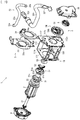
- FIG. 1 is a parts developed diagram illustrating a retractor according to the embodiment of the present invention.
- FIGs. 2(A) to 2(G) are cross-sectional views illustrating a tip reinforcing member in which Fig. 2(A) illustrates an embodiment illustrated in Fig. 1 , Fig. 2(B) illustrates a first modification, Fig. 2(C) illustrates a second modification, Fig. 2(D) illustrates a third modification, Fig. 2(E) illustrates a fourth modification, Fig. 2(F) illustrates a fifth modification, and Fig. 2(G) illustrates a sixth modification.
- a retractor 1 includes a spool 2 for winding a webbing that restrains an occupant, and a pretensioner 3 for winding the webbing and eliminating slack in an emergency.
- the pretensioner 3 includes a ring gear 31 on which the spool 2 is rotatably disposed, and power transmission units 32 for transmitting power to the ring gear 31 in an emergency.
- the power transmission units 32 includes a rod-shaped power transmission member 32a for transmitting power to the ring gear 31 while being plastically deformed, a tip reinforcing member 32b disposed on a tip side of the power transmission member 32a, a pipe 32c for containing the power transmission member 32a, and a gas generator 32d disposed at an end of the pipe 32c.
- the tip reinforcing member 32b has higher strength than the power transmission member 32a. It should be noted that an illustration of the webbing is omitted from Fig. 1 .
- the spool 2 is a retracting drum that retracts the webbing and is rotatably contained in a base frame 11 that forms a skeleton of the retractor 1.
- the base frame 11 includes, for example, a pair of opposed end surfaces 111 and 112, and a side surface 113 for connecting the end surfaces.
- the base frame 11 may include a tie plate 114 that is opposed to the side surface 113 and is connected to the end surfaces 111 and 112.
- a spring unit 4 is disposed on the end surface 111 side, and the pretensioner 3 and a lock mechanism 5 are disposed on the end surface 112 side. It should be noted that disposition of the spring unit 4, the pretensioner 3, the lock mechanism 5 or the like is not limited to that illustrated.
- the end surface 111 of the base frame 11 is formed with an opening 111a through which the spool 2 is inserted, and the end surface 112 of the base frame 11 is formed with an opening 112a that has internal teeth engageable with a pawl 52 of the lock mechanism 5. Furthermore, in an inside of the end surface 112 of the base frame 11, a part of the pretensioner 3 (e.g., the ring gear 31 or the like) is disposed. Furthermore, the lock mechanism 5 is disposed at an outside of the end surface 112 of the base frame 11, and the lock mechanism 5 is contained in a retainer cover 56.
- the retainer cover 56 may be disposed with a vehicle sensor 6 for detecting sudden deceleration or inclination of a vehicle body.
- the vehicle sensor 6 includes, for example, a spherical mass body and a sensor lever that is swung by a movement of the mass body.
- the vehicle sensor 6 may be fitted into an opening 112b formed on the end surface 112 of the base frame 11.
- the spool 2 includes a cavity in a central portion, through which a torsion bar 21 forming an axis is inserted. An end of the spool 2 is connected to an inside of a first end of the torsion bar 21, and a spring core of the spring unit 4 is connected to an outside of the first end of the torsion bar 21. Therefore, the spool 2 is connected to the spring unit 4 via the torsion bar 21, and is energized in a direction in which the webbing is wound by a power spring housed in the spring unit 4.
- a shaft portion may be formed on the end surface of the spool 2 such that the first end of the torsion bar 21 is connected to an inside of the shaft portion, and the spring unit 4 is connected to an outside of the shaft portion.
- units for applying a retracting force to the spool 2 is not limited to the spring unit 4, but may be other units using an electric motor or the like.
- a second end of the torsion bar 21 is connected to a locking base 51 of the lock mechanism 5.
- the locking base 51 is engageable with the base frame 11, and is capable of switching between a rotating state and a non-rotating state of the torsion bar 21. Therefore, even when subjected to a load in a direction of withdrawing the webbing in an operating state of the lock mechanism 5 (the state the locking base 51 is engaged with the base frame 11), a non-rotating state of the spool 2 can be maintained until a load equal to or more than a threshold value occurs in the torsion bar 21. Then, when the load equal to or more than the threshold value occurs in the torsion bar 21, the torsion bar 21 twists so that the spool 2 generates relative rotational movement to withdraw the webbing.
- the lock mechanism 5 includes the locking base 51 connected to an end of the torsion bar 21 and is capable of switching between a rotating state and a non-rotating state, the pawl 52 swingably disposed in the locking base 51, and a cover plate 53 for regulating a movement of the pawl 52 in an axial direction, a lock gear 54 disposed at an end of the torsion bar 21 so as to be adjacent to an outside of the locking base 51, a flywheel 55 swingably disposed to the lock gear 54, and the retainer cover 56 for containing these parts and rotatably supporting the locking base 51. It should be noted that the lock mechanism 5 is not limited to that with the structure illustrated, but those with various structures which conventionally exist may be optionally selected and used.
- the locking base 51 includes a circular disk part 51a, a ring gear supporting part 51b in substantially hexagonal cylindrical shape that is formed on the spool 2 side of the disk part 51a to support the ring gear 31, and a torsion bar supporting part 51c through which a second end of the torsion bar 21 is inserted. Additionally, the ring gear supporting part 51b is inserted with a bearing 22 that receives a shaft for a pretensioner cover 33 when the pretensioner 3 is actuated.
- a pinion connected to the spool 2 may be inserted through an inside of the ring gear 31 to engage internal teeth of the ring gear 31 with external teeth of the pinion as required thereby the rotation of the ring gear 31 is transmitted to the spool 2 via the pinion.
- the flywheel 55 swings and engages with internal teeth (not illustrated) of the retainer cover 56, and the rotation of the lock gear 54 is regulated. Additionally, when the vehicle sensor 6 is actuated, the sensor lever thereof engages with external teeth 54b of the lock gear 54, and rotation of the lock gear 54 is regulated.
- the lock mechanism 5 is not actuated, and the locking base 51 and the lock gear 54 are rotated together along with rotation of the spool 2.
- the pawl 52 is configured to maintain a state of being retracted to a position where the pawl 52 does not interfere with the internal teeth that are formed in the opening 112a of the base frame 112.
- the pretensioner 3 includes the ring gear 31, the power transmission units 32, the pretensioner cover 33 for housing the ring gear 31, and a guide spacer 34 for guiding a movement of the power transmission member 32a.
- the pretensioner cover 33 is disposed inside of the end surface 112 of the base frame 11, and the guide spacer 34 is contained in the pretensioner cover 33.
- the ring gear 31 is disposed so as to be positioned between the pretensioner cover 33 and the inside of the end surface 112 of the base frame 11.
- the ring gear 31 includes a plurality of engaging teeth 31a that are formed so as to protrude outward in a radial direction.
- the ring gear 31 is also referred to as a pinion gear.
- the power transmission units 32 includes the rod-shaped power transmission member 32a for transmitting power to the ring gear 31 while being plastically deformed, the tip reinforcing member 32b disposed on the tip side of the power transmission member 32a, the pipe 32c for containing the power transmission member 32a, the gas generator 32d disposed at the end of the pipe 32c, and a piston 32e disposed on a rear end side of the power transmission member 32a.
- the pipe 32c is disposed at a position where the tip faces the engaging teeth 31a of the ring gear 31 (between the pretensioner cover 33 and the inside of the end surface 112 of the base frame 11).
- the rear end side of the pipe 32c extends by a length required for the movement of the power transmission member 32a, and is formed so as to be curved along an outline of the retractor 1.
- the tip of the pipe 32c is formed with a cut 32f in a part of a periphery, and is structured such that the engaging teeth 31a of the ring gear 31 pass through in the pipe 32c from the cut 32f to be able to rotate.
- the gas generator 32d is disposed at the rear end of the pipe 32c, so that high pressure gas can be supplied into the pipe 32c.
- the gas generator 32d is, for example, a micro gas generator, and structured to inject gas into the pipe 32c in response to a detection signal from a vehicle body.
- the piston 32e is inserted between the gas generator 32d and the power transmission member 32a.
- the piston 32e has a function of forming a pressure-receiving part by filling a gap with the pipe 32c at the rear end portion of the power transmission member 32a, and pushing out the power transmission member 32a when the gas is supplied.
- the power transmission member 32a is, for example, a rod-shaped long slender part formed of a homopolymer of a POM resin, and is contained in the pipe 32c.
- the tip reinforcing member 32b has, for example, a cap shape that covers the tip of the tip reinforcing member 32b as illustrated in Fig. 2(A) , and the tip of the power transmission member 32a is fitted in a recess of the tip reinforcing member 32b.
- the tip reinforcing member 32b has higher strength than at least the power transmission member 32a.
- the "strength" here is intended to include indicators such as tensile strength, yield strength, bending strength, hardness, ductility, and toughness. Therefore, for example, the tip reinforcing member 32b only has to be formed harder than a resin that forms the power transmission member 32a, which may be made of metal such as aluminum or iron, or may be made of a resin. Additionally, the tip reinforcing member 32b is formed such that a length L of a peripheral surface with respect to an axial direction of the power transmission member 32a (the direction indicated by dotted-chain lines in the figure) is smaller than a pitch P (see Fig. 3(A) ) of the ring gear 31.
- the power transmission units 32 that includes such the tip reinforcing member 32b is maintained in a state in which the power transmission member 32a and the tip reinforcing member 32b are contained in the pipe 32c at the normal time (when the pretensioner 3 is not actuated). Then, in an emergency such as a vehicle collision (when the pretensioner 3 is actuated), the power transmission member 32a and the tip reinforcing member 32b are pushed out in the pipe 32c by the gas supplied by the gas generator 32d, and are released outside from the tip of the pipe 32c as illustrated in Fig. 3(A) .
- the tip reinforcing member 32b Since the tip reinforcing member 32b is disposed at the tip of the power transmission member 32a, the tip reinforcing member 32b firstly contacts with the engaging teeth 31a of the ring gear 31 when pushed out from the tip of the pipe 32c. Since the tip reinforcing member 32b has higher strength than the power transmission member 32a, the tip of the power transmission member 32a can endure an impact of collision with the engaging teeth 31a of the ring gear 31. Additionally, in order to prevent the tip reinforcing member 32b from being broken, the tip reinforcing member 32b may have higher strength than the engaging teeth 31a of the ring gear 31.
- the tip reinforcing member 32b has a relationship of the length L in the axial direction ⁇ the pitch P, the tip reinforcing member 32b does not obstruct rotation of the ring gear 31. Therefore, contact of the tip reinforcing member 32b with the engaging teeth 31a starts rotation of the ring gear 31, and the power transmission member 32a is to be engaged with the engaging teeth 31a, from one of the engaging teeth 31a that is subsequent to one of the engaging teeth 31a that is in contact with the tip reinforcing member 32b.
- the power transmission member 32a moves along a side wall 33a of the pretensioner cover 33 while being plastically deformed by engaging with engaging teeth 31a, and eventually reaches and stops at a stopper 34a formed in the guide spacer 34 as illustrated in Fig. 3(B) .
- the tip reinforcing member 32b with higher strength than the power transmission member 32a on the tip side of the rod-shaped power transmission member 32a.
- a portion with higher strength than the power transmission member 32a can firstly collide with the ring gear 31 and prevent the power transmission member 32a from being chipped or broken.
- a material or a manufacturing method may be selected in consideration of slidability and an engaging property. Therefore, strength and slidability of the rod-shaped power transmission member 32a may both be achieved.
- a first modification illustrated in Fig. 2(B) is made by forming a projection 321 with a small diameter at the tip of the power transmission member 32a, and fitting a cap-shaped tip reinforcing member 32b to the projection 321.
- an outer diameter of the tip reinforcing member 32b and an outer diameter of the main body part of the power transmission member 32a may have substantially the same size.
- a second modification illustrated in Fig. 2(C) is made by forming a projection 321 with a small diameter at a tip of the power transmission member 32a, and fitting a cylindrical-shaped tip reinforcing member 32b to the projection 321.
- an outer diameter of the tip reinforcing member 32b and an outer diameter of the main body part of the power transmission member 32a may have substantially the same size.
- a third modification illustrated in Fig. 2 (D) is made by forming a recess 322 with a small diameter at a tip of the power transmission member 32a, and fitting a shaft portion of a cross-sectional T-shaped tip reinforcing member 32b in the recess 322.
- an outer diameter of the tip reinforcing member 32b and an outer diameter of the main body part of the power transmission member 32a may have substantially the same size.
- a fourth modification illustrated in Fig. 2(E) is made by disposing a cylindrical-shaped tip reinforcing member 32b with substantially the same outer diameter at a tip of the power transmission member 32a.
- the tip reinforcing member 32b may be fixed to a tip end surface of the power transmission member 32a with an adhesive or the like, or may be disposed at a position adjacent to the tip end surface of the power transmission member 32a by pressing into the pipe 32c. In this case, the tip reinforcing member 32b may be disposed at a position apart from the tip of the power transmission member 32a.
- the tip reinforcing member 32b be positioned at the tip of the power transmission member 32a, and that the tip reinforcing member 32b be structured so as to firstly contact with the ring gear 31 when the tip of the power transmission member 32a is released from the pipe 32c.
- a fifth modification illustrated in Fig. 2(F) is made by embedding a substantially cylindrical-shaped tip reinforcing member 32b at the tip of the power transmission member 32a.
- the tip reinforcing member 32b is, for example, formed of metal, reinforced fiber, or the like, and molded with a resin.
- a sixth modification illustrated in Fig. 2 (G) is made by molding the tip of the power transmission member 32a with a hard resin.
- the tip reinforcing member 32b is formed, for example, by two-color molding using a resin that forms the power transmission member 32a, and a resin with higher strength than the resin that forms the power transmission member 32a.
- the tip reinforcing member 32b may be fixed to the power transmission member 32a, may be pressed into the pipe 32c, may be molded in the power transmission member 32a, or may be made by hardening a part of the power transmission member 32a.
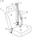
- Fig. 4 is an overall structure diagram illustrating the seat belt device according to the embodiment of the present invention. It should be noted that, for convenience of description, parts other than the seat belt device are indicated by dotted-chain lines in Fig. 4 .
- a seat belt device 100 includes a webbing W for restraining an occupant, a retractor 1 for retracting the webbing W, a guide anchor 101 that is disposed on a vehicle body side and guides the webbing W, a belt anchor 102 for fixing the webbing W to the vehicle body side, a buckle 103 that is disposed on a side surface of a seat S, and a tongue 104 that is disposed in the webbing W.
- the retractor 1 has the structure illustrated in Fig. 1 .
- the seat S includes, for example, a seat portion S1 on which the occupant sits, a backrest portion S2 that is positioned back of the occupant, and a headrest portion S3 for supporting the head of the occupant.
- the retractor 1 is disposed, for example, in a B-pillar P of the vehicle body.
- the buckle 103 is often disposed on a side surface of the seat portion S1
- the belt anchor 102 is often disposed on a lower surface of the seat portion S1.
- the guide anchor 101 is often disposed at the B-pillar P. Then, a first end of the webbing W is connected to the belt anchor 102, and a second end of the webbing W is connected to the retractor 1 via the guide anchor 101.
- the webbing W is withdrawn from the retractor 1 while being slid through an insertion hole of the guide anchor 101. Furthermore, when the occupant fastens the seat belt or releases the seat belt to leave the vehicle, the webbing W is retracted due to operation of the spring unit 4 of the retractor 1 until a certain amount of load is applied to the webbing W.
- the above-described seat belt device 100 is made by applying the above-described retractor 1 according to the above-described embodiment to a typical seat belt device for a front seat.
- the seat belt device 100 of the embodiment there is disposed the tip reinforcing member 32b with higher strength than the power transmission member 32a on the tip side of the rod-shaped power transmission member 32a.
- a portion with higher strength than the power transmission member 32a can firstly collides with the ring gear 31 to prevent the power transmission member 32a from being chipped or broken.
- the seat belt device 100 is not limited to the use for a front seat, but it may be easily applied to, for example, a rear seat with the guide anchor 101 omitted.
- the present invention is not limited to the above-described embodiment.
- the present invention can be changed in various manners without departing from the gist of the present invention.
- the present invention may be applied to a seat belt device used for a conveyance other than the vehicle.
Landscapes
- Engineering & Computer Science (AREA)
- Mechanical Engineering (AREA)
- Automotive Seat Belt Assembly (AREA)
Abstract
Description
- The present invention relates to a pretensioner, a retractor, and a seat belt device, and in particular, relates to a pretensioner, a retractor, and a seat belt device that are suitable for structures having a rod-shaped power transmission member.
- Vehicles such as automobiles generally are provided with seat belt devices for restraining an occupant in a seat that includes a seat portion on which the occupant sits and a backrest portion positioned back of the occupant. Such a seat belt device includes a webbing for restraining the occupant, a retractor for retracting the webbing, a guide anchor that is disposed on a vehicle body side and guides the webbing, a belt anchor for fixing the webbing to the vehicle body side, a buckle disposed on a side surface of the seat, and a tongue disposed on the webbing. The tongue is fitted into the buckle to restrain the occupant in the seat with the webbing. In such the seat belt device, a first end of the webbing is fixed to the belt anchor, and a second end of the webbing is inserted into the guide anchor to be connected to the retractor.
- It is becoming common that such the retractor has a pretensioner that eliminates slack in the webbing in an emergency such as a vehicle collision (e.g., refer to
Patent Literatures 1 and 2). Pretensioners described inPatent Literatures Patent Literature 1 is a plurality of mass bodies (balls), and the load transmission element described inPatent Literature 2 is a long slender rod member made of a resin. -
- Patent Literature 1:
JP 2007-522030 W - Patent Literature 2:
WO 2012/143090 A - In the pretensioner described in
Patent Literature 1 described above, since the load transmission element is a plurality of mass bodies, the mass bodies must be supplied to the pinion gear at appropriate timing, otherwise the mass bodies get engaged with the pinion gear to prevent rotation of the pinion gear. Therefore, the pretensioner with such the structure requires various measures. - In contrast, in the pretensioner described in
Patent Literature 2, the load transmission element is the rod member made of a resin, and the rod member is plastically deformed to rotate the pinion gear. This eliminates the need for consideration of timing for supplying the rod member to the pinion gear, simplifies a structure, and reduces the number of parts. - For the pretensioner using such the rod member made of a resin, the rod member needs to be engaged with the pinion gear in an initial stage of driving the pinion gear. In this case, since a load is the highest when the rod member firstly collides with the pinion gear, strength that can prevent a tip of the rod member from being chipped or broken must be considered when selecting a material of the rod member. On the other hands, if entire strength of the rod member is increased, it must also be simultaneously considered that this may affect a function that enables the rod member to efficiently slides within a curved pipe.
- The present invention is made in view of the above-described problems, and an object of the present invention is to provide a pretensioner, a retractor, and a seat belt device in which strength and slidability of a rod-shaped power transmission member may both be achieved.
- According to the present invention, there is provided a pretensioner including a ring gear to which the spool for winding a webbing that restrains an occupant is rotatably disposed, and power transmission units for transmitting power to the ring gear in an emergency, wherein the power transmission units includes a rod-shaped power transmission member for transmitting power to the ring gear while being plastically deformed, a tip reinforcing member disposed on a tip side of the power transmission member, a pipe for containing the power transmission member, and a gas generator disposed at an end of the pipe. The tip reinforcing member has higher strength than the power transmission member.
- Additionally, according to the present invention, there is provided a retractor including a spool for winding a webbing that restrains an occupant, and a pretensioner for winding the webbing and eliminating slack in an emergency, wherein the pretensioner includes a ring gear to which the spool is rotatably disposed, and power transmission units for transmitting power to the ring gear in an emergency. The power transmission units includes a rod-shaped power transmission member for transmitting power to the ring gear while being plastically deformed, a tip reinforcing member disposed on a tip side of the power transmission member, a pipe for containing the power transmission member, and a gas generator disposed at an end of the pipe. The tip reinforcing member has higher strength than the power transmission member.
- Furthermore, according to the present invention, there is provided a seat belt device including a webbing for restraining an occupant, a retractor for winding the webbing, a belt anchor for fixing the webbing on a vehicle body side, a buckle disposed on a side surface of the seat, and a tongue disposed in the webbing, wherein the retractor includes a spool for winding the webbing that restrains the occupant, and a pretensioner for winding the webbing and eliminating slack in an emergency. The pretensioner includes a ring gear to which the spool is rotatably disposed, and power transmission units for transmitting power to the ring gear --in an emergency. The power transmission units includes a rod-shaped power transmission member for transmitting power to the ring gear while being plastically deformed, a tip reinforcing member disposed on a tip side of the power transmission member, a pipe for containing the power transmission member, and a gas generator disposed at an end of the pipe. The tip reinforcing member has higher strength than the power transmission member.
- In the above-described pretensioner, the retractor, and the seat belt device, the tip reinforcing member may be formed such that a length with respect to an axial direction of the power transmission member is smaller than a pitch of the ring gear. Moreover, the tip reinforcing member may be fixed to the power transmission member, may be pressed into the pipe, may be molded in the power transmission member, or may be made by hardening a part of the power transmission member. Furthermore, the tip reinforcing member may have higher strength than the ring gear.
- According to the above-described pretensioner, the retractor, and the seat belt device of the present invention, there is disposed the tip reinforcing member with higher strength than the power transmission member on the tip side of the rod-shaped power transmission member. Thereby, in an initial stage of driving the ring gear, a portion with higher strength than the power transmission member can firstly collides with the ring gear to prevent the power transmission member from being chipped or broken. Additionally, for the rod part of the power transmission member, a material or a manufacturing method may be selected in consideration of slidability and an engaging property. Therefore, strength and slidability of a rod-shaped power transmission member may both be achieved.
-
-
Fig. 1 is a parts developed diagram illustrating a retractor according to an embodiment of the present invention. -
Figs. 2(A) to 2(G) are cross-sectional views illustrating a tip reinforcing member in whichFig. 2(A) illustrates an embodiment illustrated inFig. 1 ,Fig. 2(B) illustrates a first modification,Fig. 2(C) illustrates a second modification,Fig. 2(D) illustrates a third modification,Fig. 2(E) illustrates a fourth modification,Fig. 2(F) illustrates a fifth modification, andFig. 2(G) illustrates a sixth modification. -
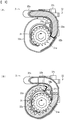
Figs. 3(A) and 3(B) are partial cross-sectional views of a pretensioner illustrating an operation of the present invention in whichFig. 3(A) illustrates an initial stage of driving a ring gear, andFig. 3(B) illustrates a completion state of driving the ring gear. -
Fig. 4 is an overall structure diagram illustrating a seat belt device according to the embodiment of the present invention. - An embodiment of the present invention is described below with reference to
Figs. 1 to 4 . Here,Fig. 1 is a parts developed diagram illustrating a retractor according to the embodiment of the present invention.Figs. 2(A) to 2(G) are cross-sectional views illustrating a tip reinforcing member in whichFig. 2(A) illustrates an embodiment illustrated inFig. 1 ,Fig. 2(B) illustrates a first modification,Fig. 2(C) illustrates a second modification,Fig. 2(D) illustrates a third modification,Fig. 2(E) illustrates a fourth modification,Fig. 2(F) illustrates a fifth modification, andFig. 2(G) illustrates a sixth modification. - As illustrated in
Fig. 1 , aretractor 1 according to the embodiment of the present invention includes aspool 2 for winding a webbing that restrains an occupant, and apretensioner 3 for winding the webbing and eliminating slack in an emergency. Thepretensioner 3 includes aring gear 31 on which thespool 2 is rotatably disposed, andpower transmission units 32 for transmitting power to thering gear 31 in an emergency. Thepower transmission units 32 includes a rod-shapedpower transmission member 32a for transmitting power to thering gear 31 while being plastically deformed, atip reinforcing member 32b disposed on a tip side of thepower transmission member 32a, apipe 32c for containing thepower transmission member 32a, and agas generator 32d disposed at an end of thepipe 32c. Thetip reinforcing member 32b has higher strength than thepower transmission member 32a. It should be noted that an illustration of the webbing is omitted fromFig. 1 . - The
spool 2 is a retracting drum that retracts the webbing and is rotatably contained in abase frame 11 that forms a skeleton of theretractor 1. Thebase frame 11 includes, for example, a pair ofopposed end surfaces side surface 113 for connecting the end surfaces. Thebase frame 11 may include atie plate 114 that is opposed to theside surface 113 and is connected to theend surfaces spring unit 4 is disposed on theend surface 111 side, and thepretensioner 3 and alock mechanism 5 are disposed on theend surface 112 side. It should be noted that disposition of thespring unit 4, thepretensioner 3, thelock mechanism 5 or the like is not limited to that illustrated. - Furthermore, the
end surface 111 of thebase frame 11 is formed with anopening 111a through which thespool 2 is inserted, and theend surface 112 of thebase frame 11 is formed with anopening 112a that has internal teeth engageable with apawl 52 of thelock mechanism 5. Furthermore, in an inside of theend surface 112 of thebase frame 11, a part of the pretensioner 3 (e.g., thering gear 31 or the like) is disposed. Furthermore, thelock mechanism 5 is disposed at an outside of theend surface 112 of thebase frame 11, and thelock mechanism 5 is contained in aretainer cover 56. - The
retainer cover 56 may be disposed with a vehicle sensor 6 for detecting sudden deceleration or inclination of a vehicle body. The vehicle sensor 6 includes, for example, a spherical mass body and a sensor lever that is swung by a movement of the mass body. The vehicle sensor 6 may be fitted into an opening 112b formed on theend surface 112 of thebase frame 11. - The
spool 2 includes a cavity in a central portion, through which atorsion bar 21 forming an axis is inserted. An end of thespool 2 is connected to an inside of a first end of thetorsion bar 21, and a spring core of thespring unit 4 is connected to an outside of the first end of thetorsion bar 21. Therefore, thespool 2 is connected to thespring unit 4 via thetorsion bar 21, and is energized in a direction in which the webbing is wound by a power spring housed in thespring unit 4. Although not illustrated, a shaft portion may be formed on the end surface of thespool 2 such that the first end of thetorsion bar 21 is connected to an inside of the shaft portion, and thespring unit 4 is connected to an outside of the shaft portion. Furthermore, units for applying a retracting force to thespool 2 is not limited to thespring unit 4, but may be other units using an electric motor or the like. - Additionally, a second end of the
torsion bar 21 is connected to alocking base 51 of thelock mechanism 5. As explained below, the lockingbase 51 is engageable with thebase frame 11, and is capable of switching between a rotating state and a non-rotating state of thetorsion bar 21. Therefore, even when subjected to a load in a direction of withdrawing the webbing in an operating state of the lock mechanism 5 (the state the lockingbase 51 is engaged with the base frame 11), a non-rotating state of thespool 2 can be maintained until a load equal to or more than a threshold value occurs in thetorsion bar 21. Then, when the load equal to or more than the threshold value occurs in thetorsion bar 21, thetorsion bar 21 twists so that thespool 2 generates relative rotational movement to withdraw the webbing. - The
lock mechanism 5 includes the lockingbase 51 connected to an end of thetorsion bar 21 and is capable of switching between a rotating state and a non-rotating state, thepawl 52 swingably disposed in the lockingbase 51, and acover plate 53 for regulating a movement of thepawl 52 in an axial direction, alock gear 54 disposed at an end of thetorsion bar 21 so as to be adjacent to an outside of the lockingbase 51, aflywheel 55 swingably disposed to thelock gear 54, and theretainer cover 56 for containing these parts and rotatably supporting the lockingbase 51. It should be noted that thelock mechanism 5 is not limited to that with the structure illustrated, but those with various structures which conventionally exist may be optionally selected and used. - The locking
base 51 includes acircular disk part 51a, a ringgear supporting part 51b in substantially hexagonal cylindrical shape that is formed on thespool 2 side of thedisk part 51a to support thering gear 31, and a torsionbar supporting part 51c through which a second end of thetorsion bar 21 is inserted. Additionally, the ringgear supporting part 51b is inserted with abearing 22 that receives a shaft for apretensioner cover 33 when thepretensioner 3 is actuated. - Although an example has been described where the
ring gear 31 is fixed to the lockingbase 51 here, it is not limited to this structure. For example, a pinion connected to thespool 2 may be inserted through an inside of thering gear 31 to engage internal teeth of thering gear 31 with external teeth of the pinion as required thereby the rotation of thering gear 31 is transmitted to thespool 2 via the pinion. - According to the
lock mechanism 5 with the structure described above, when the webbing is faster than a normal speed of withdrawal, that is, a withdrawing force of the webbing exceeds a specified threshold value, theflywheel 55 swings and engages with internal teeth (not illustrated) of theretainer cover 56, and the rotation of thelock gear 54 is regulated. Additionally, when the vehicle sensor 6 is actuated, the sensor lever thereof engages withexternal teeth 54b of thelock gear 54, and rotation of thelock gear 54 is regulated. - When the rotation of the
lock gear 54 is regulated, the lockingbase 51 and thelock gear 54 are rotated relative to each other, and thepawl 52 swings along with this relative rotation to engage a tip of thepawl 52 with the internal teeth that are formed in theopening 112a of thebase frame 112. As a result, rotation of the lockingbase 51 is regulated, and rotation of thespool 2 is also regulated. Thus, the withdrawal of the webbing is locked. - It should be noted that, at normal time (when the withdrawing force of the webbing is equal to or less than a specified threshold value), the
lock mechanism 5 is not actuated, and the lockingbase 51 and thelock gear 54 are rotated together along with rotation of thespool 2. Thus, since the lockingbase 51 and thelock gear 54 are not rotated relative to each other at the normal time, thepawl 52 is configured to maintain a state of being retracted to a position where thepawl 52 does not interfere with the internal teeth that are formed in theopening 112a of thebase frame 112. - The
pretensioner 3 includes thering gear 31, thepower transmission units 32, thepretensioner cover 33 for housing thering gear 31, and aguide spacer 34 for guiding a movement of thepower transmission member 32a. Thepretensioner cover 33 is disposed inside of theend surface 112 of thebase frame 11, and theguide spacer 34 is contained in thepretensioner cover 33. Additionally, thering gear 31 is disposed so as to be positioned between thepretensioner cover 33 and the inside of theend surface 112 of thebase frame 11. Thering gear 31 includes a plurality of engagingteeth 31a that are formed so as to protrude outward in a radial direction. Thering gear 31 is also referred to as a pinion gear. - The
power transmission units 32 includes the rod-shapedpower transmission member 32a for transmitting power to thering gear 31 while being plastically deformed, thetip reinforcing member 32b disposed on the tip side of thepower transmission member 32a, thepipe 32c for containing thepower transmission member 32a, thegas generator 32d disposed at the end of thepipe 32c, and apiston 32e disposed on a rear end side of thepower transmission member 32a. - The
pipe 32c is disposed at a position where the tip faces the engagingteeth 31a of the ring gear 31 (between thepretensioner cover 33 and the inside of theend surface 112 of the base frame 11). The rear end side of thepipe 32c extends by a length required for the movement of thepower transmission member 32a, and is formed so as to be curved along an outline of theretractor 1. As illustrated inFig. 1 , the tip of thepipe 32c is formed with acut 32f in a part of a periphery, and is structured such that the engagingteeth 31a of thering gear 31 pass through in thepipe 32c from thecut 32f to be able to rotate. - Additionally, the
gas generator 32d is disposed at the rear end of thepipe 32c, so that high pressure gas can be supplied into thepipe 32c. Thegas generator 32d is, for example, a micro gas generator, and structured to inject gas into thepipe 32c in response to a detection signal from a vehicle body. Additionally, thepiston 32e is inserted between thegas generator 32d and thepower transmission member 32a. Thepiston 32e has a function of forming a pressure-receiving part by filling a gap with thepipe 32c at the rear end portion of thepower transmission member 32a, and pushing out thepower transmission member 32a when the gas is supplied. - The
power transmission member 32a is, for example, a rod-shaped long slender part formed of a homopolymer of a POM resin, and is contained in thepipe 32c. Thetip reinforcing member 32b has, for example, a cap shape that covers the tip of thetip reinforcing member 32b as illustrated inFig. 2(A) , and the tip of thepower transmission member 32a is fitted in a recess of thetip reinforcing member 32b. - Additionally, the
tip reinforcing member 32b has higher strength than at least thepower transmission member 32a. The "strength" here is intended to include indicators such as tensile strength, yield strength, bending strength, hardness, ductility, and toughness. Therefore, for example, thetip reinforcing member 32b only has to be formed harder than a resin that forms thepower transmission member 32a, which may be made of metal such as aluminum or iron, or may be made of a resin. Additionally, thetip reinforcing member 32b is formed such that a length L of a peripheral surface with respect to an axial direction of thepower transmission member 32a (the direction indicated by dotted-chain lines in the figure) is smaller than a pitch P (seeFig. 3(A) ) of thering gear 31. - The
power transmission units 32 that includes such thetip reinforcing member 32b is maintained in a state in which thepower transmission member 32a and thetip reinforcing member 32b are contained in thepipe 32c at the normal time (when thepretensioner 3 is not actuated). Then, in an emergency such as a vehicle collision (when thepretensioner 3 is actuated), thepower transmission member 32a and thetip reinforcing member 32b are pushed out in thepipe 32c by the gas supplied by thegas generator 32d, and are released outside from the tip of thepipe 32c as illustrated inFig. 3(A) . - Since the
tip reinforcing member 32b is disposed at the tip of thepower transmission member 32a, thetip reinforcing member 32b firstly contacts with the engagingteeth 31a of thering gear 31 when pushed out from the tip of thepipe 32c. Since thetip reinforcing member 32b has higher strength than thepower transmission member 32a, the tip of thepower transmission member 32a can endure an impact of collision with the engagingteeth 31a of thering gear 31. Additionally, in order to prevent thetip reinforcing member 32b from being broken, thetip reinforcing member 32b may have higher strength than the engagingteeth 31a of thering gear 31. - Furthermore, since the
tip reinforcing member 32b has a relationship of the length L in the axial direction < the pitch P, thetip reinforcing member 32b does not obstruct rotation of thering gear 31. Therefore, contact of thetip reinforcing member 32b with the engagingteeth 31a starts rotation of thering gear 31, and thepower transmission member 32a is to be engaged with the engagingteeth 31a, from one of the engagingteeth 31a that is subsequent to one of the engagingteeth 31a that is in contact with thetip reinforcing member 32b. Thepower transmission member 32a moves along aside wall 33a of thepretensioner cover 33 while being plastically deformed by engaging with engagingteeth 31a, and eventually reaches and stops at astopper 34a formed in theguide spacer 34 as illustrated inFig. 3(B) . - According to the above-described
pretensioner 3 and theretractor 1 of the embodiment, there is disposed thetip reinforcing member 32b with higher strength than thepower transmission member 32a on the tip side of the rod-shapedpower transmission member 32a. Thereby, in the initial stage of driving thering gear 31, a portion with higher strength than thepower transmission member 32a can firstly collide with thering gear 31 and prevent thepower transmission member 32a from being chipped or broken. Additionally, for thepower transmission member 32a, a material or a manufacturing method may be selected in consideration of slidability and an engaging property. Therefore, strength and slidability of the rod-shapedpower transmission member 32a may both be achieved. - Next, modifications of the
tip reinforcing member 32b are described with reference toFigs. 2(B) to 2(G) . A first modification illustrated inFig. 2(B) is made by forming aprojection 321 with a small diameter at the tip of thepower transmission member 32a, and fitting a cap-shapedtip reinforcing member 32b to theprojection 321. In this case, an outer diameter of thetip reinforcing member 32b and an outer diameter of the main body part of thepower transmission member 32a may have substantially the same size. - A second modification illustrated in
Fig. 2(C) is made by forming aprojection 321 with a small diameter at a tip of thepower transmission member 32a, and fitting a cylindrical-shapedtip reinforcing member 32b to theprojection 321. In this case, an outer diameter of thetip reinforcing member 32b and an outer diameter of the main body part of thepower transmission member 32a may have substantially the same size. - A third modification illustrated in
Fig. 2 (D) is made by forming arecess 322 with a small diameter at a tip of thepower transmission member 32a, and fitting a shaft portion of a cross-sectional T-shapedtip reinforcing member 32b in therecess 322. In this case, an outer diameter of thetip reinforcing member 32b and an outer diameter of the main body part of thepower transmission member 32a may have substantially the same size. - A fourth modification illustrated in
Fig. 2(E) is made by disposing a cylindrical-shapedtip reinforcing member 32b with substantially the same outer diameter at a tip of thepower transmission member 32a. Thetip reinforcing member 32b may be fixed to a tip end surface of thepower transmission member 32a with an adhesive or the like, or may be disposed at a position adjacent to the tip end surface of thepower transmission member 32a by pressing into thepipe 32c. In this case, thetip reinforcing member 32b may be disposed at a position apart from the tip of thepower transmission member 32a. In the other words, it is sufficient that thetip reinforcing member 32b be positioned at the tip of thepower transmission member 32a, and that thetip reinforcing member 32b be structured so as to firstly contact with thering gear 31 when the tip of thepower transmission member 32a is released from thepipe 32c. - A fifth modification illustrated in
Fig. 2(F) is made by embedding a substantially cylindrical-shapedtip reinforcing member 32b at the tip of thepower transmission member 32a. Thetip reinforcing member 32b is, for example, formed of metal, reinforced fiber, or the like, and molded with a resin. - A sixth modification illustrated in
Fig. 2 (G) is made by molding the tip of thepower transmission member 32a with a hard resin. Thetip reinforcing member 32b is formed, for example, by two-color molding using a resin that forms thepower transmission member 32a, and a resin with higher strength than the resin that forms thepower transmission member 32a. - As described above, if the
tip reinforcing member 32b is positioned at the tip of thepower transmission member 32a and is structured so as to be able to firstly collide when contacting thering gear 31, thetip reinforcing member 32b may be fixed to thepower transmission member 32a, may be pressed into thepipe 32c, may be molded in thepower transmission member 32a, or may be made by hardening a part of thepower transmission member 32a. - Next, a seat belt device according to the embodiment of the present invention is described below with reference to
Fig. 4 . Here,Fig. 4 is an overall structure diagram illustrating the seat belt device according to the embodiment of the present invention. It should be noted that, for convenience of description, parts other than the seat belt device are indicated by dotted-chain lines inFig. 4 . - A
seat belt device 100 according to the embodiment illustrated inFig. 4 includes a webbing W for restraining an occupant, aretractor 1 for retracting the webbing W, aguide anchor 101 that is disposed on a vehicle body side and guides the webbing W, abelt anchor 102 for fixing the webbing W to the vehicle body side, abuckle 103 that is disposed on a side surface of a seat S, and atongue 104 that is disposed in the webbing W. Theretractor 1 has the structure illustrated inFig. 1 . - Components other than the
retractor 1 are briefly described below. The seat S includes, for example, a seat portion S1 on which the occupant sits, a backrest portion S2 that is positioned back of the occupant, and a headrest portion S3 for supporting the head of the occupant. Theretractor 1 is disposed, for example, in a B-pillar P of the vehicle body. In general, thebuckle 103 is often disposed on a side surface of the seat portion S1, and thebelt anchor 102 is often disposed on a lower surface of the seat portion S1. Furthermore, theguide anchor 101 is often disposed at the B-pillar P. Then, a first end of the webbing W is connected to thebelt anchor 102, and a second end of the webbing W is connected to theretractor 1 via theguide anchor 101. - Accordingly, in order to fit the
tongue 104 into thebuckle 103, the webbing W is withdrawn from theretractor 1 while being slid through an insertion hole of theguide anchor 101. Furthermore, when the occupant fastens the seat belt or releases the seat belt to leave the vehicle, the webbing W is retracted due to operation of thespring unit 4 of theretractor 1 until a certain amount of load is applied to the webbing W. - The above-described
seat belt device 100 is made by applying the above-describedretractor 1 according to the above-described embodiment to a typical seat belt device for a front seat. According to theseat belt device 100 of the embodiment, there is disposed thetip reinforcing member 32b with higher strength than thepower transmission member 32a on the tip side of the rod-shapedpower transmission member 32a. Thereby, in the initial stage of driving thering gear 31, a portion with higher strength than thepower transmission member 32a can firstly collides with thering gear 31 to prevent thepower transmission member 32a from being chipped or broken. It should be noted that theseat belt device 100 is not limited to the use for a front seat, but it may be easily applied to, for example, a rear seat with theguide anchor 101 omitted. - The present invention is not limited to the above-described embodiment. Of course, the present invention can be changed in various manners without departing from the gist of the present invention. For example, the present invention may be applied to a seat belt device used for a conveyance other than the vehicle.
-
- 1
- retractor
- 2
- spool
- 3
- pretensioner
- 4
- spring unit
- 5
- lock mechanism
- 6
- vehicle sensor
- 11
- base frame
- 21
- torsion bar
- 22
- bearing
- 31
- ring gear
- 31a
- engaging teeth
- 32
- power transmission units
- 32a
- power transmission member
- 32b
- tip reinforcing member
- 32c
- pipe
- 32d
- gas generator
- 32e
- piston
- 32f
- cut
- 33
- pretensioner cover
- 33a
- side wall
- 34
- guide spacer
- 34a
- stopper
- 51
- locking base
- 51a
- disk part
- 51b
- ring gear supporting part
- 51c
- torsion bar supporting part
- 52
- pawl
- 53
- cover plate
- 54
- lock gear
- 54a
- internal teeth
- 54b
- external teeth
- 55
- flywheel
- 56
- retainer cover
- 100
- seat belt device
- 101
- guide anchor
- 102
- belt anchor
- 103
- buckle
- 104
- tongue
- 111, 112
- end surface
- 111a
- opening
- 112a, 112b
- opening
- 113
- side surface
- 114
- tie plate
- 321
- projection
- 322
- recess
Claims (6)
- A pretensioner comprising:a ring gear to which a spool is rotatably disposed, the spool winding a webbing for restraining an occupant; andpower transmission units for transmitting power to the ring gear in an emergency, whereinthe power transmission units comprises a rod-shaped power transmission member for transmitting power to the ring gear while being plastically deformed, a tip reinforcing member disposed on a tip side of the power transmission member, a pipe for containing the power transmission member, and a gas generator disposed at an end of the pipe, andthe tip reinforcing member has higher strength than the power transmission member.
- The pretensioner according to claim 1, wherein the tip reinforcing member is formed such that a length with respect to an axial direction of the power transmission member is smaller than a pitch of the ring gear.
- The pretensioner according to claim 1, wherein the tip reinforcing member is fixed to the power transmission member, pressed into the pipe, molded in the power transmission member, or made by hardening a part of the power transmission member.
- The pretensioner according to claim 1, wherein the tip reinforcing member has higher strength than the ring gear.
- A retractor comprising:a spool for winding a webbing that restrains an occupant; anda pretensioner for winding the webbing and eliminating slack in an emergency, whereinthe pretensioner is a pretensioner according to any one of claims 1 to 4.
- A seat belt device comprising:a webbing for restraining an occupant;a retractor for winding the webbing;a belt anchor for fixing the webbing on a vehicle body side;a buckle disposed on a side surface of the seat; anda tongue disposed in the webbing, whereinthe retractor includes a pretensioner according to any one of claims 1 to 4.
Applications Claiming Priority (2)
| Application Number | Priority Date | Filing Date | Title |
|---|---|---|---|
| JP2014161957A JP6389394B2 (en) | 2014-08-07 | 2014-08-07 | Pretensioner, retractor and seat belt device |
| PCT/JP2015/071069 WO2016021422A1 (en) | 2014-08-07 | 2015-07-24 | Pretensioner, retractor, and seat belt device |
Publications (3)
| Publication Number | Publication Date |
|---|---|
| EP3187382A1 true EP3187382A1 (en) | 2017-07-05 |
| EP3187382A4 EP3187382A4 (en) | 2018-04-04 |
| EP3187382B1 EP3187382B1 (en) | 2019-06-26 |
Family
ID=55263694
Family Applications (1)
| Application Number | Title | Priority Date | Filing Date |
|---|---|---|---|
| EP15829796.0A Not-in-force EP3187382B1 (en) | 2014-08-07 | 2015-07-24 | Pretensioner, retractor, and seat belt device |
Country Status (4)
| Country | Link |
|---|---|
| US (1) | US10308214B2 (en) |
| EP (1) | EP3187382B1 (en) |
| JP (1) | JP6389394B2 (en) |
| WO (1) | WO2016021422A1 (en) |
Cited By (2)
| Publication number | Priority date | Publication date | Assignee | Title |
|---|---|---|---|---|
| US10525932B2 (en) | 2016-09-07 | 2020-01-07 | Joyson Safety Systems Japan K.K. | Pretensioner, retractor and seat belt device |
| DE102020204091A1 (en) | 2020-03-30 | 2021-09-30 | Joyson Safety Systems Germany Gmbh | Belt retractor with tensioner drive |
Families Citing this family (24)
| Publication number | Priority date | Publication date | Assignee | Title |
|---|---|---|---|---|
| GB201413898D0 (en) * | 2014-08-06 | 2014-09-17 | Moog Controls Ltd | Firing mechanism |
| JP6694766B2 (en) * | 2016-06-09 | 2020-05-20 | 株式会社東海理化電機製作所 | Webbing take-up device |
| JP6702805B2 (en) * | 2016-06-09 | 2020-06-03 | 株式会社東海理化電機製作所 | Webbing take-up device |
| JP6764698B2 (en) * | 2016-06-09 | 2020-10-07 | 株式会社東海理化電機製作所 | Webbing winder |
| JP6752630B2 (en) * | 2016-06-09 | 2020-09-09 | 株式会社東海理化電機製作所 | Webbing winder |
| JP6649848B2 (en) * | 2016-06-09 | 2020-02-19 | 株式会社東海理化電機製作所 | Webbing take-up device |
| JP6620069B2 (en) * | 2016-06-09 | 2019-12-11 | 株式会社東海理化電機製作所 | Webbing take-up device |
| DE102016118464B4 (en) * | 2016-09-29 | 2025-08-07 | Zf Automotive Germany Gmbh | Belt tensioners |
| US10259426B2 (en) * | 2017-03-17 | 2019-04-16 | Autoliv Asp, Inc. | Seatbelt pretensioning retractor assembly including a piston-safety valve member |
| US10328895B2 (en) * | 2017-03-17 | 2019-06-25 | Autoliv Asp, Inc. | Seatbelt pretensioning retractor assembly including a pretensioner rod |
| JP2019026217A (en) * | 2017-08-03 | 2019-02-21 | 株式会社東海理化電機製作所 | Webbing take-up device |
| JP6998960B2 (en) * | 2017-08-03 | 2022-01-18 | 株式会社東海理化電機製作所 | Webbing winder |
| US11007975B2 (en) * | 2017-08-03 | 2021-05-18 | Kabushiki Kaisha Tokai-Rika-Denki-Seisakusho | Webbing retractor |
| JP6993184B2 (en) * | 2017-11-13 | 2022-01-13 | Joyson Safety Systems Japan株式会社 | Pretensioner, retractor and seatbelt device |
| US10723310B2 (en) * | 2018-01-26 | 2020-07-28 | Autoliv Asp, Inc. | Seatbelt pretensioning retractor assembly |
| JP7182099B2 (en) * | 2018-07-19 | 2022-12-02 | Joyson Safety Systems Japan合同会社 | seat belt retractor |
| US10864886B2 (en) * | 2019-02-22 | 2020-12-15 | Autoliv Asp, Inc. | Retractor pretensioner assembly |
| US10946831B2 (en) * | 2019-02-25 | 2021-03-16 | Autoliv Asp, Inc. | Retractor pretensioner assembly |
| JP7232700B2 (en) * | 2019-05-10 | 2023-03-03 | Joyson Safety Systems Japan合同会社 | Pretensioners, retractors and seatbelt devices |
| JP7584239B2 (en) * | 2020-05-13 | 2024-11-15 | 株式会社東海理化電機製作所 | Webbing Winder |
| JP7522626B2 (en) * | 2020-09-25 | 2024-07-25 | 株式会社東海理化電機製作所 | Webbing Winder |
| US11603075B1 (en) * | 2021-12-13 | 2023-03-14 | Autoliv Asp, Inc. | Pretensioner tube in retractor assembly |
| KR102664593B1 (en) * | 2022-07-18 | 2024-05-14 | 아우토리브 디벨롭먼트 아베 | Emergency tentioning module and seat belt retractor with the same |
| US12522171B2 (en) | 2023-06-13 | 2026-01-13 | Autoliv Asp, Inc. | Retractor pretensioner assembly |
Family Cites Families (18)
| Publication number | Priority date | Publication date | Assignee | Title |
|---|---|---|---|---|
| EP1716025B1 (en) | 2004-02-17 | 2012-07-18 | Autoliv Development Ab | Rotary tightener comprising a drive stop |
| DE202006004748U1 (en) * | 2005-12-13 | 2007-04-26 | Trw Automotive Gmbh | Belt tensioner for a safety belt system |
| DE102006031369A1 (en) | 2006-04-03 | 2007-10-04 | Trw Automotive Gmbh | Belt pre-load device for safety seat belt system of vehicle, has drive unit, and power transmission unit, which engages at drive section during activation of drive unit, where drive section is movable on circular path |
| DE102007063461A1 (en) * | 2007-12-20 | 2008-05-29 | Takata-Petri Ag | Belt roller consists of belt coil and strap drive together with gas generator and drive unit |
| JP5455597B2 (en) * | 2009-12-15 | 2014-03-26 | タカタ株式会社 | Seat belt retractor and seat belt device provided with the same |
| WO2011077749A1 (en) | 2009-12-25 | 2011-06-30 | タカタ株式会社 | Pretensioner, seatbelt retractor comprising the same, and seatbelt device provided with the same |
| US9624059B2 (en) * | 2010-07-28 | 2017-04-18 | Hilex Poly Co., Llc | Dispensers and dispensing systems for bags |
| DE102010051463B4 (en) | 2010-11-17 | 2019-03-07 | Trw Automotive Gmbh | Belt tensioner for a safety belt system |
| DE102011016153A1 (en) * | 2011-04-05 | 2012-10-11 | Trw Automotive Gmbh | retractor |
| US20150298926A1 (en) * | 2012-12-04 | 2015-10-22 | Kabushiki Kaisha Tokai-Rika-Denki-Seisakusho | Webbing take up device |
| JP2015054651A (en) * | 2013-09-13 | 2015-03-23 | タカタ株式会社 | Seat belt retractor and seat belt device |
| CN103661241A (en) * | 2013-12-11 | 2014-03-26 | 天合汽车研发(上海)有限公司 | Safety belt pretensioner device |
| DE102014006499B4 (en) * | 2014-05-06 | 2019-01-10 | Trw Automotive Gmbh | Belt tensioner and method for assembling a belt tensioner |
| US9475455B2 (en) * | 2014-05-23 | 2016-10-25 | Autoliv Asp, Inc. | Retractor pretensioner assembly |
| US9555768B2 (en) * | 2014-05-23 | 2017-01-31 | Autoliv Asp, Inc. | Retractor pretensioner assembly |
| JP6421003B2 (en) * | 2014-09-22 | 2018-11-07 | Joyson Safety Systems Japan株式会社 | Pretensioner, retractor and seat belt device |
| JP6732599B2 (en) * | 2016-08-10 | 2020-07-29 | Joyson Safety Systems Japan株式会社 | Pretensioner, retractor and seat belt device |
| JP6775361B2 (en) * | 2016-09-07 | 2020-10-28 | Joyson Safety Systems Japan株式会社 | Pretensioner, retractor and seatbelt device |
-
2014
- 2014-08-07 JP JP2014161957A patent/JP6389394B2/en active Active
-
2015
- 2015-07-24 WO PCT/JP2015/071069 patent/WO2016021422A1/en not_active Ceased
- 2015-07-24 US US15/500,993 patent/US10308214B2/en active Active
- 2015-07-24 EP EP15829796.0A patent/EP3187382B1/en not_active Not-in-force
Cited By (2)
| Publication number | Priority date | Publication date | Assignee | Title |
|---|---|---|---|---|
| US10525932B2 (en) | 2016-09-07 | 2020-01-07 | Joyson Safety Systems Japan K.K. | Pretensioner, retractor and seat belt device |
| DE102020204091A1 (en) | 2020-03-30 | 2021-09-30 | Joyson Safety Systems Germany Gmbh | Belt retractor with tensioner drive |
Also Published As
| Publication number | Publication date |
|---|---|
| JP6389394B2 (en) | 2018-09-12 |
| US10308214B2 (en) | 2019-06-04 |
| JP2016037184A (en) | 2016-03-22 |
| EP3187382B1 (en) | 2019-06-26 |
| WO2016021422A1 (en) | 2016-02-11 |
| US20170225651A1 (en) | 2017-08-10 |
| EP3187382A4 (en) | 2018-04-04 |
Similar Documents
| Publication | Publication Date | Title |
|---|---|---|
| EP3187382B1 (en) | Pretensioner, retractor, and seat belt device | |
| EP3199411B1 (en) | Pretensioner, retractor, and seatbelt apparatus | |
| US9278667B2 (en) | Pretensioner, seat belt retractor, and seat belt device | |
| US20200298793A1 (en) | Pretensioner, retractor, and seat belt device | |
| EP3293060B1 (en) | Pretensioner, retractor and seat belt device | |
| US6663037B2 (en) | Pretensioner | |
| EP3342650B1 (en) | Pretensioner | |
| WO2015037485A1 (en) | Seat belt retractor, and seat belt device | |
| JP2015217729A (en) | Pretensioner, retractor, and seat belt device | |
| JP6732599B2 (en) | Pretensioner, retractor and seat belt device | |
| US11964626B2 (en) | Seat belt retractor and seat belt device | |
| JP2017154525A (en) | Pretensioner, retractor, and seat belt device | |
| JP7144195B2 (en) | Pretensioners, retractors and seatbelt devices | |
| US10266147B2 (en) | Pretensioner, retractor, and seat belt device | |
| US11407380B2 (en) | Seat belt retractor | |
| JP2019112003A (en) | Pretensioner, retractor and seat belt device | |
| JP6894227B2 (en) | Driving wheel manufacturing method | |
| JP2020044969A (en) | Pretensioner, retractor and seat belt device | |
| JP7232700B2 (en) | Pretensioners, retractors and seatbelt devices | |
| JP2022134558A (en) | Pretensioner, retractor, and seatbelt device | |
| JP2020044901A (en) | Seat belt retractor and seat belt device |
Legal Events
| Date | Code | Title | Description |
|---|---|---|---|
| STAA | Information on the status of an ep patent application or granted ep patent |
Free format text: STATUS: THE INTERNATIONAL PUBLICATION HAS BEEN MADE |
|
| PUAI | Public reference made under article 153(3) epc to a published international application that has entered the european phase |
Free format text: ORIGINAL CODE: 0009012 |
|
| STAA | Information on the status of an ep patent application or granted ep patent |
Free format text: STATUS: REQUEST FOR EXAMINATION WAS MADE |
|
| 17P | Request for examination filed |
Effective date: 20170201 |
|
| AK | Designated contracting states |
Kind code of ref document: A1 Designated state(s): AL AT BE BG CH CY CZ DE DK EE ES FI FR GB GR HR HU IE IS IT LI LT LU LV MC MK MT NL NO PL PT RO RS SE SI SK SM TR |
|
| AX | Request for extension of the european patent |
Extension state: BA ME |
|
| DAV | Request for validation of the european patent (deleted) | ||
| DAX | Request for extension of the european patent (deleted) | ||
| A4 | Supplementary search report drawn up and despatched |
Effective date: 20180306 |
|
| RIC1 | Information provided on ipc code assigned before grant |
Ipc: B60R 22/46 20060101AFI20180226BHEP |
|
| RAP1 | Party data changed (applicant data changed or rights of an application transferred) |
Owner name: JOYSON SAFETY SYSTEMS JAPAN K.K. |
|
| GRAP | Despatch of communication of intention to grant a patent |
Free format text: ORIGINAL CODE: EPIDOSNIGR1 |
|
| STAA | Information on the status of an ep patent application or granted ep patent |
Free format text: STATUS: GRANT OF PATENT IS INTENDED |
|
| INTG | Intention to grant announced |
Effective date: 20190129 |
|
| GRAS | Grant fee paid |
Free format text: ORIGINAL CODE: EPIDOSNIGR3 |
|
| GRAA | (expected) grant |
Free format text: ORIGINAL CODE: 0009210 |
|
| STAA | Information on the status of an ep patent application or granted ep patent |
Free format text: STATUS: THE PATENT HAS BEEN GRANTED |
|
| AK | Designated contracting states |
Kind code of ref document: B1 Designated state(s): AL AT BE BG CH CY CZ DE DK EE ES FI FR GB GR HR HU IE IS IT LI LT LU LV MC MK MT NL NO PL PT RO RS SE SI SK SM TR |
|
| REG | Reference to a national code |
Ref country code: GB Ref legal event code: FG4D |
|
| REG | Reference to a national code |
Ref country code: CH Ref legal event code: EP |
|
| REG | Reference to a national code |
Ref country code: AT Ref legal event code: REF Ref document number: 1147916 Country of ref document: AT Kind code of ref document: T Effective date: 20190715 |
|
| REG | Reference to a national code |
Ref country code: DE Ref legal event code: R096 Ref document number: 602015032859 Country of ref document: DE |
|
| REG | Reference to a national code |
Ref country code: IE Ref legal event code: FG4D |
|
| REG | Reference to a national code |
Ref country code: NL Ref legal event code: MP Effective date: 20190626 |
|
| PG25 | Lapsed in a contracting state [announced via postgrant information from national office to epo] |
Ref country code: FI Free format text: LAPSE BECAUSE OF FAILURE TO SUBMIT A TRANSLATION OF THE DESCRIPTION OR TO PAY THE FEE WITHIN THE PRESCRIBED TIME-LIMIT Effective date: 20190626 Ref country code: NO Free format text: LAPSE BECAUSE OF FAILURE TO SUBMIT A TRANSLATION OF THE DESCRIPTION OR TO PAY THE FEE WITHIN THE PRESCRIBED TIME-LIMIT Effective date: 20190926 Ref country code: HR Free format text: LAPSE BECAUSE OF FAILURE TO SUBMIT A TRANSLATION OF THE DESCRIPTION OR TO PAY THE FEE WITHIN THE PRESCRIBED TIME-LIMIT Effective date: 20190626 Ref country code: LT Free format text: LAPSE BECAUSE OF FAILURE TO SUBMIT A TRANSLATION OF THE DESCRIPTION OR TO PAY THE FEE WITHIN THE PRESCRIBED TIME-LIMIT Effective date: 20190626 Ref country code: AL Free format text: LAPSE BECAUSE OF FAILURE TO SUBMIT A TRANSLATION OF THE DESCRIPTION OR TO PAY THE FEE WITHIN THE PRESCRIBED TIME-LIMIT Effective date: 20190626 Ref country code: SE Free format text: LAPSE BECAUSE OF FAILURE TO SUBMIT A TRANSLATION OF THE DESCRIPTION OR TO PAY THE FEE WITHIN THE PRESCRIBED TIME-LIMIT Effective date: 20190626 |
|
| REG | Reference to a national code |
Ref country code: LT Ref legal event code: MG4D |
|
| PG25 | Lapsed in a contracting state [announced via postgrant information from national office to epo] |
Ref country code: BG Free format text: LAPSE BECAUSE OF FAILURE TO SUBMIT A TRANSLATION OF THE DESCRIPTION OR TO PAY THE FEE WITHIN THE PRESCRIBED TIME-LIMIT Effective date: 20190926 Ref country code: GR Free format text: LAPSE BECAUSE OF FAILURE TO SUBMIT A TRANSLATION OF THE DESCRIPTION OR TO PAY THE FEE WITHIN THE PRESCRIBED TIME-LIMIT Effective date: 20190927 Ref country code: LV Free format text: LAPSE BECAUSE OF FAILURE TO SUBMIT A TRANSLATION OF THE DESCRIPTION OR TO PAY THE FEE WITHIN THE PRESCRIBED TIME-LIMIT Effective date: 20190626 Ref country code: RS Free format text: LAPSE BECAUSE OF FAILURE TO SUBMIT A TRANSLATION OF THE DESCRIPTION OR TO PAY THE FEE WITHIN THE PRESCRIBED TIME-LIMIT Effective date: 20190626 |
|
| REG | Reference to a national code |
Ref country code: AT Ref legal event code: MK05 Ref document number: 1147916 Country of ref document: AT Kind code of ref document: T Effective date: 20190626 |
|
| PG25 | Lapsed in a contracting state [announced via postgrant information from national office to epo] |
Ref country code: SK Free format text: LAPSE BECAUSE OF FAILURE TO SUBMIT A TRANSLATION OF THE DESCRIPTION OR TO PAY THE FEE WITHIN THE PRESCRIBED TIME-LIMIT Effective date: 20190626 Ref country code: RO Free format text: LAPSE BECAUSE OF FAILURE TO SUBMIT A TRANSLATION OF THE DESCRIPTION OR TO PAY THE FEE WITHIN THE PRESCRIBED TIME-LIMIT Effective date: 20190626 Ref country code: CZ Free format text: LAPSE BECAUSE OF FAILURE TO SUBMIT A TRANSLATION OF THE DESCRIPTION OR TO PAY THE FEE WITHIN THE PRESCRIBED TIME-LIMIT Effective date: 20190626 Ref country code: PT Free format text: LAPSE BECAUSE OF FAILURE TO SUBMIT A TRANSLATION OF THE DESCRIPTION OR TO PAY THE FEE WITHIN THE PRESCRIBED TIME-LIMIT Effective date: 20191028 Ref country code: NL Free format text: LAPSE BECAUSE OF FAILURE TO SUBMIT A TRANSLATION OF THE DESCRIPTION OR TO PAY THE FEE WITHIN THE PRESCRIBED TIME-LIMIT Effective date: 20190626 Ref country code: EE Free format text: LAPSE BECAUSE OF FAILURE TO SUBMIT A TRANSLATION OF THE DESCRIPTION OR TO PAY THE FEE WITHIN THE PRESCRIBED TIME-LIMIT Effective date: 20190626 Ref country code: AT Free format text: LAPSE BECAUSE OF FAILURE TO SUBMIT A TRANSLATION OF THE DESCRIPTION OR TO PAY THE FEE WITHIN THE PRESCRIBED TIME-LIMIT Effective date: 20190626 |
|
| PG25 | Lapsed in a contracting state [announced via postgrant information from national office to epo] |
Ref country code: ES Free format text: LAPSE BECAUSE OF FAILURE TO SUBMIT A TRANSLATION OF THE DESCRIPTION OR TO PAY THE FEE WITHIN THE PRESCRIBED TIME-LIMIT Effective date: 20190626 Ref country code: IS Free format text: LAPSE BECAUSE OF FAILURE TO SUBMIT A TRANSLATION OF THE DESCRIPTION OR TO PAY THE FEE WITHIN THE PRESCRIBED TIME-LIMIT Effective date: 20191026 Ref country code: SM Free format text: LAPSE BECAUSE OF FAILURE TO SUBMIT A TRANSLATION OF THE DESCRIPTION OR TO PAY THE FEE WITHIN THE PRESCRIBED TIME-LIMIT Effective date: 20190626 Ref country code: IT Free format text: LAPSE BECAUSE OF FAILURE TO SUBMIT A TRANSLATION OF THE DESCRIPTION OR TO PAY THE FEE WITHIN THE PRESCRIBED TIME-LIMIT Effective date: 20190626 |
|
| REG | Reference to a national code |
Ref country code: CH Ref legal event code: PL |
|
| PG25 | Lapsed in a contracting state [announced via postgrant information from national office to epo] |
Ref country code: MC Free format text: LAPSE BECAUSE OF FAILURE TO SUBMIT A TRANSLATION OF THE DESCRIPTION OR TO PAY THE FEE WITHIN THE PRESCRIBED TIME-LIMIT Effective date: 20190626 Ref country code: TR Free format text: LAPSE BECAUSE OF FAILURE TO SUBMIT A TRANSLATION OF THE DESCRIPTION OR TO PAY THE FEE WITHIN THE PRESCRIBED TIME-LIMIT Effective date: 20190626 |
|
| REG | Reference to a national code |
Ref country code: BE Ref legal event code: MM Effective date: 20190731 |
|
| PG25 | Lapsed in a contracting state [announced via postgrant information from national office to epo] |
Ref country code: PL Free format text: LAPSE BECAUSE OF FAILURE TO SUBMIT A TRANSLATION OF THE DESCRIPTION OR TO PAY THE FEE WITHIN THE PRESCRIBED TIME-LIMIT Effective date: 20190626 Ref country code: DK Free format text: LAPSE BECAUSE OF FAILURE TO SUBMIT A TRANSLATION OF THE DESCRIPTION OR TO PAY THE FEE WITHIN THE PRESCRIBED TIME-LIMIT Effective date: 20190626 |
|
| PG25 | Lapsed in a contracting state [announced via postgrant information from national office to epo] |
Ref country code: LI Free format text: LAPSE BECAUSE OF NON-PAYMENT OF DUE FEES Effective date: 20190731 Ref country code: LU Free format text: LAPSE BECAUSE OF NON-PAYMENT OF DUE FEES Effective date: 20190724 Ref country code: CH Free format text: LAPSE BECAUSE OF NON-PAYMENT OF DUE FEES Effective date: 20190731 Ref country code: BE Free format text: LAPSE BECAUSE OF NON-PAYMENT OF DUE FEES Effective date: 20190731 Ref country code: IS Free format text: LAPSE BECAUSE OF FAILURE TO SUBMIT A TRANSLATION OF THE DESCRIPTION OR TO PAY THE FEE WITHIN THE PRESCRIBED TIME-LIMIT Effective date: 20200224 |
|
| REG | Reference to a national code |
Ref country code: DE Ref legal event code: R097 Ref document number: 602015032859 Country of ref document: DE |
|
| PLBE | No opposition filed within time limit |
Free format text: ORIGINAL CODE: 0009261 |
|
| STAA | Information on the status of an ep patent application or granted ep patent |
Free format text: STATUS: NO OPPOSITION FILED WITHIN TIME LIMIT |
|
| PG2D | Information on lapse in contracting state deleted |
Ref country code: IS |
|
| PG25 | Lapsed in a contracting state [announced via postgrant information from national office to epo] |
Ref country code: IE Free format text: LAPSE BECAUSE OF NON-PAYMENT OF DUE FEES Effective date: 20190724 Ref country code: FR Free format text: LAPSE BECAUSE OF NON-PAYMENT OF DUE FEES Effective date: 20190826 |
|
| 26N | No opposition filed |
Effective date: 20200603 |
|
| PG25 | Lapsed in a contracting state [announced via postgrant information from national office to epo] |
Ref country code: SI Free format text: LAPSE BECAUSE OF FAILURE TO SUBMIT A TRANSLATION OF THE DESCRIPTION OR TO PAY THE FEE WITHIN THE PRESCRIBED TIME-LIMIT Effective date: 20190626 |
|
| GBPC | Gb: european patent ceased through non-payment of renewal fee |
Effective date: 20190926 |
|
| PG25 | Lapsed in a contracting state [announced via postgrant information from national office to epo] |
Ref country code: GB Free format text: LAPSE BECAUSE OF NON-PAYMENT OF DUE FEES Effective date: 20190926 |
|
| PG25 | Lapsed in a contracting state [announced via postgrant information from national office to epo] |
Ref country code: CY Free format text: LAPSE BECAUSE OF FAILURE TO SUBMIT A TRANSLATION OF THE DESCRIPTION OR TO PAY THE FEE WITHIN THE PRESCRIBED TIME-LIMIT Effective date: 20190626 |
|
| PG25 | Lapsed in a contracting state [announced via postgrant information from national office to epo] |
Ref country code: MT Free format text: LAPSE BECAUSE OF FAILURE TO SUBMIT A TRANSLATION OF THE DESCRIPTION OR TO PAY THE FEE WITHIN THE PRESCRIBED TIME-LIMIT Effective date: 20190626 Ref country code: HU Free format text: LAPSE BECAUSE OF FAILURE TO SUBMIT A TRANSLATION OF THE DESCRIPTION OR TO PAY THE FEE WITHIN THE PRESCRIBED TIME-LIMIT; INVALID AB INITIO Effective date: 20150724 |
|
| PGFP | Annual fee paid to national office [announced via postgrant information from national office to epo] |
Ref country code: DE Payment date: 20210721 Year of fee payment: 7 |
|
| PG25 | Lapsed in a contracting state [announced via postgrant information from national office to epo] |
Ref country code: MK Free format text: LAPSE BECAUSE OF FAILURE TO SUBMIT A TRANSLATION OF THE DESCRIPTION OR TO PAY THE FEE WITHIN THE PRESCRIBED TIME-LIMIT Effective date: 20190626 |
|
| REG | Reference to a national code |
Ref country code: DE Ref legal event code: R119 Ref document number: 602015032859 Country of ref document: DE |
|
| PG25 | Lapsed in a contracting state [announced via postgrant information from national office to epo] |
Ref country code: DE Free format text: LAPSE BECAUSE OF NON-PAYMENT OF DUE FEES Effective date: 20230201 |