EP3187348A1 - Vehicle door opening degree adjustment device - Google Patents
Vehicle door opening degree adjustment device Download PDFInfo
- Publication number
- EP3187348A1 EP3187348A1 EP15835333.4A EP15835333A EP3187348A1 EP 3187348 A1 EP3187348 A1 EP 3187348A1 EP 15835333 A EP15835333 A EP 15835333A EP 3187348 A1 EP3187348 A1 EP 3187348A1
- Authority
- EP
- European Patent Office
- Prior art keywords
- check link
- check
- opening degree
- degree adjustment
- vehicle door
- Prior art date
- Legal status (The legal status is an assumption and is not a legal conclusion. Google has not performed a legal analysis and makes no representation as to the accuracy of the status listed.)
- Withdrawn
Links
- 230000033001 locomotion Effects 0.000 claims abstract description 45
- 238000005259 measurement Methods 0.000 description 3
- 230000000694 effects Effects 0.000 description 2
- 230000000717 retained effect Effects 0.000 description 2
- 230000000007 visual effect Effects 0.000 description 2
- 238000000034 method Methods 0.000 description 1
- 230000002269 spontaneous effect Effects 0.000 description 1
Images


Classifications
-
- E—FIXED CONSTRUCTIONS
- E05—LOCKS; KEYS; WINDOW OR DOOR FITTINGS; SAFES
- E05C—BOLTS OR FASTENING DEVICES FOR WINGS, SPECIALLY FOR DOORS OR WINDOWS
- E05C17/00—Devices for holding wings open; Devices for limiting opening of wings or for holding wings open by a movable member extending between frame and wing; Braking devices, stops or buffers, combined therewith
- E05C17/02—Devices for holding wings open; Devices for limiting opening of wings or for holding wings open by a movable member extending between frame and wing; Braking devices, stops or buffers, combined therewith by mechanical means
- E05C17/04—Devices for holding wings open; Devices for limiting opening of wings or for holding wings open by a movable member extending between frame and wing; Braking devices, stops or buffers, combined therewith by mechanical means with a movable bar or equivalent member extending between frame and wing
- E05C17/12—Devices for holding wings open; Devices for limiting opening of wings or for holding wings open by a movable member extending between frame and wing; Braking devices, stops or buffers, combined therewith by mechanical means with a movable bar or equivalent member extending between frame and wing consisting of a single rod
- E05C17/20—Devices for holding wings open; Devices for limiting opening of wings or for holding wings open by a movable member extending between frame and wing; Braking devices, stops or buffers, combined therewith by mechanical means with a movable bar or equivalent member extending between frame and wing consisting of a single rod sliding through a guide
- E05C17/22—Devices for holding wings open; Devices for limiting opening of wings or for holding wings open by a movable member extending between frame and wing; Braking devices, stops or buffers, combined therewith by mechanical means with a movable bar or equivalent member extending between frame and wing consisting of a single rod sliding through a guide with braking, clamping or securing means in the guide
-
- E—FIXED CONSTRUCTIONS
- E05—LOCKS; KEYS; WINDOW OR DOOR FITTINGS; SAFES
- E05C—BOLTS OR FASTENING DEVICES FOR WINGS, SPECIALLY FOR DOORS OR WINDOWS
- E05C17/00—Devices for holding wings open; Devices for limiting opening of wings or for holding wings open by a movable member extending between frame and wing; Braking devices, stops or buffers, combined therewith
- E05C17/02—Devices for holding wings open; Devices for limiting opening of wings or for holding wings open by a movable member extending between frame and wing; Braking devices, stops or buffers, combined therewith by mechanical means
- E05C17/04—Devices for holding wings open; Devices for limiting opening of wings or for holding wings open by a movable member extending between frame and wing; Braking devices, stops or buffers, combined therewith by mechanical means with a movable bar or equivalent member extending between frame and wing
- E05C17/12—Devices for holding wings open; Devices for limiting opening of wings or for holding wings open by a movable member extending between frame and wing; Braking devices, stops or buffers, combined therewith by mechanical means with a movable bar or equivalent member extending between frame and wing consisting of a single rod
- E05C17/20—Devices for holding wings open; Devices for limiting opening of wings or for holding wings open by a movable member extending between frame and wing; Braking devices, stops or buffers, combined therewith by mechanical means with a movable bar or equivalent member extending between frame and wing consisting of a single rod sliding through a guide
- E05C17/203—Devices for holding wings open; Devices for limiting opening of wings or for holding wings open by a movable member extending between frame and wing; Braking devices, stops or buffers, combined therewith by mechanical means with a movable bar or equivalent member extending between frame and wing consisting of a single rod sliding through a guide concealed, e.g. for vehicles
-
- B—PERFORMING OPERATIONS; TRANSPORTING
- B60—VEHICLES IN GENERAL
- B60J—WINDOWS, WINDSCREENS, NON-FIXED ROOFS, DOORS, OR SIMILAR DEVICES FOR VEHICLES; REMOVABLE EXTERNAL PROTECTIVE COVERINGS SPECIALLY ADAPTED FOR VEHICLES
- B60J5/00—Doors
- B60J5/04—Doors arranged at the vehicle sides
- B60J5/042—Reinforcement elements
-
- B—PERFORMING OPERATIONS; TRANSPORTING
- B60—VEHICLES IN GENERAL
- B60J—WINDOWS, WINDSCREENS, NON-FIXED ROOFS, DOORS, OR SIMILAR DEVICES FOR VEHICLES; REMOVABLE EXTERNAL PROTECTIVE COVERINGS SPECIALLY ADAPTED FOR VEHICLES
- B60J5/00—Doors
- B60J5/04—Doors arranged at the vehicle sides
- B60J5/06—Doors arranged at the vehicle sides slidable; foldable
-
- E—FIXED CONSTRUCTIONS
- E05—LOCKS; KEYS; WINDOW OR DOOR FITTINGS; SAFES
- E05B—LOCKS; ACCESSORIES THEREFOR; HANDCUFFS
- E05B81/00—Power-actuated vehicle locks
- E05B81/24—Power-actuated vehicle locks characterised by constructional features of the actuator or the power transmission
-
- G—PHYSICS
- G05—CONTROLLING; REGULATING
- G05G—CONTROL DEVICES OR SYSTEMS INSOFAR AS CHARACTERISED BY MECHANICAL FEATURES ONLY
- G05G15/00—Mechanical devices for initiating a movement automatically due to a specific cause
- G05G15/04—Mechanical devices for initiating a movement automatically due to a specific cause due to distance or angle travelled by a member
Definitions
- the present invention relates to an opening degree adjustment device, which is configured to adjust an opening degree of a vehicle door of a vehicle such as a passenger car.
- a simple way of setting the opening degree of the vehicle door is to allow a driver himself/herself to recognize a distance between the vehicle and the object adjacent to the vehicle through the senses and manually set the maximum opening degree. At this time, visual measurement of the distance by an operator of the vehicle door is imprecise.
- a maximum opening angle by the maximum opening degree restricting function of the vehicle door is set to a larger opening angle.
- the vehicle door has a certain weight.
- Patent Literature 1 there is disclosed a door checker for an automobile, which is configured to prevent a door from being suddenly opened to an opening limit against intention of a user.
- the door checker has been made to achieve an object to prevent the door from being suddenly opened within an opening range from a middle opening degree to the opening limit, and there is no disclosure as to a configuration for restricting a maximum opening amount of the vehicle door during popping up of the vehicle door as initial operation. In order to achieve safe popping up of the vehicle door, it is preferred that the maximum opening amount of the vehicle door be restricted.
- an opening degree adjustment device for a vehicle door including: a door check including a pressing member and being fixed to a vehicle door; a check link including a sliding surface to be pressed by the pressing member, one end being supported on the vehicle body so as to be pivotable, and another end having a stopper member mounted thereto, the check link being movable relative to the door check within a predetermined movable range of the check link between the one end of the check link and the another end of the check link under a state in which the sliding surface is pressed by the pressing member; and an opening degree adjustment block including a first checking region configured to restrict movement of the stopper member in a direction of the one end of the check link so as to enable the check link to move relatively to the door check within a range reduced from the predetermined movable range by a first length.
- Predetermined slopes are formed on the check link to always urge the vehicle door in the direction of closing the vehicle door.
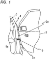
- FIG. 1 is a view for illustrating a state in which a vehicle door 2 is opened, as viewed from a rear side of a vehicle 1.
- FIG. 2A is a view for illustrating a check link 5 and a door check 6 under a state in which the vehicle door 2 is closed.
- FIG. 2B is a view for illustrating motions of the check link 5 and the door check 6 under a state in which the vehicle door 2 is opened.
- the vehicle door 2 is supported on a body 3 at hinge portions 2a, which are arranged on a front side of the vehicle door 2, so as to be pivotable about a pivot axis 4.
- the check link 5 is mounted in the vicinity of the hinge portions 2a of the vehicle door 2.
- FIG. 2A is a view for illustrating the check link 5 under the state in which the vehicle door 2 is closed
- FIG. 2B is a view for illustrating the check link 5 under the state in which the vehicle door 2 is opened.
- the check link 5 has an elongated shape, and one end 5a of the check link 5 is supported on the body 3 so as to be pivotable. Another end 5b of the check link 5, which is arranged on a side opposite to the one end 5a supported on the body 3, is inserted into the vehicle door 2 through a hole formed in a wall surface of the vehicle door 2 on a side on which the hinge portions 2a of the vehicle door 2 are arranged.
- a stopper member 7 having a flange shape is mounted to another end of the check link 5.
- the door check 6 having a through-hole formed therein is mounted on an inner wall 2b of the vehicle door 2.
- the check link 5 is inserted through the through-hole of the door check 6 so that the door check 6 is positioned between the one end 5a and the another end 5b of the check link 5.
- Pressing members 8 each configured to press a surface of the check link 5 are arranged inside the door check 6. As illustrated in FIG. 2B , when the vehicle door 2 is opened, the check link 5 is pivoted with respect to the body 3.
- a position of the door check 6 is shifted relative to the check link 5, and the pressing members 8 of the door check 6 can move relative to the check link 5 within a predetermined movable range between the one end 5a and the another end 5b of the check link 5 while pressing the check link 5. Meanwhile, when the vehicle door is closed, the door check 6 and the pressing members 8 are returned to original states through reverse procedures.
- FIG. 3 is a view for illustrating the opening angles of the vehicle door 2 and positions A to E of the door check 6 in an extending direction of the check link 5.
- the vehicle door 2 is in the closed state.
- the vehicle door 2 is opened (popped up) under a state in which only a resilient force of a rubber weather strip arranged between the vehicle door 2 and the body 3 is exerted.
- the vehicle door 2 is in a spontaneous open state with a maximum opening degree under no load.
- the vehicle door 2 When the door check 6 is at the position C, the vehicle door 2 is in the open state at a minimum opening angle enabling an occupant to get on or off the vehicle.
- the vehicle door 2 When the door check 6 is at the position D, the vehicle door 2 is opened at an opening angle enabling an occupant to easily get on or off the vehicle.
- the vehicle door 2 When the door check 6 is at the position E, the vehicle door 2 is fully opened at a maximum angle. That is, when the door check 6 is at the position closer to the stopper member 7, that is, on the another end 5b side of the check link 5, the vehicle door 2 is in a more open state.
- the vehicle door 2 When the door check 6 is at the position more distant from the stopper member 7, that is, on the one end 5a side of the check link 5, the vehicle door 2 is in a more closed state.
- FIG. 4A to FIG. 4D are illustrations of the check link 5 and the door check 6.
- the one end 5a of the check link 5 is retained on the body 3 so as to be pivotable, and the stopper member 7 is mounted on the another end 5b of the check link 5.
- Elastic members 9 are arranged inside the door check 6.
- the check link 5 includes one sliding surface extending in the extending direction of the check link 5.
- Each of the elastic members 9 urges the pressing member 8 so as to cause the pressing member 8 to press the sliding surface of the check link 5.
- two sliding surfaces be arranged on the check link 5 so as to be opposite to each other.
- the pair of elastic members 9 and the pair of pressing members 8 are arranged inside the door check 6 so as to press and sandwich the two sliding surfaces from both sides of the check link 5.
- the door check 6 is mounted on an inner surface 2b of the vehicle door 2 so that a pressing direction of the pressing member 8 is substantially perpendicular to a direction in which the check link 5 extends.
- the door check 6 includes a regulation surface 6a arranged on the another end side of the check link 5 so as to be perpendicular to the extending direction of the check link 5.
- the stopper member 7 includes a surface parallel to the regulation surface 6a.
- the opening degree adjustment device for a vehicle door includes an opening degree adjustment block 10.
- the opening degree adjustment block 10 is retained by a retaining bracket 11 mounted on the regulation surface 6a of the door check 6.
- the opening degree adjustment block 10 has a predetermined length in the extending direction of the check link 5, and can be fitted on the check link 5.
- the opening degree adjustment block 10 includes a tab 12 and a surface that are capable of coming into abutment against the retaining bracket 11 and the stopper member 7, respectively, when the opening degree adjustment block 10 is fitted on the check link 5.
- the opening degree adjustment block 10 includes a first checking region and a second checking region.
- the first checking region is defined by a pair of abutment surfaces so as to determine a movement restriction range having a first length (L1) in the extending direction of the check link 5
- the second checking region is defined by another pair of abutment surfaces so as to determine a movement restriction range having a second length (L2) in the extending direction of the check link 5.
- a range between a long-side end portion 10a of the opening degree adjustment block 10 on the another end 5b side of the check link 5 positioned on the stopper member 7 side when the opening degree adjustment block 10 is fitted on the check link 5, and the tab 12 arranged away from the long-side end portion 10a of the opening degree adjustment block 10 by a predetermined distance can be defined as the first movement restriction range having the first length (L1).
- a range between a short-side end portion 10c of the opening degree adjustment block 10 on the another end 5b side of the check link 5 positioned on the stopper member 7 side when the opening degree adjustment block 10 is fitted on the check link 5, and the tab 12 of the opening degree adjustment block 10 can be defined as the second movement restriction range having the second length (L2).
- the second length (L2) is defined as a length smaller than the first length (L1).
- a position of the opening degree adjustment block 10 can be controlled, for example, in such a manner that a user sets a setting device such as a dial arranged on the vehicle door 2.
- the opening degree adjustment block 10 is controlled so as to be movable among a first state in which the opening degree adjustment block 10 retreats to a position away from the check link, a second state in which the first checking region of the adjusting block 10 is fitted on a portion of the check link 5 within a predetermined movable range, and a third state in which the second checking region of the adjusting block 10 is fitted on a portion of the check link 5 within the predetermined movable range.
- the first checking region and the second checking region have the following relationship.
- the opening degree adjustment block 10 functions so as to restrict movement of the check link 5 in a direction of the one end 5a of the check link 5.
- the second checking region determines the second movement restriction range having the second length (L2)
- the stopper member 7 comes into abutment against the short-side end portion 10c of the opening degree adjustment block 10
- the tab 12 of the opening degree adjustment block comes into abutment against the retaining bracket.
- the opening degree adjustment block 10 functions so as to restrict movement of the check link 5 in the direction of the one end 5a of the check link 5. Therefore, as compared to the first state in which the check link 5 can move relative to the door check 6 within the predetermined movable range because the opening degree adjustment block 10 is not fitted on the check link 5, in the second state, the check link 5 can move relative to the door check 6 within a range reduced from the predetermined movable range by the first length (L1). Further, in the third state, the check link 5 can move relative to the door check 6 within a range reduced from the predetermined movable range by the second length (L2) smaller than the first length (L1).
- the range between the long-side end portion 10a and the tab 12 of the opening degree adjustment block 10 is set as the first movement restriction range having the first length (L1)
- the range between the short-side end portion 10c and the tab 12 of the opening degree adjustment block 10 is set as the second movement restriction range having the second length (L2).
- the movement restriction ranges can be defined in various manners. For example, instead of the tab 12, an end portion 10b of the opening degree adjustment block 10 on the one end 5a side of the check link 5 may be used.
- a range between the long-side end portion 10a of the opening degree adjustment block 10 and the end portion 10b of the opening degree adjustment block 10 on the one end 5a side of the check link 5 may be defined as the movement restriction range having the first length (L1).
- a range between the short-side end portion 10c of the opening degree adjustment block 10 and the end portion 10b of the opening degree adjustment block 10 on the one end 5a side of the check link 5 may be defined as the movement restriction range having the second length (L2).
- a protrusion or the like may be formed on the check link 5 on the one end 5a side of the check link 5 with respect to the stopper member 7, and the protrusion may come into abutment against the long-side end portion 10a of the opening degree adjustment block 10 or against the short-side end portion 10b of the opening degree adjustment block 10.
- the protrusion and the opening degree adjustment block 10 may come into abutment against each other so that the opening degree adjustment block 10 may function so as to restrict movement of the check link 5 in the direction of the one end 5a of the check link 5.
- the end portion 10b of the opening degree adjustment block 10 on the one end 5a side of the check link 5 comes into direct abutment against the retaining bracket 11 so that movement of the opening degree adjustment block 10 is indirectly restricted by the door check 6.
- movement of the check link 5 in the direction of the one end 5a of the check link 5 is restricted.
- the end portion 10b of the opening degree adjustment block 10 may come into direct abutment against the regulation surface 6a of the door check 6 so that movement of the opening degree adjustment block 10 may be restricted by the door check 6.
- movement of the check link 5 in the direction of the one end 5a of the check link 5 may be restricted.
- the first checking region of the opening degree adjustment block 10 is fitted on a portion of the check link 5 within the predetermined movable range, with the result that the opening degree adjustment block 10 restricts relative movement of the check link 5 in the direction of the another end 5b to the door check 6.
- the check link 5 can move relative to the door check 6 within a range reduced by the first length (L1) from the predetermined movable range in which the door check 6 is allowed to move relative to the check link 5 in the first state.
- the second checking region of the opening degree adjustment block 10 is fitted on a portion of the check link 5 within the predetermined movable range, with the result that the opening degree adjustment block 10 restricts relative movement of the door check 6 in the direction of the another end 5b of the check link 5.
- the check link 5 can move relative to the door check 6 within a range reduced by the second length (L2) from the predetermined movable range in which the door check 6 is allowed to move relative to the check link 5 in the first state. That is, geometric shapes of the first checking region and the second checking region of the opening degree adjustment block 10, the first length (L1), portions determining the first length (L1), the second length (L2), and portions determining the second length (L2) can be freely set.
- FIG. 4A is an illustration of the second state.
- the opening degree adjustment block 10 secures the first length (L1) by which relative movement of the door check 6 to the check link 5 is restricted. That is, the tab 12 configured to restrict movement of the check link 5 is at the position C.
- the check link 5 and the door check 6 are arranged so that the minimum opening angle of the vehicle door 2 enabling an occupant to get on or off the vehicle is formed when the tab 12 is at the position C.
- FIG. 4B is an illustration of the third state.
- the opening degree adjustment block 10 secures the second length (L2) that is smaller than the first length (L1) and is a length by which relative movement of the door check 6 to the check link 5 is restricted. That is, the tab 12 configured to restrict movement of the check link 5 is at the position D. It is only necessary to arrange the check link 5 and the door check 6 on the vehicle door 2 and the body 3 so that the opening angle of the vehicle door 2 enabling an occupant to easily get on or off the vehicle is formed when the tab 12 is at the position D.
- FIG. 4C and FIG. 4D are illustrations of the first state in which the opening degree adjustment block 10 retreats from the check link 5.
- FIG. 4C is an illustration of a state in which the vehicle door is most opened
- FIG. 4D is an illustration of a state in which popping up of the vehicle door is finished.
- FIG. 4C a state in which the stopper member 7 is held in abutment on the retaining bracket 11 is illustrated.
- relative movement of the door check 6 to the check link 5 is restricted by abutment of the stopper member 7 on the retaining bracket 11.
- this is merely an example.
- a positional relationship between the stopper member 7 and the retaining bracket 11 when the opening degree of the vehicle door is maximum can be freely set based on a relationship between the opening degree of the vehicle door and the length of the check link. Accordingly, the vehicle door can be opened with the maximum opening degree under a state in which the stopper member 7 is not held in abutment against the retaining bracket 11.
- the stopper member 7 comes into abutment against the retaining bracket 11 when the vehicle door is opened with the maximum opening degree. It is only necessary to arrange the check link 5 and the door check 6 so that the vehicle door 2 is fully opened at a maximum angle when the stopper member 7 comes into abutment against the retaining bracket 11.
- an angle of the vehicle door can be set as appropriate in accordance with a corresponding position on the check link 5.
- an interval between a relative position of the door check 6 to the check link 5 under a state in which the vehicle door 2 is fully opened, and a relative position of the door check 6 to the check link 5 under a state in which the vehicle door 2 is fully closed corresponds to a predetermined movable range of the door check 6 with respect to the check link 5. That is, the vehicle door 2 can be freely opened and closed within a range corresponding to the predetermined movable range of the door check 6 with respect to the check link 5.
- an operator of the vehicle door 2 measures a distance between the vehicle and an object adjacent to the vehicle, and adjusts the opening degree of the vehicle door 2 based on the distance.
- an operator fits the opening degree adjustment block 10 on the check link 5 by the setting device.
- the opening degree adjustment block 10 is brought into the second state. That is, the door check 6 is allowed to move relative to the check link 5 within a range reduced from the predetermined movable range by the first movement restriction range having the first length (L1).
- the opening degree adjustment block 10 is brought into the third state. That is, the door check 6 is allowed to move relative to the check link 5 within a range reduced from the predetermined movable range by the second movement restriction range having the second length (L2).
- the first length (L1) is longer than the second length (L2). Accordingly, the movable range of the door check 6 with respect to the check link 5 in the second state is smaller than the movable range of the door check 6 with respect to the check link 5 in the third state.
- the sliding surface of the check link 5 may include a slope (first slope 5c) to be described below.
- the slope (first slope 5c) is formed so as to slant down to the one end 5a side of the check link 5 from a portion of the check link pressed by the pressing member 8 when relative movement of the check link 5 in the direction of the one end 5a of the check link 5 is restricted by the opening degree adjustment block 10 in the second state.
- the slope is formed on the sliding surface of the check link 5.
- the pressing member 8 presses the sliding surface of the check link 5, and thus conversely undergoes a reaction force from the slope.
- a component of a force of relatively shifting a position of the pressing member 8 to the one end 5a side of the check link 5 is generated, with the result that the vehicle door 2 is always urged in the direction of closing the vehicle door 2. That is, even when an operator brings the opening degree adjustment block 10 into the second state with an intention to adjust the opening degree of the vehicle door 2, the vehicle door 2 is not urged in a direction of opening the vehicle door 2.
- the slope may be further extended. That is, another slope (second slope 5d) is formed so as to slant down to the one end 5a side of the check link 5 from a portion of the check link pressed by the pressing member 8 when relative movement of the check link 5 in the direction of the one end 5a of the check link 5 is restricted by the opening degree adjustment block 10 in the third state. Further, the second slope 5d is formed on the sliding surface of the check link 5 so as to be continuous with the first slope 5c formed in the second state.
- second slope 5d is formed so as to slant down to the one end 5a side of the check link 5 from a portion of the check link pressed by the pressing member 8 when relative movement of the check link 5 in the direction of the one end 5a of the check link 5 is restricted by the opening degree adjustment block 10 in the third state.
- the second slope 5d is formed on the sliding surface of the check link 5 so as to be continuous with the first slope 5c formed in the second state.
- the second slope 5d is a slope slanting from a portion of the check link pressed by the pressing member 8 when relative movement of the check link 5 in the direction of the one end 5a of the check link 5 is restricted by the opening degree adjustment block 10 in the third state, to a portion of the check link pressed by the pressing member in the second state.
- the second slope 5d is formed on the sliding surface of the check link 5.
- the vehicle door 2 is set so that, when the adjusting block 10 is fitted on the check link 10 to restrict movement of the check link by the second length, the vehicle door 2 can be opened at an angle that is generally used for an occupant to get on or off the vehicle. Further, the vehicle door 2 is set so that, when the adjusting block 10 is fitted on the check link to restrict movement of the check link by the first length, the vehicle door 2 can be opened to a minimum necessary angle for an occupant to get on or off the vehicle.
- An angle of the first slope 5c and an angle of the second slope 5d may be equal to or different from each other.
- an inclination angle of the slope in a range between the position C and the position D illustrated in FIG. 3 is set to be larger than an inclination angle of the slope in a range between the position B and the position C.
- the sliding surface specifically, the sliding surface in the range between the position D and the position E illustrated in FIG. 3 , between the stopper member and the slope under a state in which the adjusting block 10 restricts movement of the door check 6 only to allow the door check 6 to move to a position determining the second length (L2) may be formed into a flat surface.
- the sliding surface specifically, the sliding surface in the range between the position A and the position B illustrated in FIG. 3 , of the check link 5 between the first slope to the one end 5a of the check link 5 may be formed into a flat surface.
- the first slope and the second slope be formed on each of the two opposed sliding surfaces of the check link 5. That is, also on a sliding surface (lower sliding surface) opposite to the sliding surface (upper sliding surface) of the check link 5, the first slope 5c and the second slope 5d are formed at the same positions (corresponding positions) in the extending direction of the check link 5 as the positions of the first slope 5c and the second slope 5d on the upper sliding surface.
- the first slope 5c and the second slope 5d exert effects even when the first slope 5c and the second slope 5d are formed on any one of the upper sliding surface and the lower sliding surface.
- a reaction force is applied from the slope to the pressing member, and has a component of a force of shifting a position of the pressing member 8 to the one end 5a side of the check link 5.
- the component of the force always urges the vehicle door 2 in the direction of closing the vehicle door 2.
Landscapes
- Engineering & Computer Science (AREA)
- Mechanical Engineering (AREA)
- Lock And Its Accessories (AREA)
- Power-Operated Mechanisms For Wings (AREA)
Abstract
Description
- The present invention relates to an opening degree adjustment device, which is configured to adjust an opening degree of a vehicle door of a vehicle such as a passenger car.
- In a case where there is no sufficient space between a vehicle and an object adjacent to the vehicle when a vehicle is stopped, it is necessary to prevent a vehicle door from coming into contact with the object. In such a case, when an occupant gets off the vehicle, the occupant pulls a vehicle door toward an inner side of the vehicle to prevent sudden opening of the vehicle door, and opens the vehicle door so as to prevent the vehicle door from coming into contact with the object adjacent to the vehicle. Accordingly, it is conceivable to provide the vehicle door with a maximum opening degree restricting function capable of setting a maximum opening degree of the vehicle door.
- PTL 1:
Japanese Patent Application Laid-Open No. 2003-118369 - Even in a case where the vehicle door is provided with the maximum opening degree restricting function, a simple way of setting the opening degree of the vehicle door is to allow a driver himself/herself to recognize a distance between the vehicle and the object adjacent to the vehicle through the senses and manually set the maximum opening degree. At this time, visual measurement of the distance by an operator of the vehicle door is imprecise. Thus, in some cases, a maximum opening angle by the maximum opening degree restricting function of the vehicle door is set to a larger opening angle. The vehicle door has a certain weight. Thus, when the operator gets on or off the vehicle in that state, the vehicle door is easily opened even with a slight force, with the result that the vehicle door comes into contact with the object adjacent to the vehicle. Accordingly, in this state, it is preferred that the vehicle door be urged in a direction of closing the vehicle door. In this context, in
Patent Literature 1, there is disclosed a door checker for an automobile, which is configured to prevent a door from being suddenly opened to an opening limit against intention of a user. However, the door checker has been made to achieve an object to prevent the door from being suddenly opened within an opening range from a middle opening degree to the opening limit, and there is no disclosure as to a configuration for restricting a maximum opening amount of the vehicle door during popping up of the vehicle door as initial operation. In order to achieve safe popping up of the vehicle door, it is preferred that the maximum opening amount of the vehicle door be restricted. - According to one embodiment of the present invention, there is provided an opening degree adjustment device for a vehicle door, including: a door check including a pressing member and being fixed to a vehicle door; a check link including a sliding surface to be pressed by the pressing member, one end being supported on the vehicle body so as to be pivotable, and another end having a stopper member mounted thereto, the check link being movable relative to the door check within a predetermined movable range of the check link between the one end of the check link and the another end of the check link under a state in which the sliding surface is pressed by the pressing member; and an opening degree adjustment block including a first checking region configured to restrict movement of the stopper member in a direction of the one end of the check link so as to enable the check link to move relatively to the door check within a range reduced from the predetermined movable range by a first length.
- Predetermined slopes are formed on the check link to always urge the vehicle door in the direction of closing the vehicle door. Thus, even when there is no sufficient space between the vehicle and the object adjacent to the vehicle, the maximum opening amount can be restricted, and the vehicle door is less liable to collide with the object.
-
-
FIG. 1 is a view for illustrating a vehicle under a state in which a vehicle door is opened, as viewed from a rear side of the vehicle. -
FIG. 2A is a view for illustrating a motion of a check link under a state in which the vehicle door is closed, as viewed from the upper side of the vehicle. -
FIG. 2B is a view for illustrating a motion of the check link under a state in which the vehicle door is opened, as viewed from the upper side of the vehicle. -
FIG. 3 is a view for illustrating opening angles of the vehicle door at respective positions on the check link according to a vehicle door opening degree adjustment device of the present invention. -
FIG. 4A is a view for illustrating a relationship between the check link and an opening degree adjustment block in a vehicle door opening/closing adjustment device according to the present invention under a second state in which a predetermined movable range of the check link is reduced by a first length. -
FIG. 4B is a view for illustrating a relationship between the check link and the opening degree adjustment block in the vehicle door opening/closing adjustment device according to the present invention under a third state in which the predetermined movable range of the check link is reduced by a second length. -
FIG. 4C is a view for illustrating a relationship between the check link and the opening degree adjustment block in the vehicle door opening/closing adjustment device according to the present invention when the vehicle door is fully opened under a first state in which an opening degree adjustment block retreats. -
FIG. 4D is a view for illustrating a relationship between the check link and the opening degree adjustment block in the vehicle door opening/closing adjustment device according to the present invention when the poping up operation of the vehicle door is finished under the first state in which the opening degree adjustment block retreats. - Now, with reference to
FIG. 1 to FIG. 3 andFIG. 4A to FIG. 4D , an opening degree adjustment device for a vehicle door according to an embodiment of the present invention is described.FIG. 1 is a view for illustrating a state in which avehicle door 2 is opened, as viewed from a rear side of avehicle 1.FIG. 2A is a view for illustrating acheck link 5 and adoor check 6 under a state in which thevehicle door 2 is closed.FIG. 2B is a view for illustrating motions of thecheck link 5 and thedoor check 6 under a state in which thevehicle door 2 is opened. - In general, the
vehicle door 2 is supported on abody 3 athinge portions 2a, which are arranged on a front side of thevehicle door 2, so as to be pivotable about a pivot axis 4. In order to adjust an opening degree of the door, thecheck link 5 is mounted in the vicinity of thehinge portions 2a of thevehicle door 2. -
FIG. 2A is a view for illustrating thecheck link 5 under the state in which thevehicle door 2 is closed, andFIG. 2B is a view for illustrating thecheck link 5 under the state in which thevehicle door 2 is opened. Thecheck link 5 has an elongated shape, and oneend 5a of thecheck link 5 is supported on thebody 3 so as to be pivotable. Anotherend 5b of thecheck link 5, which is arranged on a side opposite to the oneend 5a supported on thebody 3, is inserted into thevehicle door 2 through a hole formed in a wall surface of thevehicle door 2 on a side on which thehinge portions 2a of thevehicle door 2 are arranged. Astopper member 7 having a flange shape is mounted to another end of thecheck link 5. - The
door check 6 having a through-hole formed therein is mounted on aninner wall 2b of thevehicle door 2. Thecheck link 5 is inserted through the through-hole of thedoor check 6 so that thedoor check 6 is positioned between the oneend 5a and the anotherend 5b of thecheck link 5. Pressingmembers 8 each configured to press a surface of thecheck link 5 are arranged inside thedoor check 6. As illustrated inFIG. 2B , when thevehicle door 2 is opened, thecheck link 5 is pivoted with respect to thebody 3. With this, a position of thedoor check 6 is shifted relative to thecheck link 5, and the pressingmembers 8 of thedoor check 6 can move relative to thecheck link 5 within a predetermined movable range between the oneend 5a and the anotherend 5b of thecheck link 5 while pressing thecheck link 5. Meanwhile, when the vehicle door is closed, thedoor check 6 and thepressing members 8 are returned to original states through reverse procedures. - As illustrated in
FIG. 3 , opening angles of thevehicle door 2 can be set in accordance with positions of thedoor check 6 within thecheck link 5.FIG. 3 is a view for illustrating the opening angles of thevehicle door 2 and positions A to E of thedoor check 6 in an extending direction of thecheck link 5. When thedoor check 6 is at the position A, thevehicle door 2 is in the closed state. When thedoor check 6 is shifted from the position A to the position B, thevehicle door 2 is opened (popped up) under a state in which only a resilient force of a rubber weather strip arranged between thevehicle door 2 and thebody 3 is exerted. When thedoor check 6 is at the position B, thevehicle door 2 is in a spontaneous open state with a maximum opening degree under no load. When thedoor check 6 is at the position C, thevehicle door 2 is in the open state at a minimum opening angle enabling an occupant to get on or off the vehicle. When thedoor check 6 is at the position D, thevehicle door 2 is opened at an opening angle enabling an occupant to easily get on or off the vehicle. When thedoor check 6 is at the position E, thevehicle door 2 is fully opened at a maximum angle. That is, when thedoor check 6 is at the position closer to thestopper member 7, that is, on the anotherend 5b side of thecheck link 5, thevehicle door 2 is in a more open state. When thedoor check 6 is at the position more distant from thestopper member 7, that is, on the oneend 5a side of thecheck link 5, thevehicle door 2 is in a more closed state. - With reference to
FIG. 4A to FIG. 4D , the opening degree adjustment device for a vehicle door, which is configured to achieve the states at the respective positions, is described.FIG. 4A to FIG. 4D are illustrations of thecheck link 5 and thedoor check 6. As described above, the oneend 5a of thecheck link 5 is retained on thebody 3 so as to be pivotable, and thestopper member 7 is mounted on the anotherend 5b of thecheck link 5.Elastic members 9 are arranged inside thedoor check 6. Thecheck link 5 includes one sliding surface extending in the extending direction of thecheck link 5. Each of theelastic members 9 urges thepressing member 8 so as to cause thepressing member 8 to press the sliding surface of thecheck link 5. As illustrated inFIG. 4A to FIG. 4D , it is preferred that two sliding surfaces be arranged on thecheck link 5 so as to be opposite to each other. The pair ofelastic members 9 and the pair of pressingmembers 8 are arranged inside thedoor check 6 so as to press and sandwich the two sliding surfaces from both sides of thecheck link 5. - The
door check 6 is mounted on aninner surface 2b of thevehicle door 2 so that a pressing direction of thepressing member 8 is substantially perpendicular to a direction in which thecheck link 5 extends. Thedoor check 6 includes aregulation surface 6a arranged on the another end side of thecheck link 5 so as to be perpendicular to the extending direction of thecheck link 5. Thestopper member 7 includes a surface parallel to theregulation surface 6a. - The opening degree adjustment device for a vehicle door includes an opening
degree adjustment block 10. The openingdegree adjustment block 10 is retained by a retainingbracket 11 mounted on theregulation surface 6a of thedoor check 6. The openingdegree adjustment block 10 has a predetermined length in the extending direction of thecheck link 5, and can be fitted on thecheck link 5. The openingdegree adjustment block 10 includes atab 12 and a surface that are capable of coming into abutment against the retainingbracket 11 and thestopper member 7, respectively, when the openingdegree adjustment block 10 is fitted on thecheck link 5. For example, in this embodiment, the openingdegree adjustment block 10 includes a first checking region and a second checking region. When the openingdegree adjustment block 10 is fitted on thecheck link 5, the first checking region is defined by a pair of abutment surfaces so as to determine a movement restriction range having a first length (L1) in the extending direction of thecheck link 5, and the second checking region is defined by another pair of abutment surfaces so as to determine a movement restriction range having a second length (L2) in the extending direction of thecheck link 5. For example, a range between a long-side end portion 10a of the openingdegree adjustment block 10 on the anotherend 5b side of thecheck link 5 positioned on thestopper member 7 side when the openingdegree adjustment block 10 is fitted on thecheck link 5, and thetab 12 arranged away from the long-side end portion 10a of the openingdegree adjustment block 10 by a predetermined distance can be defined as the first movement restriction range having the first length (L1). Meanwhile, for example, a range between a short-side end portion 10c of the openingdegree adjustment block 10 on the anotherend 5b side of thecheck link 5 positioned on thestopper member 7 side when the openingdegree adjustment block 10 is fitted on thecheck link 5, and thetab 12 of the openingdegree adjustment block 10 can be defined as the second movement restriction range having the second length (L2). Herein, the second length (L2) is defined as a length smaller than the first length (L1). - A position of the opening
degree adjustment block 10 can be controlled, for example, in such a manner that a user sets a setting device such as a dial arranged on thevehicle door 2. Through the setting, the openingdegree adjustment block 10 is controlled so as to be movable among a first state in which the openingdegree adjustment block 10 retreats to a position away from the check link, a second state in which the first checking region of the adjustingblock 10 is fitted on a portion of thecheck link 5 within a predetermined movable range, and a third state in which the second checking region of the adjustingblock 10 is fitted on a portion of thecheck link 5 within the predetermined movable range. In the second state and the third state, the first checking region and the second checking region have the following relationship. That is, when the first checking region determines the first movement restriction range having the first length (L1), thestopper member 7 comes into abutment on the long-side end portion of the openingdegree adjustment block 10, whereas thetab 12 of the opening degree adjustment block comes into abutment on the retaining bracket. As a result, the openingdegree adjustment block 10 functions so as to restrict movement of thecheck link 5 in a direction of the oneend 5a of thecheck link 5. Further, similarly, when the second checking region determines the second movement restriction range having the second length (L2), thestopper member 7 comes into abutment against the short-side end portion 10c of the openingdegree adjustment block 10, whereas thetab 12 of the opening degree adjustment block comes into abutment against the retaining bracket. As a result, the openingdegree adjustment block 10 functions so as to restrict movement of thecheck link 5 in the direction of the oneend 5a of thecheck link 5. Therefore, as compared to the first state in which thecheck link 5 can move relative to thedoor check 6 within the predetermined movable range because the openingdegree adjustment block 10 is not fitted on thecheck link 5, in the second state, thecheck link 5 can move relative to thedoor check 6 within a range reduced from the predetermined movable range by the first length (L1). Further, in the third state, thecheck link 5 can move relative to thedoor check 6 within a range reduced from the predetermined movable range by the second length (L2) smaller than the first length (L1). - In the above description, the range between the long-
side end portion 10a and thetab 12 of the openingdegree adjustment block 10 is set as the first movement restriction range having the first length (L1), and the range between the short-side end portion 10c and thetab 12 of the openingdegree adjustment block 10 is set as the second movement restriction range having the second length (L2). However, the movement restriction ranges can be defined in various manners. For example, instead of thetab 12, anend portion 10b of the openingdegree adjustment block 10 on the oneend 5a side of thecheck link 5 may be used. That is, a range between the long-side end portion 10a of the openingdegree adjustment block 10 and theend portion 10b of the openingdegree adjustment block 10 on the oneend 5a side of thecheck link 5 may be defined as the movement restriction range having the first length (L1). Similarly, a range between the short-side end portion 10c of the openingdegree adjustment block 10 and theend portion 10b of the openingdegree adjustment block 10 on the oneend 5a side of thecheck link 5 may be defined as the movement restriction range having the second length (L2). - In addition, instead of the configuration in which the short-
side end portion 10a of the openingdegree adjustment block 10 comes into direct abutment against thestopper member 7, a protrusion or the like may be formed on thecheck link 5 on the oneend 5a side of thecheck link 5 with respect to thestopper member 7, and the protrusion may come into abutment against the long-side end portion 10a of the openingdegree adjustment block 10 or against the short-side end portion 10b of the openingdegree adjustment block 10. In the second state and the third state, the protrusion and the openingdegree adjustment block 10 may come into abutment against each other so that the openingdegree adjustment block 10 may function so as to restrict movement of thecheck link 5 in the direction of the oneend 5a of thecheck link 5. Further, theend portion 10b of the openingdegree adjustment block 10 on the oneend 5a side of thecheck link 5 comes into direct abutment against the retainingbracket 11 so that movement of the openingdegree adjustment block 10 is indirectly restricted by thedoor check 6. Thus, movement of thecheck link 5 in the direction of the oneend 5a of thecheck link 5 is restricted. However, theend portion 10b of the openingdegree adjustment block 10 may come into direct abutment against theregulation surface 6a of thedoor check 6 so that movement of the openingdegree adjustment block 10 may be restricted by thedoor check 6. Thus, movement of thecheck link 5 in the direction of the oneend 5a of thecheck link 5 may be restricted. - In any cases, in the second state, the first checking region of the opening
degree adjustment block 10 is fitted on a portion of thecheck link 5 within the predetermined movable range, with the result that the openingdegree adjustment block 10 restricts relative movement of thecheck link 5 in the direction of the anotherend 5b to thedoor check 6. With this configuration, thecheck link 5 can move relative to thedoor check 6 within a range reduced by the first length (L1) from the predetermined movable range in which thedoor check 6 is allowed to move relative to thecheck link 5 in the first state. Further, in the third state, the second checking region of the openingdegree adjustment block 10 is fitted on a portion of thecheck link 5 within the predetermined movable range, with the result that the openingdegree adjustment block 10 restricts relative movement of thedoor check 6 in the direction of the anotherend 5b of thecheck link 5. With this configuration, thecheck link 5 can move relative to thedoor check 6 within a range reduced by the second length (L2) from the predetermined movable range in which thedoor check 6 is allowed to move relative to thecheck link 5 in the first state. That is, geometric shapes of the first checking region and the second checking region of the openingdegree adjustment block 10, the first length (L1), portions determining the first length (L1), the second length (L2), and portions determining the second length (L2) can be freely set. In the second state, it is only necessary that a relative movable range of thedoor check 6 to thecheck link 5 be reduced by the arbitrary first length (L1) from the predetermined movable range in which thedoor check 6 is allowed to move relative to thecheck link 5 in the first state. Further, in the third state, it is only necessary that a relative movable range of thedoor check 6 to thecheck link 5 be reduced by the second length (L2) from the predetermined movable range in which thedoor check 6 is allowed to move relative to thecheck link 5 in the first state. -
FIG. 4A is an illustration of the second state. In the second state, between thetab 12 and the long-side end portion 10a of the openingdegree adjustment block 10, the openingdegree adjustment block 10 secures the first length (L1) by which relative movement of thedoor check 6 to thecheck link 5 is restricted. That is, thetab 12 configured to restrict movement of thecheck link 5 is at the position C. Thecheck link 5 and thedoor check 6 are arranged so that the minimum opening angle of thevehicle door 2 enabling an occupant to get on or off the vehicle is formed when thetab 12 is at the position C. Further, similarly,FIG. 4B is an illustration of the third state. In the third state, between thetab 12 and the short-side end portion 10c of the openingdegree adjustment block 10, the openingdegree adjustment block 10 secures the second length (L2) that is smaller than the first length (L1) and is a length by which relative movement of thedoor check 6 to thecheck link 5 is restricted. That is, thetab 12 configured to restrict movement of thecheck link 5 is at the position D. It is only necessary to arrange thecheck link 5 and thedoor check 6 on thevehicle door 2 and thebody 3 so that the opening angle of thevehicle door 2 enabling an occupant to easily get on or off the vehicle is formed when thetab 12 is at the position D. -
FIG. 4C andFIG. 4D are illustrations of the first state in which the openingdegree adjustment block 10 retreats from thecheck link 5. In this state,FIG. 4C is an illustration of a state in which the vehicle door is most opened, andFIG. 4D is an illustration of a state in which popping up of the vehicle door is finished. InFIG. 4C , a state in which thestopper member 7 is held in abutment on the retainingbracket 11 is illustrated. However, in the state illustrated inFIG. 4C , relative movement of thedoor check 6 to thecheck link 5 is restricted by abutment of thestopper member 7 on the retainingbracket 11. However, this is merely an example. A positional relationship between thestopper member 7 and the retainingbracket 11 when the opening degree of the vehicle door is maximum can be freely set based on a relationship between the opening degree of the vehicle door and the length of the check link. Accordingly, the vehicle door can be opened with the maximum opening degree under a state in which thestopper member 7 is not held in abutment against the retainingbracket 11. In this specification, as one example, there is described an example in which thestopper member 7 comes into abutment against the retainingbracket 11 when the vehicle door is opened with the maximum opening degree. It is only necessary to arrange thecheck link 5 and thedoor check 6 so that thevehicle door 2 is fully opened at a maximum angle when thestopper member 7 comes into abutment against the retainingbracket 11. Further, it is only necessary to arrange thecheck link 5 and thedoor check 6 on thevehicle door 2 and thebody 3 so that thevehicle door 2 is fully opened at the maximum angle even under a state in which theregulation surface 6a is not held in abutment against thestopper member 7. An angle of the vehicle door can be set as appropriate in accordance with a corresponding position on thecheck link 5. In the first state, an interval between a relative position of thedoor check 6 to thecheck link 5 under a state in which thevehicle door 2 is fully opened, and a relative position of thedoor check 6 to thecheck link 5 under a state in which thevehicle door 2 is fully closed corresponds to a predetermined movable range of thedoor check 6 with respect to thecheck link 5. That is, thevehicle door 2 can be freely opened and closed within a range corresponding to the predetermined movable range of thedoor check 6 with respect to thecheck link 5. - Now, there is assumed a case where a user of the vehicle operates the
vehicle door 2 within a range corresponding to the range between the position D and the position E illustrated inFIG. 3 to get on or off the vehicle. In this case, there is a sufficient space between the vehicle and an object adjacent to the vehicle. Thus, there is no fear in that the vehicle door comes into contact with the object. Meanwhile, in a case where a user operates thevehicle door 2 within a range corresponding to the range between the position C and the position D illustrated inFIG. 3 to get on or off the vehicle, there is no sufficient space between the vehicle and the object adjacent to the vehicle. That is, the vehicle door may come into contact with the object. In this case, an operator of thevehicle door 2 measures a distance between the vehicle and an object adjacent to the vehicle, and adjusts the opening degree of thevehicle door 2 based on the distance. In view of a relationship of the measurement and adjustment to a position of thedoor check 6 in the extending direction of thecheck link 5, within the predetermined movable range of thedoor check 6 with respect to thecheck link 5, relative movement of thedoor check 6 to thecheck link 5 needs to be restricted. Accordingly, an operator fits the openingdegree adjustment block 10 on thecheck link 5 by the setting device. For example, in a case where an operator requires thevehicle door 2 to be slightly opened, that is, opened with a small opening degree, it is necessary to restrict the predetermined movable range of thedoor check 6 with respect to thecheck link 5 to a small range. In this case, as described above, the openingdegree adjustment block 10 is brought into the second state. That is, thedoor check 6 is allowed to move relative to thecheck link 5 within a range reduced from the predetermined movable range by the first movement restriction range having the first length (L1). Further, in a case where thevehicle door 2 is allowed to be opened with a larger opening degree than the above-mentioned small opening degree, but it is desired that the opening angle of thevehicle door 2 be restricted to an angle smaller than the maximum opening angle, the openingdegree adjustment block 10 is brought into the third state. That is, thedoor check 6 is allowed to move relative to thecheck link 5 within a range reduced from the predetermined movable range by the second movement restriction range having the second length (L2). The first length (L1) is longer than the second length (L2). Accordingly, the movable range of thedoor check 6 with respect to thecheck link 5 in the second state is smaller than the movable range of thedoor check 6 with respect to thecheck link 5 in the third state. - However, in a case where there is no sufficient space between the vehicle and the object adjacent to the vehicle, in general, an operator sets the opening degree of the vehicle door improperly in some cases because the operator sets the opening degree based on visual measurement of the distance between the vehicle and the object. The operator gets on or off the vehicle while measuring a distance between an end of the
vehicle door 2 and the object. In this case, when thevehicle door 2 is urged in a direction of closing thevehicle door 2, collision between thevehicle door 2 and the object adjacent to thevehicle door 2 can be avoided. Thus, this configuration is preferred. Accordingly, the sliding surface of thecheck link 5 may include a slope (first slope 5c) to be described below. That is, the slope (first slope 5c) is formed so as to slant down to the oneend 5a side of thecheck link 5 from a portion of the check link pressed by the pressingmember 8 when relative movement of thecheck link 5 in the direction of the oneend 5a of thecheck link 5 is restricted by the openingdegree adjustment block 10 in the second state. The slope is formed on the sliding surface of thecheck link 5. Thus, in this state, the pressingmember 8 presses the sliding surface of thecheck link 5, and thus conversely undergoes a reaction force from the slope. Thus, a component of a force of relatively shifting a position of thepressing member 8 to the oneend 5a side of thecheck link 5 is generated, with the result that thevehicle door 2 is always urged in the direction of closing thevehicle door 2. That is, even when an operator brings the openingdegree adjustment block 10 into the second state with an intention to adjust the opening degree of thevehicle door 2, thevehicle door 2 is not urged in a direction of opening thevehicle door 2. - Further, the slope may be further extended. That is, another slope (
second slope 5d) is formed so as to slant down to the oneend 5a side of thecheck link 5 from a portion of the check link pressed by the pressingmember 8 when relative movement of thecheck link 5 in the direction of the oneend 5a of thecheck link 5 is restricted by the openingdegree adjustment block 10 in the third state. Further, thesecond slope 5d is formed on the sliding surface of thecheck link 5 so as to be continuous with thefirst slope 5c formed in the second state. Accordingly, thesecond slope 5d is a slope slanting from a portion of the check link pressed by the pressingmember 8 when relative movement of thecheck link 5 in the direction of the oneend 5a of thecheck link 5 is restricted by the openingdegree adjustment block 10 in the third state, to a portion of the check link pressed by the pressing member in the second state. Thesecond slope 5d is formed on the sliding surface of thecheck link 5. Thus, even in the third state, the pressingmember 8 presses the sliding surface of thecheck link 5, and thus conversely undergoes a reaction force from the slope. Thus, a component of a force of relatively shifting a position of thepressing member 8 to the oneend 5a side of thecheck link 5 is generated, with the result that thevehicle door 2 is always urged in the direction of closing thevehicle door 2. That is, even when an operator brings the openingdegree adjustment block 10 into the third state with an intention to adjust the opening degree of thevehicle door 2, thevehicle door 2 is not urged in the direction of opening thevehicle door 2. - Further, it is only necessary to set the
vehicle door 2 so that thevehicle door 2 can be fully opened when the adjustingblock 10 is not fitted on thecheck link 5. In addition, thevehicle door 2 is set so that, when the adjustingblock 10 is fitted on thecheck link 10 to restrict movement of the check link by the second length, thevehicle door 2 can be opened at an angle that is generally used for an occupant to get on or off the vehicle. Further, thevehicle door 2 is set so that, when the adjustingblock 10 is fitted on the check link to restrict movement of the check link by the first length, thevehicle door 2 can be opened to a minimum necessary angle for an occupant to get on or off the vehicle. - An angle of the
first slope 5c and an angle of thesecond slope 5d may be equal to or different from each other. In a case where it is desired that a larger urging force be applied in the direction of closing thevehicle door 2 particularly under a state in which thevehicle door 2 is opened at a wider angle, an inclination angle of the slope in a range between the position C and the position D illustrated inFIG. 3 is set to be larger than an inclination angle of the slope in a range between the position B and the position C. - In contrast, when it is premised that the
vehicle door 2 is opened with a maximum opening degree, it is sometimes advantageous that thevehicle door 2 be not urged in the direction of closing thevehicle door 2. Therefore, under a state in which the adjustingblock 10 retreats from thecheck link 5, the sliding surface, specifically, the sliding surface in the range between the position D and the position E illustrated inFIG. 3 , between the stopper member and the slope under a state in which the adjustingblock 10 restricts movement of thedoor check 6 only to allow thedoor check 6 to move to a position determining the second length (L2) may be formed into a flat surface. - Meanwhile, in the case of the popping up of the
vehicle door 2, it is advantageous that thevehicle door 2 be not urged in the direction of closing thevehicle door 2. Accordingly, the sliding surface, specifically, the sliding surface in the range between the position A and the position B illustrated inFIG. 3 , of thecheck link 5 between the first slope to the oneend 5a of thecheck link 5 may be formed into a flat surface. - As in this embodiment, it is preferred that the first slope and the second slope be formed on each of the two opposed sliding surfaces of the
check link 5. That is, also on a sliding surface (lower sliding surface) opposite to the sliding surface (upper sliding surface) of thecheck link 5, thefirst slope 5c and thesecond slope 5d are formed at the same positions (corresponding positions) in the extending direction of thecheck link 5 as the positions of thefirst slope 5c and thesecond slope 5d on the upper sliding surface. However, thefirst slope 5c and thesecond slope 5d exert effects even when thefirst slope 5c and thesecond slope 5d are formed on any one of the upper sliding surface and the lower sliding surface. When one slope is formed at a predetermined position, a reaction force is applied from the slope to the pressing member, and has a component of a force of shifting a position of thepressing member 8 to the oneend 5a side of thecheck link 5. The component of the force always urges thevehicle door 2 in the direction of closing thevehicle door 2. - This application claims the benefit of priority from
Japanese Patent Application No. 2014-175773, filed on August 29, 2014 -
- 1
- vehicle
- 2
- vehicle door
- 3
- body
- 4
- pivot axis
- 5
- check link
- 6
- door check
- 7
- stopper member
- 8
- pressing member
- 9
- elastic member
- 10
- opening degree adjustment block
Claims (5)
- An opening degree adjustment device for a vehicle door, comprising:a door check comprising a pressing member and being fixed to a vehicle door mounted to a vehicle body so as to be pivotable;a check link comprising:a sliding surface to be pressed by the pressing member;one end being supported on the vehicle body so as to be pivotable; andanother end having a stopper member mounted thereon,the check link being movable relative to the door check within a predetermined movable range of the check link between the one end of the check link and the another end of the check link under a state in which the sliding surface is pressed by the pressing member; andan opening degree adjustment block comprising a first checking region configured to restrict movement of the stopper member in a direction of the one end of the check link so as to enable the check link to move relatively to the door check within a range reduced from the predetermined movable range by a first length,wherein the opening degree adjustment block is movable between a first state in which the opening degree adjustment block retreats to a position away from the check link to enable the check link to move relative to the door check within the predetermined movable range, and a second state in which the first checking region of the opening degree adjustment block is fitted on a portion of the check link within the predetermined movable range, and the opening degree adjustment block restricts movement of the check link in the direction of the one end of the check link, to thereby enable the check link to move relative to the door check within the range reduced from the predetermined movable range by the first length, andwherein the sliding surface of the check link comprises a first slope slanting down to the one end side of the check link from a portion of the check link pressed by the pressing member when the opening degree adjustment block restricts the relative movement of the check link in the direction of the one end of the check link in the second state.
- An opening degree adjustment device for a vehicle door according to claim 1,
wherein the opening degree adjustment block further comprises a second checking region configured to restrict movement of the stopper member in the direction of the one end of the check link so as to enable the check link to move relative to the door check within a range reduced from the predetermined movable range by a second length smaller than the first length,
wherein the opening degree adjustment block is further movable into a third state in which the second checking region of the opening degree adjustment block is fitted on a portion of the check link within the predetermined movable range, and the opening degree adjustment block restricts movement of the check link in the direction of the one end of the check link, to thereby enable the check link to move relative to the door check within the range reduced from the predetermined movable range by the second length, and
wherein the sliding surface of the check link comprises a second slope slanting down to the one end side of the check link and extending from a portion of the check link pressed by the pressing member when the opening degree adjustment block restricts the relative movement of the check link in the direction of the one end of the check link in the third state, to a portion of the check link pressed by the pressing member in the second state. - An opening degree adjustment device for a vehicle door according to claim 2,
wherein, in the first state, the vehicle door is set to be openable and closable between a fully opened state and a fully closed state,
wherein, in the third state, the vehicle door is set to be openable at an angle smaller than an angle in the fully opened state, and
wherein, in the second state, the vehicle door is set to be openable at an angle further smaller than the angle in the third state. - An opening degree adjustment device for a vehicle door according to any one of claims 1 to 3, wherein the check link comprises a flat surface between the first slope and the one end of the check link.
- An opening degree adjustment device for a vehicle door according to any one of claims 1 to 4,
wherein the check link comprises another sliding surface on an opposite side of the sliding surface that slides while being pressed by the pressing member,
wherein the pressing member is capable of pressing the sliding surface and the another sliding surface from both sides of the check link so as to sandwich both of the sliding surface and the another sliding surface, and
wherein the first slope and the second slope are formed on the another sliding surface at the same positions in an extending direction of the check link as positions of the first slope and the second slope on the sliding surface.
Applications Claiming Priority (2)
| Application Number | Priority Date | Filing Date | Title |
|---|---|---|---|
| JP2014175773A JP6337701B2 (en) | 2014-08-29 | 2014-08-29 | Vehicle door opening adjustment device |
| PCT/JP2015/004034 WO2016031161A1 (en) | 2014-08-29 | 2015-08-12 | Vehicle door opening degree adjustment device |
Publications (2)
| Publication Number | Publication Date |
|---|---|
| EP3187348A1 true EP3187348A1 (en) | 2017-07-05 |
| EP3187348A4 EP3187348A4 (en) | 2017-09-13 |
Family
ID=55399079
Family Applications (1)
| Application Number | Title | Priority Date | Filing Date |
|---|---|---|---|
| EP15835333.4A Withdrawn EP3187348A4 (en) | 2014-08-29 | 2015-08-12 | Vehicle door opening degree adjustment device |
Country Status (5)
| Country | Link |
|---|---|
| US (1) | US20170275933A1 (en) |
| EP (1) | EP3187348A4 (en) |
| JP (1) | JP6337701B2 (en) |
| CN (1) | CN106604840B (en) |
| WO (1) | WO2016031161A1 (en) |
Families Citing this family (4)
| Publication number | Priority date | Publication date | Assignee | Title |
|---|---|---|---|---|
| JP2981008B2 (en) | 1991-04-22 | 1999-11-22 | 大日本印刷株式会社 | Packaging material |
| JP3113092B2 (en) | 1992-09-22 | 2000-11-27 | 三菱化学株式会社 | Composite sheet for hot melt bonding |
| WO2015146754A1 (en) * | 2014-03-26 | 2015-10-01 | アイシン精機 株式会社 | Door opening degree adjustment device |
| US20170028966A1 (en) * | 2015-07-29 | 2017-02-02 | Ford Global Technologies, Llc | System and method for vehicle control based on detected door condition |
Family Cites Families (10)
| Publication number | Priority date | Publication date | Assignee | Title |
|---|---|---|---|---|
| JPS6311269Y2 (en) * | 1980-07-24 | 1988-04-01 | ||
| JPS63192566U (en) * | 1987-05-30 | 1988-12-12 | ||
| WO2006049540A1 (en) * | 2004-11-04 | 2006-05-11 | Volvo Lastvagnar Ab | Door braking device |
| US7739836B2 (en) * | 2005-06-07 | 2010-06-22 | Chrysler Group Llc | Vehicle door with selective full open positions |
| JP4474339B2 (en) * | 2005-07-15 | 2010-06-02 | 本田技研工業株式会社 | Automotive door checker |
| JP4657123B2 (en) * | 2006-02-28 | 2011-03-23 | シロキ工業株式会社 | Door checker device and stopper bracket |
| CN201436352U (en) * | 2009-08-04 | 2010-04-07 | 上海大众汽车有限公司 | car door stopper |
| JP5298302B2 (en) * | 2009-12-02 | 2013-09-25 | 日本発條株式会社 | Door check device |
| JP6019494B2 (en) * | 2011-10-07 | 2016-11-02 | 三井金属アクト株式会社 | Automotive door check device |
| WO2015146754A1 (en) * | 2014-03-26 | 2015-10-01 | アイシン精機 株式会社 | Door opening degree adjustment device |
-
2014
- 2014-08-29 JP JP2014175773A patent/JP6337701B2/en not_active Expired - Fee Related
-
2015
- 2015-08-12 CN CN201580046593.8A patent/CN106604840B/en not_active Expired - Fee Related
- 2015-08-12 EP EP15835333.4A patent/EP3187348A4/en not_active Withdrawn
- 2015-08-12 US US15/506,534 patent/US20170275933A1/en not_active Abandoned
- 2015-08-12 WO PCT/JP2015/004034 patent/WO2016031161A1/en not_active Ceased
Also Published As
| Publication number | Publication date |
|---|---|
| JP6337701B2 (en) | 2018-06-06 |
| EP3187348A4 (en) | 2017-09-13 |
| WO2016031161A1 (en) | 2016-03-03 |
| CN106604840A (en) | 2017-04-26 |
| US20170275933A1 (en) | 2017-09-28 |
| CN106604840B (en) | 2019-03-15 |
| JP2016049855A (en) | 2016-04-11 |
Similar Documents
| Publication | Publication Date | Title |
|---|---|---|
| EP3187348A1 (en) | Vehicle door opening degree adjustment device | |
| US7076833B2 (en) | Automobile door checker | |
| US10107020B2 (en) | Door opening degree adjustment device | |
| US10077584B2 (en) | Actuator | |
| US9003604B2 (en) | Door checker for automobile | |
| KR102108049B1 (en) | Buckled tongue | |
| US10647184B2 (en) | Sunroof apparatus | |
| US20250305338A1 (en) | Door device for vehicle | |
| US8898956B2 (en) | Sliding door device for vehicle with pressure sensing unit and sealing unit | |
| EP3124300B1 (en) | Sunroof device | |
| EP3269910A1 (en) | Vehicle handle device | |
| WO2014171195A1 (en) | Buckle for seatbelt device | |
| US20180050650A1 (en) | Vehicle airbag device | |
| JP6536257B2 (en) | Sunroof device | |
| US20180305959A1 (en) | Door striker assembly | |
| CN107489324B (en) | Door limiter devices for vehicles | |
| US9758025B2 (en) | Sunroof apparatus | |
| US20160280050A1 (en) | Sunshade device | |
| US10232803B2 (en) | Temporary placement structure for sub cover | |
| CN109955795B (en) | Vehicle fixed structure | |
| JP2007106233A (en) | Armrest structure | |
| EP2050905A2 (en) | Hinge device for tailgate glass | |
| CN205387061U (en) | Vehicle is with door | |
| US20160229275A1 (en) | Sunroof apparatus | |
| CN204126435U (en) | Large opening vehicle door stop |
Legal Events
| Date | Code | Title | Description |
|---|---|---|---|
| PUAI | Public reference made under article 153(3) epc to a published international application that has entered the european phase |
Free format text: ORIGINAL CODE: 0009012 |
|
| 17P | Request for examination filed |
Effective date: 20170313 |
|
| AK | Designated contracting states |
Kind code of ref document: A1 Designated state(s): AL AT BE BG CH CY CZ DE DK EE ES FI FR GB GR HR HU IE IS IT LI LT LU LV MC MK MT NL NO PL PT RO RS SE SI SK SM TR |
|
| AX | Request for extension of the european patent |
Extension state: BA ME |
|
| A4 | Supplementary search report drawn up and despatched |
Effective date: 20170814 |
|
| RIC1 | Information provided on ipc code assigned before grant |
Ipc: E05C 17/22 20060101ALI20170808BHEP Ipc: E05C 17/20 20060101ALI20170808BHEP Ipc: B60J 5/04 20060101AFI20170808BHEP |
|
| DAV | Request for validation of the european patent (deleted) | ||
| DAX | Request for extension of the european patent (deleted) | ||
| STAA | Information on the status of an ep patent application or granted ep patent |
Free format text: STATUS: THE APPLICATION HAS BEEN WITHDRAWN |
|
| 18W | Application withdrawn |
Effective date: 20190627 |