EP3187291A1 - Electrical portable drilling machine - Google Patents
Electrical portable drilling machine Download PDFInfo
- Publication number
- EP3187291A1 EP3187291A1 EP15382671.4A EP15382671A EP3187291A1 EP 3187291 A1 EP3187291 A1 EP 3187291A1 EP 15382671 A EP15382671 A EP 15382671A EP 3187291 A1 EP3187291 A1 EP 3187291A1
- Authority
- EP
- European Patent Office
- Prior art keywords
- driving means
- drilling machine
- longitudinal axis
- portable drilling
- control unit
- Prior art date
- Legal status (The legal status is an assumption and is not a legal conclusion. Google has not performed a legal analysis and makes no representation as to the accuracy of the status listed.)
- Granted
Links
- 238000005553 drilling Methods 0.000 title claims abstract description 133
- 239000000463 material Substances 0.000 claims description 57
- 230000008859 change Effects 0.000 claims description 14
- 238000005259 measurement Methods 0.000 claims description 4
- 230000009467 reduction Effects 0.000 claims description 2
- 238000000034 method Methods 0.000 description 15
- 230000008569 process Effects 0.000 description 14
- 238000006073 displacement reaction Methods 0.000 description 7
- 230000006870 function Effects 0.000 description 6
- 239000010936 titanium Substances 0.000 description 6
- 239000004918 carbon fiber reinforced polymer Substances 0.000 description 4
- 238000005461 lubrication Methods 0.000 description 4
- RTAQQCXQSZGOHL-UHFFFAOYSA-N Titanium Chemical compound [Ti] RTAQQCXQSZGOHL-UHFFFAOYSA-N 0.000 description 3
- VNWKTOKETHGBQD-UHFFFAOYSA-N methane Chemical compound C VNWKTOKETHGBQD-UHFFFAOYSA-N 0.000 description 3
- 229910052719 titanium Inorganic materials 0.000 description 3
- 229920000049 Carbon (fiber) Polymers 0.000 description 2
- 239000004917 carbon fiber Substances 0.000 description 2
- 230000032798 delamination Effects 0.000 description 2
- 239000000314 lubricant Substances 0.000 description 2
- 230000009471 action Effects 0.000 description 1
- XAGFODPZIPBFFR-UHFFFAOYSA-N aluminium Chemical compound [Al] XAGFODPZIPBFFR-UHFFFAOYSA-N 0.000 description 1
- 229910052782 aluminium Inorganic materials 0.000 description 1
- 238000004140 cleaning Methods 0.000 description 1
- 230000001143 conditioned effect Effects 0.000 description 1
- 230000008878 coupling Effects 0.000 description 1
- 238000010168 coupling process Methods 0.000 description 1
- 238000005859 coupling reaction Methods 0.000 description 1
- 230000007547 defect Effects 0.000 description 1
- 230000001419 dependent effect Effects 0.000 description 1
- 239000012634 fragment Substances 0.000 description 1
- 230000004044 response Effects 0.000 description 1
- 239000000565 sealant Substances 0.000 description 1
Images

Classifications
-
- B—PERFORMING OPERATIONS; TRANSPORTING
- B23—MACHINE TOOLS; METAL-WORKING NOT OTHERWISE PROVIDED FOR
- B23B—TURNING; BORING
- B23B45/00—Hand-held or like portable drilling machines, e.g. drill guns; Equipment therefor
- B23B45/008—Gear boxes, clutches, bearings, feeding mechanisms or like equipment
-
- B—PERFORMING OPERATIONS; TRANSPORTING
- B23—MACHINE TOOLS; METAL-WORKING NOT OTHERWISE PROVIDED FOR
- B23B—TURNING; BORING
- B23B2226/00—Materials of tools or workpieces not comprising a metal
- B23B2226/27—Composites
-
- B—PERFORMING OPERATIONS; TRANSPORTING
- B23—MACHINE TOOLS; METAL-WORKING NOT OTHERWISE PROVIDED FOR
- B23B—TURNING; BORING
- B23B2228/00—Properties of materials of tools or workpieces, materials of tools or workpieces applied in a specific manner
- B23B2228/36—Multi-layered
-
- B—PERFORMING OPERATIONS; TRANSPORTING
- B23—MACHINE TOOLS; METAL-WORKING NOT OTHERWISE PROVIDED FOR
- B23B—TURNING; BORING
- B23B2260/00—Details of constructional elements
- B23B2260/062—Electric motors
-
- B—PERFORMING OPERATIONS; TRANSPORTING
- B23—MACHINE TOOLS; METAL-WORKING NOT OTHERWISE PROVIDED FOR
- B23B—TURNING; BORING
- B23B2260/00—Details of constructional elements
- B23B2260/158—Worms and worm wheels
-
- B—PERFORMING OPERATIONS; TRANSPORTING
- B23—MACHINE TOOLS; METAL-WORKING NOT OTHERWISE PROVIDED FOR
- B23B—TURNING; BORING
- B23B2270/00—Details of turning, boring or drilling machines, processes or tools not otherwise provided for
- B23B2270/32—Use of electronics
-
- B—PERFORMING OPERATIONS; TRANSPORTING
- B23—MACHINE TOOLS; METAL-WORKING NOT OTHERWISE PROVIDED FOR
- B23B—TURNING; BORING
- B23B2270/00—Details of turning, boring or drilling machines, processes or tools not otherwise provided for
- B23B2270/48—Measuring or detecting
Definitions
- the present invention belongs to the field of portable drilling machines, more particularly, to the field of electric portable drilling machine with negative feedback, which allows controlling the drilling parameters.
- An ordinary drilling process of more than one different surface comprises the following steps. Firstly, the holes are drilled from smaller diameters to final diameter in several steps. Once holes are reamed to final diameter, the surfaces are separated and the holes of each surface are deburred, the exposed surfaces are cleaned, and an interposition sealant is applied in each surface. Finally, the surfaces shall be precisely located at the same position where they were drilled.
- the portable drilling machines can be pneumatic or electric, and in both cases do not have vibration or the vibration control is very limited. This is due to that:
- the invention provides a portable drilling machine comprising,
- the first and the second driving means are configured to generate any force, rotation, torque or displacement. Since a drill bit can be connected in a solidary manner to the first driving means, said connection, which is performed in a solidary manner, transfers any force, rotation, torque or displacement to the drill bit connected. Therefore due to this connection, the first driving means are configured to transfer any force, rotation, torque or displacement to the drill bit connected along the first longitudinal axis.
- the worm gear is connected in a solidary manner to the second driving means. Said connection transfers any force, rotation, torque or displacement to the worm gear. Therefore due to this connection, the second driving means are configured to transfer any force, rotation, torque or displacement to the worm gear connected along the second longitudinal axis.
- the adapter is mechanically connected to the worm gear. Since the adapter is mechanically connected to the worm gear, any force, rotation, torque or displacement that the worm gear receives, it is transferred to the adapter producing the first longitudinally movement along the second longitudinal axis.
- the adapter since the adapter is mechanically connected to the first driving means through the sleeve, the first longitudinally movement produces through the adapter the second longitudinally movement along the first longitudinal axis. Also, the adapter, through the sleeve, moves the first driving means along the first longitudinal axis. Therefore the adapter due to the mechanical connection above explained is configured to be displaced along a plane formed by the first and the second first longitudinal axis.
- first and second longitudinal axes are substantially parallel to each other.
- substantially parallel means that the angle between both axes is zero or approximately zero, being able the displacement of the different components of the portable drilling machine without variation of the configuration of the adapter.
- the disposition of elements of the portable drilling machine allows looseness between the couplings of the different parts of the portable drilling machine, and each variation in any of the first or second driving means is directly transferred to the drill bit. Additionally, this fact allows controlling the longitudinal vibration in the second longitudinal axis during the use of portable drilling machine, and controlling the torque applied by the second driving means without needing an additional gadget or device.
- vibration is understood as a longitudinal mechanical movement which propagates in a longitudinally way in the axis wherein the drill bit of the drilling machine is located.
- the second driving means are rotatory and are configured to provide a rotatory movement to the worm gear connected to the second driving means.
- the worm gear rotates about the second longitudinal axis due to the action of the second driving means.
- the adapter comprises a thread which provides the mechanically connection between the worm gear and the adapter. This mechanical connection forms a worn drive wherein while the worm gear rotates the adapter moves along the second longitudinal axis.
- the adapter moves along the second longitudinal axis in a first direction, and if the worn gear rotates in a counterclockwise direction, the adapter moves along the second longitudinal axis in a second direction.
- the first driving means are configured to provide a vibration to a drill bit connectable in a solidary manner to the first driving means.
- the portable drilling machine is configured to provide a countersinking to avoid waviness or other defects due to vibration while the drilling process.
- the first driving means are rotatory and are configured to provide a rotatory movement to a drill bit connectable in a solidary manner to the first driving means.
- the portable drilling machine comprises a control unit connected to the first driving means or to the second first driving means, or both.
- control unit is configured to measure a change power consumption of the first driving means in order to distinguish a change of a material being drilled by the portable drilling machine.
- this embodiment allows advantageously that the control unit changes the drilling parameters for each material on the stack optimizing the drilling process.
- the drilling parameters to be changed are torque and/or rotation speed.
- control unit is configured to measure at least one vibration that a drill bit connected in a solidary manner with the first driving means suffers during drilling a material.
- control unit is configured to apply a vibration through the first driving means in response to the at least one vibration measured.
- the control unit is configured to control the amplitude, the frequency and the wave shape of the vibration, eliminating the necessity of adding a mechanical element to the drilling machine as it is shown in the previous section.
- this leads to a better diameter tolerance control and a better roughness control.
- control unit is configured to measure a reduction in a power consumption of the first driving means in order to distinguish if a material has been drilled by the portable drilling machine.
- control unit is configured to detect when the drilling is finished and stop the lubrication, avoiding advantageously lubricant leaks inside the aircraft.
- the second driving means comprises at least one encoder connected to the control unit and configured to measure a number of loops performed by the worm gear.
- control unit is configured to determine the thickness of a material being drilled by the portable drilling machine, determining a drilling distance (DD) calculated from the number of loops measured by the encoder and measuring a change in the power consumption of the first driving means.
- DD drilling distance
- said embodiments allow controlling the drilled distance drilling in one step increasing the efficiency of the drilling and eliminating the necessity of disassembly for cleaning and deburring.
- control unit is configured to store drilling parameters.
- this embodiment allows programing vibration parameters, making possible change vibration parameters during drilling, and stop the vibration when it is not necessary or not recommended, increasing the efficiency of the drilling process.
- the drilling parameters are a first predetermined measurement of the thickness of a material to be drilled, or more than one predetermined measurement of the thickness of the different materials which comprises the material to be drilled, or both.
- these embodiments allow knowing the position of the drill bill inside the material to be drilled. Once the drill bit reached some position, the control unit turns off the lubrication of the portable drilling machine when it is drilling.
- these embodiments allow improving the lubrication control, because each material receives the correct lubrication.
- the portable drilling machine avoids that lubricant will be spilled inside the aircraft reducing the dirtying of the aircraft.
- control unit is configured to
- this embodiment allows detecting when the last millimeters of material are being drilled. This leads to reduced delamination when drilling a material, for example carbon fiber, owing to the fact that the control unit reduces the feed rate as required.
- the portable drilling machine comprises a distance sensor connected to the control unit, wherein the distance sensor is configured to measure the distance between an end of a drill bit mechanically connected to the first driving means and a material to be drilled.
- control unit is configured to control the approach of a bit connected to the first driving means, therefore, the drilling machine is configured to perform a fast approach of the drill bit reducing the drilling time, since the distance from the drill tip to the material can be introduced as a parameter.
- the first driving means and the second driving means are servomotors.
- the adapter comprises a gearbox.
- the portable drilling machine (1) comprises a first driving means (2).
- the first driving means (2) are a first servomotor (2).
- the first servomotor (2) is movable along a first longitudinal axis (3) and is configured to be connected in a solidary manner to a drill bit (4) along the first longitudinal axis (3). Additionally, the first servomotor (2) is configured to provide a rotatory movement to a drill bit (4). Therefore, when the first servomotor (2) is turned on the drill bit (4) rotates around the first longitudinal axis (3).
- the portable drilling machine (1) comprises a second driving means (5).
- the second driving means (5) are a second servomotor (5).
- the second servomotor (5) is arranged in a second longitudinal axis (6), wherein the first longitudinal axis (3) and the second longitudinal axis (6) are parallel to each other as it shown in figure 1 .
- the portable drilling machine (1) also comprises a worm gear (7) connected in a solidary manner to the second servomotor (5) along the second longitudinal axis (6). Additionally, the second servomotor (5) is configured to provide a rotatory movement to the worm gear (7). Therefore, when the second servomotor (5) is turned on the drill bit (4) rotates around the first longitudinal axis (3) in a clockwise direction or in a counterclockwise direction.
- the portable drilling machine (1) comprises an adapter (8) mechanically connected to the worm gear (7).
- the adapter (8) comprises a sleeve (9) mechanically connected to the first servomotor (2).
- the adapter (8) is configured to transfer the rotatory movement of the worm gear (7) in a first longitudinally movement along the second longitudinal axis (6) and to transfer said first longitudinally movement along the second longitudinal axis (6) in a second longitudinally movement along the first longitudinal axis (3) moving the first servomotor (2).
- the adapter (8) is mechanically connected to the worm gear (7) in such way that the mechanical connection forms a worm drive. Therefore, if the worm gear (7) rotates in a clockwise direction, the adapter (8) moves along the second longitudinal axis (6) in a first direction (10). Then, the adapter (8) transfers the first longitudinally movement through the sleeve (9) to the first servomotor (2) moving said first servomotor (2) along the first longitudinal axis (3) in a second direction (12).
- the adapter (8) moves along the second longitudinal axis (6) in a third direction (11). Then, the adapter (8) transfers the first longitudinally movement through the sleeve (9) to the first servomotor (2) moving said first servomotor (2) in a fourth direction (13).
- the portable drilling machine (1) comprises a box (14) and a handle (15).
- the box (14) is configured to protect the different components of the portable drilling machine (1) during the drilling
- the handle (15) is configured to provide a safety management of the portable drilling machine (1) during the drilling process by an operator.
- the portable drilling machine (1) has two handles (15), which provides an even safer management of the portable drilling machine (1) during a drilling process.
- the portable drilling machine (1) comprises a control unit connected to a distance sensor and to the first (2) and second (5) servomotors. Also, the control unit comprises display means, in particular, a display. Said control unit is configured to display through the display the information of the drilling process in real time.
- control unit comprises a user interface with a keyboard.
- the user interface is configured to store at least one predetermined drilling parameter in the memory unit.
- the at least one predetermined drilling parameter may be:
- the control unit is configured
- control unit is configured to measure a material change when drilling hybrid unions, or if the drilling has been performed, measuring a change power consumption of the first servomotor (2).
- a change of the power consumption in the first servomotor (2) could be originated by:
- control unit is configured to display through the display the information of the drilling process in real time.
- control unit is configured to manage the vibration originated in the drilling process.
- the Feed Rate (F) is the speed at which the drill bit (4) of the portable drilling machine (1) moves forward (second direction (12)) or backwards (fourth direction (13)), and a, b, ..., n, are the time intervals corresponding to each material.
- the first servomotor (2) is configured to provide vibrations in order to compensate the vibrations which a material produced during drilling, therefore, the feed-rate can be defined as a hybrid function which comprises:
- the spindle speed (N) is the drill bit (4) rotation speed, and a, b, ..., n, are the time intervals corresponding to each material.
- the control unit is configured to manage the vibration originated in the drilling process in two different ways: a) Predetermined countermeasures.
- the control unit has stored in its memory unit the following predetermined drilling parameters: the thickness of materials comprised in the surface to be drilled, the number of materials comprised in the surface to be drilled, the thickness of the surface to be drilled and the predetermined vibrations to apply for each material during drilling.
- the control unit applies a predetermined vibration stored in the memory unit associated to each material.
- the control unit determines the drilling distance (DD) from the number of loops measured by the encoder connected to the second servomotor (5) and comparing to the predetermined drilling parameters which indicates the thickness of materials comprised in the surface to be drilled and the thickness of the surface to be drilled. For example: Thickness of the surface to be drilled 10 mm Number of materials comprised in the surface 2 Thickness of the first material 7 mm Thickness of the second material 3 mm Counter vibration for the first material 2 N/m Counter vibration for the second material 1 N/m In this case, if the drilling distance is 5 mm, the control unit would apply a counter vibration of 2 N/m and if the drilling distance is 7 mm the control unit would apply a counter vibration of 2 N/m.
- the control unit measures the first servomotor (2) feedback, i.e. variations detected by the first servomotor (2) during drilling on the applied torque due to the power consumption of the first servomotor (2). Then, the control unit applies a corresponding negative feedback, i.e. a vibration with the same frequency and amplitude but with an opposite direction of the variations or vibrations measured.
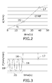
- Figures 2 and 3 show the drilling parameters measured by the control unit during the drilling.
- the surface to be drilled comprises two materials titanium (Ti) and carbon fiber reinforced plastic (CFRP).
- Ti titanium
- CFRP carbon fiber reinforced plastic
- the portable drilling machine (1) is configured to apply a vibration through the first servomotor (2) in order to countersinking the vibrations generated by the drilling.
- the vibration may have any amplitude, frequency or wave shape.
- the chosen feed rate is sinusoidal which implies a non-sinusoidal advance which implies a non-sinusoidal advance once the continuous component "v" is added.
- the movement of the drill bill (4) inside the surface to be drilled is conditioned by the feed rate, as it is shown in Figure 3 , but independent from spindle speed.
- the control unit is configured to control the vibration allowing the use of high speed peck drilling i.e. the drill is slightly retracted, breaking the chips. In this case the relationship between feed rate and revolutions is changed making possible to fragment ships when chips thickness is zero.
- the control of the vibration and the rest of the parameters allow increasing the efficiency and personalizing each drilling process for each material.
Landscapes
- Engineering & Computer Science (AREA)
- Mechanical Engineering (AREA)
- Drilling And Boring (AREA)
- Perforating, Stamping-Out Or Severing By Means Other Than Cutting (AREA)
Abstract
Description
- The present invention belongs to the field of portable drilling machines, more particularly, to the field of electric portable drilling machine with negative feedback, which allows controlling the drilling parameters.
- An ordinary drilling process of more than one different surface comprises the following steps. Firstly, the holes are drilled from smaller diameters to final diameter in several steps. Once holes are reamed to final diameter, the surfaces are separated and the holes of each surface are deburred, the exposed surfaces are cleaned, and an interposition sealant is applied in each surface. Finally, the surfaces shall be precisely located at the same position where they were drilled.
- This process is necessary due to the lack of vibration (or vibration control) and the intrinsic characteristics of the pneumatic and electric drilling.
- The portable drilling machines can be pneumatic or electric, and in both cases do not have vibration or the vibration control is very limited. This is due to that:
- Mechanic devices do not allow vibration frequency control.
- Mechanic devices only allow a sinusoidal vibration.
- Mechanic devices that have the capability of modifying the vibration amplitude use most of the volume of the drilling machine head.
- Piezoelectric vibration devices exist and can be additionally included in the drilling machine, but they require an additional device that transforms the piezoelectric vibration in the required vibration.
- Therefore, there is a need to find a portable drilling machine which do not need said additional devices and which improves the drilling process of more than one different surface.
- The present invention provides an alternative solution for the aforementioned problems, by a portable drilling machine according to
claim 1. In dependent claims, preferred embodiments of the invention are defined. - In a first inventive aspect, the invention provides a portable drilling machine comprising,
- a first driving means being movable along a first longitudinal axis, said first driving means being configured to be connected in a solidary manner to a drill bit along the first longitudinal axis,
- a second driving means arranged in a second longitudinal axis, the first longitudinal axis and the second longitudinal axis being substantially parallel to each other,
- a worm gear connected in a solidary manner to the second driving means along the second longitudinal axis,
- an adapter mechanically connected to the worm gear, said adapter comprising a sleeve mechanically connected to the first driving means,
- In this embodiment, the first and the second driving means are configured to generate any force, rotation, torque or displacement. Since a drill bit can be connected in a solidary manner to the first driving means, said connection, which is performed in a solidary manner, transfers any force, rotation, torque or displacement to the drill bit connected. Therefore due to this connection, the first driving means are configured to transfer any force, rotation, torque or displacement to the drill bit connected along the first longitudinal axis.
- In the same way that is explained in the previous paragraph, the worm gear is connected in a solidary manner to the second driving means. Said connection transfers any force, rotation, torque or displacement to the worm gear. Therefore due to this connection, the second driving means are configured to transfer any force, rotation, torque or displacement to the worm gear connected along the second longitudinal axis.
- The adapter is mechanically connected to the worm gear. Since the adapter is mechanically connected to the worm gear, any force, rotation, torque or displacement that the worm gear receives, it is transferred to the adapter producing the first longitudinally movement along the second longitudinal axis.
- Additionally, since the adapter is mechanically connected to the first driving means through the sleeve, the first longitudinally movement produces through the adapter the second longitudinally movement along the first longitudinal axis. Also, the adapter, through the sleeve, moves the first driving means along the first longitudinal axis. Therefore the adapter due to the mechanical connection above explained is configured to be displaced along a plane formed by the first and the second first longitudinal axis.
- As mentioned, the first and second longitudinal axes are substantially parallel to each other. In the context of the invention, substantially parallel means that the angle between both axes is zero or approximately zero, being able the displacement of the different components of the portable drilling machine without variation of the configuration of the adapter.
- Advantageously, the disposition of elements of the portable drilling machine allows looseness between the couplings of the different parts of the portable drilling machine, and each variation in any of the first or second driving means is directly transferred to the drill bit. Additionally, this fact allows controlling the longitudinal vibration in the second longitudinal axis during the use of portable drilling machine, and controlling the torque applied by the second driving means without needing an additional gadget or device.
- Throughout this document, vibration is understood as a longitudinal mechanical movement which propagates in a longitudinally way in the axis wherein the drill bit of the drilling machine is located.
- In a particular embodiment, the second driving means are rotatory and are configured to provide a rotatory movement to the worm gear connected to the second driving means.
- Advantageously, the worm gear rotates about the second longitudinal axis due to the action of the second driving means. In this embodiment, the adapter comprises a thread which provides the mechanically connection between the worm gear and the adapter. This mechanical connection forms a worn drive wherein while the worm gear rotates the adapter moves along the second longitudinal axis. In a particular embodiment, if the worm gear rotates in a clockwise direction, the adapter moves along the second longitudinal axis in a first direction, and if the worn gear rotates in a counterclockwise direction, the adapter moves along the second longitudinal axis in a second direction.
- In a particular embodiment, the first driving means are configured to provide a vibration to a drill bit connectable in a solidary manner to the first driving means.
- Advantageously, the portable drilling machine is configured to provide a countersinking to avoid waviness or other defects due to vibration while the drilling process.
- In a particular embodiment, the first driving means are rotatory and are configured to provide a rotatory movement to a drill bit connectable in a solidary manner to the first driving means.
- In a particular embodiment, the portable drilling machine comprises a control unit connected to the first driving means or to the second first driving means, or both.
- In a particular embodiment, the control unit is configured to measure a change power consumption of the first driving means in order to distinguish a change of a material being drilled by the portable drilling machine.
- Once the change of a material has been measured, this embodiment allows advantageously that the control unit changes the drilling parameters for each material on the stack optimizing the drilling process. In one embodiment, the drilling parameters to be changed are torque and/or rotation speed.
- In a particular embodiment, the control unit is configured to measure at least one vibration that a drill bit connected in a solidary manner with the first driving means suffers during drilling a material.
- In other embodiment, the control unit is configured to apply a vibration through the first driving means in response to the at least one vibration measured.
- The control unit is configured to control the amplitude, the frequency and the wave shape of the vibration, eliminating the necessity of adding a mechanical element to the drilling machine as it is shown in the previous section. Advantageously, this leads to a better diameter tolerance control and a better roughness control.
- In a particular embodiment, the control unit is configured to measure a reduction in a power consumption of the first driving means in order to distinguish if a material has been drilled by the portable drilling machine.
- In other embodiment the control unit is configured to detect when the drilling is finished and stop the lubrication, avoiding advantageously lubricant leaks inside the aircraft.
- In a particular embodiment, the second driving means comprises at least one encoder connected to the control unit and configured to measure a number of loops performed by the worm gear.
- In a particular embodiment, the control unit is configured to determine the thickness of a material being drilled by the portable drilling machine, determining a drilling distance (DD) calculated from the number of loops measured by the encoder and measuring a change in the power consumption of the first driving means.
- Advantageously, said embodiments allow controlling the drilled distance drilling in one step increasing the efficiency of the drilling and eliminating the necessity of disassembly for cleaning and deburring.
- In a particular embodiment, the control unit is configured to store drilling parameters.
- Advantageously this embodiment allows programing vibration parameters, making possible change vibration parameters during drilling, and stop the vibration when it is not necessary or not recommended, increasing the efficiency of the drilling process.
- In a particular embodiment, the drilling parameters are a first predetermined measurement of the thickness of a material to be drilled, or more than one predetermined measurement of the thickness of the different materials which comprises the material to be drilled, or both.
- Additionally, these embodiments allow knowing the position of the drill bill inside the material to be drilled. Once the drill bit reached some position, the control unit turns off the lubrication of the portable drilling machine when it is drilling.
- Advantageously, these embodiments allow improving the lubrication control, because each material receives the correct lubrication. As the standard aeronautical drilling is from outside to inside, the portable drilling machine avoids that lubricant will be spilled inside the aircraft reducing the dirtying of the aircraft.
- In a particular embodiment, the control unit is configured to
- determine when the drilling distance (DD) is greater than a threshold T, and
- when the drilling distance is greater than T, the control unit is also configured to reduce a torque of the first driving means.
- Advantageously, this embodiment allows detecting when the last millimeters of material are being drilled. This leads to reduced delamination when drilling a material, for example carbon fiber, owing to the fact that the control unit reduces the feed rate as required.
- In a particular embodiment, the portable drilling machine comprises a distance sensor connected to the control unit, wherein the distance sensor is configured to measure the distance between an end of a drill bit mechanically connected to the first driving means and a material to be drilled.
- Advantageously, the control unit is configured to control the approach of a bit connected to the first driving means, therefore, the drilling machine is configured to perform a fast approach of the drill bit reducing the drilling time, since the distance from the drill tip to the material can be introduced as a parameter.
- In a particular embodiment, the first driving means and the second driving means are servomotors.
- In a particular embodiment, the adapter comprises a gearbox.
- All the features described in this specification (including the claims, description and drawings) and/or all the steps of the described method can be combined in any combination, with the exception of combinations of such mutually exclusive features and/or steps.
- These and other characteristics and advantages of the invention will become clearly understood in view of the detailed description of the invention which becomes apparent from a preferred embodiment of the invention, given just as an example and not being limited thereto, with reference to the drawings.
-
Figure 1 This figure shows the components of a portable drilling machine according to the invention. -
Figure 2 This figure shows the change in the drilling parameters when a drill bit drills two different materials. -
Figure 3 This figure shows the feed rate and the vibration applied when different materials are drilled. - In this section particular embodiments of a portable drilling machine are described. The different components of the portable drilling machine can be appreciated in the
figure 1 . - The portable drilling machine (1) comprises a first driving means (2). In the embodiment of the
Figure 1 , the first driving means (2) are a first servomotor (2). The first servomotor (2) is movable along a first longitudinal axis (3) and is configured to be connected in a solidary manner to a drill bit (4) along the first longitudinal axis (3). Additionally, the first servomotor (2) is configured to provide a rotatory movement to a drill bit (4). Therefore, when the first servomotor (2) is turned on the drill bit (4) rotates around the first longitudinal axis (3). - The portable drilling machine (1) comprises a second driving means (5). In the embodiment of the
Figure 1 , the second driving means (5) are a second servomotor (5). The second servomotor (5) is arranged in a second longitudinal axis (6), wherein the first longitudinal axis (3) and the second longitudinal axis (6) are parallel to each other as it shown infigure 1 . - The portable drilling machine (1) also comprises a worm gear (7) connected in a solidary manner to the second servomotor (5) along the second longitudinal axis (6). Additionally, the second servomotor (5) is configured to provide a rotatory movement to the worm gear (7). Therefore, when the second servomotor (5) is turned on the drill bit (4) rotates around the first longitudinal axis (3) in a clockwise direction or in a counterclockwise direction.
- The portable drilling machine (1) comprises an adapter (8) mechanically connected to the worm gear (7). The adapter (8) comprises a sleeve (9) mechanically connected to the first servomotor (2). The adapter (8) is configured to transfer the rotatory movement of the worm gear (7) in a first longitudinally movement along the second longitudinal axis (6) and to transfer said first longitudinally movement along the second longitudinal axis (6) in a second longitudinally movement along the first longitudinal axis (3) moving the first servomotor (2).
- In this embodiment, the adapter (8) is mechanically connected to the worm gear (7) in such way that the mechanical connection forms a worm drive. Therefore, if the worm gear (7) rotates in a clockwise direction, the adapter (8) moves along the second longitudinal axis (6) in a first direction (10). Then, the adapter (8) transfers the first longitudinally movement through the sleeve (9) to the first servomotor (2) moving said first servomotor (2) along the first longitudinal axis (3) in a second direction (12).
- In case that the worm gear (7) rotates in a counterclockwise direction, the adapter (8) moves along the second longitudinal axis (6) in a third direction (11). Then, the adapter (8) transfers the first longitudinally movement through the sleeve (9) to the first servomotor (2) moving said first servomotor (2) in a fourth direction (13).
- The portable drilling machine (1) comprises a box (14) and a handle (15). The box (14) is configured to protect the different components of the portable drilling machine (1) during the drilling, and the handle (15) is configured to provide a safety management of the portable drilling machine (1) during the drilling process by an operator. In a particular embodiment, the portable drilling machine (1) has two handles (15), which provides an even safer management of the portable drilling machine (1) during a drilling process.
- The portable drilling machine (1) comprises a control unit connected to a distance sensor and to the first (2) and second (5) servomotors. Also, the control unit comprises display means, in particular, a display. Said control unit is configured to display through the display the information of the drilling process in real time.
- Additionally, the control unit comprises a user interface with a keyboard. The user interface is configured to store at least one predetermined drilling parameter in the memory unit. The at least one predetermined drilling parameter may be:
- The thickness of the surface to be drilled, for example, 10 mm.
- The number of materials comprised in the surface to be drilled, for example, number of materials comprised in the surface to be drilled is equal to 2.
- The type of materials comprised in the surface to be drilled, for example, titanium, aluminum, carbon fiber, etc.
- The thickness of materials comprised in the surface to be drilled, for example, the first material has a thickness of 3 mm and the second material has a thickness of 7 mm.
- The control unit is configured
- to manage drilling parameters provided by the components of the portable drilling machine (1),
- to calculate the remaining drilling distance according to
- ∘ the at least one predetermined drilling parameter, for example thickness of the surface to be drilled,
- ∘ a number of loops performed by the worm gear (7) and measured by a encoder attached to the second servomotor (5),
- to store the drilling parameters, the at least one predetermined drilling parameter and a log of the drilling process in a memory unit, for example, a SSD disk of 16 Gb.
- Additionally, the control unit is configured to measure a material change when drilling hybrid unions, or if the drilling has been performed, measuring a change power consumption of the first servomotor (2). A change of the power consumption in the first servomotor (2) could be originated by:
- A change of the material during drilling: A servomotor (2, 5) is configured to absorb any quantity of power from the electrical distribution network until said servomotor (2, 5) reaches its operational limit. This means that when drilling a harder material, the portable drilling machine (1) increases its power consumption in order to overcome the hardness of said material and maintain the speed of the worn gear (7).
- The drilling has been performed: If the power consumption of the first servomotor (2) is drastically reduced, it indicates that the drilling has been performed.
- Advantageously due to the drilling parameters received, the control unit is configured to display through the display the information of the drilling process in real time.
- Additionally, the control unit is configured to manage the vibration originated in the drilling process. From a mathematical point of view, the vibration may be considered as a function on a feed-rate and a spindle speed


- The Feed Rate (F) is the speed at which the drill bit (4) of the portable drilling machine (1) moves forward (second direction (12)) or backwards (fourth direction (13)), and a, b, ..., n, are the time intervals corresponding to each material. Advantageously, the first servomotor (2) is configured to provide vibrations in order to compensate the vibrations which a material produced during drilling, therefore, the feed-rate can be defined as a hybrid function which comprises:
- A continuous function wherein "v" represents the direct component of the speed at which the drill bit (4) of the portable drilling machine (1) moves forward.
- A non-continuous function wherein "A" and "f" is respectively the amplitude and the frequency, wherein "A" and "f" are components of the vibration provided by the first servomotor (2) in order to counteract the vibrations which a material produced during drilling. This function is not continuous because depends on the material, the amplitude (A) and/or the frequency (f) may be different, or even it could not necessary to provide a vibration to counteract the vibrations which a material produced during drilling, being the amplitude and the frequency in this case equal to zero.


- The spindle speed (N) is the drill bit (4) rotation speed, and a, b, ..., n, are the time intervals corresponding to each material.
- Therefore, the control unit is configured to manage the vibration originated in the drilling process in two different ways:
a) Predetermined countermeasures. In this embodiment, the control unit has stored in its memory unit the following predetermined drilling parameters: the thickness of materials comprised in the surface to be drilled, the number of materials comprised in the surface to be drilled, the thickness of the surface to be drilled and the predetermined vibrations to apply for each material during drilling.
During the drilling, the control unit applies a predetermined vibration stored in the memory unit associated to each material. For that propose, the control unit determines the drilling distance (DD) from the number of loops measured by the encoder connected to the second servomotor (5) and comparing to the predetermined drilling parameters which indicates the thickness of materials comprised in the surface to be drilled and the thickness of the surface to be drilled. For example:Thickness of the surface to be drilled 10 mm Number of materials comprised in the surface 2 Thickness of the first material 7 mm Thickness of the second material 3 mm Counter vibration for the first material 2 N/m Counter vibration for the second material 1 N/m
b) Direct countermeasures. In this embodiment, the control unit measures the first servomotor (2) feedback, i.e. variations detected by the first servomotor (2) during drilling on the applied torque due to the power consumption of the first servomotor (2). Then, the control unit applies a corresponding negative feedback, i.e. a vibration with the same frequency and amplitude but with an opposite direction of the variations or vibrations measured. -
Figures 2 and 3 show the drilling parameters measured by the control unit during the drilling. The surface to be drilled comprises two materials titanium (Ti) and carbon fiber reinforced plastic (CFRP). - While drilling, the portable drilling machine (1) is configured to apply a vibration through the first servomotor (2) in order to countersinking the vibrations generated by the drilling. The vibration may have any amplitude, frequency or wave shape. In this embodiment, the chosen feed rate is sinusoidal which implies a non-sinusoidal advance which implies a non-sinusoidal advance once the continuous component "v" is added. In
figures 2 and 3 the following features may be observed: - 1. When the Ti-CFRP interface is detected (16), the feed rate increases.
Figure 2 shows the hardest material (Ti) requires more power to maintain the torque and the speed than the softest material (CFRP).
In this stage as it is shown infigure 3 , the vibration provided by the first servomotor (2) is a hybrid function: non-continuous (a sinusoidal vibration (20)) and continuous (19) during the drilling of the titanium (Ti).
In a second stage, the vibration stops (18) due to the change of material as it is shown infigure 3 . The control unit is configured to stop the vibration provided by the first servomotor (2), if the material to be drilled do not need, for example, on carbon fiber composites. - 2. Spindle speed is different but constant on each material (
Figure 2 ). - 3. When the drilling end is detected (17), the feed rate is reduced in order to avoid delamination, but spindle speed remains constant.
- The movement of the drill bill (4) inside the surface to be drilled is conditioned by the feed rate, as it is shown in
Figure 3 , but independent from spindle speed. Advantageously, the control unit is configured to control the vibration allowing the use of high speed peck drilling i.e. the drill is slightly retracted, breaking the chips. In this case the relationship between feed rate and revolutions is changed making possible to fragment ships when chips thickness is zero. The control of the vibration and the rest of the parameters allow increasing the efficiency and personalizing each drilling process for each material.
Claims (15)
- A portable drilling machine (1) comprising,- a first driving means (2) being movable along a first longitudinal axis (3), said first driving means (2) being configured to be connected in a solidary manner to a drill bit (4) along the first longitudinal axis (3),- a second driving means (5) arranged in a second longitudinal axis (6), the first longitudinal axis (3) and the second longitudinal axis (6) being substantially parallel to each other,- a worm gear (7) connected in a solidary manner to the second driving means (5) along the second longitudinal axis (6),- an adapter (8) mechanically connected to the worm gear (7), said adapter (8) comprising a sleeve (9) mechanically connected to the first driving means (2),wherein the adapter (8) is configured to transfer a movement of the worm gear (7) in a first longitudinally movement along the second longitudinal axis (6) and to transfer said first longitudinally movement along the second longitudinal axis (6) in a second longitudinally movement along the first longitudinal axis (3) moving the first driving means (2).
- The portable drilling machine (1) according to the claim 1, wherein the second driving means (5) are rotatory and are configured to provide a rotatory movement to the worm gear (7) connected to the second driving means (5).
- The portable drilling machine (1) according to any of the previous claims, wherein the first driving means (2) are configured to provide a vibration to a drill bit (4) connectable in a solidary manner to the first driving means (2).
- The portable drilling machine (1) according to any of the previous claims, wherein the first driving means (2) are rotatory and are configured to provide a rotatory movement to a drill bit (4) connectable in a solidary manner to the first driving means (2).
- The portable drilling machine (1) according to any of the previous claims, further comprising a control unit connected to the first driving means (2) or to the second first driving means (5), or both.
- The portable drilling machine (1) according to claim 5, wherein the control unit is configured to measure a change power consumption of the first driving means (2) in order to distinguish a change of a material being drilled by the portable drilling machine (1).
- The portable drilling machine (1) according to claims 5 or 6, wherein the control unit is configured to measure a reduction in a power consumption of the first driving means (2) in order to distinguish if a material has been drilled by the portable drilling machine (1).
- The portable drilling machine (1) according to claims 2 and any of 5 to 7, wherein the second driving means (5) comprises at least one encoder connected to the control unit and configured to measure a number of loops performed by the worm gear (7).
- The portable drilling machine (1) according to claim 8, wherein the control unit is configured to determine the thickness of a material being drilled by the portable drilling machine (1), determining a drilling distance (DD) calculated from the number of loops measured by the encoder and measuring a change in the power consumption of the first driving means (2).
- The portable drilling machine (1) according to any of the previous claims 5 to 9, wherein the control unit is configured to store drilling parameters.
- The portable drilling machine (1) according to claim 10, wherein the drilling parameters are a first predetermined measurement of the thickness of a material to be drilled, or more than one predetermined measurement of the thickness of the different materials which comprises the material to be drilled, or both.
- The portable drilling machine (1) according to any of the claims 10 or 11, wherein the control unit is configured to- determine when the drilling distance (DD) is greater than a threshold T, and- when the drilling distance (DD) is greater than T, the control unit is also configured to reduce a torque of the first driving means (2).
- The portable drilling machine (1) according to any of the claims 5 to 12, comprising a distance sensor connected to the control unit, wherein the distance sensor is configured to measure the distance between an end of a drill bit (4) mechanically connected to the first driving means (2) and a material to be drilled.
- The portable drilling machine (1) according any of the previous claims, wherein the first driving means (2) and the second driving means (5) are servomotors.
- The portable drilling machine (1) according to any of the previous claims, wherein the adapter (8) comprises a gearbox.
Priority Applications (2)
| Application Number | Priority Date | Filing Date | Title |
|---|---|---|---|
| EP15382671.4A EP3187291B1 (en) | 2015-12-29 | 2015-12-29 | Portable drilling machine |
| ES15382671T ES2939009T3 (en) | 2015-12-29 | 2015-12-29 | portable drilling machine |
Applications Claiming Priority (1)
| Application Number | Priority Date | Filing Date | Title |
|---|---|---|---|
| EP15382671.4A EP3187291B1 (en) | 2015-12-29 | 2015-12-29 | Portable drilling machine |
Publications (2)
| Publication Number | Publication Date |
|---|---|
| EP3187291A1 true EP3187291A1 (en) | 2017-07-05 |
| EP3187291B1 EP3187291B1 (en) | 2023-02-08 |
Family
ID=55080001
Family Applications (1)
| Application Number | Title | Priority Date | Filing Date |
|---|---|---|---|
| EP15382671.4A Active EP3187291B1 (en) | 2015-12-29 | 2015-12-29 | Portable drilling machine |
Country Status (2)
| Country | Link |
|---|---|
| EP (1) | EP3187291B1 (en) |
| ES (1) | ES2939009T3 (en) |
Cited By (2)
| Publication number | Priority date | Publication date | Assignee | Title |
|---|---|---|---|---|
| CN107649703A (en) * | 2017-09-21 | 2018-02-02 | 佛山市深研信息技术有限公司 | A kind of hand-held wheel rig |
| EP3318940B1 (en) | 2016-11-04 | 2021-04-14 | Seti-Tec | Drilling method comprising a measurement of drag, and corresponding piercing device |
Citations (4)
| Publication number | Priority date | Publication date | Assignee | Title |
|---|---|---|---|---|
| US20090129877A1 (en) * | 2007-11-19 | 2009-05-21 | Brady Steven K | Systems and methods for material interface detection during drilling operations |
| EP2085755A1 (en) * | 2008-02-01 | 2009-08-05 | Black & Decker, Inc. | Power Tool having Motor Speed Monitor |
| JP2011101931A (en) * | 2009-11-11 | 2011-05-26 | Next I&D株式会社 | Punching device |
| EP2559508A1 (en) * | 2010-04-12 | 2013-02-20 | UHT Corporation | Boring device |
-
2015
- 2015-12-29 ES ES15382671T patent/ES2939009T3/en active Active
- 2015-12-29 EP EP15382671.4A patent/EP3187291B1/en active Active
Patent Citations (4)
| Publication number | Priority date | Publication date | Assignee | Title |
|---|---|---|---|---|
| US20090129877A1 (en) * | 2007-11-19 | 2009-05-21 | Brady Steven K | Systems and methods for material interface detection during drilling operations |
| EP2085755A1 (en) * | 2008-02-01 | 2009-08-05 | Black & Decker, Inc. | Power Tool having Motor Speed Monitor |
| JP2011101931A (en) * | 2009-11-11 | 2011-05-26 | Next I&D株式会社 | Punching device |
| EP2559508A1 (en) * | 2010-04-12 | 2013-02-20 | UHT Corporation | Boring device |
Cited By (2)
| Publication number | Priority date | Publication date | Assignee | Title |
|---|---|---|---|---|
| EP3318940B1 (en) | 2016-11-04 | 2021-04-14 | Seti-Tec | Drilling method comprising a measurement of drag, and corresponding piercing device |
| CN107649703A (en) * | 2017-09-21 | 2018-02-02 | 佛山市深研信息技术有限公司 | A kind of hand-held wheel rig |
Also Published As
| Publication number | Publication date |
|---|---|
| ES2939009T3 (en) | 2023-04-18 |
| EP3187291B1 (en) | 2023-02-08 |
Similar Documents
| Publication | Publication Date | Title |
|---|---|---|
| US8388276B2 (en) | Machine tool | |
| JP6713033B2 (en) | Fluid supply vacuum cutter | |
| KR101864751B1 (en) | Method of machining stack of carbon fiber reinforced plastics using monitering sensor | |
| Geng et al. | Feasibility study of ultrasonic elliptical vibration-assisted reaming of carbon fiber reinforced plastics/titanium alloy stacks | |
| Barani et al. | Built-up edge investigation in vibration drilling of Al2024-T6 | |
| US11344985B2 (en) | Machine tool, in particular for drilling | |
| Dharan et al. | Machining parameters for an intelligent machining system for composite laminates | |
| EP2128729B1 (en) | Adaptive thrust sensor drilling | |
| EP3113911B1 (en) | Adaptive power indicator | |
| EP3187291B1 (en) | Portable drilling machine | |
| WO2010014305A1 (en) | Adaptive positive feed drilling system | |
| Ladonne et al. | Modelling the vibration-assisted drilling process: identification of influential phenomena | |
| US20190030673A1 (en) | Method for determining the state of wear of a drill, and corresponding device. | |
| US20170136552A1 (en) | Adaptive drilling with piezo-electric feed oscillator | |
| GB2533423A (en) | Method and apparatus for determining a hole depth | |
| US20180001484A1 (en) | Machining method and machining system | |
| US9517511B1 (en) | Internal chamfering device and method | |
| EP1888281B1 (en) | Drill point for one-shot drilling of sandwich panels and similar | |
| CN104384952B (en) | A kind of Lathe screw tap fixture | |
| Kras et al. | Amplified Piezo Actuator APA® with viscoelastic material for machine tool semi-active damping system | |
| CN205834930U (en) | Six side's drill steel tapering milling drums | |
| Nguyen et al. | Ultrasonic-assisted deep-hole drilling | |
| Swic et al. | A method for increasing economic effectiveness of low rigidity shafts | |
| US9649699B2 (en) | Method for drilling a stack of materials, drill bit and drilling device | |
| Fernandes | Intelligent automated drilling and reaming of carbon composites |
Legal Events
| Date | Code | Title | Description |
|---|---|---|---|
| PUAI | Public reference made under article 153(3) epc to a published international application that has entered the european phase |
Free format text: ORIGINAL CODE: 0009012 |
|
| STAA | Information on the status of an ep patent application or granted ep patent |
Free format text: STATUS: THE APPLICATION HAS BEEN PUBLISHED |
|
| AK | Designated contracting states |
Kind code of ref document: A1 Designated state(s): AL AT BE BG CH CY CZ DE DK EE ES FI FR GB GR HR HU IE IS IT LI LT LU LV MC MK MT NL NO PL PT RO RS SE SI SK SM TR |
|
| AX | Request for extension of the european patent |
Extension state: BA ME |
|
| STAA | Information on the status of an ep patent application or granted ep patent |
Free format text: STATUS: REQUEST FOR EXAMINATION WAS MADE |
|
| 17P | Request for examination filed |
Effective date: 20180103 |
|
| RBV | Designated contracting states (corrected) |
Designated state(s): AL AT BE BG CH CY CZ DE DK EE ES FI FR GB GR HR HU IE IS IT LI LT LU LV MC MK MT NL NO PL PT RO RS SE SI SK SM TR |
|
| STAA | Information on the status of an ep patent application or granted ep patent |
Free format text: STATUS: EXAMINATION IS IN PROGRESS |
|
| 17Q | First examination report despatched |
Effective date: 20191111 |
|
| STAA | Information on the status of an ep patent application or granted ep patent |
Free format text: STATUS: EXAMINATION IS IN PROGRESS |
|
| GRAP | Despatch of communication of intention to grant a patent |
Free format text: ORIGINAL CODE: EPIDOSNIGR1 |
|
| STAA | Information on the status of an ep patent application or granted ep patent |
Free format text: STATUS: GRANT OF PATENT IS INTENDED |
|
| INTG | Intention to grant announced |
Effective date: 20220725 |
|
| RIN1 | Information on inventor provided before grant (corrected) |
Inventor name: LEON AREVALO, FRANCISCO JOSE |
|
| GRAS | Grant fee paid |
Free format text: ORIGINAL CODE: EPIDOSNIGR3 |
|
| GRAA | (expected) grant |
Free format text: ORIGINAL CODE: 0009210 |
|
| STAA | Information on the status of an ep patent application or granted ep patent |
Free format text: STATUS: THE PATENT HAS BEEN GRANTED |
|
| AK | Designated contracting states |
Kind code of ref document: B1 Designated state(s): AL AT BE BG CH CY CZ DE DK EE ES FI FR GB GR HR HU IE IS IT LI LT LU LV MC MK MT NL NO PL PT RO RS SE SI SK SM TR |
|
| REG | Reference to a national code |
Ref country code: GB Ref legal event code: FG4D |
|
| REG | Reference to a national code |
Ref country code: CH Ref legal event code: EP Ref country code: AT Ref legal event code: REF Ref document number: 1547328 Country of ref document: AT Kind code of ref document: T Effective date: 20230215 |
|
| REG | Reference to a national code |
Ref country code: IE Ref legal event code: FG4D |
|
| REG | Reference to a national code |
Ref country code: DE Ref legal event code: R096 Ref document number: 602015082473 Country of ref document: DE |
|
| REG | Reference to a national code |
Ref country code: ES Ref legal event code: FG2A Ref document number: 2939009 Country of ref document: ES Kind code of ref document: T3 Effective date: 20230418 |
|
| REG | Reference to a national code |
Ref country code: LT Ref legal event code: MG9D |
|
| REG | Reference to a national code |
Ref country code: NL Ref legal event code: MP Effective date: 20230208 |
|
| REG | Reference to a national code |
Ref country code: AT Ref legal event code: MK05 Ref document number: 1547328 Country of ref document: AT Kind code of ref document: T Effective date: 20230208 |
|
| PG25 | Lapsed in a contracting state [announced via postgrant information from national office to epo] |
Ref country code: RS Free format text: LAPSE BECAUSE OF FAILURE TO SUBMIT A TRANSLATION OF THE DESCRIPTION OR TO PAY THE FEE WITHIN THE PRESCRIBED TIME-LIMIT Effective date: 20230208 Ref country code: PT Free format text: LAPSE BECAUSE OF FAILURE TO SUBMIT A TRANSLATION OF THE DESCRIPTION OR TO PAY THE FEE WITHIN THE PRESCRIBED TIME-LIMIT Effective date: 20230609 Ref country code: NO Free format text: LAPSE BECAUSE OF FAILURE TO SUBMIT A TRANSLATION OF THE DESCRIPTION OR TO PAY THE FEE WITHIN THE PRESCRIBED TIME-LIMIT Effective date: 20230508 Ref country code: NL Free format text: LAPSE BECAUSE OF FAILURE TO SUBMIT A TRANSLATION OF THE DESCRIPTION OR TO PAY THE FEE WITHIN THE PRESCRIBED TIME-LIMIT Effective date: 20230208 Ref country code: LV Free format text: LAPSE BECAUSE OF FAILURE TO SUBMIT A TRANSLATION OF THE DESCRIPTION OR TO PAY THE FEE WITHIN THE PRESCRIBED TIME-LIMIT Effective date: 20230208 Ref country code: LT Free format text: LAPSE BECAUSE OF FAILURE TO SUBMIT A TRANSLATION OF THE DESCRIPTION OR TO PAY THE FEE WITHIN THE PRESCRIBED TIME-LIMIT Effective date: 20230208 Ref country code: HR Free format text: LAPSE BECAUSE OF FAILURE TO SUBMIT A TRANSLATION OF THE DESCRIPTION OR TO PAY THE FEE WITHIN THE PRESCRIBED TIME-LIMIT Effective date: 20230208 Ref country code: AT Free format text: LAPSE BECAUSE OF FAILURE TO SUBMIT A TRANSLATION OF THE DESCRIPTION OR TO PAY THE FEE WITHIN THE PRESCRIBED TIME-LIMIT Effective date: 20230208 |
|
| PG25 | Lapsed in a contracting state [announced via postgrant information from national office to epo] |
Ref country code: SE Free format text: LAPSE BECAUSE OF FAILURE TO SUBMIT A TRANSLATION OF THE DESCRIPTION OR TO PAY THE FEE WITHIN THE PRESCRIBED TIME-LIMIT Effective date: 20230208 Ref country code: PL Free format text: LAPSE BECAUSE OF FAILURE TO SUBMIT A TRANSLATION OF THE DESCRIPTION OR TO PAY THE FEE WITHIN THE PRESCRIBED TIME-LIMIT Effective date: 20230208 Ref country code: IS Free format text: LAPSE BECAUSE OF FAILURE TO SUBMIT A TRANSLATION OF THE DESCRIPTION OR TO PAY THE FEE WITHIN THE PRESCRIBED TIME-LIMIT Effective date: 20230608 Ref country code: GR Free format text: LAPSE BECAUSE OF FAILURE TO SUBMIT A TRANSLATION OF THE DESCRIPTION OR TO PAY THE FEE WITHIN THE PRESCRIBED TIME-LIMIT Effective date: 20230509 Ref country code: FI Free format text: LAPSE BECAUSE OF FAILURE TO SUBMIT A TRANSLATION OF THE DESCRIPTION OR TO PAY THE FEE WITHIN THE PRESCRIBED TIME-LIMIT Effective date: 20230208 |
|
| PG25 | Lapsed in a contracting state [announced via postgrant information from national office to epo] |
Ref country code: SM Free format text: LAPSE BECAUSE OF FAILURE TO SUBMIT A TRANSLATION OF THE DESCRIPTION OR TO PAY THE FEE WITHIN THE PRESCRIBED TIME-LIMIT Effective date: 20230208 Ref country code: RO Free format text: LAPSE BECAUSE OF FAILURE TO SUBMIT A TRANSLATION OF THE DESCRIPTION OR TO PAY THE FEE WITHIN THE PRESCRIBED TIME-LIMIT Effective date: 20230208 Ref country code: EE Free format text: LAPSE BECAUSE OF FAILURE TO SUBMIT A TRANSLATION OF THE DESCRIPTION OR TO PAY THE FEE WITHIN THE PRESCRIBED TIME-LIMIT Effective date: 20230208 Ref country code: DK Free format text: LAPSE BECAUSE OF FAILURE TO SUBMIT A TRANSLATION OF THE DESCRIPTION OR TO PAY THE FEE WITHIN THE PRESCRIBED TIME-LIMIT Effective date: 20230208 Ref country code: CZ Free format text: LAPSE BECAUSE OF FAILURE TO SUBMIT A TRANSLATION OF THE DESCRIPTION OR TO PAY THE FEE WITHIN THE PRESCRIBED TIME-LIMIT Effective date: 20230208 |
|
| REG | Reference to a national code |
Ref country code: DE Ref legal event code: R097 Ref document number: 602015082473 Country of ref document: DE |
|
| PG25 | Lapsed in a contracting state [announced via postgrant information from national office to epo] |
Ref country code: SK Free format text: LAPSE BECAUSE OF FAILURE TO SUBMIT A TRANSLATION OF THE DESCRIPTION OR TO PAY THE FEE WITHIN THE PRESCRIBED TIME-LIMIT Effective date: 20230208 Ref country code: AL Free format text: LAPSE BECAUSE OF FAILURE TO SUBMIT A TRANSLATION OF THE DESCRIPTION OR TO PAY THE FEE WITHIN THE PRESCRIBED TIME-LIMIT Effective date: 20230208 |
|
| PLBE | No opposition filed within time limit |
Free format text: ORIGINAL CODE: 0009261 |
|
| STAA | Information on the status of an ep patent application or granted ep patent |
Free format text: STATUS: NO OPPOSITION FILED WITHIN TIME LIMIT |
|
| 26N | No opposition filed |
Effective date: 20231109 |
|
| PG25 | Lapsed in a contracting state [announced via postgrant information from national office to epo] |
Ref country code: SI Free format text: LAPSE BECAUSE OF FAILURE TO SUBMIT A TRANSLATION OF THE DESCRIPTION OR TO PAY THE FEE WITHIN THE PRESCRIBED TIME-LIMIT Effective date: 20230208 |
|
| PGFP | Annual fee paid to national office [announced via postgrant information from national office to epo] |
Ref country code: FR Payment date: 20231221 Year of fee payment: 9 Ref country code: DE Payment date: 20231214 Year of fee payment: 9 |
|
| PGFP | Annual fee paid to national office [announced via postgrant information from national office to epo] |
Ref country code: ES Payment date: 20240129 Year of fee payment: 9 |
|
| PG25 | Lapsed in a contracting state [announced via postgrant information from national office to epo] |
Ref country code: IT Free format text: LAPSE BECAUSE OF FAILURE TO SUBMIT A TRANSLATION OF THE DESCRIPTION OR TO PAY THE FEE WITHIN THE PRESCRIBED TIME-LIMIT Effective date: 20230208 |
|
| REG | Reference to a national code |
Ref country code: CH Ref legal event code: PL |
|
| PG25 | Lapsed in a contracting state [announced via postgrant information from national office to epo] |
Ref country code: LU Free format text: LAPSE BECAUSE OF NON-PAYMENT OF DUE FEES Effective date: 20231229 |
|
| PG25 | Lapsed in a contracting state [announced via postgrant information from national office to epo] |
Ref country code: MC Free format text: LAPSE BECAUSE OF FAILURE TO SUBMIT A TRANSLATION OF THE DESCRIPTION OR TO PAY THE FEE WITHIN THE PRESCRIBED TIME-LIMIT Effective date: 20230208 |
|
| GBPC | Gb: european patent ceased through non-payment of renewal fee |
Effective date: 20231229 |
|
| REG | Reference to a national code |
Ref country code: BE Ref legal event code: MM Effective date: 20231231 |
|
| PG25 | Lapsed in a contracting state [announced via postgrant information from national office to epo] |
Ref country code: MC Free format text: LAPSE BECAUSE OF FAILURE TO SUBMIT A TRANSLATION OF THE DESCRIPTION OR TO PAY THE FEE WITHIN THE PRESCRIBED TIME-LIMIT Effective date: 20230208 Ref country code: LU Free format text: LAPSE BECAUSE OF NON-PAYMENT OF DUE FEES Effective date: 20231229 |