EP3187223A1 - Active medical device for electric nerve stimulation, with automatic control of load compensation - Google Patents
Active medical device for electric nerve stimulation, with automatic control of load compensation Download PDFInfo
- Publication number
- EP3187223A1 EP3187223A1 EP16202327.9A EP16202327A EP3187223A1 EP 3187223 A1 EP3187223 A1 EP 3187223A1 EP 16202327 A EP16202327 A EP 16202327A EP 3187223 A1 EP3187223 A1 EP 3187223A1
- Authority
- EP
- European Patent Office
- Prior art keywords
- pulse
- stimulation
- pulses
- neurostimulation
- test
- Prior art date
- Legal status (The legal status is an assumption and is not a legal conclusion. Google has not performed a legal analysis and makes no representation as to the accuracy of the status listed.)
- Granted
Links
- 230000007383 nerve stimulation Effects 0.000 title description 9
- 230000000638 stimulation Effects 0.000 claims abstract description 151
- 238000012360 testing method Methods 0.000 claims description 62
- 230000000694 effects Effects 0.000 claims description 29
- 230000001766 physiological effect Effects 0.000 claims description 17
- 230000001133 acceleration Effects 0.000 claims description 14
- 239000000523 sample Substances 0.000 claims description 12
- 210000000653 nervous system Anatomy 0.000 claims description 10
- 230000004936 stimulating effect Effects 0.000 claims description 5
- 230000036772 blood pressure Effects 0.000 claims description 4
- 230000001186 cumulative effect Effects 0.000 claims description 4
- 230000036387 respiratory rate Effects 0.000 claims description 4
- 230000000704 physical effect Effects 0.000 claims description 2
- 239000000835 fiber Substances 0.000 description 27
- 238000000034 method Methods 0.000 description 27
- 230000000747 cardiac effect Effects 0.000 description 23
- 210000001186 vagus nerve Anatomy 0.000 description 21
- 210000001519 tissue Anatomy 0.000 description 18
- 230000006461 physiological response Effects 0.000 description 16
- 230000006870 function Effects 0.000 description 13
- 230000036316 preload Effects 0.000 description 11
- 238000001514 detection method Methods 0.000 description 10
- 210000005036 nerve Anatomy 0.000 description 10
- 230000036982 action potential Effects 0.000 description 9
- 230000004913 activation Effects 0.000 description 9
- 230000001447 compensatory effect Effects 0.000 description 8
- 230000007423 decrease Effects 0.000 description 8
- 230000009467 reduction Effects 0.000 description 8
- 230000033764 rhythmic process Effects 0.000 description 8
- 238000002560 therapeutic procedure Methods 0.000 description 8
- 238000010586 diagram Methods 0.000 description 7
- 238000004891 communication Methods 0.000 description 6
- 230000004044 response Effects 0.000 description 6
- 230000028161 membrane depolarization Effects 0.000 description 5
- 230000001734 parasympathetic effect Effects 0.000 description 5
- 230000001360 synchronised effect Effects 0.000 description 5
- 240000008042 Zea mays Species 0.000 description 4
- 239000002131 composite material Substances 0.000 description 4
- 230000001965 increasing effect Effects 0.000 description 4
- 210000004126 nerve fiber Anatomy 0.000 description 4
- 239000002674 ointment Substances 0.000 description 4
- 238000012163 sequencing technique Methods 0.000 description 4
- 230000002861 ventricular Effects 0.000 description 4
- 206010019280 Heart failures Diseases 0.000 description 3
- 230000009471 action Effects 0.000 description 3
- 230000008859 change Effects 0.000 description 3
- 230000000763 evoking effect Effects 0.000 description 3
- 238000012544 monitoring process Methods 0.000 description 3
- 230000002269 spontaneous effect Effects 0.000 description 3
- 238000009423 ventilation Methods 0.000 description 3
- 238000009825 accumulation Methods 0.000 description 2
- 210000003403 autonomic nervous system Anatomy 0.000 description 2
- 230000004071 biological effect Effects 0.000 description 2
- 230000005540 biological transmission Effects 0.000 description 2
- 239000003990 capacitor Substances 0.000 description 2
- 230000036511 cardiostimulation Effects 0.000 description 2
- 208000037265 diseases, disorders, signs and symptoms Diseases 0.000 description 2
- 208000035475 disorder Diseases 0.000 description 2
- 230000005284 excitation Effects 0.000 description 2
- 239000007943 implant Substances 0.000 description 2
- 230000001939 inductive effect Effects 0.000 description 2
- 238000005259 measurement Methods 0.000 description 2
- 230000004048 modification Effects 0.000 description 2
- 238000012986 modification Methods 0.000 description 2
- 210000000056 organ Anatomy 0.000 description 2
- 239000011295 pitch Substances 0.000 description 2
- 230000008569 process Effects 0.000 description 2
- 238000012545 processing Methods 0.000 description 2
- 238000010926 purge Methods 0.000 description 2
- 230000002791 sympathovagal effect Effects 0.000 description 2
- 230000001225 therapeutic effect Effects 0.000 description 2
- 238000011282 treatment Methods 0.000 description 2
- 230000002792 vascular Effects 0.000 description 2
- 208000031968 Cadaver Diseases 0.000 description 1
- 208000008589 Obesity Diseases 0.000 description 1
- 208000002193 Pain Diseases 0.000 description 1
- 206010047139 Vasoconstriction Diseases 0.000 description 1
- 206010047141 Vasodilatation Diseases 0.000 description 1
- 230000002159 abnormal effect Effects 0.000 description 1
- 230000006978 adaptation Effects 0.000 description 1
- 230000036586 afterload Effects 0.000 description 1
- 238000013459 approach Methods 0.000 description 1
- 230000001746 atrial effect Effects 0.000 description 1
- 230000003416 augmentation Effects 0.000 description 1
- 210000003050 axon Anatomy 0.000 description 1
- 208000006218 bradycardia Diseases 0.000 description 1
- 230000036471 bradycardia Effects 0.000 description 1
- 230000000059 bradycardiac effect Effects 0.000 description 1
- 230000009084 cardiovascular function Effects 0.000 description 1
- 150000001875 compounds Chemical class 0.000 description 1
- 125000004122 cyclic group Chemical group 0.000 description 1
- 230000003247 decreasing effect Effects 0.000 description 1
- 230000008030 elimination Effects 0.000 description 1
- 238000003379 elimination reaction Methods 0.000 description 1
- 229940082150 encore Drugs 0.000 description 1
- 235000021183 entrée Nutrition 0.000 description 1
- 206010015037 epilepsy Diseases 0.000 description 1
- 238000009432 framing Methods 0.000 description 1
- 238000002347 injection Methods 0.000 description 1
- 239000007924 injection Substances 0.000 description 1
- 230000003993 interaction Effects 0.000 description 1
- 210000005240 left ventricle Anatomy 0.000 description 1
- 238000012806 monitoring device Methods 0.000 description 1
- 230000003387 muscular Effects 0.000 description 1
- 230000002107 myocardial effect Effects 0.000 description 1
- 210000004165 myocardium Anatomy 0.000 description 1
- 230000008035 nerve activity Effects 0.000 description 1
- 235000020824 obesity Nutrition 0.000 description 1
- 230000037361 pathway Effects 0.000 description 1
- 230000036581 peripheral resistance Effects 0.000 description 1
- 230000008092 positive effect Effects 0.000 description 1
- 230000000750 progressive effect Effects 0.000 description 1
- 230000036279 refractory period Effects 0.000 description 1
- 230000034225 regulation of ventricular cardiomyocyte membrane depolarization Effects 0.000 description 1
- 238000007634 remodeling Methods 0.000 description 1
- 238000011160 research Methods 0.000 description 1
- 230000000241 respiratory effect Effects 0.000 description 1
- 238000010845 search algorithm Methods 0.000 description 1
- 238000007493 shaping process Methods 0.000 description 1
- 201000002859 sleep apnea Diseases 0.000 description 1
- 238000007920 subcutaneous administration Methods 0.000 description 1
- 230000002889 sympathetic effect Effects 0.000 description 1
- 230000000213 tachycardiac effect Effects 0.000 description 1
- 230000002123 temporal effect Effects 0.000 description 1
- 238000012546 transfer Methods 0.000 description 1
- 230000025033 vasoconstriction Effects 0.000 description 1
- 230000024883 vasodilation Effects 0.000 description 1
Images


Classifications
-
- A—HUMAN NECESSITIES
- A61—MEDICAL OR VETERINARY SCIENCE; HYGIENE
- A61N—ELECTROTHERAPY; MAGNETOTHERAPY; RADIATION THERAPY; ULTRASOUND THERAPY
- A61N1/00—Electrotherapy; Circuits therefor
- A61N1/18—Applying electric currents by contact electrodes
- A61N1/32—Applying electric currents by contact electrodes alternating or intermittent currents
- A61N1/36—Applying electric currents by contact electrodes alternating or intermittent currents for stimulation
- A61N1/3605—Implantable neurostimulators for stimulating central or peripheral nerve system
- A61N1/36128—Control systems
- A61N1/36135—Control systems using physiological parameters
- A61N1/36139—Control systems using physiological parameters with automatic adjustment
-
- A—HUMAN NECESSITIES
- A61—MEDICAL OR VETERINARY SCIENCE; HYGIENE
- A61B—DIAGNOSIS; SURGERY; IDENTIFICATION
- A61B5/00—Measuring for diagnostic purposes; Identification of persons
- A61B5/24—Detecting, measuring or recording bioelectric or biomagnetic signals of the body or parts thereof
- A61B5/30—Input circuits therefor
- A61B5/304—Switching circuits
-
- A—HUMAN NECESSITIES
- A61—MEDICAL OR VETERINARY SCIENCE; HYGIENE
- A61B—DIAGNOSIS; SURGERY; IDENTIFICATION
- A61B5/00—Measuring for diagnostic purposes; Identification of persons
- A61B5/24—Detecting, measuring or recording bioelectric or biomagnetic signals of the body or parts thereof
- A61B5/30—Input circuits therefor
- A61B5/307—Input circuits therefor specially adapted for particular uses
- A61B5/308—Input circuits therefor specially adapted for particular uses for electrocardiography [ECG]
-
- A—HUMAN NECESSITIES
- A61—MEDICAL OR VETERINARY SCIENCE; HYGIENE
- A61N—ELECTROTHERAPY; MAGNETOTHERAPY; RADIATION THERAPY; ULTRASOUND THERAPY
- A61N1/00—Electrotherapy; Circuits therefor
- A61N1/02—Details
- A61N1/025—Digital circuitry features of electrotherapy devices, e.g. memory, clocks, processors
-
- A—HUMAN NECESSITIES
- A61—MEDICAL OR VETERINARY SCIENCE; HYGIENE
- A61N—ELECTROTHERAPY; MAGNETOTHERAPY; RADIATION THERAPY; ULTRASOUND THERAPY
- A61N1/00—Electrotherapy; Circuits therefor
- A61N1/02—Details
- A61N1/08—Arrangements or circuits for monitoring, protecting, controlling or indicating
-
- A—HUMAN NECESSITIES
- A61—MEDICAL OR VETERINARY SCIENCE; HYGIENE
- A61N—ELECTROTHERAPY; MAGNETOTHERAPY; RADIATION THERAPY; ULTRASOUND THERAPY
- A61N1/00—Electrotherapy; Circuits therefor
- A61N1/18—Applying electric currents by contact electrodes
- A61N1/32—Applying electric currents by contact electrodes alternating or intermittent currents
- A61N1/36—Applying electric currents by contact electrodes alternating or intermittent currents for stimulation
- A61N1/3605—Implantable neurostimulators for stimulating central or peripheral nerve system
- A61N1/36053—Implantable neurostimulators for stimulating central or peripheral nerve system adapted for vagal stimulation
-
- A—HUMAN NECESSITIES
- A61—MEDICAL OR VETERINARY SCIENCE; HYGIENE
- A61N—ELECTROTHERAPY; MAGNETOTHERAPY; RADIATION THERAPY; ULTRASOUND THERAPY
- A61N1/00—Electrotherapy; Circuits therefor
- A61N1/18—Applying electric currents by contact electrodes
- A61N1/32—Applying electric currents by contact electrodes alternating or intermittent currents
- A61N1/36—Applying electric currents by contact electrodes alternating or intermittent currents for stimulation
- A61N1/3605—Implantable neurostimulators for stimulating central or peripheral nerve system
- A61N1/3606—Implantable neurostimulators for stimulating central or peripheral nerve system adapted for a particular treatment
- A61N1/36114—Cardiac control, e.g. by vagal stimulation
-
- A—HUMAN NECESSITIES
- A61—MEDICAL OR VETERINARY SCIENCE; HYGIENE
- A61N—ELECTROTHERAPY; MAGNETOTHERAPY; RADIATION THERAPY; ULTRASOUND THERAPY
- A61N1/00—Electrotherapy; Circuits therefor
- A61N1/18—Applying electric currents by contact electrodes
- A61N1/32—Applying electric currents by contact electrodes alternating or intermittent currents
- A61N1/36—Applying electric currents by contact electrodes alternating or intermittent currents for stimulation
- A61N1/3605—Implantable neurostimulators for stimulating central or peripheral nerve system
- A61N1/36125—Details of circuitry or electric components
-
- A—HUMAN NECESSITIES
- A61—MEDICAL OR VETERINARY SCIENCE; HYGIENE
- A61N—ELECTROTHERAPY; MAGNETOTHERAPY; RADIATION THERAPY; ULTRASOUND THERAPY
- A61N1/00—Electrotherapy; Circuits therefor
- A61N1/18—Applying electric currents by contact electrodes
- A61N1/32—Applying electric currents by contact electrodes alternating or intermittent currents
- A61N1/36—Applying electric currents by contact electrodes alternating or intermittent currents for stimulation
- A61N1/3605—Implantable neurostimulators for stimulating central or peripheral nerve system
- A61N1/36128—Control systems
- A61N1/36146—Control systems specified by the stimulation parameters
- A61N1/3615—Intensity
- A61N1/36157—Current
-
- A—HUMAN NECESSITIES
- A61—MEDICAL OR VETERINARY SCIENCE; HYGIENE
- A61N—ELECTROTHERAPY; MAGNETOTHERAPY; RADIATION THERAPY; ULTRASOUND THERAPY
- A61N1/00—Electrotherapy; Circuits therefor
- A61N1/18—Applying electric currents by contact electrodes
- A61N1/32—Applying electric currents by contact electrodes alternating or intermittent currents
- A61N1/36—Applying electric currents by contact electrodes alternating or intermittent currents for stimulation
- A61N1/372—Arrangements in connection with the implantation of stimulators
- A61N1/37211—Means for communicating with stimulators
- A61N1/37235—Aspects of the external programmer
-
- A—HUMAN NECESSITIES
- A61—MEDICAL OR VETERINARY SCIENCE; HYGIENE
- A61N—ELECTROTHERAPY; MAGNETOTHERAPY; RADIATION THERAPY; ULTRASOUND THERAPY
- A61N1/00—Electrotherapy; Circuits therefor
- A61N1/18—Applying electric currents by contact electrodes
- A61N1/32—Applying electric currents by contact electrodes alternating or intermittent currents
- A61N1/36—Applying electric currents by contact electrodes alternating or intermittent currents for stimulation
- A61N1/372—Arrangements in connection with the implantation of stimulators
- A61N1/37211—Means for communicating with stimulators
- A61N1/37252—Details of algorithms or data aspects of communication system, e.g. handshaking, transmitting specific data or segmenting data
-
- A—HUMAN NECESSITIES
- A61—MEDICAL OR VETERINARY SCIENCE; HYGIENE
- A61N—ELECTROTHERAPY; MAGNETOTHERAPY; RADIATION THERAPY; ULTRASOUND THERAPY
- A61N1/00—Electrotherapy; Circuits therefor
- A61N1/18—Applying electric currents by contact electrodes
- A61N1/32—Applying electric currents by contact electrodes alternating or intermittent currents
- A61N1/38—Applying electric currents by contact electrodes alternating or intermittent currents for producing shock effects
- A61N1/39—Heart defibrillators
- A61N1/3956—Implantable devices for applying electric shocks to the heart, e.g. for cardioversion
- A61N1/3962—Implantable devices for applying electric shocks to the heart, e.g. for cardioversion in combination with another heart therapy
- A61N1/39622—Pacing therapy
-
- A—HUMAN NECESSITIES
- A61—MEDICAL OR VETERINARY SCIENCE; HYGIENE
- A61N—ELECTROTHERAPY; MAGNETOTHERAPY; RADIATION THERAPY; ULTRASOUND THERAPY
- A61N1/00—Electrotherapy; Circuits therefor
- A61N1/02—Details
- A61N1/08—Arrangements or circuits for monitoring, protecting, controlling or indicating
- A61N2001/083—Monitoring integrity of contacts, e.g. by impedance measurement
Definitions
- the invention relates to active medical devices "as defined by Council Directive 90/385 / EEC of 20 June 1990 .
- FES Functional Electrical Stimulation
- the invention relates more particularly to implants for delivering biological tissue stimulation therapies.
- the invention relates more specifically to the stimulation of the nervous system (hereinafter generally referred to as "neurostimulation"), in particular, but in a non-limiting manner, vagus nerve stimulation, the so-called “VNS” technique ( Vagus Nerve Stimulation ), by means of a device comprising a probe provided with an electrode implanted on the vagus nerve or in the vicinity thereof, and a generator delivering electrical pulses VNS on this electrode.
- the EP 2 926 863 A1 (Sorin CRM) describes such a VNS generator of vagus nerve stimulation.
- Stimulation of the nervous system is a recognized or evaluated therapeutic approach to many disorders such as epilepsy, deep depression, pain, heart failure, sleep apnea, obesity, etc.
- VNS has demonstrated positive effects in preclinical studies in the context of heart failure, where it acts on the autonomic nervous system and secondary on cardiovascular functions, inducing a decrease in heart rate and an increase in the heart rate.
- ejection of the left ventricle which may in particular contribute to reducing the progression of a cardiac remodeling likely to lead to a state of aggravated heart failure.
- neurostimulation Through its action on the sympathovagal balance (SVB) of the patient, neurostimulation also has a general effect on the vascular system, with modulation of vasoconstriction by changes in arterial diameters and peripheral resistance resulting in general vasodilatation of the system. vascular.
- the neurostimulation pulses can be delivered synchronously or not with the heart rate or any other physiological parameter, in which case the device comprises means for collecting at least one physiological parameter, typically myocardial depolarization waves, which can be measured by collecting an ECG by a subcutaneous electrode, an EGM by an electrode implanted on or in the myocardium, or a far-field signal collected between the housing and an electrode placed outside the heart, in particular a pole of the neurostimulation electrode placed on or near a nerve structure.
- physiological parameter typically myocardial depolarization waves
- neurostimulation pulses are current pulses, when stimulating a physiological tissue, the interface between the electrode and the tissue must remain globally balanced in terms of electrical charge.
- stimulation phase As the delivery of the neurostimulation pulse proper (hereinafter “stimulation phase”) will produce, due to the passage of the current, a creation and accumulation of a charge at the stimulation site, this charge will have to to be compensated for or canceled by a counter-charge (by circulation of a current in the opposite direction to that of the stimulation phase), so as to maintain the overall electrical neutrality of the stimulated tissue.
- the US2010 / 0114198 A1 discloses a stimulation pulse generator incorporating a circuit automatically providing such a charge compensation.
- multiphase pulse train comprising i) a stimulation phase and ii) a compensating phase comprising at least one active precharge / afterload or final passive discharge.
- the controlled compensating phase can be generated not only before , but also after a stimulation phase, that it is formed of an isolated stimulation pulse or a burst of stimulation pulses succeeding each other at a high rate.
- precharge pulse and stimulation pulse can be envisaged, for example with a precharge pulse associated with each stimulation pulse, or a precharge pulse associated with several successive stimulation pulses, etc., being specified.
- the invention will be applicable to any type of stimulation profile combining preload pulse (or afterload), stimulation pulse (s) and passive discharge pulse.
- the invention is applicable to any type of multiphasic stimulation using these different temporal phases of preload or afterload, stimulation and passive discharge, including neurostimulation.
- the invention may be applied similarly to an afterload.
- the precharging phase comprises the application of a current pulse in the opposite direction to that of the stimulation pulse, and of controlled amplitude and duration, to produce a total charge -Q equal but inverted with respect to that Q of the stimulation.
- the amplitude of the precharge pulse is adjusted to a much lower level than that of a stimulation pulse, its duration being lengthened so that the corresponding amount of charge (equal to the product of the intensity by the duration of the pulse) is of the same order of magnitude as the stimulation charge to be compensated. For example, a stimulation pulse of 3 mA / 0.5 ms will be compensated by a precharge pulse of 0.5 mA / 3 ms.
- the goal of a pacemaker producing such multiphase pulse trains is to achieve the expected physiological effects - for example, a reduction in heart rate, a controlled change in sympathovagal balance, and so on. - by respecting an overall balance of the electrical charges at the end of the pulse train.
- the compensating phases preload, afterload, passive discharge
- the main problem, in this case, is to ensure that the compensating phases (precharging (s) and passive discharge) do not produce undesirable physiological effects.
- Nerves in particular the vagus nerve, which is often the target of neurostimulation therapy, are composed of a very large number of different types of nerve fibers (type A, B, C especially for the vagus nerve), each fiber type with its own activation threshold and rate of nerve impulse propagation characteristics.
- type A, B, C especially for the vagus nerve
- the largest fibers have a low activation threshold and a high propagation speed, while the finest fibers have inverse properties.
- Compensatory phases can thus produce certain physiological effects due to the capture of the pulse by certain nerve fibers, potentially those whose excitation threshold is the lowest. It should also be taken into account that the shallow fibers, close to the electrodes, will receive more current than the same fibers located in depth of the nerve, and are therefore likely to be activated even if their excitation threshold is higher.
- a first object of the invention is therefore to ensure capture during the stimulation phases of the fibers that one wishes to activate, while avoiding such capture during the compensating phases.
- a second object of the invention is therefore to be able to evaluate and control the physiological response produced, if necessary, by the compensating phases.
- a neurostimulation is applied by the generator of the device, it enters an absolute refractory period during which a disconnection or blanking of the detection circuits, in particular of the cardiac activity and of the electroneurogram, is effected. , and it is only at the end of this blanking period that the detection and measurement circuits of the physiological potentials are reactivated.
- a third object of the invention is to allow a reduction to a minimum of the duration of the compensating phases (preload, afterload and passive discharge), so as to reduce the duration of the blanking period and thus allow a quick return the device to normal operation, that is to say with all the functions of detection of physiological potentials. It will be noted, however, that if the duration of a precharging pulse is reduced, it will be necessary to increase its amplitude by the same amount in order to maintain the same electrical charge value, with the consequent risk of inducing physiological effects that do not occur. would not have appeared with a longer pulse and less amplitude.
- the basic idea of the invention consists, in order to achieve the aforementioned aims, of providing a circuit for detecting a physiological and / or physical parameter and producing a test pulse train in order to discriminate and evaluate the appearance of a possible physiological effect produced by the compensating phases, then control the neurostimulation generator according to the test result so as to adapt the parameters of the compensating phase (s) active (s), that is to say that is to say, the pulse (s) of precharging or after charging, or passive discharge.
- the physiological and / or physical parameter may be a parameter of electrical activity of the heart, e.g. HR heart rate calculated from the RR intervals of an endocaval EGM electrogram signal. It may also be a parameter of electrical activity of the nervous system derived from an ENG electronogram signal, a respiratory rate parameter (MV minute ventilation), an electrical current passing through a tissue, a acceleration of the patient's body (acceleration G), blood pressure, endocardial acceleration EA, etc.
- the active compensating phase (s) can be adjusted (s) to the level of the passive discharge, in order to balance the charges.
- the multiphase test pulse train may or may not include one or more stimulation pulses.
- the test can be performed with neurostimulation pulses combined with precharge pulses, or only with precharge pulses, without neurostimulation.
- the principle of the invention can be applied either to a system of simple electrodes (in particular bipolar, quasi-tripolar or tripolar), but also to a system combining several stimulation electrodes (in particular multipolar).
- the invention can finally be applied to any biological stimulation system delivered in current (in particular myo-cardiac, muscular stimulation).
- each pulse train comprises at least one stimulation pulse and at least one compensating pulse, the latter comprising: a precharge pulse preceding the stimulation pulse; and / or an afterload pulse following the stimulation pulse; a passive discharge pulse terminating the pulse train; or a combination of the previous ones.
- the pacing and compensating pulses are current pulses whose direction, duration, and amplitude are controlled, and the compensating pulses provide a cumulative electrical charge that compensates for the electrical charge of the at least one pacing pulse.
- the automatic charge compensation control circuit further comprises means for determining an amplitude and / or a compensating pulse duration as a function of at least one predetermined criterion, and means for supplying the generator with a signal of controlling the compensating pulses to be output by the latter.
- the invention can be implemented by appropriate programming of the control software of a known stimulator, for example of the neurostimulator, myostimulator, pacemaker, resynchronizer and / or defibrillator type, comprising means acquisition of a signal provided by endocardial probes and / or one or more implanted sensors.
- a known stimulator for example of the neurostimulator, myostimulator, pacemaker, resynchronizer and / or defibrillator type, comprising means acquisition of a signal provided by endocardial probes and / or one or more implanted sensors.
- the invention can in particular be applied to implantable devices such as those of the Equilia, Repty and Paradym families produced and marketed by Sorin CRM, Clamart, France.
- programmable microprocessor devices having circuitry for receiving, shaping, and processing electrical signals collected by implanted electrodes, and providing pacing pulses to these electrodes. It is possible to transmit there by telemetry software which will be stored in memory and executed to implement the functions of the invention which will be described below. adaptation of these devices to the implementation of the functions of the invention is within the reach of the skilled person, and it will not be described in detail.
- the method of the invention is implemented by hardware and software means, by means of appropriate algorithms executed by a microcontroller or a digital signal processor and a current stimulation circuit.
- a microcontroller or a digital signal processor and a current stimulation circuit For the sake of clarity, the various treatments applied will be decomposed and schematized by a number of distinct functional blocks presented in the form of interconnected circuits, but this representation is however only illustrative, these circuits comprising common elements. and corresponding in practice to a plurality of functions globally executed by the same software.
- reference numeral 10 designates the housing of an implantable wave nerve stimulation generator (VNS).
- VNS implantable wave nerve stimulation generator
- This stimulation is delivered by a probe 12 carrying at its distal portion a sleeve 14 implanted around the vagus nerve VN, this sleeve 14 being provided with electrodes capable of stimulating the vagus nerve by applying bursts of pulses VNS produced by the generator 10
- the generator 10 also comprises cardiac rhythm collection means, which in this example consist of an endocardial cardiac probe 16 provided at its distal end with electrodes 18 for detecting the electrical activity of the ventricle. This probe 16 thus collects EGM endocavitary electrogram signals allowing, at each cardiac cycle, to detect a ventricular depolarization R wave.
- the detected signal is a physiological signal, in particular the minute ventilation or the electronogram.
- the active compensating phase (s) can (be) adjusted to the level of the passive discharge, in order to balance the loads.
- the VNS stimulation is applied to the right vagus nerve at the cervical level.
- VNS stimulation is applied on the left and / or on a branch of the vagus nerve.
- the neurostimulation is applied near a nerve or one of its branches of the parasympathetic system.
- the generator 10 may be optionally designed to deliver, in addition to the neurostimulation pulses applied to the vagus nerve VN, pulses cardiostimulation applied to the electrodes 18 (and possibly to other electrodes, ventricular or atrial) to allow the treatment of bradycardic, tachycardic or ventricular synchronization disorders.
- This function is however not necessary for the implementation of the invention, which concerns only the neurostimulation therapy and the analysis of the effects of this therapy in particular (but not necessarily) from the cardiac signals collected by endocardial electrodes. these can be used indifferently in simple signal detection electrodes, or in detection / stimulation electrodes.
- the assembly may also be provided with a communication system 20 comprising an external telemetry box allowing communication with the generator 10 to ensure the transfer and reception of data with the latter.
- the communication box can also be connected to an external device such as a programmer or a home monitoring device for remotely monitoring the patient by remote transmission to a remote site of the data collected and recorded by the generator.
- the technique of the invention relies mainly or exclusively on the analysis of cardiac signals (EGM signals in this case) for the analysis of the physiological effect of neurostimulation and the adjustment of the operating parameters of the generator 10.
- This analysis may however, alternatively or in addition, be based on signals produced by sensors relating to other physical or physiological parameters such as: electrical activity of the nervous system (by analysis of an electronogram ENG), respiratory rate (in particular MV minute ventilation signal), electrical current flowing through a tissue, acceleration of the patient's body (information given by an accelerometer integrated into the implanted generator), blood pressure, endocardial acceleration EA (by an acceleration sensor integrated with the heart probe 16), etc.
- electrical activity of the nervous system by analysis of an electronogram ENG
- respiratory rate in particular MV minute ventilation signal
- electrical current flowing through a tissue acceleration of the patient's body
- acceleration of the patient's body information given by an accelerometer integrated into the implanted generator
- blood pressure endocardial acceleration EA (by an acceleration sensor integrated with the heart probe 16), etc.
- the Figure 2 illustrates in a general way the various functional blocks of the generator 10 of the Figure 1 allowing the implementation of the invention, with the input and output signals.
- the generator 10 comprises a circuit 24 for producing VNS pulses, which are current pulses whose i) sense, ii) the amplitude of the current and iii) the duration (PW pulse width) are controlled as a function of predetermined parameters. These pulses are applied to the vagus nerve VN by the probe 12, as discussed above.
- the configuration of the stimulation poles can be programmable, in particular in a multipolar device having several electrical contacts.
- the generator 10 also comprises a circuit 26 for collecting and processing physiological and / or physical signals, which in this example are signals of electrical activity of the heart delivered by one or more electrodes of the endocardiac probe 16 (electrogram signals endocavity EGM) collected on one or more pathways S1 ... Sn.
- this circuit can also collect other signals such as ENG electronogram, heart acceleration EA, respiratory activity (MV signal), acceleration of the patient's body (G signal), peak level of passive discharge, etc.
- the circuits 24 and 26 are interfaced with a controller 28 and a memory 30, in particular to enable the control of the neurostimulation circuit 24, in the manner to be described below, as a function of the physiological and / or physical signals collected by the circuit 26.
- the generator may also comprise, as indicated above, a communication interface 32 for exchanging data with external devices such as a programmer to allow interaction with a physician in proximity to the patient, and / or a device home monitoring system for remote data transmission to a remote site where these data will be analyzed.
- external devices such as a programmer to allow interaction with a physician in proximity to the patient, and / or a device home monitoring system for remote data transmission to a remote site where these data will be analyzed.
- the generator 10 may also comprise a circuit 34 for detecting nerve activity signals (ENG electronogram), in particular signals collected by the electrodes of the sleeve 14 in contact with the vagus nerve VN.
- nerve activity signals ENG electronogram
- the generator 10 may optionally be provided with a cardiostimulation circuit 36 capable of delivering to the heart of the patient, via the endocavity probe 16, pulses of bradycardia, antitachycardia therapy and / or ventricular resynchronization.
- a cardiostimulation circuit 36 capable of delivering to the heart of the patient, via the endocavity probe 16, pulses of bradycardia, antitachycardia therapy and / or ventricular resynchronization.
- the Figure 3 illustrates a sequence of delivery of pulsed VNS therapy trains, synchronized to the detection of heart beats, more precisely on the detection, by the circuit 26, of a stimulated ventricular (V event) or spontaneous (R event) depolarization.
- V event stimulated ventricular
- R event spontaneous
- the stimulation pulse is delivered in the form of a predetermined directional current and constitutes a "stimulation phase", while the precharging pulses are in the form of a current of opposite direction corresponding to a "compensating phase” .
- the passive discharge is applied after the precharge, stimulation and afterload pulses. Theoretically, the cumulative electric charge of the compensating phase (s) is equal, with the sign, to the electrical charge of the stimulation pulse.
- the Figure 4 illustrates in (a) an example of a multiphasic neurostimulation pulse train, with three stimulation pulses ST each preceded by a PC precharge pulse, the pulse train ending with a passive discharge pulse DP.
- the PC precharge pulse (which may also be an afterload pulse produced after the ST stimulation pulse) is a sense pulse (direction of delivered current) opposite that of the ST neurostimulation pulse. and provides the tissues with an amount of charge approximately equal to that of the stimulating pulse ST, so as to ensure ultimate electrical neutrality and avoid excessive charge accumulation at the vagus nerve stimulation interface.
- the passive discharge DP corresponds to the elimination of residual charges still possibly present at the stimulation site.
- the polarity of the passive discharge DP is a priori unknown, because it depends on the residual charges at the electrode-tissue interface. Two phenomena must be considered: 1 °) the inherent inaccuracy of any system does not allow a perfect balance of the delivered loads, in absolute value, of the stimulation pulse and the charges of the preloads and post-charges, and 2 °) some charges have been dissipated in the environment.
- the object of the invention is to propose a technique for controlling these unexpected responses NR 'and NR ", generally to try to make them disappear by an appropriate parameterization of the PC precharge pulses.
- the Figure 5 illustrates an example of an effect produced on the heart rhythm by impulse neurostimulation trains, with a first train containing precharge compensating pulses and the second train in which these precharging compensating pulses have not been applied.
- the second timing chart shows that the precharging pulses produce an additional reduction in the HR heart rate (ie an increase in the RR delay between two successive cardiac cycles, compared to a pulse train without a precharge pulse).
- This phenomenon is due to the capture of parasympathetic fibers, notably the fibers of type A and / or B of the vagus nerve, acting on the heart rate by the compensating phases.
- the use of precharge compensating pulses has the effect of amplifying the physiological effect produced by the neurostimulation, a phenomenon which must be taken into account for the adjustment of the parameters of the neurostimulation.
- a stimulation pulse of 1 ms / 1 mA, ie 1 ⁇ C can be compensated by a precharge pulse of 2 ms / 0.5 mA, or 3 ms / 0.33 mA, or 4 ms / 0 , 25 mA, or 5 ms / 0.20 mA, or 6 ms / 0.17 mA, etc. It is of course sought, in order to minimize the effects or to cancel the physiological effects produced by the precharge pulse, to lengthen it to a value of pulse duration which makes it possible to reduce the amplitude of the compensating current by the same amount, and therefore the unforeseen physiological effects attached to this impulse.
- the Figure 7 is a representation, in a current space / pulse duration, of the so-called "Lapicque law" diagram describing the relation between the current and pulse duration characteristics of a pulse, and the physiological response induced (or not) by this impulse.
- the physiological response is a cardiac parameter such as the HR heart rate
- the physiological response is of the "all or nothing" type, that is to say that, as the case may be, the pulse produced is a complete depolarization of the heart (capture zone ZC), ie a complete absence of depolarization (non-capture zone ZNC).
- FIGS. 8a and 8b are schematic representations of the equivalent circuits of the pulse generator (ST pacing pulses or PC preload pulses) and the interface with the receiving tissues these pulses, respectively in a phase of application of a pulse and in a passive discharge phase.
- the generator In a phase of applying a pulse ( Figure 8a ), the generator produces a current I in one direction or the other (depending on whether it is a precharge pulse or a stimulation pulse), a current that is applied to the interface, represented by typically BZ bioimpedance comprising a capacitance C with a parallel resistance R and a series resistance r.
- This bioimpedance BZ is coupled to the generator by a C plausible bonding capacity.
- the stimulation electrodes are put at the same electrical potential (switches SW and SW 'of equivalent resistance R and R', typically but not exclusively to the mass ) and the accumulated charge in the connection capacitor Cl produces a potential difference which causes the flow of a current in the loop constituted by the bioimpedance BZ, the capacitance Cl and the internal resistances R and R 'of the switches SW and SW '.
- This current decreases progressively, according to a discharge law of a capacitance in a complex impedance comprising components that are both capacitive and resistive.
- the starting point of the invention lies in a superposition of an isocharge curve (as in Figure 6 ) and a curve of law type of Lapicque (as in Figure 7 ), curves which have the same quantities on the abscissa and the ordinate, namely the PW pulse width and the intensity of the current.
- the Figure 14 illustrates such a representation with superposition of the Lapicque law LL and several isocharge characteristics.
- a second aspect of the invention consists in taking into account the effects of a passive discharge on the tissues by superimposing a Lapicque curve and a passive discharge curve, which curves have the same characteristics. in abscissa and ordinate, namely pulse width PW and current intensity.
- the Figure 9 represents the parameters of a pulse of duration PWp and intensity I p corresponding to an equivalent of a passive discharge DCH.
- the passive discharge is exponentially negative, corresponding to the discharge of the tissue-electrode interface as well as the link capacitors (in first approximation equivalent to the discharge of a capacitance on a resistor).
- the DCH curve corresponding to a passive discharge is always located above the area corresponding to the pulse PW ⁇ p, I p ⁇ , which means that the biological effects of passive discharge will always at least as important as the biological effects of the impulse.
- the point ST corresponding to the pulse ⁇ PW p , I p ⁇ is well above the curve corresponding to the LL law, which means that this pulse will actually produce a stimulation (the point ST being located in the capture zone ZC). It can therefore be concluded in this example that the passive discharge, with respect to the Lapicque LL curve, will also produce a physiological stimulating effect.
- the shaded area Z1 indicates an area which must necessarily be avoided by the passive discharge, since the latter will be able to excite nerve fibers and thus produce an undesirable physiological effect.
- the object of the invention is to propose a technique making it possible to adjust the characteristics of the precharge (or afterload) pulse so as to control the maximum level of the passive discharge pulse, typically to minimize it below this point. the stimulation threshold, or even make it practically disappear, by an optimal balancing of the amount of charge of the precharge pulse with respect to the stimulation pulse.
- FIGS. 10a, 10b and 10c show three examples of multiphasic pulse train each comprising the same stimulation pulse ST, but with respective PC precharge pulses of different amplitude or duration, generating DP passive discharge pulses of different levels and configurations.
- the stimulation pulse ST is a pulse of 0.5 mA / 300 ⁇ s.
- this discharge is a passive capacitive discharge, not controlled in itself, which depends in fact only on the level of the charges applied to the interface with the nerve, the bioimpedance thereof, etc.
- the basic idea of the invention is to modulate the amplitude and / or the duration of the PC precharge pulse, therefore the value of the charge applied prior to the stimulation, so as to act indirectly on the peak level. current of the passive discharge DP, since it is found that the applied preload has an effect on the level of the passive discharge pulse DP.
- the passive discharge DP can be mastered to bring it to a level at which it will not produce undesirable physiological effects, or negligible effects.
- a first clinical application is the control of the heart rhythm.
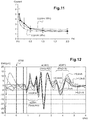
- the Figure 11 illustrates, in the context of such an application, a modeling of the law of Lapicque for a given target of reduction of the heart rate.
- the HR heart rate is under the control of the autonomic nervous system, the sympathetic system acting by increasing the heart rate and the parasympathetic system (which belongs to the vagus nerve) acting by slowing the heart rate.
- the expected physiological response must therefore be quantified, for example a 20% decrease in heart rate, this expected response constituting a target of heart rate that can be modeled, as illustrated in FIG. Figure 11 as a characteristic (pulse width, current) of the law of Lapicque LL.
- a target of heart rate that can be modeled, as illustrated in FIG. Figure 11 as a characteristic (pulse width, current) of the law of Lapicque LL.
- the decrease in heart rate will be greater than 20%, while for a point below this curve, this decrease will be less than 20%.
- This limit defines a target physiological criterion.
- the Lapicque curve LL ' will be located in a lower region of the space ⁇ pulse width, current ⁇ .
- a second clinical application is that of the controlled activation of a nerve fiber.
- a nerve consists of several thousand axons, the vagus nerve thus comprising more than 100,000 fibers.
- These fibers have varying diameters (ranging from 25 microns to 0.2 microns for the smallest), and may or may not be myelinated. They all lead to action potentials, but the conduction velocity depends on their diameter (the larger fibers drive the action potentials faster) and whether or not they are myelinated (the myelinated fibers lead faster to action potentials).
- their stimulation threshold also depends on these same parameters (the larger fibers and the myelinated fibers have lower activation thresholds, that is to say they are more easily excitable).
- eCAP evoked Compound Action Potential
- the fastest (largest) fibers will produce action potentials at the beginning of the eCAP, while the slower fibers (the smaller ones) will produce action potentials at the end of the eCAP.
- the activation threshold of a fiber in terms of electrical charge, depends on its diameter (the smaller the diameter is the activation threshold, and vice versa ), the lower the level of activation. more stimulus increases the activated fibers will be numerous, so that the eCAP will increase in amplitude for the same type of fiber and in duration for fibers of different characteristics.
- the Figure 12 thus shows an example of an electroneurogram ENG illustrating the modifications of the composite evoked action potential for different stimulus levels corresponding to currents between 0.2 and 1.5 mA. So, on the Figure 12 Several components of eCAP are observable, the A ⁇ , A ⁇ and B fibers (from the fastest to the slowest) appearing more or less close to nerve stimulation.
- nerve activation can be represented by a Lapicque curve, for a quantified target value.
- the target value is expressed as a percentage of a component of the eCAP in relation to its maximum value.
- the maximum value will be that measured by a system for collecting the ENG. In another implementation, it will be a typical predefined value. For example, for B fibers, if the measured maximum is 20 ⁇ V peak-to-peak, a target of 20% will correspond to a fiber eCAP equal to 4 ⁇ V. Likewise for a typical value of 15 ⁇ V, a target of 20% will correspond to a target of 3 ⁇ V.
- the Figure 13 illustrates two examples of Lapicque characteristics LL 20 and LL 40 , respectively for values of 20% and 40% of the maximum activation value of a defined potential. These values are given by way of example, different values could be used in specific cases.
- intersection X1, X2 or X3 of these two curves corresponds to a "pivot point" which must be determined to adjust the characteristics of the compensating phase, in particular of the precharge pulse, as explained above in relation to the Figure 9 .
- the Figure 15 illustrates the general flowchart of the main stages of implementation of the test for determining the charge of the compensating phase C pc as a function of the applied stimulation charge C ap (whose current and pulse length parameters are predetermined, whether fixed by the doctor or calculated by a specific algorithm).
- the next step (block 102) is to set a given level of compensating load, which can be a level equal to the load of the pulse of stimulation or that may also depend on other parameters such as heart rate, electrode configuration, etc.
- the next step (block 104) is to apply a test neurostimulation sequence by scanning the different possible values (pulse width, current) by repeated stimulations, with measurement in each case the physiological and / or physical parameter that can be influenced by the delivery of the pulse (block 106).
- the charge value that was set in step 102 is then adjusted if necessary at the end of the scan (block 108), the previous process then being reiterated.
- the system comprises only a system of bipolar or quasi-tripolar electrodes. In another implementation, it comprises several electrodes for stimulation on several dipoles or electrode configurations. The algorithm is then applied to each electrode system.
- the algorithm of the Figure 15 is automatically applied by the pacemaker without external intervention. In another embodiment, it is applied under the control of the physician, through the communication system, and makes it possible to set the values of the stimulation pulses and the compensating pulses. In another implementation, part of the functions are performed by the pacemaker and another part by the doctor through the communication system.
- the Figures 16 to 18 illustrate more precisely how the multiphase pulse trains of this test sequence are applied.
- the Figure 16 shows the application of two multiphasic neurostimulation pulse trains VNS delivered in synchronism with the EGM heart rate.
- the pulses can be delivered asynchronously to the parasympathetic structure but, preferably, they are delivered synchronously to the cardiac events, as illustrated in FIG. Figure 16 the neurostimulation pulse train is then delivered synchronously on the P or R wave, with a delay D between the detection of the P or R wave and the beginning of the neurostimulation pulse train.
- the complete TNSS test sequence comprises a succession of stimulus bursts (as illustrated in FIG. 17) applied to consecutive cardiac events, for example cardiac cycles No. 2 to No. 5, this test sequence being preceded (cycle no. 1) and followed (cycle 6) by cardiac cycles without neurostimulation.
- the Figure 19 illustrates a first technique of optimal point search, based on a dichotomous iteration algorithm
- Figure 20 illustrates a second technique, based on a pseudo-stochastic type algorithm (that is to say stochastic excluding points already tested).
- the abscissa of the point P i + 1 is determined to be 90% of the abscissa of the point Pi in the absence of expected physiological response (i.e., the point is below the curve Lapicque LL), the abscissa P i + 1 being such that the abscissa of Pi was 80% that of P i + 1 otherwise.
- the abscissa of the points are determined by a random draw, excluding the points already tested.
- the Figure 21 illustrates the different steps of another pivot point search algorithm, for a third technique implementing a "step-by-step" search.
- the content of steps 200 to 216 and their sequence are directly indicated in this figure.
- the Figure 22 illustrates the variations in heart rate induced by successive bursts of a test sequence.
- test sequence is applied one or more times, each sequence being preferably repeated a predetermined number of times, providing between each sequence.
- test TNSS a period of "purge" P allowing the return of the physiological parameter tested (in this figure, the RR intervals measuring the heart rate so as to avoid any cumulative effect between the successive test sequences).
- the Figures 23 to 25 illustrate a fourth technique , consisting, in a first step, in roughly determining on the curve (pulse width, current) a pivot zone framing the desired pivot point and, in a second step, seeking this pivot point by variations restricted to the area of the pivot zone.
- the Figure 23 illustrates the main steps of such an algorithm.
- the next step (block 302) consists in carrying out a first scanning test by traversing the pulse width / current curve with large pitches, for example steps of 3 to 3 of the index values of Table 1 presented above. .
- This quick scan is illustrated on the Figure 24 , where the points corresponding to index values 1, 4, 7, 10, 13, etc. of Table 1 have been indicated.
- This scanning can be carried out by one of the techniques described above (dichotomous, pseudo- stochastic, step by step), or any other method that converges to the pivot zone ZP).
- the first rough scan is thus performed with only twelve different values of torques (pulse width, current).
- the ZP pivot zone (block 304) is defined, for example from the highest configuration and from the lowest configuration. (in index number) not producing a change in the physiological response.
- the smallest configuration is that corresponding to the index No. 16 (no change of response between the points 13 and 16) and the highest is the configuration of the index No. 28 (no modification of the answer between point 28 and point 31).
- the process then continues (block 306) by implementing one of the previously described techniques (dichotomous, pseudo-stochastic, stepwise or other search), but restricted to the domain of the ZP pivot zone, as shown in FIG. Figure 25 .
- This search is performed with a fine pitch, an index unit, but only on a restricted range of Table 1.
- the pivot zone was bounded by indexes Nos. 16 and 28, so that the fine search will be performed only with torques (pulse width, current) between index n ° 17 and the index n ° 27.
- the Figure 26 is a general flowchart presenting the successive steps of searching for the optimal configuration, according to the variations of the physiological response according to the various configurations.
- the flowchart starts at step 300 for a configuration i .
- the data produced by the physiological and / or physiological parameter sensor (s) reflecting the physiological response are stored (block 302), with possibly selecting from among several data those which are the most representative of the physiological response at this stage.
- the data may optionally make a selection (block 306), for example by keeping only the last x cycles of the purge period and y last cycles of the stimulation period.
- the physiological response is then calculated (block 308), for example by determining an average or a median of the validated and selected data.
- the pulse width and the current of the compensating phase are determined (block 316), that is to say that an index of Table 1 is chosen, possibly with application of a margin the security of increasing this index by two units. For example, if the pulse width and current limit values are obtained for index # 5 (0.9 ms / 1.11 mA) corresponding to the data closest to the pivot point X, then the values actually applied for the width and current of the precharge pulse will be those corresponding to index No. 7 (1.1 ms / 0.91 mA).
- the selected parameters are automatically sent by the Home Monitoring at regular intervals.
- the parameters are sent only if they exceed certain limit values considered abnormal.
- several current generators are used. Each one potentially has its own stimulation profile, including stimulation and compensatory phases.
- each compensating phase of each generator is managed independently of the other phases and generators, on its parameters of duration and current.
- the compensating phases are managed proportionally to the charge injection of their stimulation phase. For example, if the compensating phases must be reduced by 1 ⁇ C, the compensating phase of a pole delivering 80% of the current will be reduced by 0.8 ⁇ C (current decrease and / or duration).
Landscapes
- Health & Medical Sciences (AREA)
- Life Sciences & Earth Sciences (AREA)
- Animal Behavior & Ethology (AREA)
- General Health & Medical Sciences (AREA)
- Veterinary Medicine (AREA)
- Engineering & Computer Science (AREA)
- Biomedical Technology (AREA)
- Public Health (AREA)
- Nuclear Medicine, Radiotherapy & Molecular Imaging (AREA)
- Radiology & Medical Imaging (AREA)
- Neurology (AREA)
- Neurosurgery (AREA)
- Heart & Thoracic Surgery (AREA)
- Biophysics (AREA)
- Cardiology (AREA)
- Physiology (AREA)
- Physics & Mathematics (AREA)
- Pathology (AREA)
- Medical Informatics (AREA)
- Molecular Biology (AREA)
- Surgery (AREA)
- Electrotherapy Devices (AREA)
Abstract
Ce dispositif (10) comprend un générateur (24) produisant des trains impulsionnels multiphasiques de neurostimulation, chaque train impulsionnel comprenant au moins une impulsion de stimulation précédée d'une impulsion de précharge et se terminant par une impulsion de décharge passive. Un capteur (16) délivre un signal de contrôle représentatif d'un paramètre physiologique et/ou physique susceptible d'être influencé par la délivrance des trains impulsionnels de neurostimulation. Un circuit de contrôle automatique de compensation de charge (24, 26, 28) reçoit en entrée le signal de contrôle délivré par le capteur, détermine une amplitude et/ou une durée d'impulsion de précharge en fonction d'au moins un critère prédéterminé, et délivre au générateur (24) un signal de pilotage des impulsions de précharge à produire en sortie.

Description
L'invention concerne les "
Elle concerne plus précisément les implants permettant de délivrer des thérapies dites FES (Functional Electrical Stimulation), consistant à appliquer à des fins thérapeutiques sur des organes une stimulation sous forme d'impulsions électriques répétées.It relates more specifically to implants for delivering so-called FES ( Functional Electrical Stimulation ) therapies, consisting in applying stimulation in the form of repeated electrical pulses for therapeutic purposes on organs.
L'invention concerne plus particulièrement les implants permettant de délivrer des thérapies de stimulation de tissus biologiques. L'invention porte plus précisément sur la stimulation du système nerveux (ci-après désignée de façon générale "neurostimulation"), notamment mais de façon non limitative de stimulation du nerf vague, technique dite "VNS" (Vagus Nerve Stimulation), au moyen d'un dispositif comprenant une sonde pourvue d'une électrode implantée sur le nerf vague ou à proximité de celui-ci, et un générateur délivrant des impulsions électriques VNS sur cette électrode.The invention relates more particularly to implants for delivering biological tissue stimulation therapies. The invention relates more specifically to the stimulation of the nervous system (hereinafter generally referred to as "neurostimulation"), in particular, but in a non-limiting manner, vagus nerve stimulation, the so-called "VNS" technique ( Vagus Nerve Stimulation ), by means of a device comprising a probe provided with an electrode implanted on the vagus nerve or in the vicinity thereof, and a generator delivering electrical pulses VNS on this electrode.
Le
Cette application n'est toutefois pas limitative, et l'invention est applicable à d'autres cas où une stimulation de tissus biologiques nécessite la délivrance d'impulsions de compensation.This application is however not limiting, and the invention is applicable to other cases where stimulation of biological tissues requires the delivery of compensation pulses.
La stimulation du système nerveux est une approche thérapeutique reconnue ou en cours d'évaluation à l'égard de très nombreux troubles tels que l'épilepsie, la dépression profonde, la douleur, l'insuffisance cardiaque, l'apnée du sommeil, l'obésité, etc. La VNS a démontré des effets positifs dans des études précliniques dans le cadre de l'insuffisance cardiaque, où elle agit sur le système nerveux autonomique et de façon secondaire sur les fonctions cardiovasculaires, induisant une diminution du rythme cardiaque et une augmentation de la fraction d'éjection du ventricule gauche, ce qui peut notamment contribuer à réduire l'évolution d'un remodelage cardiaque susceptible de mener à un état d'insuffisance cardiaque aggravée.Stimulation of the nervous system is a recognized or evaluated therapeutic approach to many disorders such as epilepsy, deep depression, pain, heart failure, sleep apnea, obesity, etc. VNS has demonstrated positive effects in preclinical studies in the context of heart failure, where it acts on the autonomic nervous system and secondary on cardiovascular functions, inducing a decrease in heart rate and an increase in the heart rate. ejection of the left ventricle, which may in particular contribute to reducing the progression of a cardiac remodeling likely to lead to a state of aggravated heart failure.
Par son action sur l'équilibre sympathovagal (SVB) du patient, la neurostimulation a également un effet général sur le système vasculaire, avec modulation de la vasoconstriction par modification des diamètres des artères et de la résistance périphérique se traduisant par une vasodilatation générale du système vasculaire.Through its action on the sympathovagal balance (SVB) of the patient, neurostimulation also has a general effect on the vascular system, with modulation of vasoconstriction by changes in arterial diameters and peripheral resistance resulting in general vasodilatation of the system. vascular.
Les impulsions de neurostimulation peuvent être délivrées de façon synchrone, ou non, avec le rythme cardiaque ou tout autre paramètre physiologique, auquel cas le dispositif comprend des moyens de recueil d'au moins un paramètre physiologique, typiquement des ondes de dépolarisation du myocarde, qui peuvent être mesurées par recueil d'un ECG par une électrode subcutanée, d'un EGM par une électrode implantée sur ou dans le myocarde, ou d'un signal far-field recueilli entre le boitier et une électrode placée en dehors du coeur, notamment un pôle de l'électrode de neurostimulation placée sur ou à proximité d'une structure nerveuse.The neurostimulation pulses can be delivered synchronously or not with the heart rate or any other physiological parameter, in which case the device comprises means for collecting at least one physiological parameter, typically myocardial depolarization waves, which can be measured by collecting an ECG by a subcutaneous electrode, an EGM by an electrode implanted on or in the myocardium, or a far-field signal collected between the housing and an electrode placed outside the heart, in particular a pole of the neurostimulation electrode placed on or near a nerve structure.
Les impulsions de neurostimulation étant des impulsions de courant, lorsque l'on stimule un tissu physiologique, l'interface entre l'électrode et le tissu doit rester globalement équilibrée en termes de charge électrique. Dans le cas d'impulsions en courant constant, la charge Q est définie comme le produit du courant I (en ampères ou milliampères (mA)) par la durée PW de l'impulsion (en secondes ou millisecondes) : Q = I x PW, et s'exprime donc en coulombs, ou plus généralement en microcoulombs (µC) en neurostimulation.Since neurostimulation pulses are current pulses, when stimulating a physiological tissue, the interface between the electrode and the tissue must remain globally balanced in terms of electrical charge. In the case of constant current pulses, the load Q is defined as the product of the current I (in amperes or milliamperes (mA)) by the PW duration of the pulse (in seconds or milliseconds): Q = I x PW , and is thus expressed in coulombs, or more generally in microcoulombs (μC) in neurostimulation.
Comme la délivrance de l'impulsion de neurostimulation proprement dite (ci-après "phase de stimulation") va produire, du fait du passage du courant, une création et une accumulation d'une charge au niveau du site de stimulation, cette charge devra être compensée ou annulée par une charge contraire (par circulation d'un courant dans le sens inverse de celui de la phase de stimulation), de manière à maintenir la neutralité électrique globale du tissu stimulé.As the delivery of the neurostimulation pulse proper (hereinafter "stimulation phase") will produce, due to the passage of the current, a creation and accumulation of a charge at the stimulation site, this charge will have to to be compensated for or canceled by a counter-charge (by circulation of a current in the opposite direction to that of the stimulation phase), so as to maintain the overall electrical neutrality of the stimulated tissue.
Le
La charge contraire de compensation (ci-après "phase compensatrice") peut intervenir :
- sous forme passive, par une décharge spontanée dans la bioimpédance formée par les tissus au niveau du site de stimulation, cette décharge (ci-après "décharge passive") ayant lieu postérieurement à l'application d'une impulsion de stimulation isolée, ou d'une salve d'impulsions de stimulation successives ; et/ou
- sous forme active, par une charge résultant d'une impulsion de courant générée par le stimulateur et appliquée au tissu avant ("précharge") ou après ("postcharge") une ou plusieurs impulsions de stimulation.
- in passive form, by a spontaneous discharge in the bioimpedance formed by the tissues at the stimulation site, this discharge (hereinafter "passive discharge") taking place after the application of an isolated stimulation pulse, or a salvo of successive stimulation impulses; and or
- in active form, by a charge resulting from a current pulse generated by the stimulator and applied to the tissue before ("precharging") or after ("afterloading") one or more stimulation pulses.
On appellera "train impulsionnel multiphasique" une telle combinaison de phases temporelles, comprenant i) une phase de stimulation et ii) une phase compensatrice comprenant au moins une précharge/postcharge active ou une décharge passive finale.Such a combination of time phases will be referred to as "multiphase pulse train", comprising i) a stimulation phase and ii) a compensating phase comprising at least one active precharge / afterload or final passive discharge.
Dans la suite, on parlera simplement d"'impulsion de précharge" pour désigner un type d'impulsion compensatrice contrôlée, mais ce terme ne préjuge pas un type particulier de séquence multiphasique d'impulsions, la phase compensatrice contrôlée pouvant être générée non seulement avant, mais également après une phase de stimulation, que celle-ci soit formée d'une impulsion de stimulation isolée ou bien d'une salve d'impulsions de stimulation se succédant à une cadence élevée.In the following, we will simply speak of "precharge pulse" to designate a type of controlled compensating pulse, but this term does not prejudge a particular type of multiphasic sequence of pulses, the controlled compensating phase can be generated not only before , but also after a stimulation phase, that it is formed of an isolated stimulation pulse or a burst of stimulation pulses succeeding each other at a high rate.
Par ailleurs, différents profils multiphasiques combinant impulsion de précharge et impulsion de stimulation peuvent être envisagés, par exemple avec une impulsion de précharge associée à chaque impulsion de stimulation, ou une impulsion de précharge associée à plusieurs impulsions successives de stimulation, etc., étant précisé que l'invention sera applicable à tout type de profil de stimulation combinant impulsion de précharge (ou de postcharge), impulsion(s) de stimulation et impulsion de décharge passive. L'invention est applicable à tout type de stimulation multiphasique mettant en oeuvre ces différentes phases temporelles de précharge ou postcharge, stimulation et décharge passive, notamment la neurostimulation. Dans la suite du document on fera référence à la précharge, mais l'invention peut être appliquée similairement à une postcharge.Moreover, different multiphasic profiles combining precharge pulse and stimulation pulse can be envisaged, for example with a precharge pulse associated with each stimulation pulse, or a precharge pulse associated with several successive stimulation pulses, etc., being specified. that the invention will be applicable to any type of stimulation profile combining preload pulse (or afterload), stimulation pulse (s) and passive discharge pulse. The invention is applicable to any type of multiphasic stimulation using these different temporal phases of preload or afterload, stimulation and passive discharge, including neurostimulation. In the rest of the document reference will be made to the preload, but the invention may be applied similarly to an afterload.
Dans tous les cas, la phase de précharge comprend l'application d'une impulsion de courant de sens contraire de celui de l'impulsion de stimulation, et d'amplitude et de durée contrôlées, afin de produire une charge totale -Q égale mais inversée par rapport à celle Q de la stimulation.In all cases, the precharging phase comprises the application of a current pulse in the opposite direction to that of the stimulation pulse, and of controlled amplitude and duration, to produce a total charge -Q equal but inverted with respect to that Q of the stimulation.
Pour éviter que la précharge ne produise des effets physiologiques, l'amplitude de l'impulsion de précharge est ajustée à un niveau beaucoup plus faible que celui d'une impulsion de stimulation, sa durée étant allongée pour que la quantité de charge correspondante (égale au produit de l'intensité par la durée de l'impulsion) soit du même ordre de grandeur que la charge de stimulation à compenser. Par exemple, une impulsion de stimulation de 3 mA/0,5 ms sera compensée par une impulsion de précharge de 0,5 mA/3 ms.To prevent the preload from producing physiological effects, the amplitude of the precharge pulse is adjusted to a much lower level than that of a stimulation pulse, its duration being lengthened so that the corresponding amount of charge (equal to the product of the intensity by the duration of the pulse) is of the same order of magnitude as the stimulation charge to be compensated. For example, a stimulation pulse of 3 mA / 0.5 ms will be compensated by a precharge pulse of 0.5 mA / 3 ms.
L'objectif visé par un stimulateur produisant de tels trains impulsionnels multiphasiques est d'obtenir les effets physiologiques attendus - par exemple une réduction du rythme cardiaque, une modification contrôlée de l'équilibre sympathovagal, etc. - en respectant un équilibre global des charges électriques à la fin du train impulsionnel. Cependant, seule la stimulation doit produire un effet physiologique, les phases compensatrices (précharge, postcharge, décharge passive) ne doivent pas être effectives physiologiquement.The goal of a pacemaker producing such multiphase pulse trains is to achieve the expected physiological effects - for example, a reduction in heart rate, a controlled change in sympathovagal balance, and so on. - by respecting an overall balance of the electrical charges at the end of the pulse train. However, only the stimulation must produce a physiological effect, the compensating phases (preload, afterload, passive discharge) must not be physiologically effective.
Le problème principal, dans ce cas, est de s'assurer que les phases compensatrices (précharge(s) et décharge passive) ne produisent pas d'effets physiologiques indésirables.The main problem, in this case, is to ensure that the compensating phases (precharging (s) and passive discharge) do not produce undesirable physiological effects.
Or les nerfs, en particulier le nerf vague qui est souvent la cible d'une thérapie de neurostimulation, sont composés d'un très grand nombre de fibres nerveuses de types différents (type A, B, C notamment pour le nerf vague), chaque type de fibre ayant ses propres caractéristiques de seuil d'activation et de vitesse de propagation de l'influx nerveux. Ainsi, les fibres les plus grosses ont un seuil d'activation bas et une vitesse de propagation élevée, tandis que les fibres les plus fines présentent des propriétés inverses.Nerves, in particular the vagus nerve, which is often the target of neurostimulation therapy, are composed of a very large number of different types of nerve fibers (type A, B, C especially for the vagus nerve), each fiber type with its own activation threshold and rate of nerve impulse propagation characteristics. Thus, the largest fibers have a low activation threshold and a high propagation speed, while the finest fibers have inverse properties.
Les phases compensatrices peuvent ainsi produire certains effets physiologiques du fait d'une capture de l'impulsion par certaines fibres nerveuses, potentiellement celles dont le seuil d'excitation est le plus bas. Il faut également tenir compte du fait que les fibres peu profondes, proches des électrodes, recevront plus de courant que les mêmes fibres situées en profondeur du nerf, et sont donc susceptibles d'être également activées même si leur seuil d'excitation est plus élevé.Compensatory phases can thus produce certain physiological effects due to the capture of the pulse by certain nerve fibers, potentially those whose excitation threshold is the lowest. It should also be taken into account that the shallow fibers, close to the electrodes, will receive more current than the same fibers located in depth of the nerve, and are therefore likely to be activated even if their excitation threshold is higher.
Un premier but de l'invention est donc d'assurer une capture lors des phases de stimulation des fibres que l'on souhaite activer, tout en évitant une telle capture lors des phases compensatrices.A first object of the invention is therefore to ensure capture during the stimulation phases of the fibers that one wishes to activate, while avoiding such capture during the compensating phases.
D'autres effets inattendus peuvent être observés sur des organes innervés par le nerf stimulé. Typiquement, on sait que le rythme cardiaque est ralenti par une stimulation du nerf vague, mais on constate qu'un ralentissement supplémentaire peut être produit par les fibres parasympathiques (fibres de type B) excitées par les phases compensatrices. Une stimulation multiphasique par des trains impulsionnels comportant des phases de stimulation et des phases compensatrices induit ainsi une réduction importante du rythme cardiaque, plus importante que celle que l'on aurait constatée avec une simple stimulation monophasique ne comportant pas de phases compensatrices.Other unexpected effects can be observed on organs innervated by the stimulated nerve. Typically, it is known that the heart rate is slowed by vagus nerve stimulation, but it is found that further slowing can be produced by the parasympathetic fibers (type B fibers) excited by the compensatory phases. A multiphase stimulation by pulse trains comprising stimulation phases and compensating phases thus induces a significant reduction in heart rate, greater than that which would have been observed with a simple monophasic stimulation having no compensating phases.
Un deuxième but de l'invention est donc de pouvoir évaluer et contrôler la réponse physiologique produite le cas échéant par les phases compensatrices.A second object of the invention is therefore to be able to evaluate and control the physiological response produced, if necessary, by the compensating phases.
Enfin, à chaque fois qu'une neurostimulation est appliquée par le générateur du dispositif, celui-ci entre dans une période réfractaire absolue pendant laquelle est opérée une déconnexion ou blanking des circuits de détection, notamment de l'activité cardiaque et de l'électroneurogramme, et c'est seulement à l'issue de cette période de blanking que les circuits de détection et de mesure des potentiels physiologiques sont réactivés.Finally, whenever a neurostimulation is applied by the generator of the device, it enters an absolute refractory period during which a disconnection or blanking of the detection circuits, in particular of the cardiac activity and of the electroneurogram, is effected. , and it is only at the end of this blanking period that the detection and measurement circuits of the physiological potentials are reactivated.
Un troisième but de l'invention est de permettre une réduction à un minimum de la durée des phases compensatrices (précharge, postcharge et décharge passive), de manière à réduire d'autant la durée de la période de blanking et permettre ainsi un retour rapide du dispositif à un fonctionnement normal, c'est-à-dire avec toutes les fonctions de détection des potentiels physiologiques. On notera toutefois que si l'on réduit la durée d'une impulsion de précharge, il faudra en augmenter d'autant l'amplitude pour conserver la même valeur de charge électrique, avec pour conséquence le risque d'induire des effets physiologiques qui ne seraient pas apparus avec une impulsion plus longue et de moindre amplitude.A third object of the invention is to allow a reduction to a minimum of the duration of the compensating phases (preload, afterload and passive discharge), so as to reduce the duration of the blanking period and thus allow a quick return the device to normal operation, that is to say with all the functions of detection of physiological potentials. It will be noted, however, that if the duration of a precharging pulse is reduced, it will be necessary to increase its amplitude by the same amount in order to maintain the same electrical charge value, with the consequent risk of inducing physiological effects that do not occur. would not have appeared with a longer pulse and less amplitude.
L'idée de base de l'invention consiste, pour atteindre les buts précités, à prévoir un circuit de détection d'un paramètre physiologique et/ou physique et à produire un train impulsionnel de test afin de discriminer et évaluer l'apparition d'un éventuel effet physiologique produit par les phases compensatrices, puis piloter le générateur de neurostimulation en fonction du résultat du test de manière à adapter les paramètres de la (des) phase(s) compensatrice(s) active(s), c'est-à-dire de la (des) impulsion(s) de précharge ou postcharge, ou encore de décharge passive.The basic idea of the invention consists, in order to achieve the aforementioned aims, of providing a circuit for detecting a physiological and / or physical parameter and producing a test pulse train in order to discriminate and evaluate the appearance of a possible physiological effect produced by the compensating phases, then control the neurostimulation generator according to the test result so as to adapt the parameters of the compensating phase (s) active (s), that is to say that is to say, the pulse (s) of precharging or after charging, or passive discharge.
Le paramètre physiologique et/ou physique peut être un paramètre d'activité électrique du coeur, par exemple le rythme cardiaque HR (Heart Rate) calculé à partir des intervalles RR d'un signal d'électrogramme endocavitaire EGM. Il peut s'agir également d'un paramètre d'activité électrique du système nerveux dérivé d'un signal d'électroneurogramme ENG, d'un paramètre de fréquence respiratoire (ventilation-minute MV), de courant électrique traversant un tissu, d'accélération du corps du patient (accélération G), de pression sanguine, d'accélération endocardiaque EA, etc. Dans une autre mise en oeuvre, la (les) phase(s) compensatrice(s) active(s) peu(ven)t être ajustée(s) sur le niveau de la décharge passive, afin d'équilibrer les charges.The physiological and / or physical parameter may be a parameter of electrical activity of the heart, e.g. HR heart rate calculated from the RR intervals of an endocaval EGM electrogram signal. It may also be a parameter of electrical activity of the nervous system derived from an ENG electronogram signal, a respiratory rate parameter (MV minute ventilation), an electrical current passing through a tissue, a acceleration of the patient's body (acceleration G), blood pressure, endocardial acceleration EA, etc. In another implementation, the active compensating phase (s) can be adjusted (s) to the level of the passive discharge, in order to balance the charges.
Selon le mode de réalisation mis en oeuvre et l'application particulière visée, le train impulsionnel multiphasique de test peut inclure, ou non, une ou plusieurs impulsions de stimulation. En d'autres termes, selon le cas, le test peut être effectué avec des impulsions de neurostimulation combinées à des impulsions de précharge, ou seulement avec des impulsions de précharge, sans neurostimulation.According to the embodiment implemented and the particular application aimed at, the multiphase test pulse train may or may not include one or more stimulation pulses. In other words, depending on the case, the test can be performed with neurostimulation pulses combined with precharge pulses, or only with precharge pulses, without neurostimulation.
Le principe de l'invention peut être appliqué soit à un système d'électrodes simples (notamment bipolaire, quasi-tripolaire ou tripolaire), mais aussi à un système combinant plusieurs électrodes de stimulation (notamment multipolaire). L'invention peut enfin s'appliquer à tout système de stimulation biologique délivrée en courant (notamment stimulation myo-cardique, musculaire).The principle of the invention can be applied either to a system of simple electrodes (in particular bipolar, quasi-tripolar or tripolar), but also to a system combining several stimulation electrodes (in particular multipolar). The invention can finally be applied to any biological stimulation system delivered in current (in particular myo-cardiac, muscular stimulation).
Plus précisément, l'invention a pour objet un dispositif médical actif comprenant, de manière en elle-même connue et divulguée notamment par le
- un générateur de neurostimulation électrique fonctionnelle, comprenant des moyens pour produire en sortie des trains impulsionnels multiphasiques de neurostimulation ;
- une sonde de stimulation, destinée à être disposée sur ou à proximité d'une structure du système nerveux d'un patient porteur du dispositif pour l'application à cette structure des trains impulsionnels de neurostimulation ;
- au moins un capteur délivrant un signal de contrôle représentatif d'un paramètre physiologique et/ou physique susceptible d'être influencé par la délivrance des trains impulsionnels de neurostimulation ; et
- un circuit de contrôle automatique de compensation de charge, comprenant des moyens pour recevoir en entrée le signal de contrôle délivré par le au moins un capteur.
- a functional electrical neurostimulation generator comprising means for outputting multiphasic neurostimulation pulse trains;
- a stimulation probe, intended to be placed on or near a structure of the nervous system of a patient carrying the device for the application to this structure of the neurostimulation pulse trains;
- at least one sensor delivering a control signal representative of a physiological and / or physical parameter that may be influenced by the delivery of the neurostimulation pulse trains; and
- an automatic charge compensation control circuit, comprising means for receiving as input the control signal delivered by the at least one sensor.
De façon caractéristique de l'invention, chaque train impulsionnel comprend au moins une impulsion de stimulation et au moins une impulsion compensatrice, cette dernière comprenant : une impulsion de précharge précédant l'impulsion de stimulation ; et/ou une impulsion de postcharge suivant l'impulsion de stimulation ; une impulsion de décharge passive terminant le train impulsionnel ; ou une combinaison des précédentes. Les impulsions de stimulation et compensatrice sont des impulsions de courant dont le sens, la durée et l'amplitude sont contrôlés, et les impulsions compensatrices procurent une charge électrique cumulée compensant la charge électrique de la au moins une impulsion de stimulation.In a characteristic manner of the invention, each pulse train comprises at least one stimulation pulse and at least one compensating pulse, the latter comprising: a precharge pulse preceding the stimulation pulse; and / or an afterload pulse following the stimulation pulse; a passive discharge pulse terminating the pulse train; or a combination of the previous ones. The pacing and compensating pulses are current pulses whose direction, duration, and amplitude are controlled, and the compensating pulses provide a cumulative electrical charge that compensates for the electrical charge of the at least one pacing pulse.
De plus, le circuit de contrôle automatique de compensation de charge comprend en outre des moyens pour déterminer une amplitude et/ou une durée d'impulsion compensatrice en fonction d'au moins un critère prédéterminé, et des moyens pour délivrer au générateur un signal de pilotage des impulsions compensatrices à produire en sortie par celui-ci.In addition, the automatic charge compensation control circuit further comprises means for determining an amplitude and / or a compensating pulse duration as a function of at least one predetermined criterion, and means for supplying the generator with a signal of controlling the compensating pulses to be output by the latter.
Selon diverses caractéristiques subsidiaires avantageuses :
- le circuit de contrôle automatique de compensation de charge est un circuit apte à : contrôler le générateur de manière à produire au moins un train impulsionnel de test ; recueillir le signal de contrôle après la fin du au moins un train impulsionnel de test ; déterminer d'après le niveau du signal de contrôle si un effet physiologique et/ou physique est ou non produit par l'application du train impulsionnel de test ; et déterminer l'amplitude et/ou la durée des impulsions compensatrices des trains impulsionnels suivants en fonction du résultat de la détermination ;
- le train impulsionnel de test comprend une impulsion de précharge suivie d'au moins une impulsion de stimulation ; dans ce cas, le circuit de contrôle automatique de compensation de charge est avantageusement apte à délivrer un unique train impulsionnel de test et à recueillir le signal de contrôle immédiatement après la fin du train impulsionnel de test ;
- en variante, le train impulsionnel de test comprend une impulsion de précharge mais ne comprend pas d'impulsion de stimulation ; dans ce cas, le circuit de contrôle automatique de compensation de charge est avantageusement apte à délivrer une pluralité de trains impulsionnels de test successifs et à recueillir le signal de contrôle après la fin du dernier train impulsionnel de test de ladite pluralité ;
- le circuit de contrôle automatique de compensation de charge est apte à déterminer l'amplitude et/ou la durée des impulsions compensatrices des trains impulsionnels courants en fonction de l'amplitude maximale de l'impulsion de décharge passive mesurée pour le train impulsionnel de test ;
- le circuit de contrôle automatique de compensation de charge est en outre apte à commander un intervalle temporel entre la fin de l'impulsion de stimulation et la fermeture d'interrupteurs de mise au même potentiel des électrodes de stimulation, de manière à moduler l'instant de début de l'impulsion de décharge passive ;
- le circuit de contrôle automatique de compensation de charge est en outre apte à commander un intervalle temporel entre la fin de l'impulsion de précharge et le début de l'impulsion de stimulation ;
- le circuit de contrôle automatique de compensation de charge est en outre apte à commander un intervalle temporel entre la fermeture et l'ouverture d'interrupteurs de mise au même potentiel des électrodes de stimulation, de manière à moduler la durée de l'impulsion de décharge passive ;
- le capteur est un capteur de mesure d'un paramètre du groupe formé par : activité électrique du coeur, activité électrique du système nerveux, rythme cardiaque, fréquence respiratoire, courant électrique traversant un tissu, accélération du corps du patient, pression sanguine, accélération endocardiaque, position du patient.
- the automatic charge compensation control circuit is a circuit able to: control the generator so as to produce at least one test pulse train; collecting the control signal after the end of the at least one test pulse train; determine from the level of the control signal whether or not a physiological and / or physical effect is produced by the application of the test pulse train; and determine the amplitude and / or the duration of the compensating pulses of the following pulse trains as a function of the result of the determination;
- the test pulse train comprises a precharge pulse followed by at least one stimulation pulse; in this case, the automatic charge compensation control circuit is advantageously capable of delivering a single test pulse train and of collecting the control signal immediately after the end of the test pulse train;
- alternatively, the test pulse train comprises a precharge pulse but does not include a stimulation pulse; in this case, the automatic charge compensation control circuit is advantageously able to deliver a plurality of successive test pulse trains and to collect the control signal after the end of the last test pulse train of said plurality;
- the automatic charge compensation control circuit is capable of determining the amplitude and / or the duration of the compensating pulses of the current pulse trains as a function of the maximum amplitude of the measured passive discharge pulse for the test pulse train;
- the automatic charge compensation control circuit is also able to control a time interval between the end of the stimulation pulse and the closing of equalization switches of the stimulation electrodes, so as to modulate the moment beginning of the passive discharge pulse;
- the automatic charge compensation control circuit is further adapted to control a time interval between the end of the precharge pulse and the start of the stimulation pulse;
- the automatic charge compensation control circuit is furthermore capable of controlling a time interval between the closing and opening of equalizing switches of the stimulation electrodes, so as to modulate the duration of the discharge pulse passive ;
- the sensor is a sensor for measuring a parameter of the group formed by: electrical activity of the heart, electrical activity of the nervous system, heart rate, respiratory rate, electrical current flowing through a tissue, acceleration of the patient's body, blood pressure, endocardial acceleration, patient position.
On va maintenant décrire un exemple de mise en oeuvre de la présente invention, en référence aux dessins annexés où les mêmes références désignent d'une figure à l'autre des éléments identiques ou fonctionnellement semblables.
- La
Figure 1 est une vue générale d'un patient implanté avec un dispositif VNS (stimulation du nerf vague), ce dispositif comprenant en outre des moyens de recueil du rythme cardiaque au moyen d'une sonde endocavitaire. - La
Figure 2 montre de façon schématique les principaux blocs fonctionnels du générateur du dispositif VNS de laFigure 1 pour la mise en oeuvre de l'invention. - La
Figure 3 illustre une séquence de délivrance de trains impulsionnels de thérapie VNS, synchronisés sur la détection des battements cardiaques. - La
Figure 4 illustre de façon plus précise un exemple de train impulsionnel de neurostimulation, avec les effets recherchés sur l'électroneurogramme ENG mais aussi les effets indésirables produits par chacune des impulsions de ce train impulsionnel. - La
Figure 5 illustre un exemple d'effet produit sur le rythme cardiaque par des trains impulsionnels de neurostimulation, respectivement avec et sans impulsion de précharge. - La
Figure 6 est une représentation d'une caractéristique "isocharge", pour trois valeurs de charge produites par une impulsion de courant en fonction de la durée PW de cette impulsion. - La
Figure 7 est un diagramme de Lapicque décrivant la relation entre les caractéristiques d'une impulsion de stimulation et une réponse physiologique résultante. - Les
Figures 8a et 8b sont des représentations schématiques des circuits équivalents du générateur d'impulsions (impulsions de stimulation ou bien de précharge) et de l'interface avec les tissus recevant ces impulsions, respectivement dans une phase d'application d'une impulsion et dans une phase de décharge passive. - La
Figure 9 est une représentation en superposition, caractéristique de l'invention, de l'allure d'une décharge passive avec un diagramme de Lapicque tel que celui de laFigure 7 . - Les
Figures 10a, 10b et 10c montrent trois exemples de train impulsionnel multiphasique avec, pour une même impulsion de stimulation, des impulsions de précharge d'amplitude ou de durée différentes, engendrant des impulsions de décharge passive de niveau différent. - La
Figure 11 illustre, dans le cadre d'une application de la technique de l'invention au contrôle du rythme cardiaque, une modélisation de la loi de Lapicque pour une cible donnée de réduction de la fréquence cardiaque. - La
Figure 12 illustre un neurogramme montrant les variations du potentiel d'action composite pour différentes valeurs du courant de stimulation. - La
Figure 13 illustre des caractéristiques selon la loi de Lapicque, correspondant à des cibles différentes de réduction de la fréquence cardiaque. - La
Figure 14 représente des caractéristiques isocharge déterminées pour différentes valeurs de charge produites par l'impulsion de décharge passive d'une phase compensatrice, en superposition avec une caractéristique selon la loi de Lapicque. - La
Figure 15 est un organigramme schématique des principales étapes de mise en oeuvre de la technique de l'invention. - La
Figure 16 illustre l'application de deux trains impulsionnels de neurostimulation délivrés en synchronisme avec le rythme cardiaque. - La
Figure 17 illustre l'application de trois modalités de VNS, d'un train impulsionnel multiphasique de neurostimulation ou d'une séquence de test où les trains impulsionnels appliqués présentent différents motifs de phases compensatrices. - La
Figure 18 illustre une séquence de test complète, délivrée en synchronisme avec le rythme cardiaque. - La
Figure 19 illustre, sur une superposition de la caractéristique isocharge et du diagramme de Lapicque, une technique de recherche du point optimal par un algorithme de type itératif. - La
Figure 20 est homologue de laFigure 19 , pour un algorithme de type pseudo-stochastique. - La
Figure 21 est un organigramme illustrant les principales étapes d'une technique de recherche du point optimal par un algorithme de type pas à pas. - La
Figure 22 illustre les variations du rythme cardiaque induites par des salves successives d'une séquence de test. - La
Figure 23 est un organigramme illustrant les principales étapes de recherche du point optimal par test de grandes, puis de petites, variations sur la courbe courant/largeur d'impulsion. - Les
Figures 24 illustrent, sur un diagramme courant/largeur d'impulsion, la technique de recherche de laet 25Figure 23 sur une caractéristique isocharge, respectivement pour des grandes variations et pour des petites variations sur cette courbe. - La
Figure 26 est un organigramme général présentant les étapes successives de recherche de la configuration optimale selon l'invention.
- The
Figure 1 is a general view of a patient implanted with a VNS device (vagus nerve stimulation), this device further comprising means for collecting the cardiac rhythm by means of an endocavity probe. - The
Figure 2 shows schematically the main functional blocks of the generator of the VNS device of theFigure 1 for the implementation of the invention. - The
Figure 3 illustrates a VNS pulse train delivery sequence, synchronized with the detection of heart beats. - The
Figure 4 illustrates more precisely an example of a neurostimulation pulse train, with the desired effects on the ENG electronogram but also the undesirable effects produced by each of the pulses of this pulse train. - The
Figure 5 illustrates an example of an effect produced on the heart rate by impulse neurostimulation trains, respectively with and without precharge pulse. - The
Figure 6 is a representation of an "isocharge" characteristic, for three charge values produced by a current pulse as a function of the PW duration of this pulse. - The
Figure 7 is a Lapicque diagram describing the relationship between the characteristics of a stimulation pulse and a resulting physiological response. - The
Figures 8a and 8b are diagrammatic representations of the equivalent circuits of the pulse generator (stimulation or preload pulses) and of the interface with the tissues receiving these pulses, respectively in a phase of applying a pulse and in a passive discharge phase. - The
Figure 9 is a representation in superposition, characteristic of the invention, the appearance of a passive discharge with a Lapicque diagram such as that of theFigure 7 . - The
Figures 10a, 10b and 10c show three examples of multiphasic pulse train with, for the same stimulation pulse, precharge pulses of different amplitude or duration, generating passive discharge pulses of different level. - The
Figure 11 illustrates, in the context of an application of the technique of the invention to the control of the cardiac rhythm, a modeling of the law of Lapicque for a given target of reduction of the heart rate. - The
Figure 12 illustrates a neurogram showing the variations of the composite action potential for different values of the stimulation current. - The
Figure 13 illustrates characteristics according to the law of Lapicque, corresponding to different targets of reduction of the heart rate. - The
Figure 14 represents isocharge characteristics determined for different charge values produced by the passive discharge pulse of a compensating phase, superimposed with a characteristic according to the law of Lapicque. - The
Figure 15 is a schematic flow diagram of the main stages of implementation of the technique of the invention. - The
Figure 16 illustrates the application of two neurostimulation pulse trains delivered in synchronism with the heart rhythm. - The
Figure 17 illustrates the application of three VNS modalities, a multiphasic neurostimulation pulse train or a test sequence where the applied pulse trains have different compensating phase patterns. - The
Figure 18 illustrates a complete test sequence, delivered in synchronism with the heart rhythm. - The
Figure 19 illustrates, on a superimposition of the isocharge characteristic and the Lapicque diagram, an optimal point search technique by an iterative algorithm. - The
Figure 20 is counterpart of theFigure 19 , for a pseudo-stochastic algorithm. - The
Figure 21 is a flowchart illustrating the main steps of an optimal point search technique using a step-by-step algorithm. - The
Figure 22 illustrates the variations in heart rate induced by successive bursts of a test sequence. - The
Figure 23 is a flow chart illustrating the main steps of finding the optimal point by testing large, then small, variations on the current curve / pulse width. - The
Figures 24 and 25 illustrate, on a current diagram / pulse width, the research technique of theFigure 23 on an isocharge characteristic, respectively for large variations and for small variations on this curve. - The
Figure 26 is a general flow chart showing the successive steps of searching for the optimal configuration according to the invention.
On va maintenant décrire un exemple de réalisation du dispositif de l'invention.An embodiment of the device of the invention will now be described.
En ce qui concerne ses aspects logiciels, l'invention peut être mise en oeuvre par une programmation appropriée du logiciel de commande d'un stimulateur connu, par exemple de type neurostimulateur, myostimulateur, stimulateur cardiaque, resynchroniseur et/ou défibrillateur, comprenant des moyens d'acquisition d'un signal fourni par des sondes endocavitaires et/ou un ou plusieurs capteurs implantés.With regard to its software aspects, the invention can be implemented by appropriate programming of the control software of a known stimulator, for example of the neurostimulator, myostimulator, pacemaker, resynchronizer and / or defibrillator type, comprising means acquisition of a signal provided by endocardial probes and / or one or more implanted sensors.
L'invention peut notamment être appliquée aux dispositifs implantables tels que ceux des familles Equilia, Repty et Paradym produits et commercialisés par Sorin CRM, Clamart, France.The invention can in particular be applied to implantable devices such as those of the Equilia, Repty and Paradym families produced and marketed by Sorin CRM, Clamart, France.
Il s'agit de dispositifs à microprocesseur programmable comportant des circuits pour recevoir, mettre en forme et traiter des signaux électriques recueillis par des électrodes implantées, et délivrer des impulsions de stimulation à ces électrodes. Il est possible d'y transmettre par télémétrie des logiciels qui seront conservés en mémoire et exécutés pour mettre en oeuvre les fonctions de l'invention qui seront décrites ci-dessous. L'adaptation de ces appareils à la mise en oeuvre des fonctions de l'invention est à la portée de l'homme du métier, et elle ne sera pas décrite en détail.These are programmable microprocessor devices having circuitry for receiving, shaping, and processing electrical signals collected by implanted electrodes, and providing pacing pulses to these electrodes. It is possible to transmit there by telemetry software which will be stored in memory and executed to implement the functions of the invention which will be described below. adaptation of these devices to the implementation of the functions of the invention is within the reach of the skilled person, and it will not be described in detail.
Le procédé de l'invention est mis en oeuvre par des moyens matériels et logiciels, au moyen d'algorithmes appropriés exécutés par un microcontrôleur ou un processeur numérique de signal et d'un circuit de stimulation en courant. Pour la clarté de l'exposé, les divers traitements appliqués seront décomposés et schématisés par un certain nombre de blocs fonctionnels distincts présentés sous forme de circuits interconnectés, mais cette représentation n'a toutefois qu'un caractère illustratif, ces circuits comprenant des éléments communs et correspondant en pratique à une pluralité de fonctions globalement exécutées par un même logiciel.The method of the invention is implemented by hardware and software means, by means of appropriate algorithms executed by a microcontroller or a digital signal processor and a current stimulation circuit. For the sake of clarity, the various treatments applied will be decomposed and schematized by a number of distinct functional blocks presented in the form of interconnected circuits, but this representation is however only illustrative, these circuits comprising common elements. and corresponding in practice to a plurality of functions globally executed by the same software.
Sur la
Dans d'autres mises en oeuvre, le signal détecté est un signal physiologique, notamment la ventilation-minute ou l'électroneurogramme. Dans une autre mise en oeuvre, la (les) phase(s) compensatrice(s) active(s) peut(vent) être ajustée(s) sur le niveau de la décharge passive, afin d'équilibrer les chargesIn other implementations, the detected signal is a physiological signal, in particular the minute ventilation or the electronogram. In another implementation, the active compensating phase (s) can (be) adjusted to the level of the passive discharge, in order to balance the loads.
De préférence, la stimulation VNS est appliquée au nerf vague droit au niveau cervical. Dans d'autres mises en oeuvre, la stimulation VNS est appliquée à gauche et/ou sur une branche du nerf vague. Dans d'autres mises en oeuvre encore, la neurostimulation est appliquée à proximité d'un nerf ou une de ses branches du système parasympathique.Preferably, the VNS stimulation is applied to the right vagus nerve at the cervical level. In other implementations, VNS stimulation is applied on the left and / or on a branch of the vagus nerve. In still other implementations, the neurostimulation is applied near a nerve or one of its branches of the parasympathetic system.
Le générateur 10 peut être éventuellement conçu pour délivrer, outre les impulsions de neurostimulation appliquées au nerf vague VN, des impulsions de cardiostimulation appliquées aux électrodes 18 (et éventuellement à d'autres électrodes, ventriculaires ou auriculaires) pour permettre le traitement de troubles bradycardiques, tachycardiques ou de de la synchronisation ventriculaire. Cette fonction n'est toutefois pas nécessaire pour la mise en oeuvre de l'invention, qui concerne seulement la thérapie de neurostimulation et l'analyse des effets de cette thérapie notamment (mais non nécessairement) à partir des signaux cardiaques recueillis par des électrodes endocardiaques, celles-ci pouvant être utilisées indifféremment en simples électrodes de détection de signal, ou bien en électrodes de détection/stimulation.The
L'ensemble peut être en outre muni d'un système de communication 20 comprenant un boitier externe de télémétrie permettant une communication avec le générateur 10 pour assurer le transfert et la réception de données avec ce dernier. Le boitier de communication peut être par ailleurs connecté à un dispositif externe tel qu'un programmateur ou bien un dispositif de home monitoring pour le suivi à distance du patient par télétransmission à un site distant des données recueillies et enregistrées par le générateur.The assembly may also be provided with a
On notera par ailleurs que, dans l'exemple illustré, la technique de l'invention se fonde principalement ou exclusivement sur l'analyse de signaux cardiaques (signaux EGM en l'espèce) pour l'analyse de l'effet physiologique de la neurostimulation et l'ajustement des paramètres de fonctionnement du générateur 10. Cette analyse peut toutefois, en variante ou en complément, se fonder sur des signaux produits par des capteurs relatifs à d'autres paramètres physiques ou physiologiques tels que : activité électrique du système nerveux (par analyse d'un électroneurogramme ENG), fréquence respiratoire (notamment le signal de ventilation-minute MV), courant électrique traversant un tissu, accélération du corps du patient (information donnée par un accéléromètre intégré au générateur implanté), pression sanguine, accélération endocardiaque EA (par un capteur d'accélération intégré à la sonde cardiaque 16), etc. De façon générale, il s'agit de disposer d'un signal représentatif d'au moins un paramètre physiologique ou physique susceptible d'être influencé par la délivrance des impulsions de stimulation, en l'espèce par la délivrance des impulsions VNS.Note also that, in the illustrated example, the technique of the invention relies mainly or exclusively on the analysis of cardiac signals (EGM signals in this case) for the analysis of the physiological effect of neurostimulation and the adjustment of the operating parameters of the
La
Le générateur 10 comprend un circuit 24 de production d'impulsions VNS, qui sont des impulsions de courant dont i) le sens, ii) l'amplitude du courant et iii) la durée (largeur d'impulsion PW) sont contrôlés en fonction de paramètres prédéterminés. Ces impulsions sont appliquées au nerf vague VN par la sonde 12, de la manière exposée plus haut.The
Dans une autre application, la configuration des pôles de stimulation peut être programmable, notamment dans un dispositif multipolaire disposant de plusieurs contacts électriques.In another application, the configuration of the stimulation poles can be programmable, in particular in a multipolar device having several electrical contacts.
Le générateur 10 comprend également un circuit 26 de recueil et de traitement de signaux physiologiques et/ou physiques, qui dans cet exemple sont des signaux d'activité électrique du coeur délivrés par une ou plusieurs électrodes de la sonde endocardiaque 16 (signaux d'électrogramme endocavitaire EGM) recueillis sur une ou plusieurs voies S1 ... Sn. Comme indiqué plus haut, ce circuit peut également recueillir d'autres signaux tels que : électroneurogramme ENG, accélération cardiaque EA, activité respiratoire (signal MV), accélération du corps du patient (signal G), niveau pic de la décharge passive, etc.The
Les circuits 24 et 26 sont interfacés à un contrôleur 28 et à une mémoire 30, pour permettre notamment le pilotage du circuit de neurostimulation 24, de la manière qui sera décrite plus bas, en fonction des signaux physiologiques et/ou physiques recueillis par le circuit 26.The
Le générateur peut également comprendre, comme indiqué plus haut, une interface de communication 32 pour l'échange de données avec des dispositifs extérieurs 20 tels qu'un programmateur pour permettre l'interaction avec un médecin à proximité du patient, et/ou un dispositif de home monitoring pour la télétransmission de données à un site distant où ces données seront analysées.The generator may also comprise, as indicated above, a
Le générateur 10 peut également comprendre un circuit 34 de détection de signaux d'activité nerveuse (électroneurogramme ENG), en particulier des signaux recueillis par les électrodes du manchon 14 en contact avec le nerf vague VN.The
Enfin, le générateur 10 peut être le cas échéant pourvu d'un circuit de cardiostimulation 36 apte à délivrer au coeur du patient, via la sonde endocavitaire 16, des impulsions de thérapie antibradycardique, antitachycardique et/ou de resynchronisation ventriculaire.Finally, the
On va maintenant expliquer, en référence aux
La
Typiquement, ces salves d'impulsion VNS sont délivrées pendant des périodes "ON" de durée prédéterminée, entrecoupées de périodes "OFF" pendant laquelle aucune stimulation VNS n'est délivrée. Ces salves de stimulation VNS, pilotées par le contrôleur 28, peuvent être définies par de nombreux paramètres de configuration tels que :
- synchronisme : la stimulation VNS peut être synchrone (comme dans le présent exemple) ou non des évènements cardiaques ;
- dans le cas d'une stimulation synchrone, ratio entre les stimulations VNS et les évènements cardiaques, un ratio de 1:1 indiquant une stimulation VNS à chaque évènement cardiaque détecté, un ratio de 1:4 indiquant une impulsion de stimulation VNS tous les quatre évènements cardiaques, etc. ;
- toujours dans le cas d'une stimulation VNS synchrone, durée de l'intervalle R-VNS, paramètre décrivant le retard entre la détection de l'évènement cardiaque et le début de la salve d'impulsions VNS, nombre d'impulsions VNS dans la salve ;
- courant délivré au nerf vague (courant pic ou courant moyen) ;
- fréquence des impulsions ;
- largeur des impulsions ;
- rapport cyclique (duty cycle) de l'alternance des périodes "ON" de stimulation et "OFF" de non-stimulation.
- synchronism: the VNS stimulation can be synchronous (as in the present example) or not cardiac events;
- in the case of synchronous stimulation, ratio between VNS stimulations and cardiac events, a ratio of 1: 1 indicating VNS stimulation at each detected cardiac event, a ratio of 1: 4 indicating a VNS stimulation pulse every four cardiac events, etc. ;
- always in the case of a synchronous VNS stimulation, duration of the interval R-VNS, parameter describing the delay between the detection of the cardiac event and the beginning of the pulse burst VNS, number of VNS pulses in the salvo;
- current delivered to the vagus nerve (peak current or average current);
- pulse frequency;
- pulse width;
- cyclic ratio ( duty cycle ) alternating periods "ON" stimulation and "OFF" non-stimulation.
Comme indiqué en introduction, l'invention concerne spécifiquement le cas où la stimulation est appliquée sous forme d'une succession de trains impulsionnels multiphasiques comprenant chacun :
- au moins une impulsion de précharge (et/ou de postcharge, ce cas étant assimilé à une impulsion de précharge), délivrée de façon contrôlée
par le générateur 24 ; - au moins une impulsion de neurostimulation proprement dite, également délivrée par le circuit de
neurostimulation 24 ; et - une impulsion apparaissant sous forme d'une décharge passive, spontanée, dans la bioimpédance formée par les tissus au niveau du site de stimulation.
- at least one precharge pulse (and / or afterload, which case is assimilated to a precharge pulse), delivered in a controlled manner by the
generator 24; - at least one neurostimulation pulse itself, also delivered by the
neurostimulation circuit 24; and - an impulse appearing as a passive, spontaneous discharge in the bioimpedance formed by the tissues at the site of stimulation.
L'impulsion de stimulation est délivrée sous forme d'un courant de sens prédéterminé et constitue une "phase de stimulation", tandis que les impulsions de précharge se présentent sous forme d'un courant de sens opposé, correspondant à une "phase compensatrice". La décharge passive est appliquée après les impulsions de précharge, de stimulation et de postcharge. Théoriquement, la charge électrique cumulée de la (des) phase(s) compensatrice(s) est égale, au signe près, à la charge électrique de l'impulsion de stimulation.The stimulation pulse is delivered in the form of a predetermined directional current and constitutes a "stimulation phase", while the precharging pulses are in the form of a current of opposite direction corresponding to a "compensating phase" . The passive discharge is applied after the precharge, stimulation and afterload pulses. Theoretically, the cumulative electric charge of the compensating phase (s) is equal, with the sign, to the electrical charge of the stimulation pulse.
La
Comme exposé en introduction, l'impulsion de précharge PC (qui peut être aussi une impulsion de postcharge produite après l'impulsion de stimulation ST) est une impulsion de sens (sens du courant délivré) contraire de celui de l'impulsion de neurostimulation ST, et délivre aux tissus une quantité de charge approximativement égale à celle de l'impulsion de stimulation ST, de façon à assurer la neutralité électrique finale et éviter une accumulation excessive de charges à l'interface de stimulation du nerf vague. À la fin du train impulsionnel, la décharge passive DP correspond à l'élimination des charges résiduelles encore éventuellement présentes au site de stimulation.As explained in the introduction, the PC precharge pulse (which may also be an afterload pulse produced after the ST stimulation pulse) is a sense pulse (direction of delivered current) opposite that of the ST neurostimulation pulse. and provides the tissues with an amount of charge approximately equal to that of the stimulating pulse ST, so as to ensure ultimate electrical neutrality and avoid excessive charge accumulation at the vagus nerve stimulation interface. At the end of the pulse train, the passive discharge DP corresponds to the elimination of residual charges still possibly present at the stimulation site.
La polarité de la décharge passive DP est a priori inconnue, car elle dépend des charges résiduelles à l'interface électrodes-tissus. Il faut considérer deux phénomènes : 1°) l'imprécision inhérente à tout système ne permet pas un équilibre parfait des charges délivrées, en valeur absolue, de l'impulsion de stimulation et des charges des précharges et post-charges, et 2°) certaines charges ont pu se dissiper dans le milieu ambiant.The polarity of the passive discharge DP is a priori unknown, because it depends on the residual charges at the electrode-tissue interface. Two phenomena must be considered: 1 °) the inherent inaccuracy of any system does not allow a perfect balance of the delivered loads, in absolute value, of the stimulation pulse and the charges of the preloads and post-charges, and 2 °) some charges have been dissipated in the environment.
En (b) et (c) des relevés d'électroneurogramme ENG montrent :
- les effets recherchés NR sur le système nerveux, ces effets résultant de l'impulsion de stimulation proprement dite ST, visibles en b),
- mais également, comme on peut le voir en (c), les effets indésirables NR' et/ou NR" produits respectivement par les impulsions de précharge PC et par la décharge passive DP.
- the effects sought NR on the nervous system, these effects resulting from the stimulation pulse itself ST, visible in b),
- but also, as can be seen in (c), the undesirable effects NR 'and / or NR "produced respectively by the PC precharge pulses and by the passive discharge DP.
Le but de l'invention est de proposer une technique permettant de contrôler ces réponses non attendues NR' et NR", généralement pour tenter de les faire disparaitre par un paramétrage approprié des impulsions de précharge PC.The object of the invention is to propose a technique for controlling these unexpected responses NR 'and NR ", generally to try to make them disappear by an appropriate parameterization of the PC precharge pulses.
Dans une variante, au lieu de chercher à réduire ou éliminer ces réponses non attendues, on cherchera à contrôler ces réponses sur le système nerveux produites par la phase compensatrice de la neurostimulation, de manière à maitriser la réponse globale produite à la fois par les impulsions de précharge PC et les impulsions de stimulation ST.Alternatively, instead of seeking to reduce or eliminate these unexpected responses, attempts will be made to control these responses on the nervous system produced by the compensatory phase of the neurostimulation, so as to control the overall response produced by both pulses. PC precharge and ST pacing pulses.
La
Le second chronogramme montre que les impulsions de précharge produisent une réduction additionnelle du rythme cardiaque HR (c'est-à-dire un allongement du délai RR entre deux cycles cardiaques successifs, par rapport à un train impulsionnel sans impulsion de précharge).The second timing chart shows that the precharging pulses produce an additional reduction in the HR heart rate (ie an increase in the RR delay between two successive cardiac cycles, compared to a pulse train without a precharge pulse).
Ce phénomène est dû à la capture de fibres parasympathiques, notamment les fibres de type A et/ou B du nerf vague, agissant sur la fréquence cardiaque par les phases compensatrices. Dans ce cas, l'utilisation d'impulsions compensatrices de précharge a pour effet une amplification de l'effet physiologique produit par la neurostimulation, phénomène dont il faudra tenir compte pour l'ajustement des paramètres de la neurostimulation.This phenomenon is due to the capture of parasympathetic fibers, notably the fibers of type A and / or B of the vagus nerve, acting on the heart rate by the compensating phases. In this case, the use of precharge compensating pulses has the effect of amplifying the physiological effect produced by the neurostimulation, a phenomenon which must be taken into account for the adjustment of the parameters of the neurostimulation.
La
Ainsi, une impulsion de stimulation de 1 ms/1 mA, soit 1 µC, pourra être compensée par une impulsion de précharge de 2 ms/0,5 mA, ou de 3 ms/0,33 mA, ou de 4 ms/0,25 mA, ou de 5 ms/0,20 mA, ou de 6 ms/0,17 mA, etc. On cherche bien entendu, pour minimiser les effets ou annuler les effets physiologiques produits par l'impulsion de précharge, à allonger celle-ci à une valeur de durée d'impulsion permettant de réduire d'autant l'amplitude du courant compensateur, et donc les effets physiologiques imprévus attachés à cette impulsion.Thus, a stimulation pulse of 1 ms / 1 mA,
La
Lorsque la réponse physiologique est un paramètre cardiaque tel que la fréquence cardiaque HR, la réponse physiologique est du type "tout ou rien", c'est-à-dire que, selon le cas, l'impulsion produit soit une dépolarisation complète du coeur (zone de capture ZC), soit une absence complète de dépolarisation (zone de non-capture ZNC). La frontière entre les deux zones ZC et ZNC, c'est-à-dire la limite inférieure de la zone de capture ZC, est la caractéristique LL dite "loi de Lapicque".When the physiological response is a cardiac parameter such as the HR heart rate, the physiological response is of the "all or nothing" type, that is to say that, as the case may be, the pulse produced is a complete depolarization of the heart (capture zone ZC), ie a complete absence of depolarization (non-capture zone ZNC). The boundary between the two zones ZC and ZNC, that is to say the lower limit of the capture zone ZC, is the LL characteristic known as "Lapicque law".
Cette courbe de Lapicque est typiquement caractérisée par deux descripteurs, à savoir :
- en ordonnée, le courant dit "rhéobase" RHB, qui est le niveau de courant auquel aucune capture ne sera jamais possible quelle que soit la largeur des impulsions (asymptote horizontale de la courbe LL) ; et
- en abscisse, une durée dite "chronaxie", CHX qui est la durée d'impulsion correspondant, par convention, au double de la rhéobase RHB.
- on the ordinate, the current called "rheobase" RHB, which is the current level at which no capture will ever be possible regardless of the width of the pulses (horizontal asymptote of the curve LL); and
- on the abscissa, a duration called "chronaxie", CHX which is the pulse duration corresponding, by convention, to twice the rheobase RHB.
Les
Dans une phase d'application d'une impulsion (
Lors de la décharge passive (
Le point de départ de l'invention réside dans une superposition d'une courbe isocharge (comme en
La
Un second aspect de l'invention consiste à prendre en compte les effets d'une décharge passive sur les tissus en superposant une courbe de Lapicque et une courbe de décharge passive, courbes qui ont les mêmes grandeurs en abscisse et en ordonnée, à savoir la largeur d'impulsion PW et l'intensité du courant.A second aspect of the invention consists in taking into account the effects of a passive discharge on the tissues by superimposing a Lapicque curve and a passive discharge curve, which curves have the same characteristics. in abscissa and ordinate, namely pulse width PW and current intensity.
La
Dans l'exemple illustré, la courbe DCH correspondant à une décharge passive se trouve toujours au-dessus de l'aire correspondant à l'impulsion {PWp, Ip}, ce qui signifie que les effets biologiques de la décharge passive seront toujours au moins aussi importants que les effets biologiques de l'impulsion. De plus, le point ST correspondant à l'impulsion {PWp, Ip} se situe nettement au-dessus de la courbe correspondant à la loi de Lapicque LL, ce qui signifie que cette impulsion produira effectivement une stimulation (le point ST étant situé dans la zone de capture ZC). On peut donc conclure, dans cet exemple, que la décharge passive, par rapport à la courbe de Lapicque LL, produira également un effet physiologique de stimulation.In the illustrated example, the DCH curve corresponding to a passive discharge is always located above the area corresponding to the pulse PW {p, I p}, which means that the biological effects of passive discharge will always at least as important as the biological effects of the impulse. In addition, the point ST corresponding to the pulse {PW p , I p } is well above the curve corresponding to the LL law, which means that this pulse will actually produce a stimulation (the point ST being located in the capture zone ZC). It can therefore be concluded in this example that the passive discharge, with respect to the Lapicque LL curve, will also produce a physiological stimulating effect.
La zone hachurée Z1 indique une zone qui devra être nécessairement évitée par la décharge passive, car cette dernière sera susceptible d'exciter des fibres nerveuses et donc de produire un effet physiologique indésirable.The shaded area Z1 indicates an area which must necessarily be avoided by the passive discharge, since the latter will be able to excite nerve fibers and thus produce an undesirable physiological effect.
Le but de l'invention est de proposer une technique permettant d'ajuster les caractéristiques de l'impulsion de précharge (ou postcharge) de manière à contrôler le niveau maximal de l'impulsion de décharge passive, typiquement pour minimiser celle-ci en deçà du seuil de stimulation, voire même la faire pratiquement disparaitre, par un équilibrage optimal de la quantité de charge de l'impulsion de précharge par rapport à l'impulsion de stimulation.The object of the invention is to propose a technique making it possible to adjust the characteristics of the precharge (or afterload) pulse so as to control the maximum level of the passive discharge pulse, typically to minimize it below this point. the stimulation threshold, or even make it practically disappear, by an optimal balancing of the amount of charge of the precharge pulse with respect to the stimulation pulse.
Les
Sur les trois figures, l'impulsion de stimulation ST est une impulsion de 0,5 mA/300 µs.In all three figures, the stimulation pulse ST is a pulse of 0.5 mA / 300 μs.
Sur la
On constate dans ce cas l'apparition d'une décharge passive DP pour laquelle le front initial produit un pic de courant d'environ -110 µA, soit plus du double de la valeur du courant de précharge (-50 µA). Cette impulsion de décharge passive va donc très vraisemblablement produire un effet physiologique indésirable.In this case, the occurrence of a passive discharge DP for which the initial edge produces a current peak of approximately -110 μA, is more than twice the value of the precharge current (-50 μA). This passive discharge pulse is therefore very likely to produce an undesirable physiological effect.
Or cette décharge est une décharge capacitive passive, non contrôlée en soi, qui ne dépend en fait que du niveau des charges appliquées à l'interface avec le nerf, de la bioimpédance de celui-ci, etc.However, this discharge is a passive capacitive discharge, not controlled in itself, which depends in fact only on the level of the charges applied to the interface with the nerve, the bioimpedance thereof, etc.
L'idée de base de l'invention consiste à moduler l'amplitude et/ou la durée de l'impulsion de précharge PC, donc la valeur de la charge appliquée préalablement à la stimulation, de manière à agir indirectement sur le niveau du pic de courant de la décharge passive DP, dès lors que l'on constate que la précharge appliquée a un effet sur le niveau de l'impulsion de décharge passive DP.The basic idea of the invention is to modulate the amplitude and / or the duration of the PC precharge pulse, therefore the value of the charge applied prior to the stimulation, so as to act indirectly on the peak level. current of the passive discharge DP, since it is found that the applied preload has an effect on the level of the passive discharge pulse DP.
Ainsi, sur la
Ainsi, en modulant l'impulsion de précharge PC, on peut arriver à maitriser la décharge passive DP pour amener celle-ci à un niveau auquel elle ne produira pas d'effets physiologiques indésirables, ou des effets négligeables.Thus, by modulating the PC precharge pulse, the passive discharge DP can be mastered to bring it to a level at which it will not produce undesirable physiological effects, or negligible effects.
D'autres séquencements de l'impulsion de précharge PC peuvent être envisagés pour réduire l'amplitude de la décharge passive DP, en modulant par exemple :
- le séquencement entre la fin de l'impulsion de précharge PC et le début de l'impulsion de stimulation ST ;
- le séquencement entre la fin de l'impulsion de stimulation ST et le début de l'impulsion de décharge passive DP (cet instant est en effet contrôlable, car il correspond à la fermeture des interrupteurs de mise au même potentiel électrique des électrodes de stimulation) ;
- le séquencement entre le début et la fin de l'impulsion de décharge passive DP (intervalle entre la fermeture et l'ouverture des interrupteurs de mise au même potentiel électrique).
- sequencing between the end of the PC precharge pulse and the start of the ST pacing pulse;
- the sequencing between the end of the stimulation pulse ST and the beginning of the passive discharge pulse DP (this instant is in fact controllable because it corresponds to the closing of the switching switches at the same electrical potential of the stimulation electrodes) ;
- the sequencing between the beginning and the end of the passive discharge pulse DP (interval between the closing and opening of the setting switches at the same electrical potential).
Comme illustré dans l'exemple de la
On va maintenant décrire, en référence aux
Une première application clinique est le contrôle du rythme cardiaque.A first clinical application is the control of the heart rhythm.
La
En augmentant la charge de l'impulsion de neurostimulation délivrée au nerf vague (courant et largeur d'impulsion), il est possible d'agir sur les variations de la fréquence cardiaque HR par un choix approprié de paramètres de VNS (notamment courant et largeur d'impulsion). Toutefois, à la différence de la stimulation cardiaque directe, c'est-à-dire d'une application d'impulsions de dépolarisation à des électrodes endocavitaires, les effets sur la diminution de la fréquence cardiaque HR dans le cas d'une neurostimulation sont des effets progressifs, de sorte que dans ce cas la loi de Lapicque ne suit pas un modèle de type "tout ou rien" tel qu'il avait été décrit plus haut, notamment en référence à la
La réponse physiologique attendue doit donc être quantifiée, par exemple une diminution de 20% de la fréquence cardiaque, cette réponse attendue constituant une cible de fréquence cardiaque qui est modélisable, comme illustré en
Pour une cible moindre, par exemple 10 % de diminution de la fréquence cardiaque, la courbe de Lapicque LL' sera située dans une région plus basse de l'espace {largeur d'impulsion, courant}.For a lesser target, for example 10% decrease in heart rate, the Lapicque curve LL 'will be located in a lower region of the space {pulse width, current}.
Une deuxième application clinique, illustrée en référence aux
Comme on l'a indiqué en introduction, un nerf est constitué de plusieurs milliers d'axones, le nerf vague comprenant ainsi plus de 100 000 fibres. Ces fibres présentent des diamètres variables (allant de 25 µm à 0,2 µm pour les plus petites), et peuvent être ou non myélinisées. Elles conduisent toutes des potentiels d'actions, mais la vitesse de conduction dépend de leur diamètre (les plus grosses fibres conduisent plus vite les potentiels d'action) et du fait qu'elles sont ou non myélinisées (les fibres myélinisées conduisent plus vite les potentiels d'action). De plus, leur seuil de stimulation dépend également de ces mêmes paramètres (les plus grosses fibres et les fibres myélinisées ont des seuils d'activation plus bas, c'est-à-dire sont plus facilement excitables).As mentioned in the introduction, a nerve consists of several thousand axons, the vagus nerve thus comprising more than 100,000 fibers. These fibers have varying diameters (ranging from 25 microns to 0.2 microns for the smallest), and may or may not be myelinated. They all lead to action potentials, but the conduction velocity depends on their diameter (the larger fibers drive the action potentials faster) and whether or not they are myelinated (the myelinated fibers lead faster to action potentials). Moreover, their stimulation threshold also depends on these same parameters (the larger fibers and the myelinated fibers have lower activation thresholds, that is to say they are more easily excitable).
Si l'on délivre au nerf un stimulus électrique d'un niveau suffisant, celui-ci produira un potentiel d'action évoqué composite ou eCAP (evoked Compound Action Potential), qui est la somme spatiale de tous les potentiels d'action produits par les fibres excitées par le stimulus. Compte tenu de la diversité des fibres, les fibres les plus rapides (les plus grosses) produiront des potentiels d'action dès le début du eCAP, tandis que les fibres les plus lentes (celles de petit diamètre) produiront des potentiels d'action en fin de eCAP. De plus, dans la mesure où le seuil d'activation d'une fibre, en termes de charge électrique, dépend de son diamètre (plus grand est le diamètre plus faible est le seuil d'activation, et vice versa), plus le niveau du stimulus augmente plus les fibres activées seront nombreuses, de sorte que le eCAP augmentera, en amplitude pour un même type de fibres et en durée pour des fibres de caractéristiques différentes.If one delivers an electrical stimulus to the nerve to a sufficient level, it will produce a composite action or evoked potential eCAP (evoked Compound Action Potential), which is the spatial sum of all action potentials produced by the fibers excited by the stimulus. Considering the In terms of fiber diversity, the fastest (largest) fibers will produce action potentials at the beginning of the eCAP, while the slower fibers (the smaller ones) will produce action potentials at the end of the eCAP. In addition, since the activation threshold of a fiber, in terms of electrical charge, depends on its diameter (the smaller the diameter is the activation threshold, and vice versa ), the lower the level of activation. more stimulus increases the activated fibers will be numerous, so that the eCAP will increase in amplitude for the same type of fiber and in duration for fibers of different characteristics.
La
Comme dans le cas du contrôle du rythme cardiaque, l'activation d'un nerf (eCAP) peut être représentée par une courbe de Lapicque, pour une valeur cible quantifiée. Dans ce cas, la valeur cible est exprimée en pourcentage d'une composante du eCAP par rapport à sa valeur maximale. Dans une mise en oeuvre, la valeur maximale sera celle mesurée par un système de recueil de l'ENG. Dans une autre mise en oeuvre, il s'agira d'une valeur typique prédéfinie. Par exemple, pour les fibres B, si le maximum mesuré est 20µV crête à crête, une cible de 20% correspondra à un eCAP de fibres B égal à 4µV. De même pour une valeur typique de 15µV, une cible de 20% correspondra à une cible de 3µV.As in the case of heart rate control, nerve activation (eCAP) can be represented by a Lapicque curve, for a quantified target value. In this case, the target value is expressed as a percentage of a component of the eCAP in relation to its maximum value. In one implementation, the maximum value will be that measured by a system for collecting the ENG. In another implementation, it will be a typical predefined value. For example, for B fibers, if the measured maximum is 20μV peak-to-peak, a target of 20% will correspond to a fiber eCAP equal to 4μV. Likewise for a typical value of 15μV, a target of 20% will correspond to a target of 3μV.
Ainsi, la
On va maintenant décrire plusieurs techniques algorithmiques permettant, selon l'invention, de déterminer les paramètres d'amplitude et/ou de durée de l'impulsion de précharge produite par le générateur du dispositif implanté, pour minimiser voire supprimer les effets secondaires indésirables produits par la phase compensatrice de la stimulation multiphasique.Several algorithmic techniques will now be described which make it possible, according to the invention, to determine the parameters of amplitude and / or duration the precharge pulse produced by the generator of the implanted device, to minimize or even eliminate the undesirable side effects produced by the compensatory phase of the multiphasic stimulation.
La
L'intersection X1, X2 ou X3 de ces deux courbes (isocharge et loi de Lapicque) correspond à un "point pivot" qu'il convient de déterminer pour ajuster les caractéristiques de la phase compensatrice, en particulier de l'impulsion de précharge, comme cela a été expliqué plus haut en relation avec la
La
La première étape (bloc 100) consiste à vérifier que les conditions initiales de mise en oeuvre de l'algorithme sont toutes vérifiées. Ces conditions peuvent être notamment :
- plage temporelle prédéterminée (par exemple une plage horaire choisie pour être toujours la même) ;
- patient au repos depuis un temps minimal prédéterminé (condition vérifiée à partir du signal produit par un capteur d'activité tel qu'un accéléromètre intégré au dispositif implanté) ;
- absence d'application d'une thérapie depuis un temps prédéterminé ;
- rythme cardiaque inférieur à la limite maximale ;
- rythme régulier, notamment absence de phase d'accélération ou de ralentissement des intervalles RR.
- predetermined time range (for example, a time slot chosen to always be the same);
- patient at rest for a predetermined minimum time (condition verified from the signal produced by an activity sensor such as an accelerometer integrated in the implanted device);
- failure to apply therapy for a predetermined time;
- heart rate below the maximum limit;
- regular rhythm, in particular absence of phase of acceleration or slowing down of RR intervals.
L'étape suivante (bloc 102) consiste à fixer un niveau donné de charge compensatrice, qui peut être un niveau égal à la charge de l'impulsion de stimulation ou bien qui peut également dépendre d'autres paramètres tels que le rythme cardiaque, la configuration d'électrodes, etc.The next step (block 102) is to set a given level of compensating load, which can be a level equal to the load of the pulse of stimulation or that may also depend on other parameters such as heart rate, electrode configuration, etc.
Le dispositif peut notamment déterminer, à partir du niveau de charge ainsi fixé, une série de couples de valeurs {largeur d'impulsion, courant} correspondant à cette valeur de charge. Par exemple, pour une charge prédéterminée Cpc = 1 µC, on définit le tableau suivant de valeurs de largeur d'impulsion avec leur niveau de courant associé.
L'étape suivante (bloc 104) consiste à appliquer une séquence de neurostimulation de test par un balayage des différentes valeurs possibles {largeur d'impulsion, courant} par des stimulations répétées, avec mesure dans chaque cas du paramètre physiologique et/ou physique susceptible d'être influencé par la délivrance de l'impulsion (bloc 106). La valeur de charge qui avait été établie à l'étape 102 est alors si besoin réajustée en fin de balayage (bloc 108), le processus précédent étant alors réitéré. Dans une mise en oeuvre, le système ne comporte qu'un système d'électrodes bipolaires ou quasi-tripolaires. Dans une autre mise en oeuvre, il comporte plusieurs électrodes permettant une stimulation sur plusieurs dipôles ou configurations d'électrodes. L'algorithme est alors appliqué à chaque système d'électrodes.The next step (block 104) is to apply a test neurostimulation sequence by scanning the different possible values (pulse width, current) by repeated stimulations, with measurement in each case the physiological and / or physical parameter that can be influenced by the delivery of the pulse (block 106). The charge value that was set in
Dans une mise en oeuvre, l'algorithme de la
Les
La
La
- en a), la séquence de test comprend un nombre prédéterminé d'impulsions de précharge PC associées à autant d'impulsions de stimulation ST. Par exemple, la séquence de test TNSS comprend quatre phases de stimulation précédées chacune d'une impulsion de précharge ;
- dans la variante illustrée en b), seules des impulsions de précharge sont appliquées dans la séquence de test TNSS ;
- dans une autre variante encore, illustrée en c), l'impulsion de stimulation est remplacée par une impulsion PC' identique à l'impulsion de précharge PC mais de polarité inversée, de manière à éviter à la fin de la séquence de test TNSS que des charges électriques ne s'accumulent à l'interface entre l'électrode et les tissus physiologiques.
- in a), the test sequence comprises a predetermined number of PC precharge pulses associated with as many ST pacing pulses. For example, the TNSS test sequence includes four stimulation phases each preceded by a precharge pulse;
- in the variant illustrated in b), only precharge pulses are applied in the TNSS test sequence;
- in yet another variant, illustrated in c), the stimulation pulse is replaced by a PC pulse 'identical to the PC precharge pulse but of inverted polarity, so as to avoid at the end of the TNSS test sequence that electrical charges do not accumulate at the interface between the electrode and the physiological tissues.
Comme illustré en
On va maintenant décrire, en référence aux
La
Il s'agit dans l'un ou l'autre cas d'évaluer la position du point pivot X avec le moins d'itérations possibles.In either case, it is a question of evaluating the position of the pivot point X with the least possible iterations.
Ces figures illustrent une superposition de la caractéristique isochrone Q avec le diagramme de la loi Lapicque LL, les ronds correspondent à des points situés au-dessous de la courbe de Lapicque LL, c'est-à-dire pour lesquels aucune réponse physiologique n'a été détectée, et les croix correspondent à des points situés au-dessus de cette même courbe, c'est-à-dire pour lesquels une réponse physiologique a été effectivement détectée.These figures illustrate a superposition of the isochronous Q characteristic with the Lapicque LL law diagram, the circles correspond to points situated below the Lapicque LL curve, that is to say for which no physiological response has been detected, and the crosses correspond to points situated above this same curve, that is to say for which a physiological response has actually been detected.
Les différentes itérations sont désignées, dans l'ordre, par P1, P2, P3... Dans l'algorithme dichotomique de la
La
La
Quelle que soit la technique mise en oeuvre, pour chaque couple de valeurs {largeur d'impulsion, courant}, la séquence de test est appliquée une ou plusieurs fois, chaque séquence étant de préférence répétée un nombre prédéterminé de fois en prévoyant entre chaque séquence de test TNSS une période de "purge" P permettant le retour du paramètre physiologique testé (sur cette figure, les intervalles RR mesurant le rythme cardiaque de manière à éviter tout effet cumulatif entre les séquences de test successives).Whatever the technique used, for each pair of values {pulse width, current}, the test sequence is applied one or more times, each sequence being preferably repeated a predetermined number of times, providing between each sequence. test TNSS a period of "purge" P allowing the return of the physiological parameter tested (in this figure, the RR intervals measuring the heart rate so as to avoid any cumulative effect between the successive test sequences).
Les
La
Celui-ci débute (bloc 300) par une détermination de l'instant optimal pour effectuer le balayage, en vérifiant que les conditions initiales sont toutes vérifiées (comme à l'étape 100 de la
L'étape suivante (bloc 302) consiste à effectuer un premier test de balayage en parcourant la courbe largeur d'impulsion/courant avec des pas grands, par exemple des pas de 3 en 3 des valeurs d'index du Tableau 1 présenté plus haut.The next step (block 302) consists in carrying out a first scanning test by traversing the pulse width / current curve with large pitches, for example steps of 3 to 3 of the index values of Table 1 presented above. .
Ce balayage rapide est illustré sur la
À partir des résultats obtenus (présence ou absence d'une réponse physiologique détectée pour chaque point de mesure), on définit la zone pivot ZP (bloc 304), par exemple à partir de la configuration la plus élevée et de la configuration la plus basse (en numéro d'index) ne produisant pas de changement de la réponse physiologique. Dans l'exemple illustré, la plus petite configuration est celle correspondant à l'index n° 16 (pas de changement de réponse entre les points 13 et 16) et la plus élevée est la configuration de l'index n° 28 (pas de modification de la réponse entre le point 28 et le point 31).From the results obtained (presence or absence of a physiological response detected for each measuring point), the ZP pivot zone (block 304) is defined, for example from the highest configuration and from the lowest configuration. (in index number) not producing a change in the physiological response. In the example shown, the smallest configuration is that corresponding to the index No. 16 (no change of response between the
Le processus se poursuit alors (bloc 306) par mise en oeuvre de l'une des techniques décrites précédemment (recherche dichotomique, pseudo-stochastique, pas à pas ou autre), mais restreinte au domaine de la zone pivot ZP, comme illustré sur la
Cette recherche est effectuée avec un pas fin, d'une unité index, mais seulement sur une plage restreinte du Tableau 1. Dans l'exemple illustré en
La
L'organigramme commence à l'étape 300, pour une configuration i.The flowchart starts at
Les données produites par le ou les capteurs du paramètre physiologique et/ou physique reflétant la réponse physiologique sont mémorisés (bloc 302), avec éventuellement sélection parmi plusieurs données de celles qui sont les plus représentatives de la réponse physiologique à ce stade.The data produced by the physiological and / or physiological parameter sensor (s) reflecting the physiological response are stored (block 302), with possibly selecting from among several data those which are the most representative of the physiological response at this stage.
Les données sont ensuite validées (bloc 304) de manière à exclure celles qui sont, par exemple, obtenues dans les cas suivants :
- au moins un cycle cardiaque accéléré, par exemple une augmentation du paramètre HR de plus de 25 % d'un battement à l'autre ;
- au moins un cycle cardiaque décéléré, par exemple où le paramètre HR a diminué de plus de 25 % d'un cycle suivant ;
- patient en activité, par exemple dans le cas où le capteur d'accélération indique un niveau accru, supérieur à un seuil prédéterminé ;
- expiration d'une durée autorisée, par exemple une heure donnée, pour l'exécution de l'algorithme.
- at least one accelerated cardiac cycle, for example an increase of the HR parameter by more than 25% from one beat to another;
- at least one decelerated cardiac cycle, for example where the HR parameter has decreased by more than 25% of a following cycle;
- active patient, for example in the case where the acceleration sensor indicates an increased level, greater than a predetermined threshold;
- expiration of an allowed time, for example a given time, for the execution of the algorithm.
Si les données sont validées, on peut éventuellement opérer une sélection (bloc 306), par exemple en ne conservant que les x derniers cycles de la période de purge et les y derniers cycles de la période de stimulation. La réponse physiologique est ensuite calculée (bloc 308), par exemple par détermination d'une moyenne ou d'une médiane des données validées et sélectionnées.If the data are validated, it may optionally make a selection (block 306), for example by keeping only the last x cycles of the purge period and y last cycles of the stimulation period. The physiological response is then calculated (block 308), for example by determining an average or a median of the validated and selected data.
Il est alors possible de déterminer (bloc 310) les variations de la réponse physiologique pour la configuration i en question.It is then possible to determine (block 310) the variations of the physiological response for the configuration i in question.
Si cette configuration n'est pas la dernière (bloc 312), la configuration i+1 suivante est sélectionnée (bloc 314) et l'algorithme des blocs 300 à 310 est réitéré pour cette nouvelle configuration.If this configuration is not the last (block 312), the next i +1 configuration is selected (block 314) and the
Une fois la dernière configuration atteinte, la largeur d'impulsion et le courant de la phase compensatrice sont déterminés (bloc 316), c'est-à-dire qu'un index du Tableau 1 est choisi, éventuellement avec application d'une marge de sécurité consistant à augmenter de deux unités cet index. Par exemple, si les valeurs de largeur d'impulsion et de courant limites sont obtenues pour l'index n° 5 (0,9 ms/1,11 mA) correspondant aux données les plus proches du point pivot X, alors les valeurs effectivement appliquées pour la largeur et le courant de l'impulsion de précharge seront celles correspondant à l'index n° 7 (1,1 ms/0,91 mA).Once the last configuration is reached, the pulse width and the current of the compensating phase are determined (block 316), that is to say that an index of Table 1 is chosen, possibly with application of a margin the security of increasing this index by two units. For example, if the pulse width and current limit values are obtained for index # 5 (0.9 ms / 1.11 mA) corresponding to the data closest to the pivot point X, then the values actually applied for the width and current of the precharge pulse will be those corresponding to index No. 7 (1.1 ms / 0.91 mA).
Dans une mise en oeuvre de l'invention, les paramètres sélectionnés sont automatiquement envoyés par le Home Monitoring à intervalles réguliers. Dans une autre mise en oeuvre, les paramètres ne sont envoyés que s'ils dépassent certaines valeurs limites considérées comme anormales. Dans le cas d'une configuration multipolaire, plusieurs générateurs de courant sont utilisés. Chacun a potentiellement son propre profil de stimulation, comprenant des phases de stimulation et compensatrices.In one implementation of the invention, the selected parameters are automatically sent by the Home Monitoring at regular intervals. In another implementation, the parameters are sent only if they exceed certain limit values considered abnormal. In the case of a multipolar configuration, several current generators are used. Each one potentially has its own stimulation profile, including stimulation and compensatory phases.
Dans une première mise en oeuvre, chaque phase compensatrice de chaque générateur est gérée indépendamment des autres phases et générateurs, sur ses paramètres de durée et de courant.In a first implementation, each compensating phase of each generator is managed independently of the other phases and generators, on its parameters of duration and current.
Dans une seconde mise en oeuvre, les phases compensatrices sont gérées proportionnellement à l'injection de charges de leur phase de stimulation. Par exemple, si les phases compensatrices doivent être diminuées de 1 µC, la phase compensatrice d'un pôle délivrant 80 % du courant sera réduite de 0,8 µC (diminution de courant et/ou de durée).In a second implementation, the compensating phases are managed proportionally to the charge injection of their stimulation phase. For example, if the compensating phases must be reduced by 1 μC, the compensating phase of a pole delivering 80% of the current will be reduced by 0.8 μC (current decrease and / or duration).
Claims (11)
et en ce que le circuit de contrôle automatique de compensation de charge (24, 26, 28) comprend en outre :
and in that the automatic load compensation control circuit (24, 26, 28) further comprises:
Applications Claiming Priority (1)
| Application Number | Priority Date | Filing Date | Title |
|---|---|---|---|
| FR1562184 | 2015-12-11 |
Publications (2)
| Publication Number | Publication Date |
|---|---|
| EP3187223A1 true EP3187223A1 (en) | 2017-07-05 |
| EP3187223B1 EP3187223B1 (en) | 2018-09-19 |
Family
ID=55300646
Family Applications (1)
| Application Number | Title | Priority Date | Filing Date |
|---|---|---|---|
| EP16202327.9A Active EP3187223B1 (en) | 2015-12-11 | 2016-12-06 | Active medical device for electric nerve stimulation, with automatic control of load compensation |
Country Status (3)
| Country | Link |
|---|---|
| US (1) | US10744327B2 (en) |
| EP (1) | EP3187223B1 (en) |
| WO (1) | WO2017097739A1 (en) |
Families Citing this family (3)
| Publication number | Priority date | Publication date | Assignee | Title |
|---|---|---|---|---|
| WO2019177798A1 (en) | 2018-03-12 | 2019-09-19 | Boston Scientific Neuromodulation Corporation | Neural stimulation with decomposition of evoked compound action potentials |
| CN109077711B (en) * | 2018-08-20 | 2021-08-10 | 深圳市元征科技股份有限公司 | Dynamic heart rate data acquisition method and device, wearable device and readable storage medium |
| CN112426623A (en) * | 2020-12-03 | 2021-03-02 | 浙江诺尔康神经电子科技股份有限公司 | Implanted nerve electrical stimulation asymmetric compensation system and method |
Citations (3)
| Publication number | Priority date | Publication date | Assignee | Title |
|---|---|---|---|---|
| US20090048643A1 (en) * | 2004-04-12 | 2009-02-19 | Erickson John H | Method for providing multiple voltage levels during pulse generation and implantable pulse generating employing the same |
| US20100114198A1 (en) | 2008-10-31 | 2010-05-06 | Medtronic, Inc. | Implantable medical device crosstalk evaluation and mitigation |
| EP2926863A1 (en) | 2014-04-01 | 2015-10-07 | Sorin CRM SAS | Use of an implantable cardiac generator for myocardial stimulation, defibrillation and/or resynchronisation as a vagus nerve stimulation (VNS) generator |
Family Cites Families (2)
| Publication number | Priority date | Publication date | Assignee | Title |
|---|---|---|---|---|
| US4373531A (en) * | 1979-04-16 | 1983-02-15 | Vitafin N.V. | Apparatus for physiological stimulation and detection of evoked response |
| US4821724A (en) * | 1986-08-01 | 1989-04-18 | Telectronics N.V. | Pacing pulse compensation |
-
2016
- 2016-12-06 EP EP16202327.9A patent/EP3187223B1/en active Active
- 2016-12-06 US US16/060,904 patent/US10744327B2/en active Active
- 2016-12-06 WO PCT/EP2016/079837 patent/WO2017097739A1/en active Application Filing
Patent Citations (3)
| Publication number | Priority date | Publication date | Assignee | Title |
|---|---|---|---|---|
| US20090048643A1 (en) * | 2004-04-12 | 2009-02-19 | Erickson John H | Method for providing multiple voltage levels during pulse generation and implantable pulse generating employing the same |
| US20100114198A1 (en) | 2008-10-31 | 2010-05-06 | Medtronic, Inc. | Implantable medical device crosstalk evaluation and mitigation |
| EP2926863A1 (en) | 2014-04-01 | 2015-10-07 | Sorin CRM SAS | Use of an implantable cardiac generator for myocardial stimulation, defibrillation and/or resynchronisation as a vagus nerve stimulation (VNS) generator |
Also Published As
| Publication number | Publication date |
|---|---|
| WO2017097739A1 (en) | 2017-06-15 |
| EP3187223B1 (en) | 2018-09-19 |
| US10744327B2 (en) | 2020-08-18 |
| US20180353760A1 (en) | 2018-12-13 |
Similar Documents
| Publication | Publication Date | Title |
|---|---|---|
| EP1857142B1 (en) | Active implantable medical device for cardiac stimulation, resynchronisation, cardioversion and/or defibrillation, comprising means for detecting ventricular noise artefacts | |
| EP2189182B1 (en) | Implantable active medical device comprising means for atrial capture testing | |
| EP2813260B1 (en) | Active implantable medical device for treating heart failure with stochastic stimulation of the vagus nerve | |
| US20100042176A1 (en) | Temporal-based cardiac capture threshold detection | |
| EP2646110A1 (en) | Adjusting cardiac pacing response sensing intervals | |
| EP3187223B1 (en) | Active medical device for electric nerve stimulation, with automatic control of load compensation | |
| EP2946806A1 (en) | Active implantable medical device with automatic optimisation of the configuration of a multi-electrode stimulation probe, in particular a probe for selective stimulation of the vagus nerve | |
| FR2808211A1 (en) | Heart implant stores cardiac activity intervals checks regular and sounds alarm | |
| EP2311524B1 (en) | Medical implantable cardiac pacemaker with automatic interventricular and atrioventricular intervals optimization | |
| EP2471575B1 (en) | Active implantable medical device with auricular stimulation for the treatment of diastolic cardiac insufficiency | |
| EP2926863B1 (en) | Use of an implantable cardiac generator for myocardial stimulation, defibrillation and/or resynchronisation as a vagus nerve stimulation (VNS) generator | |
| US8948867B2 (en) | Capture detection with cross chamber backup pacing | |
| US11730967B2 (en) | Systems and methods for improved his bundle and backup pacing timing | |
| US20110224751A1 (en) | Capture detection based on propagated depolarization from a pacing site | |
| EP2742973A1 (en) | Active implantable medical device such as a pacemaker with anodal stimulation detection by vector cardiogram analysis | |
| US7983752B2 (en) | Antitachycardiac stimulator | |
| EP3081257B1 (en) | Active implantable medical device for cardiac stimulation comprising means for detecting a remodelling or reverse remodelling phenomenon of the patient | |
| EP2803385B1 (en) | Implantable heart re-timer with biventricular stimulation and detection of losses of capture and anode stimulations | |
| EP3075413B1 (en) | Implantable medical device for biventricular stimulation, including means for measuring intraventricular conduction time for diagnosis of heart decompensation | |
| EP2873436B1 (en) | Active implantable medical device with bi-auricular stimulation for treating cardiac insufficiency with HFpEF preserved ejection fraction | |
| EP2881140B1 (en) | Active implantable medical device with dual chamber stimulation for treating cardiac insufficiency with HFpEF preserved ejection fraction | |
| US7620448B1 (en) | Methods and devices for monitoring myocardial mechanical stability | |
| EP2596832B1 (en) | Implantable cardioverter-defibrillator medical device with dynamically adjustable ventricular sensing threshold | |
| EP1080744A1 (en) | Implantable cardiac stimulator which automatically adjusts the level of stimulation pulses | |
| EP1543864A1 (en) | Multisite implantable active medical device comprising a resynchronisation mode of the ventricles |
Legal Events
| Date | Code | Title | Description |
|---|---|---|---|
| PUAI | Public reference made under article 153(3) epc to a published international application that has entered the european phase |
Free format text: ORIGINAL CODE: 0009012 |
|
| AK | Designated contracting states |
Kind code of ref document: A1 Designated state(s): AL AT BE BG CH CY CZ DE DK EE ES FI FR GB GR HR HU IE IS IT LI LT LU LV MC MK MT NL NO PL PT RO RS SE SI SK SM TR |
|
| AX | Request for extension of the european patent |
Extension state: BA ME |
|
| 17P | Request for examination filed |
Effective date: 20171228 |
|
| RBV | Designated contracting states (corrected) |
Designated state(s): AL AT BE BG CH CY CZ DE DK EE ES FI FR GB GR HR HU IE IS IT LI LT LU LV MC MK MT NL NO PL PT RO RS SE SI SK SM TR |
|
| GRAP | Despatch of communication of intention to grant a patent |
Free format text: ORIGINAL CODE: EPIDOSNIGR1 |
|
| INTG | Intention to grant announced |
Effective date: 20180430 |
|
| GRAS | Grant fee paid |
Free format text: ORIGINAL CODE: EPIDOSNIGR3 |
|
| GRAA | (expected) grant |
Free format text: ORIGINAL CODE: 0009210 |
|
| AK | Designated contracting states |
Kind code of ref document: B1 Designated state(s): AL AT BE BG CH CY CZ DE DK EE ES FI FR GB GR HR HU IE IS IT LI LT LU LV MC MK MT NL NO PL PT RO RS SE SI SK SM TR |
|
| REG | Reference to a national code |
Ref country code: GB Ref legal event code: FG4D Free format text: NOT ENGLISH |
|
| REG | Reference to a national code |
Ref country code: CH Ref legal event code: EP |
|
| REG | Reference to a national code |
Ref country code: AT Ref legal event code: REF Ref document number: 1042537 Country of ref document: AT Kind code of ref document: T Effective date: 20181015 |
|
| REG | Reference to a national code |
Ref country code: IE Ref legal event code: FG4D Free format text: LANGUAGE OF EP DOCUMENT: FRENCH |
|
| REG | Reference to a national code |
Ref country code: DE Ref legal event code: R096 Ref document number: 602016005746 Country of ref document: DE |
|
| REG | Reference to a national code |
Ref country code: NL Ref legal event code: MP Effective date: 20180919 |
|
| PG25 | Lapsed in a contracting state [announced via postgrant information from national office to epo] |
Ref country code: NO Free format text: LAPSE BECAUSE OF FAILURE TO SUBMIT A TRANSLATION OF THE DESCRIPTION OR TO PAY THE FEE WITHIN THE PRESCRIBED TIME-LIMIT Effective date: 20181219 Ref country code: SE Free format text: LAPSE BECAUSE OF FAILURE TO SUBMIT A TRANSLATION OF THE DESCRIPTION OR TO PAY THE FEE WITHIN THE PRESCRIBED TIME-LIMIT Effective date: 20180919 Ref country code: BG Free format text: LAPSE BECAUSE OF FAILURE TO SUBMIT A TRANSLATION OF THE DESCRIPTION OR TO PAY THE FEE WITHIN THE PRESCRIBED TIME-LIMIT Effective date: 20181219 Ref country code: FI Free format text: LAPSE BECAUSE OF FAILURE TO SUBMIT A TRANSLATION OF THE DESCRIPTION OR TO PAY THE FEE WITHIN THE PRESCRIBED TIME-LIMIT Effective date: 20180919 Ref country code: RS Free format text: LAPSE BECAUSE OF FAILURE TO SUBMIT A TRANSLATION OF THE DESCRIPTION OR TO PAY THE FEE WITHIN THE PRESCRIBED TIME-LIMIT Effective date: 20180919 Ref country code: LT Free format text: LAPSE BECAUSE OF FAILURE TO SUBMIT A TRANSLATION OF THE DESCRIPTION OR TO PAY THE FEE WITHIN THE PRESCRIBED TIME-LIMIT Effective date: 20180919 Ref country code: GR Free format text: LAPSE BECAUSE OF FAILURE TO SUBMIT A TRANSLATION OF THE DESCRIPTION OR TO PAY THE FEE WITHIN THE PRESCRIBED TIME-LIMIT Effective date: 20181220 |
|
| REG | Reference to a national code |
Ref country code: LT Ref legal event code: MG4D |
|
| PG25 | Lapsed in a contracting state [announced via postgrant information from national office to epo] |
Ref country code: HR Free format text: LAPSE BECAUSE OF FAILURE TO SUBMIT A TRANSLATION OF THE DESCRIPTION OR TO PAY THE FEE WITHIN THE PRESCRIBED TIME-LIMIT Effective date: 20180919 Ref country code: AL Free format text: LAPSE BECAUSE OF FAILURE TO SUBMIT A TRANSLATION OF THE DESCRIPTION OR TO PAY THE FEE WITHIN THE PRESCRIBED TIME-LIMIT Effective date: 20180919 Ref country code: LV Free format text: LAPSE BECAUSE OF FAILURE TO SUBMIT A TRANSLATION OF THE DESCRIPTION OR TO PAY THE FEE WITHIN THE PRESCRIBED TIME-LIMIT Effective date: 20180919 |
|
| REG | Reference to a national code |
Ref country code: AT Ref legal event code: MK05 Ref document number: 1042537 Country of ref document: AT Kind code of ref document: T Effective date: 20180919 |
|
| PG25 | Lapsed in a contracting state [announced via postgrant information from national office to epo] |
Ref country code: RO Free format text: LAPSE BECAUSE OF FAILURE TO SUBMIT A TRANSLATION OF THE DESCRIPTION OR TO PAY THE FEE WITHIN THE PRESCRIBED TIME-LIMIT Effective date: 20180919 Ref country code: CZ Free format text: LAPSE BECAUSE OF FAILURE TO SUBMIT A TRANSLATION OF THE DESCRIPTION OR TO PAY THE FEE WITHIN THE PRESCRIBED TIME-LIMIT Effective date: 20180919 Ref country code: NL Free format text: LAPSE BECAUSE OF FAILURE TO SUBMIT A TRANSLATION OF THE DESCRIPTION OR TO PAY THE FEE WITHIN THE PRESCRIBED TIME-LIMIT Effective date: 20180919 Ref country code: IS Free format text: LAPSE BECAUSE OF FAILURE TO SUBMIT A TRANSLATION OF THE DESCRIPTION OR TO PAY THE FEE WITHIN THE PRESCRIBED TIME-LIMIT Effective date: 20190119 Ref country code: PL Free format text: LAPSE BECAUSE OF FAILURE TO SUBMIT A TRANSLATION OF THE DESCRIPTION OR TO PAY THE FEE WITHIN THE PRESCRIBED TIME-LIMIT Effective date: 20180919 Ref country code: ES Free format text: LAPSE BECAUSE OF FAILURE TO SUBMIT A TRANSLATION OF THE DESCRIPTION OR TO PAY THE FEE WITHIN THE PRESCRIBED TIME-LIMIT Effective date: 20180919 Ref country code: AT Free format text: LAPSE BECAUSE OF FAILURE TO SUBMIT A TRANSLATION OF THE DESCRIPTION OR TO PAY THE FEE WITHIN THE PRESCRIBED TIME-LIMIT Effective date: 20180919 Ref country code: EE Free format text: LAPSE BECAUSE OF FAILURE TO SUBMIT A TRANSLATION OF THE DESCRIPTION OR TO PAY THE FEE WITHIN THE PRESCRIBED TIME-LIMIT Effective date: 20180919 |
|
| PG25 | Lapsed in a contracting state [announced via postgrant information from national office to epo] |
Ref country code: SK Free format text: LAPSE BECAUSE OF FAILURE TO SUBMIT A TRANSLATION OF THE DESCRIPTION OR TO PAY THE FEE WITHIN THE PRESCRIBED TIME-LIMIT Effective date: 20180919 Ref country code: SM Free format text: LAPSE BECAUSE OF FAILURE TO SUBMIT A TRANSLATION OF THE DESCRIPTION OR TO PAY THE FEE WITHIN THE PRESCRIBED TIME-LIMIT Effective date: 20180919 Ref country code: PT Free format text: LAPSE BECAUSE OF FAILURE TO SUBMIT A TRANSLATION OF THE DESCRIPTION OR TO PAY THE FEE WITHIN THE PRESCRIBED TIME-LIMIT Effective date: 20190119 |
|
| REG | Reference to a national code |
Ref country code: DE Ref legal event code: R097 Ref document number: 602016005746 Country of ref document: DE |
|
| PLBE | No opposition filed within time limit |
Free format text: ORIGINAL CODE: 0009261 |
|
| STAA | Information on the status of an ep patent application or granted ep patent |
Free format text: STATUS: NO OPPOSITION FILED WITHIN TIME LIMIT |
|
| PG25 | Lapsed in a contracting state [announced via postgrant information from national office to epo] |
Ref country code: DK Free format text: LAPSE BECAUSE OF FAILURE TO SUBMIT A TRANSLATION OF THE DESCRIPTION OR TO PAY THE FEE WITHIN THE PRESCRIBED TIME-LIMIT Effective date: 20180919 |
|
| 26N | No opposition filed |
Effective date: 20190620 |
|
| PG25 | Lapsed in a contracting state [announced via postgrant information from national office to epo] |
Ref country code: LU Free format text: LAPSE BECAUSE OF NON-PAYMENT OF DUE FEES Effective date: 20181206 Ref country code: MC Free format text: LAPSE BECAUSE OF FAILURE TO SUBMIT A TRANSLATION OF THE DESCRIPTION OR TO PAY THE FEE WITHIN THE PRESCRIBED TIME-LIMIT Effective date: 20180919 |
|
| REG | Reference to a national code |
Ref country code: IE Ref legal event code: MM4A |
|
| REG | Reference to a national code |
Ref country code: BE Ref legal event code: MM Effective date: 20181231 |
|
| PG25 | Lapsed in a contracting state [announced via postgrant information from national office to epo] |
Ref country code: IE Free format text: LAPSE BECAUSE OF NON-PAYMENT OF DUE FEES Effective date: 20181206 Ref country code: SI Free format text: LAPSE BECAUSE OF FAILURE TO SUBMIT A TRANSLATION OF THE DESCRIPTION OR TO PAY THE FEE WITHIN THE PRESCRIBED TIME-LIMIT Effective date: 20180919 |
|
| PG25 | Lapsed in a contracting state [announced via postgrant information from national office to epo] |
Ref country code: BE Free format text: LAPSE BECAUSE OF NON-PAYMENT OF DUE FEES Effective date: 20181231 |
|
| PG25 | Lapsed in a contracting state [announced via postgrant information from national office to epo] |
Ref country code: MT Free format text: LAPSE BECAUSE OF FAILURE TO SUBMIT A TRANSLATION OF THE DESCRIPTION OR TO PAY THE FEE WITHIN THE PRESCRIBED TIME-LIMIT Effective date: 20180919 |
|
| PG25 | Lapsed in a contracting state [announced via postgrant information from national office to epo] |
Ref country code: TR Free format text: LAPSE BECAUSE OF FAILURE TO SUBMIT A TRANSLATION OF THE DESCRIPTION OR TO PAY THE FEE WITHIN THE PRESCRIBED TIME-LIMIT Effective date: 20180919 |
|
| PG25 | Lapsed in a contracting state [announced via postgrant information from national office to epo] |
Ref country code: HU Free format text: LAPSE BECAUSE OF FAILURE TO SUBMIT A TRANSLATION OF THE DESCRIPTION OR TO PAY THE FEE WITHIN THE PRESCRIBED TIME-LIMIT; INVALID AB INITIO Effective date: 20161206 Ref country code: MK Free format text: LAPSE BECAUSE OF NON-PAYMENT OF DUE FEES Effective date: 20180919 Ref country code: CY Free format text: LAPSE BECAUSE OF FAILURE TO SUBMIT A TRANSLATION OF THE DESCRIPTION OR TO PAY THE FEE WITHIN THE PRESCRIBED TIME-LIMIT Effective date: 20180919 |
|
| REG | Reference to a national code |
Ref country code: CH Ref legal event code: PL |
|
| PG25 | Lapsed in a contracting state [announced via postgrant information from national office to epo] |
Ref country code: CH Free format text: LAPSE BECAUSE OF NON-PAYMENT OF DUE FEES Effective date: 20191231 Ref country code: LI Free format text: LAPSE BECAUSE OF NON-PAYMENT OF DUE FEES Effective date: 20191231 |
|
| REG | Reference to a national code |
Ref country code: DE Ref legal event code: R082 Ref document number: 602016005746 Country of ref document: DE Representative=s name: PAGE, WHITE & FARRER GERMANY LLP, DE |
|
| P01 | Opt-out of the competence of the unified patent court (upc) registered |
Effective date: 20230714 |
|
| PGFP | Annual fee paid to national office [announced via postgrant information from national office to epo] |
Ref country code: GB Payment date: 20231221 Year of fee payment: 8 |
|
| PGFP | Annual fee paid to national office [announced via postgrant information from national office to epo] |
Ref country code: IT Payment date: 20231213 Year of fee payment: 8 Ref country code: FR Payment date: 20231220 Year of fee payment: 8 Ref country code: DE Payment date: 20231208 Year of fee payment: 8 |