EP3185733B1 - Processing vessel having a cover and a safety coupling - Google Patents
Processing vessel having a cover and a safety coupling Download PDFInfo
- Publication number
- EP3185733B1 EP3185733B1 EP15751023.1A EP15751023A EP3185733B1 EP 3185733 B1 EP3185733 B1 EP 3185733B1 EP 15751023 A EP15751023 A EP 15751023A EP 3185733 B1 EP3185733 B1 EP 3185733B1
- Authority
- EP
- European Patent Office
- Prior art keywords
- cover
- vessel
- tool
- coupling
- lid
- Prior art date
- Legal status (The legal status is an assumption and is not a legal conclusion. Google has not performed a legal analysis and makes no representation as to the accuracy of the status listed.)
- Active
Links
- 238000010168 coupling process Methods 0.000 title claims description 73
- 238000005859 coupling reaction Methods 0.000 title claims description 73
- 230000008878 coupling Effects 0.000 title claims description 63
- 235000013305 food Nutrition 0.000 claims description 47
- 230000005540 biological transmission Effects 0.000 claims description 16
- 230000033001 locomotion Effects 0.000 claims description 16
- 239000000945 filler Substances 0.000 claims 1
- 238000003754 machining Methods 0.000 description 9
- 230000013011 mating Effects 0.000 description 3
- 238000004891 communication Methods 0.000 description 1
- 230000001419 dependent effect Effects 0.000 description 1
- 238000001514 detection method Methods 0.000 description 1
- 238000011161 development Methods 0.000 description 1
- 230000018109 developmental process Effects 0.000 description 1
- 238000006073 displacement reaction Methods 0.000 description 1
- 230000003993 interaction Effects 0.000 description 1
- 238000004898 kneading Methods 0.000 description 1
- 230000000670 limiting effect Effects 0.000 description 1
- 229920003023 plastic Polymers 0.000 description 1
- 238000002360 preparation method Methods 0.000 description 1
- 235000013311 vegetables Nutrition 0.000 description 1
Images


Classifications
-
- A—HUMAN NECESSITIES
- A47—FURNITURE; DOMESTIC ARTICLES OR APPLIANCES; COFFEE MILLS; SPICE MILLS; SUCTION CLEANERS IN GENERAL
- A47J—KITCHEN EQUIPMENT; COFFEE MILLS; SPICE MILLS; APPARATUS FOR MAKING BEVERAGES
- A47J43/00—Implements for preparing or holding food, not provided for in other groups of this subclass
- A47J43/04—Machines for domestic use not covered elsewhere, e.g. for grinding, mixing, stirring, kneading, emulsifying, whipping or beating foodstuffs, e.g. power-driven
- A47J43/07—Parts or details, e.g. mixing tools, whipping tools
- A47J43/075—Safety devices
- A47J43/0755—Safety devices for machines with tools driven from the upper side
-
- A—HUMAN NECESSITIES
- A47—FURNITURE; DOMESTIC ARTICLES OR APPLIANCES; COFFEE MILLS; SPICE MILLS; SUCTION CLEANERS IN GENERAL
- A47J—KITCHEN EQUIPMENT; COFFEE MILLS; SPICE MILLS; APPARATUS FOR MAKING BEVERAGES
- A47J43/00—Implements for preparing or holding food, not provided for in other groups of this subclass
- A47J43/04—Machines for domestic use not covered elsewhere, e.g. for grinding, mixing, stirring, kneading, emulsifying, whipping or beating foodstuffs, e.g. power-driven
- A47J43/07—Parts or details, e.g. mixing tools, whipping tools
- A47J43/075—Safety devices
- A47J43/0761—Safety devices for machines with tools driven from the lower side
- A47J43/0772—Safety devices for machines with tools driven from the lower side activated by the proper positioning of the cover
Definitions
- the invention relates to a lid, which is detachably attachable to a vessel for processing a food present in the vessel and which can transmit the movement of a tool drive to a processing tool for processing the food in the vessel. Furthermore, the invention relates to a kitchen appliance comprising such a lid.
- Food processors usually have a motor integrated into the food processor and a power transmission device for transmitting the engine power to a processing tool with which a food present in a vessel can be processed.
- the motor is detachably attachable to the food processor, for example in the form of a releasably attachable hand mixer or blender for driving the processing tool of the food processor.
- Both integrated motor-driven kitchen machines and detachably-attachable motor-driven kitchen machines come both as "L" -type food processors in which the motor is located adjacent to the vessel, and as "I" -type food processors in which the engine is over or placed under the vessel before.
- a food processor having a lid, a container, a food processing tool unit, and a drive unit is known.
- the lid has, on the one hand, a fastening element for releasably securing the lid to the container and, on the other hand, a drive unit holder for releasably securing the drive unit to the lid.
- a power transmission device of the lid transmits the power of the drive unit to the food processing tool unit.
- a Locking element provided on the lid, which engages with the container mounted on the lid, when the drive unit is attached to the lid, so that a detachment of the lid from the container is prevented by the locking element when the drive unit is attached to the lid.
- the food processing tool unit which in one embodiment is a dicing unit having a bottom plate and a rotating knife, must be inserted into and fixed in the vessel. Then the lid with the power transmission device must be placed on the container and fastened. Now the drive unit can be attached to the lid. To ensure safe operation of the food processor, the locking mechanism prevents the lid from being detached from the container when the drive unit is still attached.
- a disadvantage of the utility model DE 20 2012 103 202 U1 Known food processor may be that a user must first remove the drive unit for removing the food processed in the food processor, to operate the locking element, which prevents a detached of the lid from the container when the drive unit is attached. Further, the user may need to be careful about which parts he removes from each other, the food processing tool unit with the lid from the container or the lid from the food processing tool unit. Namely, if he separates the food processing tool unit from the lid, it must first be reattached the next time it is used, resulting in further labor.
- the attachment has at least two drive shafts to which Work tools can be releasably attached.
- the drive shafts can be driven by placing the hand mixer on a lid of the attachment. Via the drive shafts, tools can be put into operation inside the container for the purpose of shredding foodstuffs.
- EP 1 391172 A1 discloses a food preparation apparatus having a work container with a lid and a housing disposed above the work container.
- a motor with a switch for switching the motor on and off. Via two corresponding detection elements, the switch can be switched on or off depending on whether the housing is placed on the working container or not.
- an "L" -type food processor manufacturer Philips is known in which the drive is an integrated electric motor arranged vertically and with the upper end of the motor shaft drives a mixer.
- the lower end of the motor shaft drives a pulley, which drives a tool shaft of the food processor via a toothed belt.
- the pulley has a releasable coupling which is actuable by a shift lever.
- the invention is intended to overcome disadvantages of known lids and kitchen appliances.
- a safe operation is to be ensured without parts, in particular a tool drive, must be removed from the lid. It should also be achievable by the invention to dispense with means for braking a rotation of a tool drive or a tool.
- the invention teaches a lid according to claim 1 and a kitchen appliance according to claim 11.
- the lid is detachably attachable to a vessel for processing a food present in the vessel and can the movement of a tool drive on a processing tool for processing the food transferred in the vessel.
- the lid has a releasable safety coupling to transmit the movement of the tool drive to the tool in the closed state and to interrupt this transmission in the dissolved state.
- the lid can be attached either directly to the vessel or indirectly via an intermediate element, for example an adapter.
- "releasing" the safety coupling means that the operative connection between the tool drive and the machining tool is interrupted.
- the lid has a clutch switch which can close and release the safety clutch depending on the connection between the lid and the vessel.
- the coupling is then in a dissolved state when the tool is accessible by loosening or separating the lid of the vessel from the outside.
- the drive unit can remain connected to the lid when opening, without any danger emanating from the tool.
- the safety coupling can thus advantageously prevent the tool from being driven when the cover is open.
- a kitchen appliance comprising such a lid and a vessel for processing a food present in the vessel to which the lid can be releasably attached.
- the kitchen appliance is preferably a food processor, more preferably a stand-alone food processor, for example of the "I" type or of the "L" type.
- the safety of processing the food in the vessel can be improved by means of the processing tool.
- the fact that the safety clutch in the dissolved state, the transmission of the Movement of the tool drive can interrupt the tool, it can be avoided that to stop the movement of the machining tool first the tool drive must be released from the lid. It is also advantageously achievable that the tool can be brought to a standstill quickly.
- no braking means are required to decelerate the drive. Rather, it can be achieved that the machining tool comes to a halt when the tool drive still expires.
- the clutch switch and the safety clutch are in communication with each other in such a way that rotation of the clutch switch causes a translational movement of a part of the safety clutch.
- the preferred clutch switch has a "released” position in which the safety clutch is in the released state by interrupting the transmission of the movement of the tool drive to the machining tool, and a different “closed” position in which the Safety clutch is in its closed state, in which the movement of the tool drive transmitted to the machining tool is transmitted through the safety clutch.
- connection in the sense of the present invention description means whether or how the lid is connected to the vessel.
- the coupling may be closed in the state of the lid fitted to the vessel and released in the state of the lid which is separate from the vessel.
- the lid is attachable to the vessel.
- the coupling can be closed in the state of the lid fastened to the vessel and released in the state of the lid which is unattached to the vessel.
- the preferred clutch switch is designed as a lever, particularly preferably as a rotary lever.
- the clutch switch can be reciprocated by rotating a lever arm of the rotary lever between the "released” position and the "closed” position.
- a preferred clutch switch is fork-shaped in the sense that it has a recess executed.
- the preferred recess is substantially U-shaped.
- the recess is located at the rotary lever preferably at the remote from the pivot point of the rotary lever end of the lever arm.
- the preferred clutch switch cooperates with an actuator disposed on the vessel.
- the clutch switch cooperates with an attached to the connecting element between the lid and vessel actuator.
- the preferred actuator may engage the recess of the clutch switch.
- the preferred clutch switch is designed so that it can be actuated by turning the lid relative to the vessel, in particular can be brought from the "dissolved” in the "closed” position.
- the preferred actuating element is designed as a projection, particularly preferably as a cylindrical projection. It is preferably located on an outer wall of the vessel, more preferably just below the upper edge of the vessel.
- the preferred actuator may engage the recess of the clutch switch to move it from the "released” position to the "closed” position during relative movement, preferably rotational or helical motion, of the lid and vessel.
- the preferred lid has a clutch switch reset member to bias the clutch switch in the non-actuation to the position in which the safety clutch is in its released state.
- the return element may be for example a spring, for example a leg spring.
- a preferred lid has attachment means for releasably securing the lid to the vessel.
- the vessel or the intermediate element preferably has fastening means corresponding to the fastening means of the lid.
- the fastening means are preferably formed so that the lid by turning can be releasably attached to the vessel. It is particularly advantageous to achieve that both the lid attached to the vessel by the rotation and the safety clutch is actuated.
- An attachment means according to the invention on the cover may, for example, be a thread which can cooperate with a mating thread of the vessel or the intermediate element to releasably secure the cover to the vessel.
- a fastener according to the invention may be an element of a bayonet closure.
- the lid and the vessel or lid and the intermediate member may have corresponding elements of a bayonet closure for releasably securing the lid to the vessel.
- the tool drive preferably has an electric motor. This can be supplied by a power cable and / or present in the tool drive batteries. Particularly preferably, the batteries are wirelessly rechargeable. However, the invention also includes such embodiments in which the batteries are rechargeable by a cable.
- the tool drive may be releasably attachable to the lid. As a detachable tool drive come, for example, a hand mixer, a hand mixer or other kitchen appliance, e.g. a food processor, in question. In an alternative embodiment of the invention, the tool drive is an insoluble part of the lid.
- the lid has a drive coupling to releasably couple the tool drive to the lid.
- the drive coupling may be, for example, a toothed clutch.
- the drive coupling is arranged on a drive shaft, which forwards a rotational movement of the tool drive directly or indirectly, for example via a transmission, to the safety clutch.
- a preferred lid has a tool coupling for releasably coupling the tool to the lid.
- the tool can advantageously be coupled to cover, particularly preferably be interchangeable.
- the tool coupling may be, for example, a toothed coupling.
- the tool coupling is disposed on an output shaft to rotationally drive the machining tool via the tool coupling.
- the machining tool is insoluble part of the lid.
- the preferred tool is for the mechanical processing of food, for example by cutting, chopping, dicing, crushing, passing, rubbing and / or rasping.
- a preferred tool has a cutting edge for cutting food.
- the tool may have multiple knives for chopping or cutting.
- the tool may be a disk with one or more cutting slots, for example for cutting vegetable slices.
- Another suitable tool is a dicing unit, preferably a dicing unit of the type having a mesh disk, for example those of the utility model DE 20 2012 103 202 U1 known dicing unit.
- Another suitable tool is a friction disk.
- one or more kneading tools or stirrers or whisk come as a tool in question.
- a particularly preferred lid has one or more transmissions.
- a transmission between the tool drive and the safety clutch particularly preferably between the drive clutch and the safety clutch, mounted.
- a transmission between the safety coupling and tool particularly preferably between safety coupling and tool coupling, mounted.
- multiple transmissions part of the present invention wherein particularly preferably a transmission between the tool drive and safety clutch, particularly preferably between the drive clutch and safety clutch, and another gear between the safety clutch and tool, particularly preferably between the safety clutch and the tool coupling, is arranged.
- the safety coupling of the lid is positively.
- the preferred safety clutch is a toothed coupling, which is rotatably connected to an input shaft of the safety clutch, and a counter-toothed coupling, which is rotatably connected to an output shaft of the safety clutch.
- the teeth of the toothed coupling and the teeth of the counter-toothed mesh in the closed state of the safety coupling in each other to rotatably connect the input shaft and output shaft with each other, and not in the dissolved state of the coupling, so that input and output shaft are not in operative connection.
- the safety coupling can also be formed non-positively.
- the safety clutch is actuated by a Kupplungsschaltarm, acts in the one direction, the force of a biasing spring and in another, preferably opposite direction, the force of a Kupplungsabschaltfeder.
- the bias spring is actuated, preferably indirectly, by the clutch switch in such a manner that its force on the clutch shift arm in the "closed” position of the clutch switch is greater than the force of the clutch cutoff spring, thereby overcoming the force of the clutch cutoff spring by the force of the biasing spring so that the clutch shift arm brings the safety clutch in the closed state.
- the force of the biasing spring on the clutch switch arm in the "released" position of the clutch switch is smaller than the force of the clutch cutoff spring, so that the clutch cutoff spring brings the safety clutch in the released state.
- the preferred lid has a filling opening for filling a food into the processing vessel.
- foodstuffs fed into the filling opening can advantageously pass through the lid into the vessel where they are processed by the processing tool. From there, you preferably fall to the bottom of the vessel.
- the vessel generally has a bottom and a wall extending upwardly around the bottom.
- the vessel is open at the top;
- the food can be filled into the vessel through this opening.
- the lid possibly by means of the intermediate element, can be placed on the vessel.
- the vessel may be, for example, a mixing bowl or a shaker.
- a preferred vessel has a handle.
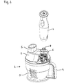
- a kitchen appliance 1 which comprises a lid 2 according to the invention and a vessel 3 according to the invention, the lid 2 being placed on the vessel 3 and attached thereto by means of a part 23 of a bayonet closure (see Fig. 4 ) on the cover 2 and a part of the bayonet fitting on the lid 2 corresponding part of the bayonet closure (see Fig. 3 ) is attached to the vessel 3.
- a part 23 of a bayonet closure see Fig. 4
- a part of the bayonet fitting on the lid 2 corresponding part of the bayonet closure see Fig. 3
- At least the vessel wall of the vessel 3 is made of a transparent plastic and is provided with volume and / orperssdorfan interconnect the vessel 3 with the desired amount of food.
- the vessel 3 is equipped with a handle 4 for easier handling.
- the lid 2 has on its outside a filling opening 5 for filling a food in the vessel 3.
- the filled through the filling opening 5 food passes through the lid 2 in the vessel 3.
- the filling opening 5 can be closed with a Einhellö Anlagensdeckel 25.
- the lid 2 with a Tool drive attachment 6 equipped, with the example, a mixing rod 7 can be attached as a tool drive.
- a tool drive coupling 8 of the cover 2 cooperates with a tool coupling (not shown) of the tool drive 7 in such a way that a rotational movement of the tool coupling is transmitted to the tool drive coupling 8 of the lid 2.
- These tool coupling can be rotatably connected to the tool drive coupling 8.
- a dicing unit is provided as a processing tool 26 in the vessel 3, which is releasably secured to the lid 2 by means of another bayonet closure with part 29 on the machining tool 26 and corresponding part 30 on the lid 2 and a in Fig. 4 visible tool coupling 27 of the lid 2 is driven.
- Foods introduced into the kitchen appliance 1 through the filling opening 5 are cut into cubes by the processing tool and subsequently fall to the bottom of the vessel 3.
- the detachable safety coupling 9 of the lid has an upper coupling 10 and a lower counter-coupling 11, wherein the coupling 10 and counter-coupling 11 are designed as toothed couplings.
- the teeth of the coupling 10 and the counter-coupling 11 engage in one another in a form-fitting manner.
- a clutch shift arm 12 By moving a clutch shift arm 12 downwards, the lower mating clutch 11 can be separated from the upper clutch 10.
- a designed as a lever clutch switch 13 is shown, which can cooperate with a cylindrical, attached to the upper outer wall of the vessel actuator 14. The figure shows the clutch switch 13 in its "closed" position.
- the lid 2 was attached in the fastening direction 15 to the vessel 3 by means of screw or bayonet closure, so that the actuating element 14 engages in a U-shaped recess of the clutch switch 13 and this clockwise from a "solved” - in the illustrated "closed” - Position moves.
- the clutch switch 13 can be moved from the "closed” position to the "released” position.
- a leg spring as a clutch switch restoring element 16 ensures that the clutch switch 13 remains in the "released” position when not actuated, in which the safety clutch 9 is in its released state.
- the safety clutch 9 is substantially reciprocated between the closed state and the released state by the clutch switch 13 with its clutch switch restoring member 16, an operating rod 17 having a biasing spring 18, and the clutch switching arm 12 also having a clutch cut-off spring 19.
- the biasing spring 18 in turn acts on the Kupplungsschaltarm 12, which is also acted upon by the force of a Kupplungsabschaltfeder 19.
- the force thereof is greater than the force of the clutch cutoff spring 19, so that the force of the clutch cutoff spring 19 is overcome by the force of the biasing spring 18 and thereby the clutch shift arm 12 brings the safety clutch 9 into the closed state.
- teeth of the upper coupling 10 of the safety clutch engage in teeth of the lower counter-coupling 11, as far as the coupling 10 and counter-coupling 11 are suitable to one another. If the teeth of the coupling 10 and the counter-coupling 11 should not be suitable to interlock, but instead only sit on each other, they reach at the latest by a first movement of the clutch 10 relative to the counter-coupling 11 in a suitable position to then slide into each other ,
- the clutch 10 of the safety clutch 9 is connected via a gear 21 to a drive shaft, at the end of the tool drive clutch 8 is mounted.
- the clutch 10 of the safety clutch 9 is set in rotation and this in turn transmits the rotation of the counter-coupling 11.
- the counter-coupling 11 is in turn via another gear 22 connected to an output shaft, which drives the mounted on the lid 2 and arranged in the vessel 3 processing tool 26 via the tool coupling 27.
Description
Die Erfindung betrifft einen Deckel, der an ein Gefäß für die Bearbeitung eines in dem Gefäß vorliegenden Lebensmittels lösbar anbringbar ist und der die Bewegung eines Werkzeugantriebs auf ein Bearbeitungswerkzeug für die Bearbeitung des Lebensmittels in dem Gefäß übertragen kann. Weiter betrifft die Erfindung ein Küchengerät, das einen solchen Deckel umfasst.The invention relates to a lid, which is detachably attachable to a vessel for processing a food present in the vessel and which can transmit the movement of a tool drive to a processing tool for processing the food in the vessel. Furthermore, the invention relates to a kitchen appliance comprising such a lid.
Küchenmaschinen weisen zum Antrieb üblicherweise einen in die Küchenmaschine integrierten Motor und eine Leistungsübertragungseinrichtung zum Übertragen der Motorleistung auf ein Bearbeitungswerkzeug, mit dem ein in einem Gefäß vorliegendes Lebensmittel bearbeitet werden kann, auf. Bei einigen Küchenmaschinen ist der Motor lösbar an der Küchenmaschine anbringbar, zum Beispiel in Form eines lösbar anbringbaren Handrührers oder Mixstabs zum Antreiben des Bearbeitungswerkzeugs der Küchenmaschine. Sowohl Küchenmaschinen mit integrierten Motor als auch Küchenmaschinen mit lösbar-anbringbaren Motor kommen sowohl als "L"-Typ-Küchenmaschinen, bei denen der Motor neben dem Gefäß angeordnet ist, als auch als "I"-Typ-Küchenmaschinen, bei dem der Motor über oder unter dem Gefäß angeordnet ist, vor.Food processors usually have a motor integrated into the food processor and a power transmission device for transmitting the engine power to a processing tool with which a food present in a vessel can be processed. In some food processors, the motor is detachably attachable to the food processor, for example in the form of a releasably attachable hand mixer or blender for driving the processing tool of the food processor. Both integrated motor-driven kitchen machines and detachably-attachable motor-driven kitchen machines come both as "L" -type food processors in which the motor is located adjacent to the vessel, and as "I" -type food processors in which the engine is over or placed under the vessel before.
Aus der Gebrauchsmusterschrift
Zum Betrieb der in der Gebrauchsmusterschrift
Ein Nachteil der aus der Gebrauchsmusterschrift
Ähnlich zur Gebrauchsmusterschrift
Aus der Patentschrift
Die europäische Offenlegungsschrift
Aus der Auslegungsschrift
Schließlich ist eine "L"-Typ-Küchenmaschine des Herstellers Philips bekannt, bei der zum Antrieb ein integrierter Elektromotor vertikal angeordnet ist und mit dem oberen Ende der Motorwelle einen Mixer antreibt. Das untere Ende der Motorwelle treibt eine Riemenscheibe an, die über einen Zahnriemen eine Werkzeugwelle der Küchenmaschine antreibt. Die Riemenscheibe weist eine lösbare Kupplung auf, die durch einen Schalthebel betätigbar ist. Wenn der Mixer auf der Küchenmaschine befestigt wird, wird dadurch die Kupplung mittels einer Betätigungsstange gelöst, sodass der Antrieb von der Werkzeugwelle entkoppelt ist und der Motor nur noch den Mixer antreibt. Dies soll einen ruhigen und gleichmäßigen Lauf der Küchenmaschine bei Benutzung des Mixers ermöglichen.Finally, an "L" -type food processor manufacturer Philips is known in which the drive is an integrated electric motor arranged vertically and with the upper end of the motor shaft drives a mixer. The lower end of the motor shaft drives a pulley, which drives a tool shaft of the food processor via a toothed belt. The pulley has a releasable coupling which is actuable by a shift lever. When the blender is mounted on the food processor, the clutch is released by means of an actuating rod so that the drive is decoupled from the tool shaft and the motor drives only the mixer. This should allow a smooth and even run of the food processor when using the mixer.
Der Erfindung liegt die Aufgabe zugrunde, ein verbesserten Deckel von dem Typ, der an ein Gefäß für die Bearbeitung eines in dem Gefäß vorliegenden Lebensmittel lösbar anbringbar ist und der die Bewegung eines Werkzeugantriebs auf ein Bearbeitungswerkzeug für die Bearbeitung des Lebensmittels in dem Gefäß übertragen kann, bereit zu stellen. Weiterhin liegt der Erfindung die Aufgabe zugrunde, ein verbessertes Küchengerät mit einem solchen Deckel bereitzustellen.It is an object of the present invention to provide an improved lid of the type which is detachable to a vessel for processing a food present in the vessel attachable and that can transmit the movement of a tool drive to a processing tool for processing the food in the vessel. Furthermore, the invention has for its object to provide an improved kitchen appliance with such a lid.
Durch die Erfindung sollen Nachteile bekannter Deckel und Küchengeräte überwunden werden. Insbesondere soll ein sicherer Betrieb gewährleistet werden, ohne dass Teile, insbesondere ein Werkzeugantrieb, von dem Deckel entfernt werden müssen. Auch soll es durch die Erfindung erreichbar sein, auf Mittel zum Bremsen einer Rotation eines Werkzeugantriebs oder eines Werkzeuges zu verzichten.The invention is intended to overcome disadvantages of known lids and kitchen appliances. In particular, a safe operation is to be ensured without parts, in particular a tool drive, must be removed from the lid. It should also be achievable by the invention to dispense with means for braking a rotation of a tool drive or a tool.
Die Bezugszeichen in sämtlichen Ansprüchen haben keine einschränkende Wirkung, sondern sollen lediglich deren Lesbarkeit verbessern.The reference numbers in all claims have no limiting effect, but are only intended to improve their readability.
Zum Lösen der Aufgabe lehrt die Erfindung einen Deckel gemäß Anspruch 1 und ein Küchengerät nach Anspruch 11. Der Deckel ist an ein Gefäß für die Bearbeitung eines in dem Gefäß vorliegenden Lebensmittels lösbar anbringbar und kann die Bewegung eines Werkzeugantriebs auf ein Bearbeitungswerkzeug für die Bearbeitung des Lebensmittels in dem Gefäß übertragen. Außerdem weist der Deckel eine lösbare Sicherheitskupplung auf, um die Bewegung des Werkzeugantriebs auf das Werkzeug im geschlossenen Zustand zu übertragen und im gelösten Zustand diese Übertragung zu unterbrechen. Hierbei kann der Deckel entweder direkt an das Gefäß anbringbar sein oder indirekt über ein Zwischenelement, zum Beispiel einen Adapter. "Lösen" der Sicherheitskupplung bedeutet im Zusammenhang mit der vorliegenden Erfindung, dass die Wirkverbindung zwischen Werkzeugantrieb und Bearbeitungswerkzeug unterbrochen wird.To solve the problem, the invention teaches a lid according to claim 1 and a kitchen appliance according to claim 11. The lid is detachably attachable to a vessel for processing a food present in the vessel and can the movement of a tool drive on a processing tool for processing the food transferred in the vessel. In addition, the lid has a releasable safety coupling to transmit the movement of the tool drive to the tool in the closed state and to interrupt this transmission in the dissolved state. In this case, the lid can be attached either directly to the vessel or indirectly via an intermediate element, for example an adapter. In the context of the present invention, "releasing" the safety coupling means that the operative connection between the tool drive and the machining tool is interrupted.
Der Deckel weist einen Kupplungsschalter auf, der die Sicherheitskupplung abhängig von der Verbindung zwischen dem Deckel und dem Gefäß schließen und lösen kann. Mit der Erfindung kann vorteilhafterweise erreicht werden, dass die Kupplung sich dann in einem gelösten Zustand befindet, wenn das Werkzeug durch Lösen oder Trennen des Deckels von dem Gefäß von außen zugänglich wird. Insbesondere ist erreichbar, dass die Antriebseinheit bei Öffnung des Deckels mit diesem verbunden bleiben kann, ohne dass eine Gefahr von dem Werkzeug ausgeht. Die Sicherheitskupplung kann so vorteilhafterweise verhindern, dass das Werkzeug bei geöffnetem Deckel angetrieben wird.The lid has a clutch switch which can close and release the safety clutch depending on the connection between the lid and the vessel. With the invention can be advantageously achieved that the coupling is then in a dissolved state when the tool is accessible by loosening or separating the lid of the vessel from the outside. In particular, it can be achieved that the drive unit can remain connected to the lid when opening, without any danger emanating from the tool. The safety coupling can thus advantageously prevent the tool from being driven when the cover is open.
Weiterhin wird die Aufgabe durch ein Küchengerät gelöst, das einen solchen Deckel und ein Gefäß für die Bearbeitung eines in dem Gefäß vorliegenden Lebensmittels, an dem der Deckel lösbar angebracht werden kann, umfasst. Das Küchengerät ist vorzugsweise eine Küchenmaschine, besonders vorzugsweise eine Standküchenmaschine, zum Beispiel vom "I"-Typ oder vom "L"-Typ.Furthermore, the object is achieved by a kitchen appliance comprising such a lid and a vessel for processing a food present in the vessel to which the lid can be releasably attached. The kitchen appliance is preferably a food processor, more preferably a stand-alone food processor, for example of the "I" type or of the "L" type.
Es ist ein erreichbarer Vorteil der Erfindung, dass die Sicherheit der Bearbeitung des Lebensmittels in dem Gefäß mittels des Bearbeitungswerkzeugs verbessert werden kann. Dadurch, dass die Sicherheitskupplung im gelösten Zustand die Übertragung der Bewegung des Werkzeugantriebs auf das Werkzeug unterbrechen kann, kann vermieden werden, dass zum Anhalten der Bewegung des Bearbeitungswerkzeugs zunächst der Werkzeugantrieb vom Deckel gelöst werden muss. Auch ist vorteilhaft erreichbar, dass das Werkzeug schnell zum Stehen gebracht werden kann. Insbesondere ist es mit der Erfindung möglich, dass keine Bremsmittel erforderlich sind, um den Antrieb abzubremsen. Vielmehr lässt sich erreichen, dass das Bearbeitungswerkzeug bereits zum Stehen kommt, wenn der Werkzeugantrieb noch ausläuft.It is an achievable advantage of the invention that the safety of processing the food in the vessel can be improved by means of the processing tool. The fact that the safety clutch in the dissolved state, the transmission of the Movement of the tool drive can interrupt the tool, it can be avoided that to stop the movement of the machining tool first the tool drive must be released from the lid. It is also advantageously achievable that the tool can be brought to a standstill quickly. In particular, it is possible with the invention that no braking means are required to decelerate the drive. Rather, it can be achieved that the machining tool comes to a halt when the tool drive still expires.
Vorteilhafte Aus- und Weiterbildungen, welche einzeln oder in Kombination miteinander eingesetzt werden können, sind Gegenstand der abhängigen Ansprüche.Advantageous embodiments and developments, which can be used individually or in combination with each other, are the subject of the dependent claims.
Vorzugsweise stehen der Kupplungsschalter und die Sicherheitskupplung in der Weise miteinander in Verbindung, dass eine Drehung des Kupplungsschalters eine translatorische Bewegung eines Teils der Sicherheitskupplung bewirkt.Preferably, the clutch switch and the safety clutch are in communication with each other in such a way that rotation of the clutch switch causes a translational movement of a part of the safety clutch.
Der bevorzugte Kupplungsschalter weist eine "Gelöst"-Stellung auf, in der sich die Sicherheitskupplung in dem gelösten Zustand befindet, indem die Übertragung der Bewegung des Werkzeugantriebs auf das Bearbeitungswerkzeug unterbrochen ist, und eine davon verschiedene "Geschlossen"-Stellung, in der sich die Sicherheitskupplung in ihrem geschlossenen Zustand befindet, in dem die Bewegung des Werkzeugantriebes auf das Bearbeitungswerkzeug übertragen durch die Sicherheitskupplung übertragen wird.The preferred clutch switch has a "released" position in which the safety clutch is in the released state by interrupting the transmission of the movement of the tool drive to the machining tool, and a different "closed" position in which the Safety clutch is in its closed state, in which the movement of the tool drive transmitted to the machining tool is transmitted through the safety clutch.
"Verbindung" im Sinne der vorliegenden Erfindungsbeschreibung bedeutet, ob oder wie der Deckel mit dem Gefäß verbunden ist. Zum Beispiel kann die Kupplung in dem auf das Gefäß aufgesetzten Zustand des Deckels geschlossen und in dem von dem Gefäß getrennten Zustand des Deckels gelöst sein. In einer bevorzugten Ausführung der Erfindung ist der Deckel an dem Gefäß befestigbar. Vorzugsweise kann die Kupplung in diesem Fall in dem an dem Gefäß befestigten Zustand des Deckels geschlossen und in dem an dem Gefäß unbefestigten Zustand des Deckels gelöst sein."Connection" in the sense of the present invention description means whether or how the lid is connected to the vessel. For example, the coupling may be closed in the state of the lid fitted to the vessel and released in the state of the lid which is separate from the vessel. In a preferred embodiment of the invention, the lid is attachable to the vessel. Preferably, in this case, the coupling can be closed in the state of the lid fastened to the vessel and released in the state of the lid which is unattached to the vessel.
Der bevorzugte Kupplungsschalter ist als Hebel ausgebildet, besonders vorzugsweise als Drehhebel. In dieser Ausführung der Erfindung kann der Kupplungsschalter durch Drehen eines Hebelarms des Drehhebels zwischen der "Gelöst"- Stellung und der "Geschlossen"-Stellung hin- und herbewegt werden. Ein bevorzugter Kupplungsschalter ist gabelförmig in dem Sinne, dass er eine Aussparung aufweist, ausgeführt. Die bevorzugte Aussparung ist im Wesentlichen U-förmig ausgebildet. Die Aussparung befindet sich bei dem Drehhebel vorzugsweise am vom Drehpunkt des Drehhebels entfernten Ende des Hebelarms.The preferred clutch switch is designed as a lever, particularly preferably as a rotary lever. In this embodiment of the invention, the clutch switch can be reciprocated by rotating a lever arm of the rotary lever between the "released" position and the "closed" position. A preferred clutch switch is fork-shaped in the sense that it has a recess executed. The preferred recess is substantially U-shaped. The recess is located at the rotary lever preferably at the remote from the pivot point of the rotary lever end of the lever arm.
Der bevorzugte Kupplungsschalter wirkt mit einem an dem Gefäß angeordneten Betätigungselement zusammen. Alternativ wirkt der Kupplungsschalter mit einem an dem Verbindungselement zwischen Deckel und Gefäß angebrachten Betätigungselement zusammen. Das bevorzugte Betätigungselement kann in die Aussparung des Kupplungsschalters eingreifen. Der bevorzugte Kupplungsschalter ist so ausgebildet, dass er durch ein Drehen des Deckels relativ zum Gefäß betätigbar ist, insbesondere von der "Gelöst" in die "Geschlossen"-Stellung gebracht werden kann.The preferred clutch switch cooperates with an actuator disposed on the vessel. Alternatively, the clutch switch cooperates with an attached to the connecting element between the lid and vessel actuator. The preferred actuator may engage the recess of the clutch switch. The preferred clutch switch is designed so that it can be actuated by turning the lid relative to the vessel, in particular can be brought from the "dissolved" in the "closed" position.
Das bevorzugte Betätigungselement ist als Vorsprung, besonders vorzugsweise als zylindrischer Vorsprung ausgebildet. Es befindet sich vorzugsweise an einer Außenwand des Gefäßes, besonders vorzugsweise knapp unterhalb des oberen Rands des Gefäßes. Das bevorzugte Betätigungselement kann in die Aussparung des Kupplungsschalters eingreifen, um diesen bei relativer Bewegung, vorzugsweise eine Drehbewegung oder eine schraubenartige Bewegung, von Deckel und Gefäß von der "Gelöst"-Stellung in die "Geschlossen"-Stellung zu bewegen.The preferred actuating element is designed as a projection, particularly preferably as a cylindrical projection. It is preferably located on an outer wall of the vessel, more preferably just below the upper edge of the vessel. The preferred actuator may engage the recess of the clutch switch to move it from the "released" position to the "closed" position during relative movement, preferably rotational or helical motion, of the lid and vessel.
Der bevorzugte Deckel weist ein Kupplungsschalterrückstellelement auf, um den Kupplungsschalter bei Nichtbetätigung in die Stellung vorzuspannen, in der die Sicherheitskupplung sich in ihrem gelösten Zustand befindet. Das Rückstellelement kann zum Beispiel eine Feder sein, zum Beispiel eine Schenkelfeder. Mit dieser Ausführung der Erfindung ist vorteilhaft erreichbar, dass der Kupplungsschalter, wenn er nicht mit dem Betätigungselement zusammen wirkt, sich in der "Gelöst"-Stellung befindet, in der die Sicherheitskupplung sich in ihrem gelösten Zustand befindet.The preferred lid has a clutch switch reset member to bias the clutch switch in the non-actuation to the position in which the safety clutch is in its released state. The return element may be for example a spring, for example a leg spring. With this embodiment of the invention is advantageously achieved that the clutch switch when it does not interact with the actuator is in the "released" position, in which the safety clutch is in its dissolved state.
Ein bevorzugter Deckel weist Befestigungsmittel auf, um den Deckel an dem Gefäß lösbar zu befestigen. Weiterhin weist vorzugsweise das Gefäß oder das Zwischenelement zu den Befestigungsmitteln des Deckels korrespondierende Befestigungsmittel auf. Die Befestigungsmittel sind vorzugsweise so ausgebildet, dass der Deckel durch Drehen lösbar an dem Gefäß befestigt werden kann. Besonders vorteilhaft ist erreichbar, dass durch die Drehung sowohl der Deckel an dem Gefäß befestigt als auch die Sicherheitskupplung betätigt wird.A preferred lid has attachment means for releasably securing the lid to the vessel. Furthermore, the vessel or the intermediate element preferably has fastening means corresponding to the fastening means of the lid. The fastening means are preferably formed so that the lid by turning can be releasably attached to the vessel. It is particularly advantageous to achieve that both the lid attached to the vessel by the rotation and the safety clutch is actuated.
Ein erfindungsgemäßes Befestigungsmittel an dem Deckel kann zum Beispiel ein Gewinde sein, das mit einem Gegengewinde des Gefäßes oder dem Zwischenelement zusammenwirken kann, um den Deckel an dem Gefäß lösbar zu befestigen. Alternativ kann ein erfindungsgemäßes Befestigungsmittel ein Element eines Bajonettverschlusses sein. Der Deckel und das Gefäß oder der Deckel und das Zwischenelement können korrespondierende Elemente eines Bajonettverschlusses aufweisen, um den Deckel an dem Gefäß lösbar zu befestigen.An attachment means according to the invention on the cover may, for example, be a thread which can cooperate with a mating thread of the vessel or the intermediate element to releasably secure the cover to the vessel. Alternatively, a fastener according to the invention may be an element of a bayonet closure. The lid and the vessel or lid and the intermediate member may have corresponding elements of a bayonet closure for releasably securing the lid to the vessel.
Der Werkzeugantrieb weist vorzugsweise einen Elektromotor auf. Dieser kann durch ein Stromkabel und/oder durch in dem Werkzeugantrieb vorliegende Batterien versorgbar sein. Besonders vorzugsweise sind die Batterien drahtlos aufladbar. Die Erfindung umfasst aber auch solche Ausführungen, bei denen die Batterien durch ein Kabel aufladbar sind. Der Werkzeugantrieb kann an den Deckel lösbar anbringbar sein. Als lösbarer Werkzeugantrieb kommen zum Beispiel ein Handrührer, ein Handmixer oder eine anderes Küchengerät, z.B. eine Küchenmaschine, in Frage. In einer alternativen Ausführung der Erfindung ist der Werkzeugantrieb unlösbarer Teil des Deckels.The tool drive preferably has an electric motor. This can be supplied by a power cable and / or present in the tool drive batteries. Particularly preferably, the batteries are wirelessly rechargeable. However, the invention also includes such embodiments in which the batteries are rechargeable by a cable. The tool drive may be releasably attachable to the lid. As a detachable tool drive come, for example, a hand mixer, a hand mixer or other kitchen appliance, e.g. a food processor, in question. In an alternative embodiment of the invention, the tool drive is an insoluble part of the lid.
In einer bevorzugten Ausführung der Erfindung weist der Deckel eine Antriebskupplung auf, um den Werkzeugantrieb lösbar an den Deckel anzukuppeln. Die Antriebskupplung kann zum Beispiel eine Zahnkupplung sein. Vorzugsweise ist die Antriebskupplung an einer Antriebswelle angeordnet, die eine Drehbewegung des Werkzeugantriebs direkt oder indirekt, zum Beispiel über ein Getriebe, zu der Sicherheitskupplung weiterleitet.In a preferred embodiment of the invention, the lid has a drive coupling to releasably couple the tool drive to the lid. The drive coupling may be, for example, a toothed clutch. Preferably, the drive coupling is arranged on a drive shaft, which forwards a rotational movement of the tool drive directly or indirectly, for example via a transmission, to the safety clutch.
Ein bevorzugter Deckel weist eine Werkzeugkupplung auf, um das Werkzeug lösbar an den Deckel anzukuppeln. Mit dieser Ausführung der Erfindung kann das Werkzeug vorteilhafterweise an Deckel ankuppelbar, besonders vorzugsweise austauschbar sein. Die Werkzeugkupplung kann zum Beispiel eine Zahnkupplung sein. Vorzugsweise ist die Werkzeugkupplung an einer Abtriebswelle angeordnet, um das Bearbeitungswerkzeug über die Werkzeugkupplung drehend anzutreiben. In einer alternativen Ausführung der Erfindung ist das Bearbeitungswerkzeug unlösbarer Teil des Deckels.A preferred lid has a tool coupling for releasably coupling the tool to the lid. With this embodiment of the invention, the tool can advantageously be coupled to cover, particularly preferably be interchangeable. The tool coupling may be, for example, a toothed coupling. Preferably, the tool coupling is disposed on an output shaft to rotationally drive the machining tool via the tool coupling. In an alternative embodiment of the invention, the machining tool is insoluble part of the lid.
Das bevorzugte Werkzeug dient der mechanischen Verarbeitung von Lebensmitteln, zum Beispiel durch Schneiden, Zerhacken, Würfeln, Zerdrücken, Passieren, Reiben und/oder Raspeln. Ein bevorzugtes Werkzeug hat eine Schneide zum Schneiden von Lebensmitteln. Zum Beispiel kann das Werkzeug mehrere Messer zum Zerhacken oder Schneiden aufweisen. Das Werkzeug kann eine Scheibe mit einem oder mehreren Schneidschlitzen, zum Bespiel zum Schneiden von Gemüsescheiben sein. Ein weiteres geeignetes Werkzeug ist eine Würfelschneideinheit, vorzugsweise eine Würfelschneideinheit von dem Typ, der eine Gitterscheibe aufweist, beispielsweise die aus der Gebrauchsmusterschrift
Ein besonders bevorzugter Deckel weist ein oder mehrere Getriebe auf. In einer Ausführung der Erfindung ist ein Getriebe zwischen Werkzeugantrieb und Sicherheitskupplung, besonders vorzugsweise zwischen Antriebskupplung und Sicherheitskupplung, angebracht. In einer bevorzugten Ausführung des Deckels ist ein Getriebe zwischen Sicherheitskupplung und Werkzeug, besonders vorzugsweise zwischen Sicherheitskupplung und Werkzeugkupplung, angebracht. Es sind auch Ausführungen der Erfindung mit mehreren Getrieben Teil der vorliegenden Erfindung, wobei besonders vorzugsweise ein Getriebe zwischen Werkzeugantrieb und Sicherheitskupplung, besonders vorzugsweise zwischen Antriebskupplung und Sicherheitskupplung, und ein anderes Getriebe zwischen Sicherheitskupplung und Werkzeug, besonders vorzugsweise zwischen Sicherheitskupplung und Werkzeugkupplung, angeordnet ist.A particularly preferred lid has one or more transmissions. In one embodiment of the invention, a transmission between the tool drive and the safety clutch, particularly preferably between the drive clutch and the safety clutch, mounted. In a preferred embodiment of the cover, a transmission between the safety coupling and tool, particularly preferably between safety coupling and tool coupling, mounted. There are also embodiments of the invention with multiple transmissions part of the present invention, wherein particularly preferably a transmission between the tool drive and safety clutch, particularly preferably between the drive clutch and safety clutch, and another gear between the safety clutch and tool, particularly preferably between the safety clutch and the tool coupling, is arranged.
In einer bevorzugten Ausführung der Erfindung ist die Sicherheitskupplung des Deckels formschlüssig. Die bevorzugte Sicherheitskupplung ist eine Zahnkupplung, die mit einer Eingangswelle der Sicherheitskupplung drehfest verbunden ist, und einer Gegenzahnkupplung, die mit einer Ausgangswelle der Sicherheitskupplung drehfest verbunden ist. Vorzugsweise greifen die Zähne der Zahnkupplung und die Zähne der Gegenzahnkupplung greifen im geschlossenen Zustand der Sicherheitskupplung ineinander, um Eingangswelle und Ausgangswelle drehfest miteinander zu verbinden, und im gelösten Zustand der Kupplung nicht ineinander, sodass Eingangs- und Ausgangswelle nicht in Wirkverbindung stehen. Alternativ kann die Sicherheitskupplung auch kraftschlüssig ausgebildet sein.In a preferred embodiment of the invention, the safety coupling of the lid is positively. The preferred safety clutch is a toothed coupling, which is rotatably connected to an input shaft of the safety clutch, and a counter-toothed coupling, which is rotatably connected to an output shaft of the safety clutch. Preferably, the teeth of the toothed coupling and the teeth of the counter-toothed mesh in the closed state of the safety coupling in each other to rotatably connect the input shaft and output shaft with each other, and not in the dissolved state of the coupling, so that input and output shaft are not in operative connection. Alternatively, the safety coupling can also be formed non-positively.
Vorzugsweise wird die Sicherheitskupplung durch einen Kupplungsschaltarm betätigt, auf den in eine Richtung die Kraft einer Vorspannfeder und in eine andere, vorzugsweise entgegengesetzte Richtung die Kraft einer Kupplungsabschaltfeder wirkt. Die Vorspannfeder wird, vorzugweise indirekt, durch den Kupplungsschalter in der Weise betätigt, dass ihre Kraft auf den Kupplungsschaltarm in der "Geschlossen"-Stellung des Kupplungsschalters größer ist als die Kraft der Kupplungsabschaltfeder, und dadurch die Kraft der Kupplungsabschaltfeder durch die Kraft der Vorspannfeder überwunden wird, sodass der Kupplungsschaltarm die Sicherheitskupplung in den geschlossenen Zustand bringt. Hingegen ist die Kraft der Vorspannfeder auf den Kupplungsschaltarm in der "Gelöst"-Stellung des Kupplungsschalters kleiner als die Kraft der Kupplungsabschaltfeder, sodass die Kupplungsabschaltfeder die Sicherheitskupplung in den gelösten Zustand bringt.Preferably, the safety clutch is actuated by a Kupplungsschaltarm, acts in the one direction, the force of a biasing spring and in another, preferably opposite direction, the force of a Kupplungsabschaltfeder. The bias spring is actuated, preferably indirectly, by the clutch switch in such a manner that its force on the clutch shift arm in the "closed" position of the clutch switch is greater than the force of the clutch cutoff spring, thereby overcoming the force of the clutch cutoff spring by the force of the biasing spring so that the clutch shift arm brings the safety clutch in the closed state. On the other hand, the force of the biasing spring on the clutch switch arm in the "released" position of the clutch switch is smaller than the force of the clutch cutoff spring, so that the clutch cutoff spring brings the safety clutch in the released state.
Der bevorzugte Deckel weist eine Einfüllöffnung zum Einfüllen eines Lebensmittels in das Bearbeitungsgefäß auf. Bei dieser Ausführung der Erfindung können vorteilhafterweise in die Einfüllöffnung zugeführte Lebensmittel durch den Deckel in das Gefäß gelangen und dort vom Bearbeitungswerkzeug bearbeitet werden. Von dort fallen Sie vorzugsweise zum Boden des Gefäßes.The preferred lid has a filling opening for filling a food into the processing vessel. In this embodiment of the invention, foodstuffs fed into the filling opening can advantageously pass through the lid into the vessel where they are processed by the processing tool. From there, you preferably fall to the bottom of the vessel.
Das Gefäß weist allgemein einen Boden und eine um den Boden umlaufende sich nach oben erstreckende Wand auf. Nach obenhin ist das Gefäß offen; durch diese Öffnung kann insbesondere das Lebensmittel in das Gefäß eingefüllt werden. Außerdem kann der der Deckel, eventuell vermittels des Zwischenelements, auf das Gefäß aufgesetzt werden. Das Gefäß kann zum Beispiel eine Rührschüssel oder ein Mixbecher sein. Ein bevorzugtes Gefäß weist einen Griff auf.The vessel generally has a bottom and a wall extending upwardly around the bottom. The vessel is open at the top; In particular, the food can be filled into the vessel through this opening. In addition, the lid, possibly by means of the intermediate element, can be placed on the vessel. The vessel may be, for example, a mixing bowl or a shaker. A preferred vessel has a handle.
Eine vorteilhafte Ausgestaltung der Erfindung wird nachfolgend anhand eines in den Zeichnungen dargestellten Ausführungsbeispiels, auf welche die Erfindung jedoch nicht beschränkt ist, näher beschrieben.An advantageous embodiment of the invention will be described in more detail below with reference to an embodiment shown in the drawings, to which the invention is not limited.
Es zeigen schematisch:
- Fig. 1
- in perspektivischer Ansicht ein erfindungsgemäßes Küchengerät mit einem Deckel und einem Gefäß sowie den an das Küchengerät anbringbaren Werkzeugantrieb;
- Fig. 2
- in perspektivischer Aufrissansicht einen Teil des auf dem Gefäß angebrachten Deckels mit der erfindungsgemäßen Sicherheitskupplung;
- Fig. 3
- eine perspektivische Expositionsdarstellung des erfindungsgemäßen Küchengeräts; und
- Fig. 4
- in perspektivischer Ansicht der erfindungsgemäße Deckel von unten.
- Fig. 1
- in perspective view of an inventive kitchen appliance with a lid and a vessel and attachable to the kitchen appliance tool drive;
- Fig. 2
- a perspective elevation view of a portion of the lid mounted on the vessel with the safety coupling according to the invention;
- Fig. 3
- a perspective exposure representation of the kitchen appliance according to the invention; and
- Fig. 4
- in a perspective view of the lid according to the invention from below.
Die in der vorstehenden Beschreibung, den Ansprüchen und den Zeichnungen offenbarten Merkmale können sowohl einzeln als auch in beliebiger Kombination für die Verwirklichung der Erfindung in ihren verschiedenen Ausgestaltungen von Bedeutung sein.The features disclosed in the foregoing description, the claims and the drawings may be of importance both individually and in any combination for the realization of the invention in its various forms.
In der
Der Deckel 2 weist auf seiner Außenseite eine Einfüllöffnung 5 zum Einfüllen eines Lebensmittels in das Gefäß 3 auf. Das durch die Einfüllöffnung 5 eingefüllte Lebensmittel gelangt durch den Deckel 2 in das Gefäß 3. Die Einfüllöffnung 5 kann mit einem Einfüllöffnungsdeckel 25 verschlossen werden. Weiterhin ist der Deckel 2 mit einer Werkzeugantriebsbefestigung 6 ausgestattet, mit der zum Beispiel ein Mixstab 7 als Werkzeugantrieb befestigt werden kann. Eine Werkzeugantriebskupplung 8 des Deckels 2 wirkt mit einer Werkzeugkupplung (nicht dargestellt) des Werkzeugantriebs 7 in der Weise zusammen, dass eine Drehbewegung der Werkzeugkupplung auf die Werkzeugantriebskupplung 8 des Deckels 2 übertragen wird. Dazu können Werkzeugkupplung auf die Werkzeugantriebskupplung 8 drehfest miteinander verbunden werden.The
Außerdem ist in dem Gefäß 3 eine Würfelschneideinheit als Bearbeitungswerkzeug 26 vorgesehen, das an dem Deckel 2 mittels eines weiteren Bajonettverschlusses mit Teil 29 am Bearbeitungswerkzeug 26 und korrespondierendem Teil 30 am Deckel 2 lösbar befestigt und über eine in
In der
Im Folgenden werden weitere Komponenten des Deckels 2 und das Zusammenwirken der Komponenten im Einzelnen beschrieben. Die Sicherheitskupplung 9 wird im Wesentlichen durch den Kupplungsschalter 13 mit seinem Kupplungsschalterrückstellelement 16, einer Betätigungsstange 17 mit einer Vorspannfeder 18 und dem Kupplungsschaltarm 12, der außerdem eine Kupplungsabschaltfeder 19 aufweist, zwischen dem geschlossenen Zustand und dem gelösten Zustand hin- und herbewegt.In the following, further components of the
Der als gabelförmiger Hebel ausgebildete Kupplungsschalter 13 wird durch die Schenkelfeder 16 in seine Ausgangsposition, also die "Gelöst"-Stellung, die der gelösten Sicherheitskupplung entspricht, vorgespannt. Wenn nun der Deckel 2 durch Drehen in Befestigungsrichtung 15, d.h. in der Figur entgegen des Urzeigersinns, relativ zum Gefäß 3 an diesem befestigt wird, greift das Betätigungselement 14, in die U-förmige Aussparung des Kupplungsschalter 13 und dreht diesen im Uhrzeigersinn in die "Geschlossen"-Stellung. Dadurch wird eine Hebelwelle 20 des Kupplungsschalters 13 in Rotation versetzt und verschiebt die Betätigungsstange 17. Die Betätigungsstange 17 wirkt auf eine Vorspannfeder 18, wobei das Verschieben der Betätigungsstange 17 die Vorspannfeder 18 komprimiert. Die Vorspannfeder 18 wirkt ihrerseits auf den Kupplungsschaltarm 12, der außerdem mit der Kraft einer Kupplungsabschaltfeder 19 beaufschlagt ist. In dem durch die Betätigungsstange 17 komprimierten Zustand der Vorspannfeder 18 ist deren Kraft jedoch größer als die Kraft der Kupplungsabschaltfeder 19, sodass die Kraft der Kupplungsabschaltfeder 19 durch die Kraft der Vorspannfeder 18 überwunden und dadurch der Kupplungsschaltarm 12 die Sicherheitskupplung 9 in den geschlossenen Zustand bringt.Trained as a fork-shaped lever
In diesem Zustand greifen Zähne der oberen Kupplung 10 der Sicherheitskupplung in Zähne der unteren Gegenkupplung 11, soweit Kupplung 10 und Gegenkupplung 11 geeignet zueinander stehen. Falls die Zähne der Kupplung 10 und der Gegenkupplung 11 nicht geeignet zueinander stehen sollten, um ineinander zu greifen, sondern stattdessen lediglich aufeinander sitzen, gelangen sie spätestens durch eine erste Bewegung der Kupplung 10 relativ zur Gegenkupplung 11 in eine geeignete Stellung um dann ineinander zu gleiten.In this state, teeth of the
Die Kupplung 10 der Sicherheitskupplung 9 ist über ein Getriebe 21 mit einer Antriebswelle verbunden, an deren Ende die Werkzeugantriebskupplung 8 angebracht ist.The clutch 10 of the safety clutch 9 is connected via a
Dadurch, dass die Werkzeugantriebskupplung 8 und damit die Antriebswelle durch den Werkzeugantrieb 7 in Rotation versetzt werden, wird auch die Kupplung 10 der Sicherheitskupplung 9 in Rotation versetzt und diese wiederum überträgt die Rotation auf die Gegenkupplung 11. Die Gegenkupplung 11 ist ihrerseits über ein weiteres Getriebe 22 mit einer Abtriebswelle verbunden, die über die Werkzeugkupplung 27 das an dem Deckel 2 angebrachte und in dem Gefäß 3 angeordnete Bearbeitungswerkzeug 26 antreibt.Characterized in that the
Die in der vorstehenden Beschreibung, den Ansprüchen und den Zeichnungen offenbarten Merkmale können sowohl einzeln als auch in beliebiger Kombination für die Verwirklichung der Erfindung in ihren verschiedenen Ausgestaltungen von Bedeutung sein.The features disclosed in the foregoing description, the claims and the drawings may be of importance both individually and in any combination for the realization of the invention in its various forms.
- 11
- Küchengerätkitchen appliance
- 22
- Deckelcover
- 33
- Gefäßvessel
- 44
- GriffHandle
- 55
- Einfüllöffnungfill opening
- 66
- WerkzeugantriebsbefestigungTool drive mounting
- 77
- MixstabMixstab
- 88th
- WerkzeugantriebskupplungTool drive coupling
- 99
- Sicherheitskupplungsafety clutch
- 1010
- (obere) Kupplung(upper) coupling
- 1111
- Gegenkupplungcounter-coupling
- 1212
- KupplungsschaltarmKupplungsschaltarm
- 1313
- Kupplungsschalterclutch switch
- 1414
- Betätigungselementjig
- 1515
- Befestigungsrichtungmounting direction
- 1616
- KupplungsschalterrückstellelementClutch switch reset element
- 1717
- Betätigungsstangeactuating rod
- 1818
- Vorspannfederbiasing spring
- 1919
- KupplungsabschaltfederKupplungsabschaltfeder
- 2020
- Hebelwellelever shaft
- 2121
- Getriebetransmission
- 2222
- Getriebetransmission
- 2323
-
Am Deckel 2 befindlicher Teil des BajonettverschlussesOn the
cover 2 located part of the bayonet lock - 2424
-
Am Gefäß 3 befindlicher Teil des BajonettverschlussesOn the
vessel 3 located part of the bayonet closure - 2525
- EinfüllöffnungsdeckelEinfüllöffnungsdeckel
- 2626
- Bearbeitungswerkzeugprocessing tool
- 2727
- Werkzeugkupplungtool coupling
- 2828
- WerkzeuggegenkupplungTool mating coupling
- 2929
-
Am Bearbeitungswerkzeug 26 befindlicher Teil des weiteren BajonettverschlussesOn the
machining tool 26 located part of the other bayonet lock - 3030
-
Am Deckel 2 befindlicher Teil des weiteren BajonettverschlussesOn the
cover 2 located part of the other bayonet lock
Claims (9)
- Cover (2) which can be releasably attached to a vessel (3) for processing a food item present in the vessel (3) and which can transmit the movement of a tool drive (7) onto a processing tool (26) for processing the food item in the vessel (3), characterised in that the cover (2) has a releasable safety coupling (9) in order to transmit the movement of the tool drive (7) onto the processing tool (26) in the closed state and in the detached state to interrupt this transmission, and the cover (2) has a coupling switch (13), which can close and release the safety coupling (9) as a function of the connection between the cover (2) and the vessel (3).
- Cover (2) according to claim 1, characterised in that it has a coupling switch return element (16), in order, upon non-actuation, to pretension the coupling switch (13) in the position in which the safety coupling (9) is disposed in its released state.
- Cover (2) according to one of the preceding claims, characterised in that the cover (2) has fastening means (23) for releasably fastening the cover (2) to the vessel (3).
- Cover (2) according to one of the preceding claims, characterised in that the cover (2) has a drive coupling (8) for releasably coupling the tool drive (7) to the cover (2).
- Cover (2) according to one of the preceding claims, characterised in that the cover (2) has a tool coupling (27) for releasably coupling the processing tool (26) to the cover (2).
- Cover (2) according to one of the preceding claims, characterised in that the cover has a transmission (21, 22).
- Cover (2) according to one of the preceding claims, characterised in that the safety coupling (9) is form-fit.
- Cover (2) according to claim 1, characterised in that it has a filler opening (5) for filling a food item into the processing vessel (3).
- Kitchenware (1) comprising a cover (2) according to one of the preceding claims and a vessel (3) for processing a food item present in the vessel (3), to which the cover (2) can be releasably attached.
Priority Applications (1)
| Application Number | Priority Date | Filing Date | Title |
|---|---|---|---|
| SI201530508T SI3185733T1 (en) | 2014-08-28 | 2015-08-20 | Processing vessel having a cover and a safety coupling |
Applications Claiming Priority (2)
| Application Number | Priority Date | Filing Date | Title |
|---|---|---|---|
| DE102014217244.6A DE102014217244A1 (en) | 2014-08-28 | 2014-08-28 | Processing vessel with lid and safety coupling |
| PCT/EP2015/069105 WO2016030261A1 (en) | 2014-08-28 | 2015-08-20 | Processing vessel having a cover and a safety coupling |
Publications (2)
| Publication Number | Publication Date |
|---|---|
| EP3185733A1 EP3185733A1 (en) | 2017-07-05 |
| EP3185733B1 true EP3185733B1 (en) | 2018-10-31 |
Family
ID=53879524
Family Applications (1)
| Application Number | Title | Priority Date | Filing Date |
|---|---|---|---|
| EP15751023.1A Active EP3185733B1 (en) | 2014-08-28 | 2015-08-20 | Processing vessel having a cover and a safety coupling |
Country Status (6)
| Country | Link |
|---|---|
| EP (1) | EP3185733B1 (en) |
| DE (1) | DE102014217244A1 (en) |
| ES (1) | ES2701419T3 (en) |
| HU (1) | HUE040497T2 (en) |
| SI (1) | SI3185733T1 (en) |
| WO (1) | WO2016030261A1 (en) |
Families Citing this family (1)
| Publication number | Priority date | Publication date | Assignee | Title |
|---|---|---|---|---|
| GR1009532B (en) * | 2018-05-03 | 2019-05-23 | ΣΩΚΡΑΤΗΣ Δ. ΚΩΝΣΤΑΝΤΙΝΟΥ ΚΑΙ ΥΙΟΣ Α.Ε. ΕΜΠΟΡΙΟ-ΒΙΟΜΗΧΑΝΙΑ ΥΑΛΙΚΩΝ ΚΑΙ ΕΙΔΩΝ ΟΙΚΙΑΚΗΣ ΧΡΗΣΗΣ με Δ.Τ. "YALCO" | Multi-cutter allowing the addition of liquids while operating |
Family Cites Families (6)
| Publication number | Priority date | Publication date | Assignee | Title |
|---|---|---|---|---|
| DE1179674B (en) * | 1962-08-31 | 1964-10-15 | Siemens Elektrogeraete Gmbh | Household appliances with rotating tools, such as mixer grinders, hammer mills, etc. like |
| DE4414415C1 (en) | 1994-04-25 | 1995-04-06 | Braun Ag | Attachment for an electrically operated hand mixer |
| FR2843535B1 (en) * | 2002-08-19 | 2005-02-11 | Seb Sa | CULINARY PREPARATION ELECTRICAL APPLIANCE COMPRISING A ROTARY TOOL AND A DOUBLE IMPROVED SAFETY DEVICE |
| DE10244717B4 (en) | 2002-09-25 | 2014-11-13 | BSH Bosch und Siemens Hausgeräte GmbH | household appliance |
| DE102011004483A1 (en) * | 2011-02-21 | 2012-08-23 | BSH Bosch und Siemens Hausgeräte GmbH | Tool and drive device for a motor-driven kitchen appliance |
| EP2564745A1 (en) | 2011-09-01 | 2013-03-06 | Koninklijke Philips Electronics N.V. | A lid for a food processor |
-
2014
- 2014-08-28 DE DE102014217244.6A patent/DE102014217244A1/en not_active Ceased
-
2015
- 2015-08-20 HU HUE15751023A patent/HUE040497T2/en unknown
- 2015-08-20 SI SI201530508T patent/SI3185733T1/en unknown
- 2015-08-20 EP EP15751023.1A patent/EP3185733B1/en active Active
- 2015-08-20 ES ES15751023T patent/ES2701419T3/en active Active
- 2015-08-20 WO PCT/EP2015/069105 patent/WO2016030261A1/en active Application Filing
Also Published As
| Publication number | Publication date |
|---|---|
| ES2701419T3 (en) | 2019-02-22 |
| HUE040497T2 (en) | 2019-03-28 |
| SI3185733T1 (en) | 2019-01-31 |
| WO2016030261A1 (en) | 2016-03-03 |
| EP3185733A1 (en) | 2017-07-05 |
| DE102014217244A1 (en) | 2016-03-03 |
Similar Documents
| Publication | Publication Date | Title |
|---|---|---|
| EP2015660B1 (en) | Device for processing foodstuffs | |
| DE3408692C2 (en) | ||
| EP3250097B1 (en) | Mixing tool lock for a kitchen appliance | |
| EP0529287B1 (en) | Comminuting device for an electrical kitchen appliance | |
| EP2978349B1 (en) | Processing attachment with contact protection | |
| EP0679356B1 (en) | Electrically operated hand mixer with an accessory appliance | |
| EP2677910B1 (en) | Tool and drive device for a motor driven kitchen appliance | |
| EP3185733B1 (en) | Processing vessel having a cover and a safety coupling | |
| EP2066204B1 (en) | Safety mechanism for a food processor having two coupling points | |
| EP1549190B1 (en) | Kitchen appliance with a coupling device | |
| EP2783612B1 (en) | Processing attachment with holding device and processing tool | |
| DE3837961C2 (en) | Food processor with attachable electric hand mixer as drive | |
| DE102014220631B4 (en) | Kitchen appliance for shredding a material to be processed | |
| DE19820915A1 (en) | Hand mixer | |
| DE3545226C2 (en) | Electrically operated device for processing and preparing food of all kinds | |
| DE102011082168A1 (en) | Multifunctional kitchen device for use with kitchen blender and impact disk for processing of food at home, has drive device is formed as hand blender drive unit, where hand blender drive unit is connected with one processing tool | |
| EP1551264B1 (en) | Safety switch for kitchen utensils | |
| DE102006042983A1 (en) | Safety mechanism for a food processor with mixing bowl and lid | |
| EP2559362B1 (en) | Motor-powered kitchen device | |
| DE3113760A1 (en) | Electrically powered drive assembly, in particular for multi- purpose kitchen implements | |
| EP4119016A1 (en) | Food preparation device with multi-piece attachment | |
| DE2936804A1 (en) | Electrically operated mincing machine - has arm operated switch which prevents operation of cutting blades when exposed | |
| DE102006042988B4 (en) | Preparation cup with protective device | |
| DE7610064U1 (en) | APPLIANCE, IN PARTICULAR HOUSEHOLD APPLIANCES, FOR CHOPPING CUTTING GOODS, IN PARTICULAR MEAT, ONIONS, ORDINARY. | |
| DE3421504A1 (en) | Cutting and stirring device |
Legal Events
| Date | Code | Title | Description |
|---|---|---|---|
| STAA | Information on the status of an ep patent application or granted ep patent |
Free format text: STATUS: THE INTERNATIONAL PUBLICATION HAS BEEN MADE |
|
| PUAI | Public reference made under article 153(3) epc to a published international application that has entered the european phase |
Free format text: ORIGINAL CODE: 0009012 |
|
| STAA | Information on the status of an ep patent application or granted ep patent |
Free format text: STATUS: REQUEST FOR EXAMINATION WAS MADE |
|
| 17P | Request for examination filed |
Effective date: 20170328 |
|
| AK | Designated contracting states |
Kind code of ref document: A1 Designated state(s): AL AT BE BG CH CY CZ DE DK EE ES FI FR GB GR HR HU IE IS IT LI LT LU LV MC MK MT NL NO PL PT RO RS SE SI SK SM TR |
|
| AX | Request for extension of the european patent |
Extension state: BA ME |
|
| DAV | Request for validation of the european patent (deleted) | ||
| DAX | Request for extension of the european patent (deleted) | ||
| GRAP | Despatch of communication of intention to grant a patent |
Free format text: ORIGINAL CODE: EPIDOSNIGR1 |
|
| STAA | Information on the status of an ep patent application or granted ep patent |
Free format text: STATUS: GRANT OF PATENT IS INTENDED |
|
| INTG | Intention to grant announced |
Effective date: 20180614 |
|
| RIN1 | Information on inventor provided before grant (corrected) |
Inventor name: ZLAUS, UROS Inventor name: KOVACIC, PETER Inventor name: IVANUSIC, MARKO Inventor name: SEMEJA, UROS |
|
| GRAS | Grant fee paid |
Free format text: ORIGINAL CODE: EPIDOSNIGR3 |
|
| GRAA | (expected) grant |
Free format text: ORIGINAL CODE: 0009210 |
|
| STAA | Information on the status of an ep patent application or granted ep patent |
Free format text: STATUS: THE PATENT HAS BEEN GRANTED |
|
| AK | Designated contracting states |
Kind code of ref document: B1 Designated state(s): AL AT BE BG CH CY CZ DE DK EE ES FI FR GB GR HR HU IE IS IT LI LT LU LV MC MK MT NL NO PL PT RO RS SE SI SK SM TR |
|
| REG | Reference to a national code |
Ref country code: CH Ref legal event code: EP Ref country code: GB Ref legal event code: FG4D Free format text: NOT ENGLISH |
|
| REG | Reference to a national code |
Ref country code: AT Ref legal event code: REF Ref document number: 1058370 Country of ref document: AT Kind code of ref document: T Effective date: 20181115 |
|
| REG | Reference to a national code |
Ref country code: DE Ref legal event code: R096 Ref document number: 502015006691 Country of ref document: DE |
|
| REG | Reference to a national code |
Ref country code: IE Ref legal event code: FG4D Free format text: LANGUAGE OF EP DOCUMENT: GERMAN |
|
| REG | Reference to a national code |
Ref country code: ES Ref legal event code: FG2A Ref document number: 2701419 Country of ref document: ES Kind code of ref document: T3 Effective date: 20190222 |
|
| REG | Reference to a national code |
Ref country code: NL Ref legal event code: MP Effective date: 20181031 |
|
| REG | Reference to a national code |
Ref country code: LT Ref legal event code: MG4D |
|
| REG | Reference to a national code |
Ref country code: HU Ref legal event code: AG4A Ref document number: E040497 Country of ref document: HU |
|
| PG25 | Lapsed in a contracting state [announced via postgrant information from national office to epo] |
Ref country code: FI Free format text: LAPSE BECAUSE OF FAILURE TO SUBMIT A TRANSLATION OF THE DESCRIPTION OR TO PAY THE FEE WITHIN THE PRESCRIBED TIME-LIMIT Effective date: 20181031 Ref country code: BG Free format text: LAPSE BECAUSE OF FAILURE TO SUBMIT A TRANSLATION OF THE DESCRIPTION OR TO PAY THE FEE WITHIN THE PRESCRIBED TIME-LIMIT Effective date: 20190131 Ref country code: HR Free format text: LAPSE BECAUSE OF FAILURE TO SUBMIT A TRANSLATION OF THE DESCRIPTION OR TO PAY THE FEE WITHIN THE PRESCRIBED TIME-LIMIT Effective date: 20181031 Ref country code: PL Free format text: LAPSE BECAUSE OF FAILURE TO SUBMIT A TRANSLATION OF THE DESCRIPTION OR TO PAY THE FEE WITHIN THE PRESCRIBED TIME-LIMIT Effective date: 20181031 Ref country code: LV Free format text: LAPSE BECAUSE OF FAILURE TO SUBMIT A TRANSLATION OF THE DESCRIPTION OR TO PAY THE FEE WITHIN THE PRESCRIBED TIME-LIMIT Effective date: 20181031 Ref country code: LT Free format text: LAPSE BECAUSE OF FAILURE TO SUBMIT A TRANSLATION OF THE DESCRIPTION OR TO PAY THE FEE WITHIN THE PRESCRIBED TIME-LIMIT Effective date: 20181031 Ref country code: NO Free format text: LAPSE BECAUSE OF FAILURE TO SUBMIT A TRANSLATION OF THE DESCRIPTION OR TO PAY THE FEE WITHIN THE PRESCRIBED TIME-LIMIT Effective date: 20190131 Ref country code: IS Free format text: LAPSE BECAUSE OF FAILURE TO SUBMIT A TRANSLATION OF THE DESCRIPTION OR TO PAY THE FEE WITHIN THE PRESCRIBED TIME-LIMIT Effective date: 20190228 |
|
| PG25 | Lapsed in a contracting state [announced via postgrant information from national office to epo] |
Ref country code: AL Free format text: LAPSE BECAUSE OF FAILURE TO SUBMIT A TRANSLATION OF THE DESCRIPTION OR TO PAY THE FEE WITHIN THE PRESCRIBED TIME-LIMIT Effective date: 20181031 Ref country code: PT Free format text: LAPSE BECAUSE OF FAILURE TO SUBMIT A TRANSLATION OF THE DESCRIPTION OR TO PAY THE FEE WITHIN THE PRESCRIBED TIME-LIMIT Effective date: 20190301 Ref country code: RS Free format text: LAPSE BECAUSE OF FAILURE TO SUBMIT A TRANSLATION OF THE DESCRIPTION OR TO PAY THE FEE WITHIN THE PRESCRIBED TIME-LIMIT Effective date: 20181031 Ref country code: NL Free format text: LAPSE BECAUSE OF FAILURE TO SUBMIT A TRANSLATION OF THE DESCRIPTION OR TO PAY THE FEE WITHIN THE PRESCRIBED TIME-LIMIT Effective date: 20181031 Ref country code: SE Free format text: LAPSE BECAUSE OF FAILURE TO SUBMIT A TRANSLATION OF THE DESCRIPTION OR TO PAY THE FEE WITHIN THE PRESCRIBED TIME-LIMIT Effective date: 20181031 Ref country code: GR Free format text: LAPSE BECAUSE OF FAILURE TO SUBMIT A TRANSLATION OF THE DESCRIPTION OR TO PAY THE FEE WITHIN THE PRESCRIBED TIME-LIMIT Effective date: 20190201 |
|
| PG25 | Lapsed in a contracting state [announced via postgrant information from national office to epo] |
Ref country code: CZ Free format text: LAPSE BECAUSE OF FAILURE TO SUBMIT A TRANSLATION OF THE DESCRIPTION OR TO PAY THE FEE WITHIN THE PRESCRIBED TIME-LIMIT Effective date: 20181031 Ref country code: IT Free format text: LAPSE BECAUSE OF FAILURE TO SUBMIT A TRANSLATION OF THE DESCRIPTION OR TO PAY THE FEE WITHIN THE PRESCRIBED TIME-LIMIT Effective date: 20181031 Ref country code: DK Free format text: LAPSE BECAUSE OF FAILURE TO SUBMIT A TRANSLATION OF THE DESCRIPTION OR TO PAY THE FEE WITHIN THE PRESCRIBED TIME-LIMIT Effective date: 20181031 |
|
| REG | Reference to a national code |
Ref country code: DE Ref legal event code: R097 Ref document number: 502015006691 Country of ref document: DE |
|
| PG25 | Lapsed in a contracting state [announced via postgrant information from national office to epo] |
Ref country code: EE Free format text: LAPSE BECAUSE OF FAILURE TO SUBMIT A TRANSLATION OF THE DESCRIPTION OR TO PAY THE FEE WITHIN THE PRESCRIBED TIME-LIMIT Effective date: 20181031 Ref country code: SK Free format text: LAPSE BECAUSE OF FAILURE TO SUBMIT A TRANSLATION OF THE DESCRIPTION OR TO PAY THE FEE WITHIN THE PRESCRIBED TIME-LIMIT Effective date: 20181031 Ref country code: RO Free format text: LAPSE BECAUSE OF FAILURE TO SUBMIT A TRANSLATION OF THE DESCRIPTION OR TO PAY THE FEE WITHIN THE PRESCRIBED TIME-LIMIT Effective date: 20181031 Ref country code: SM Free format text: LAPSE BECAUSE OF FAILURE TO SUBMIT A TRANSLATION OF THE DESCRIPTION OR TO PAY THE FEE WITHIN THE PRESCRIBED TIME-LIMIT Effective date: 20181031 |
|
| PLBE | No opposition filed within time limit |
Free format text: ORIGINAL CODE: 0009261 |
|
| STAA | Information on the status of an ep patent application or granted ep patent |
Free format text: STATUS: NO OPPOSITION FILED WITHIN TIME LIMIT |
|
| 26N | No opposition filed |
Effective date: 20190801 |
|
| PG25 | Lapsed in a contracting state [announced via postgrant information from national office to epo] |
Ref country code: TR Free format text: LAPSE BECAUSE OF FAILURE TO SUBMIT A TRANSLATION OF THE DESCRIPTION OR TO PAY THE FEE WITHIN THE PRESCRIBED TIME-LIMIT Effective date: 20181031 |
|
| GBPC | Gb: european patent ceased through non-payment of renewal fee |
Effective date: 20190820 |
|
| PG25 | Lapsed in a contracting state [announced via postgrant information from national office to epo] |
Ref country code: CH Free format text: LAPSE BECAUSE OF NON-PAYMENT OF DUE FEES Effective date: 20190831 Ref country code: LI Free format text: LAPSE BECAUSE OF NON-PAYMENT OF DUE FEES Effective date: 20190831 Ref country code: LU Free format text: LAPSE BECAUSE OF NON-PAYMENT OF DUE FEES Effective date: 20190820 Ref country code: MC Free format text: LAPSE BECAUSE OF FAILURE TO SUBMIT A TRANSLATION OF THE DESCRIPTION OR TO PAY THE FEE WITHIN THE PRESCRIBED TIME-LIMIT Effective date: 20181031 |
|
| REG | Reference to a national code |
Ref country code: BE Ref legal event code: MM Effective date: 20190831 |
|
| PG25 | Lapsed in a contracting state [announced via postgrant information from national office to epo] |
Ref country code: IE Free format text: LAPSE BECAUSE OF NON-PAYMENT OF DUE FEES Effective date: 20190820 |
|
| PG25 | Lapsed in a contracting state [announced via postgrant information from national office to epo] |
Ref country code: GB Free format text: LAPSE BECAUSE OF NON-PAYMENT OF DUE FEES Effective date: 20190820 Ref country code: BE Free format text: LAPSE BECAUSE OF NON-PAYMENT OF DUE FEES Effective date: 20190831 |
|
| PG25 | Lapsed in a contracting state [announced via postgrant information from national office to epo] |
Ref country code: CY Free format text: LAPSE BECAUSE OF FAILURE TO SUBMIT A TRANSLATION OF THE DESCRIPTION OR TO PAY THE FEE WITHIN THE PRESCRIBED TIME-LIMIT Effective date: 20181031 |
|
| PG25 | Lapsed in a contracting state [announced via postgrant information from national office to epo] |
Ref country code: MT Free format text: LAPSE BECAUSE OF FAILURE TO SUBMIT A TRANSLATION OF THE DESCRIPTION OR TO PAY THE FEE WITHIN THE PRESCRIBED TIME-LIMIT Effective date: 20181031 |
|
| REG | Reference to a national code |
Ref country code: AT Ref legal event code: MM01 Ref document number: 1058370 Country of ref document: AT Kind code of ref document: T Effective date: 20200820 |
|
| PG25 | Lapsed in a contracting state [announced via postgrant information from national office to epo] |
Ref country code: AT Free format text: LAPSE BECAUSE OF NON-PAYMENT OF DUE FEES Effective date: 20200820 |
|
| PG25 | Lapsed in a contracting state [announced via postgrant information from national office to epo] |
Ref country code: MK Free format text: LAPSE BECAUSE OF FAILURE TO SUBMIT A TRANSLATION OF THE DESCRIPTION OR TO PAY THE FEE WITHIN THE PRESCRIBED TIME-LIMIT Effective date: 20181031 |
|
| PGFP | Annual fee paid to national office [announced via postgrant information from national office to epo] |
Ref country code: ES Payment date: 20220919 Year of fee payment: 8 |
|
| PGFP | Annual fee paid to national office [announced via postgrant information from national office to epo] |
Ref country code: SI Payment date: 20220810 Year of fee payment: 8 Ref country code: HU Payment date: 20220811 Year of fee payment: 8 Ref country code: FR Payment date: 20220822 Year of fee payment: 8 |
|
| PGFP | Annual fee paid to national office [announced via postgrant information from national office to epo] |
Ref country code: DE Payment date: 20230831 Year of fee payment: 9 |