EP3185662B1 - Communication device - Google Patents
Communication device Download PDFInfo
- Publication number
- EP3185662B1 EP3185662B1 EP16199784.6A EP16199784A EP3185662B1 EP 3185662 B1 EP3185662 B1 EP 3185662B1 EP 16199784 A EP16199784 A EP 16199784A EP 3185662 B1 EP3185662 B1 EP 3185662B1
- Authority
- EP
- European Patent Office
- Prior art keywords
- communication
- unit
- electronic unit
- cabinet
- housing
- Prior art date
- Legal status (The legal status is an assumption and is not a legal conclusion. Google has not performed a legal analysis and makes no representation as to the accuracy of the status listed.)
- Active
Links
- 238000004891 communication Methods 0.000 title claims description 257
- 239000000758 substrate Substances 0.000 claims description 27
- 238000000034 method Methods 0.000 claims description 10
- 238000007789 sealing Methods 0.000 claims description 7
- 239000000463 material Substances 0.000 description 5
- 230000005540 biological transmission Effects 0.000 description 4
- 238000006243 chemical reaction Methods 0.000 description 3
- 239000002184 metal Substances 0.000 description 3
- 230000035939 shock Effects 0.000 description 3
- 230000001419 dependent effect Effects 0.000 description 2
- 230000000694 effects Effects 0.000 description 2
- 230000001771 impaired effect Effects 0.000 description 2
- 239000004033 plastic Substances 0.000 description 2
- 239000006096 absorbing agent Substances 0.000 description 1
- 239000003086 colorant Substances 0.000 description 1
- 238000010276 construction Methods 0.000 description 1
- 230000007547 defect Effects 0.000 description 1
- 230000002542 deteriorative effect Effects 0.000 description 1
- 230000007613 environmental effect Effects 0.000 description 1
- 239000012530 fluid Substances 0.000 description 1
- 238000009434 installation Methods 0.000 description 1
- 238000002955 isolation Methods 0.000 description 1
- 230000000149 penetrating effect Effects 0.000 description 1
Images

Classifications
-
- H—ELECTRICITY
- H04—ELECTRIC COMMUNICATION TECHNIQUE
- H04L—TRANSMISSION OF DIGITAL INFORMATION, e.g. TELEGRAPHIC COMMUNICATION
- H04L69/00—Network arrangements, protocols or services independent of the application payload and not provided for in the other groups of this subclass
- H04L69/18—Multiprotocol handlers, e.g. single devices capable of handling multiple protocols
-
- H—ELECTRICITY
- H05—ELECTRIC TECHNIQUES NOT OTHERWISE PROVIDED FOR
- H05K—PRINTED CIRCUITS; CASINGS OR CONSTRUCTIONAL DETAILS OF ELECTRIC APPARATUS; MANUFACTURE OF ASSEMBLAGES OF ELECTRICAL COMPONENTS
- H05K7/00—Constructional details common to different types of electric apparatus
- H05K7/14—Mounting supporting structure in casing or on frame or rack
- H05K7/1462—Mounting supporting structure in casing or on frame or rack for programmable logic controllers [PLC] for automation or industrial process control
-
- H—ELECTRICITY
- H04—ELECTRIC COMMUNICATION TECHNIQUE
- H04B—TRANSMISSION
- H04B1/00—Details of transmission systems, not covered by a single one of groups H04B3/00 - H04B13/00; Details of transmission systems not characterised by the medium used for transmission
- H04B1/02—Transmitters
- H04B1/03—Constructional details, e.g. casings, housings
-
- H—ELECTRICITY
- H04—ELECTRIC COMMUNICATION TECHNIQUE
- H04L—TRANSMISSION OF DIGITAL INFORMATION, e.g. TELEGRAPHIC COMMUNICATION
- H04L12/00—Data switching networks
- H04L12/66—Arrangements for connecting between networks having differing types of switching systems, e.g. gateways
-
- H—ELECTRICITY
- H04—ELECTRIC COMMUNICATION TECHNIQUE
- H04L—TRANSMISSION OF DIGITAL INFORMATION, e.g. TELEGRAPHIC COMMUNICATION
- H04L65/00—Network arrangements, protocols or services for supporting real-time applications in data packet communication
- H04L65/60—Network streaming of media packets
- H04L65/75—Media network packet handling
-
- H—ELECTRICITY
- H04—ELECTRIC COMMUNICATION TECHNIQUE
- H04L—TRANSMISSION OF DIGITAL INFORMATION, e.g. TELEGRAPHIC COMMUNICATION
- H04L9/00—Cryptographic mechanisms or cryptographic arrangements for secret or secure communications; Network security protocols
- H04L9/40—Network security protocols
-
- H—ELECTRICITY
- H01—ELECTRIC ELEMENTS
- H01Q—ANTENNAS, i.e. RADIO AERIALS
- H01Q1/00—Details of, or arrangements associated with, antennas
- H01Q1/12—Supports; Mounting means
-
- H—ELECTRICITY
- H01—ELECTRIC ELEMENTS
- H01Q—ANTENNAS, i.e. RADIO AERIALS
- H01Q1/00—Details of, or arrangements associated with, antennas
- H01Q1/12—Supports; Mounting means
- H01Q1/1207—Supports; Mounting means for fastening a rigid aerial element
- H01Q1/1214—Supports; Mounting means for fastening a rigid aerial element through a wall
-
- H—ELECTRICITY
- H01—ELECTRIC ELEMENTS
- H01Q—ANTENNAS, i.e. RADIO AERIALS
- H01Q1/00—Details of, or arrangements associated with, antennas
- H01Q1/12—Supports; Mounting means
- H01Q1/22—Supports; Mounting means by structural association with other equipment or articles
-
- H—ELECTRICITY
- H04—ELECTRIC COMMUNICATION TECHNIQUE
- H04B—TRANSMISSION
- H04B1/00—Details of transmission systems, not covered by a single one of groups H04B3/00 - H04B13/00; Details of transmission systems not characterised by the medium used for transmission
- H04B1/38—Transceivers, i.e. devices in which transmitter and receiver form a structural unit and in which at least one part is used for functions of transmitting and receiving
-
- H—ELECTRICITY
- H04—ELECTRIC COMMUNICATION TECHNIQUE
- H04L—TRANSMISSION OF DIGITAL INFORMATION, e.g. TELEGRAPHIC COMMUNICATION
- H04L12/00—Data switching networks
- H04L12/28—Data switching networks characterised by path configuration, e.g. LAN [Local Area Networks] or WAN [Wide Area Networks]
- H04L12/40—Bus networks
-
- H—ELECTRICITY
- H04—ELECTRIC COMMUNICATION TECHNIQUE
- H04W—WIRELESS COMMUNICATION NETWORKS
- H04W88/00—Devices specially adapted for wireless communication networks, e.g. terminals, base stations or access point devices
- H04W88/08—Access point devices
-
- H—ELECTRICITY
- H05—ELECTRIC TECHNIQUES NOT OTHERWISE PROVIDED FOR
- H05K—PRINTED CIRCUITS; CASINGS OR CONSTRUCTIONAL DETAILS OF ELECTRIC APPARATUS; MANUFACTURE OF ASSEMBLAGES OF ELECTRICAL COMPONENTS
- H05K5/00—Casings, cabinets or drawers for electric apparatus
-
- H—ELECTRICITY
- H05—ELECTRIC TECHNIQUES NOT OTHERWISE PROVIDED FOR
- H05K—PRINTED CIRCUITS; CASINGS OR CONSTRUCTIONAL DETAILS OF ELECTRIC APPARATUS; MANUFACTURE OF ASSEMBLAGES OF ELECTRICAL COMPONENTS
- H05K5/00—Casings, cabinets or drawers for electric apparatus
- H05K5/02—Details
- H05K5/0217—Mechanical details of casings
Description
- The present invention generally relates to a communication system. More specifically, the present invention relates to a communication system comprising a communication device for protocol conversion.
- In modern industry the demands on communication between devices, units, components, etc. are ever increasing. For example, an electric device such as a pump motor may need to receive control signals from a central control room; a flow meter arranged at the same pump motor may at the same time be required to provide the central control room with the actual value of the flow in a fluid pumped by the pump motor. Fieldbus networks or industrial Ethernet networks are often used in the industry for enabling an efficient communication between different devices in a system, and various types of fieldbus and industrial Ethernet standards have been developed by different companies and organizations. There are basic fieldbus protocols which may be primarily designed for an on/off interface used for e.g. valves, proximity sensors, and limit switches. More complex fieldbus protocols may offer handling of large amounts of data, e.g. when a computer (e.g. in a electric device) communicates with a PLC (Programmable Logic Controller). Examples of fieldbuses of different complexity used today are PROFIBUS, PROFINET, DeviceNet, EtherNet/IP, Modbus TCP and EtherCAT.
- However, it is desirable that modules provided for communication between different devices in a system not only enable an efficient communication, but also meet requirements related to robustness, industry standards, etc. Hence, the development of communication modules for these purposes continues. Particularly, it is of interest to provide communication modules which are conveniently constructed, robust and/or able to fulfill industry standards and/or requirements.
-
US6111519A shows a utility meter transmitter assembly for subsurface installations. The assembly houses electronics for remote reading of meter reading data in a subsurface enclosure, wherein the assembly includes a first inner enclosure of metal for housing the receiver/transmitter circuitry, a second inner enclosure for housing a battery and an outer enclosure of plastic which encloses both of the inner enclosures and additionally provides a sealed compartment for an antenna. - It is an object of the present invention to provide a conveniently constructed device which provides protocol conversion while being robust and/or fulfilling one or more industry standards and/or requirements. This and other objects are achieved by providing a communication system and a method having the features defined in the independent claims. Preferred embodiments are defined in the dependent claims.
- Hence, according to a first aspect of the present invention, there is provided a communication system as defined in claim 1, comprising a cabinet, at least one first electronic unit communicable via a first communication protocol and arranged within said cabinet, and at least one second electronic unit communicable via a second communication protocol and arranged outside said cabinet. The communication system further comprises a communication unit. The communication unit comprises a carrier substrate and at least one transceiver comprising at least one antenna, wherein the at least one transceiver is arranged on the carrier substrate. The communication unit further comprises at least one converter arranged to convert between different communication protocols. The communication unit is configured to establish a connection between the communication unit and at least one first electronic unit, and between said communication unit and at least one second electronic unit via said at least one transceiver, respectively. The communication unit, based on the connection, is further configured to establish a communication between at least one first electronic communicable via a first communication protocol and at least one second electronic unit communicable via a second communication protocol via the at least one converter. The communication device is configured for arrangement at least partially within a wall of the cabinet, and wherein at least one of said at least one transceiver is configured to protrude from the wall into the exterior of the cabinet for establishing a connection with said at least one second electronic unit arranged outside said cabinet.
- The communication device further comprises a housing arranged to at least partially accommodate the communication unit, and a cap attached to the housing with the aid of a tool and arranged to at least partially cover the housing protruding from the wall into the exterior of the cabinet, whereby the cap contributes to the tamper resistance as well as the anti-theft protection of the communication device. The housing and the cap comprise reciprocal snap connection elements in the form of at least one annual groove and at least one annual flange configured to project into said at least one annual groove.
- According to a second aspect of the present invention, there is provided a method for establishing a communication between electronic units communicable via different communication protocols. The method comprises providing at least one first electronic unit communicable via a first communication protocol and at least one second electronic unit communicable via a second communication protocol. The method further comprises providing a communication system according to the first aspect of the present invention. The method further comprises establishing a connection between the communication unit and the at least one first electronic unit and between the communication unit and the at least one second electronic unit, respectively. The method further comprises establishing a communication between the at least one first electronic unit and the at least one second electronic unit based on the connection.
- Thus, the present invention is based on the idea of providing a communication device which comprises one or more transceivers, antennas and converters for establishing a connection and communication between first and second electronic units. As the transceiver(s), antenna(s) and converter(s) is (are) integrated in the same communication unit of the communication device, the present invention provides a compact, convenient and robust communication device for communication protocol conversion.
- It will be appreciated that the housing of the communication device provides protection for the communication unit, and the cap may provide protection to the housing and/or communication unit. The cap may at least partially protect the housing and/or communication unit from damage, wind, weather (e.g. sun, snow and/or debris), etc. Furthermore, it will be appreciated that the snap connection of the housing and the cap results in that the cap may be rotated on the housing, as the flange of the cap may rotate in the groove of the housing (or vice versa). The communication device is hereby efficiently protected, in particular in that it becomes even more tamper resistant. For example, the construction makes it even harder for a person to unscrew and/or remove the communication unit or communication device (i.e. a fraudulent person may try to remove the communication unit or communication device) once it is mounted. Hence, the present invention contributes to the tamper resistance as well as the anti-theft protection of the communication device. It should also be noted that the alignment and/or position of the carrier substrate and/or antenna may remain unaffected even if subjected to damage (such as someone trying to unscrew the cap), and the operation of the communication unit may be maintained.
- The present invention is further advantageous in that in that the cap of the communication device may be easily, quickly and conveniently attached to the housing of the communication device. For example, the cap may be attached to the housing by a simple push. Alternatively, in case the housing comprises one or more annual grooves and the cap comprises a correspondent number of annual flanges configured to project into the grooves, the cap may be conveniently attached to the housing with the aid of a tool.
- Another advantage of the present invention is that the cap is removably attached such that the cap may be replaced if necessary and/or desired. For example, if the cap is damaged or has been exposed to the environment (e.g. UV-light), it may be replaced. Furthermore, caps of different materials and/or different shapes may be used in different environments to improve the operation, performance and/or service life of the cap, housing and/or communication device. Another advantage of the embodiment of the present invention is that the snap connection is relatively strong, such that the cap may remain attached to the housing even in the case of damage and/or severe weather conditions.
- The communication unit of the communication device comprises a carrier substrate. By the term "carrier substrate" it is here meant substantially any substrate on which one or more components may be mounted. For example, the carrier substrate may be a printed circuit board (PCB). The communication unit comprises at least one transceiver comprising at least one antenna, wherein the transceiver(s) is (are) arranged on the carrier substrate. Hence, at least one antenna of the transceiver(s) is arranged on the carrier substrate. The communication unit further comprises at least one converter arranged to convert between different communication protocols. By the term "converter", it is here meant substantially any unit, device and/or element capable of converting between different communication protocols, i.e. translating data between different network protocols. By "communication formats", it is here meant substantially any format for communication, such as one or more protocols (Ethernet, CAN, RS485, etc.), wired or wireless (3G, WLAN, Bluetooth, etc.) connections, etc. For example, the converter may be configured to convert between a wired communication to a wireless communication, and vice versa, as well as between different communication protocols. It will be appreciated that the converter also may be configured to convert between a wired, first protocol communication format to a wireless, second protocol communication format, or vice versa.
- The communication unit is configured to establish a connection between the communication unit and at least one first electronic, and between the communication unit and at least one second electronic unit via the at least one transceiver, respectively. Hence, the communication unit may be interconnected between one or more (first) electronic units and one or more (second) electronic units, and at least partially via the transceiver(s) establish a connection between the communication unit and the first electronic unit(s). By the term "at least partially via the at least one transceiver", it is here meant that there may be a wired connection between the first electronic unit(s) and the communication unit or a wired connection between the second electronic unit(s) and the communication unit.
- Based on the above-mentioned connection between (first and second) electronic unit(s), the communication unit is further configured to establish a communication between first electronic unit(s) communicable via a first communication protocol and second electronic unit(s) communicable via a second communication protocol via the at least one converter. By the terms "first electronic unit(s) communicable via a first communication protocol" and "second electronic unit(s) communicable via a second communication protocol", it is here meant communication protocols associated with the respective electronic units. It will be appreciated that the first protocol is different from the second protocol, and that the first electronic unit(s) is (are) different from the second electronic unit(s).
- By the term "communicable via a first format" and "communicable via a second format", it is here meant that the first and second electronic units are able to receive and/or transmit data via (by means of) a first and a second communication format, respectively. In other words, the first and second communication formats are associated with the first and second electronic units, respectively. It will be appreciated that the first communication format is different from the second communication format.
- The communication device further comprises a housing arranged to at least partially accommodate the communication unit. The communication unit may further comprise a cap attached to the housing and arranged to at least partially cover the housing. The housing and the cap may comprise reciprocal snap connection elements in the form of at least one annual groove and at least one annual flange configured to project into the at least one annual groove.
- According to an embodiment of the present invention, the at least one converter is arranged to convert between wired and wireless communications, and wherein the communication unit, based on the connection, is further configured to establish a communication between at least one first electronic unit communicable via at least one wired connection and at least one second electronic unit communicable via at least one wireless connection via said at least one converter.
- According to an embodiment of the present invention, the communication device may further comprise at least one electrical interface. The communication unit is configured to establish a connection between the communication unit and at least one first electronic unit via the at least one electrical interface, and between the communication unit and at least one second electronic unit via said at least one transceiver, respectively. Hence, the communication unit may be connected to one or more (first) electronic units via the electrical interface(s), and establish a connection between the communication unit and the electronic unit(s). By the term "electrical interface", it is here meant substantially any interface for electrical connection. Furthermore, the interface(s) may be wireless or wired.
- According to an embodiment of the present invention, the carrier substrate may be arranged in parallel with a longitudinal axis of the communication unit, and the at least one antenna may be arranged on an end portion of said carrier substrate. In other words, the carrier substrate may be arranged in a standing (upright) position or orientation within the communication unit. Furthermore, the at least one antenna may be arranged on an upper (distal, end) portion of the carrier substrate. The embodiment of the present invention is advantageous in that it may minimize deteriorating effects on the transmission pattern of the communication unit. For example, if the communication unit is at least partly arranged within a cabinet, the antenna(s) of the transceiver(s) may protrude from the wall of the cabinet. By the term "wall", it is here meant any side wall or roof/ceiling of the cabinet. As the cabinet material is generally metal, the arrangement of the transceiver antenna(s) according to the embodiment mitigates an impaired transmission pattern of the antenna(s).
- According to an embodiment of the present invention, the carrier substrate may be attached to the housing via at least one resilient element. The embodiment of the present invention is advantageous in that the resilient element increases the protection of the carrier substrate. For example, if the communication unit is subjected to damage (by mistake or on purpose), the resilient element (e.g. rubber element) may at least partially absorb shocks and/or impacts.
- According to an embodiment of the present invention, the cap may be configured to provide an air gap between the cap and the housing. The embodiment of the present invention is advantageous in that the air gap provides an isolating effect between the housing and the cap, which even further contributes to the operation, performance and/or service life of the communication unit. The air gap hereby contributes to the protection of the communication unit when subjected to environmental influences such as high/low temperatures, humidity, etc.
- According to an embodiment of the present invention, the communication unit may further comprise at least one sensor arranged in the housing, wherein the sensor is configured to detect damage to the housing. The embodiment of the present invention is advantageous in that an operator of the communication device may be alerted by the sensor that the housing and/or communication device has been damaged and needs to be repaired and/or replaced.
- According to an embodiment of the present invention, the at least one sensor may be a light-sensitive sensor comprising at least one photo-diode. The embodiment of the present invention is advantageous in that the sensor may detect damage to the housing due to light penetrating into the (broken) housing. In other words, sunlight and/or artificial light may reach the light-sensitive sensor in case of a broken housing and/or a housing defect. An operator of the communication device may preferably be informed of the damaged housing detected by the sensor.
- According to the present invention, the communication device may be configured for arrangement at least partially within a wall of a cabinet, and wherein at least one of said at least one transceiver is configured to protrude from the wall into the exterior of the cabinet. In other words, the communication device may be configured, arranged and/or adapted for arrangement in a hole, cavity, or the like, of a wall of a cabinet, housing or enclosure. After mounting the communication device in the cabinet wall, the transceiver and/or antenna is (are) arranged to protrude (project) from the plane of the wall. The embodiment of the present invention is advantageous in that the communication unit may hereby mitigate (or at least partially prevent) an influence of the cabinet wall on the antenna field and/or directivity.
- According to an embodiment of the present invention, the cap may comprise at least one resilient seal member configured to provide a sealing between the cap and the cabinet. The embodiment of the present invention is advantageous in that the resilient seal member may provide a sealing between the communication device and/or communication unit and a wall of a cabinet in case the communication device is arranged at least partially within a wall of the cabinet. The embodiment may hereby fulfill one or more industry standards and/or requirements regarding the seal of the communication device and/or communication unit from the outside environment. For example, the seal may fulfill the so called IP 65 sealing standard.
- According to the present invention, there is provided a communication system. The communication system may comprise a cabinet, at least one first electronic unit communicable via a first protocol arranged within the cabinet and at least one second electronic unit communicable via a second protocol arranged outside the cabinet. The communication system may furthermore comprise at least one communication device according to one of the previously disclosed embodiments, wherein at least one of the at least one transceiver is configured to protrude from the wall into the exterior of the cabinet for establishing a connection with the at least one second electronic unit arranged outside the cabinet. The communication system of the present invention is advantageous in that the communication system may provide a convenient communication between electronic units, separated by the cabinet, and which are communicable via different communication protocols. Another advantage is that the arrangement of the communication device in the cabinet wall such that the transceiver and/or antenna protrudes (projects) from the plane of the cabinet wall mitigates an influence of the wall on the antenna field and/or directivity. This effect is even further substantiated if the antenna is arranged on a (upper) end portion of the carrier substrate of the communication unit, according to a previously described embodiment. For further advantages of the present embodiment, it is referred to the sections of the embodiments of the communication unit and/or communication device.
- According to an embodiment of the present invention, the communication system may further comprise a hole in a wall of the cabinet, wherein the hole is configured to receive the communication device in a unique orientation of the communication device. By the term "unique orientation", it is here meant that the hole provides a unique form fit of the communication device in the hole, such that the communication device may be arranged in the hole in one orientation and/or position only. For example, the hole may be provided with a tap and/or a cut to ensure a unique orientation of the communication device comprising one or more taps and/or cuts corresponding to those provided in the hole. The embodiment of the present invention is advantageous in that the antenna of the communication unit may be provided in a predetermined orientation, such that the transmission pattern and/or directivity of the antenna is optimized.
- According to an embodiment of the present invention, there is provided a method according to the second aspect of the present invention, further comprising the steps of providing a cabinet, arranging at least one first electronic unit communicable via a first communication protocol within the cabinet, and arranging at least one second electronic unit communicable via a second communication protocol outside the cabinet. The method further comprises arranging a communication device according to one of the previously described embodiments at least partially within a wall of the cabinet such that at least one of the at least one transceiver is configured to protrude from the wall into the exterior of the cabinet.
- Other objectives, features and advantages of the present invention will appear from the following detailed disclosure, from the attached claims as well as from the drawings.
- Generally, all terms used in the claims are to be interpreted according to their ordinary meaning in the technical field, unless explicitly defined otherwise herein. All references to "a/an/the [element, device, component, means, step, etc]" are to be interpreted openly as referring to at least one instance of said element, device, component, means, step, etc., unless explicitly stated otherwise. The steps of any method disclosed herein do not have to be performed in the exact order disclosed, unless explicitly stated.
- The above, as well as additional objects, features and advantages of the present invention, will be better understood through the following illustrative and non-limiting detailed description of preferred embodiments of the present invention, with reference to the appended drawings, where the same reference numerals will be used for similar elements, wherein:
-
Figs. 1-2 diagrammatically illustrate a communication device according to embodiments of the present invention; and -
Fig. 3 diagrammatically illustrates a communication system according to an embodiment of the present invention. -
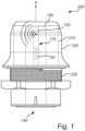
Fig. 1 diagrammatically illustrates acommunication device 200 comprising a communication unit 100 (schematically indicated by dashed lines) according to an embodiment of the present invention. Thecommunication unit 100 comprises acarrier substrate 110, e.g. a printed circuit board (PCB). Thecarrier substrate 110 is arranged in parallel with a longitudinal axis A of thecommunication unit 100, i.e. thecarrier substrate 110 is arranged in a standing (upright) position within thecommunication unit 100. Thecommunication unit 100 further comprises at least onetransceiver 120 for transmitting and receiving signals, comprising at least one antenna. Thetransceiver 120 and/or antenna is arranged on an (upper) end portion of thecarrier substrate 110. Thecommunication unit 100 further comprises at least one converter 130 (schematically indicated) which is arranged or configured to convert between different communication protocols. Anelectrical interface 140 is provided at a bottom end portion of thecommunication unit 100. It will be appreciated that the relatively large diameter of thecommunication unit 100 of the present invention allows the electrical interface(s) 140 to be standardized. For example, the electrical interfaces(s) 140 may comprise one or more so called D-subminiature connectors (D-sub), and relatively small contacts, which consequently may be expensive and/or complex, may be avoided. - The
communication unit 100 is configured to establish a connection between thecommunication unit 100 and at least one first electronic unit (not shown), e.g. via theelectrical interface 140, and between thecommunication unit 100 and at least one second electronic unit (not shown) via thetransceiver 120. Based on this connection, thecommunication unit 100 is further configured to establish a communication between the at least one first electronic unit communicable via a first protocol and/or format and the at least one second electronic unit communicable via a second protocol and/or format via theconverter 130. - The
communication device 200 comprises ahousing 210 arranged to at least partially accommodate thecommunication unit 100. Thecarrier substrate 110 may be attached to thehousing 210 via at least one resilient element (not shown) for preventing damages to thecarrier substrate 110 caused by (intentional or unintentional) shocks, impacts, or the like, of thecommunication device 200. The resilient element may e.g. be a shock absorber made of rubber. - The
communication device 200 further comprises acap 220 attached to thehousing 210. Thecap 220, which inFig. 1 is schematically shown in the form of a hat or helmet, is arranged to at least partially cover thehousing 210. - Furthermore, the
communication device 200 comprises a threadedconnection 225 for connecting a first (upper) portion of thecommunication device 200 with a second (lower) portion of thecommunication device 200. -
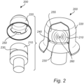
Fig. 2 diagrammatically illustrates thecommunication device 200 according toFig. 1 which further comprises thecap 220 attached to thehousing 210. Thecap 220 may have substantially any form, anddifferent caps 220 may furthermore be made of different materials (e.g. plastic) dependent on the environment which thecommunication device 200 is intended for. Thecaps 220 may also have different colors such that they are easily identified in case two ormore communication devices 200 are provided in a communication system. - The
cap 220 may be attached to thehousing 210 via at least one snap connection. The snap connection of thecommunication device 200 as exemplified has anannual groove 230 in thehousing 210 and anannual flange 240 in thecap 220, but it will be appreciated that the opposite relationship is also feasible. Theannual flange 240 is configured to project into theannual groove 230. It will be appreciated that thecap 220 may be mounted to thehousing 210 by a simple push, whereby theflange 240 becomes attached to thegroove 230. Thecap 220 may be rotated on thehousing 210, and hereby impedes (intentional or unintentional) attempts of unscrewing and/or removing thecommunication unit 220. Theannual flange 240 may furthermore comprise a plurality oftabs 250, and the fixation of thecap 220 to thehousing 210 may be made with the aid of a tool. Moreover, thecap 220 of thecommunication device 200 may be configured to provide anair gap 255 between thecap 220 and thehousing 210 for isolation purposes. It will be appreciated that the provision of theair gap 255 may be particularly advantageous in case thecommunication device 200 is arranged in a warm and/or sun-exposed environment. - The
communication device 200 ofFig. 2 may further comprise at least onesensor 260 arranged in thehousing 210, wherein thesensor 260 is configured to detect damage to thehousing 210 and/orcap 220. For example, thesensor 260 may be a light-sensitive sensor comprising at least one photo-diode. In case thehousing 210 and/orcap 220 is damaged (e.g. cracked), the light-sensitive sensor may detect a light intensity due to sunlight and/or artificial light entering thehousing 210. For example, if the light-sensitive sensor registers a light-intensity above a predetermined threshold, it may alert an operator that thecommunication device 200 has been damaged. -
Fig. 3 diagrammatically illustrates acommunication system 300 according to an embodiment of the present invention. Thecommunication system 300 comprises acabinet 310 and at least one firstelectronic unit 320 communicable via a first protocol arranged in thecabinet 310. Thecommunication system 300 further comprises at least one secondelectronic unit 330 communicable via a second protocol arranged outside thecabinet 310. Furthermore, thecommunication system 300 comprises acommunication device 200 as previously described for establishing a connection between the first and secondelectronic units electronic units communication device 200 and the firstelectronic unit 320 are connected by anelectrical interface 325, comprising one or more wires. As an alternative, the connection may be wireless. Thecommunication device 200 may convert the wired communication format and/or protocol of the firstelectronic unit 320 to a wireless communication format and/or protocol of the secondelectronic unit 330, or vice versa, for establishing communication between the first and secondelectronic units communication unit 200 may furthermore convert a wireless, first protocol communication format of at least one (third)electronic unit 410 to a wireless, second protocol communication format of at least one (second)electronic unit 330, for establishing communication between the second and thirdelectronic units communication unit 200 may act as a wireless access point between the at least one (third)electronic unit 410 and the at least one (second)electronic unit 330. Furthermore, thecommunication unit 200 may act as a protocol converter between one or more of the at least one (first)electronic unit 320, the at least one (second)electronic unit 330 and the at least one (third)electronic unit 410. - The
cabinet 310 comprises ahole 335 in which thecommunication device 200 is arranged. Thehole 335 may for example be completely round, as exemplified by ahole 345. A first (upper)portion 270 of thecommunication device 200 is connected to a second (lower)portion 280 of thecommunication device 200 via a threaded connection such that projecting flanges of the first andsecond portions hole 335 of the wall of thecabinet 310. Thecommunication device 200 has a relatively large diameter which results in a distribution of pressure to the edges of thecommunication device 200. Furthermore, the material of the flanges of the first andsecond portions communication device 200 are relatively thick, which contributes to an increased strength and robustness of thecommunication device 200. Moreover, the nut of thecommunication device 200 may be relatively large, which even further facilitates the mounting of thecommunication device 200. - The
communication device 200 may comprise a resilient seal member (not shown) for providing a sealing between thecommunication device 200 and thecabinet 310. The resilient seal member, which may be a rubber bushing or the like, may provide IP 65 sealing between thefirst portion 270 of thecommunication device 200 from the outside environment. Thesecond portion 280 of thecommunication device 200 may be sealed from the interior of thecabinet 310 fulfilling IP 20 sealing. - The
hole 335 may furthermore be configured to receive thecommunication device 200 in a unique orientation of thecommunication device 200. For example, thehole 335 may take on one or more asymmetric shapes, such as a hole with a cut out or recess 340 or a hole with aflat portion 350. Thecommunication device 200 may be shaped accordingly, such that its form fit in thehole 335 leads to a unique orientation of thecommunication device 200. - In
Fig. 3 , the transceiver of thecommunication unit 200 protrudes (projects) from the wall into the exterior of thecabinet 310 for establishing a connection with the secondelectronic unit 330 arranged outside thecabinet 310. It will be appreciated that the communication between the transceiver and the secondelectronic unit 330 may be performed over networks such as 3G, WLAN, Bluetooth, etc. Due to this advantageous positioning of the transceiver/antenna of thecommunication unit 200 when the latter is arranged in thecabinet 310, an impaired transmission pattern and/or directivity of the transceiver/antenna is mitigated. It will be appreciated that the arrangement disclosed is particularly advantageous in the case the material of thecabinet 310 is metal. - The invention has mainly been described above with reference to a few embodiments. However, as is readily appreciated by a person skilled in the art, other embodiments than the ones disclosed above are equally possible within the scope of the invention, as defined by the appended patent claims.
Claims (11)
- A communication system (300), comprisinga cabinet (310);at least one first electronic unit (320) communicable via a first communication protocol and arranged within said cabinet;at least one second electronic unit (330) communicable via a second communication protocol and arranged outside said cabinet; anda communication device (200), comprisinga communication unit (100), comprisinga carrier substrate (110),at least one transceiver (120) comprising at least one antenna,wherein said at least one transceiver is arranged on a carrier substrate, and
at least one converter (130) arranged to convert between different communication protocols,wherein said communication unit is configured to establish a connection between said communication unit and at least one first electronic unit, and between said communication unit and at least one second electronic unit via said at least one transceiver,and wherein said communication unit, based on said connection, is further configured to establish a communication between at least one first electronic unit communicable via a first communication protocol and at least one second electronic unit communicable via a second communication protocol via said at least one converter,wherein said communication device is configured for arrangement at least partially within a wall of the cabinet, and wherein at least one of said at least one transceiver is configured to protrude from the wall into the exterior of the cabinet for establishing a connection with said at least one second electronic unit arranged outside said cabinet,and wherein said communication device further comprisesa housing (210) arranged to at least partially accommodate said communication unit, anda cap (220) attached to said housing with the aid of a tool and arranged to at least partially cover said housing protruding from the wall into the exterior of the cabinet, whereby the cap contributes to the tamper resistance as well as the anti-theft protection of the communication device,wherein said housing and said cap comprise reciprocal snap connection elements in the form of at least one annual groove (230) and at least one annual flange (240) configured to project into said at least one annual groove. - The communication system according to claim 1, wherein said at least one converter is arranged to convert between wired and wireless communications, and wherein said communication unit, based on said connection, is further configured to establish a communication between at least one first electronic unit communicable via at least one wired connection and at least one second electronic unit communicable via at least one wireless connection via said at least one converter.
- The communication system according to claims 1 or 2, further comprisingat least one electrical interface (140),wherein said communication unit is configured to establish a connection between said communication unit and at least one first electronic unit via said at least one electrical interface, and between said communication unit and at least one second electronic unit via said at least one transceiver, respectively.
- The communication system according to any one of the preceding claims, wherein said carrier substrate is arranged in parallel with a longitudinal axis (A) of said communication unit, and wherein said at least one antenna is arranged on an end portion of said carrier substrate.
- The communication system according to any one of the preceding claims, wherein said carrier substrate is attached to said housing via at least one resilient element.
- The communication system as claimed in any one of the preceding claims, wherein said cap is configured to provide an air gap (255) between said cap and said housing.
- The communication system as claimed in any one of the preceding claims, further comprising at least one sensor (260) arranged in said housing, wherein said at least one sensor is configured to detect damage to said housing.
- The communication system as claimed in claim 7, wherein said at least one sensor is a light-sensitive sensor comprising at least one photodiode.
- The communication system according to any one of the preceding claims, wherein said cap comprises at least one resilient seal member configured to provide a sealing between said cap and the cabinet.
- The communication system according to any one of the preceding claims, further comprising
a hole (335) in a wall of said cabinet, wherein said hole is configured to receive said communication device in a unique orientation of said communication device. - A method for establishing a communication between electronic units communicable via different communication protocols, comprisingproviding at least one first electronic unit communicable via a first communication protocol and at least one second electronic unit communicable via a second communication protocol;providing a communication system according to any one of the preceding claims;establishing a connection between said communication unit and said at least one first electronic unit and between said communication unit and said at least one second electronic unit, respectively; andestablishing a communication between said at least one first electronic unit and said at least one second electronic unit based on said connection.
Applications Claiming Priority (1)
| Application Number | Priority Date | Filing Date | Title |
|---|---|---|---|
| SE1551508A SE540510C2 (en) | 2015-11-20 | 2015-11-20 | Device, system and method for communication between electronic units communicable via different communication formats |
Publications (2)
| Publication Number | Publication Date |
|---|---|
| EP3185662A1 EP3185662A1 (en) | 2017-06-28 |
| EP3185662B1 true EP3185662B1 (en) | 2023-04-26 |
Family
ID=57485296
Family Applications (1)
| Application Number | Title | Priority Date | Filing Date |
|---|---|---|---|
| EP16199784.6A Active EP3185662B1 (en) | 2015-11-20 | 2016-11-21 | Communication device |
Country Status (2)
| Country | Link |
|---|---|
| EP (1) | EP3185662B1 (en) |
| SE (1) | SE540510C2 (en) |
Families Citing this family (1)
| Publication number | Priority date | Publication date | Assignee | Title |
|---|---|---|---|---|
| DE102018111111A1 (en) | 2018-05-09 | 2019-11-14 | Phoenix Contact Gmbh & Co. Kg | Cable connector for transmitting electrical signals |
Family Cites Families (1)
| Publication number | Priority date | Publication date | Assignee | Title |
|---|---|---|---|---|
| US5877703A (en) * | 1997-08-12 | 1999-03-02 | Badger Meter, Inc. | Utility meter transmitter assembly for subsurface installations |
-
2015
- 2015-11-20 SE SE1551508A patent/SE540510C2/en unknown
-
2016
- 2016-11-21 EP EP16199784.6A patent/EP3185662B1/en active Active
Also Published As
| Publication number | Publication date |
|---|---|
| EP3185662A1 (en) | 2017-06-28 |
| SE540510C2 (en) | 2018-09-25 |
| SE1551508A1 (en) | 2017-05-21 |
Similar Documents
| Publication | Publication Date | Title |
|---|---|---|
| RU2419926C2 (en) | Wireless field device with antenna for industrial locations | |
| US7312716B2 (en) | Wireless communication using an intrinsically safe design for use in a hazardous area | |
| RU2467373C2 (en) | Improved form factor and electromagnetic interference protection for process device wireless adapters | |
| US11252803B2 (en) | Operating device with staggered protection circuits against overvoltage and overcurrent and antenna for driving intelligent lamps and lighting appliances | |
| RU2420832C2 (en) | Field device of production process with energy limited battery assembly | |
| EP2792078B1 (en) | Providing remote access to a wireless communication device for controlling a device in a housing | |
| US9543712B2 (en) | Intrinsically safe wireless dongle for a field device | |
| US20070198224A1 (en) | Adjustable industrial antenna mount | |
| EP3048740B1 (en) | Antenna module, wireless device, and field-device control system | |
| JP2013504259A (en) | Wire harness for field devices used in hazardous locations | |
| CA2290927C (en) | Transmitter housing | |
| EP3185662B1 (en) | Communication device | |
| US7787921B2 (en) | Link coupled antenna system on a field device having a grounded housing | |
| US11051419B2 (en) | Chassis for a circuit assembly | |
| JP4838050B2 (en) | Wireless LAN explosion-proof repeater, explosion-proof switching hub, explosion-proof wireless communication means, switching hub with explosion-proof wireless communication means, and communication system in hazardous areas | |
| JP4469288B2 (en) | Wireless LAN explosion-proof repeater and communication system in hazardous area | |
| RU2000124067A (en) | COMPUTER NETWORK WITH TERMINAL DATA OR COMMUNICATION SYSTEMS | |
| US20220326672A1 (en) | Automation field device | |
| CN108965116B (en) | Wireless gateway system and communication method thereof | |
| US6354857B1 (en) | Transmitter housing | |
| JP4273995B2 (en) | Wireless circuit of home electrical equipment network control information terminal equipment | |
| US20210232117A1 (en) | Rtu addon | |
| CN113193879B (en) | Explosion-proof industrial data transmission device based on multiple interfaces and data transmission method thereof | |
| CN220693324U (en) | Outdoor pickup equipment | |
| CN207505024U (en) | A kind of industrial switch based on video code flow technology |
Legal Events
| Date | Code | Title | Description |
|---|---|---|---|
| PUAI | Public reference made under article 153(3) epc to a published international application that has entered the european phase |
Free format text: ORIGINAL CODE: 0009012 |
|
| STAA | Information on the status of an ep patent application or granted ep patent |
Free format text: STATUS: THE APPLICATION HAS BEEN PUBLISHED |
|
| AK | Designated contracting states |
Kind code of ref document: A1 Designated state(s): AL AT BE BG CH CY CZ DE DK EE ES FI FR GB GR HR HU IE IS IT LI LT LU LV MC MK MT NL NO PL PT RO RS SE SI SK SM TR |
|
| AX | Request for extension of the european patent |
Extension state: BA ME |
|
| STAA | Information on the status of an ep patent application or granted ep patent |
Free format text: STATUS: REQUEST FOR EXAMINATION WAS MADE |
|
| 17P | Request for examination filed |
Effective date: 20171207 |
|
| RBV | Designated contracting states (corrected) |
Designated state(s): AL AT BE BG CH CY CZ DE DK EE ES FI FR GB GR HR HU IE IS IT LI LT LU LV MC MK MT NL NO PL PT RO RS SE SI SK SM TR |
|
| STAA | Information on the status of an ep patent application or granted ep patent |
Free format text: STATUS: EXAMINATION IS IN PROGRESS |
|
| 17Q | First examination report despatched |
Effective date: 20210428 |
|
| STAA | Information on the status of an ep patent application or granted ep patent |
Free format text: STATUS: EXAMINATION IS IN PROGRESS |
|
| GRAP | Despatch of communication of intention to grant a patent |
Free format text: ORIGINAL CODE: EPIDOSNIGR1 |
|
| STAA | Information on the status of an ep patent application or granted ep patent |
Free format text: STATUS: GRANT OF PATENT IS INTENDED |
|
| INTG | Intention to grant announced |
Effective date: 20221130 |
|
| GRAS | Grant fee paid |
Free format text: ORIGINAL CODE: EPIDOSNIGR3 |
|
| GRAA | (expected) grant |
Free format text: ORIGINAL CODE: 0009210 |
|
| STAA | Information on the status of an ep patent application or granted ep patent |
Free format text: STATUS: THE PATENT HAS BEEN GRANTED |
|
| AK | Designated contracting states |
Kind code of ref document: B1 Designated state(s): AL AT BE BG CH CY CZ DE DK EE ES FI FR GB GR HR HU IE IS IT LI LT LU LV MC MK MT NL NO PL PT RO RS SE SI SK SM TR |
|
| REG | Reference to a national code |
Ref country code: GB Ref legal event code: FG4D |
|
| REG | Reference to a national code |
Ref country code: CH Ref legal event code: EP |
|
| REG | Reference to a national code |
Ref country code: DE Ref legal event code: R096 Ref document number: 602016079017 Country of ref document: DE |
|
| REG | Reference to a national code |
Ref country code: AT Ref legal event code: REF Ref document number: 1563792 Country of ref document: AT Kind code of ref document: T Effective date: 20230515 |
|
| REG | Reference to a national code |
Ref country code: IE Ref legal event code: FG4D |
|
| REG | Reference to a national code |
Ref country code: LT Ref legal event code: MG9D |
|
| REG | Reference to a national code |
Ref country code: NL Ref legal event code: MP Effective date: 20230426 |
|
| REG | Reference to a national code |
Ref country code: AT Ref legal event code: MK05 Ref document number: 1563792 Country of ref document: AT Kind code of ref document: T Effective date: 20230426 |
|
| PG25 | Lapsed in a contracting state [announced via postgrant information from national office to epo] |
Ref country code: NL Free format text: LAPSE BECAUSE OF FAILURE TO SUBMIT A TRANSLATION OF THE DESCRIPTION OR TO PAY THE FEE WITHIN THE PRESCRIBED TIME-LIMIT Effective date: 20230426 |
|
| PG25 | Lapsed in a contracting state [announced via postgrant information from national office to epo] |
Ref country code: SE Free format text: LAPSE BECAUSE OF FAILURE TO SUBMIT A TRANSLATION OF THE DESCRIPTION OR TO PAY THE FEE WITHIN THE PRESCRIBED TIME-LIMIT Effective date: 20230426 Ref country code: PT Free format text: LAPSE BECAUSE OF FAILURE TO SUBMIT A TRANSLATION OF THE DESCRIPTION OR TO PAY THE FEE WITHIN THE PRESCRIBED TIME-LIMIT Effective date: 20230828 Ref country code: NO Free format text: LAPSE BECAUSE OF FAILURE TO SUBMIT A TRANSLATION OF THE DESCRIPTION OR TO PAY THE FEE WITHIN THE PRESCRIBED TIME-LIMIT Effective date: 20230726 Ref country code: ES Free format text: LAPSE BECAUSE OF FAILURE TO SUBMIT A TRANSLATION OF THE DESCRIPTION OR TO PAY THE FEE WITHIN THE PRESCRIBED TIME-LIMIT Effective date: 20230426 Ref country code: AT Free format text: LAPSE BECAUSE OF FAILURE TO SUBMIT A TRANSLATION OF THE DESCRIPTION OR TO PAY THE FEE WITHIN THE PRESCRIBED TIME-LIMIT Effective date: 20230426 |
|
| PG25 | Lapsed in a contracting state [announced via postgrant information from national office to epo] |
Ref country code: RS Free format text: LAPSE BECAUSE OF FAILURE TO SUBMIT A TRANSLATION OF THE DESCRIPTION OR TO PAY THE FEE WITHIN THE PRESCRIBED TIME-LIMIT Effective date: 20230426 Ref country code: PL Free format text: LAPSE BECAUSE OF FAILURE TO SUBMIT A TRANSLATION OF THE DESCRIPTION OR TO PAY THE FEE WITHIN THE PRESCRIBED TIME-LIMIT Effective date: 20230426 Ref country code: LV Free format text: LAPSE BECAUSE OF FAILURE TO SUBMIT A TRANSLATION OF THE DESCRIPTION OR TO PAY THE FEE WITHIN THE PRESCRIBED TIME-LIMIT Effective date: 20230426 Ref country code: LT Free format text: LAPSE BECAUSE OF FAILURE TO SUBMIT A TRANSLATION OF THE DESCRIPTION OR TO PAY THE FEE WITHIN THE PRESCRIBED TIME-LIMIT Effective date: 20230426 Ref country code: IS Free format text: LAPSE BECAUSE OF FAILURE TO SUBMIT A TRANSLATION OF THE DESCRIPTION OR TO PAY THE FEE WITHIN THE PRESCRIBED TIME-LIMIT Effective date: 20230826 Ref country code: HR Free format text: LAPSE BECAUSE OF FAILURE TO SUBMIT A TRANSLATION OF THE DESCRIPTION OR TO PAY THE FEE WITHIN THE PRESCRIBED TIME-LIMIT Effective date: 20230426 Ref country code: GR Free format text: LAPSE BECAUSE OF FAILURE TO SUBMIT A TRANSLATION OF THE DESCRIPTION OR TO PAY THE FEE WITHIN THE PRESCRIBED TIME-LIMIT Effective date: 20230727 |
|
| PG25 | Lapsed in a contracting state [announced via postgrant information from national office to epo] |
Ref country code: FI Free format text: LAPSE BECAUSE OF FAILURE TO SUBMIT A TRANSLATION OF THE DESCRIPTION OR TO PAY THE FEE WITHIN THE PRESCRIBED TIME-LIMIT Effective date: 20230426 |
|
| PG25 | Lapsed in a contracting state [announced via postgrant information from national office to epo] |
Ref country code: SK Free format text: LAPSE BECAUSE OF FAILURE TO SUBMIT A TRANSLATION OF THE DESCRIPTION OR TO PAY THE FEE WITHIN THE PRESCRIBED TIME-LIMIT Effective date: 20230426 |
|
| REG | Reference to a national code |
Ref country code: DE Ref legal event code: R097 Ref document number: 602016079017 Country of ref document: DE |
|
| PG25 | Lapsed in a contracting state [announced via postgrant information from national office to epo] |
Ref country code: SM Free format text: LAPSE BECAUSE OF FAILURE TO SUBMIT A TRANSLATION OF THE DESCRIPTION OR TO PAY THE FEE WITHIN THE PRESCRIBED TIME-LIMIT Effective date: 20230426 Ref country code: SK Free format text: LAPSE BECAUSE OF FAILURE TO SUBMIT A TRANSLATION OF THE DESCRIPTION OR TO PAY THE FEE WITHIN THE PRESCRIBED TIME-LIMIT Effective date: 20230426 Ref country code: RO Free format text: LAPSE BECAUSE OF FAILURE TO SUBMIT A TRANSLATION OF THE DESCRIPTION OR TO PAY THE FEE WITHIN THE PRESCRIBED TIME-LIMIT Effective date: 20230426 Ref country code: EE Free format text: LAPSE BECAUSE OF FAILURE TO SUBMIT A TRANSLATION OF THE DESCRIPTION OR TO PAY THE FEE WITHIN THE PRESCRIBED TIME-LIMIT Effective date: 20230426 Ref country code: DK Free format text: LAPSE BECAUSE OF FAILURE TO SUBMIT A TRANSLATION OF THE DESCRIPTION OR TO PAY THE FEE WITHIN THE PRESCRIBED TIME-LIMIT Effective date: 20230426 Ref country code: CZ Free format text: LAPSE BECAUSE OF FAILURE TO SUBMIT A TRANSLATION OF THE DESCRIPTION OR TO PAY THE FEE WITHIN THE PRESCRIBED TIME-LIMIT Effective date: 20230426 |
|
| PLBE | No opposition filed within time limit |
Free format text: ORIGINAL CODE: 0009261 |
|
| STAA | Information on the status of an ep patent application or granted ep patent |
Free format text: STATUS: NO OPPOSITION FILED WITHIN TIME LIMIT |
|
| 26N | No opposition filed |
Effective date: 20240129 |
|
| PG25 | Lapsed in a contracting state [announced via postgrant information from national office to epo] |
Ref country code: SI Free format text: LAPSE BECAUSE OF FAILURE TO SUBMIT A TRANSLATION OF THE DESCRIPTION OR TO PAY THE FEE WITHIN THE PRESCRIBED TIME-LIMIT Effective date: 20230426 |