EP3185654B1 - Method for allocating participants which can be controlled via a wireless communication network to at least one control transmitter - Google Patents
Method for allocating participants which can be controlled via a wireless communication network to at least one control transmitter Download PDFInfo
- Publication number
- EP3185654B1 EP3185654B1 EP16196842.5A EP16196842A EP3185654B1 EP 3185654 B1 EP3185654 B1 EP 3185654B1 EP 16196842 A EP16196842 A EP 16196842A EP 3185654 B1 EP3185654 B1 EP 3185654B1
- Authority
- EP
- European Patent Office
- Prior art keywords
- transmitter
- receivers
- stationary
- control unit
- portable
- Prior art date
- Legal status (The legal status is an assumption and is not a legal conclusion. Google has not performed a legal analysis and makes no representation as to the accuracy of the status listed.)
- Active
Links
- 238000004891 communication Methods 0.000 title claims description 66
- 238000000034 method Methods 0.000 title claims description 32
- 230000005540 biological transmission Effects 0.000 claims description 5
- 230000001960 triggered effect Effects 0.000 claims description 2
- 238000009434 installation Methods 0.000 description 5
- 230000008901 benefit Effects 0.000 description 2
- 230000008569 process Effects 0.000 description 2
- 230000004913 activation Effects 0.000 description 1
- 230000004397 blinking Effects 0.000 description 1
- 230000008859 change Effects 0.000 description 1
- 239000003086 colorant Substances 0.000 description 1
- 238000010276 construction Methods 0.000 description 1
- 230000006870 function Effects 0.000 description 1
- 230000009467 reduction Effects 0.000 description 1
- 230000000717 retained effect Effects 0.000 description 1
Images

Classifications
-
- H04B5/72—
-
- H—ELECTRICITY
- H04—ELECTRIC COMMUNICATION TECHNIQUE
- H04W—WIRELESS COMMUNICATION NETWORKS
- H04W84/00—Network topologies
- H04W84/18—Self-organising networks, e.g. ad-hoc networks or sensor networks
- H04W84/20—Master-slave selection or change arrangements
-
- H—ELECTRICITY
- H05—ELECTRIC TECHNIQUES NOT OTHERWISE PROVIDED FOR
- H05B—ELECTRIC HEATING; ELECTRIC LIGHT SOURCES NOT OTHERWISE PROVIDED FOR; CIRCUIT ARRANGEMENTS FOR ELECTRIC LIGHT SOURCES, IN GENERAL
- H05B47/00—Circuit arrangements for operating light sources in general, i.e. where the type of light source is not relevant
- H05B47/10—Controlling the light source
- H05B47/175—Controlling the light source by remote control
- H05B47/19—Controlling the light source by remote control via wireless transmission
-
- H05B47/1965—
-
- G—PHYSICS
- G08—SIGNALLING
- G08C—TRANSMISSION SYSTEMS FOR MEASURED VALUES, CONTROL OR SIMILAR SIGNALS
- G08C17/00—Arrangements for transmitting signals characterised by the use of a wireless electrical link
- G08C17/02—Arrangements for transmitting signals characterised by the use of a wireless electrical link using a radio link
-
- G—PHYSICS
- G08—SIGNALLING
- G08C—TRANSMISSION SYSTEMS FOR MEASURED VALUES, CONTROL OR SIMILAR SIGNALS
- G08C2201/00—Transmission systems of control signals via wireless link
- G08C2201/20—Binding and programming of remote control devices
Definitions
- the invention relates to a method for assigning subscribers (receivers) which can be controlled via a wireless communication network to at least one operator transmitter arranged outside of possible short-range communication with the receivers, by means of which operator transmitter, after the assignment has been made, the receivers assigned to it can be controlled, the receivers being set up to enter into a network link by means of a wireless short-range communication with a transmitter after being asked to do so.
- the invention further relates to a wireless communication network.
- wireless communication networks are used to control one or more receivers via an operator transmitter.
- a wireless communication link is preferably used in order to control one or more receivers from an operator transmitter.
- any actuator can be regarded as a receiver in this version.
- Lamps and lights may be mentioned as examples of actuators.
- lamps and luminaires which have an integrated network radio and network control element so that they can be controlled by an operating transmitter via the wireless communication link. Such lamps and lights can be provided for emitting colored light.
- lamps and luminaires are typically equipped with light-emitting diodes (LED) for this purpose and are driven by a corresponding ballast.
- LED light-emitting diodes
- Lamps and lights can be permanently installed in the building or can also be part of other furnishings.
- the network has at least one operator transmitter. This is arranged on the wall side, so that you can follow the usual habits when Entering or leaving a room by actuating the wall switch designed as a control transmitter can switch the room lighting or part of it on and off.
- a standard with which this can be carried out is, for example, the ZigBee Light Link Standard from the ZigBee Alliance, Inc.
- This standard includes the "Touchlink” linking routine. If this routine is received in the context of short-range communication by a lamp or luminaire addressed thereby, the transmitter emitting this routine and the subscriber receiving this routine are linked to one another as part of a common communication network. This also includes that the subscriber addressed by this routine transmits its network parameters necessary for communication in the network to the transmitter issuing the "touchlink" routine.
- this short-range communication will be limited to 1 to 1.5 m or less in order to be able to individually link with individual receivers.
- the establishment of the close range depends on the desired design and can also be less than 0.5 m. Close-range communications are also possible, which still work at a distance of three meters. Since it is cumbersome or with lamps or luminaires of this type permanently installed in the building, it is not possible to bring them in the vicinity for the purpose of linking to a wall-mounted operator transmitter, wall-mounted operator transmitters are used which are not permanently installed in the building, but for the purpose of one Assignment of the receivers to be controlled by these can be removed or removed from a holder.
- such a wall-mounted operator transmitter is removed from its wall-side holder and brought to link it with the lamps or lights to be controlled by it, in each case in the vicinity thereof, in order then to carry out the above-described link as part of a short-range communication to be able to.
- This not only allows an assignment of receivers to such a wall-mounted operating transmitter when newly set up, but also a change in the assignment of the receivers to be controlled by setting up a new network.
- DE 697 34 569 T2 discloses a method for establishing a wireless network.
- the method described in this prior art is used to program network nodes. In a first step, these were physically placed. In a second step, an address is programmed for each node using a wireless installation device. Information regarding the physical placement of such a node and the address assigned to it is transmitted to a control node - a building computer. In addition to the address, the node receives all necessary standard settings when programming. One lighting module or several lighting modules are assigned to each node. How the lighting modules are assigned to the respective node is not described in this prior art.
- WO 2015/104248 A1 discloses a tablet PC-based picking tool for assigning actuators located in a building, for example lights (devices) and sensors, such as buttons (control devices).
- actuators located in a building, for example lights (devices) and sensors, such as buttons (control devices).
- all the controllable devices and control devices that are within range are collected with a portable control unit and then manually linked to one another so that the receivers linked to a control unit can then be controlled by it.
- a service transmitter can be assigned (picked) to a service transmitter, in particular also permanently installed on the building side, it must be accepted that due to the necessary portability of the service transmitter restrictions regarding the design options are accepted Need to become. If an actuator actuation in a room, for example the room lighting, is to be operated from several points, since the room has several entrances and exits, the assignment of the participants to be controlled must be made individually with each operator transmitter.
- the invention is therefore based on the object of designing a method of the type mentioned at the outset and a wireless communication network comprising a control transmitter and one or more actuators to be controlled by it, in such a way that not only in the design-oriented configuration of a wall-mounted operator transmitter, fewer restrictions have to be accepted, but that the assignment procedure to the individual operator transmitters is simplified even if there are several operator transmitters mounted on the wall.
- a method according to claim 1 and a wireless network according to claim 12 are provided.
- the method-related problem is solved according to the invention by a generic assignment method mentioned at the outset, in which short-range communication is only possible in a short range of a few decimeters and in a first step with a portable control unit designed as a transmitter, the network parameters of those necessary for its control Receivers can be collected by linking them to the portable control unit via the short-range communication, which are to be assigned to the at least one stationary control transmitter, and in a subsequent step the list of the collected and to be assigned to the stationary control transmitter with their network parameters from the portable control panel to the Operating transmitter is transmitted via short-range communication, so that the receiver assigned to it can then be controlled by the stationary operating transmitter.
- the communication network-related object is achieved by a wireless communication network for performing the aforementioned method with at least one stationary operating transmitter, with receivers that can be controlled by this and with a portable control unit designed as a transmitter, which aforementioned participants of the communication network are designed at least for the purpose of assigning receivers to the at least one stationary operator transmitter using short-range communication, and the portable control unit for creating an assignment of serves receivers to be controlled by the stationary operating transmitter.
- a portable control unit is used, with which the network parameters necessary for controlling a receiver are collected by all those receivers (actuators) that are to be controlled by an operating transmitter, which is arranged in a stationary manner on the wall.
- a link is first created between a portable control unit designed as a transmitter and the desired receivers.
- the link created in this way to one or more receivers is transferred to a stationary operating transmitter, so that those receivers that are part of the list of receivers transmitted from the portable operating unit to the stationary operating transmitter can then be controlled by the stationary operating transmitter.
- an additional portable control unit also allows the structure of a stationary control transmitter to be simplified if it is designed or is designed to control different receivers or groups of receivers independently of one another. Such a grouping can be carried out by the portable control panel, so that the process of such an assignment has to be assigned to the portable control panel and not necessarily to the stationary operator transmitter. Of course this is also possible.
- the portable control panel there is therefore the possibility of programming the stationary control transmitter, so that the latter does not necessarily have to have the necessary resources.
- the portable control panel is used to specify how to transfer a recipient list from the portable control panel to the stationary control panel with a recipient list already stored in the stationary control panel or individual recipients from it is to be dealt with. It is possible that when a recipient list is transmitted, a recipient list that may be present in the stationary operating transmitter is overwritten, and the newly transmitted recipient list thus replaces the previously existing one. In another mode, those receivers that are not yet included in the existing recipient list are added to an existing recipient list of the stationary service transmitter when a new recipient list is received.
- the portable operating unit receives a new recipient list in the recipient list of the stationary operating transmitter deleted those recipients from the existing recipient list that are also contained in the new recipient list.
- recipients not yet in the existing recipient list in the transmitted recipient list are included in the recipient list on the operator side.
- an additional portable control unit for the aforementioned purposes also has the advantage that it can also be used as a remote control. This is practical since the actuators can then also be controlled independently of the stationary operator transmitter or transmitters.
- This concept takes advantage of the fact that the portable control unit is designed as a transmitter anyway. In such a configuration of the portable control unit, it will be designed to enable operation in two transmission modes, on the one hand in a collection mode, which also includes the transmission of a recipient list to a stationary control transmitter, and on the other hand in a control mode (remote control mode) , in which the portable control unit can control the receivers listed in its recipient list.
- the transmitter works with a higher power in order to be able to reach the receivers to be controlled.
- the collected receiver data summarized in a receiver list
- This list of recipients is then retained, even if new receivers or their network parameters necessary for control are collected with the portable control panel. In this respect, this can also be seen as a security feature of this concept. Basically, this is not necessary in order to be able to carry out the method.
- the subscriber stationary operating transmitter, portable operating unit and receiver involved in the construction of the communication network will preferably be designed according to a common standard. It is advisable to use the ZigBee Light Link Standard from the ZigBee Alliance, Inc. It goes without saying that other specifications can also be used, via which a data exchange and thus a link between a transmitter and at least one receiver in the area of short-range communication is possible.
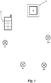
- FIG. 1 Several luminaires are installed in a room of a building, which is otherwise not shown in detail. Examples are in Figure 1 four lights L 1 to L 4 shown. These can be permanently installed on the ceiling or it can also be lamps of floor lamps or others Act lights. The lamps and lights are to be addressed as actuators in the context of a building installation system. As explained below, the lights L 1 to L 4 are integrated in a communication network and are thus, as it were, participants in the communication network. Since the lights L 1 to L 4 are controlled, they are receivers (command receivers) in the communication network. The lights L 1 to L 4 each have a network radio and network control element, so that they can be controlled on a wireless communication link, here: on a radio link.
- a wall-mounted control transmitter 1 is provided.
- the stationary control transmitter 1 is designed in the manner of a wall switch and can have one or more control elements 2, for example in the form of buttons, and / or a touch-sensitive display as the control element.
- control elements 2 for example in the form of buttons, and / or a touch-sensitive display as the control element.
- the stationary control transmitter 1 is shown with a button which represents the control element 2.
- the stationary control transmitter 1 must be linked to or with the lights L 1 to L 4 to be controlled. It is therefore necessary to marry the lights L 1 to L 4 to be controlled with the stationary operating transmitter 1 as actuators to the stationary operating transmitter 1 and to set up a communication network in this way.
- Both the stationary control transmitter 1 and the lights L 1 to L 4 are designed according to the ZigBee Light Link standard from the ZigBee Alliance, Inc.
- This specification not only includes a standardized routine for controlling the lights L 1 to L 4 , but also provides a linking routine.
- the actuator receiving this routine here: one or more of the lights L 1 to L 4 , provides the network parameters necessary for its control and, after completion of this routine, is responsible for this routine "Touchlink" sending transmitter married as network subscriber.
- This communication is only possible in a short range of a few decimeters in order to ensure that individual actuators can be introduced into a communication network independently of one another. It goes without saying that such a marriage can also be carried out with a different standard by means of short-range communication on a wireless link.
- the portable control unit 3 is a device which is designed in the manner of a remote control and can therefore be carried easily.
- the portable control unit 3 is brought up to each of these lights L 1 to L 4 to be assigned to the lights L 1 to L 4 to be controlled by the stationary control transmitter 1 and with each light L 1 to L 4 via the above-described short-range communication by exercising Routine "Touchlink" linked. It goes without saying that the portable control unit 3 is also designed to work in accordance with the ZigBee Light Link specification described above.
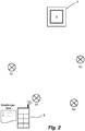
- FIG. 2 shows the portable control unit 3, how this has been brought close to the lamp L 2 to establish the "Touchlink” link.
- a link to the lamp L 1 was made beforehand.
- the portable operating unit 3 reads out the necessary network parameters of the respective light, here: the light L 2, and writes it to a temporary recipient list of the portable operating part 3.
- the lights L 1 to L 4 are spatially separated from one another to such an extent that a “touch link” routine triggered by the portable operating part 3 can only be received by one of the lights L 1 to L 4 .
- the "Touchlink” routine is used by several Receive actuators, a link between these multiple actuators is established with the portable control unit 3.
- the portable control unit 3 is brought to each lamp L 1 to L 4 which is to be controlled by the stationary control transmitter 1. In the present case, these are the lights L 1 to L 4 shown in the figures.
- Each link created is entered in the recipient list of the portable control unit 3.
- the recipient list is stored in a collection memory.
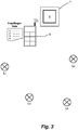
- the portable operating unit 3 is brought close to the stationary operating transmitter 1, to the extent that both components - portable control unit 3 and stationary control transmitter 1 - can communicate with each other via described short-range communication.
- the receiver list is transmitted from the portable operating part 3 to the stationary operating transmitter 1 (see Figure 3 ). In this way, the stationary operating transmitter 1 receives the network parameters necessary for activation from those lights L 1 to L 4 that have previously been collected by the portable operating part 3.
- the lights L 1 to L 4 can be controlled by the stationary operating transmitter 1 designed as a wall switch and can be switched on and off.
- the luminaires L 1 to L 4 have thus been picked at the wall switch designed as a stationary operating transmitter 1 without the now linked participants in the communication network being brought into close proximity to carry out individual short-range communication.
- the lights L 1 to L 4 can not only be switched on and off with the stationary control transmitter 1, but can also be operated in predetermined stages with a partial load.
- the stationary operator transmitter 1 is designed so that when a manual button is pressed that exceeds a specified period of time, the individual specified dimming levels are run through, and consequently the commands necessary for the dimming level to be controlled are sent in a time sequence. When the desired dimming level is reached, manual operation of the stationary control transmitter 1 is ended.
- the at least one stationary control transmitter 1 can also be used for color control.
- the recipient list is temporarily stored in the portable control unit 3 in the exemplary embodiment shown and is deleted when the portable control unit 3 is switched back to its collection mode, in which mode a link between the portable control unit 3 and the receiver (s) is performed by the routine "Touchlink""is brought about.
- the temporary recipient list can also be shifted into a receiver control memory.
- the portable control unit 3 can be switched to a control mode in which it can then be used as a remote control for controlling the receivers, here: the lights L 1 to L 4 , stored in the receiver control memory.
- the collection memory is cleared during this process.
- the receiver list stored in the receiver control memory can be copied or moved to the collection memory become.
- this list of receivers is transmitted to all stationary operating transmitters which are to control the lights L 1 to L 4 before the collection memory is reset.
- the communication network then set up to control the lights L 1 to L 4 can easily be expanded to include additional receivers.
- recipients registered in the recipient list of the stationary operating transmitter 1 can be deleted from this list.
- Adding one or more further receivers to the receiver list of the stationary operating transmitter 1 takes place in the same way as was described above when setting up the network.
- the stationary operating transmitter 1 is in a mode in which, when a new recipient list is received, those receivers from the newly received recipient list are entered into the existing recipient list that are not yet contained therein.
- a receiver present in the recipient list of the stationary operating transmitter 1 is removed, in that this is also part of a newly received recipient list.
- the portable control unit 3 In order to switch the portable control unit from one mode to the other or to use the portable control unit 3 as a remote control for controlling the lights L 1 to L 4 , it has several buttons (indicated in the figures).
- the portable control unit 3 also has a control functionality, for example to check which lights L 1 - L 4 are actually listed in the receiver list before transmitting a recipient list.
- a control functionality can be implemented, for example, via a button, the actuation of which controls the receivers contained in the recipient list for working in a control mode.
- Such a mode of operation can be implemented, for example, as a blinking. In this way it can be checked whether the desired recipients actually exist in the recipient list.
- the stationary control transmitter for such a wireless communication network can also be designed with several buttons. It is then possible to assign different control functions to different keys and thus, for example, to individual ones Luminaires L 1 to L 4 or a grouping of them in the control. It is also quite possible that such a stationary operating transmitter has several recipient lists or a recipient list divided into different groups, one recipient list or one group of the recipient list being assigned to a button. It can also be provided that the recipient list of the stationary operator transmitter is divided into groups, so that one or the other group or all of the receivers can be controlled depending on the desired control and thus on the key actuation carried out.
- Figure 4 shows a further stage of the communication network of the previous figures.
- a router 4 is implemented in this communication network.
- the router 4 has also been integrated into the communication network with the portable control unit 3, as has already been described for the stationary control transmitter 1.
- the lights L 1 to L 4 can thus also be controlled via the router 4.
- the router 4 itself can be controlled via a WLAN, for example from a smartphone or the like.
- scenes can be set in one or more receivers or groups of receivers via the stationary operator control of the transmitters. As already described for the above exemplary embodiment, these are then typically stored in each actuator involved in this scene. In the event that the recipient lists are stored in volatile memory in the one or more stationary operator transmitters, the link and the scene setting can easily be transferred from the actuators to the stationary operator transmitter again via the portable control unit after a power failure become.
- the described assignment method and the wireless communication network are suitable for controlling various actuators, the invention having been explained with the aid of lamps or lights as actuators.
- actuators can, for example, also be switchable intermediate plugs via which an actuator that is actually to be controlled, for example a floor lamp or the like, is to be controlled.
Description
Die Erfindung betrifft ein Verfahren zum Zuordnen von über ein drahtloses Kommunikationsnetzwerk ansteuerbaren Teilnehmern (Empfängern) zu zumindest einem außerhalb einer möglichen Nahbereichskommunikation mit den Empfängern angeordneten Bediensender, durch welchen Bediensender nach erfolgter Zuordnung die ihm zugeordneten Empfänger angesteuert werden können wobei die Empfänger eingerichtet sind, um eine Netzwerkverknüpfung mittels einer drahtlosen Nahbereichskommunikation nach zuvor erfolgter Aufforderung mit einem Sender einzugehen. Ferner betrifft die Erfindung ein drahtloses Kommunikationsnetzwerk.The invention relates to a method for assigning subscribers (receivers) which can be controlled via a wireless communication network to at least one operator transmitter arranged outside of possible short-range communication with the receivers, by means of which operator transmitter, after the assignment has been made, the receivers assigned to it can be controlled, the receivers being set up to enter into a network link by means of a wireless short-range communication with a transmitter after being asked to do so. The invention further relates to a wireless communication network.
Im Bereich der Gebäudeinstallation werden drahtlose Kommunikationsnetzwerke eingesetzt, um über diese seitens eines Bediensenders ein oder mehrere Empfänger anzusteuern. Gerade bei nachträglichen Installationen oder bei solchen Installationen, die ab und zu geändert werden sollen, bedient man sich bevorzugt einer drahtlosen Kommunikationsstrecke, um von einem Bediensender ein oder mehrere Empfänger anzusteuern. Als Empfänger kann im Rahmen dieser Ausführung grundsätzlich jeder Aktor angesehen sein. Lampen und Leuchten mögen beispielhaft als Aktoren genannt sein. Es sind beispielsweise Lampen und Leuchten bekannt, die ein integriertes Netzwerkfunk- und Netzwerksteuerglied aufweisen, damit diese über die drahtlose Kommunikationsstrecke von einem Bediensender angesteuert werden können. Derartige Lampen und Leuchten können zur Abgabe von farbigem Licht vorgesehen sein. Typischerweise sind Lampen und Leuchten heute zu diesem Zweck mit Leuchtdioden (LED) bestückt und werden mit einem entsprechenden Vorschaltgerät angetrieben. Lampen und Leuchten können gebäudeseitig fest installiert oder auch Teil anderer Einrichtungsgegenstände sein. Neben diesen Empfängern verfügt das Netzwerk über zumindest einen Bediensender. Dieser ist wandseitig angeordnet, damit man, den herkömmlichen Gewohnheiten folgend, beim Eintreten in einen Raum oder beim Verlassen desselben durch Betätigung des als Bediensender ausgelegten Wandschalters die Raumbeleuchtung oder einen Teil derselben ein- und ausschalten kann.In the field of building installation, wireless communication networks are used to control one or more receivers via an operator transmitter. Especially in subsequent installations or in those installations that are to be changed from time to time, a wireless communication link is preferably used in order to control one or more receivers from an operator transmitter. In principle, any actuator can be regarded as a receiver in this version. Lamps and lights may be mentioned as examples of actuators. For example, lamps and luminaires are known which have an integrated network radio and network control element so that they can be controlled by an operating transmitter via the wireless communication link. Such lamps and lights can be provided for emitting colored light. Today, lamps and luminaires are typically equipped with light-emitting diodes (LED) for this purpose and are driven by a corresponding ballast. Lamps and lights can be permanently installed in the building or can also be part of other furnishings. In addition to these receivers, the network has at least one operator transmitter. This is arranged on the wall side, so that you can follow the usual habits when Entering or leaving a room by actuating the wall switch designed as a control transmitter can switch the room lighting or part of it on and off.
Zur Einrichtung eines solchen Netzwerkes ist es erforderlich, im Rahmen einer Nahbereichskommunikation jeweils eine Verknüpfung zwischen dem zumindest einen grundsätzlich stationären Bediensender anzusteuernden Lampen und/oder Leuchten (Aktoren) und dem Bediensender herzustellen. Ein Standard, mit dem dieses durchgeführt werden kann, ist beispielsweise der ZigBee Light Link Standard der ZigBee Alliance, Inc. Dieser Standard umfasst die Verknüpfungsroutine "Touchlink". Wird diese Routine im Rahmen einer Nahbereichskommunikation von einer hierdurch angesprochenen Lampe oder Leuchte empfangen, werden der diese Routine ausgebende Sender und der diese Routine empfangende Teilnehmer miteinander als Teil eines gemeinsamen Kommunikationsnetzwerkes verknüpft. Dieses umfasst auch, dass der durch diese Routine angesprochene Teilnehmer an den die Routine "Touchlink" ausgebenden Sender seine für die Kommunikation im Netzwerk notwendigen Netzwerkparameter übermittelt. In aller Regel wird man diese Nahbereichskommunikation auf 1 bis 1,5 m oder auch weniger begrenzen, um individuell eine Verknüpfung mit einzelnen Empfängern vornehmen zu können. Die Einrichtung des Nahbereiches ist abhängig von der gewünschten Auslegung und kann durchaus auch kleiner als 0,5 m sein. Auch sind Nahbereichskommunikationen möglich, die noch bei einer Entfernung von drei Metern funktionieren. Da es umständlich oder bei gebäudeseitig fest installierten Lampen oder Leuchten dieser Art nicht möglich ist, diese zum Zwecke einer Verknüpfung mit einem wandseitigen Bediensender in dessen Nähe zu bringen, werden wandseitig montierte Bediensender eingesetzt, die gebäudeseitig nicht fest installiert sind, sondern für die Zwecke einer Zuordnung der von diesen anzusteuernden Empfänger aus einer Halterung heraus- bzw. abgenommen werden können. Bei diesem Konzept wird ein solcher wandseitig gehaltener Bediensender aus seiner wandseitigen Halterung entfernt und zum Verknüpfen desselben mit den von ihm anzusteuernden Lampen oder Leuchten jeweils in deren Nähe gebracht, um dann die vorbeschriebene Verknüpfung im Rahmen einer Nahbereichskommunikation durchführen zu können. Dieses erlaubt nicht nur eine Zuordnung von Empfängern bei einer Neueinrichtung an einen solchen wandseitig gehaltenen Bediensender, sondern auch eine Änderung in der Zuordnung der anzusteuernden Empfänger durch Aufbau eines neuen Netzwerkes.To set up such a network, it is necessary in the context of short-range communication to establish a link between the at least one basically stationary control transmitter and / or lights (actuators) and the control transmitter. A standard with which this can be carried out is, for example, the ZigBee Light Link Standard from the ZigBee Alliance, Inc. This standard includes the "Touchlink" linking routine. If this routine is received in the context of short-range communication by a lamp or luminaire addressed thereby, the transmitter emitting this routine and the subscriber receiving this routine are linked to one another as part of a common communication network. This also includes that the subscriber addressed by this routine transmits its network parameters necessary for communication in the network to the transmitter issuing the "touchlink" routine. As a rule, this short-range communication will be limited to 1 to 1.5 m or less in order to be able to individually link with individual receivers. The establishment of the close range depends on the desired design and can also be less than 0.5 m. Close-range communications are also possible, which still work at a distance of three meters. Since it is cumbersome or with lamps or luminaires of this type permanently installed in the building, it is not possible to bring them in the vicinity for the purpose of linking to a wall-mounted operator transmitter, wall-mounted operator transmitters are used which are not permanently installed in the building, but for the purpose of one Assignment of the receivers to be controlled by these can be removed or removed from a holder. With this concept, such a wall-mounted operator transmitter is removed from its wall-side holder and brought to link it with the lamps or lights to be controlled by it, in each case in the vicinity thereof, in order then to carry out the above-described link as part of a short-range communication to be able to. This not only allows an assignment of receivers to such a wall-mounted operating transmitter when newly set up, but also a change in the assignment of the receivers to be controlled by setting up a new network.
Auch wenn vom technischen her mit dem eingangs gewürdigten, vorbekannten Konzept einem Bediensender unterschiedliche, insbesondere auch gebäudeseitig fest installierte Empfänger zugeordnet (kommissioniert) werden können, muss jedoch in Kauf genommen werden, dass aufgrund der notwendigen Portabilität des Bediensenders Einschränkungen hinsichtlich der Designmöglichkeiten hingenommen werden müssen. Soll eine Aktorbetätigung in einem Raum, also beispielsweise die Raumbeleuchtung, von mehreren Stellen aus bedient werden, da der Raum mehrere Ein- bzw. Ausgänge aufweist, muss die Zuordnung der anzusteuernden Teilnehmer mit jedem Bediensender einzeln vorgenommen werden.Even if from the technical point of view, with the previously known concept, a service transmitter can be assigned (picked) to a service transmitter, in particular also permanently installed on the building side, it must be accepted that due to the necessary portability of the service transmitter restrictions regarding the design options are accepted Need to become. If an actuator actuation in a room, for example the room lighting, is to be operated from several points, since the room has several entrances and exits, the assignment of the participants to be controlled must be made individually with each operator transmitter.
Ausgehend von diesem diskutierten Stand der Technik liegt der Erfindung daher die Aufgabe zugrunde, ein eingangs genanntes, gattungsgemäßes Verfahren sowie ein drahtloses Kommunikationsnetzwerk, umfassend einen Bediensender und ein oder mehrere von diesem anzusteuernde Aktoren, dergestalt auszubilden, dass nicht nur in der am Design orientierten Auslegung eines wandseitig montierten Bediensenders weniger Einschränkungen in Kauf genommen werden müssen, sondern dass auch bei Vorhandensein mehrerer wandseitig montierter Bediensender das Zuordnungsprozedere zu den einzelnen Bediensendern vereinfacht ist.On the basis of this prior art discussed, the invention is therefore based on the object of designing a method of the type mentioned at the outset and a wireless communication network comprising a control transmitter and one or more actuators to be controlled by it, in such a way that not only in the design-oriented configuration of a wall-mounted operator transmitter, fewer restrictions have to be accepted, but that the assignment procedure to the individual operator transmitters is simplified even if there are several operator transmitters mounted on the wall.
Entsprechend der offenbarten Erfindung wird ein Verfahren nach Anspruch 1 sowie ein drahtloses Netzwerk nach Anspruch 12 bereitgestellt. Gelöst wird die verfahrensbezogene Aufgabe erfindungsgemäß durch ein eingangs genanntes, gattungsgemäßes Zuordnungsverfahren, bei dem die Nahbereichskommunikation nur in einem Nahbereich von wenigen Dezimetern möglich ist und bei dem in einem ersten Schritt mit einem, als Sender ausgelegten, portablen Bedienteil die zu ihrer Ansteuerung notwendigen Netzparameter derjenigen Empfänger durch Verknüpfen derselben über die Nahbereichskommunikation mit dem portablen Bedienteil eingesammelt werden, die dem zumindest einen stationären Bediensender zugeordnet werden sollen, und bei dem in einem nachfolgenden Schritt die Liste der eingesammelten und dem stationären Bediensender zuzuordnenden Empfänger mit ihren Netzwerkparametern von dem portablen Bedienteil an den Bediensender über die Nahbereichskommunikation übertragen wird, sodass anschließend von dem stationären Bediensender die ihm zugeordneten Empfänger angesteuert werden können.According to the disclosed invention, a method according to
Die kommunikationsnetzwerksbezogene Aufgabe wird gelöst durch ein drahtloses Kommunikationsnetzwerk zum Durchführen des vorgenannten Verfahrens mit zumindest einem stationär angeordneten Bediensender, mit von diesem ansteuerbaren Empfängern und mit einem als Sender ausgelegten, portablen Bedienteil, welche vorgenannten Teilnehmer des Kommunikationsnetzwerkes zumindest für die Zwecke einer Zuordnung von Empfängern an den zumindest einen stationären Bediensender unter Verwendung einer Nahbereichskommunikation ausgelegt sind, und das portable Bedienteil zum Erstellen einer Zuordnung von von dem stationären Bediensender anzusteuernden Empfängern dient.The communication network-related object is achieved by a wireless communication network for performing the aforementioned method with at least one stationary operating transmitter, with receivers that can be controlled by this and with a portable control unit designed as a transmitter, which aforementioned participants of the communication network are designed at least for the purpose of assigning receivers to the at least one stationary operator transmitter using short-range communication, and the portable control unit for creating an assignment of serves receivers to be controlled by the stationary operating transmitter.
Bei diesem Verfahren - gleiches gilt für das beanspruchte Kommunikationsnetzwerk - wird ein portables Bedienteil verwendet, mit dem die für eine Ansteuerung eines Empfängers notwendigen Netzwerkparameter von all denjenigen Empfängern (Aktoren) eingesammelt werden, die von einem wandseitig insbesondere stationär angeordneten Bediensender angesteuert werden sollen. Somit wird bei diesem Verfahren zunächst eine Verknüpfung zwischen einem, als Sender ausgelegten portablen Bedienteil und den gewünschten Empfängern erstellt. In einem nachfolgenden Schritt wird die auf diese Weise zu einem oder mehreren Empfängern hergestellte Verknüpfung auf einen stationären Bediensender übertragen, sodass anschließend diejenigen Empfänger, die Teil der von dem portablen Bedienteil an den stationären Bediensender übertragenen Empfängerliste sind, von dem stationären Bediensender angesteuert werden können. Es ist bei diesem Verfahren also nicht erforderlich, den stationären Bediensender von der Wand abnehmbar auszulegen. Dieses eröffnet für die Auslegung eines solchen stationären Bediensenders weitere Freiheitsgrade in seiner vor allem am Design orientierten Auslegung. Dadurch, dass die Kommissionierung und somit das Einsammeln der von einem stationären Bediensender anzusteuernden Empfänger durch ein zusätzliches portables Teil - dem portablen Bedienteil - vorgenommen wird, kann die von dem portablen Bedienteil aufgebaute Empfängerliste, die ein oder auch mehrere Empfänger enthalten kann, nicht nur an einen stationären Bediensender, sondern an beliebig viele stationäre Bediensender übertragen werden. Dieses erfolgt ohne, dass der stationäre Bediensender abmontiert werden müsste. Daher erfolgt die Einrichtung mit einem erheblichen Minderaufwand, verglichen mit vorbekannten Verfahren. Dann können die in der Empfängerliste enthaltenen Empfänger von jedem stationären Bediensender aus angesteuert werden, an den diese Empfängerliste übertragen worden ist. Somit ist es auch bei Vorsehen mehrerer stationärer Bediensender, die ein und dieselben Empfänger ansteuern sollen, nur einmal erforderlich, die diesbezüglichen Empfänger bzw. deren für ihre Ansteuerung notwendigen Netzwerkparameter einzusammeln. Das Übertragen der Empfängerliste von dem portablen Bedienteil an einen stationären Bediensender erfolgt zweckmäßigerweise auf der Nahbereichskommunikationsstrecke.In this method - the same applies to the claimed communication network - a portable control unit is used, with which the network parameters necessary for controlling a receiver are collected by all those receivers (actuators) that are to be controlled by an operating transmitter, which is arranged in a stationary manner on the wall. Thus, in this method, a link is first created between a portable control unit designed as a transmitter and the desired receivers. In a subsequent step, the link created in this way to one or more receivers is transferred to a stationary operating transmitter, so that those receivers that are part of the list of receivers transmitted from the portable operating unit to the stationary operating transmitter can then be controlled by the stationary operating transmitter. With this method, it is therefore not necessary to design the stationary control transmitter to be removable from the wall. For the design of such a stationary operator transmitter, this opens up further degrees of freedom in its design-oriented design. Because the picking and thus the collection of the receivers to be controlled by a stationary operating transmitter is carried out by an additional portable part - the portable operating part - the list of recipients built up by the portable operating part, which can contain one or more receivers, can not only be sent to a stationary operator transmitter, but can be transmitted to any number of stationary operator transmitters. This is done without having to dismantle the stationary control transmitter. Therefore, the setup is carried out with a significant reduction in effort compared to previously known methods. Then the recipients contained in the recipient list can be accessed from any stationary operator transmitter can be controlled to which this recipient list has been transmitted. Thus, even if several stationary operating transmitters are provided, which are intended to control one and the same receiver, it is only necessary once to collect the relevant receivers or their network parameters necessary for their control. The transfer of the recipient list from the portable control unit to a stationary control transmitter is expediently carried out on the short-range communication link.
Das Vorsehen eines zusätzlichen portablen Bedienteils erlaubt zudem eine Vereinfachung des Aufbaus eines stationären Bediensenders, wenn dieser ausgelegt ist bzw. ausgelegt sein soll, um unterschiedliche Empfänger oder Empfängergruppen unabhängig voneinander anzusteuern. Eine solche Gruppierung kann von dem portablen Bedienteil vorgenommen werden, sodass der Prozess einer solchen Zuordnung dem portablen Bedienteil und nicht notwendigerweise dem stationären Bediensender zugeordnet sein muss. Selbstverständlich ist auch dieses möglich.The provision of an additional portable control unit also allows the structure of a stationary control transmitter to be simplified if it is designed or is designed to control different receivers or groups of receivers independently of one another. Such a grouping can be carried out by the portable control panel, so that the process of such an assignment has to be assigned to the portable control panel and not necessarily to the stationary operator transmitter. Of course this is also possible.
Mit dem portablen Bedienteil besteht daher die Möglichkeit, auch den stationären Bediensender zu programmieren, sodass letzterer nicht notwendigerweise die hierfür erforderlichen Ressourcen aufweisen muss. So besteht die Möglichkeit je nach Auslegung des stationären Bediensenders und des portablen Bedienteils, dass über das portable Bedienteil vorgegeben wird, wie bei der Übertragung einer Empfängerliste von dem portablen Bedienteil an den stationären Bediensender mit einer bereits in dem stationären Bediensender abgelegten Empfängerliste oder einzelner Empfänger daraus umzugehen ist. Möglich ist, dass bei der Übertragung einer Empfängerliste eine ggf. im stationären Bediensender vorhandene Empfängerliste überschrieben wird, mithin die neu übertragene Empfängerliste die zuvor vorhandene ersetzt. In einem anderen Modus werden in eine vorhandene Empfängerliste des stationären Bediensenders bei Empfang einer neuen Empfängerliste diejenigen Empfänger zu der vorhandenen Empfängerliste hinzugefügt, die in dieser noch nicht verzeichnet sind. Gemäß noch einem weiteren Modus werden in der Empfängerliste des stationären Bediensenders bei Empfang einer neuen Empfängerliste durch das portable Bedienteil diejenigen Empfänger aus der vorhandenen Empfängerliste gelöscht, die auch in der neuen Empfängerliste enthalten sind. Noch nicht in der vorhandenen Empfängerliste vorhandene Empfänger in der übertragenen Empfängerliste werden hingegen in die bediensenderseitige Empfängerliste aufgenommen. Es versteht sich, dass auch eine Kombination dieser beispielhaften Betriebsmodi im Zusammenhang mit einer Übertragung einer Empfängerliste von dem portablen Bedienteil an den stationären Bediensender möglich ist, und zwar ebenso wie eine Einstellungsvorwahl in Bezug auf den jeweiligen Modus, falls gewünscht, am stationären Bediensender und nicht über das portable Bedienteil.With the portable control panel, there is therefore the possibility of programming the stationary control transmitter, so that the latter does not necessarily have to have the necessary resources. Depending on the design of the stationary control transmitter and the portable control panel, there is the possibility that the portable control panel is used to specify how to transfer a recipient list from the portable control panel to the stationary control panel with a recipient list already stored in the stationary control panel or individual recipients from it is to be dealt with. It is possible that when a recipient list is transmitted, a recipient list that may be present in the stationary operating transmitter is overwritten, and the newly transmitted recipient list thus replaces the previously existing one. In another mode, those receivers that are not yet included in the existing recipient list are added to an existing recipient list of the stationary service transmitter when a new recipient list is received. According to yet another mode, the portable operating unit receives a new recipient list in the recipient list of the stationary operating transmitter deleted those recipients from the existing recipient list that are also contained in the new recipient list. On the other hand, recipients not yet in the existing recipient list in the transmitted recipient list are included in the recipient list on the operator side. It goes without saying that a combination of these exemplary operating modes is also possible in connection with the transmission of a recipient list from the portable operating unit to the stationary operating transmitter, as well as a setting preselection in relation to the respective mode, if desired, on the stationary operating transmitter and not via the portable control panel.
Das Vorsehen eines zusätzlichen portablen Bedienteils für die vorgenannten Zwecke hat ferner den Vorteil, dass dieses auch als Fernbedienung genutzt werden kann. Dieses ist praktisch, da dann eine Ansteuerung der Aktoren auch unabhängig von dem oder den stationären Bediensendern vorgenommen werden kann. Bei dieser Konzeption macht man sich den Umstand zunutze, dass das portable Bedienteil ohnehin als Sender ausgelegt ist. Bei einer solchen Ausgestaltung des portablen Bedienteils wird man dieses auslegen, um den Betrieb in zwei Sendemodi zu ermöglichen, und zwar zum einen in einem Einsammelmodus, der auch das Übertragen einer Empfängerliste an einen stationären Bediensender umfasst, und zum anderen in einem Ansteuermodus (Fernbedienmodus), in dem das portable Bedienteil die in seiner Empfängerliste gelisteten Empfänger ansteuern kann. Ist das portable Bedienteil in seinen Ansteuermodus geschaltet, kann vorgesehen sein, dass der Sender mit einer höheren Leistung arbeitet, um die anzusteuernden Empfänger erreichen zu können. Zweckmäßig ist es bei einem solchermaßen ausgelegten portablen Bedienteil, wenn die eingesammelten Empfängerdaten, zusammengefasst in einer Empfängerliste aus einem Empfängereinsammelspeicher in einen Empfängeransteuerspeicher verschoben werden. Dann bleibt diese Empfängerliste erhalten, auch wenn mit dem portablen Bedienteil neue Empfänger bzw. deren für eine Ansteuerung notwendigen Netzwerkparameter eingesammelt werden. Insofern kann dieses auch als Sicherheitsmerkmal dieses Konzeptes angesehen werden. Grundsätzlich ist dieses nicht erforderlich, um das Verfahren ausführen zu können.The provision of an additional portable control unit for the aforementioned purposes also has the advantage that it can also be used as a remote control. This is practical since the actuators can then also be controlled independently of the stationary operator transmitter or transmitters. This concept takes advantage of the fact that the portable control unit is designed as a transmitter anyway. In such a configuration of the portable control unit, it will be designed to enable operation in two transmission modes, on the one hand in a collection mode, which also includes the transmission of a recipient list to a stationary control transmitter, and on the other hand in a control mode (remote control mode) , in which the portable control unit can control the receivers listed in its recipient list. If the portable control unit is switched to its control mode, it can be provided that the transmitter works with a higher power in order to be able to reach the receivers to be controlled. In the case of a portable operating unit designed in this way, it is expedient if the collected receiver data, summarized in a receiver list, is shifted from a receiver collective memory into a receiver control memory. This list of recipients is then retained, even if new receivers or their network parameters necessary for control are collected with the portable control panel. In this respect, this can also be seen as a security feature of this concept. Basically, this is not necessary in order to be able to carry out the method.
Zum Zwecke einer Nahbereichskommunikation wird man vorzugsweise die am Aufbau des Kommunikationsnetzwerkes beteiligten Teilnehmerstationärer Bediensender, portables Bedienteil und Empfänger - nach einem gemeinsamen Standard arbeitend auslegen. Hierzu bietet es sich an, auf den ZigBee Light Link Standard der ZigBee Alliance, Inc. zurückzugreifen. Es versteht sich, dass auch andere Spezifikationen eingesetzt werden können, über die ein Datenaustausch und somit eine Verknüpfung zwischen einem Sender und zumindest einem Empfänger im Bereich einer Nahbereichskommunikation möglich ist.For the purpose of short-range communication, the subscriber stationary operating transmitter, portable operating unit and receiver involved in the construction of the communication network will preferably be designed according to a common standard. It is advisable to use the ZigBee Light Link Standard from the ZigBee Alliance, Inc. It goes without saying that other specifications can also be used, via which a data exchange and thus a link between a transmitter and at least one receiver in the area of short-range communication is possible.
Nachfolgend ist die Erfindung anhand eines Ausführungsbeispiels unter Bezugnahme auf die beigefügten Figuren beschrieben. Es zeigen:
- Fig. 1:
- Eine schematisierte Darstellung eines in einem Raum eines Gebäudes angeordneten Kommunikationsnetzwerkes, umfassend Leuchten, einen stationär installierten, als Wandschalter ausgelegten Bediensender und einen portablen Bedienteil,
- Fig. 2:
- ein erster Verfahrensschritt zum Zuordnen der von dem wandseitig montierten Bediensender anzusteuernden Leuchten,
- Fig. 3:
- die in
Figur 1 - Fig. 4:
- das Kommunikationsnetzwerk der vorangegangenen Figuren mit einem zusätzlich darin eingebrachten, als Gateway eingesetzten Router.
- Fig. 1:
- 1 shows a schematic representation of a communication network arranged in a room of a building, comprising lights, a stationary operating transmitter designed as a wall switch and a portable operating unit,
- Fig. 2:
- a first method step for assigning the lights to be controlled by the operating transmitter mounted on the wall,
- Fig. 3:
- in the
Figure 1 shown arrangement during a second step for assigning the lights to be controlled by the wall-mounted control transmitter and - Fig. 4:
- the communication network of the previous figures with an additional router incorporated therein, used as a gateway.
In einem im Übrigen nicht näher dargestellten Raum eines Gebäudes sind mehrere Leuchten installiert. Beispielhaft sind in
Damit von dem stationären Bediensender 1 die Leuchten L1 bis L4 sowie ggf. weitere Lampen und Leuchten oder auch andere Aktoren angesteuert werden können, muss der stationären Bediensender 1 mit der oder mit den anzusteuernden Leuchten L1 bis L4 verknüpft werden. Es ist daher erforderlich, die mit dem stationären Bediensender 1 anzusteuernden Leuchten L1 bis L4 als Aktoren mit dem stationären Bediensender 1 zu verheiraten und auf diese Weise ein Kommunikationsnetzwerk aufzubauen.So that the lights L 1 to L 4 and possibly other lamps and lights or also other actuators can be controlled by the
Sowohl der stationäre Bediensender 1 als auch die Leuchten L1 bis L4 sind nach dem ZigBee Light Link Standard der ZigBee Alliance, Inc. arbeitend ausgelegt. Diese Spezifikation umfasst nicht nur eine standardisierte Routine für die Ansteuerung der Leuchten L1 bis L4, sondern stellt ebenfalls eine Verknüpfungsroutine bereit. Hierbei handelt es sich um die Routine "Touchlink". Mit dieser Routine, abgesetzt durch einen Sender, stellt der diese Routine empfangende Aktor, hier: eine oder mehrere der Leuchten L1 bis L4, die für seine Ansteuerung notwendigen Netzparameter zur Verfügung und ist nach Vollzug dieser Routine mit dem diese Routine "Touchlink" absetzenden Sender als Netzteilnehmer verheiratet. Diese Kommunikation ist nur in einem Nahbereich von wenigen Dezimetern möglich, um zu gewährleisten, dass einzelne Aktoren unabhängig voneinander in ein Kommunikationsnetzwerk eingebracht werden können. Es versteht sich, dass eine solche Verheiratung durch eine Nahbereichskommunikation auf einer drahtlosen Strecke auch mit einem anderen Standard vorgenommen werden kann.Both the
Bei dem in den Figuren beispielhaft dargestellten Ausführungsbeispiel können weder die Leuchten L1 bis L4 einzeln oder in Gruppen, noch der stationäre Bediensender 1 räumlich zueinander gebracht werden, jedenfalls nicht ohne größeren Aufwand. Um dennoch die gewünschte Kommissionierung und damit die gewünschte Zuordnung vorzunehmen, wird ein portables Bedienteil 3 eingesetzt. Bei dem portablen Bedienteil 3 handelt es sich um ein Gerät, welches nach Art einer Fernbedienung ausgelegt ist und somit ohne weiteres mitgeführt werden kann.In the exemplary embodiment shown in the figures, neither the lights L 1 to L 4 can be brought together individually or in groups, nor the
Das portable Bedienteil 3 wird in einem ersten Schritt zum Zuordnen der von dem stationären Bediensender 1 anzusteuernden Leuchten L1 bis L4 an jede dieser Leuchten L1 bis L4 herangeführt und mit jeder Leuchte L1 bis L4 über die vorbeschriebene Nahbereichskommunikation durch Ausüben der Routine "Touchlink" verknüpft. Es versteht sich, dass auch das portable Bedienteil 3 nach der vorbeschriebenen ZigBee Light Link Spezifikation arbeitend ausgelegt ist.In a first step, the
Das portable Bedienteil 3 wird zu jeder Leuchte L1 bis L4 gebracht, die von dem stationären Bediensender 1 angesteuert werden soll. Im vorliegenden Fall sind dieses die in den Figuren gezeigten Leuchten L1 bis L4. Jede erstellte Verknüpfung wird in die Empfängerliste des portablen Bedienteils 3 eingetragen. Abgelegt ist die Empfängerliste in einem Einsammelspeicher.The
Sind mit dem portablen Bedienteil 3 die notwendigen Netzwerkparameter derjenigen Leuchten L1 bis L4 eingesammelt, die mit dem stationären Bediensender 1 angesteuert werden sollen, wird das portable Bedienteil 3 in die Nähe des stationären Bediensenders 1 gebracht, und zwar so weit, dass beide Komponenten - portables Bedienteil 3 und stationärer Bediensender 1 - über beschriebene Nahbereichskommunikation miteinander kommunizieren können. In einem zweiten Schritt der Zuordnung der von dem stationären Bediensender 1 anzusteuernden Leuchten L1 bis L4 wird von dem portablen Bedienteil 3 die Empfängerliste an den stationären Bediensender 1 übertragen (s.
Die Leuchten L1 bis L4 können mit dem stationären Bediensender 1 nicht nur ein- und ausgeschaltet werden, sondern auch in vorgegebenen Stufen mit einer Teillast betrieben werden. Der stationäre Bediensender 1 ist ausgelegt, dass bei einer manuellen Tastenbetätigung, die eine vorgegebene Zeitspanne überschreitet, die einzelnen vorgegebenen Dimmstufen durchlaufen werden, mithin in einer zeitlichen Folge die für die anzusteuernde Dimmstufe notwendigen Befehle gesendet werden. Bei Erreichen der gewünschten Dimmstufe wird die manuelle Betätigung des stationären Bediensenders 1 beendet.The lights L 1 to L 4 can not only be switched on and off with the
Wenn die Leuchten L1 bis L4 zur Abgabe von Licht unterschiedlicher Lichtfarben ausgelegt sind, besteht durchaus die Möglichkeit, dass über den zumindest einen stationären Bediensender 1 auch eine Farbsteuerung erfolgt.If the lights L 1 to L 4 are designed to emit light of different light colors, there is a possibility that the at least one
Die Empfängerliste ist in dem portablen Bedienteil 3 bei dem dargestellten Ausführungsbeispiel temporär gespeichert und wird gelöscht, wenn das portable Bedienteil 3 erneut in seinen Einsammelmodus geschaltet wird, in welchem Modus eine Verknüpfung zwischen dem portablen Bedienteil 3 und der oder den Empfängern durch die Routine "Touchlink" herbeigeführt wird. Bei dem dargestellten Ausführungsbeispiel kann die temporäre Empfängerliste auch in einen Empfängeransteuerspeicher verschoben werden. Das portable Bedienteil 3 kann in einen Ansteuermodus geschaltet werden, in dem dieses sodann als Fernbedienung zum Ansteuern der in dem Empfängeransteuerspeicher abgelegten Empfänger, hier: der Leuchten L1 bis L4, genutzt werden kann. Typischerweise wird bei diesem Prozess der Einsammelspeicher gelöscht. Für den Fall, dass die in dem Empfängeransteuerspeicher abgelegte Empfängerliste im portablen Bedienteil 3 an einen weiteren stationären Bediensender, mit dem die Leuchten L1 bis L4 angesteuert werden sollen, übertragen werden, kann die in dem Empfängeransteuerspeicher abgelegte Empfängerliste in den Einsammelspeicher kopiert oder verschoben werden. In aller Regel wird man nach Einsammeln der notwendigen Netzwerkparameter von den anzusteuernden Empfängern diese Empfängerliste vor einem Zurücksetzen des Einsammelspeichers an sämtliche stationäre Bediensender übertragen, die die Leuchten L1 bis L4 ansteuern sollen.The recipient list is temporarily stored in the
Das dann eingerichtete Kommunikationsnetzwerk zum Ansteuern der Leuchten L1 bis L4 kann ohne weiteres um weitere Empfänger erweitert werden. Ebenso können in der Empfängerliste des stationären Bediensenders 1 verzeichnete Empfänger aus dieser Liste gelöscht werden. Ein Hinzufügen eines oder mehrerer weiterer Empfänger in die Empfängerliste des stationären Bediensenders 1 erfolgt in gleicher Weise, wie dieses zuvor bei der Einrichtung des Netzwerkes beschrieben worden ist. Der stationäre Bediensender 1 befindet sich bei dem dargestellten Ausführungsbeispiel standardmäßig in einem Modus, in dem bei Empfang einer neuen Empfängerliste diejenigen Empfänger aus der neu empfangenen Empfängerliste in die vorhandene Empfängerliste eingetragen werden, die darin noch nicht enthalten sind. Entfernt wird hingegen ein in der Empfängerliste des stationären Bediensenders 1 vorhandener Empfänger, indem dieser ebenfalls Bestandteil einer neu empfangenden Empfängerliste ist.The communication network then set up to control the lights L 1 to L 4 can easily be expanded to include additional receivers. Likewise, recipients registered in the recipient list of the
Um das portable Bedienteil von dem einen in den anderen Modus zu schalten oder auch um das portable Bedienteil 3 als Fernbedienung zum Ansteuern der Leuchten L1 bis L4 zu nutzen, verfügt dieses über mehrere Tasten (in den Figuren angedeutet).In order to switch the portable control unit from one mode to the other or to use the
Das portable Bedienteil 3 verfügt des Weiteren über eine Kontrollfunktionalität, um beispielsweise vor dem Übertragen einer Empfängerliste zu kontrollieren, welche Leuchten L1 - L4 in der Empfängerliste tatsächlich gelistet sind. Eine solche Kontrollfunktionalität kann beispielsweise über eine Taste realisiert sein, durch dessen Betätigung die in der Empfängerliste enthaltenen Empfänger zum Arbeiten in einem Kontrollmodus angesteuert werden. Eine solche Arbeitsweise kann beispielsweise als Blinken ausgeführt sein. Auf diese Weise kann überprüft werden, ob die gewünschten Empfänger tatsächlich in der Empfängerliste vorhanden sind.The
Der stationäre Bediensender für ein solches drahtloses Kommunikationsnetzwerk kann auch mit mehreren Tasten ausgeführt sein. Es ist dann möglich, unterschiedliche Tasten mit unterschiedlichen Ansteuerfunktionalitäten zu belegen und damit beispielsweise einzelne Leuchten L1 bis L4 oder eine Gruppierung derselben in der Ansteuerung vornehmen zu können. Durchaus möglich ist es auch, dass ein solcher stationärer Bediensender mehrere Empfängerlisten oder eine in verschiedene Gruppen unterteilte Empfängerliste hat, wobei jeweils eine Empfängerliste oder eine Gruppe der Empfängerliste einer Taste zugeordnet ist. Ebenso kann vorgesehen sein, dass die Empfängerliste des stationären Bediensenders in Gruppen geteilt ist, sodass je nach der gewünschten Ansteuerung und damit je nach der ausgeführten Tastenbetätigung die ein oder andere Gruppe oder auch alle Empfänger angesteuert werden.The stationary control transmitter for such a wireless communication network can also be designed with several buttons. It is then possible to assign different control functions to different keys and thus, for example, to individual ones Luminaires L 1 to L 4 or a grouping of them in the control. It is also quite possible that such a stationary operating transmitter has several recipient lists or a recipient list divided into different groups, one recipient list or one group of the recipient list being assigned to a button. It can also be provided that the recipient list of the stationary operator transmitter is divided into groups, so that one or the other group or all of the receivers can be controlled depending on the desired control and thus on the key actuation carried out.
In noch einer weiteren Ausbaustufe besteht die Möglichkeit, dass über den stationären Bediensender Szenen in einem oder mehreren Empfängern oder Empfängergruppen eingestellt werden können. Diese sind, wie bereits zu dem vorstehenden Ausführungsbeispiel beschrieben, dann typischerweise in jedem an dieser Szene beteiligten Aktor gespeichert. Für den Fall, dass in dem einen oder in den mehreren stationären Bediensendern die Empfängerlisten in einem flüchtigen Speicher abgelegt sind, kann auf diese Weise nach einem Stromausfall die Verknüpfung und die Szeneneinstellung ohne weiteres wieder über das portable Bedienteil von den Aktoren auf den stationären Bediensender übertragen werden.In a further expansion stage, there is the possibility that scenes can be set in one or more receivers or groups of receivers via the stationary operator control of the transmitters. As already described for the above exemplary embodiment, these are then typically stored in each actuator involved in this scene. In the event that the recipient lists are stored in volatile memory in the one or more stationary operator transmitters, the link and the scene setting can easily be transferred from the actuators to the stationary operator transmitter again via the portable control unit after a power failure become.
Wie bereits angedeutet, eignet sich das beschriebene Zuordnungsverfahren und das drahtlose Kommunikationsnetz zum Ansteuern verschiedener Aktoren, wobei die Erfindung anhand von Lampen beziehungsweise Leuchten als Aktoren erläutert worden ist. Bei diesen Aktoren kann es sich beispielsweise auch um schaltbare Zwischenstecker handeln, über die ein eigentlich anzusteuernder Aktor, beispielsweise eine Stehleuchte oder dergleichen angesteuert werden soll.As already indicated, the described assignment method and the wireless communication network are suitable for controlling various actuators, the invention having been explained with the aid of lamps or lights as actuators. at These actuators can, for example, also be switchable intermediate plugs via which an actuator that is actually to be controlled, for example a floor lamp or the like, is to be controlled.
- 11
- stationärer Bediensenderstationary operator transmitter
- 22
- Bedienelementoperating element
- 33
- portables Bedienteilportable control panel
- 44
- Routerrouter
- L1 bis L4 L 1 to L 4
- Leuchten (Empfänger)Lights (receiver)
Claims (17)
- Method for assigning participants, receivers (L1 - L4) which can be controlled via a wireless communication network to at least one stationary control transmitter (1) arranged outside a possible close-range communication with the receivers (L1 - L4), by means of which control transmitter (1) the receivers (L1 - L4) assigned to it can be activated after the assignment has been carried out, wherein the receivers (L1 - L4) are set up in order to enter into a network link with a transmitter by means of wireless short-range communication after a request has been made beforehand, wherein in a first step, the network parameters necessary for control of those receivers (L1 - L4) which are to be assigned to the at least one stationary control transmitter (1) are collected by a portable control unit (3) designed as transmitter by linking them via short-range communication, and, in a subsequent step, the list of the receivers (L1 - L4) collected and to be assigned to the stationary control transmitter (1) with their network parameters is transmitted from the portable control unit (3) to the stationary control transmitter (1) via short-range communication, so that the receivers (L1 - L4) assigned to the stationary control transmitter (1) can then be controlled by the latter.
- Method in accordance with Claim 1, characterized by the fact that when the stationary control transmitter (1) receives a receiver list from the portable control unit (3), a receiver list previously present in the stationary control transmitter (1) is overwritten.
- Method in accordance with Claim 1, characterized by the fact that when the stationary control transmitter (1) receives a new receiver list from the portable control unit (3), only that receiver or only those receivers (L1 - L4) are included in the existing receiver list of the stationary control transmitter (1) which are not yet entered therein.
- Method in accordance with any of Claims 1 to 3, characterized by the fact that when the stationary control transmitter (1) receives a new receiver list from the portable control unit (3), a receiver already present in the existing receiver list of the stationary control transmitter (1) is deleted from this list.
- Method in accordance with any of Claims 1 to 4, characterized by the fact that after transmission of the receiver list from the portable control unit (3) to a stationary control transmitter (1), the collected receiver list is deleted in the portable control unit (3) when the portable control unit (3) is again switched to its collection mode.
- Method in accordance with any of Claims 1 to 5, characterized by the fact that the receiver list created with the portable control unit (3) can be moved into a receiver control memory within the portable control unit (3), so that these receivers (L1 - L4) can be controlled by the portable control unit (3) when it is switched to its control mode.
- Method in accordance with any of Claims 1 to 6, characterized by the fact that a manual operation of the stationary control transmitter (1) is effected by a key actuation.
- Method in accordance with any of Claims 1 to 7, characterized by the fact that the transmission of the network parameters of the receivers to be controlled by the stationary control transmitter (1) to the stationary control transmitter (1) is grouped and the network parameters are stored in the stationary control transmitter (1) accordingly and a specific manual actuation of the stationary control transmitter (1) is assigned to each group of receivers for controlling this group, so that subsequently one, several or all receiver groups are controlled depending on the executed manual actuation of the stationary control transmitter (1).
- Method in accordance with any of Claims 1 to 8, characterized by the fact that lamps and/or luminaires (L1 - L4) with an integrated network radio and network control element are controlled by the stationary control transmitter (1).
- Method in accordance with Claim 9, characterized by the fact that the lamps and/or luminaires controlled by the stationary control transmitter (1) are equipped with light emitting diodes (LED).
- Method in accordance with any of Claims 1 to 10, characterized by the fact that the receivers (L1 - L4), the stationary control transmitter (1) and the portable control unit (3) are designed to work according to the ZigBee Light Link Standard of the ZigBee Alliance, Inc at least for the purpose of assigning the receivers (L1 - L4) to the at least one stationary control transmitter (1) and the network connection between the portable control unit (3) and each receiver (L1 - L4) is made by executing the "Touchlink" routine triggered by the portable control unit (3) in accordance with this specification.
- Wireless communication network for carrying out the method in accordance with any of Claims 1 to 11 with at least one stationarily arranged, manually operable stationary control transmitter (1), with receivers (L1 - L4) which can be driven by the latter, and with a portable control unit (3) designed as transmitter, wherein the receivers (L1 - L4) are set up in order to enter into a network link with a transmitter by means of wireless short-range communication after a request has previously been made, wherein the portable control unit (3) is designed to collect the network parameters necessary for control of those receivers (L1 - L4) which are to be assigned to the at least one stationary control transmitter (1) by linking them via short-range communication, and wherein the portable control unit (3) is designed to transmit the list of the collected receivers (L1 - L4) to be assigned to the stationary control unit (1) with their network parameters to the stationary control transmitter (1) via short-range communication, so that the receivers (L1 - L4) assigned to it can then be controlled by the stationary control transmitter (1).
- Communication network in accordance with Claim 12, characterized by the fact that the participants (L1 - L4, 1, 3) of the communication network are designed to work according to the ZigBee Light Link Standard of the ZigBee Alliance, Inc. at least for the purpose of assigning receivers (L1 - L4) to the at least one stationary control transmitter (1).
- Communication network in accordance with Claim 12 or 13, characterized by the fact that a router (4) is integrated in the communication network as a gateway for receiving control information via another route and for feeding this control information into the communication network.
- Communication network in accordance with any of Claims 12 to 14, characterized by the fact that the stationary control transmitter (1) as control element (2) has several differently assignable keys.
- Communication network in accordance with any of Claims 12 to 15, characterized by the fact that the portable control unit (3) is switchable into two modes, wherein a first mode is a collection mode for collecting the network parameters necessary for actuation of the receivers (L1 - L4) by the stationary control transmitter (1), and wherein a second mode is a control mode for actuation of one or more receivers (L1 - L4) of the communication network by means of the portable control unit (3).
- Communication network in accordance with any of Claims 12 to 16, characterized by the fact that the mobile control unit (3) has a control functionality by means of which the receivers (L1 - L4) present in the temporary receiver list and operating in a control mode can be controlled.
Applications Claiming Priority (1)
| Application Number | Priority Date | Filing Date | Title |
|---|---|---|---|
| DE102015122331.7A DE102015122331B3 (en) | 2015-12-21 | 2015-12-21 | Method for allocating subscribers that can be controlled via a wireless communication network to at least one operator station |
Publications (2)
| Publication Number | Publication Date |
|---|---|
| EP3185654A1 EP3185654A1 (en) | 2017-06-28 |
| EP3185654B1 true EP3185654B1 (en) | 2020-02-26 |
Family
ID=57281830
Family Applications (1)
| Application Number | Title | Priority Date | Filing Date |
|---|---|---|---|
| EP16196842.5A Active EP3185654B1 (en) | 2015-12-21 | 2016-11-02 | Method for allocating participants which can be controlled via a wireless communication network to at least one control transmitter |
Country Status (2)
| Country | Link |
|---|---|
| EP (1) | EP3185654B1 (en) |
| DE (1) | DE102015122331B3 (en) |
Family Cites Families (6)
| Publication number | Priority date | Publication date | Assignee | Title |
|---|---|---|---|---|
| US5909429A (en) * | 1996-09-03 | 1999-06-01 | Philips Electronics North America Corporation | Method for installing a wireless network which transmits node addresses directly from a wireless installation device to the nodes without using the wireless network |
| GB9715858D0 (en) * | 1997-07-29 | 1997-10-01 | Philips Electronics Nv | Wireless networked device installation |
| KR100631199B1 (en) * | 2004-10-18 | 2006-10-04 | 삼성전자주식회사 | System and method for setting a device by a remote controller |
| US8381981B2 (en) * | 2010-05-03 | 2013-02-26 | Redwood Systems, Inc. | Radio frequency identification of lighting fixtures |
| DE102012002802A1 (en) * | 2012-02-15 | 2013-08-22 | Rwe Effizienz Gmbh | Home automation control system and a method for controlling home automation |
| RU2653503C2 (en) * | 2014-01-10 | 2018-05-10 | Филипс Лайтинг Холдинг Б.В. | Tablet-based commissioning tool for addressable lighting |
-
2015
- 2015-12-21 DE DE102015122331.7A patent/DE102015122331B3/en not_active Expired - Fee Related
-
2016
- 2016-11-02 EP EP16196842.5A patent/EP3185654B1/en active Active
Non-Patent Citations (1)
| Title |
|---|
| None * |
Also Published As
| Publication number | Publication date |
|---|---|
| EP3185654A1 (en) | 2017-06-28 |
| DE102015122331B3 (en) | 2016-12-01 |
Similar Documents
| Publication | Publication Date | Title |
|---|---|---|
| EP1587347B1 (en) | Device for controlling a plurality of lighting units | |
| WO2016015886A1 (en) | Control installation for a lighting system and method for configuring and putting into service said control installation | |
| DE102017100400A1 (en) | LIGHTING DEVICE AND LIGHTING SYSTEM | |
| WO2013153097A1 (en) | Lighting system and control unit for same | |
| DE102017102597A1 (en) | Management system for electrical devices | |
| EP3189382B1 (en) | Method for data collection for the configuration of a building automation system and method for configuring a building automation system | |
| DE102018116970A1 (en) | ADJUSTMENT DEVICE AND PAIRING METHOD FOR A LIGHTING SYSTEM | |
| DE102016111446A1 (en) | Lighting control and lighting control method | |
| EP3106002B1 (en) | Lighting system and method for operating a lighting system having an integrated safety concept | |
| EP2868164B1 (en) | Control system for loads with a distributed arrangement, and method for putting the system into operation | |
| EP3185654B1 (en) | Method for allocating participants which can be controlled via a wireless communication network to at least one control transmitter | |
| DE10296975B4 (en) | Method for separating multiple home networks | |
| EP3217765B1 (en) | Simplified commissioning concept for controlling actuators of an installation in a building | |
| DE102004040069B3 (en) | Establishment of a wireless communication network with determination of local topology information from the identifiers of the communication devices | |
| EP1971080B1 (en) | Method for operating a radio system | |
| EP2907366B1 (en) | Control system for loads with a distributed arrangement, more particularly for lamp-operating devices and method for putting the system into operation | |
| DE102013204479A1 (en) | Lighting system and method for controlling a lighting system | |
| EP3657286B1 (en) | Method for configuring an actuator device in a building automation system | |
| DE102018129690A1 (en) | Control module for wireless control of an actuator integrated in a building installation radio network, as well as a method for setting up the same and arrangement | |
| EP1518361B1 (en) | Method for determining an optimal transmission path in a data network | |
| EP3657272A1 (en) | Control device for domestic automation | |
| EP2768287A1 (en) | Method for configuring a lighting system | |
| DE202018006771U1 (en) | Control panel for home automation | |
| DE102020126367A1 (en) | Procedure for switching electrical consumers on and off together, and electrical installation | |
| AT5159U1 (en) | METHOD FOR THE INPUT OF INTERMEDIATE PARTICIPANTS OF A DATA NETWORK LOCAL TRANSMISSION ROUTE IN A CONFIGURATION DEVICE |
Legal Events
| Date | Code | Title | Description |
|---|---|---|---|
| PUAI | Public reference made under article 153(3) epc to a published international application that has entered the european phase |
Free format text: ORIGINAL CODE: 0009012 |
|
| STAA | Information on the status of an ep patent application or granted ep patent |
Free format text: STATUS: THE APPLICATION HAS BEEN PUBLISHED |
|
| AK | Designated contracting states |
Kind code of ref document: A1 Designated state(s): AL AT BE BG CH CY CZ DE DK EE ES FI FR GB GR HR HU IE IS IT LI LT LU LV MC MK MT NL NO PL PT RO RS SE SI SK SM TR |
|
| AX | Request for extension of the european patent |
Extension state: BA ME |
|
| STAA | Information on the status of an ep patent application or granted ep patent |
Free format text: STATUS: REQUEST FOR EXAMINATION WAS MADE |
|
| 17P | Request for examination filed |
Effective date: 20170711 |
|
| RBV | Designated contracting states (corrected) |
Designated state(s): AL AT BE BG CH CY CZ DE DK EE ES FI FR GB GR HR HU IE IS IT LI LT LU LV MC MK MT NL NO PL PT RO RS SE SI SK SM TR |
|
| STAA | Information on the status of an ep patent application or granted ep patent |
Free format text: STATUS: EXAMINATION IS IN PROGRESS |
|
| 17Q | First examination report despatched |
Effective date: 20190219 |
|
| GRAP | Despatch of communication of intention to grant a patent |
Free format text: ORIGINAL CODE: EPIDOSNIGR1 |
|
| STAA | Information on the status of an ep patent application or granted ep patent |
Free format text: STATUS: GRANT OF PATENT IS INTENDED |
|
| INTG | Intention to grant announced |
Effective date: 20191205 |
|
| GRAS | Grant fee paid |
Free format text: ORIGINAL CODE: EPIDOSNIGR3 |
|
| GRAA | (expected) grant |
Free format text: ORIGINAL CODE: 0009210 |
|
| STAA | Information on the status of an ep patent application or granted ep patent |
Free format text: STATUS: THE PATENT HAS BEEN GRANTED |
|
| AK | Designated contracting states |
Kind code of ref document: B1 Designated state(s): AL AT BE BG CH CY CZ DE DK EE ES FI FR GB GR HR HU IE IS IT LI LT LU LV MC MK MT NL NO PL PT RO RS SE SI SK SM TR |
|
| REG | Reference to a national code |
Ref country code: GB Ref legal event code: FG4D Free format text: NOT ENGLISH |
|
| REG | Reference to a national code |
Ref country code: CH Ref legal event code: EP |
|
| REG | Reference to a national code |
Ref country code: DE Ref legal event code: R096 Ref document number: 502016008902 Country of ref document: DE |
|
| REG | Reference to a national code |
Ref country code: AT Ref legal event code: REF Ref document number: 1239305 Country of ref document: AT Kind code of ref document: T Effective date: 20200315 |
|
| REG | Reference to a national code |
Ref country code: IE Ref legal event code: FG4D Free format text: LANGUAGE OF EP DOCUMENT: GERMAN |
|
| REG | Reference to a national code |
Ref country code: NL Ref legal event code: FP |
|
| REG | Reference to a national code |
Ref country code: SE Ref legal event code: TRGR |
|
| PG25 | Lapsed in a contracting state [announced via postgrant information from national office to epo] |
Ref country code: FI Free format text: LAPSE BECAUSE OF FAILURE TO SUBMIT A TRANSLATION OF THE DESCRIPTION OR TO PAY THE FEE WITHIN THE PRESCRIBED TIME-LIMIT Effective date: 20200226 Ref country code: NO Free format text: LAPSE BECAUSE OF FAILURE TO SUBMIT A TRANSLATION OF THE DESCRIPTION OR TO PAY THE FEE WITHIN THE PRESCRIBED TIME-LIMIT Effective date: 20200526 Ref country code: RS Free format text: LAPSE BECAUSE OF FAILURE TO SUBMIT A TRANSLATION OF THE DESCRIPTION OR TO PAY THE FEE WITHIN THE PRESCRIBED TIME-LIMIT Effective date: 20200226 |
|
| REG | Reference to a national code |
Ref country code: LT Ref legal event code: MG4D |
|
| PG25 | Lapsed in a contracting state [announced via postgrant information from national office to epo] |
Ref country code: BG Free format text: LAPSE BECAUSE OF FAILURE TO SUBMIT A TRANSLATION OF THE DESCRIPTION OR TO PAY THE FEE WITHIN THE PRESCRIBED TIME-LIMIT Effective date: 20200526 Ref country code: GR Free format text: LAPSE BECAUSE OF FAILURE TO SUBMIT A TRANSLATION OF THE DESCRIPTION OR TO PAY THE FEE WITHIN THE PRESCRIBED TIME-LIMIT Effective date: 20200527 Ref country code: IS Free format text: LAPSE BECAUSE OF FAILURE TO SUBMIT A TRANSLATION OF THE DESCRIPTION OR TO PAY THE FEE WITHIN THE PRESCRIBED TIME-LIMIT Effective date: 20200626 Ref country code: LV Free format text: LAPSE BECAUSE OF FAILURE TO SUBMIT A TRANSLATION OF THE DESCRIPTION OR TO PAY THE FEE WITHIN THE PRESCRIBED TIME-LIMIT Effective date: 20200226 Ref country code: HR Free format text: LAPSE BECAUSE OF FAILURE TO SUBMIT A TRANSLATION OF THE DESCRIPTION OR TO PAY THE FEE WITHIN THE PRESCRIBED TIME-LIMIT Effective date: 20200226 |
|
| PG25 | Lapsed in a contracting state [announced via postgrant information from national office to epo] |
Ref country code: PT Free format text: LAPSE BECAUSE OF FAILURE TO SUBMIT A TRANSLATION OF THE DESCRIPTION OR TO PAY THE FEE WITHIN THE PRESCRIBED TIME-LIMIT Effective date: 20200719 Ref country code: DK Free format text: LAPSE BECAUSE OF FAILURE TO SUBMIT A TRANSLATION OF THE DESCRIPTION OR TO PAY THE FEE WITHIN THE PRESCRIBED TIME-LIMIT Effective date: 20200226 Ref country code: LT Free format text: LAPSE BECAUSE OF FAILURE TO SUBMIT A TRANSLATION OF THE DESCRIPTION OR TO PAY THE FEE WITHIN THE PRESCRIBED TIME-LIMIT Effective date: 20200226 Ref country code: ES Free format text: LAPSE BECAUSE OF FAILURE TO SUBMIT A TRANSLATION OF THE DESCRIPTION OR TO PAY THE FEE WITHIN THE PRESCRIBED TIME-LIMIT Effective date: 20200226 Ref country code: SK Free format text: LAPSE BECAUSE OF FAILURE TO SUBMIT A TRANSLATION OF THE DESCRIPTION OR TO PAY THE FEE WITHIN THE PRESCRIBED TIME-LIMIT Effective date: 20200226 Ref country code: CZ Free format text: LAPSE BECAUSE OF FAILURE TO SUBMIT A TRANSLATION OF THE DESCRIPTION OR TO PAY THE FEE WITHIN THE PRESCRIBED TIME-LIMIT Effective date: 20200226 Ref country code: RO Free format text: LAPSE BECAUSE OF FAILURE TO SUBMIT A TRANSLATION OF THE DESCRIPTION OR TO PAY THE FEE WITHIN THE PRESCRIBED TIME-LIMIT Effective date: 20200226 Ref country code: SM Free format text: LAPSE BECAUSE OF FAILURE TO SUBMIT A TRANSLATION OF THE DESCRIPTION OR TO PAY THE FEE WITHIN THE PRESCRIBED TIME-LIMIT Effective date: 20200226 Ref country code: EE Free format text: LAPSE BECAUSE OF FAILURE TO SUBMIT A TRANSLATION OF THE DESCRIPTION OR TO PAY THE FEE WITHIN THE PRESCRIBED TIME-LIMIT Effective date: 20200226 |
|
| REG | Reference to a national code |
Ref country code: DE Ref legal event code: R097 Ref document number: 502016008902 Country of ref document: DE |
|
| PLBE | No opposition filed within time limit |
Free format text: ORIGINAL CODE: 0009261 |
|
| STAA | Information on the status of an ep patent application or granted ep patent |
Free format text: STATUS: NO OPPOSITION FILED WITHIN TIME LIMIT |
|
| 26N | No opposition filed |
Effective date: 20201127 |
|
| PG25 | Lapsed in a contracting state [announced via postgrant information from national office to epo] |
Ref country code: SI Free format text: LAPSE BECAUSE OF FAILURE TO SUBMIT A TRANSLATION OF THE DESCRIPTION OR TO PAY THE FEE WITHIN THE PRESCRIBED TIME-LIMIT Effective date: 20200226 Ref country code: PL Free format text: LAPSE BECAUSE OF FAILURE TO SUBMIT A TRANSLATION OF THE DESCRIPTION OR TO PAY THE FEE WITHIN THE PRESCRIBED TIME-LIMIT Effective date: 20200226 |
|
| PG25 | Lapsed in a contracting state [announced via postgrant information from national office to epo] |
Ref country code: MC Free format text: LAPSE BECAUSE OF FAILURE TO SUBMIT A TRANSLATION OF THE DESCRIPTION OR TO PAY THE FEE WITHIN THE PRESCRIBED TIME-LIMIT Effective date: 20200226 |
|
| REG | Reference to a national code |
Ref country code: CH Ref legal event code: PL |
|
| GBPC | Gb: european patent ceased through non-payment of renewal fee |
Effective date: 20201102 |
|
| PG25 | Lapsed in a contracting state [announced via postgrant information from national office to epo] |
Ref country code: LU Free format text: LAPSE BECAUSE OF NON-PAYMENT OF DUE FEES Effective date: 20201102 |
|
| REG | Reference to a national code |
Ref country code: BE Ref legal event code: MM Effective date: 20201130 |
|
| PG25 | Lapsed in a contracting state [announced via postgrant information from national office to epo] |
Ref country code: LI Free format text: LAPSE BECAUSE OF NON-PAYMENT OF DUE FEES Effective date: 20201130 Ref country code: CH Free format text: LAPSE BECAUSE OF NON-PAYMENT OF DUE FEES Effective date: 20201130 |
|
| PG25 | Lapsed in a contracting state [announced via postgrant information from national office to epo] |
Ref country code: IE Free format text: LAPSE BECAUSE OF NON-PAYMENT OF DUE FEES Effective date: 20201102 |
|
| PG25 | Lapsed in a contracting state [announced via postgrant information from national office to epo] |
Ref country code: GB Free format text: LAPSE BECAUSE OF NON-PAYMENT OF DUE FEES Effective date: 20201102 |
|
| PG25 | Lapsed in a contracting state [announced via postgrant information from national office to epo] |
Ref country code: TR Free format text: LAPSE BECAUSE OF FAILURE TO SUBMIT A TRANSLATION OF THE DESCRIPTION OR TO PAY THE FEE WITHIN THE PRESCRIBED TIME-LIMIT Effective date: 20200226 Ref country code: MT Free format text: LAPSE BECAUSE OF FAILURE TO SUBMIT A TRANSLATION OF THE DESCRIPTION OR TO PAY THE FEE WITHIN THE PRESCRIBED TIME-LIMIT Effective date: 20200226 Ref country code: CY Free format text: LAPSE BECAUSE OF FAILURE TO SUBMIT A TRANSLATION OF THE DESCRIPTION OR TO PAY THE FEE WITHIN THE PRESCRIBED TIME-LIMIT Effective date: 20200226 |
|
| PG25 | Lapsed in a contracting state [announced via postgrant information from national office to epo] |
Ref country code: MK Free format text: LAPSE BECAUSE OF FAILURE TO SUBMIT A TRANSLATION OF THE DESCRIPTION OR TO PAY THE FEE WITHIN THE PRESCRIBED TIME-LIMIT Effective date: 20200226 Ref country code: AL Free format text: LAPSE BECAUSE OF FAILURE TO SUBMIT A TRANSLATION OF THE DESCRIPTION OR TO PAY THE FEE WITHIN THE PRESCRIBED TIME-LIMIT Effective date: 20200226 |
|
| PG25 | Lapsed in a contracting state [announced via postgrant information from national office to epo] |
Ref country code: BE Free format text: LAPSE BECAUSE OF NON-PAYMENT OF DUE FEES Effective date: 20201130 |
|
| PGFP | Annual fee paid to national office [announced via postgrant information from national office to epo] |
Ref country code: FR Payment date: 20221024 Year of fee payment: 7 |
|
| PGFP | Annual fee paid to national office [announced via postgrant information from national office to epo] |
Ref country code: SE Payment date: 20221107 Year of fee payment: 7 Ref country code: NL Payment date: 20221124 Year of fee payment: 7 Ref country code: IT Payment date: 20220926 Year of fee payment: 7 Ref country code: AT Payment date: 20221124 Year of fee payment: 7 |
|
| PGFP | Annual fee paid to national office [announced via postgrant information from national office to epo] |
Ref country code: DE Payment date: 20230915 Year of fee payment: 8 |