EP3185228B1 - System und verfahren zur überwachung von brandmeldeanlagen - Google Patents
System und verfahren zur überwachung von brandmeldeanlagen Download PDFInfo
- Publication number
- EP3185228B1 EP3185228B1 EP15201952.7A EP15201952A EP3185228B1 EP 3185228 B1 EP3185228 B1 EP 3185228B1 EP 15201952 A EP15201952 A EP 15201952A EP 3185228 B1 EP3185228 B1 EP 3185228B1
- Authority
- EP
- European Patent Office
- Prior art keywords
- fire alarm
- unit
- data
- component data
- systems
- Prior art date
- Legal status (The legal status is an assumption and is not a legal conclusion. Google has not performed a legal analysis and makes no representation as to the accuracy of the status listed.)
- Revoked
Links
Images
Classifications
-
- G—PHYSICS
- G08—SIGNALLING
- G08B—SIGNALLING OR CALLING SYSTEMS; ORDER TELEGRAPHS; ALARM SYSTEMS
- G08B29/00—Checking or monitoring of signalling or alarm systems; Prevention or correction of operating errors, e.g. preventing unauthorised operation
- G08B29/12—Checking intermittently signalling or alarm systems
- G08B29/14—Checking intermittently signalling or alarm systems checking the detection circuits
- G08B29/145—Checking intermittently signalling or alarm systems checking the detection circuits of fire detection circuits
Definitions
- the invention relates to a system and a method for monitoring fire alarm systems. Central monitoring of fire alarm systems is in the WO 2015/107449 described.
- the invention is based on the object of offering a system for monitoring fire alarm systems, which enables simple and uncomplicated monitoring of a plurality of fire alarm systems.
- a further object of the invention is to offer a simple and uncomplicated method for monitoring fire alarm systems.
- the system for monitoring fire alarm systems has a plurality of fire alarm systems and a central unit.
- Each of the fire alarm systems has a fire alarm center, a plurality of fire alarm sensors connected to the fire alarm center, an alarm alarm unit for reporting an alarm to a control center, and at least one data memory with component data.
- the central unit has a recording unit for recording the component data of the fire alarm systems and a display unit for displaying the component data.
- the component data of the individual fire alarm systems are displayed centrally (in one place) by the central unit. It is not necessary to call up the component data locally from each of the plurality of fire alarm systems. This reduces the monitoring effort. For example, an operator of several fire alarm systems (e.g. operator of an infrastructure project, regional authority, ...) can obtain a central overview of all connected fire alarm systems, even if the individual fire alarm systems are spatially separated from each other. This simplifies monitoring.
- the component data are in particular designed as information (data) about the respective fire alarm center and / or the respective fire alarm sensors.
- it can be status information (current status, status of individual components, error messages) and / or maintenance information (maintenance intervals, time of next maintenance, time of last maintenance).
- status information current status, status of individual components, error messages
- maintenance information maintenance intervals, time of next maintenance, time of last maintenance.
- the central unit also has a checking unit for checking the correspondence of the component data with reference data. In this way, it can be determined centrally whether some of the component data differ from target values or whether they correspond to predefined reference data.
- the central unit furthermore has a warning unit for outputting a warning as a function of the check carried out by the checking unit.
- This warning can in particular be an optical and / or acoustic one Be a warning signal or the output of an electronic warning signal. In this way, the responsible persons are made aware that certain component data deviate from reference data. Based on this warning, further actions can then be carried out (e.g. triggering maintenance if the maintenance interval is exceeded, on-site inspection if an error is reported).
- a plurality of data memories is formed in each of the fire alarm systems, in particular in the respective fire alarm center and in at least one of the respective fire alarm sensors. In this way, component data from a large number of components of a fire alarm system (namely central fire alarm and fire alarm sensors) can be monitored centrally.
- the respective fire alarm center of the fire alarm systems is connected to the central unit via a data connection. This leads to a reliable data transmission of the component data.
- parts of the central unit are designed in a local server or in the form of an IT infrastructure ("cloud") that is dynamically adapted to requirements and made available via a network.
- cloud IT infrastructure
- the component data are at least partially protected with selective access rights. In this way, data misuse or data manipulation by unauthorized persons can be prevented.
- the inventive method for monitoring a plurality of fire alarm systems each fire alarm system one Fire alarm center, having a plurality of fire alarm sensors connected to the fire alarm center, an alarm alarm unit for reporting an alarm to a control center and at least one data memory with component data, has the following method steps: (1) Acquisition of the component data of the fire alarm systems in a central unit; and (2) displaying the component data by a display unit of the central processing unit.
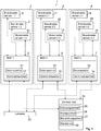
- FIG. 1 System 1 shown schematically for monitoring fire alarm systems has a plurality of fire alarm systems 2, 3, 4. In Fig. 1 only three fire alarm systems 2, 3, 4 are shown here. The system 1 can, however, also comprise fewer (at least two) or more fire alarm systems.
- the fire alarm systems 2, 3, 4 are decentralized (ie at different locations).
- Each of the fire alarm systems 2, 3, 4 has at least one fire alarm center (BMZ).
- the fire alarm center of the fire alarm system 2 is here in Fig. 1 with "BMZ 1" (reference number 5).
- the fire alarm center of the fire alarm system 3 is correspondingly designated with “BMZ 2” (reference number 6) and the fire alarm center of the fire alarm system 4 with “BMZ 3” (reference number 7).
- Each of the fire alarm systems 2, 3, 4 has, in addition to the respective fire alarm center 5, 6, 7, a plurality of fire alarm sensors 8 to 16.
- the fire alarm sensors 8, 9, 10 are assigned to the fire alarm system 2 and are connected to the "BMZ 1" via data connections.
- the fire alarm sensors 11, 12, 13 are part of the fire alarm system 3 and are connected to the "BMZ 2" via data connections.
- the fire alarm sensors 14, 15, 16 are part of the fire alarm system 4 and are connected to the "BMZ 3" via data connections.
- three fire alarm sensors were shown. In reality, however, each of the fire alarm systems has a large number of fire alarm sensors.
- Each fire alarm center 5, 6, 7 has an alarm alarm unit 17, 18, 19.
- the alarm reporting unit 17, 18, 19 detects an alarm from one of the respective associated fire alarm sensors 8 to 16 and forwards it via communication lines, in particular directly to a control center 20 (in particular a fire brigade control center).
- each fire alarm center has a data memory 21, 22, 23.
- Component data of the respective fire alarm system 2, 3, 4 are stored in the data memory 21, 22, 23.
- These are electronic data that represent information about the respective fire alarm center and / or the respective fire alarm sensors. In particular, it concerns status information (current status, status of individual components, error messages) and maintenance information (maintenance intervals, time of next maintenance, time of last maintenance) of the respective fire alarm control panel or the respective fire alarm sensors of the fire alarm system 2, 3, 4.
- the system 1 also has a central unit 24.
- This central unit 24 is connected to the fire alarm systems 2, 3, 4 - more precisely to the respective fire alarm center 5, 6, 7 - via separate data connections (independent of the communication lines of the control center 20 and in particular without a connection to the alarm reporting units 17, 18 and 19).
- the central unit 24 has a detection unit 25, a display unit 26, a checking unit 27 and a warning unit 28.
- the acquisition unit 25 is designed to acquire the component data stored in the data memories 21, 22, 23 (e.g. by reading out the data memories 21, 22, 23) and to hold them centrally in the central unit 24 (e.g. by storing in a, in Fig. 1 data memory (not shown) of the central unit 24).
- the display unit 26 is designed to display the component data acquired and held by the acquisition unit 25 (for example on a screen).
- the checking unit 27 is designed to check whether individual component data with reference data that are stored in the central unit 24, for example in the in Fig. 1 not shown data memory are stored, match or differ from these reference data.
- the warning unit 28 is designed to output a warning (in particular an optical and / or acoustic warning signal) if the checking unit has determined a discrepancy between certain component data and the reference data.
- the component data of the individual fire alarm systems 2, 3, 4 are thus centrally (in one place) by the Display unit 26 of the central unit 24 is displayed. It is not necessary to view the component data in a decentralized manner for each of the plurality of fire alarm systems 2, 3, 4. This reduces the monitoring effort.
- the checking unit 27 can be used to determine centrally whether individual component data differ from setpoint values or whether they correspond to predetermined reference data. By means of the warning unit 28, the persons responsible are made aware that certain component data deviate from reference data.
- the data memory 21, 22, 23 of the fire alarm system 2, 3, 4 is arranged in the respective fire alarm center 5, 6, 7.
- This data memory 21, 22, 23 can also contain information about the fire alarm sensors 8 to 16 connected to the fire alarm center 5, 6, 7.
Landscapes
- Engineering & Computer Science (AREA)
- Computer Security & Cryptography (AREA)
- Physics & Mathematics (AREA)
- General Physics & Mathematics (AREA)
- Fire Alarms (AREA)
Description
- Die Erfindung betrifft ein System und ein Verfahren zur Überwachung von Brandmeldeanlagen. Eine zentrale Überwachung von Brandmeldeanlagen ist in der
WO 2015/107449 beschrieben. - Der Erfindung liegt die Aufgabe zugrunde, ein System zur Überwachung von Brandmeldeanlagen anzubieten, welches eine einfache und unkomplizierte Überwachung einer Mehrzahl von Brandmeldeanlagen ermöglicht. Ferner ist es Aufgabe der Erfindung, ein einfaches und unkompliziertes Verfahren zur Überwachung von Brandmeldeanlagen anzubieten.
- Diese Aufgabe wird durch ein System zur Überwachung von Brandmeldeanlagen mit den Merkmalen des Patentanspruchs 1 bzw. durch ein Verfahren zur Überwachung einer Mehrzahl von Brandmeldeanlagen mit den Merkmalen des Anspruchs 7 gelöst. Vorteilhafte Ausführungsformen sind in den Unteransprüchen beschrieben.
- Erfindungsgemäß weist das System zur Überwachung von Brandmeldeanlagen eine Mehrzahl von Brandmeldeanlagen und eine Zentraleinheit auf. Jede der Brandmeldeanlagen weist eine Brandmeldezentrale, eine Mehrzahl von mit der Brandmeldezentrale verbundene Brandmeldesensoren, eine Alarmmeldeeinheit zur Meldung eines Alarms an eine Leitstelle, und mindestens einen Datenspeicher mit Komponentendaten auf. Die Zentraleinheit weist eine Erfassungseinheit zur Erfassung der Komponentendaten der Brandmeldeanlagen und eine Anzeigeeinheit zur Anzeige der Komponentendaten auf.
- Auf diese Weise werden die Komponentendaten der einzelnen Brandmeldeanlagen zentral (an einem Ort) durch die Zentraleinheit angezeigt. Es ist nicht nötig, die Komponentendaten dezentral bei jeder der Mehrzahl von Brandmeldeanlagen abzurufen. Damit verringert sich der Überwachungsaufwand. Beispielsweise kann ein Betreiber von mehreren Brandmeldeanlagen (z.B. Betreiber eines Infrastrukturprojektes, Gebietskörperschaft,...) zentral einen Überblick über sämtliche angeschlossene Brandmeldeanlagen erlangen, auch wenn die einzelnen Brandmeldeanlagen räumlich voneinander entfernt sind. Die Überwachung vereinfacht sich dadurch.
- Hierbei sind die Komponentendaten insbesondere als Informationen (Daten) über die jeweilige Brandmeldezentrale und/oder die jeweiligen Brandmeldesensoren ausgebildet. Insbesondere kann es sich um Statusinformationen (momentaner Zustand, Zustand einzelner Komponenten, Fehlermeldungen) und/oder Wartungsinformationen (Wartungsintervalle, Zeitpunkt der nächsten Wartung, Zeitpunkt der letzten Wartung) handeln. Auf diese Weise erhält der Betreiber einen zentralen Überblick über den jeweiligen Zustand der dezentral angeordneten Komponenten einer Mehrzahl verschiedener Brandmeldeanlagen.
- In einer vorteilhaften Ausführungsform weist die Zentraleinheit ferner eine Überprüfungseinheit zur Überprüfung der Übereinstimmung der Komponentendaten mit Referenzdaten auf. Auf diese Weise kann zentral bestimmt werden, ob einzelne der Komponentendaten sich von Sollwerten unterscheiden bzw. mit vorgegebenen Referenzdaten übereinstimmen. In einer besonders vorteilhaften Ausführungsform weist die Zentraleinheit ferner eine Warneinheit zur Ausgabe einer Warnung in Abhängigkeit von der durch die Überprüfungseinheit durchgeführten Überprüfung auf. Diese Warnung kann insbesondere ein optisches und/oder akustisches Warnsignal oder die Ausgabe eines elektronischen Warnsignals sein. Auf diese Weise werden die zuständigen Personen darauf aufmerksam gemacht, dass bestimmte Komponentendaten von Referenzdaten abweichen. Basierend auf dieser Warnung können dann weitere Aktionen ausgeführt werden (z.B. Auslösen einer Wartung bei Überschreiten des Wartungsintervalls, Vorortprüfung bei Meldung eines Fehlers).
- In einer vorteilhaften Ausführungsform ist in den Brandmeldeanlagen jeweils eine Mehrzahl von Datenspeichern, insbesondere in der jeweiligen Brandmeldezentrale und in mindestens einem der jeweiligen Brandmeldesensoren, ausgebildet. Auf diese Weise können Komponentendaten von einer Vielzahl von Komponenten einer Brandmeldeanlage (nämlich Brandmeldezentral und Brandmeldesensoren) zentral überwacht werden.
- In besonders vorteilhafter Weise ist die jeweilige Brandmeldezentrale der Brandmeldeanlagen über eine Datenverbindung mit der Zentraleinheit verbunden. Dies führt zu einer zuverlässigen Datenübertragung der Komponentendaten.
- In vorteilhafter Weise sind Teile der Zentraleinheit in einem lokalen Server oder in Form einer dynamisch an den Bedarf angepassten und über ein Netzwerk zur Verfügung gestellten IT-Infrastruktur ("Cloud") ausgebildet.
- In einer vorteilhaften Ausführungsform sind die Komponentendaten zumindest teilweise mit selektiven Zugriffsrechten geschützt. Auf diese Weise kann ein Datenmissbrauch bzw. eine Datenmanipulation durch unberechtigte Personen verhindert werden.
- Das erfindungsgemäße Verfahren zur Überwachung einer Mehrzahl von Brandmeldeanlagen, wobei jede Brandmeldeanlage eine Brandmeldezentrale, eine Mehrzahl von mit der Brandmeldezentrale verbundene Brandmeldesensoren, eine Alarmmeldeeinheit zur Meldung eines Alarms an eine Leitstelle und mindestens einen Datenspeicher mit Komponentendaten aufweist, besitzt die folgenden Verfahrensschritte: (1) Erfassen der Komponentendaten der Brandmeldeanlagen in einer Zentraleinheit; und (2) Anzeigen der Komponentendaten durch eine Anzeigeeinheit der Zentraleinheit.
- Auf diese Weise werden die Komponentendaten der einzelnen Brandmeldeanlagen zentral angezeigt. Dies erleichtert die Überwachung mehrerer Brandmeldeanlagen.
- Die Erfindung ist durch die angehängten Ansprüche definiert und wird anhand eines Ausführungsbeispiels in der Zeichnungsfigur weiter erläutert.
- Fig. 1
- zeigt ein Blockschema eines Systems zur Überwachung von Brandmeldeanlagen.
- Das in
Fig. 1 schematisch dargestellte System 1 zur Überwachung von Brandmeldeanlagen weist eine Mehrzahl von Brandmeldeanlagen 2, 3, 4 auf. InFig. 1 sind hierbei lediglich drei Brandmeldeanlagen 2, 3, 4 dargestellt. Das System 1 kann jedoch auch weniger (mindestens zwei) oder mehr Brandmeldeanlagen umfassen. Die Brandmeldeanlagen 2, 3, 4 sind dezentral (d.h. an verschiedenen Örtlichkeiten) angeordnet. Jede der Brandmeldeanlagen 2, 3, 4 weist mindestens eine Brandmeldezentrale (BMZ) auf. Die Brandmeldezentrale der Brandmeldeanlage 2 wird hierbei inFig. 1 mit "BMZ 1" (Bezugszeichen 5) bezeichnet. Die Brandmeldezentrale der Brandmeldeanlage 3 wird entsprechend mit "BMZ 2" (Bezugszeichen 6) und die Brandmeldezentrale der Brandmeldeanlage 4 mit "BMZ 3" (Bezugszeichen 7) bezeichnet. - Jede der Brandmeldeanlagen 2, 3, 4 weist neben der jeweiligen Brandmeldezentrale 5, 6, 7 eine Mehrzahl von Brandmeldesensoren 8 bis 16 auf. Die Brandmeldesensoren 8, 9, 10 sind hierbei der Brandmeldeanlage 2 zugeordnet und sind über Datenverbindungen mit der "BMZ 1" verbunden. In ähnlicher Weise sind die Brandmeldesensoren 11, 12, 13 Bestandteil der Brandmeldeanlage 3 und über Datenverbindungen mit der "BMZ 2" verbunden. Die Brandmeldesensoren 14, 15, 16 sind Bestandteil der Brandmeldeanlage 4 und sind über Datenverbindungen mit der "BMZ 3" verbunden. Für jede der Brandmeldeanlagen wurden drei Brandmeldesensoren dargestellt. In Realität weist jede der Brandmeldeanlagen jedoch eine Vielzahl von Brandmeldesensoren auf.
- Jede Brandmeldezentrale 5, 6, 7 weist eine Alarmmeldeeinheit 17, 18, 19 auf. Die Alarmmeldeeinheit 17, 18, 19 erfasst einen Alarm eines der jeweils zugehörigen Brandmeldesensoren 8 bis 16 und leitet diesen über Kommunikationsleitungen insbesondere direkt an eine Leitstelle 20 (insbesondere Feuerwehrleitstelle) weiter.
- Des Weiteren besitzt jede Brandmeldezentrale einen Datenspeicher 21, 22, 23. In dem Datenspeicher 21, 22, 23 sind Komponentendaten der jeweiligen Brandmeldeanlage 2, 3, 4 gespeichert. Hierbei handelt es sich um elektronische Daten, die Informationen über die jeweilige Brandmeldezentrale und/oder die jeweiligen Brandmeldesensoren repräsentieren. Insbesondere handelt es sich um Statusinformationen (momentaner Zustand, Zustand einzelner Komponenten, Fehlermeldungen) und Wartungsinformationen (Wartungsintervalle, Zeitpunkt der nächsten Wartung, Zeitpunkt der letzten Wartung) der jeweiligen Brandmeldezentrale bzw. der jeweiligen Brandmeldesensoren der Brandmeldeanlage 2, 3, 4.
- Das System 1 weist ferner eine Zentraleinheit 24 auf. Diese Zentraleinheit 24 ist durch separate Datenverbindungen (unabhängig von den Kommunikationsleitungen der Leitstelle 20 und insbesondere ohne Verbindung zu den Alarmmeldeeinheiten 17, 18 und 19) mit den Brandmeldeanlagen 2, 3, 4 - genauer mit der jeweiligen Brandmeldezentrale 5, 6, 7 - verbunden. Die Zentraleinheit 24 weist eine Erfassungseinheit 25, eine Anzeigeeinheit 26, eine Überprüfungseinheit 27 und eine Warneinheit 28 auf.
- Die Erfassungseinheit 25 ist ausgebildet, die in den Datenspeichern 21, 22, 23 gespeicherten Komponentendaten zu erfassen (z.B. durch Auslesen der Datenspeicher 21, 22, 23) und zentral in der Zentraleinheit 24 vorzuhalten (z.B. durch Speichern in einem, in
Fig. 1 nicht dargestellten Datenspeicher der Zentraleinheit 24). - Die Anzeigeeinheit 26 ist ausgebildet, die von der Erfassungseinheit 25 erfassten und vorgehaltenen Komponentendaten anzuzeigen (z.B. auf einem Bildschirm).
- Die Überprüfungseinheit 27 ist ausgebildet, zu überprüfen, ob einzelne Komponentendaten mit Referenzdaten, die in der Zentraleinheit 24 beispielsweise in dem in
Fig. 1 nicht dargestellten Datenspeicher abgelegt sind, übereinstimmen oder von diesen Referenzdaten abweichen. - Die Warneinheit 28 ist ausgebildet, eine Warnung (insbesondere optisches und/oder akustisches Warnsignal) auszugeben, falls die Überprüfungseinheit eine Abweichung bestimmter Komponentendaten von den Referenzdaten ermittelt hat.
- In dem System 1 werden die Komponentendaten der einzelnen Brandmeldeanlagen 2, 3, 4 damit zentral (an einem Ort) durch die Anzeigeeinheit 26 der Zentraleinheit 24 angezeigt. Es ist nicht nötig, die Komponentendaten dezentral bei jeder der Mehrzahl von Brandmeldeanlagen 2, 3, 4 zu betrachten. Damit verringert sich der Überwachungsaufwand. Durch die Überprüfungseinheit 27 kann zentral bestimmt werden, ob einzelne der Komponentendaten sich von Sollwerten unterscheiden bzw. mit vorgegebenen Referenzdaten übereinstimmen. Durch die Warneinheit 28 werden die zuständigen Personen darauf aufmerksam gemacht, dass bestimmte Komponentendaten von Referenzdaten abweichen.
- In der in
Fig. 1 dargestellten Ausführungsform ist der Datenspeicher 21, 22, 23 der Brandmeldeanlage 2, 3, 4 in der jeweiligen Brandmeldezentrale 5, 6, 7 angeordnet. Dieser Datenspeicher 21, 22, 23 kann auch Informationen über die jeweils mit der Brandmeldezentrale 5, 6, 7 verbundenen Brandmeldesensoren 8 bis 16 beinhalten. Es ist jedoch auch möglich, dass zusätzlich in einigen oder allen der Brandmeldesensoren 8 bis 16 eigene (zusätzliche) Datenspeicher ausgebildet sind, in denen jeweils die Komponentendaten des jeweiligen Brandmeldesensors 8 bis 16 gespeichert sind. -
- 1
- System zur Überwachung von Brandmeldeanlagen
- 2, 3, 4
- Brandmeldeanlage
- 5, 6, 7
- Brandmeldezentrale (BMZ)
- 8 - 16
- Brandmeldesensor
- 17, 18, 19
- Alarmmeldeeinheit
- 20
- Leitstelle
- 21, 22, 23
- Datenspeicher
- 24
- Zentraleinheit
- 25
- Erfassungseinheit
- 26
- Anzeigeeinheit
- 27
- Überprüfungseinheit
- 28
- Warneinheit
Claims (4)
- System (1) zur Überwachung von Brandmeldeanlagen (2, 3, 4), aufweisend:- eine Mehrzahl von Brandmeldeanlagen (2, 3, 4), wobei jede Brandmeldeanlage (2, 3, 4) aufweist:• eine Brandmeldezentrale (5, 6, 7),• eine Mehrzahl von mit der Brandmeldezentrale (5, 6, 7) verbundene Brandmeldesensoren (8-16),• eine Alarmmeldeeinheit (17, 18, 19) zur Meldung eines Alarms an eine Leitstelle (20), und• mindestens einen Datenspeicher (21, 22, 23) mit Komponentendaten; sowie- eine Zentraleinheit (24), wobei die Zentraleinheit (24) aufweist:dadurch gekennzeichnet, dass:• eine Erfassungseinheit (25) zur Erfassung der Komponentendaten der Brandmeldeanlagen (2, 3, 4),• eine Anzeigeeinheit (26) zur Anzeige der Komponentendaten, und• eine Überprüfungseinheit (27) zur Überprüfung der Übereinstimmung der Komponentendaten mit Referenzdaten;- die Zentraleinheit (24) ferner eine Warneinheit (28) zur Ausgabe einer Warnung in Abhängigkeit von der durch die Überprüfungseinheit (27) durchgeführten Überprüfung aufweist, und- die Komponentendaten als Informationen über die jeweilige Brandmeldezentrale (5, 6, 7) und/oder die jeweiligen Brandmeldesensoren (8-16), nämlich als Statusinformationen und/oder Wartungsinformationen, ausgebildet sind.
- System nach Anspruch 1, wobei in den Brandmeldeanlagen (2, 3, 4) jeweils eine Mehrzahl von Datenspeichern (21, 22, 23), insbesondere in der jeweiligen Brandmeldezentrale (5, 6, 7) und in mindestens einem der jeweiligen Brandmeldesensoren (8-16), ausgebildet ist.
- System nach einem der vorhergehenden Ansprüche, wobei die jeweilige Brandmeldezentrale (5, 6, 7) der Brandmeldeanlagen (2, 3, 4) über eine Datenverbindung mit der Zentraleinheit (24) verbunden ist.
- Verfahren zur Überwachung einer Mehrzahl von Brandmeldeanlagen (2, 3, 4), wobei jede Brandmeldeanlage (2, 3, 4) aufweist: eine Brandmeldezentrale (5, 6, 7), eine Mehrzahl von mit der Brandmeldezentrale (5, 6, 7) verbundene Brandmeldesensoren (8-16), eine Alarmmeldeeinheit (17, 18, 19) zur Meldung eines Alarms an eine Leitstelle (20), und mindestens einen Datenspeicher (21, 22, 23) mit Komponentendaten, wobei das Verfahren folgende Verfahrensschritte aufweist:- Erfassen der Komponentendaten der Brandmeldeanlagen (2, 3, 4) in einer Zentraleinheit (24), wobei die Komponentendaten als Informationen über die jeweilige Brandmeldezentrale (5, 6, 7) und/oder die jeweiligen Brandmeldesensoren (8-16), nämlich als Statusinformationen und/oder Wartungsinformationen, ausgebildet sind;- Anzeigen der Komponentendaten durch eine Anzeigeeinheit (26) der Zentraleinheit (24);- Überprüfen der Übereinstimmung der Komponentendaten mit Referenzdaten; und- Ausgeben einer Warnung durch eine Warneinheit (28) der Zentraleinheit (24) in Abhängigkeit vom Ergebnis der durchgeführten Überprüfung.
Priority Applications (1)
| Application Number | Priority Date | Filing Date | Title |
|---|---|---|---|
| EP15201952.7A EP3185228B1 (de) | 2015-12-22 | 2015-12-22 | System und verfahren zur überwachung von brandmeldeanlagen |
Applications Claiming Priority (1)
| Application Number | Priority Date | Filing Date | Title |
|---|---|---|---|
| EP15201952.7A EP3185228B1 (de) | 2015-12-22 | 2015-12-22 | System und verfahren zur überwachung von brandmeldeanlagen |
Publications (2)
| Publication Number | Publication Date |
|---|---|
| EP3185228A1 EP3185228A1 (de) | 2017-06-28 |
| EP3185228B1 true EP3185228B1 (de) | 2020-12-02 |
Family
ID=54979553
Family Applications (1)
| Application Number | Title | Priority Date | Filing Date |
|---|---|---|---|
| EP15201952.7A Revoked EP3185228B1 (de) | 2015-12-22 | 2015-12-22 | System und verfahren zur überwachung von brandmeldeanlagen |
Country Status (1)
| Country | Link |
|---|---|
| EP (1) | EP3185228B1 (de) |
Cited By (1)
| Publication number | Priority date | Publication date | Assignee | Title |
|---|---|---|---|---|
| EP4462400A1 (de) * | 2023-05-12 | 2024-11-13 | Robert Bosch GmbH | Recheneinheit zur ermittlung und anzeige eines zustands einer gefahrenmeldeanlage und gefahrenmeldesystem mit einer solchen recheneinheit |
Families Citing this family (2)
| Publication number | Priority date | Publication date | Assignee | Title |
|---|---|---|---|---|
| AT524137B1 (de) | 2020-08-26 | 2025-08-15 | Pke Holding Ag | Tragbare Vorrichtung zur Steuerung eines Brandfalles |
| DE102023212015A1 (de) * | 2023-11-30 | 2025-06-05 | Robert Bosch Gesellschaft mit beschränkter Haftung | Verfahren zur Inspektion des Installationszustands von mindestens einen Systemkomponente in einer Brandmeldeanordnung, Brandmeldeanordnung, Monitorzentrale, Computerprogramm und Speichermedium |
Citations (16)
| Publication number | Priority date | Publication date | Assignee | Title |
|---|---|---|---|---|
| US5686896A (en) | 1995-09-28 | 1997-11-11 | Interactive Technologies, Inc. | Low battery report inhibitor for a sensor |
| US6078050A (en) | 1996-03-01 | 2000-06-20 | Fire Sentry Corporation | Fire detector with event recordation |
| US6989756B2 (en) | 2002-06-20 | 2006-01-24 | Siemens Building Technologies, Inc. | Smoke detector maintenance indication method and apparatus |
| US20070139183A1 (en) | 2005-12-19 | 2007-06-21 | Lawrence Kates | Portable monitoring unit |
| EP1845499A2 (de) | 2006-04-13 | 2007-10-17 | Siemens Building Technologies, Inc./Cerberus Div. | Drahtloses Dienstwerkzeug für automatisierte Schutzsysteme |
| AT501215B1 (de) | 2004-12-20 | 2008-05-15 | Friedl Helmut Dipl Ing | Überwachungseinrichtung |
| US20080262816A1 (en) | 2007-04-23 | 2008-10-23 | Karen Lontka | Method and system for testing a building control system |
| US20080309486A1 (en) | 2005-09-20 | 2008-12-18 | Selflink Llc | Self-configuring emergency event alarm system having connection to a public safety answering point |
| WO2011109622A2 (en) | 2010-03-03 | 2011-09-09 | Honeywell International Inc. | Aspirating environmental sensor with webserver and email notification |
| WO2011128100A1 (de) | 2010-04-16 | 2011-10-20 | Winrich Hoseit | Brandmelder zur überwachung eines raumes mittels kombination aus rauchdichte- und temperatur-messung |
| US20130321161A1 (en) | 2012-05-31 | 2013-12-05 | Hon Hai Precision Industry Co., Ltd. | Cloud-based fire alarm control system |
| WO2014044818A1 (de) | 2012-09-24 | 2014-03-27 | Robert Bosch Gmbh | Brandmeldeanlage und brandmeldenetzwerk mit einer mehrzahl von brandmeldeanlagen |
| WO2014044675A1 (de) | 2012-09-24 | 2014-03-27 | Robert Bosch Gmbh | Auswerteeinrichtung für ein überwachungssystem sowie überwachungssystem mit der auswerteeinrichtung |
| US8836467B1 (en) | 2010-09-28 | 2014-09-16 | Icontrol Networks, Inc. | Method, system and apparatus for automated reporting of account and sensor zone information to a central station |
| WO2015048894A1 (en) | 2013-10-03 | 2015-04-09 | Tyco Safety Products Canada Ltd. | Method and apparatus for determining maintenance needs and validating the installation of an alarm system |
| WO2015107449A1 (en) | 2014-01-17 | 2015-07-23 | Tyco Fire & Security Gmbh | Testing system and method for fire alarm system |
-
2015
- 2015-12-22 EP EP15201952.7A patent/EP3185228B1/de not_active Revoked
Patent Citations (17)
| Publication number | Priority date | Publication date | Assignee | Title |
|---|---|---|---|---|
| US5686896A (en) | 1995-09-28 | 1997-11-11 | Interactive Technologies, Inc. | Low battery report inhibitor for a sensor |
| US6078050A (en) | 1996-03-01 | 2000-06-20 | Fire Sentry Corporation | Fire detector with event recordation |
| US6989756B2 (en) | 2002-06-20 | 2006-01-24 | Siemens Building Technologies, Inc. | Smoke detector maintenance indication method and apparatus |
| AT501215B1 (de) | 2004-12-20 | 2008-05-15 | Friedl Helmut Dipl Ing | Überwachungseinrichtung |
| US20080309486A1 (en) | 2005-09-20 | 2008-12-18 | Selflink Llc | Self-configuring emergency event alarm system having connection to a public safety answering point |
| US20070139183A1 (en) | 2005-12-19 | 2007-06-21 | Lawrence Kates | Portable monitoring unit |
| EP1845499A2 (de) | 2006-04-13 | 2007-10-17 | Siemens Building Technologies, Inc./Cerberus Div. | Drahtloses Dienstwerkzeug für automatisierte Schutzsysteme |
| US20080262816A1 (en) | 2007-04-23 | 2008-10-23 | Karen Lontka | Method and system for testing a building control system |
| WO2011109622A2 (en) | 2010-03-03 | 2011-09-09 | Honeywell International Inc. | Aspirating environmental sensor with webserver and email notification |
| WO2011128100A1 (de) | 2010-04-16 | 2011-10-20 | Winrich Hoseit | Brandmelder zur überwachung eines raumes mittels kombination aus rauchdichte- und temperatur-messung |
| US8836467B1 (en) | 2010-09-28 | 2014-09-16 | Icontrol Networks, Inc. | Method, system and apparatus for automated reporting of account and sensor zone information to a central station |
| US20130321161A1 (en) | 2012-05-31 | 2013-12-05 | Hon Hai Precision Industry Co., Ltd. | Cloud-based fire alarm control system |
| WO2014044818A1 (de) | 2012-09-24 | 2014-03-27 | Robert Bosch Gmbh | Brandmeldeanlage und brandmeldenetzwerk mit einer mehrzahl von brandmeldeanlagen |
| WO2014044675A1 (de) | 2012-09-24 | 2014-03-27 | Robert Bosch Gmbh | Auswerteeinrichtung für ein überwachungssystem sowie überwachungssystem mit der auswerteeinrichtung |
| WO2015048894A1 (en) | 2013-10-03 | 2015-04-09 | Tyco Safety Products Canada Ltd. | Method and apparatus for determining maintenance needs and validating the installation of an alarm system |
| US20150097664A1 (en) | 2013-10-03 | 2015-04-09 | Tyco Safety Products Canada Ltd. | Method and apparatus for determining maintenance needs and validating the installation of an alarm system |
| WO2015107449A1 (en) | 2014-01-17 | 2015-07-23 | Tyco Fire & Security Gmbh | Testing system and method for fire alarm system |
Non-Patent Citations (22)
| Title |
|---|
| ALVIS 3.2 New Features |
| ANONYMOUS: "Brandmeldeanlagen - Teil 2: Brandmelderzentralen; Deutsche Fassung DIN EN 54-2:1997", DEUTSCH NORM, 1 January 1997 (1997-01-01), pages 1 - 27, XP055844012 |
| ANONYMOUS: "Brandmeldeanlagen - Teil 2: Brandmelderzentralen; Deutsche Fassung DIN EN 54-2:1997/A1", DEUTSCHE NORM, 1 January 2006 (2006-01-01), pages 1 - 42, XP055844015 |
| ANONYMOUS: "FC2020-CZ, FC2020-CC", SIEMENS, 1 January 2014 (2014-01-01), pages 1 - 10, XP055844003, Retrieved from the Internet <URL:https://ch.bt-pip.com/uploads/master/product/documents/fc2020cc_fc2020cc_023_02_de.pdf> [retrieved on 20210923] |
| ANONYMOUS: "Messe-Highlight Aplis Aplis", RE GRAPH GRAPHISCHE INFOSYSTEME, GEORG THIEME VERLAG KG, STUTTGART · NEW YORK, 1 September 2014 (2014-09-01), Stuttgart · New York, pages 1 - 2, XP055844020, Retrieved from the Internet <URL:https://www.regraph.de/news_files/Highlights.pdf> [retrieved on 20210923], DOI: 10.1055/s-0034-1393880 |
| ANONYMOUS: "Sinteso FS20-Zentralen – klares Konzept, effiziente Bedienung", SIEMENS, 1 January 2015 (2015-01-01), pages 1 - 16, XP055844000 |
| Brandmelderzentrale Serie BC216 Handbuch Teil A |
| Brandmelderzentrale Serie BC216 Handbuch Teil C |
| Einsatzleitsystem ALVIS 3.0 |
| Handbuch ADM Melder fur Vorgangersystem LBC1000 |
| Integral remote : Femzugriff auf Brandmeldezentralen |
| Katalog Brandmeldetechnik 2007/2008 |
| KÖNINGS OLIVER: "BMACLOUD für Errichter erstellen sie ihre Prüfplan online und bei der Wartung füllen Sie diese per App aus", BMACLOUD, 1 January 2014 (2014-01-01), pages 1 - 11, XP055844008 |
| MULLER R., HUPPI S.: "Fire Tablet plus, Mobiles Service interface zu Siemens Brandmeldeanlagen Bachelorarbeit", HSR, HOCHSCHULE FUR TECHNIK, 2011, pages 1 - 102, XP055841334 |
| Produktbeschreibung Esser remote access (September 2014) |
| Produktbeschreibung Siemens Sinteso FS20 (Mai 2015) |
| Produktinformation SMS2-1 |
| Protokoll + Teilnehmerliste zur Sitzung des FA Brandmeldetechnik am 14.10 |
| SMS/ E-Mail -Sendermodul SMS2-1 Beschreibung |
| Stellungnahme der Patentinhaberin im Prufungsverfahren |
| Tagesordnung zur Sitzung des FA Brandmeldetechnik am 14. 10.2015 |
| Vortrag REACT |
Cited By (1)
| Publication number | Priority date | Publication date | Assignee | Title |
|---|---|---|---|---|
| EP4462400A1 (de) * | 2023-05-12 | 2024-11-13 | Robert Bosch GmbH | Recheneinheit zur ermittlung und anzeige eines zustands einer gefahrenmeldeanlage und gefahrenmeldesystem mit einer solchen recheneinheit |
Also Published As
| Publication number | Publication date |
|---|---|
| EP3185228A1 (de) | 2017-06-28 |
Similar Documents
| Publication | Publication Date | Title |
|---|---|---|
| DE3338711C2 (de) | Feuerüberwachungs- und Alarmanlage | |
| EP3623891A1 (de) | Individualisierbare bildhierarchien für ein leitsystem einer technischen anlage | |
| EP3185228B1 (de) | System und verfahren zur überwachung von brandmeldeanlagen | |
| EP3528074A1 (de) | Verfahren zum überprüfen der beziehung zwischen einem visuell auf einem operator-client eines prozessleitsystems dargestellten und einem akustisch ausgegebenen prozessalarm eines prozessobjektes sowie operator-system | |
| DE3128811C2 (de) | ||
| DE102021123618A1 (de) | Informationsübermittlungsvorrichtung, Server und Informationsübermittlungsverfahren | |
| EP3637205A1 (de) | Bildaufschaltung auf einem operator station client | |
| EP1713035A2 (de) | Datenübertragungsvorrichtung | |
| DE112016001586T5 (de) | Relaisvorrichtung und Programm | |
| EP3108308A2 (de) | Verfahren zur bestimmung eines master-zeitsignals, fahrzeug und system | |
| DE4228917A1 (de) | Verfahren zum signaltechnisch sicheren Anzeigen verkehrstechnischer Informationen eines Verkehrswegesystems | |
| DE102019005978A1 (de) | Gasmesssystem und Verfahren zum Betreiben eines Gasmesssystems . | |
| DE102023103481A1 (de) | Fahrzeugeigene Vorrichtung und Log-Verwaltungsverfahren | |
| DE102007026528B4 (de) | Verfahren zum Sammeln von Überwachungsdaten | |
| DE102021204206A1 (de) | Verfahren zur Steuerung einer Datenübertragung | |
| DE102016009199B4 (de) | Verfahren zum Betreiben einer Datenerfassungseinheit zum Erfassen von mindestens einem Steuerungsereignis einer Steuerungvorrichtung eines Kraftfahrzeugs sowie eine Datenerfassungseinheit und eine Datenverarbeitungseinheit | |
| EP3504699B1 (de) | Vorrichtung und verfahren zur verifizierbaren ausgabe von bildern durch einen bildschirm | |
| DE10115897C2 (de) | Verfahren und Vorrichtung zur Bereitstellung von Informationen für die Analyse von Fehlern bei einer technischen Anlage | |
| WO2020038700A1 (de) | Vorrichtung zur absicherung von signalen | |
| DE102024103717A1 (de) | Computerimplementiertes Verfahren, System und Computerprogrammprodukt zur automatischen Konfiguration einer Service-Anwendung für Gasmessgeräte | |
| EP3347858B1 (de) | Vorrichtung und verfahren zum verarbeiten einer wenigstens eine information darstellenden bilddarstellung | |
| EP1944666A1 (de) | Elektronische Schaltvorrichtung und Verfahren zur Schaltung autonomer Interventionsmittel zur automatisierten Behebung von Betriebsstörungen | |
| DE112023004773T5 (de) | Angriffsanalysevorrichtung | |
| EP4530765A1 (de) | Leitsystem für eine technische anlage und betriebsverfahren | |
| DE102021004838A1 (de) | Testvorrichtung für eine Militärausrüstung und System mit einer solchen Testvorrichtung |
Legal Events
| Date | Code | Title | Description |
|---|---|---|---|
| PUAI | Public reference made under article 153(3) epc to a published international application that has entered the european phase |
Free format text: ORIGINAL CODE: 0009012 |
|
| STAA | Information on the status of an ep patent application or granted ep patent |
Free format text: STATUS: THE APPLICATION HAS BEEN PUBLISHED |
|
| AK | Designated contracting states |
Kind code of ref document: A1 Designated state(s): AL AT BE BG CH CY CZ DE DK EE ES FI FR GB GR HR HU IE IS IT LI LT LU LV MC MK MT NL NO PL PT RO RS SE SI SK SM TR |
|
| AX | Request for extension of the european patent |
Extension state: BA ME |
|
| STAA | Information on the status of an ep patent application or granted ep patent |
Free format text: STATUS: REQUEST FOR EXAMINATION WAS MADE |
|
| 17P | Request for examination filed |
Effective date: 20171201 |
|
| RBV | Designated contracting states (corrected) |
Designated state(s): AL AT BE BG CH CY CZ DE DK EE ES FI FR GB GR HR HU IE IS IT LI LT LU LV MC MK MT NL NO PL PT RO RS SE SI SK SM TR |
|
| GRAP | Despatch of communication of intention to grant a patent |
Free format text: ORIGINAL CODE: EPIDOSNIGR1 |
|
| STAA | Information on the status of an ep patent application or granted ep patent |
Free format text: STATUS: GRANT OF PATENT IS INTENDED |
|
| INTG | Intention to grant announced |
Effective date: 20200728 |
|
| RIN1 | Information on inventor provided before grant (corrected) |
Inventor name: SCHRANER, STEFAN |
|
| GRAS | Grant fee paid |
Free format text: ORIGINAL CODE: EPIDOSNIGR3 |
|
| GRAA | (expected) grant |
Free format text: ORIGINAL CODE: 0009210 |
|
| STAA | Information on the status of an ep patent application or granted ep patent |
Free format text: STATUS: THE PATENT HAS BEEN GRANTED |
|
| AK | Designated contracting states |
Kind code of ref document: B1 Designated state(s): AL AT BE BG CH CY CZ DE DK EE ES FI FR GB GR HR HU IE IS IT LI LT LU LV MC MK MT NL NO PL PT RO RS SE SI SK SM TR |
|
| REG | Reference to a national code |
Ref country code: GB Ref legal event code: FG4D Free format text: NOT ENGLISH |
|
| REG | Reference to a national code |
Ref country code: AT Ref legal event code: REF Ref document number: 1341780 Country of ref document: AT Kind code of ref document: T Effective date: 20201215 Ref country code: CH Ref legal event code: EP |
|
| REG | Reference to a national code |
Ref country code: DE Ref legal event code: R096 Ref document number: 502015013933 Country of ref document: DE |
|
| REG | Reference to a national code |
Ref country code: IE Ref legal event code: FG4D Free format text: LANGUAGE OF EP DOCUMENT: GERMAN |
|
| REG | Reference to a national code |
Ref country code: NL Ref legal event code: FP |
|
| PG25 | Lapsed in a contracting state [announced via postgrant information from national office to epo] |
Ref country code: NO Free format text: LAPSE BECAUSE OF FAILURE TO SUBMIT A TRANSLATION OF THE DESCRIPTION OR TO PAY THE FEE WITHIN THE PRESCRIBED TIME-LIMIT Effective date: 20210302 Ref country code: FI Free format text: LAPSE BECAUSE OF FAILURE TO SUBMIT A TRANSLATION OF THE DESCRIPTION OR TO PAY THE FEE WITHIN THE PRESCRIBED TIME-LIMIT Effective date: 20201202 Ref country code: RS Free format text: LAPSE BECAUSE OF FAILURE TO SUBMIT A TRANSLATION OF THE DESCRIPTION OR TO PAY THE FEE WITHIN THE PRESCRIBED TIME-LIMIT Effective date: 20201202 Ref country code: GR Free format text: LAPSE BECAUSE OF FAILURE TO SUBMIT A TRANSLATION OF THE DESCRIPTION OR TO PAY THE FEE WITHIN THE PRESCRIBED TIME-LIMIT Effective date: 20210303 |
|
| PGFP | Annual fee paid to national office [announced via postgrant information from national office to epo] |
Ref country code: FR Payment date: 20210215 Year of fee payment: 6 Ref country code: NL Payment date: 20210218 Year of fee payment: 6 |
|
| PG25 | Lapsed in a contracting state [announced via postgrant information from national office to epo] |
Ref country code: LV Free format text: LAPSE BECAUSE OF FAILURE TO SUBMIT A TRANSLATION OF THE DESCRIPTION OR TO PAY THE FEE WITHIN THE PRESCRIBED TIME-LIMIT Effective date: 20201202 Ref country code: SE Free format text: LAPSE BECAUSE OF FAILURE TO SUBMIT A TRANSLATION OF THE DESCRIPTION OR TO PAY THE FEE WITHIN THE PRESCRIBED TIME-LIMIT Effective date: 20201202 Ref country code: PL Free format text: LAPSE BECAUSE OF FAILURE TO SUBMIT A TRANSLATION OF THE DESCRIPTION OR TO PAY THE FEE WITHIN THE PRESCRIBED TIME-LIMIT Effective date: 20201202 Ref country code: BG Free format text: LAPSE BECAUSE OF FAILURE TO SUBMIT A TRANSLATION OF THE DESCRIPTION OR TO PAY THE FEE WITHIN THE PRESCRIBED TIME-LIMIT Effective date: 20210302 |
|
| PGFP | Annual fee paid to national office [announced via postgrant information from national office to epo] |
Ref country code: DE Payment date: 20210223 Year of fee payment: 6 Ref country code: GB Payment date: 20210222 Year of fee payment: 6 Ref country code: AT Payment date: 20210216 Year of fee payment: 6 |
|
| PG25 | Lapsed in a contracting state [announced via postgrant information from national office to epo] |
Ref country code: HR Free format text: LAPSE BECAUSE OF FAILURE TO SUBMIT A TRANSLATION OF THE DESCRIPTION OR TO PAY THE FEE WITHIN THE PRESCRIBED TIME-LIMIT Effective date: 20201202 |
|
| REG | Reference to a national code |
Ref country code: LT Ref legal event code: MG9D |
|
| PG25 | Lapsed in a contracting state [announced via postgrant information from national office to epo] |
Ref country code: LT Free format text: LAPSE BECAUSE OF FAILURE TO SUBMIT A TRANSLATION OF THE DESCRIPTION OR TO PAY THE FEE WITHIN THE PRESCRIBED TIME-LIMIT Effective date: 20201202 Ref country code: SK Free format text: LAPSE BECAUSE OF FAILURE TO SUBMIT A TRANSLATION OF THE DESCRIPTION OR TO PAY THE FEE WITHIN THE PRESCRIBED TIME-LIMIT Effective date: 20201202 Ref country code: RO Free format text: LAPSE BECAUSE OF FAILURE TO SUBMIT A TRANSLATION OF THE DESCRIPTION OR TO PAY THE FEE WITHIN THE PRESCRIBED TIME-LIMIT Effective date: 20201202 Ref country code: PT Free format text: LAPSE BECAUSE OF FAILURE TO SUBMIT A TRANSLATION OF THE DESCRIPTION OR TO PAY THE FEE WITHIN THE PRESCRIBED TIME-LIMIT Effective date: 20210405 Ref country code: SM Free format text: LAPSE BECAUSE OF FAILURE TO SUBMIT A TRANSLATION OF THE DESCRIPTION OR TO PAY THE FEE WITHIN THE PRESCRIBED TIME-LIMIT Effective date: 20201202 Ref country code: EE Free format text: LAPSE BECAUSE OF FAILURE TO SUBMIT A TRANSLATION OF THE DESCRIPTION OR TO PAY THE FEE WITHIN THE PRESCRIBED TIME-LIMIT Effective date: 20201202 Ref country code: CZ Free format text: LAPSE BECAUSE OF FAILURE TO SUBMIT A TRANSLATION OF THE DESCRIPTION OR TO PAY THE FEE WITHIN THE PRESCRIBED TIME-LIMIT Effective date: 20201202 |
|
| REG | Reference to a national code |
Ref country code: CH Ref legal event code: PL |
|
| REG | Reference to a national code |
Ref country code: DE Ref legal event code: R026 Ref document number: 502015013933 Country of ref document: DE |
|
| PLBI | Opposition filed |
Free format text: ORIGINAL CODE: 0009260 |
|
| REG | Reference to a national code |
Ref country code: BE Ref legal event code: MM Effective date: 20201231 |
|
| PLBI | Opposition filed |
Free format text: ORIGINAL CODE: 0009260 |
|
| PLAX | Notice of opposition and request to file observation + time limit sent |
Free format text: ORIGINAL CODE: EPIDOSNOBS2 |
|
| PG25 | Lapsed in a contracting state [announced via postgrant information from national office to epo] |
Ref country code: IS Free format text: LAPSE BECAUSE OF FAILURE TO SUBMIT A TRANSLATION OF THE DESCRIPTION OR TO PAY THE FEE WITHIN THE PRESCRIBED TIME-LIMIT Effective date: 20210402 Ref country code: MC Free format text: LAPSE BECAUSE OF FAILURE TO SUBMIT A TRANSLATION OF THE DESCRIPTION OR TO PAY THE FEE WITHIN THE PRESCRIBED TIME-LIMIT Effective date: 20201202 |
|
| 26 | Opposition filed |
Opponent name: LABOR STRAUSS SICHERUNGSANLAGENBAU GMBH Effective date: 20210831 |
|
| 26 | Opposition filed |
Opponent name: RE'GRAPH GESELLSCHAFT FUER GRAPHISCHE INFOSYSTEME MBH Effective date: 20210902 Opponent name: IFAM GMBH ERFURT Effective date: 20210902 Opponent name: SCHRACK SECONET AG Effective date: 20210902 Opponent name: HEKATRON VERTRIEBS GMBH Effective date: 20210902 |
|
| PG25 | Lapsed in a contracting state [announced via postgrant information from national office to epo] |
Ref country code: LU Free format text: LAPSE BECAUSE OF NON-PAYMENT OF DUE FEES Effective date: 20201222 Ref country code: AL Free format text: LAPSE BECAUSE OF FAILURE TO SUBMIT A TRANSLATION OF THE DESCRIPTION OR TO PAY THE FEE WITHIN THE PRESCRIBED TIME-LIMIT Effective date: 20201202 Ref country code: IT Free format text: LAPSE BECAUSE OF FAILURE TO SUBMIT A TRANSLATION OF THE DESCRIPTION OR TO PAY THE FEE WITHIN THE PRESCRIBED TIME-LIMIT Effective date: 20201202 Ref country code: IE Free format text: LAPSE BECAUSE OF NON-PAYMENT OF DUE FEES Effective date: 20201222 |
|
| PG25 | Lapsed in a contracting state [announced via postgrant information from national office to epo] |
Ref country code: SI Free format text: LAPSE BECAUSE OF FAILURE TO SUBMIT A TRANSLATION OF THE DESCRIPTION OR TO PAY THE FEE WITHIN THE PRESCRIBED TIME-LIMIT Effective date: 20201202 Ref country code: DK Free format text: LAPSE BECAUSE OF FAILURE TO SUBMIT A TRANSLATION OF THE DESCRIPTION OR TO PAY THE FEE WITHIN THE PRESCRIBED TIME-LIMIT Effective date: 20201202 Ref country code: CH Free format text: LAPSE BECAUSE OF NON-PAYMENT OF DUE FEES Effective date: 20201231 Ref country code: LI Free format text: LAPSE BECAUSE OF NON-PAYMENT OF DUE FEES Effective date: 20201231 |
|
| PG25 | Lapsed in a contracting state [announced via postgrant information from national office to epo] |
Ref country code: ES Free format text: LAPSE BECAUSE OF FAILURE TO SUBMIT A TRANSLATION OF THE DESCRIPTION OR TO PAY THE FEE WITHIN THE PRESCRIBED TIME-LIMIT Effective date: 20201202 |
|
| RDAF | Communication despatched that patent is revoked |
Free format text: ORIGINAL CODE: EPIDOSNREV1 |
|
| REG | Reference to a national code |
Ref country code: DE Ref legal event code: R103 Ref document number: 502015013933 Country of ref document: DE Ref country code: DE Ref legal event code: R064 Ref document number: 502015013933 Country of ref document: DE |
|
| PG25 | Lapsed in a contracting state [announced via postgrant information from national office to epo] |
Ref country code: IS Free format text: LAPSE BECAUSE OF FAILURE TO SUBMIT A TRANSLATION OF THE DESCRIPTION OR TO PAY THE FEE WITHIN THE PRESCRIBED TIME-LIMIT Effective date: 20210402 Ref country code: TR Free format text: LAPSE BECAUSE OF FAILURE TO SUBMIT A TRANSLATION OF THE DESCRIPTION OR TO PAY THE FEE WITHIN THE PRESCRIBED TIME-LIMIT Effective date: 20201202 Ref country code: MT Free format text: LAPSE BECAUSE OF FAILURE TO SUBMIT A TRANSLATION OF THE DESCRIPTION OR TO PAY THE FEE WITHIN THE PRESCRIBED TIME-LIMIT Effective date: 20201202 Ref country code: CY Free format text: LAPSE BECAUSE OF FAILURE TO SUBMIT A TRANSLATION OF THE DESCRIPTION OR TO PAY THE FEE WITHIN THE PRESCRIBED TIME-LIMIT Effective date: 20201202 |
|
| PG25 | Lapsed in a contracting state [announced via postgrant information from national office to epo] |
Ref country code: MK Free format text: LAPSE BECAUSE OF FAILURE TO SUBMIT A TRANSLATION OF THE DESCRIPTION OR TO PAY THE FEE WITHIN THE PRESCRIBED TIME-LIMIT Effective date: 20201202 |
|
| RDAG | Patent revoked |
Free format text: ORIGINAL CODE: 0009271 |
|
| STAA | Information on the status of an ep patent application or granted ep patent |
Free format text: STATUS: PATENT REVOKED |
|
| PG25 | Lapsed in a contracting state [announced via postgrant information from national office to epo] |
Ref country code: BE Free format text: LAPSE BECAUSE OF NON-PAYMENT OF DUE FEES Effective date: 20201231 |
|
| REG | Reference to a national code |
Ref country code: CH Ref legal event code: PL |
|
| REG | Reference to a national code |
Ref country code: NL Ref legal event code: MM Effective date: 20220101 |
|
| REG | Reference to a national code |
Ref country code: AT Ref legal event code: MM01 Ref document number: 1341780 Country of ref document: AT Kind code of ref document: T Effective date: 20211222 |
|
| REG | Reference to a national code |
Ref country code: FI Ref legal event code: MGE |
|
| 27W | Patent revoked |
Effective date: 20220410 |
|
| GBPR | Gb: patent revoked under art. 102 of the ep convention designating the uk as contracting state |
Effective date: 20220410 |
|
| PG25 | Lapsed in a contracting state [announced via postgrant information from national office to epo] |
Ref country code: NL Free format text: LAPSE BECAUSE OF NON-PAYMENT OF DUE FEES Effective date: 20220101 |
|
| REG | Reference to a national code |
Ref country code: AT Ref legal event code: MA03 Ref document number: 1341780 Country of ref document: AT Kind code of ref document: T Effective date: 20220410 |
|
| PG25 | Lapsed in a contracting state [announced via postgrant information from national office to epo] |
Ref country code: AT Free format text: LAPSE BECAUSE OF THE APPLICANT RENOUNCES Effective date: 20220410 |
|
| PG25 | Lapsed in a contracting state [announced via postgrant information from national office to epo] |
Ref country code: AT Free format text: LAPSE BECAUSE OF THE APPLICANT RENOUNCES Effective date: 20220410 |
|
| PG25 | Lapsed in a contracting state [announced via postgrant information from national office to epo] |
Ref country code: FR Free format text: LAPSE BECAUSE OF NON-PAYMENT OF DUE FEES Effective date: 20220410 |
|
| PG25 | Lapsed in a contracting state [announced via postgrant information from national office to epo] |
Ref country code: FR Free format text: LAPSE BECAUSE OF NON-PAYMENT OF DUE FEES Effective date: 20211222 |
|
| PG25 | Lapsed in a contracting state [announced via postgrant information from national office to epo] |
Ref country code: GB Free format text: LAPSE BECAUSE OF NON-PAYMENT OF DUE FEES Effective date: 20211222 |