EP3185192A1 - Fast device replacement system - Google Patents
Fast device replacement system Download PDFInfo
- Publication number
- EP3185192A1 EP3185192A1 EP16203378.1A EP16203378A EP3185192A1 EP 3185192 A1 EP3185192 A1 EP 3185192A1 EP 16203378 A EP16203378 A EP 16203378A EP 3185192 A1 EP3185192 A1 EP 3185192A1
- Authority
- EP
- European Patent Office
- Prior art keywords
- control device
- specific
- physical location
- specific physical
- nfc
- Prior art date
- Legal status (The legal status is an assumption and is not a legal conclusion. Google has not performed a legal analysis and makes no representation as to the accuracy of the status listed.)
- Withdrawn
Links
Images



Classifications
-
- H—ELECTRICITY
- H04—ELECTRIC COMMUNICATION TECHNIQUE
- H04L—TRANSMISSION OF DIGITAL INFORMATION, e.g. TELEGRAPHIC COMMUNICATION
- H04L41/00—Arrangements for maintenance, administration or management of data switching networks, e.g. of packet switching networks
- H04L41/08—Configuration management of networks or network elements
- H04L41/0803—Configuration setting
- H04L41/0813—Configuration setting characterised by the conditions triggering a change of settings
-
- G—PHYSICS
- G06—COMPUTING OR CALCULATING; COUNTING
- G06Q—INFORMATION AND COMMUNICATION TECHNOLOGY [ICT] SPECIALLY ADAPTED FOR ADMINISTRATIVE, COMMERCIAL, FINANCIAL, MANAGERIAL OR SUPERVISORY PURPOSES; SYSTEMS OR METHODS SPECIALLY ADAPTED FOR ADMINISTRATIVE, COMMERCIAL, FINANCIAL, MANAGERIAL OR SUPERVISORY PURPOSES, NOT OTHERWISE PROVIDED FOR
- G06Q10/00—Administration; Management
- G06Q10/08—Logistics, e.g. warehousing, loading or distribution; Inventory or stock management
-
- H—ELECTRICITY
- H04—ELECTRIC COMMUNICATION TECHNIQUE
- H04L—TRANSMISSION OF DIGITAL INFORMATION, e.g. TELEGRAPHIC COMMUNICATION
- H04L41/00—Arrangements for maintenance, administration or management of data switching networks, e.g. of packet switching networks
- H04L41/06—Management of faults, events, alarms or notifications
- H04L41/0654—Management of faults, events, alarms or notifications using network fault recovery
- H04L41/0668—Management of faults, events, alarms or notifications using network fault recovery by dynamic selection of recovery network elements, e.g. replacement by the most appropriate element after failure
-
- H—ELECTRICITY
- H04—ELECTRIC COMMUNICATION TECHNIQUE
- H04B—TRANSMISSION
- H04B5/00—Near-field transmission systems, e.g. inductive or capacitive transmission systems
- H04B5/20—Near-field transmission systems, e.g. inductive or capacitive transmission systems characterised by the transmission technique; characterised by the transmission medium
-
- H—ELECTRICITY
- H04—ELECTRIC COMMUNICATION TECHNIQUE
- H04L—TRANSMISSION OF DIGITAL INFORMATION, e.g. TELEGRAPHIC COMMUNICATION
- H04L41/00—Arrangements for maintenance, administration or management of data switching networks, e.g. of packet switching networks
- H04L41/08—Configuration management of networks or network elements
- H04L41/0803—Configuration setting
- H04L41/0823—Configuration setting characterised by the purposes of a change of settings, e.g. optimising configuration for enhancing reliability
- H04L41/0836—Configuration setting characterised by the purposes of a change of settings, e.g. optimising configuration for enhancing reliability to enhance reliability, e.g. reduce downtime
Definitions
- the invention is generally related to the replacement of industrial control devices and particularly to rapid replacement of a control device to minimize system down time and device setup time.
- the memory module When replacement is required the memory module must be removed from the old device and then installed in the new device. Depending on the location and type of memory module this transfer may need to be done before physically installing the new device. Upon startup some additional steps can be required to actually transfer the stored information from the memory module to the new control device. In many processes even a short downtime can be critical to the process being controlled or the equipment used in the process. Therefore, a fast method of replacing a specific control device with an identical control device at the same location, which requires minimal system downtime would be desirable.
- FDR Fast Device Replacement
- the system of the present invention for fast device replacement comprises:
- the method of the present invention comprises:
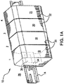
- FIGS 1A - 1E illustrate a fast device replacement (FDR) system of the present invention, generally indicated by reference numeral 10 , as deployed in a DIN rail 14 mounting application.
- FDR fast device replacement
- Several electronic or control devices 18 , 19 , 20 and 21 (collectively indicated by reference numeral 22 ) using the FDR system, are installed on the DIN rail 14 .
- control device will be used hereafter it includes all types of electronic devices that are generally assigned a specific location and are subject to direct replacement.
- DIN rails 14 are generally installed on vertical surfaces, which for the purpose of this discussion will be indicated by reference numeral 26 , such as the back or side walls of an enclosure or on a wall of an electrical closet, control room.
- the DIN rail 14 can be installed directly on a surface 26 of the equipment being controlled by control devices 22 installed on the DIN rail 14 .
- control devices 22 installed on the DIN rail 14 .
- a number of control devices 22 have been installed on DIN rail 14 .
- Indicia placed above the control devices 22 is for the purpose of this discussion, but could be used to easily identify a specific physical location at which individual control devices 22 are located on DIN rail 14 .
- Each control device 22 of the FDR system 10 includes a near field (NFR) reader/writer 30 and each specific physical location associated with a specific one of the control devices 22 includes a NFC tag 38 ( Figure 1B ).
- NFC reader/writer 30 is located on or near a rear surface 34 of each of the control devices 22 .
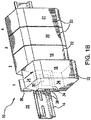
- control device 18 associated with indicia 1 is selected to be replaced. After power to the selected control device 18 has been disconnected the control device 18 can be removed from DIN rail 14 .
- a NFC tag 38 is located either on surface 26 or on DIN rail 14 at a specific physical location associated with control device 18 and indicia 1.
- the NFC tag 38 located at the specific physical location associated with control device 18 can have recently stored information specific to the selected control device 18 being replaced.
- control device 18 has been removed from DIN rail 14 and possible locations for the NFC tag 38 at the specific physical location associated with control device 18 are clearly seen.
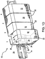
- New control device 42 is being installed to replace control device 18 at the specific physical location associated with control device 18 and indicia 1.
- New control device 42 includes a NFC reader/writer 30 on or near its rear surface 34 .
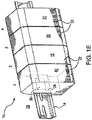
- the new control device 42 has been installed at the specific physical location previously associated with control device 18 and indicia 1, and now being occupied by and associated with new replacement control device 42 .
- the NFC reader/writer 30 in control device 42 will immediately check for information stored on NFC tag 38 located at the specific physical location at which control device 18 was installed and where new control device 42 is currently installed.
- FIG. 2 illustrates the fast device replacement (FDR) system 10 of the present invention, as deployed in a motor control center, enclosed electrical housing or cabinet, generally referred hereafter as an enclosure, and indicated by reference numeral 46 .
- Enclosures 46 are generally provided with racks 50 or trays 54 on which the control devices 22 are assembled.
- Racks 50 are generally open, frame like structures, while trays 54 are more enclosed structures having side walls 58 .
- the control devices 22 are assembled on the racks 50 at specific physical locations.
- the NFC tags 38 can be attached to the inside surface 62 of the enclosure 46 walls at specific physical locations such as R 1 , R 2 , R 3 , L 1 , L 2 and L 3 which coincide with the specific physical locations of the control devices 66 and 70 .
- R 1 , R 2 , R 3 , L 1 , L 2 and L 3 which coincide with the specific physical locations of the control devices 66 and 70 .
- a NFC tag 38 is installed on the surface 62 of the enclosure 46 wall at the specific physical position indicated by indicia R3, such that it will coincide with the specific physical location of control device 66 when rack 50 is in its operating position.
- the specific physical location of a control device 22 is not such that a NFC tag 38 can be placed immediately adjacent to it.
- the specific physical position of control device 70 is such that a NFC tag 38 cannot be positioned to coincide with its specific physical position. Therefore, a remote NFC antenna 74 connected to control device 70 is attached to the rack 50 at a specific physical position that coincides with the specific physical position of NFC tag 38 associated with indicia L3 on inside surface 62 of enclosure 46 when rack 50 is in its operating position.
- the NFC tags 38 can be attached to the insides surfaces 78 of the tray sides 58 at or immediately adjacent the specific physical positions of control devices 22 installed on trays 54 or by using remote NFC antennas 74 .
- the NFC tags 38 can be pre-installed on DIN rails 14 and on the inside surfaces 62 of enclosures and inside surfaces 78 of trays 54 .
- the pre-installed NFC tags 38 can be easily pre-programmed with specific operating parameters and information relative to the particular control device 22 which will be installed at the specific physical location of the particular NFC tag 38 .
- Using pre-installed pre-programmed NFC tags 38 can reduce commissioning time.
- step 100 When power is applied to a control device 22 (step 100) installed in a specific physical location the control device 22 downloads general operating parameters from its local memory (step 105). After the local download is complete its NFC reader/writer 30 initiates contact with a NFC tag 38 associated with the specific physical location in which the control device 22 is installed (step 110). If there is no response from a NFC tag 38 at step 110 the local configuration file is used for operating the control device 22 (step 115). If a NFC tag 38 does respond at step 110 the NFC reader/writer 30 checks to see if there is a configuration file present on the NFC tag 38 (step 120).
- the NFC reader/writer 30 writes the local configuration file to the NFC tag 38 (step 125) and uses the local configuration file for operation of the control device 22 (step 115). If the NFC tag 38 does have a configuration file the NFC tag 38 configuration file is compared to the local configuration file (step130). If the local configuration file is equal to the NFC tag 38 configuration file at step 130 the local configuration file is used for operation of the control device 22 (step 115). If the local configuration file is not equal to the NFC tag 38 configuration file at step 130 the NFC tag 38 configuration file is downloaded (step 135) and used for operating the control device 22 (step 115).
- the NFC reader/writer 30 writes the changed local file to the NFC tag 38 (step 125) and uses the changed local file for operating the control device 22 (step 115).
- the local file and NFC tag 38 file are synchronized each time a change is made to the local file, prior to any planned interruption of operation of the control device 22 and at predetermined intervals. This synchronization ensures that the NFC tag 38 file is current with the local file should any unexpected interruptions occur and if a fast replacement of the control device 22 is required.
Landscapes
- Engineering & Computer Science (AREA)
- Business, Economics & Management (AREA)
- Computer Networks & Wireless Communication (AREA)
- Signal Processing (AREA)
- Economics (AREA)
- Marketing (AREA)
- Tourism & Hospitality (AREA)
- Human Resources & Organizations (AREA)
- Development Economics (AREA)
- Operations Research (AREA)
- Quality & Reliability (AREA)
- Strategic Management (AREA)
- Entrepreneurship & Innovation (AREA)
- Physics & Mathematics (AREA)
- General Business, Economics & Management (AREA)
- General Physics & Mathematics (AREA)
- Theoretical Computer Science (AREA)
- Programmable Controllers (AREA)
- Information Transfer Between Computers (AREA)
Abstract
A system and method for fast device replacement (FDR), where direct replacement of an electronic and/or control device is required with minimum downtime. The electronic or control device to be replaced includes a near field communication (NFC) reader/writer and is located at a specific physical location within the equipment. The system also includes a NFC tag placed at the same specific physical location as the electronic/control device to be replaced. The NFC tag file containing a data parameter set of the electronic/control device most recently associated with the specific physical location. The direct replacement electronic/control device also having a NFC reader/writer and an algorithm for obtaining the NFC tag data parameter set and determining whether to use the data parameter set from the most recent electronic/control device associated with the specific physical location or the local data set of the new direct replacement device.
Description
- The invention is generally related to the replacement of industrial control devices and particularly to rapid replacement of a control device to minimize system down time and device setup time.
- In the past, replacement of an industrial control device has required that the system be shut down for some period of time while the old device is physically removed from its location and the new device is physically installed and configured to operate in the same manner as the replaced device. The configuration can take place before installation, after installation or a combination of both. In any case this can result in a significant amount of nonproductive down time for the system, particularly if the replacement device requires manual configuration. When using a control system connected over a network, after the new device is physically installed and connected to the network it must be enabled, and then settings can be synchronized. Before it can be enabled it must have some method of pre-identifying its network address in the system. Some devices have a dedicated memory module for recording their settings, stored data and operating parameters. When replacement is required the memory module must be removed from the old device and then installed in the new device. Depending on the location and type of memory module this transfer may need to be done before physically installing the new device. Upon startup some additional steps can be required to actually transfer the stored information from the memory module to the new control device. In many processes even a short downtime can be critical to the process being controlled or the equipment used in the process. Therefore, a fast method of replacing a specific control device with an identical control device at the same location, which requires minimal system downtime would be desirable.
- The general idea of Fast Device Replacement (FDR) is to minimize downtime. There are many contributors to downtime; an important one is the transfer of settings and configuration parameters to a new replacement device. The present invention provides a system and method for direct replacement and configuration of a control device with minimal downtime.
- The system of the present invention for fast device replacement comprises:
- a control device having a near field communication (NFC) reader/writer;
- a support structure for supporting the control device at a specific physical location on the support structure;
- a NFC tag attached to the support structure or immediately adjacent the support structure at or immediately adjacent the specific physical location on the support structure supporting the control device; and
- wherein the NFC reader/writer of the control device installed at the specific physical location, upon receiving power, reads stored information specific to the control device installed at the specific physical location from the NFC tag attached at or immediately adjacent the specific physical location.
- The method of the present invention comprises:
- providing a support structure having a specific location for supporting a control device;
- attaching a near field communication (NFC) tag on or immediately adjacent the support structure at or immediately adjacent the specific location for supporting the control device;
- installing a control device having a NFC reader/writer at the specific location for supporting a control device;
- applying power to the control device installed at the specific location; and
- reading, from the NFC tag attached at or immediately adjacent the specific location, by the NFC reader/writer of the control device installed at the specific location, stored information related to the control device installed at the specific location.
-
-
Figures 1A - 1E illustrate a DIN rail installation with NFC tags installed. -
Figure 2 illustrates a control center with NFC tags installed. -
Figure 3 is a flow chart showing the steps for rapid replacement of control devices using the method of the present invention. -
Figures 1A - 1E illustrate a fast device replacement (FDR) system of the present invention, generally indicated byreference numeral 10, as deployed in aDIN rail 14 mounting application. Several electronic orcontrol devices DIN rail 14. It is to be understood that although the term "control device" will be used hereafter it includes all types of electronic devices that are generally assigned a specific location and are subject to direct replacement.DIN rails 14 are generally installed on vertical surfaces, which for the purpose of this discussion will be indicated byreference numeral 26, such as the back or side walls of an enclosure or on a wall of an electrical closet, control room. In some applications theDIN rail 14 can be installed directly on asurface 26 of the equipment being controlled bycontrol devices 22 installed on theDIN rail 14. As can be seen inFigure 1A , a number ofcontrol devices 22 have been installed onDIN rail 14. Indicia placed above thecontrol devices 22 is for the purpose of this discussion, but could be used to easily identify a specific physical location at whichindividual control devices 22 are located onDIN rail 14. Eachcontrol device 22 of theFDR system 10 includes a near field (NFR) reader/writer 30 and each specific physical location associated with a specific one of thecontrol devices 22 includes a NFC tag 38 (Figure 1B ). In this particular embodiment the NFC reader/writer 30 is located on or near arear surface 34 of each of thecontrol devices 22. - Referring now to
Figure 1B ,control device 18 associated withindicia 1 is selected to be replaced. After power to theselected control device 18 has been disconnected thecontrol device 18 can be removed fromDIN rail 14. ANFC tag 38 is located either onsurface 26 or onDIN rail 14 at a specific physical location associated withcontrol device 18 andindicia 1. TheNFC tag 38 located at the specific physical location associated withcontrol device 18 can have recently stored information specific to theselected control device 18 being replaced. InFigure 1C control device 18 has been removed fromDIN rail 14 and possible locations for theNFC tag 38 at the specific physical location associated withcontrol device 18 are clearly seen. - Referring now to
Figure 1D , a new exactreplacement control device 42 is being installed to replacecontrol device 18 at the specific physical location associated withcontrol device 18 andindicia 1.New control device 42 includes a NFC reader/writer 30 on or near itsrear surface 34. - Referring now to
Figure 1E , thenew control device 42 has been installed at the specific physical location previously associated withcontrol device 18 andindicia 1, and now being occupied by and associated with newreplacement control device 42. When power is reconnected to controldevice 42 the NFC reader/writer 30 incontrol device 42 will immediately check for information stored onNFC tag 38 located at the specific physical location at whichcontrol device 18 was installed and wherenew control device 42 is currently installed. -
Figure 2 illustrates the fast device replacement (FDR)system 10 of the present invention, as deployed in a motor control center, enclosed electrical housing or cabinet, generally referred hereafter as an enclosure, and indicated byreference numeral 46.Enclosures 46 are generally provided withracks 50 ortrays 54 on which thecontrol devices 22 are assembled.Racks 50 are generally open, frame like structures, whiletrays 54 are more enclosed structures havingside walls 58. Thecontrol devices 22 are assembled on theracks 50 at specific physical locations. Whenracks 50 are used theNFC tags 38 can be attached to theinside surface 62 of theenclosure 46 walls at specific physical locations such as R1, R2, R3, L1, L2 and L3 which coincide with the specific physical locations of thecontrol devices Fig. 2 , aNFC tag 38 is installed on thesurface 62 of theenclosure 46 wall at the specific physical position indicated by indicia R3, such that it will coincide with the specific physical location ofcontrol device 66 whenrack 50 is in its operating position. In some situations the specific physical location of acontrol device 22 is not such that aNFC tag 38 can be placed immediately adjacent to it. The specific physical position ofcontrol device 70 is such that aNFC tag 38 cannot be positioned to coincide with its specific physical position. Therefore, aremote NFC antenna 74 connected tocontrol device 70 is attached to therack 50 at a specific physical position that coincides with the specific physical position ofNFC tag 38 associated with indicia L3 oninside surface 62 ofenclosure 46 whenrack 50 is in its operating position. - When
trays 54 are used theNFC tags 38 can be attached to theinsides surfaces 78 of thetray sides 58 at or immediately adjacent the specific physical positions ofcontrol devices 22 installed ontrays 54 or by usingremote NFC antennas 74. - If the specific physical location of
control devices 22 can be accurately determined theNFC tags 38 can be pre-installed onDIN rails 14 and on theinside surfaces 62 of enclosures and insidesurfaces 78 oftrays 54. Thepre-installed NFC tags 38 can be easily pre-programmed with specific operating parameters and information relative to theparticular control device 22 which will be installed at the specific physical location of theparticular NFC tag 38. Using pre-installed pre-programmedNFC tags 38 can reduce commissioning time. - Referring now to the FDR flow chart of
Figure 3 , a more detailed description of the FDR system interactions between theNFC tag 22 andcontrol device 22 is described. When power is applied to a control device 22 (step 100) installed in a specific physical location thecontrol device 22 downloads general operating parameters from its local memory (step 105). After the local download is complete its NFC reader/writer 30 initiates contact with aNFC tag 38 associated with the specific physical location in which thecontrol device 22 is installed (step 110). If there is no response from aNFC tag 38 atstep 110 the local configuration file is used for operating the control device 22 (step 115). If aNFC tag 38 does respond atstep 110 the NFC reader/writer 30 checks to see if there is a configuration file present on the NFC tag 38 (step 120). If theNFC tag 38 does not have a configuration file atstep 120 the NFC reader/writer 30 writes the local configuration file to the NFC tag 38 (step 125) and uses the local configuration file for operation of the control device 22 (step 115). If theNFC tag 38 does have a configuration file theNFC tag 38 configuration file is compared to the local configuration file (step130). If the local configuration file is equal to theNFC tag 38 configuration file atstep 130 the local configuration file is used for operation of the control device 22 (step 115). If the local configuration file is not equal to theNFC tag 38 configuration file atstep 130 theNFC tag 38 configuration file is downloaded (step 135) and used for operating the control device 22 (step 115). During operation of thecontrol device 22, if there is a configuration change to the local file from the network (step 140) the NFC reader/writer 30 writes the changed local file to the NFC tag 38 (step 125) and uses the changed local file for operating the control device 22 (step 115). The local file andNFC tag 38 file are synchronized each time a change is made to the local file, prior to any planned interruption of operation of thecontrol device 22 and at predetermined intervals. This synchronization ensures that theNFC tag 38 file is current with the local file should any unexpected interruptions occur and if a fast replacement of thecontrol device 22 is required.
Claims (8)
1. A system for fast device replacement, comprising:
a control device having a near field communication (NFC) reader/writer;
a support structure for supporting the control device at a specific physical location on the support structure; and
a NFC tag attached to the support structure or immediately adjacent the support structure at or immediately adjacent the specific physical location on the support structure supporting the control device; and
wherein the NFC reader/writer of the control device installed at the specific physical location, upon receiving power, reads stored information related to the control device installed at the specific physical location from the NFC tag attached at or immediately adjacent the specific physical location. 2. The system for fast device replacement of claim 1, wherein the support structure can be a control rack, a DIN rail, an enclosure wall or an equipment surface.
3. The system for fast device replacement of claim 1, wherein the NFC reader/writer of the control device installed at the specific physical location, upon receiving a network change to stored information specific to the control device installed at the specific location, writes the new information to the NFC tag attached at or immediately adjacent the specific physical location.
4. The system for fast device replacement of claim 1, wherein the NFC reader/writer of the control device installed at the specific physical location, upon receiving a notice of a planned interruption of operation, writes its current information specific to the control device installed at the specific location to the NFC tag attached at or immediately adjacent the specific physical location.
5. The system for fast device replacement of claim 1, wherein the NFC reader/writer of the control device installed at the specific physical location, at predetermined intervals, synchronizes its current information specific to the control device installed at the specific location with the NFC tag attached at or immediately adjacent the specific physical location.
6. The system for fast device replacement of claim 1, wherein a pre-installed pre-programmed NFC tag can be used to commission a new control device being installed at the specific physical location on the support structure.
8. A method for fast device replacement, comprising:
providing a support structure having a specific location for supporting a control device;
attaching a near field communication (NFC) tag on or immediately adjacent the support structure at or immediately adjacent the specific location for supporting the control device;
installing a control device having a NFC reader/writer at the specific location for supporting a control device;
applying power to the control device installed at the specific location; and
reading, from the NFC tag attached at or immediately adjacent the specific location, by the NFC reader/writer of the control device installed at the specific location, stored information related to the control device installed at the specific location.
9. The method of claim 10, wherein the NFC reader/writer writes information related to the control device installed at the specific physical location to the NFC tag attached at or immediately adjacent the specific physical location.
Applications Claiming Priority (1)
| Application Number | Priority Date | Filing Date | Title |
|---|---|---|---|
| US14/976,116 US20170180007A1 (en) | 2015-12-21 | 2015-12-21 | Fast device replacement system |
Publications (1)
| Publication Number | Publication Date |
|---|---|
| EP3185192A1 true EP3185192A1 (en) | 2017-06-28 |
Family
ID=57681252
Family Applications (1)
| Application Number | Title | Priority Date | Filing Date |
|---|---|---|---|
| EP16203378.1A Withdrawn EP3185192A1 (en) | 2015-12-21 | 2016-12-12 | Fast device replacement system |
Country Status (3)
| Country | Link |
|---|---|
| US (1) | US20170180007A1 (en) |
| EP (1) | EP3185192A1 (en) |
| CN (1) | CN107026751A (en) |
Families Citing this family (2)
| Publication number | Priority date | Publication date | Assignee | Title |
|---|---|---|---|---|
| CN110550069B (en) * | 2018-06-01 | 2020-11-06 | 比亚迪股份有限公司 | Data transmission method, device and system for rail transit vehicle |
| ES1307061Y (en) * | 2023-09-01 | 2024-07-19 | Delphine Hatsadourian | TIMER DEVICE TO ENCOURAGE WATER SAVING IN THE SHOWER |
Citations (3)
| Publication number | Priority date | Publication date | Assignee | Title |
|---|---|---|---|---|
| US20090091442A1 (en) * | 2007-10-04 | 2009-04-09 | Cisco Technology, Inc. A Corporation Of California | Inventory devices and methods |
| DE102013220434A1 (en) * | 2013-10-10 | 2015-04-16 | Robert Bosch Gmbh | Transceiver system for a component, component with a transceiver system and component system, and method for operating a transceiver system |
| US20150235067A1 (en) * | 2009-08-05 | 2015-08-20 | Dieter Kilian | Receiving device with rfid detection of built-in components held therein, and rfid detection method |
-
2015
- 2015-12-21 US US14/976,116 patent/US20170180007A1/en not_active Abandoned
-
2016
- 2016-12-08 CN CN201611121285.XA patent/CN107026751A/en active Pending
- 2016-12-12 EP EP16203378.1A patent/EP3185192A1/en not_active Withdrawn
Patent Citations (3)
| Publication number | Priority date | Publication date | Assignee | Title |
|---|---|---|---|---|
| US20090091442A1 (en) * | 2007-10-04 | 2009-04-09 | Cisco Technology, Inc. A Corporation Of California | Inventory devices and methods |
| US20150235067A1 (en) * | 2009-08-05 | 2015-08-20 | Dieter Kilian | Receiving device with rfid detection of built-in components held therein, and rfid detection method |
| DE102013220434A1 (en) * | 2013-10-10 | 2015-04-16 | Robert Bosch Gmbh | Transceiver system for a component, component with a transceiver system and component system, and method for operating a transceiver system |
Non-Patent Citations (1)
| Title |
|---|
| WANT R: "Near field communication", IEEE PERVASIVE COMPUTING, IEEE SERVICE CENTER, LOS ALAMITOS, CA, US, vol. 10, no. 3, 1 July 2011 (2011-07-01), pages 4 - 7, XP011442352, ISSN: 1536-1268, DOI: 10.1109/MPRV.2011.55 * |
Also Published As
| Publication number | Publication date |
|---|---|
| CN107026751A (en) | 2017-08-08 |
| US20170180007A1 (en) | 2017-06-22 |
Similar Documents
| Publication | Publication Date | Title |
|---|---|---|
| CN105122156B (en) | A kind of electric interfaces module | |
| US20170064860A1 (en) | Method and System for Automatic Location Tracking of Information Technology Components in a Data Center | |
| US9875207B2 (en) | Remote terminal unit (RTU) hardware architecture | |
| EP1298974A3 (en) | Method and apparatus for providing a common support services infrastructure for a network element | |
| WO2015148929A1 (en) | Configuring lighting electronics using database and mobile device | |
| CN107360014A (en) | Intelligent management terminal, intelligent Optical Distribution Network equipment and its management method and system | |
| US20120162910A1 (en) | Data processing apparatus and power connection mechanism and method thereof | |
| CN1629961B (en) | Method of using GPS in an automated data repository and system for providing location information | |
| US20170180007A1 (en) | Fast device replacement system | |
| WO2005098558A1 (en) | Closed-loop reel setup verification and traceability | |
| US10037446B2 (en) | Electrical interface module | |
| CN104079631A (en) | Version management method and related device | |
| US9461715B1 (en) | Physical server location identification | |
| KR102082055B1 (en) | Smart rack for total system | |
| CN101159606A (en) | Method and network device for solving address conflict | |
| US10165390B2 (en) | Methods, systems, and computer readable media for management of passive network taps using radio frequency identification (RFID) | |
| JP6423428B2 (en) | Method and apparatus for storing equalizer settings in an active speaker | |
| EP3129960B1 (en) | Apparatus, system, and methods for retrofitting vending systems with wireless communication | |
| US20150062833A1 (en) | Mechanical assembly and method to provide form-factor and wire alike adaptation of existing platform hardware modules into new products | |
| KR102739891B1 (en) | Vehicle and controlling method thereof | |
| CN110167139B (en) | Positioning method and device | |
| US10008245B1 (en) | Positioning components in a rack to permit base plane access | |
| CN107515838B (en) | Configuration allocation | |
| JP2017069668A (en) | Information processing device | |
| KR101377546B1 (en) | Smart rack door opening apparatus and method, and method for setting door opening apparatus thereof |
Legal Events
| Date | Code | Title | Description |
|---|---|---|---|
| PUAI | Public reference made under article 153(3) epc to a published international application that has entered the european phase |
Free format text: ORIGINAL CODE: 0009012 |
|
| STAA | Information on the status of an ep patent application or granted ep patent |
Free format text: STATUS: THE APPLICATION HAS BEEN PUBLISHED |
|
| AK | Designated contracting states |
Kind code of ref document: A1 Designated state(s): AL AT BE BG CH CY CZ DE DK EE ES FI FR GB GR HR HU IE IS IT LI LT LU LV MC MK MT NL NO PL PT RO RS SE SI SK SM TR |
|
| AX | Request for extension of the european patent |
Extension state: BA ME |
|
| STAA | Information on the status of an ep patent application or granted ep patent |
Free format text: STATUS: THE APPLICATION IS DEEMED TO BE WITHDRAWN |
|
| 18D | Application deemed to be withdrawn |
Effective date: 20180103 |