EP3184963A1 - Apparatus and method for magnetic field map generation for indoor localization - Google Patents
Apparatus and method for magnetic field map generation for indoor localization Download PDFInfo
- Publication number
- EP3184963A1 EP3184963A1 EP15307120.4A EP15307120A EP3184963A1 EP 3184963 A1 EP3184963 A1 EP 3184963A1 EP 15307120 A EP15307120 A EP 15307120A EP 3184963 A1 EP3184963 A1 EP 3184963A1
- Authority
- EP
- European Patent Office
- Prior art keywords
- mobile device
- magnetic field
- information
- map
- user
- Prior art date
- Legal status (The legal status is an assumption and is not a legal conclusion. Google has not performed a legal analysis and makes no representation as to the accuracy of the status listed.)
- Withdrawn
Links
Images


Classifications
-
- G—PHYSICS
- G01—MEASURING; TESTING
- G01C—MEASURING DISTANCES, LEVELS OR BEARINGS; SURVEYING; NAVIGATION; GYROSCOPIC INSTRUMENTS; PHOTOGRAMMETRY OR VIDEOGRAMMETRY
- G01C21/00—Navigation; Navigational instruments not provided for in groups G01C1/00 - G01C19/00
- G01C21/20—Instruments for performing navigational calculations
- G01C21/206—Instruments for performing navigational calculations specially adapted for indoor navigation
-
- H—ELECTRICITY
- H04—ELECTRIC COMMUNICATION TECHNIQUE
- H04W—WIRELESS COMMUNICATION NETWORKS
- H04W4/00—Services specially adapted for wireless communication networks; Facilities therefor
- H04W4/02—Services making use of location information
- H04W4/029—Location-based management or tracking services
-
- H—ELECTRICITY
- H04—ELECTRIC COMMUNICATION TECHNIQUE
- H04W—WIRELESS COMMUNICATION NETWORKS
- H04W4/00—Services specially adapted for wireless communication networks; Facilities therefor
-
- H—ELECTRICITY
- H04—ELECTRIC COMMUNICATION TECHNIQUE
- H04W—WIRELESS COMMUNICATION NETWORKS
- H04W4/00—Services specially adapted for wireless communication networks; Facilities therefor
- H04W4/02—Services making use of location information
- H04W4/025—Services making use of location information using location based information parameters
- H04W4/026—Services making use of location information using location based information parameters using orientation information, e.g. compass
-
- H—ELECTRICITY
- H04—ELECTRIC COMMUNICATION TECHNIQUE
- H04W—WIRELESS COMMUNICATION NETWORKS
- H04W4/00—Services specially adapted for wireless communication networks; Facilities therefor
- H04W4/30—Services specially adapted for particular environments, situations or purposes
- H04W4/33—Services specially adapted for particular environments, situations or purposes for indoor environments, e.g. buildings
-
- H—ELECTRICITY
- H04—ELECTRIC COMMUNICATION TECHNIQUE
- H04W—WIRELESS COMMUNICATION NETWORKS
- H04W4/00—Services specially adapted for wireless communication networks; Facilities therefor
- H04W4/02—Services making use of location information
- H04W4/025—Services making use of location information using location based information parameters
- H04W4/027—Services making use of location information using location based information parameters using movement velocity, acceleration information
-
- H—ELECTRICITY
- H04—ELECTRIC COMMUNICATION TECHNIQUE
- H04W—WIRELESS COMMUNICATION NETWORKS
- H04W4/00—Services specially adapted for wireless communication networks; Facilities therefor
- H04W4/80—Services using short range communication, e.g. near-field communication [NFC], radio-frequency identification [RFID] or low energy communication
Definitions
- the present principles relate to a system and a method for generating a magnetic map, and more particularly, to a system and a method for crowd generation of a magnetic map for indoor localization.
- RF Fingerprint One example of technology for indoor localization is based on an "RF Fingerprint" and requires a minimal dedicated infrastructure.
- the technology is based on the use of multiple radios, embedded in mobile terminals (such as WiFi, Bluetooth, broadcast, etc.) for localization.
- the RF fingerprint technique suffers from two fundamental drawbacks - it requires a heavy measurement campaign to construct the radio map database with the right granularity, which is time consuming and not very user friendly for a consumer application, and the radio map evolves with time.
- the short time instability of the radio map is due to the well-known instability of the RSSI (Received Signal Strength Indicator) signal resulting from the small scale multipath fading, while the mid/long term instability is due to the change in the number and location of the active radio transmitters. This is particularly true for WiFi transmitters.
- RSSI Receiveived Signal Strength Indicator
- the ambient magnetic field instead of the RF electric field, as a localization fingerprint.
- the "magnetic fingerprint” method takes advantage of the distortions of the earth's magnetic field (also called a geomagnetic field), at a given location, introduced by the ferromagnetic parts of the building structure and any ferromagnetic objects to infer the user's location.
- the ambient magnetic field can be measured by the magnetometer embedded in mobile devices and compared with a magnetic field map that has been created in advance for the building.
- it still requires a lot of time and effort to generate the initial magnetic field map of each building.
- the present principles provide indoor localization capabilities based on magnetic fingerprint technology.
- User friendly techniques are incorporated for collaboratively and progressively generating an indoor map of an ambient magnetic field that can then be utilized by a localization method.
- the magnetic field map is constructed by one or more authorized users using magnetometers embedded in their mobile devices. This permits a continuous refreshment of a magnetic field fingerprint database without regular survey/updates required except for significant interior changes like, for example, moving large metallic objects and furniture that may induce an important change in the magnetic field distribution.
- the present principles also offer a certain degree of privacy and reliability since only authorized users are allowed to participate and only the locations where the user might be are mapped.
- One embodiment includes an apparatus for magnetic map information gathering comprising a means for displaying an architectural plan on a mobile device according to an orientation of the mobile device, a means for receiving an indication of a position of a mobile device user on the architectural plan, a means for obtaining a scale of the displayed architectural plan in response to the received indication, a means for obtaining ambient magnetic field information associated with the indicated position, a means for obtaining identification information of a mobile device or user, and a means for transmitting the indicated position, scale, ambient magnetic field information and identification information to a server.
- Alternative embodiments can also include a means for displaying an indicator of a user's orientation on the architectural plan.
- the identification information of the mobile device can a media access control MAC address in some embodiments.
- inventions can include at least one of a means for receiving and a means for transmitting that includes at least one of a wired communication means and a wireless communication means. Still yet other embodiments can also include a means for accepting an indication of position when at least one wall displayed on the architectural plan is parallel to at least one side of the mobile device and/or a means for receiving an updated magnetic field map for localization from a server.
- Alternative embodiments can also include using a media access control MAC address as identification information for the mobile device, accepting an indication of position when at least one wall displayed on the architectural plan is parallel to at least one side of the mobile device, displaying an indicator of a user's orientation on the architectural plan and/or receiving an updated magnetic field map for localization from a server.
- the embodiments can be further refined wherein at least one of the receiving of the architectural plan and the transmitting of information is accomplished over a wired communication means.
- Additional embodiments can also include a method for generating a magnetic map comprising receiving indicated position, scale, ambient magnetic field information and identification information, determining a geographic volume based on the indicated position and scale, averaging the magnetic field information with prior measurements associated with the indicated position and associated to geometrical points inside the determined geographical volume, determining new values for magnetic field information and validating values for localization use when a number of prior measurements approximate a current location estimation.
- Alternative embodiments can include transmitting an updated magnetic field map for localization to a mobile device.
- Additional embodiments can include an apparatus for generating a magnetic map comprising a means for receiving indicated position, scale, ambient magnetic field information and identification information, a means for determining a geographic volume based on the indicated position and scale, a means for averaging the magnetic field information with prior measurements associated with the indicated position and associated to all geometrical points inside the determined geographic volume, a means for determining new values for magnetic field information and a means for validating values for localization use when a number of prior measurements approximate a current location estimation.
- One way to reduce the required effort for generating a magnetic field map of a building is to do it collaboratively by using magnetometers embedded in mobile devices of different users (e.g., home family members, company employees and/or volunteers among store customers, etc.).
- This type of "crowd sourcing" or collaborative effort of magnetic field map building raises the issue of the reliability of the collected data, mainly due to the fact that the data can be collected by nonprofessional users who are more or less engaged in other activities; the variability between the sensors used in different mobile devices; and/or the short/long term time instability of a measured magnetic field.
- the localization of a user during a mapping phase should be simple, user friendly and easy to handle by a nonprofessional user who is not necessarily aware about the technology behind it.
- the accuracy of the measured magnetic field should be coherent with the localization accuracy that should be inferred by a measurement system.
- the effectiveness of the localization method based on the magnetic field map requires measuring the three components of the magnetic field which depends on the orientation of a mobile device. Therefore, a simple and intuitive way of orienting the mobile device during the mapping phase should be used.
- the present principles provide alternative collaborative (crowd sourcing) techniques for generating an indoor map of an ambient magnetic field that is well suited for magnetic fingerprint localization processes.
- the techniques take advantage of the characteristics of a magnetic field.
- the present principles can utilize apparatus that include, for example, mobile devices with magnetometers to help gather magnetic field information.
- "Authorized" users e.g., family members, etc.
- "Authorized” users typically share an architectural plan with rooms including an arrangement of the main furniture, such as, for example, tables, armchairs, sofas, major home appliances, etc.
- authorization for example, can be based on users who are residents or permitted to use a location associated with the architectural plan.
- Pre-screening of users prevents unqualified users from corrupting gathered data through incorrect readings and/or through intentional misuse of apparatus for gathering the data.
- Users who lack a tie to a particular location might also only frequent the location on rare occasions and provide little data for evaluation. They would also lack any interest in using the data and might not be as diligent as a
- FIG. 1 an example collaborative magnetic field map generation apparatus 100 is shown in accordance with an embodiment of the present principles.
- the apparatus 100 in this example is a mobile device 102 with a display or screen 104.
- the mobile device 102 can be, for example, a smartphone, a tablet and/or any type of mobile device that allows user interaction and the like.
- the display 104 can be, for example, a touch screen meant for use by touching the display 104 with a finger and the like by a user and/or the display 104 can be a screen that uses a writing instrument such as a stylus and the like to write and/or make selections on the screen.
- the method of input to the apparatus 100 is not limited to these two types of displays. For example, there can also be a pointer that is controlled via a remote mouse and/or keys on the apparatus 100 that a permit a user to make/indicate a selection on a display/screen.
- the illustrated example of apparatus 100 is comprised of a magnetic field information manager 106 which manages capturing of magnetic field information, timing information, user and/or mobile identification (ID) information, architectural plan information and input/output information, etc.
- the apparatus 100 includes a wireless communication means 108 that can include, for example, WiFi, Bluetooth, etc. (includes short and/or long range wireless communication means).
- the apparatus 100 typically has an embedded magnetometer 110, gyroscope 112 and/or accelerometer 116.
- the magnetometer 110, gyroscope 112 and accelerometer 116 are not required to be embedded in the mobile device and can be externally attached to the apparatus 100.
- the attachment is typically accomplished such that movement of the apparatus 100 causes similar movement of the magnetometer 110, gyroscope 112 and/or accelerometer 116.
- the apparatus 100 can also include a memory 114 for storing information such as, for example, magnetic field information, timing information, authorization information, indicated location information, orientation information and/or mobile device/user ID information and the like.
- the apparatus 200 includes a magnetic field information manager 202 comprised of an architectural map interface 204.
- the architectural map interface 204 becomes operational, for example, when an authorization code 210 is present and correct.
- the architectural map interface 204 includes a map renderer 206 and an input interface 208.
- the map renderer 206 supplies an architectural map to a mobile device display.
- the architectural map is typically received from a server 222 via wired and/or wireless communication means.
- Orientation information associated with a mobile device can be received from a gyroscope 218 and/or accelerometer 224 to facilitate in correctly rendering the architectural plan on the mobile device display by the map renderer 206.
- the map renderer 206 also renders different versions of the architectural map based upon inputs from the input interface 208. Such inputs can include, but are not limited to, floor selection, room selection, area selection and/or zoom (i.e., scale) selection and the like.
- the input interface 208 allows input from the mobile device to be utilized by the architectural map interface 204.
- the input interface 208 can accept key/button hardware selections, soft key selections, stylus type screen inputs and/or user touch selections and the like.
- the input interface 208 is typically responsible for receiving indicated position information initiated by a user 220 of a mobile device.
- the magnetic information manager 202 When an input is received by the input interface 208, the magnetic information manager 202 records magnetic field information from the magnetometer 216 along with timing information.
- the authorization code 210 can also contain a user ID and/or a mobile device ID that can be included along with information transmitted by the magnetic field information manager 202.
- the user ID and/or mobile ID can also be received directly from the user 220 (e.g., typed in, scanned in and/or otherwise input into the mobile device, etc.) and/or from a mobile device itself (e.g., data that was entered previously, etc. like owner information and/or a unique media access control (MAC) address, etc.).
- MAC media access control
- the magnetic field information manager 202 can send information autonomously (i.e., without request, at timed intervals and/or only under certain conditions, etc.) and/or only when requested by server 222. Information transfer can also be initiated when a physical connection is made (e.g., when a mobile device is placed in a docking station and/or cable plugged in, etc.).
- An authorized user can at any time decide to run an application such as a magnetic field information manager 106/202 on their mobile device which displays the architectural plan.
- the application allows the authorized user to indicate their position in a user-friendly manner - for example, in a living room, sitting on a sofa in front of a television, in a kitchen in front of a refrigerator, etc.
- the application can also provide a zooming or scaling capability that includes at least a part of the map with a user position and, in one embodiment, includes at least two perpendicular walls which are used for helping the user in the estimation of their location.
- a pointer or other indicator e.g., arrow head
- the orientation of a mobile device is utilized such that a user, depicted on the map, is displayed by the mobile device facing (oriented) in the same direction as in the real world (the most intuitive map orientation) and the sides of the mobile device are parallel to the displayed location walls (e.g., when the location is assumed to be of a rectangular shape).
- a set of measurements of the three components of the magnetic field vector at the indicated location is obtained using, for example, a magnetometer embedded in a mobile device.
- the vector of the three magnetic field components along with an associated accuracy provided by a zoom/scale factor of a displayed architectural plan, a mobile device/user identifier and time stamps corresponding to each magnetic field are sent to a central server (e.g., a gateway and the like, a locally or remotely located server, etc.) using a wired and/or wireless communication means available to the mobile device (e.g., cable connection, docking station, WiFi, Bluetooth, etc.).
- a central server e.g., a gateway and the like, a locally or remotely located server, etc.
- a wired and/or wireless communication means available to the mobile device (e.g., cable connection, docking station, WiFi, Bluetooth, etc.).
- the data received is used for updating a magnetic field map under construction.
- the indicated location and associated zoom/scale defines a geographic volume according to a predefined formula.
- the value of each magnetic field component (in an absolute reference) averaged over the set of measurements associated with the indicated position is associated to all the geometrical points (with the finest granularity) inside the volume defined by the position, with an accuracy defined by the zoom factor (scale).
- a new value of the three magnetic field components, associated to each geometrical point (with the finest granularity) is calculated taking into account the previous value and the accuracies of the previous and the new values according to a defined formula.
- the user position can be estimated utilizing a localization process that can be hosted on a server, such as the gateway, which fundamentally analyzes the similarities between the current measurement of the magnetic field components at the given location and those stored so far in the magnetic field map under construction before updating.
- the estimated location is then compared with the received position validated by the user with its associated accuracy.
- the actual position i.e., a position indicated by an authorized user during the map building phase
- the map is considered ready for use as it is by the localization process for that localization.
- the application can be downloaded by mobile devices for running a localization application on a mobile device when, for example, a wired and/or wireless link between the mobile device and the server is not available.
- the application can also run even with a wired and/or wireless link between the mobile device and a server.
- the continuously refreshed magnetic field map at the server side can be downloaded to the mobile device of an authorized user at their request and/or automatically (without a user initiated request).
- Main updates of the magnetic map, stored in the mobile device can be done regularly and, for example, at the occasion of significant changes, such as home equipment refurbishment, etc.
- a user from an "authorized” list of users who has previously registered their mobile device with the server, etc. and shared an architectural plan of a home or other structure with different parts/rooms including the arrangement of large objects (e.g., the main furniture, such as tables, armchairs, sofas, major home appliances, etc.) can, at any time, run a "magnetic-crowd-mapping" application on their mobile device, which displays the architectural plan.
- the user utilizes the architectural plan to indicate their position with the accuracy allowed by the architectural plan and a zoom factor k Zoom (scale).
- FIG. 3 an example zoom or scaling operation 300 on a mobile device 302a, 302b, 302c is illustrated in accordance with an embodiment of the present principles.
- the zooming/scaling operation allows a part 306 of an architectural map 304 including a user position 308 and, according to one embodiment, at least two walls 310 which can be used for helping the user in the estimation of their position.
- Mobile device 302a illustrates a list of architecture plans that a user can select.
- Mobile device 302b illustrates an architectural floor plan of the selected architecture plan.
- Mobile device 302c illustrates a selected room from the architectural floor plan (finest granularity or largest zoom factor).
- FIG. 4 an example locating operation 400 on mobile devices 402-406 is shown in accordance with an embodiment of the present principles.
- pointers 408-412 are moved in a map, their relative distances to the two closest walls is displayed helping users 416-420 to assess their position.
- the users 416-420 are seated in a room 414.
- each user 416-420 is oriented differently in the room. This is evident, for example, where user 416 has the mobile device 402 which shows him located by pointer 408.
- User 418 has the mobile device 404 which shows him located by pointer 410.
- User 420 has the mobile device 406 which shows him located by pointer 412.
- FIG. 5 an example orienting operation 500 on a mobile device is shown in accordance with an embodiment of the present principles.
- the orientation of a mobile device 502 is such that a user 504 depicted in a map 506 (i.e., architectural plan) displayed by the mobile device 502 is facing in the same direction as in the real world (the most intuitive map orientation) and sides 508-514 of the mobile device 502 (e.g., assumed to be a rectangular shape) are parallel to location displayed walls 516-522 (e.g., the location is assumed, for this example, to be a rectangular shape).
- a map 506 i.e., architectural plan
- sides 508-514 of the mobile device 502 e.g., assumed to be a rectangular shape
- location displayed walls 516-522 e.g., the location is assumed, for this example, to be a rectangular shape.
- a mobile device 526 depicts the orientation/position of a first user with an orientation/position indicator 528
- a mobile device 530 depicts the orientation/position of a second user with an orientation/position indicator 532
- a mobile device 534 depicts the orientation/position of a third user with an orientation/position indicator 536 in the same room.
- FIG. 6 an example coordinate system determination 600 for a mobile device 602 is illustrated in accordance with an embodiment of the present principles.
- FIG. 6 an example coordinate system determination 600 for a mobile device 602 is illustrated in accordance with an embodiment of the present principles.
- FIG. 6 shows the relation between a coordinate system 604 of a mobile device 602 and a coordinate system of a physical location, (e.g., the room 606 or a building 608).
- the three components of a magnetic field measured by a mobile device can be expressed in an absolute reference which is independent from a mobile device orientation using the corresponding rotation and translation matrices.
- the rotation matrix can be expressed as the multiplication of three basic rotations.
- R x ( ⁇ ) is the clockwise rotation, about the x-axis, by an angle ⁇ .
- R y ( ⁇ ) is the clockwise rotation, about the y-axis, by an angle ⁇ .
- R z ( ⁇ ) is the clockwise rotation, about the z-axis, by an angle ⁇ .
- FIG. 7 an example 700 of rotational effects on a coordinate system 704 for a mobile device 702 is depicted in accordance with an embodiment of the present principles.
- a set of N measurements of the three components of a magnetic field vector at an indicated location 706 is used (where N is a positive integer greater than 30 to smooth the inherent measurement errors).
- a tuple 708 constituted of: the vector with the three magnetic field components ( B x , B y , B z ) measured by the three-axis magnetometer of a mobile device (i.e., components in the local mobile device reference ( i,j,k ) 704), a validated location given by the three coordinates ( X, Y, Z ) 710 in an absolute reference ( I, J, K ) and associated accuracy provided by a zoom/scale factor k Zoom of the displayed plan, together with a mobile device/user identifier (ID) and a time stamp ( t ) corresponding to a magnetic field record, is sent to a server (which can be, for example, a gateway and/or other local or remotely located server) using a wired and/or wireless communication system available in the mobile device 702 (e.g., cable, WiFi, Bluetooth, etc.).
- a server which can be, for example, a gateway and/or other local or remotely located server
- FIG. 8 an example 800 of a data format 802 for a mobile device is shown in accordance with an embodiment of the present principles.
- the received data at the server side is first transformed into an absolute reference and then used for updating a magnetic field map under construction.
- An indicated position and an associated zoom factor k Zoom i.e., a positive integer scaling factor
- V a geographic volume
- k Zoom 1
- scale scale of the architectural plan.
- ⁇ Max a spatial resolution corresponding to the largest uncertainty ⁇ Max
- FIG. 9 depicts a geometrical volume definition 900 in accordance with an embodiment of the present principles.
- V is the volume of a parallelepiped 902 centered on P ( X, Y, Z ) with a square section 904 of 2 ⁇ side and a height 906 of, for example, 1m (typically a value between 0.8m and 1.2m, corresponding to the height position of a mobile device held by a user, but it can be any value).
- the magnetic field is assumed to be invariant along the defined Z interval.
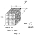
- an example 1000 of a volume filling 1002 based on a finest spatial granularity 1004 is illustrated in accordance with an embodiment of the present principles.
- a new value of the three magnetic field components [( B x , B y , B z )] associated to each geometrical point (with the finest granularity) is calculated taking into account the previous value [( B x , B y , B z )] n -1 and the just received value [( B x , B y , B z )] n and their associated uncertainties (respectively ⁇ n -1 and ⁇ n ) according to a defined formula.
- B x n A n + / - ⁇ n ; where A n is the average of the K values of the magnetic field components B x measured by the mobile device at the indicated location and ⁇ n is the Standard Deviation (SD) of the measured K values.
- SD Standard Deviation
- FIG. 11 an example 1100 (for Measurement1) of building a magnetic field map 1102 in accordance with an embodiment of the present principles.
- the magnetic field map 1102 building (in two dimensions for clarity; the z axis is not taken into account over which the magnetic field is assumed to be invariant) for two successive measurements: Measurement 1 (shown in FIG. 11 ) and Measurement 2 (shown in FIG. 12 ) done around the same area with two different zoom factors (scaling factors): ( k Zoom ) 1 and ( k Zoom ) 2 and two different accuracies: ⁇ 1 and ⁇ 2 . It is assumed that there is no prior data for this area before the first measurement.
- Measurement 1 K 1 measurement values of the magnetic field are taken in a place indicated by the user with the zoom factor ( k Zoom ) 1 .
- the position indicated by the user is at the middle of the inner square 1104 of side 2 ⁇ 1 .
- FIG. 12 another example 1200 (for Measurement 2) of building a magnetic map 1202 in accordance with an embodiment of the present principles.
- Measurement 2 K 2 measurements of the magnetic field are taken in a place indicated by the user with the zoom factor (scaling factor) ( k Zoom ) 2 .
- the position indicated by the user is at the middle of an inner square 1204 of side 2 ⁇ 2 .
- FIG. 13 depicts an example building summarizing method 1300 of a magnetic field map 1302 in accordance with an embodiment of the present principles.
- the summarizing method 1300 is graphically illustrated in FIG. 13 by overlaying the inner square 1304 determined in FIG. 11 and the inner square 1306 determined in FIG. 12 .
- the overlap of the inner squares 1308 further refines the magnetic field for that area.
- FIG. 14 further illustrates an example 1400 of how collaborative magnetic field map building of a room 1402 occurs in accordance with an embodiment of the present principles.
- Each user 1404-1408 takes measurements 1410-1414, respectively, in the same room 1402.
- the overlap areas 1416, 1418 help to further refine the magnetic fields in those parts of the room 1402.
- a user location can be estimated using a localization method hosted on a server (e.g., a gateway, remotely located server, etc.) which analyzes the similarities between a current measurement of the magnetic field components at a given location and those stored so far in a magnetic field map under construction before updating.
- the estimated location is then compared with the received position validated by the user with associated accuracy.
- the map is considered ready for use by the localization algorithm, for that localization, and it can be downloaded by mobile devices for running of a localization application on a mobile device, via for example a wired and/or wireless link between the mobile device and the server.
- the continuously refreshed magnetic field map at the server side can be downloaded on a mobile device of an authorized user at his request and/or automatically (without a user request).
- Main updates of the magnetic field map, resident on the mobile device can be done regularly and at the occasion of significant changes, such as, for example, home refurbishment and the like.
- FIG. 15 is a flow diagram of a method 1500 of obtaining magnetic field information with a mobile device in accordance with an embodiment of the present principles.
- the method starts by receiving an architectural plan for an authorized user on a mobile device 1502.
- an architectural plan for an authorized user In order to maintain the validity of the data used for creating a magnetic field map, only users authorized to collect data can send data to a server for map building. This facilitates to maintain the integrity of the magnetic field map.
- Authorization can be accomplished through access codes that are embedded with an architectural map and/or code pairs that require an end user to enter a correct code for accessing the architectural map. Other means of authorizing can include, but are not limited to, an administrator who determines which users have access rights, determination of access based on physical assets such as unique MAC IDs, etc. of a mobile device and/or by unique user IDs, etc.
- the architectural plan is displayed on the mobile device based on the orientation of the mobile device 1504.
- the mobile device obtains the displayed scale (zoom factor) of the architectural plan associated with the received indicated position information 1508 along with the ambient magnetic field information also associated with the received indicated position information 1510.
- Timing information such as, for example, a time stamp is also associated with the obtaining of the ambient magnetic field information 1512.
- the information is further associated with the mobile device and/or user by utilizing unique identification information 1514. This can be a user ID code entered into the mobile device and/or the mobile device can already have prior user ID information that it can retrieve.
- the mobile device can also utilize its own unique ID information such as its MAC address and the like.
- the indicated position, scale (zoom factor), ambient magnetic field information, timing information and identification information can then be transmitted to a server 1516. This is not to limit that only these parameters can be sent to the server.
- the information can contain more parameters and/or the parameters can be sent at differing times.
- Data time stamps can be used by the server to re-associate the data when it is received at different times.
- the server can be local and/or remote to the mobile device.
- FIG. 16 depicts a flow diagram of a method 1600 of collaborative magnetic map building in a server in accordance with an embodiment of the present principles.
- Indicated position, scale (zoom factor), ambient magnetic field information, timing information and identification information are received from a mobile device 1602.
- the information is processed in a server and can be directly and/or indirectly received by the server.
- the information can be received all at once or individually or in partial groupings.
- Timing information with the data can be used to re-associate the parameters for processing.
- a geographic volume is then determined based on the indicated position and the scale (zoom factor) 1604.
- the magnetic field information is averaged with prior measurements associated with the indicated position and associated to all geometrical points inside the geographic volume 1606. New values for magnetic field information are then determined 1608.
- Values for localization use are then validated when a number of prior measurements approximate the current position estimation 1610.
- the number of prior measurements can be predetermined and/or determined based on evolving criteria such as authenticity, accuracy, source and/or other criteria that can change over time and/or with additional information and the like.
- FIG. 17 depicts a flow diagram of a method 1700 of collaborative magnetic map building in accordance with an embodiment of the present principles.
- the flow waits for a new p k ( m i , c j ) value 1704.
- the validation of the value m i is performed 1706.
- a check is made to determine if m i is within an expected range (to remove aberration point p ) 1708. If not, it is not kept 1710.
- mapping point, p k ( m i , c j ) is then updated 1718, ending the validation of the value 1720.
- the value is selected to be 100, but can be any number. If k is less than the maximum value, the flow allows for additional m values to be evaluated. If k has met or exceeded the maximum value, indoor localization accuracy validation occurs for use with a magnetic map 1726.
- the methods for validation compare the ground truth geolocalization point with an estimated one and if a required accuracy criterion is achieved v times, it validates the usage of the magnetic map. Thus, a check is made as to whether the localization accuracy criteria has been achieved 1728. If not, additional m values can be received for processing.
- a predetermined value 1732 in this example, 10 has been selected as the predetermined value but any value can be selected.
- FIG. 17 represents a simplified flow chart of a magnetic field map generation.
- a magnetic field map can be organized into no overlapping sub maps called 'zones' that can anticipate the indoor localization method usage as long as the accuracy criteria is achieved within the considered zone. It can be appreciated that the flow chart represented in FIG. 17 is applicable for zone mapping as well.
- the implementations described herein may be implemented in, for example, a method or a process, an apparatus, a software program, a data stream, or a signal. Even if only discussed in the context of a single form of implementation (for example, discussed only as a method or a device), the implementation of features discussed may also be implemented in other forms (for example a program).
- An apparatus may be implemented in, for example, appropriate hardware, software and firmware.
- the methods may be implemented in, for example, an apparatus such as, for example, a processor, which refers to processing devices in general, including, for example, a computer, a microprocessor, an integrated circuit, or a programmable logic device. Processors also include communication devices, such as, for example, Smartphones, tablets, computers, mobile phones, portable/personal digital assistants ("PDAs”), and other devices that facilitate communication of information between end-users.
- PDAs portable/personal digital assistants
- Implementations of the various processes and features described herein may be embodied in a variety of different equipment or applications, particularly, for example, equipment or applications associated with data encoding, data decoding, view generation, texture processing, and other processing of images and related texture information and/or depth information.
- equipment include an encoder, a decoder, a post-processor output from a decoder, a pre-processor providing input to an encoder, a video coder, a video decoder, a video codec, a web server, a set-top box, a laptop, a personal computer, a cell phone, a PDA and other communication devices.
- the equipment may be mobile and even installed in a mobile vehicle.
- the methods may be implemented by instructions being performed by a processor, and such instructions (and/or data values produced by an implementation) may be stored on a processor-readable medium such as, for example, an integrated circuit, a software carrier or other storage device such as, for example, a hard disk, an optical disc (such as, for example, a CD also known as a compact disc and/or a DVD, often referred to as a digital versatile disc or a digital video disc), a random access memory (“RAM”), or a read-only memory (“ROM”).
- the instructions may form an application program tangibly embodied on a processor-readable medium. Instructions may be, for example, in hardware, firmware, software or a combination.
- a processor may be characterized, therefore, as, for example, both a device configured to carry out a process and a device that includes a processor-readable medium (such as a storage device) having instructions for carrying out a process. Further, a processor-readable medium may store, in addition to or in lieu of instructions, data values produced by an implementation.
- implementations may produce a variety of signals formatted to carry information that may be, for example, stored or transmitted.
- the information may include, for example, instructions for performing a method, or data produced by one of the described implementations.
- a signal may be formatted to carry as data the rules for writing or reading the syntax of a described embodiment, or to carry as data the actual syntax-values written by a described embodiment.
- Such a signal may be formatted, for example, as an electromagnetic wave (for example, using a radio frequency portion of spectrum) or as a baseband signal.
- the formatting may include, for example, encoding a data stream and modulating a carrier with the encoded data stream.
- the information that the signal carries may be, for example, analog or digital information.
- the signal may be transmitted over a variety of different wired or wireless links, as is known.
- the signal may be stored on a processor-readable medium.
Abstract
Magnetic field information is collaboratively collected to allow a magnetic fingerprint to be constructed for a given location. An authorized user employs a mobile device (102) that has an embedded magnetometer (110) to assist in gathering magnetic field information using an architectural plan displayed on the mobile device. An embedded gyroscope (112) and/or accelerometer (116) can also be used in the mobile device (102) to assist in providing orientation information for magnetic field information and to assist users in proper indication of their position on the mobile device (102). An application (202) on the mobile device (202) transmits gathered information to a centralized server (222). The server (222) processes the information to help build a magnetic map of the given architectural plan based on input from multiple mobile devices. Updates of the magnetic map can also be obtained from the server (222) by a mobile device (102).
Description
- The present principles relate to a system and a method for generating a magnetic map, and more particularly, to a system and a method for crowd generation of a magnetic map for indoor localization.
- Currently, there is a movement to collect data about user activities and the context of the activities using an increasingly number of connected devices and sensors. The analysis of this data, collected by ubiquitous fixed or mobile computing devices such as the smartphones held by users, opens the door to innovative applications and services in many different areas. A key bit of information for inferring the user's activity when at home is the knowledge of his location. For example, knowing whether the user is in the living room, in the kitchen, or in his bedroom gives a very valuable insight about the present user's activity. While location aware applications are now well developed, most of them rely on a GPS system which is not well suited for indoor localization due to poor signal strength and multipath effects.
- One example of technology for indoor localization is based on an "RF Fingerprint" and requires a minimal dedicated infrastructure. The technology is based on the use of multiple radios, embedded in mobile terminals (such as WiFi, Bluetooth, broadcast, etc.) for localization. However, the RF fingerprint technique suffers from two fundamental drawbacks - it requires a heavy measurement campaign to construct the radio map database with the right granularity, which is time consuming and not very user friendly for a consumer application, and the radio map evolves with time. The short time instability of the radio map is due to the well-known instability of the RSSI (Received Signal Strength Indicator) signal resulting from the small scale multipath fading, while the mid/long term instability is due to the change in the number and location of the active radio transmitters. This is particularly true for WiFi transmitters.
- Another approach is to use the ambient magnetic field, instead of the RF electric field, as a localization fingerprint. The "magnetic fingerprint" method takes advantage of the distortions of the earth's magnetic field (also called a geomagnetic field), at a given location, introduced by the ferromagnetic parts of the building structure and any ferromagnetic objects to infer the user's location. During the positioning phase, the ambient magnetic field can be measured by the magnetometer embedded in mobile devices and compared with a magnetic field map that has been created in advance for the building. However, like any fingerprint method, it still requires a lot of time and effort to generate the initial magnetic field map of each building.
- The present principles provide indoor localization capabilities based on magnetic fingerprint technology. User friendly techniques are incorporated for collaboratively and progressively generating an indoor map of an ambient magnetic field that can then be utilized by a localization method. The magnetic field map is constructed by one or more authorized users using magnetometers embedded in their mobile devices. This permits a continuous refreshment of a magnetic field fingerprint database without regular survey/updates required except for significant interior changes like, for example, moving large metallic objects and furniture that may induce an important change in the magnetic field distribution. The present principles also offer a certain degree of privacy and reliability since only authorized users are allowed to participate and only the locations where the user might be are mapped.
- One embodiment includes an apparatus for magnetic map information gathering comprising a means for displaying an architectural plan on a mobile device according to an orientation of the mobile device, a means for receiving an indication of a position of a mobile device user on the architectural plan, a means for obtaining a scale of the displayed architectural plan in response to the received indication, a means for obtaining ambient magnetic field information associated with the indicated position, a means for obtaining identification information of a mobile device or user, and a means for transmitting the indicated position, scale, ambient magnetic field information and identification information to a server. Alternative embodiments can also include a means for displaying an indicator of a user's orientation on the architectural plan. The identification information of the mobile device can a media access control MAC address in some embodiments. Other embodiments can include at least one of a means for receiving and a means for transmitting that includes at least one of a wired communication means and a wireless communication means. Still yet other embodiments can also include a means for accepting an indication of position when at least one wall displayed on the architectural plan is parallel to at least one side of the mobile device and/or a means for receiving an updated magnetic field map for localization from a server.
- Further embodiments can include a method for gathering magnetic map information comprising displaying an architectural plan on a mobile device according to an orientation of the mobile device, receiving an indication of a position of a mobile device user on the architectural plan, obtaining a scale of the displayed architectural plan in response to the received indication, obtaining ambient magnetic field information associated with the indicated position, obtaining identification information for at least one of a mobile device and a user, and transmitting the indicated position, scale, ambient magnetic field information and identification information to a server. Alternative embodiments can also include using a media access control MAC address as identification information for the mobile device, accepting an indication of position when at least one wall displayed on the architectural plan is parallel to at least one side of the mobile device, displaying an indicator of a user's orientation on the architectural plan and/or receiving an updated magnetic field map for localization from a server. The embodiments can be further refined wherein at least one of the receiving of the architectural plan and the transmitting of information is accomplished over a wired communication means.
- Additional embodiments can also include a method for generating a magnetic map comprising receiving indicated position, scale, ambient magnetic field information and identification information, determining a geographic volume based on the indicated position and scale, averaging the magnetic field information with prior measurements associated with the indicated position and associated to geometrical points inside the determined geographical volume, determining new values for magnetic field information and validating values for localization use when a number of prior measurements approximate a current location estimation. Alternative embodiments can include transmitting an updated magnetic field map for localization to a mobile device.
- Other additional embodiments can include an apparatus for generating a magnetic map comprising a means for receiving indicated position, scale, ambient magnetic field information and identification information, a means for determining a geographic volume based on the indicated position and scale, a means for averaging the magnetic field information with prior measurements associated with the indicated position and associated to all geometrical points inside the determined geographic volume, a means for determining new values for magnetic field information and a means for validating values for localization use when a number of prior measurements approximate a current location estimation.
- The above presents a simplified summary of the subject matter in order to provide a basic understanding of some aspects of subject matter embodiments. This summary is not an extensive overview of the subject matter. It is not intended to identify key/critical elements of the embodiments or to delineate the scope of the subject matter. Its sole purpose is to present some concepts of the subject matter in a simplified form as a prelude to the more detailed description that is presented later.
- To the accomplishment of the foregoing and related ends, certain illustrative aspects of embodiments are described herein in connection with the following description and the annexed drawings. These aspects are indicative, however, of but a few of the various ways in which the principles of the subject matter can be employed, and the subject matter is intended to include all such aspects and their equivalents. Other advantages and novel features of the subject matter can become apparent from the following detailed description when considered in conjunction with the drawings.
-
-
FIG. 1 depicts an example collaborative magnetic map generation apparatus in accordance with an embodiment of the present principles. -
FIG. 2 depicts another example collaborative magnetic map generation apparatus in accordance with an embodiment of the present principles. -
FIG. 3 depicts an example zoom operation on a mobile device in accordance with an embodiment of the present principles. -
FIG. 4 depicts an example locating operation on a mobile device in accordance with an embodiment of the present principles. -
FIG. 5 depicts an example orienting operation on a mobile device in accordance with an embodiment of the present principles. -
FIG. 6 depicts an example coordinate system determination for a mobile device in accordance with an embodiment of the present principles. -
FIG. 7 depicts an example of rotational effects on a coordinate system for a mobile device in accordance with an embodiment of the present principles. -
FIG. 8 depicts an example data format for a mobile device in accordance with an embodiment of the present principles. -
FIG. 9 depicts an example geometrical volume definition in accordance with an embodiment of the present principles. -
FIG. 10 depicts an example of volume filling based on finest spatial granularity in accordance with an embodiment of the present principles. -
FIG. 11 depicts an example of building a magnetic map in accordance with an embodiment of the present principles. -
FIG. 12 depicts another example of building a magnetic map in accordance with an embodiment of the present principles. -
FIG. 13 depicts an example magnetic map building summarizing method in accordance with an embodiment of the present principles. -
FIG. 14 depicts an example collaborative magnetic map building of a room in accordance with an embodiment of the present principles. -
FIG. 15 depicts a flow diagram of a method of obtaining magnetic field information with a mobile device in accordance with an embodiment of the present principles. -
FIG. 16 depicts a flow diagram of a method of collaborative magnetic map building in a server in accordance with an embodiment of the present principles. -
FIG. 17 depicts a flow diagram of a method of collaborative magnetic map building in accordance with an embodiment of the present principles. - The subject matter is now described with reference to the drawings, wherein like reference numerals are used to refer to like elements throughout. In the following description, for purposes of explanation, numerous specific details are set forth in order to provide a thorough understanding of the subject matter. It can be evident, however, that subject matter embodiments can be practiced without these specific details. In other instances, well-known structures and devices are shown in block diagram form in order to facilitate describing the embodiments.
- One way to reduce the required effort for generating a magnetic field map of a building is to do it collaboratively by using magnetometers embedded in mobile devices of different users (e.g., home family members, company employees and/or volunteers among store customers, etc.). This type of "crowd sourcing" or collaborative effort of magnetic field map building raises the issue of the reliability of the collected data, mainly due to the fact that the data can be collected by nonprofessional users who are more or less engaged in other activities; the variability between the sensors used in different mobile devices; and/or the short/long term time instability of a measured magnetic field. Ideally, the localization of a user during a mapping phase should be simple, user friendly and easy to handle by a nonprofessional user who is not necessarily aware about the technology behind it. The accuracy of the measured magnetic field should be coherent with the localization accuracy that should be inferred by a measurement system. Finally, the effectiveness of the localization method based on the magnetic field map requires measuring the three components of the magnetic field which depends on the orientation of a mobile device. Therefore, a simple and intuitive way of orienting the mobile device during the mapping phase should be used.
- The present principles provide alternative collaborative (crowd sourcing) techniques for generating an indoor map of an ambient magnetic field that is well suited for magnetic fingerprint localization processes. The techniques take advantage of the characteristics of a magnetic field. The present principles can utilize apparatus that include, for example, mobile devices with magnetometers to help gather magnetic field information. "Authorized" users (e.g., family members, etc.) typically share an architectural plan with rooms including an arrangement of the main furniture, such as, for example, tables, armchairs, sofas, major home appliances, etc. Thus, authorization, for example, can be based on users who are residents or permitted to use a location associated with the architectural plan. Pre-screening of users prevents unqualified users from corrupting gathered data through incorrect readings and/or through intentional misuse of apparatus for gathering the data. Users who lack a tie to a particular location might also only frequent the location on rare occasions and provide little data for evaluation. They would also lack any interest in using the data and might not be as diligent as a user with a vested interest in the outcome.
- In
FIG. 1 , an example collaborative magnetic fieldmap generation apparatus 100 is shown in accordance with an embodiment of the present principles. Theapparatus 100 in this example is amobile device 102 with a display orscreen 104. Themobile device 102 can be, for example, a smartphone, a tablet and/or any type of mobile device that allows user interaction and the like. Thedisplay 104 can be, for example, a touch screen meant for use by touching thedisplay 104 with a finger and the like by a user and/or thedisplay 104 can be a screen that uses a writing instrument such as a stylus and the like to write and/or make selections on the screen. The method of input to theapparatus 100 is not limited to these two types of displays. For example, there can also be a pointer that is controlled via a remote mouse and/or keys on theapparatus 100 that a permit a user to make/indicate a selection on a display/screen. - The illustrated example of
apparatus 100 is comprised of a magneticfield information manager 106 which manages capturing of magnetic field information, timing information, user and/or mobile identification (ID) information, architectural plan information and input/output information, etc. Theapparatus 100 includes a wireless communication means 108 that can include, for example, WiFi, Bluetooth, etc. (includes short and/or long range wireless communication means). Theapparatus 100 typically has an embeddedmagnetometer 110,gyroscope 112 and/oraccelerometer 116. Themagnetometer 110,gyroscope 112 andaccelerometer 116 are not required to be embedded in the mobile device and can be externally attached to theapparatus 100. The attachment is typically accomplished such that movement of theapparatus 100 causes similar movement of themagnetometer 110,gyroscope 112 and/oraccelerometer 116. Theapparatus 100 can also include amemory 114 for storing information such as, for example, magnetic field information, timing information, authorization information, indicated location information, orientation information and/or mobile device/user ID information and the like. - Turning to
FIG. 2 , another example collaborative magnetic fieldmap generation apparatus 200 is illustrated in accordance with an embodiment of the present principles. Theapparatus 200 includes a magneticfield information manager 202 comprised of anarchitectural map interface 204. Thearchitectural map interface 204 becomes operational, for example, when anauthorization code 210 is present and correct. Thearchitectural map interface 204 includes amap renderer 206 and aninput interface 208. Themap renderer 206 supplies an architectural map to a mobile device display. The architectural map is typically received from aserver 222 via wired and/or wireless communication means. Orientation information associated with a mobile device can be received from agyroscope 218 and/oraccelerometer 224 to facilitate in correctly rendering the architectural plan on the mobile device display by themap renderer 206. Themap renderer 206 also renders different versions of the architectural map based upon inputs from theinput interface 208. Such inputs can include, but are not limited to, floor selection, room selection, area selection and/or zoom (i.e., scale) selection and the like. Theinput interface 208 allows input from the mobile device to be utilized by thearchitectural map interface 204. Theinput interface 208 can accept key/button hardware selections, soft key selections, stylus type screen inputs and/or user touch selections and the like. Theinput interface 208 is typically responsible for receiving indicated position information initiated by auser 220 of a mobile device. - When an input is received by the
input interface 208, themagnetic information manager 202 records magnetic field information from themagnetometer 216 along with timing information. Theauthorization code 210 can also contain a user ID and/or a mobile device ID that can be included along with information transmitted by the magneticfield information manager 202. The user ID and/or mobile ID can also be received directly from the user 220 (e.g., typed in, scanned in and/or otherwise input into the mobile device, etc.) and/or from a mobile device itself (e.g., data that was entered previously, etc. like owner information and/or a unique media access control (MAC) address, etc.). The magneticfield information manager 202 can send information autonomously (i.e., without request, at timed intervals and/or only under certain conditions, etc.) and/or only when requested byserver 222. Information transfer can also be initiated when a physical connection is made (e.g., when a mobile device is placed in a docking station and/or cable plugged in, etc.). - An authorized user can at any time decide to run an application such as a magnetic
field information manager 106/202 on their mobile device which displays the architectural plan. The application allows the authorized user to indicate their position in a user-friendly manner - for example, in a living room, sitting on a sofa in front of a television, in a kitchen in front of a refrigerator, etc. The application can also provide a zooming or scaling capability that includes at least a part of the map with a user position and, in one embodiment, includes at least two perpendicular walls which are used for helping the user in the estimation of their location. When a pointer or other indicator (e.g., arrow head) is moved on the map, its relative distance to the two closest perpendicular walls is displayed helping a user to assess his position. The orientation of a mobile device is utilized such that a user, depicted on the map, is displayed by the mobile device facing (oriented) in the same direction as in the real world (the most intuitive map orientation) and the sides of the mobile device are parallel to the displayed location walls (e.g., when the location is assumed to be of a rectangular shape). After orienting the mobile device and validating the user's position on the map, a set of measurements of the three components of the magnetic field vector at the indicated location is obtained using, for example, a magnetometer embedded in a mobile device. The vector of the three magnetic field components along with an associated accuracy provided by a zoom/scale factor of a displayed architectural plan, a mobile device/user identifier and time stamps corresponding to each magnetic field are sent to a central server (e.g., a gateway and the like, a locally or remotely located server, etc.) using a wired and/or wireless communication means available to the mobile device (e.g., cable connection, docking station, WiFi, Bluetooth, etc.). - The data received, for example, at the server side, is used for updating a magnetic field map under construction. The indicated location and associated zoom/scale defines a geographic volume according to a predefined formula. The value of each magnetic field component (in an absolute reference) averaged over the set of measurements associated with the indicated position is associated to all the geometrical points (with the finest granularity) inside the volume defined by the position, with an accuracy defined by the zoom factor (scale). A new value of the three magnetic field components, associated to each geometrical point (with the finest granularity), is calculated taking into account the previous value and the accuracies of the previous and the new values according to a defined formula.
- During the building phase of the ambient magnetic field map, the user position can be estimated utilizing a localization process that can be hosted on a server, such as the gateway, which fundamentally analyzes the similarities between the current measurement of the magnetic field components at the given location and those stored so far in the magnetic field map under construction before updating. The estimated location is then compared with the received position validated by the user with its associated accuracy. When the actual position (i.e., a position indicated by an authorized user during the map building phase) is compliant with the estimated location for a predefined number of measurements, the map is considered ready for use as it is by the localization process for that localization. It can be downloaded by mobile devices for running a localization application on a mobile device when, for example, a wired and/or wireless link between the mobile device and the server is not available. The application can also run even with a wired and/or wireless link between the mobile device and a server. The continuously refreshed magnetic field map at the server side can be downloaded to the mobile device of an authorized user at their request and/or automatically (without a user initiated request). Main updates of the magnetic map, stored in the mobile device, can be done regularly and, for example, at the occasion of significant changes, such as home equipment refurbishment, etc.
- A user from an "authorized" list of users (e.g., family members, etc.) who has previously registered their mobile device with the server, etc. and shared an architectural plan of a home or other structure with different parts/rooms including the arrangement of large objects (e.g., the main furniture, such as tables, armchairs, sofas, major home appliances, etc.) can, at any time, run a "magnetic-crowd-mapping" application on their mobile device, which displays the architectural plan. The user utilizes the architectural plan to indicate their position with the accuracy allowed by the architectural plan and a zoom factor kZoom (scale). In
FIG. 3 , an example zoom or scalingoperation 300 on amobile device part 306 of anarchitectural map 304 including auser position 308 and, according to one embodiment, at least twowalls 310 which can be used for helping the user in the estimation of their position.Mobile device 302a illustrates a list of architecture plans that a user can select.Mobile device 302b illustrates an architectural floor plan of the selected architecture plan.Mobile device 302c illustrates a selected room from the architectural floor plan (finest granularity or largest zoom factor). - Looking at
FIG. 4 , anexample locating operation 400 on mobile devices 402-406 is shown in accordance with an embodiment of the present principles. When pointers 408-412 are moved in a map, their relative distances to the two closest walls is displayed helping users 416-420 to assess their position. In this illustration, the users 416-420 are seated in aroom 414. However, each user 416-420 is oriented differently in the room. This is evident, for example, whereuser 416 has themobile device 402 which shows him located bypointer 408.User 418 has themobile device 404 which shows him located bypointer 410.User 420 has themobile device 406 which shows him located bypointer 412. - In
FIG. 5 , anexample orienting operation 500 on a mobile device is shown in accordance with an embodiment of the present principles. The orientation of amobile device 502 is such that auser 504 depicted in a map 506 (i.e., architectural plan) displayed by themobile device 502 is facing in the same direction as in the real world (the most intuitive map orientation) and sides 508-514 of the mobile device 502 (e.g., assumed to be a rectangular shape) are parallel to location displayed walls 516-522 (e.g., the location is assumed, for this example, to be a rectangular shape). As shown inFIG. 5 , amobile device 526 depicts the orientation/position of a first user with an orientation/position indicator 528, amobile device 530 depicts the orientation/position of a second user with an orientation/position indicator 532 and amobile device 534 depicts the orientation/position of a third user with an orientation/position indicator 536 in the same room. - Such an approach makes it possible to know without any ambiguity a three-dimensional (3D) orientation of a mobile device in a reference attached to the room/place displayed on the display. Indeed, the two-dimensional (2D) orientation in a horizontal plan is provided by the above described approach while a vertical orientation is given by a gravity sensor (such as a gyroscope and/or an accelerometer). The position of the mobile device in an absolute reference is then obtained using the knowledge of the room/place relative reference. Turning to
FIG. 6 , an example coordinatesystem determination 600 for amobile device 602 is illustrated in accordance with an embodiment of the present principles.FIG. 6 shows the relation between a coordinatesystem 604 of amobile device 602 and a coordinate system of a physical location, (e.g., theroom 606 or a building 608). The three components of a magnetic field measured by a mobile device can be expressed in an absolute reference which is independent from a mobile device orientation using the corresponding rotation and translation matrices. The rotation matrix can be expressed as the multiplication of three basic rotations.

- Similarly, considering two Cartesian coordinate systems (x, y, z) and (x', y', z'), where: x is parallel to x', y is parallel to y', and z is parallel to z', and the origin of the second system coincides with the point (x0, y0, z0) of the first system, the translation matrix is given by:

- Looking at
FIG. 7 , an example 700 of rotational effects on a coordinatesystem 704 for amobile device 702 is depicted in accordance with an embodiment of the present principles. After orienting amobile device 702 and validating a user's location on a map, a set of N measurements of the three components of a magnetic field vector at anindicated location 706 is used (where N is a positive integer greater than 30 to smooth the inherent measurement errors). Atuple 708 constituted of: the vector with the three magnetic field components (Bx , By, Bz ) measured by the three-axis magnetometer of a mobile device (i.e., components in the local mobile device reference (i,j,k) 704), a validated location given by the three coordinates (X, Y, Z) 710 in an absolute reference (I, J, K) and associated accuracy provided by a zoom/scale factor kZoom of the displayed plan, together with a mobile device/user identifier (ID) and a time stamp (t) corresponding to a magnetic field record, is sent to a server (which can be, for example, a gateway and/or other local or remotely located server) using a wired and/or wireless communication system available in the mobile device 702 (e.g., cable, WiFi, Bluetooth, etc.). InFIG. 8 , an example 800 of adata format 802 for a mobile device is shown in accordance with an embodiment of the present principles. Theformat 802 can include, for example: User/mobile device ID; t; Location(X, Y, Z); kZoom ; (Bx , By, Bz )]i; i=1, 2, ...N. - The received data at the server side, is first transformed into an absolute reference and then used for updating a magnetic field map under construction. An indicated position and an associated zoom factor kZoom (i.e., a positive integer scaling factor) define a geographic volume V according to a predefined formula. For kZoom = 1; the scale = scale of the architectural plan. For that scale, a spatial resolution corresponding to the largest uncertainty ΔMax is associated. The actual uncertainty Δ is then inferred from the zoom factor as:

-
FIG. 9 depicts ageometrical volume definition 900 in accordance with an embodiment of the present principles. V is the volume of aparallelepiped 902 centered on P(X, Y, Z) with asquare section 904 of 2Δ side and aheight 906 of, for example, 1m (typically a value between 0.8m and 1.2m, corresponding to the height position of a mobile device held by a user, but it can be any value). The magnetic field is assumed to be invariant along the defined Z interval. - Referring to
FIG. 10 , an example 1000 of a volume filling 1002 based on a finestspatial granularity 1004 is illustrated in accordance with an embodiment of the present principles. The value of each magnetic field component (in the absolute reference) averaged over a set of measurements associated with an indicated location, is associated to all the geometrical points (with the finest granularity) inside thegeometrical volume 1002 defined by the location, with an accuracy defined by the zoom factor (scaling factor):
- A new value of the three magnetic field components [(Bx, By, Bz )] associated to each geometrical point (with the finest granularity) is calculated taking into account the previous value [(Bx , By, Bz )] n-1 and the just received value [(Bx , By, Bz )] n and their associated uncertainties (respectively δ n-1 and δn ) according to a defined formula.

- The novel Bx value is calculated as:

- The novel δ value is calculated as:

- Looking at
FIG. 11 , an example 1100 (for Measurement1) of building amagnetic field map 1102 in accordance with an embodiment of the present principles. Themagnetic field map 1102 building (in two dimensions for clarity; the z axis is not taken into account over which the magnetic field is assumed to be invariant) for two successive measurements: Measurement 1 (shown inFIG. 11 ) and Measurement 2 (shown inFIG. 12 ) done around the same area with two different zoom factors (scaling factors): (kZoom )1 and (kZoom )2 and two different accuracies: δ1 and δ2. It is assumed that there is no prior data for this area before the first measurement. Also for clarity, the index corresponding to the coordinate axis (x, y or z) is omitted. Measurement 1: K 1 measurement values of the magnetic field are taken in a place indicated by the user with the zoom factor (kZoom )1. The position indicated by the user is at the middle of theinner square 1104 of side 2Δ1. - In
FIG. 12 , another example 1200 (for Measurement 2) of building amagnetic map 1202 in accordance with an embodiment of the present principles. Measurement 2: K 2 measurements of the magnetic field are taken in a place indicated by the user with the zoom factor (scaling factor) (kZoom )2 . The position indicated by the user is at the middle of aninner square 1204 of side 2Δ2. -
FIG. 13 depicts an examplebuilding summarizing method 1300 of amagnetic field map 1302 in accordance with an embodiment of the present principles. The summarizingmethod 1300 is graphically illustrated inFIG. 13 by overlaying the inner square 1304 determined inFIG. 11 and the inner square 1306 determined inFIG. 12 . The overlap of theinner squares 1308 further refines the magnetic field for that area.FIG. 14 further illustrates an example 1400 of how collaborative magnetic field map building of aroom 1402 occurs in accordance with an embodiment of the present principles. Each user 1404-1408 takes measurements 1410-1414, respectively, in thesame room 1402. Theoverlap areas room 1402. - During the building phase of the ambient magnetic field map, a user location can be estimated using a localization method hosted on a server (e.g., a gateway, remotely located server, etc.) which analyzes the similarities between a current measurement of the magnetic field components at a given location and those stored so far in a magnetic field map under construction before updating. The estimated location is then compared with the received position validated by the user with associated accuracy. When the actual position (i.e., the position indicated by an authorized user during a map building phase) is compliant with the estimated location for a predefined number of measurements, the map is considered ready for use by the localization algorithm, for that localization, and it can be downloaded by mobile devices for running of a localization application on a mobile device, via for example a wired and/or wireless link between the mobile device and the server. The continuously refreshed magnetic field map at the server side can be downloaded on a mobile device of an authorized user at his request and/or automatically (without a user request). Main updates of the magnetic field map, resident on the mobile device, can be done regularly and at the occasion of significant changes, such as, for example, home refurbishment and the like.
- In view of the techniques described above, methodologies that can be implemented in accordance with the embodiments will be better appreciated with reference to the flow charts of
FIGs. 15-17 . While, for purposes of simplicity of explanation, the methodologies are shown and described as a series of blocks, it is to be understood and appreciated that the embodiments are not limited by the order of the blocks, as some blocks can, in accordance with an embodiment, occur in different orders and/or concurrently with other blocks from that shown and described herein. Moreover, not all illustrated blocks may be required to implement the methodologies in accordance with the embodiments. -
FIG. 15 is a flow diagram of amethod 1500 of obtaining magnetic field information with a mobile device in accordance with an embodiment of the present principles. The method starts by receiving an architectural plan for an authorized user on amobile device 1502. In order to maintain the validity of the data used for creating a magnetic field map, only users authorized to collect data can send data to a server for map building. This facilitates to maintain the integrity of the magnetic field map. Authorization can be accomplished through access codes that are embedded with an architectural map and/or code pairs that require an end user to enter a correct code for accessing the architectural map. Other means of authorizing can include, but are not limited to, an administrator who determines which users have access rights, determination of access based on physical assets such as unique MAC IDs, etc. of a mobile device and/or by unique user IDs, etc. Once the architectural plan is received and authorization has been established, the architectural plan is displayed on the mobile device based on the orientation of themobile device 1504. - Users will then typically indicate on the architectural map their position which is received by the
mobile device 1506. The mobile device obtains the displayed scale (zoom factor) of the architectural plan associated with the received indicatedposition information 1508 along with the ambient magnetic field information also associated with the received indicatedposition information 1510. Timing information such as, for example, a time stamp is also associated with the obtaining of the ambientmagnetic field information 1512. The information is further associated with the mobile device and/or user by utilizingunique identification information 1514. This can be a user ID code entered into the mobile device and/or the mobile device can already have prior user ID information that it can retrieve. The mobile device can also utilize its own unique ID information such as its MAC address and the like. The indicated position, scale (zoom factor), ambient magnetic field information, timing information and identification information can then be transmitted to aserver 1516. This is not to limit that only these parameters can be sent to the server. The information can contain more parameters and/or the parameters can be sent at differing times. Data time stamps can be used by the server to re-associate the data when it is received at different times. The server can be local and/or remote to the mobile device. -
FIG. 16 depicts a flow diagram of amethod 1600 of collaborative magnetic map building in a server in accordance with an embodiment of the present principles. Indicated position, scale (zoom factor), ambient magnetic field information, timing information and identification information are received from amobile device 1602. Typically, the information is processed in a server and can be directly and/or indirectly received by the server. The information can be received all at once or individually or in partial groupings. Timing information with the data can be used to re-associate the parameters for processing. A geographic volume is then determined based on the indicated position and the scale (zoom factor) 1604. The magnetic field information is averaged with prior measurements associated with the indicated position and associated to all geometrical points inside thegeographic volume 1606. New values for magnetic field information are then determined 1608. Values for localization use are then validated when a number of prior measurements approximate thecurrent position estimation 1610. The number of prior measurements can be predetermined and/or determined based on evolving criteria such as authenticity, accuracy, source and/or other criteria that can change over time and/or with additional information and the like. -
FIG. 17 depicts a flow diagram of a method 1700 of collaborative magnetic map building in accordance with an embodiment of the present principles. At thestart 1702, it is assumed that all magnetic map points pk (mi , cj ) are empty with cj the coordinate of the magnetic module of value mi . The flow waits for a new pk (mi, cj ) value 1704. When a new value is received, the validation of the value mi is performed 1706. A check is made to determine if mi is within an expected range (to remove aberration point p) 1708. If not, it is not kept 1710. If yes, a check is made to determine pk already has an mi value at cj coordinate 1712. If no, the value is used to fill in magnetic map points pk (mi, cj ) (see, for example,FIG. 13 , inner squares 1304) 1714, ending the validation of thevalue 1720. If yes, the resulting combination of the new value, mi , cj , and the prior value, mi-1, cj, are computed into a resulting value, mi , cj (see, for example,FIG. 13 , inner squares 1308) 1716. Different computing strategies can be applied depending if m value originates from the same or a different mobile device: mean value, normalization, offset, etc. The mapping point, pk (mi , cj ) is then updated 1718, ending the validation of thevalue 1720. The minimum number of validated points, k, necessary to start evaluating an indoor localization accuracy is initialized at k = 0 and then incremented each time an m value is validated 1722. - A check is made as to whether k has reached some maximum value required to be considered for indoor
localization accuracy validation 1724. In this example, the value is selected to be 100, but can be any number. If k is less than the maximum value, the flow allows for additional m values to be evaluated. If k has met or exceeded the maximum value, indoor localization accuracy validation occurs for use with amagnetic map 1726. The methods for validation compare the ground truth geolocalization point with an estimated one and if a required accuracy criterion is achieved v times, it validates the usage of the magnetic map. Thus, a check is made as to whether the localization accuracy criteria has been achieved 1728. If not, additional m values can be received for processing. If yes, v is incremented 1730 (v is initialized at v = 0) and checked to see if it has reached a predetermined value 1732 (in this example, 10 has been selected as the predetermined value but any value can be selected). If no, additional validation can occur. If yes, the magnetic map is ready foruse 1734, ending theflow 1736. -
FIG. 17 represents a simplified flow chart of a magnetic field map generation. As a variation of the proposed magnetic field mapping procedure, a magnetic field map can be organized into no overlapping sub maps called 'zones' that can anticipate the indoor localization method usage as long as the accuracy criteria is achieved within the considered zone. It can be appreciated that the flow chart represented inFIG. 17 is applicable for zone mapping as well. - What has been described above includes examples of the embodiments. It is, of course, not possible to describe every conceivable combination of components or methodologies for purposes of describing the embodiments, but one of ordinary skill in the art can recognize that many further combinations and permutations of the embodiments are possible. Accordingly, the subject matter is intended to embrace all such alterations, modifications and variations. Furthermore, to the extent that the term "includes" is used in either the detailed description or the claims, such term is intended to be inclusive in a manner similar to the term "comprising" as "comprising" is interpreted when employed as a transitional word.
- The implementations described herein may be implemented in, for example, a method or a process, an apparatus, a software program, a data stream, or a signal. Even if only discussed in the context of a single form of implementation (for example, discussed only as a method or a device), the implementation of features discussed may also be implemented in other forms (for example a program). An apparatus may be implemented in, for example, appropriate hardware, software and firmware. The methods may be implemented in, for example, an apparatus such as, for example, a processor, which refers to processing devices in general, including, for example, a computer, a microprocessor, an integrated circuit, or a programmable logic device. Processors also include communication devices, such as, for example, Smartphones, tablets, computers, mobile phones, portable/personal digital assistants ("PDAs"), and other devices that facilitate communication of information between end-users.
- Implementations of the various processes and features described herein may be embodied in a variety of different equipment or applications, particularly, for example, equipment or applications associated with data encoding, data decoding, view generation, texture processing, and other processing of images and related texture information and/or depth information. Examples of such equipment include an encoder, a decoder, a post-processor output from a decoder, a pre-processor providing input to an encoder, a video coder, a video decoder, a video codec, a web server, a set-top box, a laptop, a personal computer, a cell phone, a PDA and other communication devices. As should be clear, the equipment may be mobile and even installed in a mobile vehicle.
- Additionally, the methods may be implemented by instructions being performed by a processor, and such instructions (and/or data values produced by an implementation) may be stored on a processor-readable medium such as, for example, an integrated circuit, a software carrier or other storage device such as, for example, a hard disk, an optical disc (such as, for example, a CD also known as a compact disc and/or a DVD, often referred to as a digital versatile disc or a digital video disc), a random access memory ("RAM"), or a read-only memory ("ROM"). The instructions may form an application program tangibly embodied on a processor-readable medium. Instructions may be, for example, in hardware, firmware, software or a combination. Instructions may be found in, for example, an operating system, a separate application, or a combination of the two. A processor may be characterized, therefore, as, for example, both a device configured to carry out a process and a device that includes a processor-readable medium (such as a storage device) having instructions for carrying out a process. Further, a processor-readable medium may store, in addition to or in lieu of instructions, data values produced by an implementation.
- As will be evident to one of skill in the art, implementations may produce a variety of signals formatted to carry information that may be, for example, stored or transmitted. The information may include, for example, instructions for performing a method, or data produced by one of the described implementations. For example, a signal may be formatted to carry as data the rules for writing or reading the syntax of a described embodiment, or to carry as data the actual syntax-values written by a described embodiment. Such a signal may be formatted, for example, as an electromagnetic wave (for example, using a radio frequency portion of spectrum) or as a baseband signal. The formatting may include, for example, encoding a data stream and modulating a carrier with the encoded data stream. The information that the signal carries may be, for example, analog or digital information. The signal may be transmitted over a variety of different wired or wireless links, as is known. The signal may be stored on a processor-readable medium.
- A number of implementations have been described. Nevertheless, it will be understood that various modifications may be made. For example, elements of different implementations may be combined, supplemented, modified, or removed to produce other implementations. Additionally, one of ordinary skill will understand that other structures and processes may be substituted for those disclosed and the resulting implementations will perform at least substantially the same function(s), in at least substantially the same way(s), to achieve at least substantially the same result(s) as the implementations disclosed. Accordingly, these and other implementations are contemplated by this application.
Claims (15)
- An apparatus for magnetic map information gathering, comprising:means for displaying an architectural plan on a mobile device according to an orientation of the mobile device (104, 202, 204, 206);means for receiving an indication of a position of a mobile device user on the architectural plan (102, 104, 204, 208);means for obtaining a scale of the displayed architectural plan in response to the received indication (204, 206);means for obtaining ambient magnetic field information associated with the indicated position (202, 216);means for obtaining identification information of a mobile device or user (202, 210); andmeans for transmitting the indicated position, scale, ambient magnetic field information and identification information to a server (202, 212).
- The apparatus of claim 1, further comprising:means for displaying an indicator of a user's orientation on the architectural plan.
- The apparatus of claims 1 or 2, wherein the identification information of the mobile device is a media access control MAC address.
- The apparatus of claims 1 to 3, wherein at least one of the means for receiving and the means for transmitting includes at least one of a wired communication means and a wireless communication means.
- The apparatus of claims 1 to 4, further comprising:means for accepting an indication of position when at least one wall displayed on the architectural plan is parallel to at least one side of the mobile device.
- The apparatus of claims 1 to 5, further comprising:means for receiving an updated magnetic field map for localization from a server.
- A method for gathering magnetic map information, comprising:displaying an architectural plan on a mobile device according to an orientation of the mobile device (1504);receiving an indication of a position of a mobile device user on the architectural plan (1506);obtaining a scale of the displayed architectural plan in response to the received indication (1508);obtaining ambient magnetic field information associated with the indicated position (1510);obtaining identification information for at least one of a mobile device and a user (1514); andtransmitting the indicated position, scale, ambient magnetic field information and identification information to a server (1516).
- The method of claim 7, further comprising:using a media access control MAC address as identification information for the mobile device.
- The method of claims 7 or 8, wherein at least one of the receiving of the architectural plan and the transmitting of information is accomplished over a wired communication means.
- The method of claims 7 to 9, further comprising:accepting an indication of position when at least one wall displayed on the architectural plan is parallel to at least one side of the mobile device.
- The method of claims 7 to 10, further comprising:displaying an indicator of a user's orientation on the architectural plan.
- The method of claims 7 to 11, further comprising:receiving an updated magnetic field map for localization from a server.
- A method for generating a magnetic map, comprising:receiving indicated position, scale, ambient magnetic field information and identification information (1602);determining a geographic volume based on the indicated position and scale (1604);averaging the magnetic field information with prior measurements associated with the indicated position and associated to geometrical points inside the determined geographical volume (1606);determining new values for magnetic field information (1608); andvalidating values for localization use when a number of prior measurements approximate a current location estimation (1610).
- The method of claim 13, further comprising:transmitting an updated magnetic field map for localization to a mobile device.
- An apparatus for generating a magnetic map, comprising:means for receiving indicated position, scale, ambient magnetic field information and identification information (212, 222);means for determining a geographic volume based on the indicated position and scale (222);means for averaging the magnetic field information with prior measurements associated with the indicated position and associated to all geometrical points inside the determined geographic volume (222);means for determining new values for magnetic field information (222); andmeans for validating values for localization use when a number of prior measurements approximate a current location estimation (222).
Priority Applications (1)
| Application Number | Priority Date | Filing Date | Title |
|---|---|---|---|
| EP15307120.4A EP3184963A1 (en) | 2015-12-23 | 2015-12-23 | Apparatus and method for magnetic field map generation for indoor localization |
Applications Claiming Priority (1)
| Application Number | Priority Date | Filing Date | Title |
|---|---|---|---|
| EP15307120.4A EP3184963A1 (en) | 2015-12-23 | 2015-12-23 | Apparatus and method for magnetic field map generation for indoor localization |
Publications (1)
| Publication Number | Publication Date |
|---|---|
| EP3184963A1 true EP3184963A1 (en) | 2017-06-28 |
Family
ID=55079987
Family Applications (1)
| Application Number | Title | Priority Date | Filing Date |
|---|---|---|---|
| EP15307120.4A Withdrawn EP3184963A1 (en) | 2015-12-23 | 2015-12-23 | Apparatus and method for magnetic field map generation for indoor localization |
Country Status (1)
| Country | Link |
|---|---|
| EP (1) | EP3184963A1 (en) |
Cited By (5)
| Publication number | Priority date | Publication date | Assignee | Title |
|---|---|---|---|---|
| EP3578491A1 (en) * | 2018-06-05 | 2019-12-11 | Inventio AG | Method and monitoring device for monitoring locations of a passenger within an elevator cabin |
| CN111879312A (en) * | 2020-07-31 | 2020-11-03 | 北京麦钉艾特科技有限公司 | Online geomagnetic map updating method |
| CN111964666A (en) * | 2020-08-14 | 2020-11-20 | 杭州十域科技有限公司 | Method for realizing indoor geomagnetic positioning by deploying magnets |
| CN113720333A (en) * | 2021-08-16 | 2021-11-30 | 中山大学 | Indoor multipoint cooperative positioning method based on graph attention network |
| US11194781B2 (en) * | 2018-02-08 | 2021-12-07 | Tencent Technology (Shenzhen) Company Limited | Method, apparatus and system for updating geomagnetic information |
Citations (1)
| Publication number | Priority date | Publication date | Assignee | Title |
|---|---|---|---|---|
| WO2015184304A1 (en) * | 2014-05-30 | 2015-12-03 | Apple Inc. | Representing a venue |
-
2015
- 2015-12-23 EP EP15307120.4A patent/EP3184963A1/en not_active Withdrawn
Patent Citations (1)
| Publication number | Priority date | Publication date | Assignee | Title |
|---|---|---|---|---|
| WO2015184304A1 (en) * | 2014-05-30 | 2015-12-03 | Apple Inc. | Representing a venue |
Non-Patent Citations (1)
| Title |
|---|
| INDOORATLAS: "IndoorAtlas' indoor location technology", 5 July 2012 (2012-07-05), XP002758312, Retrieved from the Internet <URL:https://www.youtube.com/watch?v=PkehW3fkpLQ> [retrieved on 20160531] * |
Cited By (7)
| Publication number | Priority date | Publication date | Assignee | Title |
|---|---|---|---|---|
| US11194781B2 (en) * | 2018-02-08 | 2021-12-07 | Tencent Technology (Shenzhen) Company Limited | Method, apparatus and system for updating geomagnetic information |
| EP3578491A1 (en) * | 2018-06-05 | 2019-12-11 | Inventio AG | Method and monitoring device for monitoring locations of a passenger within an elevator cabin |
| CN111879312A (en) * | 2020-07-31 | 2020-11-03 | 北京麦钉艾特科技有限公司 | Online geomagnetic map updating method |
| CN111964666A (en) * | 2020-08-14 | 2020-11-20 | 杭州十域科技有限公司 | Method for realizing indoor geomagnetic positioning by deploying magnets |
| CN111964666B (en) * | 2020-08-14 | 2022-05-24 | 杭州十域科技有限公司 | Method for realizing indoor geomagnetic positioning by deploying magnets |
| CN113720333A (en) * | 2021-08-16 | 2021-11-30 | 中山大学 | Indoor multipoint cooperative positioning method based on graph attention network |
| CN113720333B (en) * | 2021-08-16 | 2023-04-28 | 中山大学 | Indoor multipoint co-location method based on graph attention network |
Similar Documents
| Publication | Publication Date | Title |
|---|---|---|
| EP3184963A1 (en) | Apparatus and method for magnetic field map generation for indoor localization | |
| US9170112B2 (en) | Mobile device position and orientation from multiple unsurveyed magnetic sources | |
| JP6701094B2 (en) | Adaptive position determination | |
| Lymberopoulos et al. | A realistic evaluation and comparison of indoor location technologies: Experiences and lessons learned | |
| Xie et al. | A reliability-augmented particle filter for magnetic fingerprinting based indoor localization on smartphone | |
| KR102252566B1 (en) | Systems and methods for using three-dimensional location information to improve location services | |
| CN105783917B (en) | Mobile terminal locating method and its device based on earth magnetism | |
| US10168159B2 (en) | Magnetometer arrays for inertial navigation, mapping, and drift compensation | |
| US20160300389A1 (en) | Correlated immersive virtual simulation for indoor navigation | |
| Taneja et al. | Analysis of three indoor localization technologies for supporting operations and maintenance field tasks | |
| US20140171107A1 (en) | System and method for wireless indoor localization based on inertial measurement unit and map information | |
| US11243288B2 (en) | Location error radius determination | |
| CN106461753A (en) | Location transition determination | |
| Ashraf et al. | GUIDE: Smartphone sensors‐based pedestrian indoor localization with heterogeneous devices | |
| US20160286351A1 (en) | Indoor navigation anomaly detection | |
| Real Ehrlich et al. | Indoor localization for pedestrians with real-time capability using multi-sensor smartphones | |
| US20160330584A1 (en) | Mobile device positioning system and method | |
| US20150223189A1 (en) | Methods and Systems for Signal Diffusion Modeling for a Discretized Map of Signal Strength | |
| KR20150096761A (en) | Sensor data collection | |
| Mendoza-Silva et al. | Environment-aware regression for indoor localization based on WiFi fingerprinting | |
| Li et al. | Accurate RFID localization algorithm with particle swarm optimization based on reference tags | |
| Zhou et al. | Integrated BLE and PDR indoor localization for geo-visualization mobile augmented reality | |
| Du et al. | Magnetic field indoor positioning system based on automatic spatial-segmentation strategy | |
| US11190908B2 (en) | Visualization of spatio-temporal location | |
| KR20150089366A (en) | Indoor location tracking system using earth magnetic field sensor |
Legal Events
| Date | Code | Title | Description |
|---|---|---|---|
| PUAI | Public reference made under article 153(3) epc to a published international application that has entered the european phase |
Free format text: ORIGINAL CODE: 0009012 |
|
| AK | Designated contracting states |
Kind code of ref document: A1 Designated state(s): AL AT BE BG CH CY CZ DE DK EE ES FI FR GB GR HR HU IE IS IT LI LT LU LV MC MK MT NL NO PL PT RO RS SE SI SK SM TR |
|
| AX | Request for extension of the european patent |
Extension state: BA ME |
|
| STAA | Information on the status of an ep patent application or granted ep patent |
Free format text: STATUS: THE APPLICATION IS DEEMED TO BE WITHDRAWN |
|
| 18D | Application deemed to be withdrawn |
Effective date: 20180103 |