EP3184940A1 - Accumulator - Google Patents
Accumulator Download PDFInfo
- Publication number
- EP3184940A1 EP3184940A1 EP15833419.3A EP15833419A EP3184940A1 EP 3184940 A1 EP3184940 A1 EP 3184940A1 EP 15833419 A EP15833419 A EP 15833419A EP 3184940 A1 EP3184940 A1 EP 3184940A1
- Authority
- EP
- European Patent Office
- Prior art keywords
- resonance
- casing
- suppressing member
- accumulator
- height position
- Prior art date
- Legal status (The legal status is an assumption and is not a legal conclusion. Google has not performed a legal analysis and makes no representation as to the accuracy of the status listed.)
- Granted
Links
Images











Classifications
-
- F—MECHANICAL ENGINEERING; LIGHTING; HEATING; WEAPONS; BLASTING
- F25—REFRIGERATION OR COOLING; COMBINED HEATING AND REFRIGERATION SYSTEMS; HEAT PUMP SYSTEMS; MANUFACTURE OR STORAGE OF ICE; LIQUEFACTION SOLIDIFICATION OF GASES
- F25B—REFRIGERATION MACHINES, PLANTS OR SYSTEMS; COMBINED HEATING AND REFRIGERATION SYSTEMS; HEAT PUMP SYSTEMS
- F25B43/00—Arrangements for separating or purifying gases or liquids; Arrangements for vaporising the residuum of liquid refrigerant, e.g. by heat
- F25B43/006—Accumulators
-
- F—MECHANICAL ENGINEERING; LIGHTING; HEATING; WEAPONS; BLASTING
- F25—REFRIGERATION OR COOLING; COMBINED HEATING AND REFRIGERATION SYSTEMS; HEAT PUMP SYSTEMS; MANUFACTURE OR STORAGE OF ICE; LIQUEFACTION SOLIDIFICATION OF GASES
- F25B—REFRIGERATION MACHINES, PLANTS OR SYSTEMS; COMBINED HEATING AND REFRIGERATION SYSTEMS; HEAT PUMP SYSTEMS
- F25B2500/00—Problems to be solved
- F25B2500/12—Sound
-
- F—MECHANICAL ENGINEERING; LIGHTING; HEATING; WEAPONS; BLASTING
- F25—REFRIGERATION OR COOLING; COMBINED HEATING AND REFRIGERATION SYSTEMS; HEAT PUMP SYSTEMS; MANUFACTURE OR STORAGE OF ICE; LIQUEFACTION SOLIDIFICATION OF GASES
- F25B—REFRIGERATION MACHINES, PLANTS OR SYSTEMS; COMBINED HEATING AND REFRIGERATION SYSTEMS; HEAT PUMP SYSTEMS
- F25B2500/00—Problems to be solved
- F25B2500/13—Vibrations
Definitions
- the present invention relates to an accumulator that is installed near a compressor, and that separates a gas-liquid two-phase refrigerant into gas refrigerant and liquid refrigerant.
- An accumulator separates a gas-liquid two-phase refrigerant drawn into the compressor into gas refrigerant and liquid refrigerant, and prevents the liquid refrigerant from flowing into the compressor.
- a compressor uses a compression mechanism installed therein to periodically drawn in gas refrigerant from the accumulator.
- the pressure of the gas refrigerant is thereby caused to fluctuate in an internal space in a casing of the accumulator.
- This pressure fluctuation causes resonance with the casing, and as a result, internal space resonance of 400 Hz to 900 Hz occurs in the internal space of the casing.
- the internal space resonance causes vibration in the accumulator. Therefore, various methods for eliminating internal space resonance have been employed.
- Patent Literature 1 Japanese Unexamined Utility Model Publication No. H3-83779
- two resonance-suppressing members are installed in the internal space of the casing. These resonance-suppressing members, which are installed near the lengthwise center of the casing, have the effect of reducing internal space resonance.
- vibration in the accumulator may not be sufficiently reduced even though these resonance-suppressing members have been installed.
- the purpose of the present invention is to provide an accumulator with which resonance caused by pressure fluctuation in the internal space of the casing can be eliminated and noise can be reduced.
- An accumulator is a device for separating gas refrigerant and liquid refrigerant.
- the accumulator comprises a casing and a resonance-suppressing member.
- the resonance-suppressing member is installed in an internal space of the casing.
- the casing has a cylinder portion having a cylinder axis running along a vertical direction, an upper lid portion linked with an upper end of the cylinder portion, and a lower lid portion linked with a lower end of the cylinder portion.
- the resonance-suppressing member is installed at a height position that, in a case in which a standing wave of pressure having a first antinode, a node, and a second antinode from the upper lid portion toward the lower lid portion is generated in the internal space, is near to the height position of at least one of the first antinode and the second antinode.
- resonance-suppressing members are attached at height positions near to the upper end and lower end of the cylinder portion of the casing.
- a standing wave is generated in the internal space as a result of pressure fluctuation in the gas refrigerant.
- the standing wave has a first antinode, a node, and a second antinode from the upper lid portion toward the lower lid portion.
- the height positions near to the upper end and lower end of the cylinder portion are height positions where, respectively, the first antinode and second antinode of the standing wave are present, and where pressure fluctuation reaches a maximum.
- the resonance-suppressing members are attached at height positions near to the height positions where pressure fluctuation reaches a maximum.
- the resonance-suppressing members have the effect of hindering pressure fluctuation. Therefore, by attaching the resonance-suppressing members at height positions where pressure fluctuation reaches a maximum in the internal space; i.e., height positions near to the upper end and lower end of the cylinder portion, the maximum value of the pressure fluctuation amplitude can be reduced, and resonance caused by pressure fluctuation can be eliminated. As a result, casing vibration is minimized, and noise emitted from the accumulator during operation is reduced.
- An accumulator according to a second aspect of the present invention is the accumulator according to the first aspect.
- the resonance-suppressing member When the resonance-suppressing member is installed at a height position near to the height position of the first antinode, the resonance-suppressing member is installed in a range from the height position of the upper end of the cylinder portion to a height position set apart by a distance of 25% of the dimension of the cylinder portion along the direction of the cylinder axis from the upper end of the cylinder portion toward the lower end.
- the resonance-suppressing member When the resonance-suppressing member is installed at a height position near to the height position of the second antinode, the resonance-suppressing member is installed in a range from the height position of the lower end of the cylinder portion to a height position set apart by a distance of 25% of the dimension of the cylinder portion along the direction of the cylinder axis from the lower end of the cylinder portion toward the upper end.
- An accumulator according to a third aspect of the present invention is the accumulator according to the first aspect or second aspect, wherein the resonance-suppressing member is an annular member attached to an internal peripheral surface of the cylinder portion.
- FIG. 1 is a longitudinal cross-sectional view of the accumulator 11.
- the accumulator 11 is provided to a refrigerant circuit of an air conditioning apparatus, etc. In the refrigerant circuit, the accumulator 11 is connected to an intake side of a compressor 101, described hereinafter.
- the accumulator 11 separates the gas-liquid two-phase refrigerant drawn into the compressor 101 into gas refrigerant and liquid refrigerant, and prevents the liquid refrigerant from flowing into the compressor 101.
- the refrigerant is, e.g., R410A and R32.
- the accumulator 11 is mainly provided with a casing 12, an outlet tube 13, an inlet tube 14, a filter 15, a holder 16, a baffle 17, and two resonance-suppressing members 18, 19.
- the casing 12 is a metal airtight container in which a dome-shaped upper lid portion 21, a cylinder portion 22 in the shape of a cylinder, and a dome-shaped lower lid portion 23 are hermetically joined together.
- the casing 12 has an internal space 12a that is a space enclosed by the upper lid portion 21, the cylinder portion 22, and the lower lid portion 23.
- the upper lid portion 21 has an inlet hole 21a.
- the lower lid portion 23 has an outlet hole 23a.
- the gas-liquid two-phase refrigerant flows into the internal space 12a from the inlet hole 21a.
- the gas refrigerant separated from the gas-liquid two-phase refrigerant flows out from the outlet hole 23 a to be sent to the compressor 101.
- the outlet tube 13 is attached to the outlet hole 23a of the lower lid portion 23 of the casing 12.
- the outlet tube 13 is configured from an internal outlet tube 13a and an external outlet tube 13b.
- the internal outlet tube 13a which is accommodated within the internal space 12a of the casing 12, extends vertically.
- the external outlet tube 13b which is hermetically joined to the internal periphery of the outlet hole 23a, extends from the outlet hole 23a toward the space outside of the casing 12.
- the external outlet tube 13b is connected to the compressor 101.
- the lower end part of the internal outlet tube 13a is joined to the end part of the external outlet tube 13b that is inside the internal space 12a.
- the upper end part of the internal outlet tube 13a is positioned above the height position of the vertical center of the casing 12.
- the inlet tube 14 is attached to the inlet hole 21 a in the upper lid portion 21 of the casing 12.
- the inlet tube 14 is connected to a pipe (not shown) of the refrigerant circuit in the space outside of the casing 12.
- the filter 15 is accommodated within the internal space 12a of the casing 12.
- the filter 15 is a member for filtering the refrigerant flowing in from the inlet hole 21a in the upper lid portion 21 of the casing 12, and removing impurities that have contaminated the refrigerant.
- the filter 15 is, e.g., a metal mesh.
- the holder 16 is accommodated within the internal space 12a of the casing 12.
- the holder 16 is a metal member for securing the filter 15 to a predetermined position in the internal space 12a.
- the holder 16 is attached to an inner-side surface of the upper lid portion 21.
- the baffle 17 is accommodated within the internal space 12a of the casing 12.
- the baffle 17 is a thin metal sheet for preventing the liquid component of the refrigerant flowing in from the inlet hole 21 a in the upper lid portion 21 of the casing 12 from flowing directly into the outlet tube 13.
- the middle portion of the baffle 17 is shaped to protrude vertically upward.
- the baffle 17 is attached to the inner-side surface of the upper lid portion 21 below the filter 15.
- the resonance-suppressing members 18, 19 are thin metal sheets accommodated within the internal space 12a of the casing 12 and attached to an internal peripheral surface of the cylinder portion 22 of the casing 12.
- FIG. 2 is a cross-sectional view in the height position indicated by arrows II in FIG. 1 .
- FIG. 3 is a cross-sectional view in the height position indicated by arrows III in FIG. 1 .
- the resonance-suppressing members 18, 19 are annular members attached respectively to the upper portion and lower portion of the casing 12, as shown in FIGS. 2 and 3 .
- the entirety of the external peripheral surfaces of the resonance-suppressing members 18, 19 are joined to the internal peripheral surface of the cylinder portion 22, whereby the resonance-suppressing members 18, 19 are secured to the casing 12.
- the top resonance-suppressing member 18 shown in FIG. 2 is referred to as the upper resonance-suppressing member 18, and the bottom resonance-suppressing member 19 shown in FIG. 3 is referred to as the lower resonance-suppressing member 19.
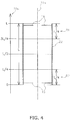
- FIG. 4 illustrates the height positions of the upper resonance-suppressing member 18 and the lower resonance-suppressing member 19 attached to the cylinder portion 22.
- FIG. 4 shows a longitudinal cross-sectional view of the cylinder portion 22 only.
- the cylinder portion 22 is schematically shown as a circular column.
- FIG. 4 shows a cylinder axis 22a that links the center of the upper surface and the center of the lower surface of the cylinder portion 22.
- the cylinder axis 22a is parallel to the vertical direction.
- the vertical dimension of the cylinder portion 22 is denoted below as L, the height position of the lower end of the cylinder portion 22 as zero, and the height position of the upper end of the cylinder portion 22 as L.
- a vertical coordinate axis 22b representing the height position is shown on the left side in FIG. 4 .
- the height position of the vertical center of the cylinder portion 22 is L/2.
- the height position of the upper resonance-suppressing member 18 is within a range of 3L/4 to L, and is preferably as close as possible to L.
- the height position of the lower resonance-suppressing member 19 is within a range of zero to L/4, and is preferably as close as possible to zero.
- the range of height positions from 3L/4 to L is shown as R1
- the range of height positions from zero to L/4 is shown as R2.
- the upper resonance-suppressing member 18 is installed in the range R1 from the height position (L) of the upper end of the cylinder portion 22 to the height position (3L/4), which is set apart by a distance of 25% of the dimension L of the cylinder portion 22 along the direction of the cylinder axis 22a from the upper end of the cylinder portion 22 to the lower end.
- the lower resonance-suppressing member 19 is installed in the range R2 from the height position (zero) of the lower end of the cylinder portion 22 to the height position (L/4), which is set apart by a distance of 25% of the dimension of the cylinder portion 22 along the direction of the cylinder axis 22a from the lower end of the cylinder portion 22 to the upper end.
- FIG. 5 is a longitudinal cross-sectional view of the compressor 101.
- the compressor 101 is a swing-type compressor.
- the compressor 101 is mainly configured from a compressor casing 111, a compression mechanism 115, a drive motor 116, a crankshaft 117, an intake tube 119, and a discharge tube 120.
- the compressor casing 111 is a vertically extending cylindrically shaped metal airtight container.
- the compressor casing 111 mainly accommodates the compression mechanism 115 and the drive motor 116.
- the compression mechanism 115 and the drive motor 116 are linked by the crankshaft 117.
- the crankshaft 117 is disposed in the internal space of the compressor casing 111 so as to extend vertically.
- Attached to the external peripheral surface of the compressor casing 111 is an accumulator support base 154 for securing the accumulator 11 to the compressor 101.
- the compression mechanism 115 is mainly configured from a piston 121, a bushing 122, a front head 123, a cylinder block 124, and a rear head 125.
- the compression mechanism 115 is immersed in refrigerator oil stored in a bottom part of the compressor casing 111.
- the refrigerator oil is lubricating oil supplied to sliding parts of the compression mechanism 115.
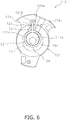
- FIG. 6 is a cross-sectional view at the height position indicated by arrows VI in FIG. 5 .
- the cylinder block 124 is a plate-shaped member in which a cylinder hole 124a, an intake hole 124b, a discharge channel 124c, a bushing accommodation hole 124d, and a blade accommodation hole 124e are formed.
- the cylinder hole 124a is a column-shaped hole through which the cylinder block 124 passes in a plate thickness direction.
- the intake hole 124b passes through from the external peripheral surface of the cylinder block 124 toward the cylinder hole 124a.
- the discharge channel 124c is a space formed by cutting out part of the internal peripheral surface of the cylinder hole 124a in the front head 123 side.
- the bushing accommodation hole 124d passes through the cylinder block 124 in the plate thickness direction.
- the bushing accommodation hole 124d when viewed along the plate thickness direction, is positioned between the intake hole 124b and the discharge channel 124c.
- the bushing accommodation hole 124d communicates with the cylinder hole 124a.
- the blade accommodation hole 124e passes through the cylinder block 124 in the plate thickness direction.
- the blade accommodation hole 124e communicates with the bushing accommodation hole 124d.
- the cylinder hole 124a accommodates an eccentric shaft part 117a of the crankshaft 117 and a rotor part 121a of the piston 121, as shown in FIG. 6 .
- the bushing accommodation hole 124d accommodates a blade part 121b of the piston 121 and the bushing 122.
- the blade accommodation hole 124e accommodates the blade part 121b of the piston 121.
- a cylinder chamber 115a is formed in the compression mechanism 115.
- the cylinder chamber 115a is a space enclosed in the front head 123, the cylinder block 124, and the rear head 125.
- the cylinder chamber 115a is partitioned by the piston 121 into an intake chamber communicating with the intake hole 124b and a discharge chamber communicating with the discharge channel 124c.
- the piston 121 is configured from the cylindrically shaped rotor part 121a, and the blade part 121b which protrudes outward in the radial direction of the rotor part 121a.
- the rotor part 121a is accommodated in the cylinder hole 124a of the cylinder block 124.
- the rotor part 121a is linked to the eccentric shaft part 117a of the crankshaft 117.
- the rotor part 121a When the crankshaft 117 rotates, the rotor part 121a performs an orbiting motion centered about the rotational axis of the crankshaft 117.
- the blade part 121b oscillates while being sandwiched in the bushing 122, and simultaneously performs a reciprocating motion along the longitudinal direction of the blade part 121b.
- the bushing 122 is a metal member in the shape of a pair of substantially circular columns. While sandwiching the blade part 121b of the piston 121, the bushing 122 can oscillate within the bushing accommodation hole 124d.
- the front head 123 is a member covering the discharge channel 124c side of the cylinder block 124.
- the front head 123 is joined to the internal peripheral surface of the compressor casing 111.
- the front head 123 has a bearing part 123a.
- the bearing part 123a supports the crankshaft 117.
- the front head 123 has an opening (not shown) for guiding gas refrigerant compressed in the cylinder chamber 115a to the space outside of the compression mechanism 115.
- the rear head 125 is a member covering the side of the cylinder block 124 opposite from the discharge channel 124c.
- the rear head 125 has a bearing part 125a.
- the bearing part 125a supports the crankshaft 117.
- the drive motor 116 is disposed above the compression mechanism 115, and is configured mainly from a stator 151 and a rotor 152.
- the stator 151 is an annular member fixed to the internal peripheral surface of the compressor casing 111.
- the rotor 152 is a cylindrical member installed on the inner side of the stator 151 so as to form a slight gap with the internal peripheral surface of the stator 151.
- the stator 151 has a plurality of teeth (not shown) that protrude inward from the internal peripheral surface of the stator. A copper wire is wound over the teeth to form a coil. Coil ends 153 are formed at the upper and lower end parts of the stator 151. In the external peripheral surface of the stator 151 are formed core cuts (not shown), which are grooves formed from the upper end of the stator 151 toward the lower end, and which are disposed at fixed intervals in a circumferential direction.
- the rotor 152 is linked to the crankshaft 117. When the crankshaft 117 rotates, the rotor 152 can rotate about the rotational axis of the crankshaft 117.
- the crankshaft 117 has the eccentric shaft part 117a, which is provided at the vertically lower end in as shown in FIG. 5 .
- the crankshaft 117 is linked to the drive motor 116 at the vertically upper end.
- the intake tube 119 is a tube attached passing through a side wall part of the compressor casing 111. One end of the intake tube 119 is fitted into the intake hole 124b of the cylinder block 124. The other end of the intake tube 119 is linked to the outlet tube 13 of the accumulator 11.
- the discharge tube 120 is a tube attached passing through an upper wall part of the compressor casing 111. One end of the discharge tube 120 is positioned above the drive motor 116 in the internal space of the compressor casing 111. The other end of the discharge tube 120 is connected to a pipe (not shown) of the refrigerant circuit.
- gas-liquid two-phase refrigerant is separated into gas refrigerant and liquid refrigerant.
- the gas-liquid two-phase refrigerant flows through the interior of the inlet tube 14 and into the internal space 12a.
- the gas-liquid two-phase refrigerant then passes through the filter 15, and impurities contaminating the refrigerant are removed.
- the gas-liquid two-phase refrigerant collides with the baffle 17. The liquid refrigerant contained in the gas-liquid two-phase refrigerant thereby adheres to the surface of the baffle 17.
- the liquid refrigerant adhering to the baffle 17 flows over the surface of the baffle 17 toward the outer edge, and falls through the internal space 12a to accumulate below the accumulator 11. Meanwhile, the gas refrigerant contained in the gas-liquid two-phase refrigerant flows from the internal space 12a into the outlet tube 13. The gas refrigerant flows through the interior of the outlet tube 13 and into the intake tube 119 of the compressor 101.
- the gas refrigerant separated in the accumulator 11 is drawn into the compressor 101.
- the gas refrigerant is periodically drawn into the cylinder chamber 115a in synchronization with the orbiting motion of the piston 121. Therefore, the step of gas refrigerant intake by the compressor 101 causes the pressure of the gas refrigerant to fluctuate in the internal space 12a of the accumulator 11. Specifically, the pressure in the internal space 12a decreases while the compressor 101 is drawing in gas refrigerant, and pressure in the internal space 12a increases while the compressor 101 is compressing gas refrigerant. In other words, pressure fluctuation in the gas refrigerant is a periodic change in the pressure in the internal space 12a.
- FIG. 7 is a longitudinal cross-sectional schematic view of an accumulator 211, serving as a comparative example, which does not have the resonance-suppressing members 18, 19.
- a casing 212 of the accumulator 211 is schematically shown to have a cylindrical shape.
- FIG. 7 shows a cylinder axis 212a that links the center of the upper surface and the center of the lower surface of this cylinder.
- the cylinder axis 212a is parallel to the vertical direction.
- the vertical dimension of the casing 212 is referred to as L.
- the pressure fluctuation in the gas refrigerant causes a standing wave in the vertical direction.
- the basic frequency of the standing wave is the frequency for a wavelength of 2L.
- the basic frequency of the standing wave though also dependent on the vertical dimension L of the casing 212, is 400 Hz to 900 Hz.
- a first wave W1 and a second wave W2, which occur when the standing wave amplitude is at a maximum, are shown respectively by solid lines and dashed lines.
- the arrows shown in FIG. 7 represent the distribution of the load of the gas refrigerant acting on the casing 212.
- the solid-line arrows represent the distribution of the pressure of gas refrigerant acting on the casing 212 when the first wave W1 is being generated.
- the dashed-line arrows represent the distribution of the pressure of gas refrigerant acting on the casing 212 when the second wave W2 is being generated.
- the first wave W1 and the second wave W2 are generated alternatingly in the internal space of the casing 212 at the basic frequency of the standing wave. In a horizontal cross section of the accumulator 211, the pressure distribution would be symmetric about the cylinder axis 212a.
- the first wave W1 and the second wave W2 have, from the upper end of the casing 212 toward the lower end, a first antinode P1, a node P2, and a second antinode P3.
- the first antinode P1 and the second antinode P3 are respectively in the height positions of the upper and lower ends of the casing 212, which are the height positions where the pressure fluctuation reaches a maximum.
- the node P2 is in the height position of the vertical center of the casing 212, which is the height position where the pressure fluctuation reaches zero.
- the standing wave described above resonates with the casing 212, whereby the casing 212 vibrates in the direction of the arrows shown in FIG. 7 .
- the casing 212 emits noise.
- the upper resonance-suppressing member 18 and the lower resonance-suppressing member 19 are attached at height positions near to, respectively, the upper end and lower end of the cylinder portion 22 of the casing 12.
- the height positions near to the upper end and lower end of the casing 212 are height positions where, respectively, the first antinode P1 and the second antinode P3 of the standing wave are present, and where pressure fluctuation reaches a maximum.
- the upper resonance-suppressing member 18 and the lower resonance-suppressing member 19 are attached at height positions near to the height positions where pressure fluctuation reaches a maximum in the internal space 12a.
- the upper resonance-suppressing member 18 and the lower resonance-suppressing member 19 have the effect of hindering pressure fluctuation. Therefore, by attaching the upper resonance-suppressing member 18 and the lower resonance-suppressing member 19 at height positions where pressure fluctuation reaches a maximum, i.e., height positions near to the upper end and lower end of the casing 12 within the internal space 12a of the accumulator 11, it is possible to reduce the maximum value of the pressure fluctuation amplitude and to eliminate resonance caused by pressure fluctuation. As a result, the vibration of the casing 12 of the accumulator 11 is minimized, and noise emitted from the accumulator 11 during operation is reduced.
- FIG. 8 is a schematic diagram of the first casing 91.
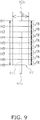
- FIG. 9 is a schematic diagram of the second casing 92.
- the rotational axes of the cylindrical shapes of the first casing 91 and second casing 92 run along the vertical direction.
- the vertical dimension L of the first casing 91 is 210.8 mm.
- the diameter D of the first casing 91 is 71.0 mm.
- the vertical dimension L of the second casing 92 is 129.0 mm.
- the diameter D of the second casing 92 is 47.8 mm.
- the first casing 91 has an outlet tube 91a and an inlet tube 91b.
- the second casing 92 has an outlet tube 92a and an inlet tube 92b.
- the outlet tubes 91a, 92a are equivalent to the outlet tube 13 of the embodiment.
- the inlet tubes 91b, 92b are equivalent to the inlet tube 14 of the embodiment.
- the outlet tubes 91a, 92a pass through lower end surfaces of the casings 91, 92, respectively. End parts of the outlet tubes 91a, 92a are positioned in the internal spaces of the casings 91, 92, respectively. End parts of the inlet tubes 91b, 92b are at the same height positions as upper end surfaces of the casings 91, 92, respectively.
- H1 to H9 are disposed at equal intervals in the vertical direction.
- H1 is height position level with the upper ends of the casings 91, 92.
- H2 is a height position at a distance of L/8 from the upper ends of the casings 91, 92 toward the lower ends.
- H3 is a height position at a distance of L/4 from the upper ends of the casings 91, 92 toward the lower ends.
- H4 is a height position at a distance of 3L/8 from the upper ends of the casings 91, 92 toward the lower ends.
- H5 is a height position in the middle between the upper and lower ends of the casings 91, 92.
- H6 is a height position at a distance of 3L/8 from the lower ends of the casings 91, 92 toward the upper ends.
- H7 is a height position at a distance of L/4 from the lower ends of the casings 91, 92 toward the upper ends.
- H8 is a height position at a distance of L/8 from the lower ends of the casings 91, 92 toward the upper ends.
- H9 is a height position level with the lower ends of the casings 91, 92.
- the height position of the end parts of the outlet tubes 91 a, 92a in the internal spaces of the casings 91, 92 is H3.
- Patterns of attachment positions for the imaginary resonance-suppressing members are configured from five patterns PT1 to PT5.
- a resonance-suppressing member is attached only at H5.
- resonance-suppressing members are attached at H4 and H6.
- resonance-suppressing members are attached at H3 and H7.
- resonance-suppressing members are attached at H2 and H8.
- resonance-suppressing members are attached at height positions where they will be near to H1 and H9 and will not make contact with the casings 91, 92.
- the gaps between the end surfaces of the casings 91, 92 and the resonance-suppressing members are 1 mm.
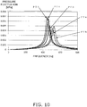
- FIGS. 10 and 11 show the analysis results for the first casing 91.
- FIGS. 12 and 13 show the analysis results for the second casing 92.
- FIGS. 10 and 12 show the analysis results of pressure fluctuation at the height position H1.
- FIGS. 11 and 13 show the analysis results of pressure fluctuation at the height position H9.
- the horizontal axes represent the frequencies (Hz) of the standing waves generated in the internal spaces of the casings 91, 92
- the vertical axes represent the sizes (MPa) of the standing waves generated in the internal spaces of the casings 91, 92.
- the accumulator 11 is provided with two resonance-suppressing members 18, 19.
- the upper resonance-suppressing member 18 and the lower resonance-suppressing member 19 are respectively attached to height positions near to the upper end and lower end of the cylinder portion 22 of the casing 12.
- the accumulator 11 is provided with only the upper resonance-suppressing member 18 or only the lower resonance-suppressing member 19.
- the upper resonance-suppressing member 18 or the lower resonance-suppressing member 19 hinders pressure fluctuation in the internal space 12a, and resonance caused by pressure fluctuation can be eliminated. As a result, noise emitted from the accumulator 11 during operation is reduced.
- FIGS. 14 and 15 are longitudinal cross-sectional views of the accumulator 11 according to the present modification.
- the accumulator 11 shown in FIG. 14 has a configuration in which the lower resonance-suppressing member 19 has been taken out of the accumulator 11 of the embodiment.
- the accumulator 11 shown in FIG. 15 has a configuration in which the upper resonance-suppressing member 18 has been taken out of the accumulator 11 of the embodiment.
- the accumulator 11 is provided with the annular resonance-suppressing members 18, 19 shown in FIGS. 2 and 3 .
- the external peripheral surfaces of the resonance-suppressing members 18, 19 are joined in their entirety to the internal peripheral surfaces of the cylinder portion 22 of the casing 12.
- FIG. 16 which is a cross-sectional view similar to FIG. 2 , shows an example of a resonance-suppressing member 118 of the present modification.
- the resonance-suppressing member 118 has an annular portion 118a, and two protruding parts 118b that protrude from the external peripheral surface of the annular portion 118a.
- the two protruding parts 118b are disposed so as to oppose each other about the center of the annular portion 118a.
- the two protruding parts 118b are joined to the internal peripheral surface of the cylinder portion 22 of the casing 12, whereby the resonance-suppressing member 118 is secured to the casing 12.
- gaps 118c are formed between the annular portion 118a and the cylinder portion 22. Liquid refrigerant colliding with the baffle 17 can fall through the gaps 118c.
- the resonance-suppressing member 118 is attached in at least one of the height positions where the resonance-suppressing members 18, 19 are installed in the embodiment.
- the resonance-suppressing member 118 may also have any desired number of protruding parts 118b.
- the compressor 101 connected with the accumulator 11 of the present embodiment is a single-cylinder compressor as shown in FIG. 5 .
- the compressor 101 may also be a dual-cylinder compressor.
- FIG. 17 is a longitudinal cross-sectional view of a compressor 301 to which an accumulator 311 in the present modification is connected.
- the compressor 301 is a dual-cylinder swing compressor.
- the compressor 301 is provided with a compression mechanism 315 and two intake tubes 319a, 319b.
- the compression mechanism 315 has two cylinder chambers 315a, 315b. In the compression mechanism 315, refrigerant drawn in from the upper intake tube 319a is compressed in the upper cylinder chamber 315a, and refrigerant drawn in from the lower intake tube 319b is compressed in the lower cylinder chamber 315b.
- the accumulator 311 is mainly provided with a casing 312, two outlet tubes 313a, 313b, an inlet tube 314, a filter 315, a holder 316, a baffle 317, and two resonance-suppressing members 318, 319.
- the inlet tube 314, the filter 315, the holder 316, and the baffle 317 are respectively identical to the inlet tube 14, the filter 15, the holder 16, and the baffle 17 of the embodiment.
- the two outlet tubes 313a, 313b are passed through and fixed to a bottom surface of the casing 312.
- the outlet tube 313a is linked to the inlet tube 319a of the compression mechanism 315.
- the outlet tube 313b is linked to the inlet tube 319b of the compression mechanism 315.
- the resonance-suppressing members 318, 319 which respectively have the same shapes as the resonance-suppressing members 18, 19 of the embodiment, are attached to the same height positions.
- the accumulator 311 may also be provided to only one of the two resonance-suppressing members 318, 319.
- the resonance-suppressing members 18, 19 of the accumulator 11 are annular members in which a single circular hole is formed in the middle, as shown in FIGS. 2 and 3 .
- the resonance-suppressing members 18, 19 may each have a hole in the shape of something other than a circle, or they may each have two or more holes. Next, modifications of the resonance-suppressing members 18, 19 are described with reference to FIGS. 18 to 22 .
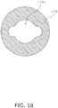
- FIG. 18 is a plan view of an upper resonance-suppressing member 418, which is one modification of the upper resonance-suppressing member 18.
- the upper resonance-suppressing member 418 can use the accumulator 11 connected to the single-cylinder compressor 101 shown in FIG. 5 , and the accumulator 311 connected to the dual-cylinder compressor 301 shown in FIG. 17 .
- the upper resonance-suppressing member 418 has a communication hole 418a in the middle.
- the communication hole 418a has the shape of something other than a circle.
- the configuration shown in FIG. 18 can also be applied to the lower resonance-suppressing member 19.
- FIG. 19 is a plan view of a lower resonance-suppressing member 419, which is one modification of the lower resonance-suppressing member 19.
- the lower resonance-suppressing member 419 can be used in the accumulator 11 connected to the single-cylinder compressor 101 shown in FIG. 5 .
- the lower resonance-suppressing member 419 has one tube passage hole 419b and six communication holes 419a.
- the tube passage hole 419b is formed in the middle of the lower resonance-suppressing member 419, and is a circular hole through which the outlet tube 13a passes.
- the diameter of the tube passage hole 419b is equal to the outside diameter of the outlet tube 13a.
- the communication holes 419a are circular holes formed around the periphery of the tube passage hole 419b, in six-fold symmetry about the center of the lower resonance-suppressing member 419.
- the shapes of the communication holes 419a are not limited to circles.
- the outlet tube 13a may be attached to the lower resonance-suppressing member 419 by brazing, etc. in the position where the outlet tube passes through the tube passage hole 419b. The attachment tolerance of the outlet tube 13a can be reduced by attaching the outlet tube 13a to the lower resonance-suppressing member 419.
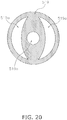
- FIG. 20 is a plan view of a lower resonance-suppressing member 519, which is one modification of the lower resonance-suppressing member 19.
- the lower resonance-suppressing member 519 can be used in the accumulator 11 connected to the single-cylinder compressor 101 shown in FIG. 5 .
- the lower resonance-suppressing member 519 has one tube passage hole 519b and two communication holes 519a.
- the tube passage hole 519b is formed in the middle of the lower resonance-suppressing member 519, and is a circular hole through which the outlet tube 13a passes.
- the diameter of the tube passage hole 519b is equal to the outside diameter of the outlet tube 13a.
- the communication holes 519a are fan-shaped holes formed around the periphery of the tube passage hole 519b, in two-fold symmetry about the center of the lower resonance-suppressing member 519.
- the shapes of the communication holes 519a are not limited to fans.
- the outlet tube 13a may be attached to the lower resonance-suppressing member 519 by brazing, etc. in the position where the outlet tube passes through the tube passage hole 519b. The attachment tolerance of the outlet tube 13a can be reduced by attaching the outlet tube 13a to the lower resonance-suppressing member 519.
- FIG. 21 is a plan view of a lower resonance-suppressing member 619, which is one modification of the resonance-suppressing member 319 of Modification C.
- the lower resonance-suppressing member 619 can be used in the accumulator 311 connected to the dual-cylinder compressor 301 shown in FIG. 17 .
- the lower resonance-suppressing member 619 has two tube passage holes 619b and two communication holes 619a.
- the two tube passage holes 619b are formed in the middle of the lower resonance-suppressing member 619, and are circular holes through which the outlet tubes 313a, 313b pass.
- the diameters of the tube passage holes 619b are equal to the outside diameters of the outlet tubes 313a, 313b.
- the communication holes 619a are arch-shaped holes formed around the periphery of the tube passage holes 619b, in two-fold symmetry about the center of the lower resonance-suppressing member 619.
- the shapes of the communication holes 619a are not limited to arch shapes.
- the outlet tubes 313a, 313b may be attached to the lower resonance-suppressing member 619 by brazing, etc. in the positions where the outlet tubes pass through the tube passage holes 619b.
- the attachment tolerance of the outlet tubes 313a, 313b can be reduced by attaching the outlet tubes 313a, 313b to the lower resonance-suppressing member 619.
- FIG. 22 is a plan view of a lower resonance-suppressing member 719, which is one modification of the lower resonance-suppressing member 319 of Modification C.
- the lower resonance-suppressing member 719 can be used in the accumulator 311 connected to the dual-cylinder compressor 301 shown in FIG. 17 .
- the lower resonance-suppressing member 719 has two tube passage holes 719b and two communication holes 719a.
- the two tube passage holes 719b are formed in the middle of the lower resonance-suppressing member 719, and are circular holes through which the outlet tubes 313a, 313b pass.
- the diameters of the tube passage holes 719b are equal to the outside diameters of the outlet tubes 313a, 313b.
- the communication holes 719a are fan-shaped holes formed around the periphery of the tube passage holes 719b, in two-fold symmetry about the center of the lower resonance-suppressing member 719.
- the shapes of the communication holes 719a are not limited to fan shapes.
- the outlet tubes 313a, 313b may be attached to the lower resonance-suppressing member 719 by brazing, etc. in the positions where the outlet tubes pass through the tube passage holes 719b.
- the attachment tolerance of the outlet tubes 313a, 313b can be reduced by attaching the outlet tubes 313a, 313b to the lower resonance-suppressing member 719.
- FIGS. 18 to 22 merely depict the present modification; the shapes, positions, and number of holes formed in the resonance-suppressing members shown in FIGS. 18 to 22 are not limited to those in the modification shown in FIGS. 18 to 22 .
- the present modification can also be applied to Modifications A and B.
- the resonance-suppressing members 18, 19 of the accumulator 11 according the present embodiment are thin sheets made of metal.
- the resonance-suppressing members 18, 19 are annular members attached respectively to the upper portion and lower portion of the casing 12, as shown in FIGS. 1 to 3 .
- the resonance-suppressing members 18, 19 may have surfaces that make contact with the internal peripheral surface of the casing 12, as is described below.
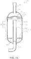
- FIG. 23 is a longitudinal cross-sectional view of the accumulator 11 according to the present modification.
- the accumulator 11 is provided with an upper resonance-suppressing member 818 and a lower resonance-suppressing member 819 attached to the upper portion and lower portion of the casing 12, respectively.
- FIG. 24 is an external perspective view of the upper resonance-suppressing member 818.
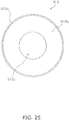
- FIG. 25 is a top view of the upper resonance-suppressing member 818.
- the upper resonance-suppressing member 818 is configured from a bottom surface part 818a and a side wall part 818b.
- the bottom surface part 818a is an annular member equivalent to the upper resonance-suppressing member 18 of the present embodiment.
- a circular hole 818c is formed in the middle of the bottom surface part 818a.
- the side wall part 818b is a cylindrical member formed as standing upright from the outer edge of the bottom surface part 818a.
- the bottom surface part 818a and the side wall part 818b may be mutually separate members or integrated members.
- the external peripheral surface of the side wall part 818b of the upper resonance-suppressing member 818 is brought into contact with the internal peripheral surface of the casing 12, and the side wall part 818b and the casing 12 are joined by brazing, welding, or another method, whereby the upper resonance-suppressing member 818 is secured to the casing 12.
- the above description pertaining to the upper resonance-suppressing member 818 can also be applied to the lower resonance-suppressing member 819.
- the bottom surface part 818a of the upper resonance-suppressing member 818 may have a hole in the shape of something other than a circle, and may have two or more holes.
- the bottom surface part 818a of the upper resonance-suppressing member 818 may have the hole shown in FIG. 18
- the bottom surface part of the lower resonance-suppressing member 819 may have the holes shown in FIGS. 19 to 22 .
- the compression mechanism 115 of the compressor 101 is a swing-type compression mechanism, but this compression mechanism may be, e.g., a rotary-type compression mechanism or a scroll-type compression mechanism.
- the compression mechanism 115 may also be provided with a two-stage compression mechanism.
- Patent Literature 1 Japanese Unexamined Utility Model Publication No. H3-83779
Landscapes
- Engineering & Computer Science (AREA)
- Chemical & Material Sciences (AREA)
- Analytical Chemistry (AREA)
- Power Engineering (AREA)
- Physics & Mathematics (AREA)
- Mechanical Engineering (AREA)
- Thermal Sciences (AREA)
- General Engineering & Computer Science (AREA)
- Compressor (AREA)
- Applications Or Details Of Rotary Compressors (AREA)
Abstract
Description
- The present invention relates to an accumulator that is installed near a compressor, and that separates a gas-liquid two-phase refrigerant into gas refrigerant and liquid refrigerant.
- Recently, air conditioners are being provided with accumulators installed near compressors. An accumulator separates a gas-liquid two-phase refrigerant drawn into the compressor into gas refrigerant and liquid refrigerant, and prevents the liquid refrigerant from flowing into the compressor.
- A compressor uses a compression mechanism installed therein to periodically drawn in gas refrigerant from the accumulator. The pressure of the gas refrigerant is thereby caused to fluctuate in an internal space in a casing of the accumulator. This pressure fluctuation causes resonance with the casing, and as a result, internal space resonance of 400 Hz to 900 Hz occurs in the internal space of the casing. The internal space resonance causes vibration in the accumulator. Therefore, various methods for eliminating internal space resonance have been employed. For example, in Patent Literature 1 (
Japanese Unexamined Utility Model Publication No. H3-83779 - The purpose of the present invention is to provide an accumulator with which resonance caused by pressure fluctuation in the internal space of the casing can be eliminated and noise can be reduced.
- An accumulator according to a first aspect of the present invention is a device for separating gas refrigerant and liquid refrigerant. The accumulator comprises a casing and a resonance-suppressing member. The resonance-suppressing member is installed in an internal space of the casing. The casing has a cylinder portion having a cylinder axis running along a vertical direction, an upper lid portion linked with an upper end of the cylinder portion, and a lower lid portion linked with a lower end of the cylinder portion.
- The resonance-suppressing member is installed at a height position that, in a case in which a standing wave of pressure having a first antinode, a node, and a second antinode from the upper lid portion toward the lower lid portion is generated in the internal space, is near to the height position of at least one of the first antinode and the second antinode.
- In the accumulator according to the first aspect, resonance-suppressing members are attached at height positions near to the upper end and lower end of the cylinder portion of the casing. A standing wave is generated in the internal space as a result of pressure fluctuation in the gas refrigerant. The standing wave has a first antinode, a node, and a second antinode from the upper lid portion toward the lower lid portion. The height positions near to the upper end and lower end of the cylinder portion are height positions where, respectively, the first antinode and second antinode of the standing wave are present, and where pressure fluctuation reaches a maximum. In other words, the resonance-suppressing members are attached at height positions near to the height positions where pressure fluctuation reaches a maximum. The resonance-suppressing members have the effect of hindering pressure fluctuation. Therefore, by attaching the resonance-suppressing members at height positions where pressure fluctuation reaches a maximum in the internal space; i.e., height positions near to the upper end and lower end of the cylinder portion, the maximum value of the pressure fluctuation amplitude can be reduced, and resonance caused by pressure fluctuation can be eliminated. As a result, casing vibration is minimized, and noise emitted from the accumulator during operation is reduced.
- An accumulator according to a second aspect of the present invention is the accumulator according to the first aspect. When the resonance-suppressing member is installed at a height position near to the height position of the first antinode, the resonance-suppressing member is installed in a range from the height position of the upper end of the cylinder portion to a height position set apart by a distance of 25% of the dimension of the cylinder portion along the direction of the cylinder axis from the upper end of the cylinder portion toward the lower end. When the resonance-suppressing member is installed at a height position near to the height position of the second antinode, the resonance-suppressing member is installed in a range from the height position of the lower end of the cylinder portion to a height position set apart by a distance of 25% of the dimension of the cylinder portion along the direction of the cylinder axis from the lower end of the cylinder portion toward the upper end.
- An accumulator according to a third aspect of the present invention is the accumulator according to the first aspect or second aspect, wherein the resonance-suppressing member is an annular member attached to an internal peripheral surface of the cylinder portion.
- With the accumulator according to the first through third aspects of the present invention, resonance caused by pressure fluctuation in the internal space of the casing can be eliminated and noise can be reduced.
-
-
FIG. 1 is a longitudinal cross-sectional view of an accumulator according to an embodiment of the present invention; -
FIG. 2 is a cross-sectional view in the height position indicated by the arrows II inFIG. 1 ; -
FIG. 3 is a cross-sectional view in the height position indicated by the arrows III inFIG. 1 ; -
FIG. 4 is a drawing for illustrating the height positions of the resonance-suppressing members; -
FIG. 5 is a longitudinal cross-sectional view of a compressor to which the accumulator is connected; -
FIG. 6 is a cross-sectional view at the height position indicated by the arrows VI inFIG. 5 ; -
FIG. 7 is a longitudinal cross-sectional schematic view of an accumulator, serving as a comparative example, that does not have resonance-suppressing members; -
FIG. 8 shows the shape and dimension of a first casing, and position of a resonance-suppressing member, according to an example; -
FIG 9 shows the shape and dimension of a second casing, and position of a resonance-suppressing member, according to an example; -
FIG. 10 shows analysis results for the first casing at a height position H1; -
FIG 11 shows analysis results for the first casing at a height position H9; -
FIG. 12 shows analysis results for the second casing at a height position H1; -
FIG. 13 shows analysis results for the second casing at a height position H9; -
FIG. 14 is a longitudinal cross-sectional view of an accumulator according to Modification A; -
FIG. 15 is a longitudinal cross-sectional view of an accumulator according to Modification A; -
FIG. 16 shows a resonance-suppressing member according to Modification B; -
FIG. 17 is a longitudinal cross-sectional view of a compressor to which an accumulator is connected, according to Modification C; -
FIG. 18 is an example of a plan view of an upper resonance-suppressing member according to Modification D; -
FIG. 19 is an example of a plan view of a lower resonance-suppressing member according to Modification D; -
FIG. 20 is an example of a plan view of a lower resonance-suppressing member according to Modification D; -
FIG. 21 is an example of a plan view of a lower resonance-suppressing member according to Modification D; -
FIG. 22 is an example of a plan view of a lower resonance-suppressing member according to Modification D; -
FIG. 23 is a longitudinal cross-sectional view of an accumulator according to Modification E; -
FIG. 24 is an external perspective view of an upper resonance-suppressing member according to Modification E; and -
FIG. 25 is a top view of the upper resonance-suppressing member according to Modification E. - An
accumulator 11 according to an embodiment of the present invention shall be described with reference to the drawings. -
FIG. 1 is a longitudinal cross-sectional view of theaccumulator 11. Theaccumulator 11 is provided to a refrigerant circuit of an air conditioning apparatus, etc. In the refrigerant circuit, theaccumulator 11 is connected to an intake side of acompressor 101, described hereinafter. - The
accumulator 11 separates the gas-liquid two-phase refrigerant drawn into thecompressor 101 into gas refrigerant and liquid refrigerant, and prevents the liquid refrigerant from flowing into thecompressor 101. The refrigerant is, e.g., R410A and R32. Theaccumulator 11 is mainly provided with acasing 12, anoutlet tube 13, aninlet tube 14, afilter 15, aholder 16, abaffle 17, and two resonance-suppressingmembers - The
casing 12 is a metal airtight container in which a dome-shapedupper lid portion 21, acylinder portion 22 in the shape of a cylinder, and a dome-shapedlower lid portion 23 are hermetically joined together. Thecasing 12 has aninternal space 12a that is a space enclosed by theupper lid portion 21, thecylinder portion 22, and thelower lid portion 23. Theupper lid portion 21 has aninlet hole 21a. Thelower lid portion 23 has anoutlet hole 23a. The gas-liquid two-phase refrigerant flows into theinternal space 12a from theinlet hole 21a. The gas refrigerant separated from the gas-liquid two-phase refrigerant flows out from theoutlet hole 23 a to be sent to thecompressor 101. - The
outlet tube 13 is attached to theoutlet hole 23a of thelower lid portion 23 of thecasing 12. Theoutlet tube 13 is configured from aninternal outlet tube 13a and anexternal outlet tube 13b. Theinternal outlet tube 13a, which is accommodated within theinternal space 12a of thecasing 12, extends vertically. Theexternal outlet tube 13b, which is hermetically joined to the internal periphery of theoutlet hole 23a, extends from theoutlet hole 23a toward the space outside of thecasing 12. Theexternal outlet tube 13b is connected to thecompressor 101. The lower end part of theinternal outlet tube 13a is joined to the end part of theexternal outlet tube 13b that is inside theinternal space 12a. The upper end part of theinternal outlet tube 13a is positioned above the height position of the vertical center of thecasing 12. - The
inlet tube 14 is attached to theinlet hole 21 a in theupper lid portion 21 of thecasing 12. Theinlet tube 14, which is hermetically joined to the internal periphery of theinlet hole 21a, extends from theinlet hole 21a toward the space outside of thecasing 12. Theinlet tube 14 is connected to a pipe (not shown) of the refrigerant circuit in the space outside of thecasing 12. - The
filter 15 is accommodated within theinternal space 12a of thecasing 12. Thefilter 15 is a member for filtering the refrigerant flowing in from theinlet hole 21a in theupper lid portion 21 of thecasing 12, and removing impurities that have contaminated the refrigerant. Thefilter 15 is, e.g., a metal mesh. - The
holder 16 is accommodated within theinternal space 12a of thecasing 12. Theholder 16 is a metal member for securing thefilter 15 to a predetermined position in theinternal space 12a. Theholder 16 is attached to an inner-side surface of theupper lid portion 21. - The
baffle 17 is accommodated within theinternal space 12a of thecasing 12. Thebaffle 17 is a thin metal sheet for preventing the liquid component of the refrigerant flowing in from theinlet hole 21 a in theupper lid portion 21 of thecasing 12 from flowing directly into theoutlet tube 13. The middle portion of thebaffle 17 is shaped to protrude vertically upward. Thebaffle 17 is attached to the inner-side surface of theupper lid portion 21 below thefilter 15. - The resonance-suppressing
members internal space 12a of thecasing 12 and attached to an internal peripheral surface of thecylinder portion 22 of thecasing 12.FIG. 2 is a cross-sectional view in the height position indicated by arrows II inFIG. 1 .FIG. 3 is a cross-sectional view in the height position indicated by arrows III inFIG. 1 . The resonance-suppressingmembers casing 12, as shown inFIGS. 2 and3 . The entirety of the external peripheral surfaces of the resonance-suppressingmembers cylinder portion 22, whereby the resonance-suppressingmembers casing 12. Hereinafter, if necessary, the top resonance-suppressingmember 18 shown inFIG. 2 is referred to as the upper resonance-suppressingmember 18, and the bottom resonance-suppressingmember 19 shown inFIG. 3 is referred to as the lower resonance-suppressingmember 19. - The upper resonance-suppressing
member 18 is attached to a height position near the portion where theupper lid portion 21 and thecylinder portion 22 are joined. The lower resonance-suppressingmember 19 is attached to a height position near the portion where thecylinder portion 22 and thelower lid portion 23 are joined. The height positions of the upper resonance-suppressingmember 18 and the lower resonance-suppressingmember 19 shall now be described.FIG. 4 illustrates the height positions of the upper resonance-suppressingmember 18 and the lower resonance-suppressingmember 19 attached to thecylinder portion 22.FIG. 4 shows a longitudinal cross-sectional view of thecylinder portion 22 only. InFIG. 4 , thecylinder portion 22 is schematically shown as a circular column.FIG. 4 shows acylinder axis 22a that links the center of the upper surface and the center of the lower surface of thecylinder portion 22. Thecylinder axis 22a is parallel to the vertical direction. - The vertical dimension of the
cylinder portion 22 is denoted below as L, the height position of the lower end of thecylinder portion 22 as zero, and the height position of the upper end of thecylinder portion 22 as L. A vertical coordinateaxis 22b representing the height position is shown on the left side inFIG. 4 . For example, the height position of the vertical center of thecylinder portion 22 is L/2. The height position of the upper resonance-suppressingmember 18 is within a range of 3L/4 to L, and is preferably as close as possible to L. The height position of the lower resonance-suppressingmember 19 is within a range of zero to L/4, and is preferably as close as possible to zero. InFIG. 4 , the range of height positions from 3L/4 to L is shown as R1, and the range of height positions from zero to L/4 is shown as R2. - In other words, the upper resonance-suppressing
member 18 is installed in the range R1 from the height position (L) of the upper end of thecylinder portion 22 to the height position (3L/4), which is set apart by a distance of 25% of the dimension L of thecylinder portion 22 along the direction of thecylinder axis 22a from the upper end of thecylinder portion 22 to the lower end. The lower resonance-suppressingmember 19 is installed in the range R2 from the height position (zero) of the lower end of thecylinder portion 22 to the height position (L/4), which is set apart by a distance of 25% of the dimension of thecylinder portion 22 along the direction of thecylinder axis 22a from the lower end of thecylinder portion 22 to the upper end. - Next, the configuration of the
compressor 101 connected to theaccumulator 11 shall be described.FIG. 5 is a longitudinal cross-sectional view of thecompressor 101. Thecompressor 101 is a swing-type compressor. Thecompressor 101 is mainly configured from acompressor casing 111, acompression mechanism 115, adrive motor 116, acrankshaft 117, anintake tube 119, and adischarge tube 120. - The
compressor casing 111 is a vertically extending cylindrically shaped metal airtight container. Thecompressor casing 111 mainly accommodates thecompression mechanism 115 and thedrive motor 116. Thecompression mechanism 115 and thedrive motor 116 are linked by thecrankshaft 117. Thecrankshaft 117 is disposed in the internal space of thecompressor casing 111 so as to extend vertically. Attached to the external peripheral surface of thecompressor casing 111 is anaccumulator support base 154 for securing theaccumulator 11 to thecompressor 101. - The
compression mechanism 115 is mainly configured from apiston 121, abushing 122, afront head 123, acylinder block 124, and arear head 125. Thecompression mechanism 115 is immersed in refrigerator oil stored in a bottom part of thecompressor casing 111. The refrigerator oil is lubricating oil supplied to sliding parts of thecompression mechanism 115.FIG. 6 is a cross-sectional view at the height position indicated by arrows VI inFIG. 5 . - The
cylinder block 124 is a plate-shaped member in which acylinder hole 124a, anintake hole 124b, adischarge channel 124c, abushing accommodation hole 124d, and ablade accommodation hole 124e are formed. Thecylinder hole 124a is a column-shaped hole through which thecylinder block 124 passes in a plate thickness direction. Theintake hole 124b passes through from the external peripheral surface of thecylinder block 124 toward thecylinder hole 124a. Thedischarge channel 124c is a space formed by cutting out part of the internal peripheral surface of thecylinder hole 124a in thefront head 123 side. Thebushing accommodation hole 124d passes through thecylinder block 124 in the plate thickness direction. Thebushing accommodation hole 124d, when viewed along the plate thickness direction, is positioned between theintake hole 124b and thedischarge channel 124c. Thebushing accommodation hole 124d communicates with thecylinder hole 124a. Theblade accommodation hole 124e passes through thecylinder block 124 in the plate thickness direction. Theblade accommodation hole 124e communicates with thebushing accommodation hole 124d. - The
cylinder hole 124a accommodates aneccentric shaft part 117a of thecrankshaft 117 and arotor part 121a of thepiston 121, as shown inFIG. 6 . Thebushing accommodation hole 124d accommodates ablade part 121b of thepiston 121 and thebushing 122. Theblade accommodation hole 124e accommodates theblade part 121b of thepiston 121. - A
cylinder chamber 115a is formed in thecompression mechanism 115. Thecylinder chamber 115a is a space enclosed in thefront head 123, thecylinder block 124, and therear head 125. Thecylinder chamber 115a is partitioned by thepiston 121 into an intake chamber communicating with theintake hole 124b and a discharge chamber communicating with thedischarge channel 124c. - The
piston 121 is configured from the cylindrically shapedrotor part 121a, and theblade part 121b which protrudes outward in the radial direction of therotor part 121a. Therotor part 121a is accommodated in thecylinder hole 124a of thecylinder block 124. Therotor part 121a is linked to theeccentric shaft part 117a of thecrankshaft 117. When thecrankshaft 117 rotates, therotor part 121a performs an orbiting motion centered about the rotational axis of thecrankshaft 117. Theblade part 121b oscillates while being sandwiched in thebushing 122, and simultaneously performs a reciprocating motion along the longitudinal direction of theblade part 121b. - The
bushing 122 is a metal member in the shape of a pair of substantially circular columns. While sandwiching theblade part 121b of thepiston 121, thebushing 122 can oscillate within thebushing accommodation hole 124d. - The
front head 123 is a member covering thedischarge channel 124c side of thecylinder block 124. Thefront head 123 is joined to the internal peripheral surface of thecompressor casing 111. Thefront head 123 has abearing part 123a. The bearingpart 123a supports thecrankshaft 117. Thefront head 123 has an opening (not shown) for guiding gas refrigerant compressed in thecylinder chamber 115a to the space outside of thecompression mechanism 115. - The
rear head 125 is a member covering the side of thecylinder block 124 opposite from thedischarge channel 124c. Therear head 125 has abearing part 125a. The bearingpart 125a supports thecrankshaft 117. - The
drive motor 116 is disposed above thecompression mechanism 115, and is configured mainly from astator 151 and arotor 152. Thestator 151 is an annular member fixed to the internal peripheral surface of thecompressor casing 111. Therotor 152 is a cylindrical member installed on the inner side of thestator 151 so as to form a slight gap with the internal peripheral surface of thestator 151. - The
stator 151 has a plurality of teeth (not shown) that protrude inward from the internal peripheral surface of the stator. A copper wire is wound over the teeth to form a coil. Coil ends 153 are formed at the upper and lower end parts of thestator 151. In the external peripheral surface of thestator 151 are formed core cuts (not shown), which are grooves formed from the upper end of thestator 151 toward the lower end, and which are disposed at fixed intervals in a circumferential direction. - The
rotor 152 is linked to thecrankshaft 117. When thecrankshaft 117 rotates, therotor 152 can rotate about the rotational axis of thecrankshaft 117. - The
crankshaft 117 has theeccentric shaft part 117a, which is provided at the vertically lower end in as shown inFIG. 5 . Thecrankshaft 117 is linked to thedrive motor 116 at the vertically upper end. - The
intake tube 119 is a tube attached passing through a side wall part of thecompressor casing 111. One end of theintake tube 119 is fitted into theintake hole 124b of thecylinder block 124. The other end of theintake tube 119 is linked to theoutlet tube 13 of theaccumulator 11. - The
discharge tube 120 is a tube attached passing through an upper wall part of thecompressor casing 111. One end of thedischarge tube 120 is positioned above thedrive motor 116 in the internal space of thecompressor casing 111. The other end of thedischarge tube 120 is connected to a pipe (not shown) of the refrigerant circuit. - In the
internal space 12a of theaccumulator 11, gas-liquid two-phase refrigerant is separated into gas refrigerant and liquid refrigerant. First, the gas-liquid two-phase refrigerant flows through the interior of theinlet tube 14 and into theinternal space 12a. Next, the gas-liquid two-phase refrigerant then passes through thefilter 15, and impurities contaminating the refrigerant are removed. Next, the gas-liquid two-phase refrigerant collides with thebaffle 17. The liquid refrigerant contained in the gas-liquid two-phase refrigerant thereby adheres to the surface of thebaffle 17. The liquid refrigerant adhering to thebaffle 17 flows over the surface of thebaffle 17 toward the outer edge, and falls through theinternal space 12a to accumulate below theaccumulator 11. Meanwhile, the gas refrigerant contained in the gas-liquid two-phase refrigerant flows from theinternal space 12a into theoutlet tube 13. The gas refrigerant flows through the interior of theoutlet tube 13 and into theintake tube 119 of thecompressor 101. - The gas refrigerant separated in the
accumulator 11 is drawn into thecompressor 101. In thecompression mechanism 115 of thecompressor 101, the gas refrigerant is periodically drawn into thecylinder chamber 115a in synchronization with the orbiting motion of thepiston 121. Therefore, the step of gas refrigerant intake by thecompressor 101 causes the pressure of the gas refrigerant to fluctuate in theinternal space 12a of theaccumulator 11. Specifically, the pressure in theinternal space 12a decreases while thecompressor 101 is drawing in gas refrigerant, and pressure in theinternal space 12a increases while thecompressor 101 is compressing gas refrigerant. In other words, pressure fluctuation in the gas refrigerant is a periodic change in the pressure in theinternal space 12a. -
FIG. 7 is a longitudinal cross-sectional schematic view of anaccumulator 211, serving as a comparative example, which does not have the resonance-suppressingmembers FIG. 7 , acasing 212 of theaccumulator 211 is schematically shown to have a cylindrical shape.FIG. 7 shows acylinder axis 212a that links the center of the upper surface and the center of the lower surface of this cylinder. Thecylinder axis 212a is parallel to the vertical direction. Hereinafter, the vertical dimension of thecasing 212 is referred to as L. - In the internal space of the
casing 212 of theaccumulator 211, the pressure fluctuation in the gas refrigerant causes a standing wave in the vertical direction. The basic frequency of the standing wave is the frequency for a wavelength of 2L. The basic frequency of the standing wave, though also dependent on the vertical dimension L of thecasing 212, is 400 Hz to 900 Hz. InFIG. 7 , a first wave W1 and a second wave W2, which occur when the standing wave amplitude is at a maximum, are shown respectively by solid lines and dashed lines. The arrows shown inFIG. 7 represent the distribution of the load of the gas refrigerant acting on thecasing 212. The solid-line arrows represent the distribution of the pressure of gas refrigerant acting on thecasing 212 when the first wave W1 is being generated. The dashed-line arrows represent the distribution of the pressure of gas refrigerant acting on thecasing 212 when the second wave W2 is being generated. The first wave W1 and the second wave W2 are generated alternatingly in the internal space of thecasing 212 at the basic frequency of the standing wave. In a horizontal cross section of theaccumulator 211, the pressure distribution would be symmetric about thecylinder axis 212a. - The first wave W1 and the second wave W2 have, from the upper end of the
casing 212 toward the lower end, a first antinode P1, a node P2, and a second antinode P3. The first antinode P1 and the second antinode P3 are respectively in the height positions of the upper and lower ends of thecasing 212, which are the height positions where the pressure fluctuation reaches a maximum. The node P2 is in the height position of the vertical center of thecasing 212, which is the height position where the pressure fluctuation reaches zero. - In the
accumulator 211 serving as a comparative example, the standing wave described above resonates with thecasing 212, whereby thecasing 212 vibrates in the direction of the arrows shown inFIG. 7 . As a result, thecasing 212 emits noise. - On the other hand, in the
accumulator 11 according to the present embodiment, the upper resonance-suppressingmember 18 and the lower resonance-suppressingmember 19 are attached at height positions near to, respectively, the upper end and lower end of thecylinder portion 22 of thecasing 12. In theaccumulator 211 serving as a comparative example, the height positions near to the upper end and lower end of thecasing 212 are height positions where, respectively, the first antinode P1 and the second antinode P3 of the standing wave are present, and where pressure fluctuation reaches a maximum. In other words, in the present embodiment, the upper resonance-suppressingmember 18 and the lower resonance-suppressingmember 19 are attached at height positions near to the height positions where pressure fluctuation reaches a maximum in theinternal space 12a. - The upper resonance-suppressing
member 18 and the lower resonance-suppressingmember 19 have the effect of hindering pressure fluctuation. Therefore, by attaching the upper resonance-suppressingmember 18 and the lower resonance-suppressingmember 19 at height positions where pressure fluctuation reaches a maximum, i.e., height positions near to the upper end and lower end of thecasing 12 within theinternal space 12a of theaccumulator 11, it is possible to reduce the maximum value of the pressure fluctuation amplitude and to eliminate resonance caused by pressure fluctuation. As a result, the vibration of thecasing 12 of theaccumulator 11 is minimized, and noise emitted from theaccumulator 11 during operation is reduced. - There follows a description of the results of using a simulation to analyze the effect by which the upper resonance-suppressing
member 18 and the lower resonance-suppressingmember 19 hinder pressure fluctuation. The simulation analysis results were used to examine the range of height positions for the upper resonance-suppressingmember 18 and the lower resonance-suppressingmember 19 at which the effect of hindering pressure fluctuation occurred. Specifically, calculations were made of pressure fluctuation in internal spaces of an imaginaryfirst casing 91 andsecond casing 92, which had cylindrical shapes. Thefirst casing 91 was envisioned as a casing of an accumulator attached to a large swing-type compressor. Thesecond casing 92 was envisioned as a casing of an accumulator attached to a small swing-type compressor. Imaginary resonance-suppressing members, equivalent to the upper resonance-suppressingmember 18 and the lower resonance-suppressingmember 19, were attached in the internal spaces of thefirst casing 91 and thesecond casing 92, respectively. -
FIG. 8 is a schematic diagram of thefirst casing 91.FIG. 9 is a schematic diagram of thesecond casing 92. The rotational axes of the cylindrical shapes of thefirst casing 91 andsecond casing 92 run along the vertical direction. The vertical dimension L of thefirst casing 91 is 210.8 mm. The diameter D of thefirst casing 91 is 71.0 mm. The vertical dimension L of thesecond casing 92 is 129.0 mm. The diameter D of thesecond casing 92 is 47.8 mm. - The
first casing 91 has anoutlet tube 91a and aninlet tube 91b. Thesecond casing 92 has anoutlet tube 92a and aninlet tube 92b. Theoutlet tubes outlet tube 13 of the embodiment. Theinlet tubes inlet tube 14 of the embodiment. Theoutlet tubes casings outlet tubes casings inlet tubes casings - Height positions H1 to H9 in nine locations are defined as shown in
FIGS. 8 and9 . H1 to H9 are disposed at equal intervals in the vertical direction. H1 is height position level with the upper ends of thecasings casings casings casings casings casings casings casings casings outlet tubes casings - Patterns of attachment positions for the imaginary resonance-suppressing members are configured from five patterns PT1 to PT5. With pattern PT1, a resonance-suppressing member is attached only at H5. With pattern PT2, resonance-suppressing members are attached at H4 and H6. With pattern PT3, resonance-suppressing members are attached at H3 and H7. With pattern PT4, resonance-suppressing members are attached at H2 and H8. With pattern PT5, resonance-suppressing members are attached at height positions where they will be near to H1 and H9 and will not make contact with the
casings casings -
FIGS. 10 and11 show the analysis results for thefirst casing 91.FIGS. 12 and13 show the analysis results for thesecond casing 92.FIGS. 10 and12 show the analysis results of pressure fluctuation at the height position H1.FIGS. 11 and13 show the analysis results of pressure fluctuation at the height position H9. InFIGS. 10 to 13 , the horizontal axes represent the frequencies (Hz) of the standing waves generated in the internal spaces of thecasings casings - At frequencies of 400 Hz to 900 Hz, the maximum values of pressure fluctuation in patterns PT3 to PT5 are lower than the maximum values of pressure fluctuation in patterns PT1 and PT2, as shown in
FIGS. 10 to 13 . In other words, with patterns PT3 to PT5, the effect of pressure fluctuation being hindered by the resonance-suppressing members was confirmed. It was also confirmed that this effect is independent of the height and diameter of thecasings casings casings - The
accumulator 11 according to the present embodiment is provided with two resonance-suppressingmembers member 18 and the lower resonance-suppressingmember 19 are respectively attached to height positions near to the upper end and lower end of thecylinder portion 22 of thecasing 12. - However, another option is for the
accumulator 11 to be provided with only the upper resonance-suppressingmember 18 or only the lower resonance-suppressingmember 19. In this case as well, the upper resonance-suppressingmember 18 or the lower resonance-suppressingmember 19 hinders pressure fluctuation in theinternal space 12a, and resonance caused by pressure fluctuation can be eliminated. As a result, noise emitted from theaccumulator 11 during operation is reduced. -
FIGS. 14 and15 are longitudinal cross-sectional views of theaccumulator 11 according to the present modification. Theaccumulator 11 shown inFIG. 14 has a configuration in which the lower resonance-suppressingmember 19 has been taken out of theaccumulator 11 of the embodiment. Theaccumulator 11 shown inFIG. 15 has a configuration in which the upper resonance-suppressingmember 18 has been taken out of theaccumulator 11 of the embodiment. - The
accumulator 11 according to the present embodiment is provided with the annular resonance-suppressingmembers FIGS. 2 and3 . The external peripheral surfaces of the resonance-suppressingmembers cylinder portion 22 of thecasing 12. - However, as long as the resonance-suppressing
members FIG. 16 , which is a cross-sectional view similar toFIG. 2 , shows an example of a resonance-suppressingmember 118 of the present modification. The resonance-suppressingmember 118 has anannular portion 118a, and two protrudingparts 118b that protrude from the external peripheral surface of theannular portion 118a. The two protrudingparts 118b are disposed so as to oppose each other about the center of theannular portion 118a. The two protrudingparts 118b are joined to the internal peripheral surface of thecylinder portion 22 of thecasing 12, whereby the resonance-suppressingmember 118 is secured to thecasing 12. In this case,gaps 118c are formed between theannular portion 118a and thecylinder portion 22. Liquid refrigerant colliding with thebaffle 17 can fall through thegaps 118c. - In the present modification, the resonance-suppressing
member 118 is attached in at least one of the height positions where the resonance-suppressingmembers member 118 may also have any desired number of protrudingparts 118b. - The
compressor 101 connected with theaccumulator 11 of the present embodiment is a single-cylinder compressor as shown inFIG. 5 . However, thecompressor 101 may also be a dual-cylinder compressor. -
FIG. 17 is a longitudinal cross-sectional view of acompressor 301 to which anaccumulator 311 in the present modification is connected. InFIG. 17 , configurative elements identical to those inFIG. 5 are denoted by the same reference symbols. Thecompressor 301 is a dual-cylinder swing compressor. Thecompressor 301 is provided with acompression mechanism 315 and twointake tubes compression mechanism 315 has twocylinder chambers 315a, 315b. In thecompression mechanism 315, refrigerant drawn in from theupper intake tube 319a is compressed in theupper cylinder chamber 315a, and refrigerant drawn in from thelower intake tube 319b is compressed in the lower cylinder chamber 315b. - The
accumulator 311 is mainly provided with acasing 312, twooutlet tubes inlet tube 314, afilter 315, aholder 316, abaffle 317, and two resonance-suppressingmembers inlet tube 314, thefilter 315, theholder 316, and thebaffle 317 are respectively identical to theinlet tube 14, thefilter 15, theholder 16, and thebaffle 17 of the embodiment. The twooutlet tubes casing 312. Theoutlet tube 313a is linked to theinlet tube 319a of thecompression mechanism 315. Theoutlet tube 313b is linked to theinlet tube 319b of thecompression mechanism 315. The resonance-suppressingmembers members - In the present modification, the
accumulator 311 may also be provided to only one of the two resonance-suppressingmembers - The resonance-suppressing
members accumulator 11 according to the present embodiment are annular members in which a single circular hole is formed in the middle, as shown inFIGS. 2 and3 . However, the resonance-suppressingmembers members FIGS. 18 to 22 . -
FIG. 18 is a plan view of an upper resonance-suppressingmember 418, which is one modification of the upper resonance-suppressingmember 18. The upper resonance-suppressingmember 418 can use theaccumulator 11 connected to the single-cylinder compressor 101 shown inFIG. 5 , and theaccumulator 311 connected to the dual-cylinder compressor 301 shown inFIG. 17 . The upper resonance-suppressingmember 418 has acommunication hole 418a in the middle. Thecommunication hole 418a has the shape of something other than a circle. The configuration shown inFIG. 18 can also be applied to the lower resonance-suppressingmember 19. -
FIG. 19 is a plan view of a lower resonance-suppressingmember 419, which is one modification of the lower resonance-suppressingmember 19. The lower resonance-suppressingmember 419 can be used in theaccumulator 11 connected to the single-cylinder compressor 101 shown inFIG. 5 . The lower resonance-suppressingmember 419 has onetube passage hole 419b and sixcommunication holes 419a. Thetube passage hole 419b is formed in the middle of the lower resonance-suppressingmember 419, and is a circular hole through which theoutlet tube 13a passes. The diameter of thetube passage hole 419b is equal to the outside diameter of theoutlet tube 13a. Thecommunication holes 419a are circular holes formed around the periphery of thetube passage hole 419b, in six-fold symmetry about the center of the lower resonance-suppressingmember 419. The shapes of thecommunication holes 419a are not limited to circles. Theoutlet tube 13a may be attached to the lower resonance-suppressingmember 419 by brazing, etc. in the position where the outlet tube passes through thetube passage hole 419b. The attachment tolerance of theoutlet tube 13a can be reduced by attaching theoutlet tube 13a to the lower resonance-suppressingmember 419. -
FIG. 20 is a plan view of a lower resonance-suppressingmember 519, which is one modification of the lower resonance-suppressingmember 19. The lower resonance-suppressingmember 519 can be used in theaccumulator 11 connected to the single-cylinder compressor 101 shown inFIG. 5 . The lower resonance-suppressingmember 519 has onetube passage hole 519b and twocommunication holes 519a. Thetube passage hole 519b is formed in the middle of the lower resonance-suppressingmember 519, and is a circular hole through which theoutlet tube 13a passes. The diameter of thetube passage hole 519b is equal to the outside diameter of theoutlet tube 13a. Thecommunication holes 519a are fan-shaped holes formed around the periphery of thetube passage hole 519b, in two-fold symmetry about the center of the lower resonance-suppressingmember 519. The shapes of thecommunication holes 519a are not limited to fans. Theoutlet tube 13a may be attached to the lower resonance-suppressingmember 519 by brazing, etc. in the position where the outlet tube passes through thetube passage hole 519b. The attachment tolerance of theoutlet tube 13a can be reduced by attaching theoutlet tube 13a to the lower resonance-suppressingmember 519. -
FIG. 21 is a plan view of a lower resonance-suppressingmember 619, which is one modification of the resonance-suppressingmember 319 of Modification C. The lower resonance-suppressingmember 619 can be used in theaccumulator 311 connected to the dual-cylinder compressor 301 shown inFIG. 17 . The lower resonance-suppressingmember 619 has two tube passage holes 619b and twocommunication holes 619a. The two tube passage holes 619b are formed in the middle of the lower resonance-suppressingmember 619, and are circular holes through which theoutlet tubes outlet tubes communication holes 619a are arch-shaped holes formed around the periphery of the tube passage holes 619b, in two-fold symmetry about the center of the lower resonance-suppressingmember 619. The shapes of thecommunication holes 619a are not limited to arch shapes. Theoutlet tubes member 619 by brazing, etc. in the positions where the outlet tubes pass through the tube passage holes 619b. The attachment tolerance of theoutlet tubes outlet tubes member 619. -
FIG. 22 is a plan view of a lower resonance-suppressingmember 719, which is one modification of the lower resonance-suppressingmember 319 of Modification C. The lower resonance-suppressingmember 719 can be used in theaccumulator 311 connected to the dual-cylinder compressor 301 shown inFIG. 17 . The lower resonance-suppressingmember 719 has two tube passage holes 719b and twocommunication holes 719a. The two tube passage holes 719b are formed in the middle of the lower resonance-suppressingmember 719, and are circular holes through which theoutlet tubes outlet tubes communication holes 719a are fan-shaped holes formed around the periphery of the tube passage holes 719b, in two-fold symmetry about the center of the lower resonance-suppressingmember 719. The shapes of thecommunication holes 719a are not limited to fan shapes. Theoutlet tubes member 719 by brazing, etc. in the positions where the outlet tubes pass through the tube passage holes 719b. The attachment tolerance of theoutlet tubes outlet tubes member 719. -
FIGS. 18 to 22 merely depict the present modification; the shapes, positions, and number of holes formed in the resonance-suppressing members shown inFIGS. 18 to 22 are not limited to those in the modification shown inFIGS. 18 to 22 . The present modification can also be applied to Modifications A and B. - The resonance-suppressing
members accumulator 11 according the present embodiment are thin sheets made of metal. The resonance-suppressingmembers casing 12, as shown inFIGS. 1 to 3 . However, the resonance-suppressingmembers casing 12, as is described below. -
FIG. 23 is a longitudinal cross-sectional view of theaccumulator 11 according to the present modification. Theaccumulator 11 is provided with an upper resonance-suppressingmember 818 and a lower resonance-suppressingmember 819 attached to the upper portion and lower portion of thecasing 12, respectively.FIG. 24 is an external perspective view of the upper resonance-suppressingmember 818.FIG. 25 is a top view of the upper resonance-suppressingmember 818. The upper resonance-suppressingmember 818 is configured from abottom surface part 818a and aside wall part 818b. Thebottom surface part 818a is an annular member equivalent to the upper resonance-suppressingmember 18 of the present embodiment. Acircular hole 818c is formed in the middle of thebottom surface part 818a. Theside wall part 818b is a cylindrical member formed as standing upright from the outer edge of thebottom surface part 818a. Thebottom surface part 818a and theside wall part 818b may be mutually separate members or integrated members. The external peripheral surface of theside wall part 818b of the upper resonance-suppressingmember 818 is brought into contact with the internal peripheral surface of thecasing 12, and theside wall part 818b and thecasing 12 are joined by brazing, welding, or another method, whereby the upper resonance-suppressingmember 818 is secured to thecasing 12. The above description pertaining to the upper resonance-suppressingmember 818 can also be applied to the lower resonance-suppressingmember 819. - The present modification can be applied to Modifications A through D as well. For example, the
bottom surface part 818a of the upper resonance-suppressingmember 818 may have a hole in the shape of something other than a circle, and may have two or more holes. Specifically, thebottom surface part 818a of the upper resonance-suppressingmember 818 may have the hole shown inFIG. 18 , and the bottom surface part of the lower resonance-suppressingmember 819 may have the holes shown inFIGS. 19 to 22 . - In the present modification, the
compression mechanism 115 of thecompressor 101 is a swing-type compression mechanism, but this compression mechanism may be, e.g., a rotary-type compression mechanism or a scroll-type compression mechanism. Thecompression mechanism 115 may also be provided with a two-stage compression mechanism. - With the accumulator according to the present invention, resonance caused by pressure fluctuation in the internal space of the casing can be eliminated and noise can be reduced.
-
- 11
- Accumulator
- 12
- Casing
- 12a
- Internal space
- 18
- Resonance-suppressing member
- 19
- Resonance-suppressing member
- 21
- Upper lid portion
- 22
- Cylinder portion
- 22a
- Cylinder axis
- 23
- Lower lid portion
- [Patent Literature 1]
Japanese Unexamined Utility Model Publication No. H3-83779
Claims (3)
- An accumulator (11) for separating gas refrigerant and liquid refrigerant, the accumulator comprising:a casing (12); anda resonance-suppressing member (18, 19) installed in an internal space (12a) of the casing;the casing having:a cylinder portion (22) having a cylinder axis (22a) running along a vertical direction;an upper lid portion (21) linked with an upper end of the cylinder portion; anda lower lid portion (23) linked with a lower end of the cylinder portion;and the resonance-suppressing member being installed at a height position that, in a case in which a standing wave of pressure having a first antinode, a node, and a second antinode from the upper lid portion toward the lower lid portion is generated in the internal space, is near to the height position of at least one of the first antinode and the second antinode.
- The accumulator according to claim 1, whereinwhen the resonance-suppressing member is installed at a height position near to the height position of the first antinode, the resonance-suppressing member is installed in a range from the height position of the upper end of the cylinder portion to a height position set apart by a distance of 25% of the dimension of the cylinder portion along the direction of the cylinder axis from the upper end of the cylinder portion toward the lower end; andwhen the resonance-suppressing member is installed at a height position near to the height position of the second antinode, the resonance-suppressing member is installed in a range from the height position of the lower end of the cylinder portion to a height position set apart by a distance of 25% of the dimension of the cylinder portion along the direction of the cylinder axis from the lower end of the cylinder portion toward the upper end.
- The accumulator according to claim 1 or 2, whereinthe resonance-suppressing member is an annular member attached to an internal peripheral surface of the cylinder portion.
Applications Claiming Priority (2)
| Application Number | Priority Date | Filing Date | Title |
|---|---|---|---|
| JP2014169897 | 2014-08-22 | ||
| PCT/JP2015/072480 WO2016027700A1 (en) | 2014-08-22 | 2015-08-07 | Accumulator |
Publications (3)
| Publication Number | Publication Date |
|---|---|
| EP3184940A1 true EP3184940A1 (en) | 2017-06-28 |
| EP3184940A4 EP3184940A4 (en) | 2018-03-21 |
| EP3184940B1 EP3184940B1 (en) | 2024-07-24 |
Family
ID=55350646
Family Applications (1)
| Application Number | Title | Priority Date | Filing Date |
|---|---|---|---|
| EP15833419.3A Active EP3184940B1 (en) | 2014-08-22 | 2015-08-07 | Accumulator |
Country Status (6)
| Country | Link |
|---|---|
| US (1) | US10876774B2 (en) |
| EP (1) | EP3184940B1 (en) |
| JP (1) | JP5958621B2 (en) |
| CN (1) | CN106662383A (en) |
| ES (1) | ES2986623T3 (en) |
| WO (1) | WO2016027700A1 (en) |
Families Citing this family (4)
| Publication number | Priority date | Publication date | Assignee | Title |
|---|---|---|---|---|
| JP2019138576A (en) * | 2018-02-13 | 2019-08-22 | 三菱重工サーマルシステムズ株式会社 | Accumulator, and compressor for air conditioning |
| CN110375465A (en) * | 2018-04-13 | 2019-10-25 | 上海海立电器有限公司 | Liquid receiver for compressor |
| CN110906593A (en) * | 2018-09-18 | 2020-03-24 | 盾安(芜湖)中元自控有限公司 | Liquid storage device and air conditioner with same |
| CN214039059U (en) * | 2020-08-18 | 2021-08-24 | 青岛海尔特种电冰箱有限公司 | Liquid storage device for refrigeration system and refrigerator |
Family Cites Families (18)
| Publication number | Priority date | Publication date | Assignee | Title |
|---|---|---|---|---|
| JPS58126487A (en) * | 1982-01-21 | 1983-07-27 | Matsushita Electric Ind Co Ltd | Noise attenuation device for hermetic electric compressor |
| JPS58158383A (en) * | 1982-03-15 | 1983-09-20 | Matsushita Electric Ind Co Ltd | Hermetic electric compressor |
| JPH0510190Y2 (en) * | 1986-07-10 | 1993-03-12 | ||
| JPH0383779U (en) * | 1989-12-18 | 1991-08-26 | ||
| JPH0393372U (en) * | 1990-01-11 | 1991-09-24 | ||
| JPH07218047A (en) * | 1994-02-02 | 1995-08-18 | Daikin Ind Ltd | Accumulator for air conditioner |
| US5507159A (en) * | 1994-04-25 | 1996-04-16 | Tecumseh Products Company | Suction accumulator vibration damper |
| JPH08327184A (en) * | 1995-06-05 | 1996-12-13 | Sanyo Electric Co Ltd | Gas-liquid separator and its manufacturing method |
| JPH09264639A (en) * | 1996-03-27 | 1997-10-07 | Sanyo Electric Co Ltd | Accumulator |
| US6220050B1 (en) * | 1998-11-24 | 2001-04-24 | Tecumseh Products Company | Suction accumulator |
| KR20050074111A (en) * | 2004-01-13 | 2005-07-18 | 엘지전자 주식회사 | Accumulator for air-conditioner |
| KR20070077646A (en) * | 2006-01-24 | 2007-07-27 | 엘지전자 주식회사 | Accumulator of air conditioner |
| KR20070106875A (en) * | 2006-05-01 | 2007-11-06 | 삼성전자주식회사 | Hermetically sealed container with inlet-type discharge pipe, oil separator, gas-liquid separator, air conditioner using the same |
| JP2008202879A (en) | 2007-02-21 | 2008-09-04 | Daikin Ind Ltd | Accumulator and compressor provided with the same |
| JP4241849B2 (en) * | 2007-04-02 | 2009-03-18 | ダイキン工業株式会社 | Compressor |
| KR101487820B1 (en) * | 2008-03-19 | 2015-01-29 | 엘지전자 주식회사 | Accumulator for compressor |
| JP5444683B2 (en) * | 2008-10-20 | 2014-03-19 | ヤマハ株式会社 | Sound absorption structure |
| CN101922827A (en) * | 2009-06-10 | 2010-12-22 | 泰州乐金电子冷机有限公司 | Mute liquid storing device |
-
2015
- 2015-08-05 JP JP2015154735A patent/JP5958621B2/en active Active
- 2015-08-07 WO PCT/JP2015/072480 patent/WO2016027700A1/en not_active Ceased
- 2015-08-07 EP EP15833419.3A patent/EP3184940B1/en active Active
- 2015-08-07 ES ES15833419T patent/ES2986623T3/en active Active
- 2015-08-07 US US15/504,429 patent/US10876774B2/en active Active
- 2015-08-07 CN CN201580043924.2A patent/CN106662383A/en active Pending
Also Published As
| Publication number | Publication date |
|---|---|
| WO2016027700A1 (en) | 2016-02-25 |
| ES2986623T3 (en) | 2024-11-12 |
| JP2016044965A (en) | 2016-04-04 |
| US20170234588A1 (en) | 2017-08-17 |
| US10876774B2 (en) | 2020-12-29 |
| EP3184940B1 (en) | 2024-07-24 |
| EP3184940A4 (en) | 2018-03-21 |
| JP5958621B2 (en) | 2016-08-02 |
| CN106662383A (en) | 2017-05-10 |
Similar Documents
| Publication | Publication Date | Title |
|---|---|---|
| EP3184940B1 (en) | Accumulator | |
| EP2265821B1 (en) | Muffler for compressor | |
| US8936449B2 (en) | Hermetic compressor and manufacturing method thereof | |
| EP3364130B1 (en) | Accumulator having multiple pipes, and compressor | |
| EP2960507A1 (en) | Linear compressor, shell for linear compressor, and method for manufacturing shell of linear compressor | |
| JP5705702B2 (en) | Horizontal compressor | |
| EP3447296A1 (en) | Compressor | |
| CN105604949A (en) | Compressor and air conditioner with same | |
| JPH01208593A (en) | Twin rotary compressor with suction accumulator | |
| US10344804B2 (en) | Scroll compressor lower bearing | |
| EP4105482B1 (en) | Oil separator | |
| EP3376137B1 (en) | Accumulator | |
| EP2894341B1 (en) | Compressor | |
| EP2472116B1 (en) | Hermetic compressor | |
| EP3754270B1 (en) | Accumulator, and compressor for air conditioning | |
| CN212508842U (en) | Amortization structure and integrated frame and compressor | |
| JP2018009543A (en) | Compressor | |
| KR102442917B1 (en) | Accumulator | |
| KR20090100157A (en) | Accumulator for compressor | |
| EP3147508A1 (en) | Sealed-type electric compressor | |
| US9518582B2 (en) | Motor spacer, motor spacer applied to variable-speed compressor and compressor | |
| CN104937274A (en) | Rotary compressor | |
| JP2014070622A (en) | Compressor | |
| CN206111561U (en) | Compressor with a compressor housing having a plurality of compressor blades | |
| JP2016094923A (en) | Compressor |
Legal Events
| Date | Code | Title | Description |
|---|---|---|---|
| STAA | Information on the status of an ep patent application or granted ep patent |
Free format text: STATUS: THE INTERNATIONAL PUBLICATION HAS BEEN MADE |
|
| PUAI | Public reference made under article 153(3) epc to a published international application that has entered the european phase |
Free format text: ORIGINAL CODE: 0009012 |
|
| STAA | Information on the status of an ep patent application or granted ep patent |
Free format text: STATUS: REQUEST FOR EXAMINATION WAS MADE |
|
| 17P | Request for examination filed |
Effective date: 20170201 |
|
| AK | Designated contracting states |
Kind code of ref document: A1 Designated state(s): AL AT BE BG CH CY CZ DE DK EE ES FI FR GB GR HR HU IE IS IT LI LT LU LV MC MK MT NL NO PL PT RO RS SE SI SK SM TR |
|
| AX | Request for extension of the european patent |
Extension state: BA ME |
|
| DAV | Request for validation of the european patent (deleted) | ||
| DAX | Request for extension of the european patent (deleted) | ||
| A4 | Supplementary search report drawn up and despatched |
Effective date: 20180219 |
|
| RIC1 | Information provided on ipc code assigned before grant |
Ipc: F25B 43/00 20060101AFI20180213BHEP |
|
| STAA | Information on the status of an ep patent application or granted ep patent |
Free format text: STATUS: EXAMINATION IS IN PROGRESS |
|
| 17Q | First examination report despatched |
Effective date: 20210601 |
|
| RAP3 | Party data changed (applicant data changed or rights of an application transferred) |
Owner name: DAIKIN INDUSTRIES, LTD. |
|
| P01 | Opt-out of the competence of the unified patent court (upc) registered |
Effective date: 20230525 |
|
| GRAP | Despatch of communication of intention to grant a patent |
Free format text: ORIGINAL CODE: EPIDOSNIGR1 |
|
| STAA | Information on the status of an ep patent application or granted ep patent |
Free format text: STATUS: GRANT OF PATENT IS INTENDED |
|
| INTG | Intention to grant announced |
Effective date: 20240430 |
|
| RIN1 | Information on inventor provided before grant (corrected) |
Inventor name: WADA, HIKARU |
|
| GRAS | Grant fee paid |
Free format text: ORIGINAL CODE: EPIDOSNIGR3 |
|
| GRAA | (expected) grant |
Free format text: ORIGINAL CODE: 0009210 |
|
| STAA | Information on the status of an ep patent application or granted ep patent |
Free format text: STATUS: THE PATENT HAS BEEN GRANTED |
|
| AK | Designated contracting states |
Kind code of ref document: B1 Designated state(s): AL AT BE BG CH CY CZ DE DK EE ES FI FR GB GR HR HU IE IS IT LI LT LU LV MC MK MT NL NO PL PT RO RS SE SI SK SM TR |
|
| REG | Reference to a national code |
Ref country code: GB Ref legal event code: FG4D |
|
| REG | Reference to a national code |
Ref country code: CH Ref legal event code: EP |
|
| REG | Reference to a national code |
Ref country code: IE Ref legal event code: FG4D Ref country code: DE Ref legal event code: R096 Ref document number: 602015089330 Country of ref document: DE |
|
| REG | Reference to a national code |
Ref country code: LT Ref legal event code: MG9D |
|
| REG | Reference to a national code |
Ref country code: ES Ref legal event code: FG2A Ref document number: 2986623 Country of ref document: ES Kind code of ref document: T3 Effective date: 20241112 |
|
| REG | Reference to a national code |
Ref country code: NL Ref legal event code: MP Effective date: 20240724 |
|
| PG25 | Lapsed in a contracting state [announced via postgrant information from national office to epo] |
Ref country code: PT Free format text: LAPSE BECAUSE OF FAILURE TO SUBMIT A TRANSLATION OF THE DESCRIPTION OR TO PAY THE FEE WITHIN THE PRESCRIBED TIME-LIMIT Effective date: 20241125 |
|
| REG | Reference to a national code |
Ref country code: AT Ref legal event code: MK05 Ref document number: 1706627 Country of ref document: AT Kind code of ref document: T Effective date: 20240724 |
|
| PG25 | Lapsed in a contracting state [announced via postgrant information from national office to epo] |
Ref country code: NL Free format text: LAPSE BECAUSE OF FAILURE TO SUBMIT A TRANSLATION OF THE DESCRIPTION OR TO PAY THE FEE WITHIN THE PRESCRIBED TIME-LIMIT Effective date: 20240724 |
|
| PG25 | Lapsed in a contracting state [announced via postgrant information from national office to epo] |
Ref country code: PT Free format text: LAPSE BECAUSE OF FAILURE TO SUBMIT A TRANSLATION OF THE DESCRIPTION OR TO PAY THE FEE WITHIN THE PRESCRIBED TIME-LIMIT Effective date: 20241125 Ref country code: NL Free format text: LAPSE BECAUSE OF FAILURE TO SUBMIT A TRANSLATION OF THE DESCRIPTION OR TO PAY THE FEE WITHIN THE PRESCRIBED TIME-LIMIT Effective date: 20240724 |
|
| PG25 | Lapsed in a contracting state [announced via postgrant information from national office to epo] |
Ref country code: NO Free format text: LAPSE BECAUSE OF FAILURE TO SUBMIT A TRANSLATION OF THE DESCRIPTION OR TO PAY THE FEE WITHIN THE PRESCRIBED TIME-LIMIT Effective date: 20241024 |
|
| PG25 | Lapsed in a contracting state [announced via postgrant information from national office to epo] |
Ref country code: PL Free format text: LAPSE BECAUSE OF FAILURE TO SUBMIT A TRANSLATION OF THE DESCRIPTION OR TO PAY THE FEE WITHIN THE PRESCRIBED TIME-LIMIT Effective date: 20240724 Ref country code: FI Free format text: LAPSE BECAUSE OF FAILURE TO SUBMIT A TRANSLATION OF THE DESCRIPTION OR TO PAY THE FEE WITHIN THE PRESCRIBED TIME-LIMIT Effective date: 20240724 Ref country code: GR Free format text: LAPSE BECAUSE OF FAILURE TO SUBMIT A TRANSLATION OF THE DESCRIPTION OR TO PAY THE FEE WITHIN THE PRESCRIBED TIME-LIMIT Effective date: 20241025 |
|
| PG25 | Lapsed in a contracting state [announced via postgrant information from national office to epo] |
Ref country code: BG Free format text: LAPSE BECAUSE OF FAILURE TO SUBMIT A TRANSLATION OF THE DESCRIPTION OR TO PAY THE FEE WITHIN THE PRESCRIBED TIME-LIMIT Effective date: 20240724 |
|
| PG25 | Lapsed in a contracting state [announced via postgrant information from national office to epo] |
Ref country code: LV Free format text: LAPSE BECAUSE OF FAILURE TO SUBMIT A TRANSLATION OF THE DESCRIPTION OR TO PAY THE FEE WITHIN THE PRESCRIBED TIME-LIMIT Effective date: 20240724 |
|
| PG25 | Lapsed in a contracting state [announced via postgrant information from national office to epo] |
Ref country code: IS Free format text: LAPSE BECAUSE OF FAILURE TO SUBMIT A TRANSLATION OF THE DESCRIPTION OR TO PAY THE FEE WITHIN THE PRESCRIBED TIME-LIMIT Effective date: 20241124 Ref country code: AT Free format text: LAPSE BECAUSE OF FAILURE TO SUBMIT A TRANSLATION OF THE DESCRIPTION OR TO PAY THE FEE WITHIN THE PRESCRIBED TIME-LIMIT Effective date: 20240724 |
|
| PG25 | Lapsed in a contracting state [announced via postgrant information from national office to epo] |
Ref country code: HR Free format text: LAPSE BECAUSE OF FAILURE TO SUBMIT A TRANSLATION OF THE DESCRIPTION OR TO PAY THE FEE WITHIN THE PRESCRIBED TIME-LIMIT Effective date: 20240724 |
|
| PG25 | Lapsed in a contracting state [announced via postgrant information from national office to epo] |
Ref country code: RS Free format text: LAPSE BECAUSE OF FAILURE TO SUBMIT A TRANSLATION OF THE DESCRIPTION OR TO PAY THE FEE WITHIN THE PRESCRIBED TIME-LIMIT Effective date: 20241024 |
|
| PG25 | Lapsed in a contracting state [announced via postgrant information from national office to epo] |
Ref country code: RS Free format text: LAPSE BECAUSE OF FAILURE TO SUBMIT A TRANSLATION OF THE DESCRIPTION OR TO PAY THE FEE WITHIN THE PRESCRIBED TIME-LIMIT Effective date: 20241024 Ref country code: PL Free format text: LAPSE BECAUSE OF FAILURE TO SUBMIT A TRANSLATION OF THE DESCRIPTION OR TO PAY THE FEE WITHIN THE PRESCRIBED TIME-LIMIT Effective date: 20240724 Ref country code: NO Free format text: LAPSE BECAUSE OF FAILURE TO SUBMIT A TRANSLATION OF THE DESCRIPTION OR TO PAY THE FEE WITHIN THE PRESCRIBED TIME-LIMIT Effective date: 20241024 Ref country code: LV Free format text: LAPSE BECAUSE OF FAILURE TO SUBMIT A TRANSLATION OF THE DESCRIPTION OR TO PAY THE FEE WITHIN THE PRESCRIBED TIME-LIMIT Effective date: 20240724 Ref country code: IS Free format text: LAPSE BECAUSE OF FAILURE TO SUBMIT A TRANSLATION OF THE DESCRIPTION OR TO PAY THE FEE WITHIN THE PRESCRIBED TIME-LIMIT Effective date: 20241124 Ref country code: HR Free format text: LAPSE BECAUSE OF FAILURE TO SUBMIT A TRANSLATION OF THE DESCRIPTION OR TO PAY THE FEE WITHIN THE PRESCRIBED TIME-LIMIT Effective date: 20240724 Ref country code: GR Free format text: LAPSE BECAUSE OF FAILURE TO SUBMIT A TRANSLATION OF THE DESCRIPTION OR TO PAY THE FEE WITHIN THE PRESCRIBED TIME-LIMIT Effective date: 20241025 Ref country code: FI Free format text: LAPSE BECAUSE OF FAILURE TO SUBMIT A TRANSLATION OF THE DESCRIPTION OR TO PAY THE FEE WITHIN THE PRESCRIBED TIME-LIMIT Effective date: 20240724 Ref country code: BG Free format text: LAPSE BECAUSE OF FAILURE TO SUBMIT A TRANSLATION OF THE DESCRIPTION OR TO PAY THE FEE WITHIN THE PRESCRIBED TIME-LIMIT Effective date: 20240724 Ref country code: AT Free format text: LAPSE BECAUSE OF FAILURE TO SUBMIT A TRANSLATION OF THE DESCRIPTION OR TO PAY THE FEE WITHIN THE PRESCRIBED TIME-LIMIT Effective date: 20240724 |
|
| REG | Reference to a national code |
Ref country code: CH Ref legal event code: PL |
|
| PG25 | Lapsed in a contracting state [announced via postgrant information from national office to epo] |
Ref country code: SM Free format text: LAPSE BECAUSE OF FAILURE TO SUBMIT A TRANSLATION OF THE DESCRIPTION OR TO PAY THE FEE WITHIN THE PRESCRIBED TIME-LIMIT Effective date: 20240724 Ref country code: DK Free format text: LAPSE BECAUSE OF FAILURE TO SUBMIT A TRANSLATION OF THE DESCRIPTION OR TO PAY THE FEE WITHIN THE PRESCRIBED TIME-LIMIT Effective date: 20240724 Ref country code: RO Free format text: LAPSE BECAUSE OF FAILURE TO SUBMIT A TRANSLATION OF THE DESCRIPTION OR TO PAY THE FEE WITHIN THE PRESCRIBED TIME-LIMIT Effective date: 20240724 |
|
| PG25 | Lapsed in a contracting state [announced via postgrant information from national office to epo] |
Ref country code: LU Free format text: LAPSE BECAUSE OF NON-PAYMENT OF DUE FEES Effective date: 20240807 |
|
| PG25 | Lapsed in a contracting state [announced via postgrant information from national office to epo] |
Ref country code: MC Free format text: LAPSE BECAUSE OF FAILURE TO SUBMIT A TRANSLATION OF THE DESCRIPTION OR TO PAY THE FEE WITHIN THE PRESCRIBED TIME-LIMIT Effective date: 20240724 Ref country code: CH Free format text: LAPSE BECAUSE OF NON-PAYMENT OF DUE FEES Effective date: 20240831 Ref country code: EE Free format text: LAPSE BECAUSE OF FAILURE TO SUBMIT A TRANSLATION OF THE DESCRIPTION OR TO PAY THE FEE WITHIN THE PRESCRIBED TIME-LIMIT Effective date: 20240724 |
|
| PG25 | Lapsed in a contracting state [announced via postgrant information from national office to epo] |
Ref country code: CZ Free format text: LAPSE BECAUSE OF FAILURE TO SUBMIT A TRANSLATION OF THE DESCRIPTION OR TO PAY THE FEE WITHIN THE PRESCRIBED TIME-LIMIT Effective date: 20240724 |
|
| REG | Reference to a national code |
Ref country code: DE Ref legal event code: R097 Ref document number: 602015089330 Country of ref document: DE |
|
| PG25 | Lapsed in a contracting state [announced via postgrant information from national office to epo] |
Ref country code: SK Free format text: LAPSE BECAUSE OF FAILURE TO SUBMIT A TRANSLATION OF THE DESCRIPTION OR TO PAY THE FEE WITHIN THE PRESCRIBED TIME-LIMIT Effective date: 20240724 |
|
| PLBE | No opposition filed within time limit |
Free format text: ORIGINAL CODE: 0009261 |
|
| STAA | Information on the status of an ep patent application or granted ep patent |
Free format text: STATUS: NO OPPOSITION FILED WITHIN TIME LIMIT |
|
| REG | Reference to a national code |
Ref country code: BE Ref legal event code: MM Effective date: 20240831 |
|
| 26N | No opposition filed |
Effective date: 20250425 |
|
| PG25 | Lapsed in a contracting state [announced via postgrant information from national office to epo] |
Ref country code: BE Free format text: LAPSE BECAUSE OF NON-PAYMENT OF DUE FEES Effective date: 20240831 |
|
| PG25 | Lapsed in a contracting state [announced via postgrant information from national office to epo] |
Ref country code: IE Free format text: LAPSE BECAUSE OF NON-PAYMENT OF DUE FEES Effective date: 20240807 |
|
| PG25 | Lapsed in a contracting state [announced via postgrant information from national office to epo] |
Ref country code: SE Free format text: LAPSE BECAUSE OF FAILURE TO SUBMIT A TRANSLATION OF THE DESCRIPTION OR TO PAY THE FEE WITHIN THE PRESCRIBED TIME-LIMIT Effective date: 20240724 |
|
| PGFP | Annual fee paid to national office [announced via postgrant information from national office to epo] |
Ref country code: ES Payment date: 20250926 Year of fee payment: 11 |
|
| PGFP | Annual fee paid to national office [announced via postgrant information from national office to epo] |
Ref country code: DE Payment date: 20250820 Year of fee payment: 11 |
|
| PGFP | Annual fee paid to national office [announced via postgrant information from national office to epo] |
Ref country code: IT Payment date: 20250825 Year of fee payment: 11 |
|
| PGFP | Annual fee paid to national office [announced via postgrant information from national office to epo] |
Ref country code: GB Payment date: 20250820 Year of fee payment: 11 |
|
| PGFP | Annual fee paid to national office [announced via postgrant information from national office to epo] |
Ref country code: FR Payment date: 20250829 Year of fee payment: 11 |
|
| PG25 | Lapsed in a contracting state [announced via postgrant information from national office to epo] |
Ref country code: CY Free format text: LAPSE BECAUSE OF FAILURE TO SUBMIT A TRANSLATION OF THE DESCRIPTION OR TO PAY THE FEE WITHIN THE PRESCRIBED TIME-LIMIT; INVALID AB INITIO Effective date: 20150807 |
|
| PG25 | Lapsed in a contracting state [announced via postgrant information from national office to epo] |
Ref country code: HU Free format text: LAPSE BECAUSE OF FAILURE TO SUBMIT A TRANSLATION OF THE DESCRIPTION OR TO PAY THE FEE WITHIN THE PRESCRIBED TIME-LIMIT; INVALID AB INITIO Effective date: 20150807 |