EP3184812B1 - Curved cross-section wind turbine tower and wind turbine comprising said tower - Google Patents
Curved cross-section wind turbine tower and wind turbine comprising said tower Download PDFInfo
- Publication number
- EP3184812B1 EP3184812B1 EP15382655.7A EP15382655A EP3184812B1 EP 3184812 B1 EP3184812 B1 EP 3184812B1 EP 15382655 A EP15382655 A EP 15382655A EP 3184812 B1 EP3184812 B1 EP 3184812B1
- Authority
- EP
- European Patent Office
- Prior art keywords
- tower
- parts
- mid
- wind turbine
- wall
- Prior art date
- Legal status (The legal status is an assumption and is not a legal conclusion. Google has not performed a legal analysis and makes no representation as to the accuracy of the status listed.)
- Active
Links
Images



Classifications
-
- E—FIXED CONSTRUCTIONS
- E06—DOORS, WINDOWS, SHUTTERS, OR ROLLER BLINDS IN GENERAL; LADDERS
- E06B—FIXED OR MOVABLE CLOSURES FOR OPENINGS IN BUILDINGS, VEHICLES, FENCES OR LIKE ENCLOSURES IN GENERAL, e.g. DOORS, WINDOWS, BLINDS, GATES
- E06B1/00—Border constructions of openings in walls, floors, or ceilings; Frames to be rigidly mounted in such openings
- E06B1/04—Frames for doors, windows, or the like to be fixed in openings
- E06B1/52—Frames specially adapted for doors
-
- E—FIXED CONSTRUCTIONS
- E04—BUILDING
- E04H—BUILDINGS OR LIKE STRUCTURES FOR PARTICULAR PURPOSES; SWIMMING OR SPLASH BATHS OR POOLS; MASTS; FENCING; TENTS OR CANOPIES, IN GENERAL
- E04H12/00—Towers; Masts or poles; Chimney stacks; Water-towers; Methods of erecting such structures
- E04H12/003—Access covers or locks therefor
-
- E—FIXED CONSTRUCTIONS
- E06—DOORS, WINDOWS, SHUTTERS, OR ROLLER BLINDS IN GENERAL; LADDERS
- E06B—FIXED OR MOVABLE CLOSURES FOR OPENINGS IN BUILDINGS, VEHICLES, FENCES OR LIKE ENCLOSURES IN GENERAL, e.g. DOORS, WINDOWS, BLINDS, GATES
- E06B1/00—Border constructions of openings in walls, floors, or ceilings; Frames to be rigidly mounted in such openings
- E06B1/04—Frames for doors, windows, or the like to be fixed in openings
- E06B1/12—Metal frames
-
- F—MECHANICAL ENGINEERING; LIGHTING; HEATING; WEAPONS; BLASTING
- F03—MACHINES OR ENGINES FOR LIQUIDS; WIND, SPRING, OR WEIGHT MOTORS; PRODUCING MECHANICAL POWER OR A REACTIVE PROPULSIVE THRUST, NOT OTHERWISE PROVIDED FOR
- F03D—WIND MOTORS
- F03D13/00—Assembly, mounting or commissioning of wind motors; Arrangements specially adapted for transporting wind motor components
- F03D13/20—Arrangements for mounting or supporting wind motors; Masts or towers for wind motors
-
- E—FIXED CONSTRUCTIONS
- E04—BUILDING
- E04H—BUILDINGS OR LIKE STRUCTURES FOR PARTICULAR PURPOSES; SWIMMING OR SPLASH BATHS OR POOLS; MASTS; FENCING; TENTS OR CANOPIES, IN GENERAL
- E04H12/00—Towers; Masts or poles; Chimney stacks; Water-towers; Methods of erecting such structures
-
- E—FIXED CONSTRUCTIONS
- E04—BUILDING
- E04H—BUILDINGS OR LIKE STRUCTURES FOR PARTICULAR PURPOSES; SWIMMING OR SPLASH BATHS OR POOLS; MASTS; FENCING; TENTS OR CANOPIES, IN GENERAL
- E04H12/00—Towers; Masts or poles; Chimney stacks; Water-towers; Methods of erecting such structures
- E04H12/02—Structures made of specified materials
- E04H12/08—Structures made of specified materials of metal
-
- E—FIXED CONSTRUCTIONS
- E04—BUILDING
- E04H—BUILDINGS OR LIKE STRUCTURES FOR PARTICULAR PURPOSES; SWIMMING OR SPLASH BATHS OR POOLS; MASTS; FENCING; TENTS OR CANOPIES, IN GENERAL
- E04H12/00—Towers; Masts or poles; Chimney stacks; Water-towers; Methods of erecting such structures
- E04H12/26—Winding towers for mines
-
- E—FIXED CONSTRUCTIONS
- E04—BUILDING
- E04H—BUILDINGS OR LIKE STRUCTURES FOR PARTICULAR PURPOSES; SWIMMING OR SPLASH BATHS OR POOLS; MASTS; FENCING; TENTS OR CANOPIES, IN GENERAL
- E04H12/00—Towers; Masts or poles; Chimney stacks; Water-towers; Methods of erecting such structures
- E04H2012/006—Structures with truss-like sections combined with tubular-like sections
-
- F—MECHANICAL ENGINEERING; LIGHTING; HEATING; WEAPONS; BLASTING
- F03—MACHINES OR ENGINES FOR LIQUIDS; WIND, SPRING, OR WEIGHT MOTORS; PRODUCING MECHANICAL POWER OR A REACTIVE PROPULSIVE THRUST, NOT OTHERWISE PROVIDED FOR
- F03D—WIND MOTORS
- F03D13/00—Assembly, mounting or commissioning of wind motors; Arrangements specially adapted for transporting wind motor components
-
- F—MECHANICAL ENGINEERING; LIGHTING; HEATING; WEAPONS; BLASTING
- F03—MACHINES OR ENGINES FOR LIQUIDS; WIND, SPRING, OR WEIGHT MOTORS; PRODUCING MECHANICAL POWER OR A REACTIVE PROPULSIVE THRUST, NOT OTHERWISE PROVIDED FOR
- F03D—WIND MOTORS
- F03D13/00—Assembly, mounting or commissioning of wind motors; Arrangements specially adapted for transporting wind motor components
- F03D13/10—Assembly of wind motors; Arrangements for erecting wind motors
-
- F—MECHANICAL ENGINEERING; LIGHTING; HEATING; WEAPONS; BLASTING
- F03—MACHINES OR ENGINES FOR LIQUIDS; WIND, SPRING, OR WEIGHT MOTORS; PRODUCING MECHANICAL POWER OR A REACTIVE PROPULSIVE THRUST, NOT OTHERWISE PROVIDED FOR
- F03D—WIND MOTORS
- F03D80/00—Details, components or accessories not provided for in groups F03D1/00 - F03D17/00
-
- F—MECHANICAL ENGINEERING; LIGHTING; HEATING; WEAPONS; BLASTING
- F05—INDEXING SCHEMES RELATING TO ENGINES OR PUMPS IN VARIOUS SUBCLASSES OF CLASSES F01-F04
- F05B—INDEXING SCHEME RELATING TO WIND, SPRING, WEIGHT, INERTIA OR LIKE MOTORS, TO MACHINES OR ENGINES FOR LIQUIDS COVERED BY SUBCLASSES F03B, F03D AND F03G
- F05B2250/00—Geometry
- F05B2250/30—Arrangement of components
- F05B2250/31—Arrangement of components according to the direction of their main axis or their axis of rotation
- F05B2250/314—Arrangement of components according to the direction of their main axis or their axis of rotation the axes being inclined in relation to each other
-
- Y—GENERAL TAGGING OF NEW TECHNOLOGICAL DEVELOPMENTS; GENERAL TAGGING OF CROSS-SECTIONAL TECHNOLOGIES SPANNING OVER SEVERAL SECTIONS OF THE IPC; TECHNICAL SUBJECTS COVERED BY FORMER USPC CROSS-REFERENCE ART COLLECTIONS [XRACs] AND DIGESTS
- Y02—TECHNOLOGIES OR APPLICATIONS FOR MITIGATION OR ADAPTATION AGAINST CLIMATE CHANGE
- Y02E—REDUCTION OF GREENHOUSE GAS [GHG] EMISSIONS, RELATED TO ENERGY GENERATION, TRANSMISSION OR DISTRIBUTION
- Y02E10/00—Energy generation through renewable energy sources
- Y02E10/70—Wind energy
- Y02E10/72—Wind turbines with rotation axis in wind direction
-
- Y—GENERAL TAGGING OF NEW TECHNOLOGICAL DEVELOPMENTS; GENERAL TAGGING OF CROSS-SECTIONAL TECHNOLOGIES SPANNING OVER SEVERAL SECTIONS OF THE IPC; TECHNICAL SUBJECTS COVERED BY FORMER USPC CROSS-REFERENCE ART COLLECTIONS [XRACs] AND DIGESTS
- Y02—TECHNOLOGIES OR APPLICATIONS FOR MITIGATION OR ADAPTATION AGAINST CLIMATE CHANGE
- Y02E—REDUCTION OF GREENHOUSE GAS [GHG] EMISSIONS, RELATED TO ENERGY GENERATION, TRANSMISSION OR DISTRIBUTION
- Y02E10/00—Energy generation through renewable energy sources
- Y02E10/70—Wind energy
- Y02E10/728—Onshore wind turbines
Definitions
- the present invention can be included in the sector of the art relating to construction, particularly tower construction.
- the object of the invention relates, in accordance with a first aspect, to a curved cross-section tower, destined for use in wind turbines.
- the invention relates to a wind turbine comprising the tower referred to in the first aspect.
- an access door at the base of a metallic wind turbine tower entails a reduction in the cross-section of the tower wall that weakens said tower base. This effect is even more critical due to the fact that it is in the tower base where the loads are highest. Additionally, the access orifice wherein the door is installed causes a discontinuity in the tower that gives rise to the appearance of a stress concentration zone.
- the tower is usually reinforced in the door zone by a frame which is generally welded to the tower around the orifice.
- the frame is obtained by cutting a plate, for example rectangular, having a thickness substantially greater than the thickness of the tower wall, as can be observed in figures 1a and 1b .
- an orifice (1) can be observed at the base (2) of a hollow metallic wind turbine tower, wherein a flat frame (3) is installed in the orifice (1), as described previously.
- the thickness of the tower wall in the orifice zone must be fully contained in the thickness of the frame along the entire perimeter of the orifice.
- the frame is obtained by cutting a single flat piece.
- the thickness of the frame is greater than would be necessary if the frame had a curvature to conform to the curvature of the tower. Consequently, the frames are heavier and more expensive.
- German patent DE102012019595 discloses a reinforcement frame for an opening located at the base of a wind turbine tower, wherein the frame is formed by two portions of laminated or forged steel, welded to the upper and lower part.
- the frame additionally comprises a welding lip for joining to the tower.
- the joint joining one to each other the two parts that make up the frame is executed on the same plane, therefore the frame does not conform to the curvature of the tower. Consequently and as can be observed in the figures, the thickness of the frame is oversized.
- Chinese utility model CN201786578U (Shanghai Thaisheng Power Engineering Machinery) relates to a door frame, for a tower, said frame being formed from a plurality of parts joined one to each other, wherein at least an upper and lower part have a curvature in two directions to better conform to the curvature of the tower. Curving these parts in two directions is complex and expensive. In addition, this double curvature complicates the joint with the straight parts that form the frame, since the cross-sections of the two parts must coincide.
- Documents WO2045/169968 , US2011/067322 and GB599929 disclose curved cross-section towers comprising a wall with an orifice and a reinforcing frame.
- Document CN 104405597 discloses a curved cross-section wind turbine tower according to the preamble of claim 1.
- the present invention describes, in accordance with a first aspect, a curved cross-section tower, destined for forming part of a wind turbine, according to claim 1.
- the invention relates to a wind turbine comprising the aforementioned tower.
- the tower comprises a wall, wherein a corresponding orifice is defined, for accessing the interior of the tower, and wherein the wall has an outer surface which is defined by generatrices.
- the tower additionally includes a reinforcement frame joined to the tower in the orifice zone, wherein the frame is formed from at least two parts joined one to each other.
- each of the frame parts has a mid-plane which is parallel to at least one generatrix of the tower, and in that the mid-planes of at least two adjacent parts form an angle other than 180° with respect to each other.
- the metallic tower described resolves a drawback arising from the combination of the curvature of the tower and the need to enable sufficient space to execute the joint joining the frame to the tower. Also, stress concentration is reduced, as the joint joining the frame to the tower is more centred on the thickness of the frame than on embodiments having flat frames.
- the configuration described makes it possible to reduce the thickness of the parts that make up the frame and, therefore, their cost, without compromising the resistance of the tower in its entirety.
- the present invention relates, as can be observed in figures 3A and 3B , to a curved cross-section tower (15) for a wind turbine (25), see figure 2 , wherein the tower (15) is formed by a plurality of sections (10) having a curved cross-section, said sections (10) preferably being truncated cone-shaped with a circular cross-section and, therefore, having an outer surface defined, at least partially, by means of generatrices.
- the sections (10) may adopt any other shape defined by generatrices, for example, cylindrical.
- Each of the sections (10) comprise their corresponding outer wall (11).
- An orifice (12) for accessing the interior of said tower (15) is included in the wall (11) of one of the sections (10), specifically a lower section (10) that constitutes the base of the tower (15), and a reinforcing frame (13) is additionally incorporated, mounted on the perimeter of the orifice (12).
- the perimeter comprises, in turn, two longitudinal zones oriented along the direction of corresponding generatrices of the tower (15), wherein the aforementioned longitudinal zones are located one on the right side and the other on the left side of the orifice. Additionally, the perimeter comprises two transverse zones, i.e. an upper and a lower zone, for connecting the two longitudinal zones one to each other.
- the transverse zones are affected by the curvature of the tower (15), while the longitudinal zones, due to their orientation along generatrices, are not affected by said curvature.
- the frame (13) comprises a plurality of parts (14), preferably metallic, endowed with corresponding thicknesses, and which are joined together at least in the transverse zones adjacently along the perimeter of the orifice (12), such that the thickness of the wall of the section (10) in the orifice (12) zone is fully contained in the thickness of each of the parts (14).
- each of the parts (14) has a mid-plane (20) which is parallel to at least one generatrix of the tower (15), as well as the mid-planes (20) of at least two adjacent parts (14) which are joined together form an angle other than 180° with respect to each other to adapt to the curvature of the wall (11) of the tower (15) in the transverse zones of the orifice (12), as shown, for example, in figures 3A and 3B .
- the mid-plane (20) of each part (14) occupies a central position with respect to the thickness of its corresponding part (14).
- welding In order to join the parts (14) to each other and/or to the tower (15) wall (11), it is preferable to use welding, preferably butt welding, due to being a particularly effective and maintenance-free procedure.
- At least one of the parts (14) has a joining surface (24) on one end for being joined to an adjacent part (14), said joining surface (24) being inclined with respect to the mid-plane (20), i.e. forming an angle other than 90° with said mid-plane (20).
- At least one of the parts (14) it is also preferable for at least one of the parts (14) to have at least one curved section, wherein said part (14) can even be completely curved.
- the curved shape of the part (14) can alternatively be obtained by cutting a flat element, such as a flat plate.
- the position of the mid-planes (20) of the parts (14) with respect to the mid-surface of a wall (11) of the tower (15) can have different effects.
- the mid-plane (20) of at least one of the parts (14) can be secant to the mid-surface (21) of the tower (15) wall (11).
- “Mid-surface (21)” is understood to be the surface which, congruently to that of the tower (15) wall (11), i.e. in this case in a truncated cone-shaped manner, equally divides the tower (15) wall (11) with respect to the thickness.
- the mid-planes (20) of a pair of adjacent parts (14) can define a first intersection (A) therebetween which is tangential to the mid-surface (21) of the wall (11) of the tower (15).
- each part (14) can also comprise a lateral surface (22), whereby the part (14) is joined to the wall (11) of the tower (15), wherein the mid-plane (20) of a part (14) defines, with its lateral surface (22), a second intersection (B) tangential to the mid-surface (21) of the wall (11) of the tower (15).
- the mid-plane (20) of at least one of the parts (14) can be tangential to the aforementioned mid-surface (21).
- the mid-plane (20) of at least one of the parts (14) may also be displaced with respect to the mid-surface (21), outwards in a radial direction, in order not to intersect with said mid-surface (21).
- the parts (14) consist of two parts (14), which in turn comprise a middle section (16), in addition to an upper (17) and lower section (18) which respectively extend, above and below, from the middle section (16), towards the corresponding upper section (17) or lower (18) section of the other part (14), to be assembled.
- the two parts (14) are shown in figures 3A and 3B one on either side, right and left.
- the middle sections (16) are straight and are mounted on the longitudinal zone of the perimeter of the orifice (12); likewise, the upper (17) and lower (18) sections extend from the middle section (16) towards the corresponding upper (17) and lower (18) section of the other part (14), to be assembled in the transverse zone.
- the frame (13) can be conformed to the curvature of the tower (15) using only two parts (14).
- the two parts (14) are preferably symmetrical to one another with respect to a central plane (e) of the orifice (12), which is oriented along a generatrix.
- the upper (17) and lower (18) sections of the parts (14) are endowed with a curved shape to conform to the perimeter of a curved orifice which makes it possible to reduce stress concentration at the base of the tower (15).
- the parts (14) and, more specifically, the curved shape of the upper (17) and lower (18) sections are configured by means of curving and/or bending as of initial parts (19), preferably straight, more preferably longitudinal profiles.
- the parts (14) can be obtained from a flat plate by cutting. This avoids the bending of longitudinal profiles which, in high-inertia profiles such as those proposed by the invention, can be very difficult.
- the previously described bending of the initial longitudinal parts (19) has the advantage of optimising the material, as well as allowing the obtainment of frames (13) with structurally more appropriate geometries (for example, double T-shaped beams, hollow cross-sections, etc.).
- each of the parts (14) that make up the frame (13) are straight elements, thereby avoiding the curving of the parts (14) or the wastage of material associated with the cutting of curved elements from flat plates.
- the frame (13) it is convenient for the frame (13) to be formed from a larger number of parts (14) joined to each other, such that the mid-planes (20) of the adjacent parts (14) form an angle other than 180° with respect to each other, than in the case of a frame (13) formed from curved parts (14).
- the initial, longitudinal, parts (19) may have a uniform cross-section (for the sake of simplicity, so as to allow the use of commercial profiles), whether open or closed. Also, in the case of closed cross-sections, these may be hollow or solid. Thus, for example, the initial parts (19) may be profiles with a rectangular/square or circular hollow cross-section. In the case of rectangular or square cross-sections, the joint joining the frame (13) to the tower (15) is facilitated on having flat surfaces disposed in opposition to the tower (15) wall (11) in the joint zone.
- the invention is aimed mainly at optimising, from the viewpoint of resistance of the tower (15) and use of material, the joint joining a frame (13) formed from flat parts (14) or parts (14) with a curvature contained on a plane in a curved orifice (12), different criteria can be taken into account, in general related to the distribution of stresses, to determine the position of the parts (14) with respect to each other and with respect to the tower (15).
- Some positioning criteria of the parts (14) are explained below with the help of figures 5 to 7 .
- the mid-plane (20) of at least one of the parts (14) is secant to the mid-surface (21) of the wall (11) of the tower (15).
- the resistance of the joint joining the frame (13) to the tower (15) is uniform throughout the frame (13)-tower (15) joint, as greater frame (13)-tower (15) joint symmetry is obtained along the entire perimeter of the orifice (12).
- a first intersection (A) between the mid-planes (20) corresponding to two adjacent parts (14) is preferably tangential to the mid-surface of the wall (11). This ensures that the joint joining the frame (13) to the tower (15) is more resistant in the zone wherein the two adjacent parts (14) are joined together, as greater frame (13)-tower (15) joint symmetry is obtained in the joining zone between the parts (14).
- a second intersection (B) of the mid-plane (20) of a part (14) with a lateral surface (22) of said part (14) whereby it is joined to the wall (11) of the tower (15), is preferably tangential to the mid-surface (21) of the tower (15) wall (11). That is, in a plan view, the second intersection (B) is included within a median line that represents the mid-surface (21).
- the frame (13)-tower (15) joint is reinforced in the central zone (16) of each part (14), wherefrom the upper (17) and lower (18) sections extend.
- the mid-plane (20) of at least one of the parts (14) is tangential to the mid-surface (21) of the tower (15) wall (11).
- the frame (13)-tower (15) joint is reinforced in the zone wherein the mid-plane (20) is tangential to the mid-surface (21) of the tower. This makes it possible to locate the most resistant zone of the joint in the orifice (12) zone where the greatest stresses are found.
- the mid-plane (20) of at least one of the parts (14) is displaced with respect to the mid-surface (21) of the tower (15), outwards in a radial direction, so as not to intersect with said mid-surface (21).
- the tower (15) of the invention can additionally comprise, as shown in figure 9 , a door (23), endowed with door thickness, and mounted on the frame (13) to seal the orifice (12) where, preferably, in a closed position, the door (23) thickness is fully contained in the frame (13) thickness.
Landscapes
- Engineering & Computer Science (AREA)
- Civil Engineering (AREA)
- Structural Engineering (AREA)
- Architecture (AREA)
- Life Sciences & Earth Sciences (AREA)
- Sustainable Development (AREA)
- Sustainable Energy (AREA)
- Chemical & Material Sciences (AREA)
- Combustion & Propulsion (AREA)
- Mechanical Engineering (AREA)
- General Engineering & Computer Science (AREA)
- Wind Motors (AREA)
Description
- The present invention can be included in the sector of the art relating to construction, particularly tower construction.
- More specifically, the object of the invention relates, in accordance with a first aspect, to a curved cross-section tower, destined for use in wind turbines. In accordance with a second aspect, the invention relates to a wind turbine comprising the tower referred to in the first aspect.
- The inclusion of an access door at the base of a metallic wind turbine tower entails a reduction in the cross-section of the tower wall that weakens said tower base. This effect is even more critical due to the fact that it is in the tower base where the loads are highest. Additionally, the access orifice wherein the door is installed causes a discontinuity in the tower that gives rise to the appearance of a stress concentration zone.
- In order to mitigate the aforementioned adverse effects, the tower is usually reinforced in the door zone by a frame which is generally welded to the tower around the orifice.
- In certain cases, the frame is obtained by cutting a plate, for example rectangular, having a thickness substantially greater than the thickness of the tower wall, as can be observed in
figures 1a and 1b . In said figures, an orifice (1) can be observed at the base (2) of a hollow metallic wind turbine tower, wherein a flat frame (3) is installed in the orifice (1), as described previously. - In order for the frame to be securely joined to the tower, the thickness of the tower wall in the orifice zone must be fully contained in the thickness of the frame along the entire perimeter of the orifice.
- In embodiments of the state of the art, the frame is obtained by cutting a single flat piece. When the tower cross-section is curved, in order to securely join it to the tower and to ensure that the desired resistance is obtained, the thickness of the frame is greater than would be necessary if the frame had a curvature to conform to the curvature of the tower. Consequently, the frames are heavier and more expensive.
- German patent
DE102012019595 (e.n.o. Energy Systems) discloses a reinforcement frame for an opening located at the base of a wind turbine tower, wherein the frame is formed by two portions of laminated or forged steel, welded to the upper and lower part. The frame additionally comprises a welding lip for joining to the tower. The joint joining one to each other the two parts that make up the frame is executed on the same plane, therefore the frame does not conform to the curvature of the tower. Consequently and as can be observed in the figures, the thickness of the frame is oversized. - Likewise, Chinese utility model
CN201786578U (Shanghai Thaisheng Power Engineering Machinery) relates to a door frame, for a tower, said frame being formed from a plurality of parts joined one to each other, wherein at least an upper and lower part have a curvature in two directions to better conform to the curvature of the tower. Curving these parts in two directions is complex and expensive. In addition, this double curvature complicates the joint with the straight parts that form the frame, since the cross-sections of the two parts must coincide. - Documents
WO2045/169968 ,US2011/067322 andGB599929 CN 104405597 discloses a curved cross-section wind turbine tower according to the preamble ofclaim 1. - The present invention describes, in accordance with a first aspect, a curved cross-section tower, destined for forming part of a wind turbine, according to
claim 1. In accordance with a second aspect, the invention relates to a wind turbine comprising the aforementioned tower. - The tower comprises a wall, wherein a corresponding orifice is defined, for accessing the interior of the tower, and wherein the wall has an outer surface which is defined by generatrices. The tower additionally includes a reinforcement frame joined to the tower in the orifice zone, wherein the frame is formed from at least two parts joined one to each other.
- The tower of the invention is characterised in that each of the frame parts has a mid-plane which is parallel to at least one generatrix of the tower, and in that the mid-planes of at least two adjacent parts form an angle other than 180° with respect to each other.
- Therefore, the metallic tower described resolves a drawback arising from the combination of the curvature of the tower and the need to enable sufficient space to execute the joint joining the frame to the tower. Also, stress concentration is reduced, as the joint joining the frame to the tower is more centred on the thickness of the frame than on embodiments having flat frames.
- The configuration described makes it possible to reduce the thickness of the parts that make up the frame and, therefore, their cost, without compromising the resistance of the tower in its entirety.
- In order to complement the description being made and with the object of helping to better understand the characteristics of the invention, in accordance with a preferred embodiment thereof, said description is accompanied, as an integral part thereof, by a set of drawings where, in an illustrative and non-limiting manner, the following has been represented:
-
Figures 1A and 1B show respective schematic elevational (figure 1A ) and plan (figure 1B ) views of an embodiment of a metallic wind turbine tower having an orifice and a corresponding reinforcement frame, in accordance with the state of the art. -
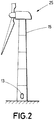
Figure 2 shows a wind turbine comprising a tower in accordance with the invention described. -
Figures 3A and 3B show respective schematic elevational (figure 3A ) and plan (figure 3B ) views of an embodiment of a tower in accordance with an example of the present invention. -
Figure 4 shows an example of two parts of the frame formed from initial parts which are longitudinal profiles. -
Figure 5 shows a preferred embodiment of the invention, wherein the intersection between the mid-planes corresponding to two adjacent parts of the frame is tangential to the mid-surface of the tower wall and also that the intersection of the mid-plane of a part with a lateral surface of said part is tangential to the mid-surface of the tower wall. -
Figure 6 shows a preferred embodiment of the invention, wherein the mid-plane of one of the parts of the frame is tangential to the mid-surface of the wall. -
Figure 7 shows a preferred embodiment of the invention, wherein the mid-plane of one of the parts of the frame is displaced, with respect to the mid-surface of the tower wall, outwards in a radial direction in order not to intersect with said mid-surface. -
Figures 8A and 8B show elevational and plan views (section along plane VIII-VIII) of an embodiment of the tower of the invention wherein the frame comprises more than two assembled longitudinal parts. -
Figures 9A and 9B show elevational and plan views (section along plane IX-IX) of a tower that incorporates a frame and a door according to a preferred embodiment. - Following is a detailed description of the present invention, with the help of the aforementioned attached
figures 1 to 9 , in addition to two preferred embodiments thereof. - The present invention relates, as can be observed in
figures 3A and 3B , to a curved cross-section tower (15) for a wind turbine (25), seefigure 2 , wherein the tower (15) is formed by a plurality of sections (10) having a curved cross-section, said sections (10) preferably being truncated cone-shaped with a circular cross-section and, therefore, having an outer surface defined, at least partially, by means of generatrices. Without loss of generality, the sections (10) may adopt any other shape defined by generatrices, for example, cylindrical. - Each of the sections (10) comprise their corresponding outer wall (11). An orifice (12) for accessing the interior of said tower (15) is included in the wall (11) of one of the sections (10), specifically a lower section (10) that constitutes the base of the tower (15), and a reinforcing frame (13) is additionally incorporated, mounted on the perimeter of the orifice (12).
- The perimeter comprises, in turn, two longitudinal zones oriented along the direction of corresponding generatrices of the tower (15), wherein the aforementioned longitudinal zones are located one on the right side and the other on the left side of the orifice. Additionally, the perimeter comprises two transverse zones, i.e. an upper and a lower zone, for connecting the two longitudinal zones one to each other. The transverse zones are affected by the curvature of the tower (15), while the longitudinal zones, due to their orientation along generatrices, are not affected by said curvature.
- The frame (13) comprises a plurality of parts (14), preferably metallic, endowed with corresponding thicknesses, and which are joined together at least in the transverse zones adjacently along the perimeter of the orifice (12), such that the thickness of the wall of the section (10) in the orifice (12) zone is fully contained in the thickness of each of the parts (14).
- In accordance with the present invention, each of the parts (14) has a mid-plane (20) which is parallel to at least one generatrix of the tower (15), as well as the mid-planes (20) of at least two adjacent parts (14) which are joined together form an angle other than 180° with respect to each other to adapt to the curvature of the wall (11) of the tower (15) in the transverse zones of the orifice (12), as shown, for example, in
figures 3A and 3B . The mid-plane (20) of each part (14) occupies a central position with respect to the thickness of its corresponding part (14). - In order to join the parts (14) to each other and/or to the tower (15) wall (11), it is preferable to use welding, preferably butt welding, due to being a particularly effective and maintenance-free procedure.
- Likewise, in order to facilitate the joint joining the parts (14) to each other, at least one of the parts (14) has a joining surface (24) on one end for being joined to an adjacent part (14), said joining surface (24) being inclined with respect to the mid-plane (20), i.e. forming an angle other than 90° with said mid-plane (20).
- Furthermore, it is also preferable for at least one of the parts (14) to have at least one curved section, wherein said part (14) can even be completely curved. In particular, it is preferable to obtain the curved part (14) by curving a prismatic, generally straight, element, and which preferably has a hollow cross-section. The curved shape of the part (14) can alternatively be obtained by cutting a flat element, such as a flat plate.
- As will be explained later and in greater detail, the position of the mid-planes (20) of the parts (14) with respect to the mid-surface of a wall (11) of the tower (15) can have different effects.
- In particular, the mid-plane (20) of at least one of the parts (14) can be secant to the mid-surface (21) of the tower (15) wall (11). "Mid-surface (21)" is understood to be the surface which, congruently to that of the tower (15) wall (11), i.e. in this case in a truncated cone-shaped manner, equally divides the tower (15) wall (11) with respect to the thickness. Likewise, the mid-planes (20) of a pair of adjacent parts (14) can define a first intersection (A) therebetween which is tangential to the mid-surface (21) of the wall (11) of the tower (15). Additionally, each part (14) can also comprise a lateral surface (22), whereby the part (14) is joined to the wall (11) of the tower (15), wherein the mid-plane (20) of a part (14) defines, with its lateral surface (22), a second intersection (B) tangential to the mid-surface (21) of the wall (11) of the tower (15).
- Alternatively, the mid-plane (20) of at least one of the parts (14) can be tangential to the aforementioned mid-surface (21). The mid-plane (20) of at least one of the parts (14) may also be displaced with respect to the mid-surface (21), outwards in a radial direction, in order not to intersect with said mid-surface (21).
- Following is a description of a first, more preferred, embodiment with the help of
figures 3A, 3B and4 to7 , wherein the parts (14) consist of two parts (14), which in turn comprise a middle section (16), in addition to an upper (17) and lower section (18) which respectively extend, above and below, from the middle section (16), towards the corresponding upper section (17) or lower (18) section of the other part (14), to be assembled. The two parts (14) are shown infigures 3A and 3B one on either side, right and left. In the example shown, the middle sections (16) are straight and are mounted on the longitudinal zone of the perimeter of the orifice (12); likewise, the upper (17) and lower (18) sections extend from the middle section (16) towards the corresponding upper (17) and lower (18) section of the other part (14), to be assembled in the transverse zone. In this way, the frame (13) can be conformed to the curvature of the tower (15) using only two parts (14). - As can be observed in the example shown, the two parts (14) are preferably symmetrical to one another with respect to a central plane (e) of the orifice (12), which is oriented along a generatrix. Preferably, the upper (17) and lower (18) sections of the parts (14) are endowed with a curved shape to conform to the perimeter of a curved orifice which makes it possible to reduce stress concentration at the base of the tower (15).
- As shown in
figure 4 , in accordance with a more preferred embodiment, the parts (14) and, more specifically, the curved shape of the upper (17) and lower (18) sections, are configured by means of curving and/or bending as of initial parts (19), preferably straight, more preferably longitudinal profiles. - Alternatively, the parts (14) can be obtained from a flat plate by cutting. This avoids the bending of longitudinal profiles which, in high-inertia profiles such as those proposed by the invention, can be very difficult.
- On the contrary, the previously described bending of the initial longitudinal parts (19) has the advantage of optimising the material, as well as allowing the obtainment of frames (13) with structurally more appropriate geometries (for example, double T-shaped beams, hollow cross-sections, etc.).
- In accordance with a second preferred embodiment, shown in
figures 8A and 8B , each of the parts (14) that make up the frame (13) are straight elements, thereby avoiding the curving of the parts (14) or the wastage of material associated with the cutting of curved elements from flat plates. In this case it is convenient for the frame (13) to be formed from a larger number of parts (14) joined to each other, such that the mid-planes (20) of the adjacent parts (14) form an angle other than 180° with respect to each other, than in the case of a frame (13) formed from curved parts (14). - It is preferable for the initial, longitudinal, parts (19) to have a uniform cross-section (for the sake of simplicity, so as to allow the use of commercial profiles), whether open or closed. Also, in the case of closed cross-sections, these may be hollow or solid. Thus, for example, the initial parts (19) may be profiles with a rectangular/square or circular hollow cross-section. In the case of rectangular or square cross-sections, the joint joining the frame (13) to the tower (15) is facilitated on having flat surfaces disposed in opposition to the tower (15) wall (11) in the joint zone.
- Since the invention is aimed mainly at optimising, from the viewpoint of resistance of the tower (15) and use of material, the joint joining a frame (13) formed from flat parts (14) or parts (14) with a curvature contained on a plane in a curved orifice (12), different criteria can be taken into account, in general related to the distribution of stresses, to determine the position of the parts (14) with respect to each other and with respect to the tower (15). Some positioning criteria of the parts (14) are explained below with the help of
figures 5 to 7 . - In accordance with a first positioning criterion, the mid-plane (20) of at least one of the parts (14) is secant to the mid-surface (21) of the wall (11) of the tower (15). In this manner, the resistance of the joint joining the frame (13) to the tower (15) is uniform throughout the frame (13)-tower (15) joint, as greater frame (13)-tower (15) joint symmetry is obtained along the entire perimeter of the orifice (12). Additionally, according to said first positioning criterion, as shown in
figure 5 , a first intersection (A) between the mid-planes (20) corresponding to two adjacent parts (14) is preferably tangential to the mid-surface of the wall (11). This ensures that the joint joining the frame (13) to the tower (15) is more resistant in the zone wherein the two adjacent parts (14) are joined together, as greater frame (13)-tower (15) joint symmetry is obtained in the joining zone between the parts (14). - In accordance with said first criterion, a second intersection (B) of the mid-plane (20) of a part (14) with a lateral surface (22) of said part (14) whereby it is joined to the wall (11) of the tower (15), is preferably tangential to the mid-surface (21) of the tower (15) wall (11). That is, in a plan view, the second intersection (B) is included within a median line that represents the mid-surface (21). In this manner, the frame (13)-tower (15) joint is reinforced in the central zone (16) of each part (14), wherefrom the upper (17) and lower (18) sections extend.
- In accordance with a second criterion, as can be observed in
figure 6 , the mid-plane (20) of at least one of the parts (14) is tangential to the mid-surface (21) of the tower (15) wall (11). In this manner, the frame (13)-tower (15) joint is reinforced in the zone wherein the mid-plane (20) is tangential to the mid-surface (21) of the tower. This makes it possible to locate the most resistant zone of the joint in the orifice (12) zone where the greatest stresses are found. - In accordance with a third criterion (see
figure 7 ), the mid-plane (20) of at least one of the parts (14) is displaced with respect to the mid-surface (21) of the tower (15), outwards in a radial direction, so as not to intersect with said mid-surface (21). - The tower (15) of the invention can additionally comprise, as shown in
figure 9 , a door (23), endowed with door thickness, and mounted on the frame (13) to seal the orifice (12) where, preferably, in a closed position, the door (23) thickness is fully contained in the frame (13) thickness.
Claims (18)
- A curved cross-section wind turbine (25) tower (15), comprising:- a wall (11), featuring a curvature, as well as having an orifice (12) for accessing inside the tower (15), and an outer surface defined by generatrices, the orifice (12) being limited by a perimeter which comprises two longitudinal zones oriented along the direction of said generatrices of the tower (15) and two transverse zones connecting the two longitudinal zones one to each other, and- a reinforcing frame (13), disposed internally to and along the perimeter of the orifice (12) and joined to the tower (15) in the orifice (12) zone, wherein the reinforcing frame (13) comprises at least two parts (14) joined together,
wherein the at least two parts (14) are adjacent and joined together at least in one of the transverse zones, wherein each of the parts (14) has a mid-plane (20) which is parallel to at least one generatrix of the tower (15) and which occupies a central position with respect to the thickness of its corresponding part (14), characterized in that the mid-planes (20) of at least two adjacent parts (14) form an angle other than 180º with respect to each other, so as to adapt the reinforcing frame (13) to the curvature of the wall (11) in the transverse zones of the orifice (12). - The wind turbine (25) tower (15), according to claim 1, characterised in that at least one of the parts (14) has, on one end, a joining surface (24) for joining to a corresponding adjacent part (14), wherein the joining surface (24) of any one of the parts (14) forms an angle other than 90º with the mid-plane (20) of said part (14).
- The wind turbine (25) tower (15), according to any one of the preceding claims, characterised in that at least one of the parts (14) has at least one curved section.
- The wind turbine (25) tower (15), according to claim 3, characterised in that the at least one part (14) having at least one curved section comprises a curved or bent prismatic element.
- The wind turbine (25) tower (15), according to claim 4, characterised in that the prismatic element has a hollow cross-section.
- The wind turbine (25) tower (15), according to claim 3, characterised in that the at least one part (14) having at least one curved section is cut out from a flat element.
- The wind turbine (25) tower (15), according to any one of the preceding claims, characterised in that the parts (14) are joined together by means of welded joints.
- The wind turbine (25) tower (15), according to any one of the preceding claims, characterised in that the mid-plane (20) of at least one of the parts (14) is secant to a mid-surface (21) of the tower (15) wall (11), wherein the mid surface is a surface which is congruent to that of the tower (15) wall (11) and equally divides the tower (15) wall (11) with respect to the thickness.
- The wind turbine (25) tower (15), according to claim 8, characterised in that the mid-plane (20) of one part (14) of a pair of adjacent parts (14) define a first intersection (A) with the mid-plane (20) of the other part (14) of said pair of adjacent parts (14), wherein the first intersection (A) is tangential to the mid-surface (21) of the wall (11) of the tower (15).
- The wind turbine (25) tower (15), according to claim 8, characterised in that each part (14) also comprises a lateral surface (22) whereby the part (14) is joined to the tower (15) wall (11), wherein the mid-plane (20) of a part (14) defines, with the lateral surface (22) of the part (14), a second intersection (B) tangential to the mid-surface (21) of the wall (11) of the tower (15).
- The wind turbine (25) tower (15), according to any one of claims 1 to 7, characterised in that the mid-plane (20) of at least one of the parts (14) is tangential to a mid-surface (21) of the wall (11) of the tower (15).
- The wind turbine (25) tower (15) according to any one of claims 1 to 7, characterised in that the mid-plane (20) of at least one of the parts (14) is displaced with respect to the mid-surface (21) of the tower (15) outwards in a radial direction so as not to intersect with said mid-surface (21).
- The wind turbine (25) tower (15), according to any of the preceding claims, characterised in that the parts (14) consist of two parts (14), each of which, in turn, comprises:- a middle section (16), and- an upper section (17) and a lower section (18) that respectively extend, in order to be assembled above and below the middle section (16) towards the corresponding upper (17) or lower (18) section of the other one of the two parts (14).
- The wind turbine (25) tower (15), according to claim 13, characterised in that the two parts (14) are symmetrical to one another with respect to a central axis (e) of the orifice (12) which is oriented along the direction of a generatrix.
- The wind turbine (25) tower (15), according to any one of claims 13 and 14, characterised in that the upper (17) and lower (18) sections have a curved shape.
- The wind turbine (25) tower (15), according to any of claims 1 to 12, characterised in that each of the parts (14) of the reinforcing frame (13) are straight elements.
- The wind turbine (25) tower (15), according to any one of the preceding claims, characterised in that it additionally comprises a door (23), endowed with a thickness, and mounted on the reinforcing frame (13) to close the orifice (12) wherein, in a closed position, the thickness of the door (23) is fully contained in the thickness of the reinforcing frame (13).
- A wind turbine (25), characterised in that it comprises the tower (15) described in any one of the preceding claims.
Priority Applications (4)
| Application Number | Priority Date | Filing Date | Title |
|---|---|---|---|
| EP15382655.7A EP3184812B1 (en) | 2015-12-22 | 2015-12-22 | Curved cross-section wind turbine tower and wind turbine comprising said tower |
| ES15382655T ES2810249T3 (en) | 2015-12-22 | 2015-12-22 | Curved section wind turbine tower, and wind turbine comprising said tower |
| DK15382655.7T DK3184812T3 (en) | 2015-12-22 | 2015-12-22 | Wind turbine tower with curved cross section and wind turbine with this tower |
| US15/385,406 US9903150B2 (en) | 2015-12-22 | 2016-12-20 | Curved cross-section wind turbine tower and wind turbine comprising said tower |
Applications Claiming Priority (1)
| Application Number | Priority Date | Filing Date | Title |
|---|---|---|---|
| EP15382655.7A EP3184812B1 (en) | 2015-12-22 | 2015-12-22 | Curved cross-section wind turbine tower and wind turbine comprising said tower |
Publications (2)
| Publication Number | Publication Date |
|---|---|
| EP3184812A1 EP3184812A1 (en) | 2017-06-28 |
| EP3184812B1 true EP3184812B1 (en) | 2020-05-06 |
Family
ID=55310610
Family Applications (1)
| Application Number | Title | Priority Date | Filing Date |
|---|---|---|---|
| EP15382655.7A Active EP3184812B1 (en) | 2015-12-22 | 2015-12-22 | Curved cross-section wind turbine tower and wind turbine comprising said tower |
Country Status (4)
| Country | Link |
|---|---|
| US (1) | US9903150B2 (en) |
| EP (1) | EP3184812B1 (en) |
| DK (1) | DK3184812T3 (en) |
| ES (1) | ES2810249T3 (en) |
Families Citing this family (4)
| Publication number | Priority date | Publication date | Assignee | Title |
|---|---|---|---|---|
| CN108000076B (en) * | 2017-12-29 | 2024-06-21 | 金风科技股份有限公司 | Manufacturing method of tower section, tower section, tower and wind turbine generator set |
| EP3825550B1 (en) * | 2019-11-21 | 2023-08-23 | Wobben Properties GmbH | Tower segment and method of manufacturing same |
| WO2022018797A1 (en) * | 2020-07-20 | 2022-01-27 | ベステラ株式会社 | Method for disassembling tower-type wind power generation facility |
| CN117913499B (en) * | 2024-01-24 | 2024-09-24 | 宁夏驭星属陈航天科技有限公司 | Large-caliber satellite measurement and control antenna |
Family Cites Families (12)
| Publication number | Priority date | Publication date | Assignee | Title |
|---|---|---|---|---|
| GB599929A (en) * | 1945-07-02 | 1948-03-24 | Board & Company Ltd | Improvements in or relating to columns for lighting or other purposes |
| JP4355949B2 (en) * | 2002-10-01 | 2009-11-04 | ゼネラル・エレクトリック・カンパニイ | Modular kit for wind turbine tower |
| DK1856410T4 (en) * | 2004-11-10 | 2018-08-27 | Vestas Wind Sys As | A WINDOW FOR A WINDMILL, A PROCEDURE FOR MANUFACTURING A TOWER AND APPLICATIONS THEREOF |
| BRPI0621047A2 (en) * | 2006-02-20 | 2011-11-29 | Vestas Wind Sys As | wind turbine tower, wind turbine, and method for building the wind turbine tower |
| US20110067322A1 (en) * | 2009-09-21 | 2011-03-24 | Taschek Richard S | Porthole Retrofit Apparatus for a Monopole Tower |
| CN201786578U (en) | 2010-08-11 | 2011-04-06 | 上海泰胜(东台)电力工程机械有限公司 | Wind power tower drum cabin door |
| US8171674B2 (en) * | 2010-12-16 | 2012-05-08 | General Electric Company | Doorway for a wind turbine tower |
| DE102012019595B3 (en) | 2012-10-05 | 2013-11-21 | E.N.O. Energy Systems Gmbh | Opening for providing ventilation in e.g. steel pipe tower of wind energy plant, has reinforcing element provided in support structure, where opening is formed by door and reinforcing element in support structure |
| DE102013016604A1 (en) * | 2013-10-07 | 2015-04-09 | EcoEnterprises GmbH | Steel tube tower of a wind turbine, as well as methods for manufacturing and assembling the tower components |
| ES2534261B1 (en) * | 2013-10-18 | 2016-02-19 | Gamesa Innovation & Technology, S.L. | Reinforced hollow for wind turbine tower |
| WO2015169968A1 (en) * | 2014-05-09 | 2015-11-12 | Doxatech Aps | Reinforcement of an access-way to a tower |
| CN104405597B (en) * | 2014-10-15 | 2018-04-03 | 新疆金风科技股份有限公司 | Doorframe, doorframe unit, the manufacture method of doorframe and the blower fan pylon of blower fan pylon |
-
2015
- 2015-12-22 EP EP15382655.7A patent/EP3184812B1/en active Active
- 2015-12-22 DK DK15382655.7T patent/DK3184812T3/en active
- 2015-12-22 ES ES15382655T patent/ES2810249T3/en active Active
-
2016
- 2016-12-20 US US15/385,406 patent/US9903150B2/en active Active
Non-Patent Citations (1)
| Title |
|---|
| None * |
Also Published As
| Publication number | Publication date |
|---|---|
| DK3184812T3 (en) | 2020-08-10 |
| US9903150B2 (en) | 2018-02-27 |
| US20170175434A1 (en) | 2017-06-22 |
| EP3184812A1 (en) | 2017-06-28 |
| ES2810249T3 (en) | 2021-03-08 |
Similar Documents
| Publication | Publication Date | Title |
|---|---|---|
| US9903150B2 (en) | Curved cross-section wind turbine tower and wind turbine comprising said tower | |
| EP2715008B1 (en) | Nodes in a truss work or a truss work like structure | |
| EP2767654B1 (en) | Flange assistant for connecting adjacent tower sections | |
| US10155545B2 (en) | Method of hot-shaping and hardening an object from a metal sheet, and a B-pillar for a vehicle | |
| CN105625585B (en) | Buckling-restrained steel structure girder column connected node and steel building | |
| KR101960671B1 (en) | Joint Structure of Circular Hollow Tube Truss and it's Fabrication Method | |
| US20130020440A1 (en) | Structure for joining torsion boxes in an aircraft using a triform fitting made from non-metallic composite materials | |
| CN102251784A (en) | Double-layer lining shield tunnel duct piece and lining superposed structure | |
| JP6151767B2 (en) | Metal link plate for energy chain chain links | |
| KR101212341B1 (en) | Single Layer Free Form Node | |
| JP2018059396A (en) | Synthetic concrete filled steel segment | |
| KR101202063B1 (en) | A fabrication type lattice girder | |
| CN109477339A (en) | Large manipulator with weight-optimized articulated mast | |
| AU2020392730B2 (en) | Main girder of bridge crane | |
| CN104564533A (en) | Reinforced hollow for a wind turbine tower | |
| CN112160241A (en) | An orthotropic steel bridge deck fatigue reinforcement structure and its construction method | |
| CN207194147U (en) | A kind of new quadrate steel pipe column and the full assembled connecting node of H profile steel beam | |
| JP5656065B2 (en) | Structural member of steel plate concrete structure | |
| CN207657820U (en) | A kind of body construction of straddle-type single-track vehicle | |
| US20120137627A1 (en) | Method of forming multi layered netlock girder system | |
| CN209145072U (en) | Have both the shear wall segmented reinforcing bar coupling beam of load-bearing and the dual function that consumes energy | |
| CN211447287U (en) | Building steel structure convenient to assembly | |
| CN210288713U (en) | A reinforcement connection structure for building design's girder and secondary beam | |
| CN209145073U (en) | Have both the shear wall segmented steel coupling beam of load-bearing and the dual function that consumes energy | |
| JP2008184898A (en) | Beam reinforcement structure |
Legal Events
| Date | Code | Title | Description |
|---|---|---|---|
| PUAI | Public reference made under article 153(3) epc to a published international application that has entered the european phase |
Free format text: ORIGINAL CODE: 0009012 |
|
| STAA | Information on the status of an ep patent application or granted ep patent |
Free format text: STATUS: THE APPLICATION HAS BEEN PUBLISHED |
|
| AK | Designated contracting states |
Kind code of ref document: A1 Designated state(s): AL AT BE BG CH CY CZ DE DK EE ES FI FR GB GR HR HU IE IS IT LI LT LU LV MC MK MT NL NO PL PT RO RS SE SI SK SM TR |
|
| AX | Request for extension of the european patent |
Extension state: BA ME |
|
| STAA | Information on the status of an ep patent application or granted ep patent |
Free format text: STATUS: REQUEST FOR EXAMINATION WAS MADE |
|
| 17P | Request for examination filed |
Effective date: 20171222 |
|
| RBV | Designated contracting states (corrected) |
Designated state(s): AL AT BE BG CH CY CZ DE DK EE ES FI FR GB GR HR HU IE IS IT LI LT LU LV MC MK MT NL NO PL PT RO RS SE SI SK SM TR |
|
| STAA | Information on the status of an ep patent application or granted ep patent |
Free format text: STATUS: EXAMINATION IS IN PROGRESS |
|
| 17Q | First examination report despatched |
Effective date: 20180716 |
|
| GRAP | Despatch of communication of intention to grant a patent |
Free format text: ORIGINAL CODE: EPIDOSNIGR1 |
|
| STAA | Information on the status of an ep patent application or granted ep patent |
Free format text: STATUS: GRANT OF PATENT IS INTENDED |
|
| INTG | Intention to grant announced |
Effective date: 20200113 |
|
| GRAS | Grant fee paid |
Free format text: ORIGINAL CODE: EPIDOSNIGR3 |
|
| GRAA | (expected) grant |
Free format text: ORIGINAL CODE: 0009210 |
|
| STAA | Information on the status of an ep patent application or granted ep patent |
Free format text: STATUS: THE PATENT HAS BEEN GRANTED |
|
| RAP1 | Party data changed (applicant data changed or rights of an application transferred) |
Owner name: NORDEX ENERGY SPAIN, S.A.U. |
|
| AK | Designated contracting states |
Kind code of ref document: B1 Designated state(s): AL AT BE BG CH CY CZ DE DK EE ES FI FR GB GR HR HU IE IS IT LI LT LU LV MC MK MT NL NO PL PT RO RS SE SI SK SM TR |
|
| REG | Reference to a national code |
Ref country code: GB Ref legal event code: FG4D |
|
| REG | Reference to a national code |
Ref country code: AT Ref legal event code: REF Ref document number: 1267157 Country of ref document: AT Kind code of ref document: T Effective date: 20200515 Ref country code: CH Ref legal event code: EP |
|
| REG | Reference to a national code |
Ref country code: IE Ref legal event code: FG4D |
|
| REG | Reference to a national code |
Ref country code: DE Ref legal event code: R096 Ref document number: 602015052102 Country of ref document: DE |
|
| REG | Reference to a national code |
Ref country code: DK Ref legal event code: T3 Effective date: 20200804 |
|
| REG | Reference to a national code |
Ref country code: LT Ref legal event code: MG4D |
|
| REG | Reference to a national code |
Ref country code: NL Ref legal event code: MP Effective date: 20200506 |
|
| PG25 | Lapsed in a contracting state [announced via postgrant information from national office to epo] |
Ref country code: FI Free format text: LAPSE BECAUSE OF FAILURE TO SUBMIT A TRANSLATION OF THE DESCRIPTION OR TO PAY THE FEE WITHIN THE PRESCRIBED TIME-LIMIT Effective date: 20200506 Ref country code: NO Free format text: LAPSE BECAUSE OF FAILURE TO SUBMIT A TRANSLATION OF THE DESCRIPTION OR TO PAY THE FEE WITHIN THE PRESCRIBED TIME-LIMIT Effective date: 20200806 Ref country code: GR Free format text: LAPSE BECAUSE OF FAILURE TO SUBMIT A TRANSLATION OF THE DESCRIPTION OR TO PAY THE FEE WITHIN THE PRESCRIBED TIME-LIMIT Effective date: 20200807 Ref country code: PT Free format text: LAPSE BECAUSE OF FAILURE TO SUBMIT A TRANSLATION OF THE DESCRIPTION OR TO PAY THE FEE WITHIN THE PRESCRIBED TIME-LIMIT Effective date: 20200907 Ref country code: IS Free format text: LAPSE BECAUSE OF FAILURE TO SUBMIT A TRANSLATION OF THE DESCRIPTION OR TO PAY THE FEE WITHIN THE PRESCRIBED TIME-LIMIT Effective date: 20200906 Ref country code: LT Free format text: LAPSE BECAUSE OF FAILURE TO SUBMIT A TRANSLATION OF THE DESCRIPTION OR TO PAY THE FEE WITHIN THE PRESCRIBED TIME-LIMIT Effective date: 20200506 Ref country code: SE Free format text: LAPSE BECAUSE OF FAILURE TO SUBMIT A TRANSLATION OF THE DESCRIPTION OR TO PAY THE FEE WITHIN THE PRESCRIBED TIME-LIMIT Effective date: 20200506 |
|
| PG25 | Lapsed in a contracting state [announced via postgrant information from national office to epo] |
Ref country code: RS Free format text: LAPSE BECAUSE OF FAILURE TO SUBMIT A TRANSLATION OF THE DESCRIPTION OR TO PAY THE FEE WITHIN THE PRESCRIBED TIME-LIMIT Effective date: 20200506 Ref country code: BG Free format text: LAPSE BECAUSE OF FAILURE TO SUBMIT A TRANSLATION OF THE DESCRIPTION OR TO PAY THE FEE WITHIN THE PRESCRIBED TIME-LIMIT Effective date: 20200806 Ref country code: HR Free format text: LAPSE BECAUSE OF FAILURE TO SUBMIT A TRANSLATION OF THE DESCRIPTION OR TO PAY THE FEE WITHIN THE PRESCRIBED TIME-LIMIT Effective date: 20200506 Ref country code: LV Free format text: LAPSE BECAUSE OF FAILURE TO SUBMIT A TRANSLATION OF THE DESCRIPTION OR TO PAY THE FEE WITHIN THE PRESCRIBED TIME-LIMIT Effective date: 20200506 |
|
| REG | Reference to a national code |
Ref country code: AT Ref legal event code: MK05 Ref document number: 1267157 Country of ref document: AT Kind code of ref document: T Effective date: 20200506 |
|
| PG25 | Lapsed in a contracting state [announced via postgrant information from national office to epo] |
Ref country code: NL Free format text: LAPSE BECAUSE OF FAILURE TO SUBMIT A TRANSLATION OF THE DESCRIPTION OR TO PAY THE FEE WITHIN THE PRESCRIBED TIME-LIMIT Effective date: 20200506 Ref country code: AL Free format text: LAPSE BECAUSE OF FAILURE TO SUBMIT A TRANSLATION OF THE DESCRIPTION OR TO PAY THE FEE WITHIN THE PRESCRIBED TIME-LIMIT Effective date: 20200506 |
|
| PG25 | Lapsed in a contracting state [announced via postgrant information from national office to epo] |
Ref country code: SM Free format text: LAPSE BECAUSE OF FAILURE TO SUBMIT A TRANSLATION OF THE DESCRIPTION OR TO PAY THE FEE WITHIN THE PRESCRIBED TIME-LIMIT Effective date: 20200506 Ref country code: EE Free format text: LAPSE BECAUSE OF FAILURE TO SUBMIT A TRANSLATION OF THE DESCRIPTION OR TO PAY THE FEE WITHIN THE PRESCRIBED TIME-LIMIT Effective date: 20200506 Ref country code: AT Free format text: LAPSE BECAUSE OF FAILURE TO SUBMIT A TRANSLATION OF THE DESCRIPTION OR TO PAY THE FEE WITHIN THE PRESCRIBED TIME-LIMIT Effective date: 20200506 Ref country code: RO Free format text: LAPSE BECAUSE OF FAILURE TO SUBMIT A TRANSLATION OF THE DESCRIPTION OR TO PAY THE FEE WITHIN THE PRESCRIBED TIME-LIMIT Effective date: 20200506 Ref country code: CZ Free format text: LAPSE BECAUSE OF FAILURE TO SUBMIT A TRANSLATION OF THE DESCRIPTION OR TO PAY THE FEE WITHIN THE PRESCRIBED TIME-LIMIT Effective date: 20200506 Ref country code: IT Free format text: LAPSE BECAUSE OF FAILURE TO SUBMIT A TRANSLATION OF THE DESCRIPTION OR TO PAY THE FEE WITHIN THE PRESCRIBED TIME-LIMIT Effective date: 20200506 |
|
| REG | Reference to a national code |
Ref country code: DE Ref legal event code: R097 Ref document number: 602015052102 Country of ref document: DE |
|
| PG25 | Lapsed in a contracting state [announced via postgrant information from national office to epo] |
Ref country code: PL Free format text: LAPSE BECAUSE OF FAILURE TO SUBMIT A TRANSLATION OF THE DESCRIPTION OR TO PAY THE FEE WITHIN THE PRESCRIBED TIME-LIMIT Effective date: 20200506 Ref country code: SK Free format text: LAPSE BECAUSE OF FAILURE TO SUBMIT A TRANSLATION OF THE DESCRIPTION OR TO PAY THE FEE WITHIN THE PRESCRIBED TIME-LIMIT Effective date: 20200506 |
|
| REG | Reference to a national code |
Ref country code: ES Ref legal event code: FG2A Ref document number: 2810249 Country of ref document: ES Kind code of ref document: T3 Effective date: 20210308 |
|
| PLBE | No opposition filed within time limit |
Free format text: ORIGINAL CODE: 0009261 |
|
| STAA | Information on the status of an ep patent application or granted ep patent |
Free format text: STATUS: NO OPPOSITION FILED WITHIN TIME LIMIT |
|
| 26N | No opposition filed |
Effective date: 20210209 |
|
| PG25 | Lapsed in a contracting state [announced via postgrant information from national office to epo] |
Ref country code: SI Free format text: LAPSE BECAUSE OF FAILURE TO SUBMIT A TRANSLATION OF THE DESCRIPTION OR TO PAY THE FEE WITHIN THE PRESCRIBED TIME-LIMIT Effective date: 20200506 |
|
| REG | Reference to a national code |
Ref country code: CH Ref legal event code: PL |
|
| GBPC | Gb: european patent ceased through non-payment of renewal fee |
Effective date: 20201222 |
|
| PG25 | Lapsed in a contracting state [announced via postgrant information from national office to epo] |
Ref country code: MC Free format text: LAPSE BECAUSE OF FAILURE TO SUBMIT A TRANSLATION OF THE DESCRIPTION OR TO PAY THE FEE WITHIN THE PRESCRIBED TIME-LIMIT Effective date: 20200506 |
|
| REG | Reference to a national code |
Ref country code: BE Ref legal event code: MM Effective date: 20201231 |
|
| PG25 | Lapsed in a contracting state [announced via postgrant information from national office to epo] |
Ref country code: FR Free format text: LAPSE BECAUSE OF NON-PAYMENT OF DUE FEES Effective date: 20201231 Ref country code: LU Free format text: LAPSE BECAUSE OF NON-PAYMENT OF DUE FEES Effective date: 20201222 Ref country code: IE Free format text: LAPSE BECAUSE OF NON-PAYMENT OF DUE FEES Effective date: 20201222 |
|
| PG25 | Lapsed in a contracting state [announced via postgrant information from national office to epo] |
Ref country code: GB Free format text: LAPSE BECAUSE OF NON-PAYMENT OF DUE FEES Effective date: 20201222 Ref country code: LI Free format text: LAPSE BECAUSE OF NON-PAYMENT OF DUE FEES Effective date: 20201231 Ref country code: CH Free format text: LAPSE BECAUSE OF NON-PAYMENT OF DUE FEES Effective date: 20201231 |
|
| PG25 | Lapsed in a contracting state [announced via postgrant information from national office to epo] |
Ref country code: TR Free format text: LAPSE BECAUSE OF FAILURE TO SUBMIT A TRANSLATION OF THE DESCRIPTION OR TO PAY THE FEE WITHIN THE PRESCRIBED TIME-LIMIT Effective date: 20200506 Ref country code: MT Free format text: LAPSE BECAUSE OF FAILURE TO SUBMIT A TRANSLATION OF THE DESCRIPTION OR TO PAY THE FEE WITHIN THE PRESCRIBED TIME-LIMIT Effective date: 20200506 Ref country code: CY Free format text: LAPSE BECAUSE OF FAILURE TO SUBMIT A TRANSLATION OF THE DESCRIPTION OR TO PAY THE FEE WITHIN THE PRESCRIBED TIME-LIMIT Effective date: 20200506 |
|
| PG25 | Lapsed in a contracting state [announced via postgrant information from national office to epo] |
Ref country code: MK Free format text: LAPSE BECAUSE OF FAILURE TO SUBMIT A TRANSLATION OF THE DESCRIPTION OR TO PAY THE FEE WITHIN THE PRESCRIBED TIME-LIMIT Effective date: 20200506 |
|
| PG25 | Lapsed in a contracting state [announced via postgrant information from national office to epo] |
Ref country code: BE Free format text: LAPSE BECAUSE OF NON-PAYMENT OF DUE FEES Effective date: 20201231 |
|
| P01 | Opt-out of the competence of the unified patent court (upc) registered |
Effective date: 20230601 |
|
| PG25 | Lapsed in a contracting state [announced via postgrant information from national office to epo] |
Ref country code: IS Free format text: LAPSE BECAUSE OF NON-PAYMENT OF DUE FEES Effective date: 20200906 |
|
| PGFP | Annual fee paid to national office [announced via postgrant information from national office to epo] |
Ref country code: DK Payment date: 20251217 Year of fee payment: 11 |
|
| PGFP | Annual fee paid to national office [announced via postgrant information from national office to epo] |
Ref country code: ES Payment date: 20260119 Year of fee payment: 11 |
|
| PGFP | Annual fee paid to national office [announced via postgrant information from national office to epo] |
Ref country code: DE Payment date: 20251222 Year of fee payment: 11 |