EP3184785A1 - Device for the acquisition and conditioning of an acoustic signal generated by a source of an internal combustion engine - Google Patents
Device for the acquisition and conditioning of an acoustic signal generated by a source of an internal combustion engine Download PDFInfo
- Publication number
- EP3184785A1 EP3184785A1 EP16206080.0A EP16206080A EP3184785A1 EP 3184785 A1 EP3184785 A1 EP 3184785A1 EP 16206080 A EP16206080 A EP 16206080A EP 3184785 A1 EP3184785 A1 EP 3184785A1
- Authority
- EP
- European Patent Office
- Prior art keywords
- measuring assembly
- source
- acoustic signal
- microphones
- plane
- Prior art date
- Legal status (The legal status is an assumption and is not a legal conclusion. Google has not performed a legal analysis and makes no representation as to the accuracy of the status listed.)
- Granted
Links
Images


Classifications
-
- H—ELECTRICITY
- H04—ELECTRIC COMMUNICATION TECHNIQUE
- H04R—LOUDSPEAKERS, MICROPHONES, GRAMOPHONE PICK-UPS OR LIKE ACOUSTIC ELECTROMECHANICAL TRANSDUCERS; ELECTRIC HEARING AIDS; PUBLIC ADDRESS SYSTEMS
- H04R3/00—Circuits for transducers
- H04R3/005—Circuits for transducers for combining the signals of two or more microphones
-
- F—MECHANICAL ENGINEERING; LIGHTING; HEATING; WEAPONS; BLASTING
- F02—COMBUSTION ENGINES; HOT-GAS OR COMBUSTION-PRODUCT ENGINE PLANTS
- F02D—CONTROLLING COMBUSTION ENGINES
- F02D41/00—Electrical control of supply of combustible mixture or its constituents
- F02D41/02—Circuit arrangements for generating control signals
- F02D41/14—Introducing closed-loop corrections
- F02D41/1497—With detection of the mechanical response of the engine
-
- F—MECHANICAL ENGINEERING; LIGHTING; HEATING; WEAPONS; BLASTING
- F02—COMBUSTION ENGINES; HOT-GAS OR COMBUSTION-PRODUCT ENGINE PLANTS
- F02D—CONTROLLING COMBUSTION ENGINES
- F02D41/00—Electrical control of supply of combustible mixture or its constituents
- F02D41/0002—Controlling intake air
- F02D41/0007—Controlling intake air for control of turbo-charged or super-charged engines
-
- G—PHYSICS
- G01—MEASURING; TESTING
- G01H—MEASUREMENT OF MECHANICAL VIBRATIONS OR ULTRASONIC, SONIC OR INFRASONIC WAVES
- G01H17/00—Measuring mechanical vibrations or ultrasonic, sonic or infrasonic waves, not provided for in the other groups of this subclass
-
- G—PHYSICS
- G01—MEASURING; TESTING
- G01H—MEASUREMENT OF MECHANICAL VIBRATIONS OR ULTRASONIC, SONIC OR INFRASONIC WAVES
- G01H3/00—Measuring characteristics of vibrations by using a detector in a fluid
- G01H3/10—Amplitude; Power
- G01H3/12—Amplitude; Power by electric means
- G01H3/125—Amplitude; Power by electric means for representing acoustic field distribution
-
- G—PHYSICS
- G01—MEASURING; TESTING
- G01M—TESTING STATIC OR DYNAMIC BALANCE OF MACHINES OR STRUCTURES; TESTING OF STRUCTURES OR APPARATUS, NOT OTHERWISE PROVIDED FOR
- G01M15/00—Testing of engines
- G01M15/04—Testing internal-combustion engines
- G01M15/12—Testing internal-combustion engines by monitoring vibrations
-
- F—MECHANICAL ENGINEERING; LIGHTING; HEATING; WEAPONS; BLASTING
- F02—COMBUSTION ENGINES; HOT-GAS OR COMBUSTION-PRODUCT ENGINE PLANTS
- F02D—CONTROLLING COMBUSTION ENGINES
- F02D41/00—Electrical control of supply of combustible mixture or its constituents
- F02D41/24—Electrical control of supply of combustible mixture or its constituents characterised by the use of digital means
- F02D41/26—Electrical control of supply of combustible mixture or its constituents characterised by the use of digital means using computer, e.g. microprocessor
- F02D41/28—Interface circuits
- F02D2041/286—Interface circuits comprising means for signal processing
- F02D2041/288—Interface circuits comprising means for signal processing for performing a transformation into the frequency domain, e.g. Fourier transformation
-
- F—MECHANICAL ENGINEERING; LIGHTING; HEATING; WEAPONS; BLASTING
- F02—COMBUSTION ENGINES; HOT-GAS OR COMBUSTION-PRODUCT ENGINE PLANTS
- F02D—CONTROLLING COMBUSTION ENGINES
- F02D2200/00—Input parameters for engine control
- F02D2200/02—Input parameters for engine control the parameters being related to the engine
- F02D2200/025—Engine noise, e.g. determined by using an acoustic sensor
-
- H—ELECTRICITY
- H04—ELECTRIC COMMUNICATION TECHNIQUE
- H04R—LOUDSPEAKERS, MICROPHONES, GRAMOPHONE PICK-UPS OR LIKE ACOUSTIC ELECTROMECHANICAL TRANSDUCERS; ELECTRIC HEARING AIDS; PUBLIC ADDRESS SYSTEMS
- H04R2430/00—Signal processing covered by H04R, not provided for in its groups
- H04R2430/20—Processing of the output signals of the acoustic transducers of an array for obtaining a desired directivity characteristic
-
- H—ELECTRICITY
- H04—ELECTRIC COMMUNICATION TECHNIQUE
- H04R—LOUDSPEAKERS, MICROPHONES, GRAMOPHONE PICK-UPS OR LIKE ACOUSTIC ELECTROMECHANICAL TRANSDUCERS; ELECTRIC HEARING AIDS; PUBLIC ADDRESS SYSTEMS
- H04R2499/00—Aspects covered by H04R or H04S not otherwise provided for in their subgroups
- H04R2499/10—General applications
- H04R2499/13—Acoustic transducers and sound field adaptation in vehicles
-
- Y—GENERAL TAGGING OF NEW TECHNOLOGICAL DEVELOPMENTS; GENERAL TAGGING OF CROSS-SECTIONAL TECHNOLOGIES SPANNING OVER SEVERAL SECTIONS OF THE IPC; TECHNICAL SUBJECTS COVERED BY FORMER USPC CROSS-REFERENCE ART COLLECTIONS [XRACs] AND DIGESTS
- Y02—TECHNOLOGIES OR APPLICATIONS FOR MITIGATION OR ADAPTATION AGAINST CLIMATE CHANGE
- Y02T—CLIMATE CHANGE MITIGATION TECHNOLOGIES RELATED TO TRANSPORTATION
- Y02T10/00—Road transport of goods or passengers
- Y02T10/10—Internal combustion engine [ICE] based vehicles
- Y02T10/12—Improving ICE efficiencies
Definitions
- the present invention relates to a device for the acquisition and conditioning of an acoustic signal generated by a source arranged in the engine compartment of a vehicle.
- sensors such as microphones and/or accelerometers
- the use of sensors such as microphones and/or accelerometers is known for the acquisition of signals generated by a source inside the engine compartment which are then suitably processed by specific algorithms to obtain information concerning the components arranged in the engine compartment, such as for example the rotational speed of the turbocharger, the occurrence of knocking phenomena, ignition failure phenomena, the engine load, the closing of the intake and/or exhaust valves, etc.
- the sensors are installed directly onto the electronic control unit of the internal combustion engine or are housed on a measuring device provided with a processing unit (a microcontroller) for the signal, which is in turn connected to the electronic control unit of the internal combustion engine.
- a processing unit a microcontroller
- the document EP-A1-1843024 describes a method for controlling an internal combustion engine comprising an engine block containing rotatable members and a control unit that is physically separated from the engine block and provided with a number of sensors, which are arranged to detect the intensity of the pressure waves generated by the internal combustion engine.
- the control unit is configured to determine, depending on the intensity of the pressure waves detected by the sensors, the value of at least one operating parameter of the engine such as, for example, the speed of the rotatable members or the occurrence of knocking phenomena inside the cylinders.
- the object of the present invention is to provide a device for the acquisition and conditioning of an acoustic signal generated by a source arranged in the engine compartment of a vehicle, which is free from the drawbacks of the state of the art and which is easy and inexpensive to manufacture.
- a device for the acquisition and conditioning of an acoustic signal generated by a source arranged in the engine compartment of a vehicle is provided, as claimed in the appended claims.
- the numeral 1 indicates an internal combustion engine housed in the engine compartment of a vehicle and comprising a turbocharger 1*.
- the turbocharger 1* is, in turn, provided with a turbine 2 and a compressor 3 provided with a bladed disc 4 rotatable around a rotation axis Z, and a fixed diffuser 5.
- the compressor 3 is arranged along an intake duct (not shown), while the turbine 2 is arranged along an exhaust duct (not shown).
- the turbine 2 and the compressor 3 are connected together mechanically; in this way, the exhaust gases discharged from the cylinders (not shown) make the turbine 2 rotate at high speed, which drives the compressor 3 into rotation, so as to increase the pressure of the air fed into the intake duct.
- a device 6 is housed inside the engine compartment for the acquisition and conditioning of a sound signal S from which functional information on the turbocharger 1*, such as for example the rotational speed of the bladed disc 4, can be derived.
- the device 6 for the acquisition and conditioning of a sound signal S is arranged in a position facing and next to the turbocharger 1*.
- the device 6 for the acquisition and conditioning of a sound signal S is housed in any position of the engine compartment.
- the device 6 for the acquisition and conditioning of a sound signal comprises two measuring assemblies 7, 8, each of which is provided with respective microphones 9 configured to acquire the sound signal S along respective provenance directions X and Y.
- the two measuring assemblies 7, 8 are adapted to acquire the sound signal S along two provenance directions X and Y, which are different from one another.
- the measuring assembly 7 is constructed so as to detect the sound signal S in the provenance direction X and is provided with at least two microphones 9* oriented towards a source 10 of interest, such as for example the bladed disk 4 of the turbocharger 1*.
- the measuring assembly 8 is constructed so as to detect the sound signal S in the provenance direction Y and is provided with at least one microphone 9** which is not oriented towards the source 10 of interest.
- the microphone 9** is preferably oriented towards the surrounding environment to detect the ambient noise.
- S denotes the sound signal detected in general by the device 6 and generated by the source 10 of interest
- S X the signal detected along the provenance direction X generated by the source 10 of interest
- S Y the signal detected along the provenance direction Y generated by the source 10 of interest.
- the measuring assembly 7 is oriented towards the source 10 (i.e. is oriented along the provenance direction X) and detects the signal S X whose rate is shown in Figure 5a .
- the signal S X comprises both a high-frequency signal S S emitted by the source 10 and a signal S A generated by the surrounding environment (i.e. the so-called ambient noise) at medium-low frequencies.
- the measuring assembly 8 is oriented towards the surrounding environment (i.e. is oriented along the provenance direction Y) and detects the signal S Y whose rate is shown in Figure 5b .
- the signal S Y only comprises the signal S A emitted by the surrounding environment (i.e. only the ambient noise) at medium-low frequencies and is not affected by the signal S S emitted by the source 10.
- the signal detected by the measuring assembly 8 is used to subtract the ambient noise from the signal detected by the measuring assembly 7.
- the acquired signals S X , S Y are transmitted to a conditioning circuit 11 and to an anti-aliasing filter 12.
- the conditioning circuit 11 is constructed so as to remove a continuous frequency f in the acquired signals S X , S Y and carry out at least one amplification stage.
- the anti-aliasing filter 12 is configured to filter frequencies f higher than half of a sampling frequency f c .
- Figures 2 and 3 show a device 6 for the acquisition and conditioning which comprises a box-shaped support body 13 that is configured to house the two measuring assemblies 7, 8, the conditioning circuit 11 and the anti-aliasing filter 12.
- the support body 13 has a substantially parallelepiped shape.
- the support body 13 has the measuring assembly 7 in the area of a front wall 14 and the measuring assembly 8 in the area of a side wall 15, arranged orthogonal to the front wall 14.
- the measuring assembly 7 is formed in the area of the front wall 14 that is arranged orthogonal to the provenance direction X; whereas the measuring assembly 8 is formed in the area of the side wall 15 that is arranged orthogonal to the provenance direction Y.
- the provenance direction X is orthogonal to the provenance direction Y.
- the measuring assembly 7 comprises, respectively, at least two microphones 9*, in particular four microphones 9* arranged in two rows and two columns and equally spaced from one another.
- the measuring assembly 8 comprises, respectively, at least one microphone 9**, in particular four microphones 9** arranged in two rows and two columns and equally spaced from one another.
- the support body 13 has both the measuring assembly 7 and the measuring assembly 8 in the area of the front wall 14.
- the measuring assembly 7 comprises three microphones 9*, while the measuring assembly 8 is formed with a single microphone 9**.
- the four microphones 9 are arranged in two rows and two columns and are equally spaced from one another.
- the measuring assembly 8 is obtained by screening a microphone 9. In this way, despite being arranged with the same orientation of the microphones 9*, the microphone 9** will not be able to detect the signal S X in the provenance direction X (being screened along said provenance direction X) and can only acquire the signal S Y along the provenance direction Y.
- the detection assemblies 7, 8 are arranged in the area of the same front wall 14 of the support body 13 which is arranged orthogonal to the provenance direction X, but at least one of the microphones 9 is screened in such a way as to define the measuring assembly 8.
- the measuring assembly 7 comprises two aligned microphones 9*, while the measuring assembly 8 is formed with a single microphone 9**.
- the support body 13 has the measuring assembly 7 in the area of a front wall 14 and the measuring assembly 8 in the area of a rear wall, parallel to the front wall 14.
- the measuring assembly 7 is formed in the area of the front wall 14 that is arranged orthogonal to the provenance direction X; whereas the measuring assembly 8 is formed in the area of the rear wall.
- the provenance direction X is parallel but opposite with respect to the provenance direction Y.
- the microphones 9 that are aligned in the same row are arranged relative to one another at a predetermined distance D 1 ; whereas, the microphones 9 which overlap along the same column are arranged relative to one another at a predetermined distance D 2 .
- the distances D 1 and D 2 are calculated as better described in the description that follows.
- the microphones 9 can be arranged in any layout in which the provenance direction X is different from the provenance direction Y.
- the acquisition and conditioning device 6 exploits the principle of directionality of the sound signals S, which is based on the delay of reception by different microphones 9 of the sound signal S generated by the single source 10.
- the sound signal S emitted by the source 10 is detected both by the microphone 9' and the microphone 9", which are sampled and processed to give rise to a finite sequence of L samples, i.e. a discrete-time signal.
- This finite sequence of L samples i.e. the discrete-time signal, is then processed by means of an algorithm known as Discrete Fourier Transform (DFT).
- DFT Discrete Fourier Transform
- the Discrete Fourier Transforms DFT provide a sampled version of the spectrum of the sound signals detected both by the microphone 9' and the microphone 9", i.e. they return the values in terms of modulus (i.e. amplitude) and phase (i.e.
- the Discrete Fourier Transform DFT is a frequency sampling of the spectrum of the sound signals detected both by the microphone 9' and the microphone 9".
- Two vectors each of which comprises an L number of elements (also called bin) contain information relating to the frequency sampling of the spectrum of the sound signals detected, respectively, both by the microphone 9' and the microphone 9".
- a bin represents the discretization step of the Discrete Fourier Transform DFT.
- the L number of bins is suitably selected so as to meet both the requirements of speed and accuracy of the response and represents the discretization step of the Discrete Fourier Transform DFT.
- the information content of each of the L bins is equal to the ratio f s /L where L represents the number of bins and f s represents the sampling frequency.
- the sampling frequency fs must be at least twice the frequency of the phenomenon to be observed; on the other hand, at the same time, it is necessary to avoid increasing excessively the computational burden for the electronic control unit ECU.
- the Discrete Fourier Transforms DFT synchronously calculated for each microphone 9', 9'' are processed by a suitable algorithm to take into account the different positions of the microphones 9', 9" and generate a kind of virtual sensor for each of the measuring assemblies denoted by 7 and 8.
- the processing of the Discrete Fourier Transforms DFT synchronously calculated for each microphone 9', 9" can consist in summing the signals detected by the different microphones 9', 9'', so that any noises on a microphone 9', 9" are compensated by the data coming from the other microphone 9', 9"; or, alternatively, it is possible to correct the phase signals detected by the different microphones 9', 9” by calculating the delay (i.e. as a function of the relative distances between the microphones 9', 9" and of the position of the source 10 of interest).
- the microphone 9 detects the sound signal S with a certain delay with respect to the microphone 9' due to the additional distance ⁇ u that must be travelled by the sound pressure wave.
- This time delay in the domain of the Fourier transforms results in a phase shift equal to e -i 2 ⁇ f ⁇ .
- f is the frequency of the incident wave
- ⁇ is equal to (d / c)sin( ⁇ )
- d is the distance between the two aligned microphones 9', 9" (i.e. the distance D 1 )
- ⁇ is the angle of incidence between the plane defined by the microphones 9 and the directrix of the source 10.
- the device is provided with a further measuring assembly equipped with at least one microphone 9**.
- the measuring assembly 16 is adapted to acquire the sound signal S along a third direction, different with respect to the directions X and Y, so as to obtain a spatial directivity.
- the device 6 for the acquisition and conditioning of the sound signal S described hitherto has a few advantages.
- the device 6 is compact, has a high flexibility of positioning inside the engine compartment, and is compatible with any electronic processing unit ECU present on board the vehicle.
Landscapes
- Engineering & Computer Science (AREA)
- Physics & Mathematics (AREA)
- General Physics & Mathematics (AREA)
- Combustion & Propulsion (AREA)
- Acoustics & Sound (AREA)
- Chemical & Material Sciences (AREA)
- Mechanical Engineering (AREA)
- General Engineering & Computer Science (AREA)
- Otolaryngology (AREA)
- Health & Medical Sciences (AREA)
- General Health & Medical Sciences (AREA)
- Signal Processing (AREA)
- Remote Sensing (AREA)
- Radar, Positioning & Navigation (AREA)
- Measurement Of Mechanical Vibrations Or Ultrasonic Waves (AREA)
- Measurement Of Velocity Or Position Using Acoustic Or Ultrasonic Waves (AREA)
- Testing Of Engines (AREA)
- Combined Controls Of Internal Combustion Engines (AREA)
- Fittings On The Vehicle Exterior For Carrying Loads, And Devices For Holding Or Mounting Articles (AREA)
Abstract
Description
- The present invention relates to a device for the acquisition and conditioning of an acoustic signal generated by a source arranged in the engine compartment of a vehicle.
- In the automotive field, the use of sensors such as microphones and/or accelerometers is known for the acquisition of signals generated by a source inside the engine compartment which are then suitably processed by specific algorithms to obtain information concerning the components arranged in the engine compartment, such as for example the rotational speed of the turbocharger, the occurrence of knocking phenomena, ignition failure phenomena, the engine load, the closing of the intake and/or exhaust valves, etc.
- Typically, the sensors are installed directly onto the electronic control unit of the internal combustion engine or are housed on a measuring device provided with a processing unit (a microcontroller) for the signal, which is in turn connected to the electronic control unit of the internal combustion engine.
- For example, the document
EP-A1-1843024 describes a method for controlling an internal combustion engine comprising an engine block containing rotatable members and a control unit that is physically separated from the engine block and provided with a number of sensors, which are arranged to detect the intensity of the pressure waves generated by the internal combustion engine. The control unit is configured to determine, depending on the intensity of the pressure waves detected by the sensors, the value of at least one operating parameter of the engine such as, for example, the speed of the rotatable members or the occurrence of knocking phenomena inside the cylinders. - A solution of the above type, however, has some disadvantages. In particular, the application of the sensor directly onto the control unit of the internal combustion engine is limiting from the positioning flexibility point of view, because of the constraints imposed by the size of the electronic control unit. In addition, these solutions have considerable costs, which are related to the signal processing electronic components, which are provided on the measuring device itself.
- Therefore, the object of the present invention is to provide a device for the acquisition and conditioning of an acoustic signal generated by a source arranged in the engine compartment of a vehicle, which is free from the drawbacks of the state of the art and which is easy and inexpensive to manufacture.
- According to the present invention, a device for the acquisition and conditioning of an acoustic signal generated by a source arranged in the engine compartment of a vehicle is provided, as claimed in the appended claims.
- The present invention will now be described with reference to the accompanying drawings, which illustrate a non-limiting embodiment thereof, in which:
-
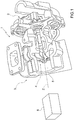
Figure 1 is a schematic view of a turbocharger for an internal combustion engine, which is facing a device for the acquisition and conditioning of an acoustic signal manufactured according to the present invention; -
Figure 2 is a schematic and perspective view of a first embodiment of the device inFigure 1 ; -
Figure 3 is a schematic and perspective view of a second embodiment of the device inFigure 1 ; -
Figure 4 is a diagram that illustrates the principle of directionality used by the device inFigures 2 and 3 ; and -
Figures 5a-5c are diagrams, in particular, spectrograms, which illustrate the acoustic signals acquired by the acquisition and conditioning device in figures from 2 to 4. - In
Figure 1 , the numeral 1 indicates an internal combustion engine housed in the engine compartment of a vehicle and comprising a turbocharger 1*. The turbocharger 1* is, in turn, provided with aturbine 2 and acompressor 3 provided with abladed disc 4 rotatable around a rotation axis Z, and afixed diffuser 5. As is known, thecompressor 3 is arranged along an intake duct (not shown), while theturbine 2 is arranged along an exhaust duct (not shown). Theturbine 2 and thecompressor 3 are connected together mechanically; in this way, the exhaust gases discharged from the cylinders (not shown) make theturbine 2 rotate at high speed, which drives thecompressor 3 into rotation, so as to increase the pressure of the air fed into the intake duct. - A
device 6 is housed inside the engine compartment for the acquisition and conditioning of a sound signal S from which functional information on the turbocharger 1*, such as for example the rotational speed of thebladed disc 4, can be derived. According to a preferred variant, thedevice 6 for the acquisition and conditioning of a sound signal S is arranged in a position facing and next to the turbocharger 1*. According to a further variant, thedevice 6 for the acquisition and conditioning of a sound signal S is housed in any position of the engine compartment. - As shown more clearly in
Figures 2 to 4 , thedevice 6 for the acquisition and conditioning of a sound signal comprises twomeasuring assemblies respective microphones 9 configured to acquire the sound signal S along respective provenance directions X and Y. In other words, the two measuringassemblies - In particular, the
measuring assembly 7 is constructed so as to detect the sound signal S in the provenance direction X and is provided with at least twomicrophones 9* oriented towards asource 10 of interest, such as for example thebladed disk 4 of the turbocharger 1*. Instead, themeasuring assembly 8 is constructed so as to detect the sound signal S in the provenance direction Y and is provided with at least onemicrophone 9** which is not oriented towards thesource 10 of interest. Themicrophone 9** is preferably oriented towards the surrounding environment to detect the ambient noise. - In the description that follows, S denotes the sound signal detected in general by the
device 6 and generated by thesource 10 of interest, SX the signal detected along the provenance direction X generated by thesource 10 of interest and SY the signal detected along the provenance direction Y generated by thesource 10 of interest. - The
measuring assembly 7 is oriented towards the source 10 (i.e. is oriented along the provenance direction X) and detects the signal SX whose rate is shown inFigure 5a . As shown in the spectrogram, the signal SX comprises both a high-frequency signal SS emitted by thesource 10 and a signal SA generated by the surrounding environment (i.e. the so-called ambient noise) at medium-low frequencies. - Instead, the
measuring assembly 8 is oriented towards the surrounding environment (i.e. is oriented along the provenance direction Y) and detects the signal SY whose rate is shown inFigure 5b . As shown in the spectrogram, the signal SY only comprises the signal SA emitted by the surrounding environment (i.e. only the ambient noise) at medium-low frequencies and is not affected by the signal SS emitted by thesource 10. The signal detected by themeasuring assembly 8 is used to subtract the ambient noise from the signal detected by themeasuring assembly 7. - The acquired signals SX, SY are transmitted to a
conditioning circuit 11 and to ananti-aliasing filter 12. Specifically, theconditioning circuit 11 is constructed so as to remove a continuous frequency f in the acquired signals SX, SY and carry out at least one amplification stage. Whereas theanti-aliasing filter 12 is configured to filter frequencies f higher than half of a sampling frequency fc. -
Figures 2 and 3 show adevice 6 for the acquisition and conditioning which comprises a box-shaped support body 13 that is configured to house the twomeasuring assemblies conditioning circuit 11 and theanti-aliasing filter 12. In the preferred embodiment, thesupport body 13 has a substantially parallelepiped shape. - According to a first embodiment shown in
Figure 2 , thesupport body 13 has themeasuring assembly 7 in the area of afront wall 14 and themeasuring assembly 8 in the area of aside wall 15, arranged orthogonal to thefront wall 14. In other words, themeasuring assembly 7 is formed in the area of thefront wall 14 that is arranged orthogonal to the provenance direction X; whereas themeasuring assembly 8 is formed in the area of theside wall 15 that is arranged orthogonal to the provenance direction Y. In this case, the provenance direction X is orthogonal to the provenance direction Y. - In this embodiment, the
measuring assembly 7 comprises, respectively, at least twomicrophones 9*, in particular fourmicrophones 9* arranged in two rows and two columns and equally spaced from one another. Similarly, themeasuring assembly 8 comprises, respectively, at least onemicrophone 9**, in particular fourmicrophones 9** arranged in two rows and two columns and equally spaced from one another. - According to a second embodiment, shown in
Figure 3 , thesupport body 13 has both themeasuring assembly 7 and themeasuring assembly 8 in the area of thefront wall 14. - In this embodiment, the
measuring assembly 7 comprises threemicrophones 9*, while themeasuring assembly 8 is formed with asingle microphone 9**. The fourmicrophones 9 are arranged in two rows and two columns and are equally spaced from one another. Themeasuring assembly 8 is obtained by screening amicrophone 9. In this way, despite being arranged with the same orientation of themicrophones 9*, themicrophone 9** will not be able to detect the signal SX in the provenance direction X (being screened along said provenance direction X) and can only acquire the signal SY along the provenance direction Y. - In other words, in this embodiment, the
detection assemblies front wall 14 of thesupport body 13 which is arranged orthogonal to the provenance direction X, but at least one of themicrophones 9 is screened in such a way as to define themeasuring assembly 8. - It is evident that further variations are possible, in which the
measuring assembly 7 comprises two alignedmicrophones 9*, while themeasuring assembly 8 is formed with asingle microphone 9**. - For instance, according to a further variant, the
support body 13 has themeasuring assembly 7 in the area of afront wall 14 and themeasuring assembly 8 in the area of a rear wall, parallel to thefront wall 14. In other words, themeasuring assembly 7 is formed in the area of thefront wall 14 that is arranged orthogonal to the provenance direction X; whereas themeasuring assembly 8 is formed in the area of the rear wall. In this case, the provenance direction X is parallel but opposite with respect to the provenance direction Y. - The
microphones 9 that are aligned in the same row are arranged relative to one another at a predetermined distance D1; whereas, themicrophones 9 which overlap along the same column are arranged relative to one another at a predetermined distance D2. The distances D1 and D2 are calculated as better described in the description that follows. - It is clear that the
microphones 9 can be arranged in any layout in which the provenance direction X is different from the provenance direction Y. - The acquisition and
conditioning device 6 exploits the principle of directionality of the sound signals S, which is based on the delay of reception bydifferent microphones 9 of the sound signal S generated by thesingle source 10. - In particular, as shown in
Figure 4 , the sound signal S emitted by thesource 10 is detected both by the microphone 9' and themicrophone 9", which are sampled and processed to give rise to a finite sequence of L samples, i.e. a discrete-time signal. This finite sequence of L samples, i.e. the discrete-time signal, is then processed by means of an algorithm known as Discrete Fourier Transform (DFT). The Discrete Fourier Transforms DFT provide a sampled version of the spectrum of the sound signals detected both by the microphone 9' and themicrophone 9", i.e. they return the values in terms of modulus (i.e. amplitude) and phase (i.e. position) that are assumed by the spectrum of the sound signals detected both by the microphone 9' and themicrophone 9" at certain equally spaced frequencies. In yet other words, the Discrete Fourier Transform DFT is a frequency sampling of the spectrum of the sound signals detected both by the microphone 9' and themicrophone 9". - Two vectors, each of which comprises an L number of elements (also called bin) contain information relating to the frequency sampling of the spectrum of the sound signals detected, respectively, both by the microphone 9' and the
microphone 9". In other words, a bin represents the discretization step of the Discrete Fourier Transform DFT. The L number of bins is suitably selected so as to meet both the requirements of speed and accuracy of the response and represents the discretization step of the Discrete Fourier Transform DFT. The information content of each of the L bins is equal to the ratio fs/L where L represents the number of bins and fs represents the sampling frequency. According to the well-known Nyquist-Shannon sampling theorem, on the one hand, the sampling frequency fs must be at least twice the frequency of the phenomenon to be observed; on the other hand, at the same time, it is necessary to avoid increasing excessively the computational burden for the electronic control unit ECU. - The Discrete Fourier Transforms DFT synchronously calculated for each microphone 9', 9'' are processed by a suitable algorithm to take into account the different positions of the
microphones 9', 9" and generate a kind of virtual sensor for each of the measuring assemblies denoted by 7 and 8. - The processing of the Discrete Fourier Transforms DFT synchronously calculated for each
microphone 9', 9" can consist in summing the signals detected by the different microphones 9', 9'', so that any noises on amicrophone 9', 9" are compensated by the data coming from theother microphone 9', 9"; or, alternatively, it is possible to correct the phase signals detected by thedifferent microphones 9', 9" by calculating the delay (i.e. as a function of the relative distances between themicrophones 9', 9" and of the position of thesource 10 of interest). - However, the sound pressure wave generated by the
source 10 is not received simultaneously by the twomicrophones 9' and 9"; themicrophone 9" detects the sound signal S with a certain delay with respect to the microphone 9' due to the additional distance Δu that must be travelled by the sound pressure wave. This time delay in the domain of the Fourier transforms results in a phase shift equal to e -i2 πfτ. Where f is the frequency of the incident wave and the quantity τ is equal to (d/c)sin(θ), where c is the speed of sound, d is the distance between the twoaligned microphones 9', 9" (i.e. the distance D1) and θ is the angle of incidence between the plane defined by themicrophones 9 and the directrix of thesource 10. By varying the angle of incidence θ, the direction of detection of the sound signal S is varied. - If the frequency f of the incident wave exceeds a threshold level fTV, a phase shift greater than 2n is obtained, which generates the sound signal S distortion phenomenon known as aliasing.
- In order to apply directionality algorithms without incurring the aliasing phenomenon, the following inequality must then prove correct:

- According to a third embodiment, not shown, the device is provided with a further measuring assembly equipped with at least one
microphone 9**. In particular, the measuring assembly 16 is adapted to acquire the sound signal S along a third direction, different with respect to the directions X and Y, so as to obtain a spatial directivity. - In the foregoing description, reference was explicitly made to the processing of the sound signal S generated by rotation of the
bladed disk 4 of the turbocharger 1*, but thedevice 6 for the acquisition and conditioning can be used for the processing of the sound signal S generated by any component arranged in the engine compartment. - It is to be understood that, depending on the phenomena to be measured or monitored, it is possible to arrange special filtering chains that allow for isolating the components at different frequencies typical of related phenomena.
- The
device 6 for the acquisition and conditioning of the sound signal S described hitherto has a few advantages. In particular, thedevice 6 is compact, has a high flexibility of positioning inside the engine compartment, and is compatible with any electronic processing unit ECU present on board the vehicle.
Claims (11)
- A device (6) for the acquisition and conditioning of a sound signal (S) generated by a source (10) of an internal combustion engine comprising a box-shaped support body (13) having a first measuring assembly (7) and a second measuring assembly (8); wherein, the first measuring assembly (7) is provided with at least two first microphones (9, 9*) which lie on a first plane (14) and are configured for the detection of a first acoustic signal (SX) generated by the source (10) along a first provenance direction (X); and wherein the second measuring assembly (8) is provided with at least a second microphone (9, 9**) arranged on a second plane (14; 15) configured for the detection of a second acoustic signal (SY) generated by the source (10) along a second provenance direction (Y) different from the first provenance direction (X).
- The device according to claim 1, wherein the first measuring assembly (7) and the second measuring assembly (8) lie on different planes.
- The device according to claim 2, wherein the first plane (14) is orthogonal to the second plane (15).
- The device according to claim 2, wherein the first plane (14) is different from, but parallel to, the second plane (15).
- The device according to any one of claims 2 to 4, wherein the first measuring assembly (7) is provided with a plurality of first microphones (9, 9*) arranged aligned in rows and columns and equally spaced from one another.
- The device according to any one of claims 2 to 5, wherein the second measuring assembly (8) is provided with a plurality of second microphones (9, 9**) arranged aligned in rows and columns and equally spaced from one another.
- The device according to claim 1, wherein the first measuring assembly (7) and the second measuring assembly (8) lie on the same plane.
- The device according to claim 5, wherein the second measuring assembly (8) is screened from the source (10).
- The device according to any one of the preceding claims, wherein the first microphones (9*) and/or the second microphones (9**) are aligned and spaced by a first distance (D1) and by a second distance (D2), respectively, from one another; wherein the first distance (D1) and the second distance (D2) are a function of the wavelength of the acoustic signal (S) acquired.
- The device according to any one of the preceding claims and comprising a third measuring assembly (16) provided with at least one microphone (9**) which lies on a third plane and is configured for the detection of a third acoustic signal generated by the source (10) along a third provenance direction different from the first and second provenance directions (X, Y).
- The device according to any one of the preceding claims and comprising a conditioning circuit (11) for the first acoustic signal (SX) and the second acoustic signal (SY); and an anti-aliasing filter (12) for the first acoustic signal (SX) and the second acoustic signal (SY).
Applications Claiming Priority (1)
| Application Number | Priority Date | Filing Date | Title |
|---|---|---|---|
| ITUB2015A009630A ITUB20159630A1 (en) | 2015-12-23 | 2015-12-23 | DEVICE FOR ACQUISITION AND CONDITIONING OF A SOUND SIGNAL GENERATED BY A SOURCE PLACED IN THE VEHICLE ENGINE COMPARTMENT |
Publications (2)
| Publication Number | Publication Date |
|---|---|
| EP3184785A1 true EP3184785A1 (en) | 2017-06-28 |
| EP3184785B1 EP3184785B1 (en) | 2020-06-17 |
Family
ID=55699689
Family Applications (1)
| Application Number | Title | Priority Date | Filing Date |
|---|---|---|---|
| EP16206080.0A Active EP3184785B1 (en) | 2015-12-23 | 2016-12-22 | Device for the acquisition and conditioning of an acoustic signal generated by a source of an internal combustion engine |
Country Status (5)
| Country | Link |
|---|---|
| US (1) | US10609478B2 (en) |
| EP (1) | EP3184785B1 (en) |
| JP (1) | JP2017125846A (en) |
| CN (1) | CN106907255B (en) |
| IT (1) | ITUB20159630A1 (en) |
Citations (4)
| Publication number | Priority date | Publication date | Assignee | Title |
|---|---|---|---|---|
| US5170433A (en) * | 1986-10-07 | 1992-12-08 | Adaptive Control Limited | Active vibration control |
| EP1843024A1 (en) | 2006-04-06 | 2007-10-10 | MAGNETI MARELLI POWERTRAIN S.p.A. | Power train control method and system |
| WO2008042884A1 (en) * | 2006-10-02 | 2008-04-10 | Wayne State University | Locating arbitrary noise sources |
| US20120169826A1 (en) * | 2011-01-04 | 2012-07-05 | Samsung Electronics Co., Ltd. | Microphone array apparatus having hidden microphone placement and acoustic signal processing apparatus including the same |
Family Cites Families (8)
| Publication number | Priority date | Publication date | Assignee | Title |
|---|---|---|---|---|
| JPS63279122A (en) * | 1987-05-12 | 1988-11-16 | Nippon Soken Inc | Apparatus for automatically searching noise source |
| JPH08328570A (en) * | 1995-05-26 | 1996-12-13 | Hino Motors Ltd | Noise reduction device in the cab of a cab-over vehicle |
| US5828760A (en) * | 1996-06-26 | 1998-10-27 | United Technologies Corporation | Non-linear reduced-phase filters for active noise control |
| JP3789685B2 (en) * | 1999-07-02 | 2006-06-28 | 富士通株式会社 | Microphone array device |
| US7349849B2 (en) * | 2001-08-08 | 2008-03-25 | Apple, Inc. | Spacing for microphone elements |
| US7539459B2 (en) * | 2004-04-02 | 2009-05-26 | Edwards Vacuum, Inc. | Active noise cancellation system, arrangement, and method |
| DE102006054603A1 (en) * | 2006-11-20 | 2008-05-21 | Robert Bosch Gmbh | Diagnosing e.g. components damages detecting, method for e.g. diesel engine of motor vehicle, involves recording sound of engine using microphone, and converting sound into electrical signal for diagnosing operating condition of engine |
| EP2180178B1 (en) * | 2008-10-21 | 2014-03-12 | Magneti Marelli S.p.A. | Method of detecting knock in an internal combustion engine |
-
2015
- 2015-12-23 IT ITUB2015A009630A patent/ITUB20159630A1/en unknown
-
2016
- 2016-12-22 EP EP16206080.0A patent/EP3184785B1/en active Active
- 2016-12-22 JP JP2016249255A patent/JP2017125846A/en active Pending
- 2016-12-22 US US15/387,949 patent/US10609478B2/en active Active
- 2016-12-23 CN CN201611208318.4A patent/CN106907255B/en active Active
Patent Citations (4)
| Publication number | Priority date | Publication date | Assignee | Title |
|---|---|---|---|---|
| US5170433A (en) * | 1986-10-07 | 1992-12-08 | Adaptive Control Limited | Active vibration control |
| EP1843024A1 (en) | 2006-04-06 | 2007-10-10 | MAGNETI MARELLI POWERTRAIN S.p.A. | Power train control method and system |
| WO2008042884A1 (en) * | 2006-10-02 | 2008-04-10 | Wayne State University | Locating arbitrary noise sources |
| US20120169826A1 (en) * | 2011-01-04 | 2012-07-05 | Samsung Electronics Co., Ltd. | Microphone array apparatus having hidden microphone placement and acoustic signal processing apparatus including the same |
Non-Patent Citations (2)
| Title |
|---|
| HEIKI TIIKOJA ET AL: "Investigations of Automotive Turbocharger Acoustics", SAE INTERNATIONAL JOURNAL OF ENGINES, vol. 4, no. 2, 15 June 2011 (2011-06-15), pages 2531 - 2542, XP055305430, ISSN: 1946-3944, DOI: 10.4271/2011-24-0221 * |
| HUIBIN LI ED - WU ET AL: "Experimental Study on the Noise Identification of the Turbocharger", 1 January 2012, ADVANCES IN COMPUTER, COMMUNICATION, CONTROL AND AUTOMATION; [LECTURE NOTES IN ELECTRICAL ENGINEERING VOL. 121 ISSN 1876-1100], BERLIN [U.A.] : SPRINGER, 2011, DE, PAGE(S) 1 - 7, ISBN: 978-3-642-25540-3, XP008181558 * |
Also Published As
| Publication number | Publication date |
|---|---|
| US20170188143A1 (en) | 2017-06-29 |
| US10609478B2 (en) | 2020-03-31 |
| JP2017125846A (en) | 2017-07-20 |
| EP3184785B1 (en) | 2020-06-17 |
| CN106907255B (en) | 2021-11-23 |
| CN106907255A (en) | 2017-06-30 |
| ITUB20159630A1 (en) | 2017-06-23 |
Similar Documents
| Publication | Publication Date | Title |
|---|---|---|
| CN104819765B (en) | Device and method for detecting at least one structure-borne sound signal | |
| EP2810453B1 (en) | Audio source position estimation | |
| US8094833B2 (en) | Sound source localization system and sound source localization method | |
| TW200936999A (en) | Knock signal detection in automotive systems | |
| US9778305B2 (en) | Pulse width measurement method and apparatus | |
| US20090285055A1 (en) | Sensor for airborne shooter localization system | |
| GB2528880A (en) | Foreign object debris detection system and method | |
| CA2915526A1 (en) | System and method for filtering noise from acoustic energy from a valve | |
| EP0671610B1 (en) | Apparatus for diagnosing sound source and vibration source | |
| US7656749B2 (en) | Systems and methods for analyzing acoustic waves | |
| JP5650420B2 (en) | Signal processing apparatus, radar apparatus, signal processing method, and signal processing program | |
| EP3184785B1 (en) | Device for the acquisition and conditioning of an acoustic signal generated by a source of an internal combustion engine | |
| JP2011099740A (en) | Minute signal detection device and method | |
| GB2104218A (en) | Detecting harmonically-rich acoustic sources | |
| US20150168545A1 (en) | Distance estimation device and method using the difference of wave speed between waves | |
| US7130242B1 (en) | System and method for detecting an acoustic signal in the presence of flow noise | |
| Gabriel et al. | Measurement of the spatial coherence of surface pressure in the wake of a car’s side mirror | |
| EP3640672B1 (en) | Systems and methods for distance independent acoustical differential signature detection | |
| GB2338540A (en) | Anti-vehicle mine | |
| KR101281057B1 (en) | System for measuring wave source | |
| Dostalek et al. | Utilization of audio source localization in security systems | |
| Ramos et al. | A modified spectral subtraction algorithm for real-time noise reduction applied to gunshot acoustics | |
| CA3058902A1 (en) | Systems and methods of capturing transient elastic vibrations in bodies using arrays of transducers for increased signal to noise ratio and source directionality | |
| JPH11344408A (en) | Sound source locator | |
| CN121634109A (en) | Rotational speed measurement device and method |
Legal Events
| Date | Code | Title | Description |
|---|---|---|---|
| PUAI | Public reference made under article 153(3) epc to a published international application that has entered the european phase |
Free format text: ORIGINAL CODE: 0009012 |
|
| STAA | Information on the status of an ep patent application or granted ep patent |
Free format text: STATUS: THE APPLICATION HAS BEEN PUBLISHED |
|
| AK | Designated contracting states |
Kind code of ref document: A1 Designated state(s): AL AT BE BG CH CY CZ DE DK EE ES FI FR GB GR HR HU IE IS IT LI LT LU LV MC MK MT NL NO PL PT RO RS SE SI SK SM TR |
|
| AX | Request for extension of the european patent |
Extension state: BA ME |
|
| STAA | Information on the status of an ep patent application or granted ep patent |
Free format text: STATUS: REQUEST FOR EXAMINATION WAS MADE |
|
| 17P | Request for examination filed |
Effective date: 20171227 |
|
| STAA | Information on the status of an ep patent application or granted ep patent |
Free format text: STATUS: EXAMINATION IS IN PROGRESS |
|
| 17Q | First examination report despatched |
Effective date: 20190625 |
|
| GRAP | Despatch of communication of intention to grant a patent |
Free format text: ORIGINAL CODE: EPIDOSNIGR1 |
|
| RIC1 | Information provided on ipc code assigned before grant |
Ipc: H04R 3/00 20060101ALI20191218BHEP Ipc: F02D 41/00 20060101AFI20191218BHEP Ipc: F02D 41/28 20060101ALN20191218BHEP Ipc: G01H 3/12 20060101ALI20191218BHEP |
|
| STAA | Information on the status of an ep patent application or granted ep patent |
Free format text: STATUS: GRANT OF PATENT IS INTENDED |
|
| INTG | Intention to grant announced |
Effective date: 20200123 |
|
| GRAS | Grant fee paid |
Free format text: ORIGINAL CODE: EPIDOSNIGR3 |
|
| GRAA | (expected) grant |
Free format text: ORIGINAL CODE: 0009210 |
|
| STAA | Information on the status of an ep patent application or granted ep patent |
Free format text: STATUS: THE PATENT HAS BEEN GRANTED |
|
| AK | Designated contracting states |
Kind code of ref document: B1 Designated state(s): AL AT BE BG CH CY CZ DE DK EE ES FI FR GB GR HR HU IE IS IT LI LT LU LV MC MK MT NL NO PL PT RO RS SE SI SK SM TR |
|
| REG | Reference to a national code |
Ref country code: GB Ref legal event code: FG4D |
|
| REG | Reference to a national code |
Ref country code: CH Ref legal event code: EP |
|
| REG | Reference to a national code |
Ref country code: IE Ref legal event code: FG4D |
|
| REG | Reference to a national code |
Ref country code: DE Ref legal event code: R096 Ref document number: 602016038155 Country of ref document: DE |
|
| REG | Reference to a national code |
Ref country code: AT Ref legal event code: REF Ref document number: 1281583 Country of ref document: AT Kind code of ref document: T Effective date: 20200715 |
|
| PG25 | Lapsed in a contracting state [announced via postgrant information from national office to epo] |
Ref country code: SE Free format text: LAPSE BECAUSE OF FAILURE TO SUBMIT A TRANSLATION OF THE DESCRIPTION OR TO PAY THE FEE WITHIN THE PRESCRIBED TIME-LIMIT Effective date: 20200617 Ref country code: NO Free format text: LAPSE BECAUSE OF FAILURE TO SUBMIT A TRANSLATION OF THE DESCRIPTION OR TO PAY THE FEE WITHIN THE PRESCRIBED TIME-LIMIT Effective date: 20200917 Ref country code: GR Free format text: LAPSE BECAUSE OF FAILURE TO SUBMIT A TRANSLATION OF THE DESCRIPTION OR TO PAY THE FEE WITHIN THE PRESCRIBED TIME-LIMIT Effective date: 20200918 Ref country code: FI Free format text: LAPSE BECAUSE OF FAILURE TO SUBMIT A TRANSLATION OF THE DESCRIPTION OR TO PAY THE FEE WITHIN THE PRESCRIBED TIME-LIMIT Effective date: 20200617 Ref country code: LT Free format text: LAPSE BECAUSE OF FAILURE TO SUBMIT A TRANSLATION OF THE DESCRIPTION OR TO PAY THE FEE WITHIN THE PRESCRIBED TIME-LIMIT Effective date: 20200617 |
|
| REG | Reference to a national code |
Ref country code: LT Ref legal event code: MG4D |
|
| REG | Reference to a national code |
Ref country code: NL Ref legal event code: MP Effective date: 20200617 |
|
| PG25 | Lapsed in a contracting state [announced via postgrant information from national office to epo] |
Ref country code: HR Free format text: LAPSE BECAUSE OF FAILURE TO SUBMIT A TRANSLATION OF THE DESCRIPTION OR TO PAY THE FEE WITHIN THE PRESCRIBED TIME-LIMIT Effective date: 20200617 Ref country code: LV Free format text: LAPSE BECAUSE OF FAILURE TO SUBMIT A TRANSLATION OF THE DESCRIPTION OR TO PAY THE FEE WITHIN THE PRESCRIBED TIME-LIMIT Effective date: 20200617 Ref country code: RS Free format text: LAPSE BECAUSE OF FAILURE TO SUBMIT A TRANSLATION OF THE DESCRIPTION OR TO PAY THE FEE WITHIN THE PRESCRIBED TIME-LIMIT Effective date: 20200617 Ref country code: BG Free format text: LAPSE BECAUSE OF FAILURE TO SUBMIT A TRANSLATION OF THE DESCRIPTION OR TO PAY THE FEE WITHIN THE PRESCRIBED TIME-LIMIT Effective date: 20200917 |
|
| REG | Reference to a national code |
Ref country code: AT Ref legal event code: MK05 Ref document number: 1281583 Country of ref document: AT Kind code of ref document: T Effective date: 20200617 |
|
| PG25 | Lapsed in a contracting state [announced via postgrant information from national office to epo] |
Ref country code: NL Free format text: LAPSE BECAUSE OF FAILURE TO SUBMIT A TRANSLATION OF THE DESCRIPTION OR TO PAY THE FEE WITHIN THE PRESCRIBED TIME-LIMIT Effective date: 20200617 Ref country code: AL Free format text: LAPSE BECAUSE OF FAILURE TO SUBMIT A TRANSLATION OF THE DESCRIPTION OR TO PAY THE FEE WITHIN THE PRESCRIBED TIME-LIMIT Effective date: 20200617 |
|
| PG25 | Lapsed in a contracting state [announced via postgrant information from national office to epo] |
Ref country code: CZ Free format text: LAPSE BECAUSE OF FAILURE TO SUBMIT A TRANSLATION OF THE DESCRIPTION OR TO PAY THE FEE WITHIN THE PRESCRIBED TIME-LIMIT Effective date: 20200617 Ref country code: ES Free format text: LAPSE BECAUSE OF FAILURE TO SUBMIT A TRANSLATION OF THE DESCRIPTION OR TO PAY THE FEE WITHIN THE PRESCRIBED TIME-LIMIT Effective date: 20200617 Ref country code: RO Free format text: LAPSE BECAUSE OF FAILURE TO SUBMIT A TRANSLATION OF THE DESCRIPTION OR TO PAY THE FEE WITHIN THE PRESCRIBED TIME-LIMIT Effective date: 20200617 Ref country code: PT Free format text: LAPSE BECAUSE OF FAILURE TO SUBMIT A TRANSLATION OF THE DESCRIPTION OR TO PAY THE FEE WITHIN THE PRESCRIBED TIME-LIMIT Effective date: 20201019 Ref country code: EE Free format text: LAPSE BECAUSE OF FAILURE TO SUBMIT A TRANSLATION OF THE DESCRIPTION OR TO PAY THE FEE WITHIN THE PRESCRIBED TIME-LIMIT Effective date: 20200617 Ref country code: AT Free format text: LAPSE BECAUSE OF FAILURE TO SUBMIT A TRANSLATION OF THE DESCRIPTION OR TO PAY THE FEE WITHIN THE PRESCRIBED TIME-LIMIT Effective date: 20200617 Ref country code: SM Free format text: LAPSE BECAUSE OF FAILURE TO SUBMIT A TRANSLATION OF THE DESCRIPTION OR TO PAY THE FEE WITHIN THE PRESCRIBED TIME-LIMIT Effective date: 20200617 |
|
| PG25 | Lapsed in a contracting state [announced via postgrant information from national office to epo] |
Ref country code: IS Free format text: LAPSE BECAUSE OF FAILURE TO SUBMIT A TRANSLATION OF THE DESCRIPTION OR TO PAY THE FEE WITHIN THE PRESCRIBED TIME-LIMIT Effective date: 20201017 Ref country code: PL Free format text: LAPSE BECAUSE OF FAILURE TO SUBMIT A TRANSLATION OF THE DESCRIPTION OR TO PAY THE FEE WITHIN THE PRESCRIBED TIME-LIMIT Effective date: 20200617 Ref country code: SK Free format text: LAPSE BECAUSE OF FAILURE TO SUBMIT A TRANSLATION OF THE DESCRIPTION OR TO PAY THE FEE WITHIN THE PRESCRIBED TIME-LIMIT Effective date: 20200617 |
|
| REG | Reference to a national code |
Ref country code: DE Ref legal event code: R097 Ref document number: 602016038155 Country of ref document: DE |
|
| PLBE | No opposition filed within time limit |
Free format text: ORIGINAL CODE: 0009261 |
|
| STAA | Information on the status of an ep patent application or granted ep patent |
Free format text: STATUS: NO OPPOSITION FILED WITHIN TIME LIMIT |
|
| PG25 | Lapsed in a contracting state [announced via postgrant information from national office to epo] |
Ref country code: DK Free format text: LAPSE BECAUSE OF FAILURE TO SUBMIT A TRANSLATION OF THE DESCRIPTION OR TO PAY THE FEE WITHIN THE PRESCRIBED TIME-LIMIT Effective date: 20200617 |
|
| 26N | No opposition filed |
Effective date: 20210318 |
|
| PG25 | Lapsed in a contracting state [announced via postgrant information from national office to epo] |
Ref country code: SI Free format text: LAPSE BECAUSE OF FAILURE TO SUBMIT A TRANSLATION OF THE DESCRIPTION OR TO PAY THE FEE WITHIN THE PRESCRIBED TIME-LIMIT Effective date: 20200617 |
|
| REG | Reference to a national code |
Ref country code: CH Ref legal event code: PL |
|
| GBPC | Gb: european patent ceased through non-payment of renewal fee |
Effective date: 20201222 |
|
| PG25 | Lapsed in a contracting state [announced via postgrant information from national office to epo] |
Ref country code: MC Free format text: LAPSE BECAUSE OF FAILURE TO SUBMIT A TRANSLATION OF THE DESCRIPTION OR TO PAY THE FEE WITHIN THE PRESCRIBED TIME-LIMIT Effective date: 20200617 |
|
| REG | Reference to a national code |
Ref country code: BE Ref legal event code: MM Effective date: 20201231 |
|
| PG25 | Lapsed in a contracting state [announced via postgrant information from national office to epo] |
Ref country code: LU Free format text: LAPSE BECAUSE OF NON-PAYMENT OF DUE FEES Effective date: 20201222 Ref country code: IE Free format text: LAPSE BECAUSE OF NON-PAYMENT OF DUE FEES Effective date: 20201222 |
|
| PG25 | Lapsed in a contracting state [announced via postgrant information from national office to epo] |
Ref country code: CH Free format text: LAPSE BECAUSE OF NON-PAYMENT OF DUE FEES Effective date: 20201231 Ref country code: LI Free format text: LAPSE BECAUSE OF NON-PAYMENT OF DUE FEES Effective date: 20201231 Ref country code: GB Free format text: LAPSE BECAUSE OF NON-PAYMENT OF DUE FEES Effective date: 20201222 |
|
| PG25 | Lapsed in a contracting state [announced via postgrant information from national office to epo] |
Ref country code: IS Free format text: LAPSE BECAUSE OF FAILURE TO SUBMIT A TRANSLATION OF THE DESCRIPTION OR TO PAY THE FEE WITHIN THE PRESCRIBED TIME-LIMIT Effective date: 20201017 Ref country code: TR Free format text: LAPSE BECAUSE OF FAILURE TO SUBMIT A TRANSLATION OF THE DESCRIPTION OR TO PAY THE FEE WITHIN THE PRESCRIBED TIME-LIMIT Effective date: 20200617 Ref country code: MT Free format text: LAPSE BECAUSE OF FAILURE TO SUBMIT A TRANSLATION OF THE DESCRIPTION OR TO PAY THE FEE WITHIN THE PRESCRIBED TIME-LIMIT Effective date: 20200617 Ref country code: CY Free format text: LAPSE BECAUSE OF FAILURE TO SUBMIT A TRANSLATION OF THE DESCRIPTION OR TO PAY THE FEE WITHIN THE PRESCRIBED TIME-LIMIT Effective date: 20200617 |
|
| PG25 | Lapsed in a contracting state [announced via postgrant information from national office to epo] |
Ref country code: MK Free format text: LAPSE BECAUSE OF FAILURE TO SUBMIT A TRANSLATION OF THE DESCRIPTION OR TO PAY THE FEE WITHIN THE PRESCRIBED TIME-LIMIT Effective date: 20200617 |
|
| PG25 | Lapsed in a contracting state [announced via postgrant information from national office to epo] |
Ref country code: BE Free format text: LAPSE BECAUSE OF NON-PAYMENT OF DUE FEES Effective date: 20201231 |
|
| PGFP | Annual fee paid to national office [announced via postgrant information from national office to epo] |
Ref country code: DE Payment date: 20251126 Year of fee payment: 10 |
|
| PGFP | Annual fee paid to national office [announced via postgrant information from national office to epo] |
Ref country code: IT Payment date: 20251119 Year of fee payment: 10 |
|
| PGFP | Annual fee paid to national office [announced via postgrant information from national office to epo] |
Ref country code: FR Payment date: 20251120 Year of fee payment: 10 |