EP3184750A1 - Impingement cooling baffle - Google Patents
Impingement cooling baffle Download PDFInfo
- Publication number
- EP3184750A1 EP3184750A1 EP16203382.3A EP16203382A EP3184750A1 EP 3184750 A1 EP3184750 A1 EP 3184750A1 EP 16203382 A EP16203382 A EP 16203382A EP 3184750 A1 EP3184750 A1 EP 3184750A1
- Authority
- EP
- European Patent Office
- Prior art keywords
- baffle
- baffle portion
- component
- cavity
- core
- Prior art date
- Legal status (The legal status is an assumption and is not a legal conclusion. Google has not performed a legal analysis and makes no representation as to the accuracy of the status listed.)
- Granted
Links
Images



Classifications
-
- F—MECHANICAL ENGINEERING; LIGHTING; HEATING; WEAPONS; BLASTING
- F01—MACHINES OR ENGINES IN GENERAL; ENGINE PLANTS IN GENERAL; STEAM ENGINES
- F01D—NON-POSITIVE DISPLACEMENT MACHINES OR ENGINES, e.g. STEAM TURBINES
- F01D9/00—Stators
- F01D9/06—Fluid supply conduits to nozzles or the like
- F01D9/065—Fluid supply or removal conduits traversing the working fluid flow, e.g. for lubrication-, cooling-, or sealing fluids
-
- F—MECHANICAL ENGINEERING; LIGHTING; HEATING; WEAPONS; BLASTING
- F01—MACHINES OR ENGINES IN GENERAL; ENGINE PLANTS IN GENERAL; STEAM ENGINES
- F01D—NON-POSITIVE DISPLACEMENT MACHINES OR ENGINES, e.g. STEAM TURBINES
- F01D25/00—Component parts, details, or accessories, not provided for in, or of interest apart from, other groups
- F01D25/08—Cooling; Heating; Heat-insulation
- F01D25/12—Cooling
-
- F—MECHANICAL ENGINEERING; LIGHTING; HEATING; WEAPONS; BLASTING
- F01—MACHINES OR ENGINES IN GENERAL; ENGINE PLANTS IN GENERAL; STEAM ENGINES
- F01D—NON-POSITIVE DISPLACEMENT MACHINES OR ENGINES, e.g. STEAM TURBINES
- F01D9/00—Stators
- F01D9/02—Nozzles; Nozzle boxes; Stator blades; Guide conduits, e.g. individual nozzles
-
- F—MECHANICAL ENGINEERING; LIGHTING; HEATING; WEAPONS; BLASTING
- F02—COMBUSTION ENGINES; HOT-GAS OR COMBUSTION-PRODUCT ENGINE PLANTS
- F02C—GAS-TURBINE PLANTS; AIR INTAKES FOR JET-PROPULSION PLANTS; CONTROLLING FUEL SUPPLY IN AIR-BREATHING JET-PROPULSION PLANTS
- F02C3/00—Gas-turbine plants characterised by the use of combustion products as the working fluid
- F02C3/04—Gas-turbine plants characterised by the use of combustion products as the working fluid having a turbine driving a compressor
-
- F—MECHANICAL ENGINEERING; LIGHTING; HEATING; WEAPONS; BLASTING
- F01—MACHINES OR ENGINES IN GENERAL; ENGINE PLANTS IN GENERAL; STEAM ENGINES
- F01D—NON-POSITIVE DISPLACEMENT MACHINES OR ENGINES, e.g. STEAM TURBINES
- F01D5/00—Blades; Blade-carrying members; Heating, heat-insulating, cooling or antivibration means on the blades or the members
- F01D5/12—Blades
- F01D5/14—Form or construction
- F01D5/18—Hollow blades, i.e. blades with cooling or heating channels or cavities; Heating, heat-insulating or cooling means on blades
- F01D5/187—Convection cooling
- F01D5/188—Convection cooling with an insert in the blade cavity to guide the cooling fluid, e.g. forming a separation wall
- F01D5/189—Convection cooling with an insert in the blade cavity to guide the cooling fluid, e.g. forming a separation wall the insert having a tubular cross-section, e.g. airfoil shape
-
- F—MECHANICAL ENGINEERING; LIGHTING; HEATING; WEAPONS; BLASTING
- F05—INDEXING SCHEMES RELATING TO ENGINES OR PUMPS IN VARIOUS SUBCLASSES OF CLASSES F01-F04
- F05D—INDEXING SCHEME FOR ASPECTS RELATING TO NON-POSITIVE-DISPLACEMENT MACHINES OR ENGINES, GAS-TURBINES OR JET-PROPULSION PLANTS
- F05D2220/00—Application
- F05D2220/30—Application in turbines
- F05D2220/32—Application in turbines in gas turbines
-
- F—MECHANICAL ENGINEERING; LIGHTING; HEATING; WEAPONS; BLASTING
- F05—INDEXING SCHEMES RELATING TO ENGINES OR PUMPS IN VARIOUS SUBCLASSES OF CLASSES F01-F04
- F05D—INDEXING SCHEME FOR ASPECTS RELATING TO NON-POSITIVE-DISPLACEMENT MACHINES OR ENGINES, GAS-TURBINES OR JET-PROPULSION PLANTS
- F05D2240/00—Components
- F05D2240/80—Platforms for stationary or moving blades
-
- F—MECHANICAL ENGINEERING; LIGHTING; HEATING; WEAPONS; BLASTING
- F05—INDEXING SCHEMES RELATING TO ENGINES OR PUMPS IN VARIOUS SUBCLASSES OF CLASSES F01-F04
- F05D—INDEXING SCHEME FOR ASPECTS RELATING TO NON-POSITIVE-DISPLACEMENT MACHINES OR ENGINES, GAS-TURBINES OR JET-PROPULSION PLANTS
- F05D2260/00—Function
- F05D2260/20—Heat transfer, e.g. cooling
- F05D2260/201—Heat transfer, e.g. cooling by impingement of a fluid
-
- Y—GENERAL TAGGING OF NEW TECHNOLOGICAL DEVELOPMENTS; GENERAL TAGGING OF CROSS-SECTIONAL TECHNOLOGIES SPANNING OVER SEVERAL SECTIONS OF THE IPC; TECHNICAL SUBJECTS COVERED BY FORMER USPC CROSS-REFERENCE ART COLLECTIONS [XRACs] AND DIGESTS
- Y02—TECHNOLOGIES OR APPLICATIONS FOR MITIGATION OR ADAPTATION AGAINST CLIMATE CHANGE
- Y02T—CLIMATE CHANGE MITIGATION TECHNOLOGIES RELATED TO TRANSPORTATION
- Y02T50/00—Aeronautics or air transport
- Y02T50/60—Efficient propulsion technologies, e.g. for aircraft
Definitions
- This disclosure relates to gas turbine engines, and more particularly to the provision of cooling air for internal components of gas turbine engines.
- Gas turbine engines such as those used to power modern commercial and military aircraft, generally include a compressor section to pressurize an airflow, a combustor section for burning hydrocarbon fuel in the presence of the pressurized air, and a turbine section to extract energy from the resultant combustion gases.
- the airflow flows along a gaspath through the gas turbine engine.
- Cooling air is directed into an interior of the component and impinged on an inner surface of the component to provide impingement cooling of the component as an alternative or in addition to film cooling.
- the cooling airflow is typically flowed through a baffle installed at the interior of the component to direct the impingement cooling airflow toward the inner surface.
- a baffle installed at the interior of the component to direct the impingement cooling airflow toward the inner surface.
- a component for a gas turbine engine includes a first component end, a second component end and a cavity extending from the first component end to the second component end.
- a baffle assembly is located in the cavity including a first baffle portion inserted into the cavity and a second baffle portion inserted into the cavity. The first baffle portion overlaps the second baffle portion.
- each of the first baffle portion and the second baffle portion include a plurality of baffle openings therethrough to direct a cooling airflow through the plurality of baffle openings to impinge on a cavity wall.
- the first baffle portion is secured to the second baffle portion.
- a press fit condition exists between the first baffle portion and the second baffle portion.
- one or more guide tabs are positioned at the second baffle portion to guide the first baffle portion over the second baffle portion.
- a cover is located at one of the first baffle portion or the second baffle portion to at least partially block the cooling airflow from passing therethrough.
- the first baffle portion includes a retention flange to retain the first baffle portion at the first component end.
- a vane for a gas turbine engine in another embodiment, includes an outer platform, an inner platform and an airfoil portion extending between the outer platform and the inner platform.
- a core defined by a core wall extends through the airfoil portion from the outer platform to the inner platform.
- a baffle is positioned in the core and is offset from the core wall. The baffle includes a first baffle portion inserted into the core and a second baffle portion inserted into the core. One of the first baffle portion or the second baffle portion overlaps the other of the first baffle portion or the second baffle portion.
- each of the first baffle portion and the second baffle portion includes a plurality of baffle openings therethrough to direct a cooling airflow through the plurality of baffle openings to impinge on a core wall.
- the first baffle portion is secured to the second baffle portion.
- a press fit condition exists between the first baffle portion and the second baffle portion.
- one or more guide tabs are located at one of the first baffle portion or the second baffle portion to guide the other of the first baffle portion or the second baffle portion thereover.
- a cover is positioned at one of the first baffle portion or the second baffle portion to at least partially block the cooling airflow from passing therethrough.
- the first baffle portion includes an outer retention flange to retain the first baffle portion at the outer platform.
- the second baffle portion includes an inner retention flange to retain the second baffle portion at the inner platform.
- a baffle offset between the baffle and the core wall is substantially constant along the airfoil portion.
- the baffle offset is in the range of 0.010 inches and 0.250 inches (0.25 mm to 6.3 mm).
- a gas turbine engine in yet another embodiment, includes a compressor section, a combustor section, a turbine section and a component including a first component end, a second component end, and a cavity extending from the first component end to the second component end.
- a baffle assembly is located in the cavity including a first baffle portion inserted into the cavity and a second baffle portion inserted into the cavity. The first baffle portion overlaps the second baffle portion.
- each of the first baffle portion and the second baffle portion includes a plurality of baffle openings therethrough to direct a cooling airflow through the plurality of baffle openings to impinge on a cavity wall.
- the first baffle portion is secured to the second baffle portion.
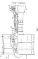
- FIG. 1 is a schematic illustration of a gas turbine engine 10.
- the gas turbine engine generally has a fan 12 through which ambient air is propelled in the direction of arrow 14, a compressor 16 for pressurizing the air received from the fan 12 and a combustor 18 wherein the compressed air is mixed with fuel and ignited for generating combustion gases.
- the gas turbine engine 10 further comprises a turbine section 20 for extracting energy from the combustion gases. Fuel is injected into the combustor 18 of the gas turbine engine 10 for mixing with the compressed air from the compressor 16 and ignition of the resultant mixture.
- the fan 12, compressor 16, combustor 18, and turbine 20 are typically all concentric about a common central longitudinal axis of the gas turbine engine 10.
- the compressor 16 includes one or more compressor rotors 26 and one or more compressor stators 28.
- the turbine 20 includes one or more turbine stators 22 including a plurality of turbine vanes 30 and one or more turbine rotors 24 including a plurality of turbine blades 32.
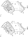
- the turbine vane 30 includes an airfoil portion 34 extending between an inner platform 36 and an outer platform 38.
- the airfoil portion 34 has a leading edge 80 and a trailing edge 82, relative to a gas flow direction 84 past the airfoil portion 34.
- the inner platform 36 is positioned nearer the engine axis, relative to the outer platform 38.
- An inner fillet 40 connects the airfoil portion 34 to the inner platform 36 and, similarly, an outer fillet 42 connects the airfoil portion 34 to the outer platform 38.
- one or more cavities, or cores 44 extend through the airfoil portion 34 and are accessible via at least one of the inner platform 36 and/or outer platform 38.
- the cores 44 are utilized to flow a cooling airflow 46 therethrough utilized to cool the turbine vane 30 and other components of the gas turbine engine 10.
- baffles 50 are installed in the core 44.
- the baffle 50 is formed from a metal material such as steel, nickel or aluminium, but it is to be appreciated that other materials may be utilized.
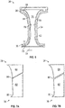
- the baffle 50 includes a plurality of baffle openings 52, and as shown in FIG. 4 , is offset from the core wall 48 by a baffle offset 54 and forms a baffle plenum 56 defined by opposing baffle walls 58.
- the baffle offset 54 is between about 0.010 inches and 0.250 inches (0.25 mm to 6.3 mm).
- the baffle walls 58 preferably follow contours of the airfoil portion 34 to increase cooling benefits from impingement.
- the placement of the baffle 50 in the core 44 and the baffle openings 52 allows the cooling airflow 46, directed from a cooling airflow source 60, into the baffle plenum 56 via the outer platform 38 and/or the inner platform 36, to be directed through the baffle openings 52 and impinge on the core wall 48.
- the airfoil portion shape and/or large inner fillets and outer fillets, make it difficult to install a baffle that extends an entire length of the airfoil portion from the inner platform to the outer platform, while still maintaining the desired baffle offset 54.
- the baffle 50 includes an inner baffle portion 62 installed via the inner platform 36 and an outer baffle portion 64 installed via the outer platform 38, with a central joint 66 where the inner baffle portion 62 and the outer baffle portion 64 meet. This allows the baffle 50 to follow the core walls 48 even when the core walls 48 diverge such as at the inner fillet 40 and the outer fillet 42. As shown in FIG.
- the outer baffle portion 64 may include an outer retention flange 68 at the outer platform 38 to position the outer baffle portion 64 at the outer platform 38.
- an inner retention flange 70 may be included at the inner baffle portion 62 to retain the inner baffle portion 62 at the inner platform 36.
- the central joint 66 may be configured to be, for example, a press fit joint or a brazed joint, though a brazed joint will require a thermal growth assessment to ensure the baffle 50 can withstand a thermal mismatch between the baffle 50 and the turbine vane 30.
- FIG. 5 An embodiment of the central joint 66 is shown in more detail in FIG. 5 .
- the outer baffle portion 64 overlaps the inner baffle portion 62, with a baffle recess 72 in the inner baffle portion 62 facilitating the overlap, while allowing for a consistent baffle offset 54 along the baffle 50 across the central joint 66.
- the inner baffle portion 62 may further include one or more guide tabs 74 at an outer end 76 of the inner baffle portion 62 to guide the outer baffle portion 64 over the inner baffle portion 62 or alternatively to guide the inner baffle portion 62 inside of the outer baffle portion 64 during assembly. Though in the embodiment of FIG.
- the outer baffle portion 64 overlaps the inner baffle portion 62
- other embodiments may be configured such that the inner baffle portion 62 overlaps the outer baffle portion 64.
- the central joint 66 is brazed to maintain the relative position of the inner baffle portion 62 and the outer baffle portion 64.
- the central joint 66 is a press fit or slip fit, allowing relative motion between the inner baffle portion 62 and the outer baffle portion 64, which may be due to thermal growth of the turbine vane 30 relative to the baffle 50.
- one of the outer baffle portion 64 or the inner baffle portion 62 may have a cover 78 positioned therein to prevent cooling airflow 46 from flowing entirely through the baffle plenum 56.
- the cooling airflow 46 may be unidirectional, flowing into the baffle plenum 56 through only one of the outer platform 38 or the inner platform 36 and out of the baffle plenum 56 through the baffle openings 52, or may be bidirectional, flowing into the baffle plenum 56 through both the outer platform 38 and the inner platform 36, and out through baffle openings 52.
- FIGS. 7A to 7F Alternative embodiments of baffle 50 arrangements are shown in FIGS. 7A to 7F , with the baffle openings 52 omitted for clarity.
- the central joint 66 is canted toward an inner platform 36 leading edge 80 with the outer baffle portion 64 overlapping the inner baffle potion 62.
- the central joint is canted similarly to that of FIG. 7A , but the inner baffle portion 62 overlaps the outer baffle portion 64.
- FIG. 7C the central joint 66 is again similarly canted to that of FIG. 7A , but the central joint 66 is located nearer to the inner platform 36.
- the central joint 66 is canted toward the outer platform 38 leading edge 80.
- the central joint 66 is not canted but is located near midspan of the airfoil portion 34 in the embodiment of FIG. 7E , and near the inner platform 36 in the embodiment of FIG. 7F .
- FIGS 7A to 7F illustrate baffles with an outer baffle portion 64 and an inner baffle portion 62 with a substantially axially-extending central joint 66
- FIG. 8 another embodiment is shown in FIG. 8 .
- the baffle 50 includes a first axial baffle portion 80 and a second axial baffle portion 82, which are joined at a substantially radially-extending central joint 66.
- Such an alternative embodiment allows for installation of baffles 50 in components where the core walls 48 converge at, for example, the outer platform 38 and/or the inner platform 36, and still have the ability to maintain a desired baffle offset 54.
Landscapes
- Engineering & Computer Science (AREA)
- Mechanical Engineering (AREA)
- General Engineering & Computer Science (AREA)
- Physics & Mathematics (AREA)
- Fluid Mechanics (AREA)
- Chemical & Material Sciences (AREA)
- Combustion & Propulsion (AREA)
- Turbine Rotor Nozzle Sealing (AREA)
Abstract
Description
- This disclosure relates to gas turbine engines, and more particularly to the provision of cooling air for internal components of gas turbine engines.
- Gas turbine engines, such as those used to power modern commercial and military aircraft, generally include a compressor section to pressurize an airflow, a combustor section for burning hydrocarbon fuel in the presence of the pressurized air, and a turbine section to extract energy from the resultant combustion gases. The airflow flows along a gaspath through the gas turbine engine.
- Operating temperatures in the turbine section and a high pressure compressor portion of the gas turbine engine often exceed a maximum useful temperature of materials used to form components in those portions of the gas turbine engine, so cooling is provided to many of these components via a flow of lower temperature cooling air drawn from other portions of the gas turbine engine. One cooling scheme utilized is the injection of cooling air along a flowpath surface of the components to form a cooling film at the component surface. In many components, such as turbine vanes, cooling air is directed into an interior of the component and impinged on an inner surface of the component to provide impingement cooling of the component as an alternative or in addition to film cooling.
- The cooling airflow is typically flowed through a baffle installed at the interior of the component to direct the impingement cooling airflow toward the inner surface. As component shapes evolve into more complex geometries to meet engine performance requirements, manufacture and installation of the baffles compatible with the complex component shapes and also enabling a required degree of impingement cooling becomes increasingly difficult.
- In one embodiment, a component for a gas turbine engine includes a first component end, a second component end and a cavity extending from the first component end to the second component end. A baffle assembly is located in the cavity including a first baffle portion inserted into the cavity and a second baffle portion inserted into the cavity. The first baffle portion overlaps the second baffle portion.
- Additionally or alternatively, in this or other embodiments each of the first baffle portion and the second baffle portion include a plurality of baffle openings therethrough to direct a cooling airflow through the plurality of baffle openings to impinge on a cavity wall.
- Additionally or alternatively, in this or other embodiments the first baffle portion is secured to the second baffle portion.
- Additionally or alternatively, in this or other embodiments a press fit condition exists between the first baffle portion and the second baffle portion.
- Additionally or alternatively, in this or other embodiments one or more guide tabs are positioned at the second baffle portion to guide the first baffle portion over the second baffle portion.
- Additionally or alternatively, in this or other embodiments a cover is located at one of the first baffle portion or the second baffle portion to at least partially block the cooling airflow from passing therethrough.
- Additionally or alternatively, in this or other embodiments the first baffle portion includes a retention flange to retain the first baffle portion at the first component end.
- In another embodiment, a vane for a gas turbine engine includes an outer platform, an inner platform and an airfoil portion extending between the outer platform and the inner platform. A core defined by a core wall extends through the airfoil portion from the outer platform to the inner platform. A baffle is positioned in the core and is offset from the core wall. The baffle includes a first baffle portion inserted into the core and a second baffle portion inserted into the core. One of the first baffle portion or the second baffle portion overlaps the other of the first baffle portion or the second baffle portion.
- Additionally or alternatively, in this or other embodiments each of the first baffle portion and the second baffle portion includes a plurality of baffle openings therethrough to direct a cooling airflow through the plurality of baffle openings to impinge on a core wall.
- Additionally or alternatively, in this or other embodiments the first baffle portion is secured to the second baffle portion.
- Additionally or alternatively, in this or other embodiments a press fit condition exists between the first baffle portion and the second baffle portion.
- Additionally or alternatively, in this or other embodiments one or more guide tabs are located at one of the first baffle portion or the second baffle portion to guide the other of the first baffle portion or the second baffle portion thereover.
- Additionally or alternatively, in this or other embodiments a cover is positioned at one of the first baffle portion or the second baffle portion to at least partially block the cooling airflow from passing therethrough.
- Additionally or alternatively, in this or other embodiments the first baffle portion includes an outer retention flange to retain the first baffle portion at the outer platform.
- Additionally or alternatively, in this or other embodiments the second baffle portion includes an inner retention flange to retain the second baffle portion at the inner platform.
- Additionally or alternatively, in this or other embodiments a baffle offset between the baffle and the core wall is substantially constant along the airfoil portion.
- Additionally or alternatively, in this or other embodiments the baffle offset is in the range of 0.010 inches and 0.250 inches (0.25 mm to 6.3 mm).
- In yet another embodiment, a gas turbine engine includes a compressor section, a combustor section, a turbine section and a component including a first component end, a second component end, and a cavity extending from the first component end to the second component end. A baffle assembly is located in the cavity including a first baffle portion inserted into the cavity and a second baffle portion inserted into the cavity. The first baffle portion overlaps the second baffle portion.
- Additionally or alternatively, in this or other embodiments each of the first baffle portion and the second baffle portion includes a plurality of baffle openings therethrough to direct a cooling airflow through the plurality of baffle openings to impinge on a cavity wall.
- Additionally or alternatively, in this or other embodiments the first baffle portion is secured to the second baffle portion.
- The subject matter which is regarded as the present disclosure is particularly pointed out and distinctly claimed in the claims at the conclusion of the specification. The foregoing and other features, and advantages of the present disclosure are apparent from the following detailed description taken in conjunction with the accompanying drawings in which:
-
FIG. 1 illustrates a schematic cross-sectional view of an embodiment of a gas turbine engine; -
FIG. 2 illustrates a perspective view of an embodiment of a turbine vane for a gas turbine engine; -
FIG. 3 illustrates a perspective view of an embodiment of a turbine vane including an impingement cooling baffle; -
FIG. 4 illustrates a cross-sectional view of an embodiment of a turbine vane including an impingement cooling baffle; -
FIG. 5 illustrates a cross-sectional view of an embodiment of a joint between portions of an impingement baffle; -
FIG. 6 illustrates a cross-sectional view of an embodiment of an impingement baffle including a cover; -
FIGS. 7A to 7F illustrate embodiments of arrangements of impingement baffle portions; and -
FIG. 8 illustrates another embodiment of a baffle with a substantially radially extending central joint. -
FIG. 1 is a schematic illustration of agas turbine engine 10. The gas turbine engine generally has afan 12 through which ambient air is propelled in the direction ofarrow 14, acompressor 16 for pressurizing the air received from thefan 12 and acombustor 18 wherein the compressed air is mixed with fuel and ignited for generating combustion gases. - The
gas turbine engine 10 further comprises aturbine section 20 for extracting energy from the combustion gases. Fuel is injected into thecombustor 18 of thegas turbine engine 10 for mixing with the compressed air from thecompressor 16 and ignition of the resultant mixture. Thefan 12,compressor 16,combustor 18, andturbine 20 are typically all concentric about a common central longitudinal axis of thegas turbine engine 10. In some embodiments, thecompressor 16 includes one ormore compressor rotors 26 and one ormore compressor stators 28. Likewise, theturbine 20 includes one ormore turbine stators 22 including a plurality ofturbine vanes 30 and one ormore turbine rotors 24 including a plurality ofturbine blades 32. While the description below relates to aturbine vane 30, one skilled in the art will readily appreciate that the present disclosure may be readily applied to other components, such asturbine blades 32,compressor rotors 26,compressor stators 28, or other components utilizing impingement cooling via a baffle. - Referring now to
FIG. 2 , an embodiment of aturbine vane 30 is shown in more detail. Theturbine vane 30 includes anairfoil portion 34 extending between aninner platform 36 and anouter platform 38. Theairfoil portion 34 has a leadingedge 80 and atrailing edge 82, relative to agas flow direction 84 past theairfoil portion 34. When theturbine vane 30 is installed in thegas turbine engine 10, theinner platform 36 is positioned nearer the engine axis, relative to theouter platform 38. Aninner fillet 40 connects theairfoil portion 34 to theinner platform 36 and, similarly, anouter fillet 42 connects theairfoil portion 34 to theouter platform 38. Further, one or more cavities, orcores 44 extend through theairfoil portion 34 and are accessible via at least one of theinner platform 36 and/orouter platform 38. Thecores 44 are utilized to flow acooling airflow 46 therethrough utilized to cool theturbine vane 30 and other components of thegas turbine engine 10. - One method of utilizing the cooling
airflow 46 is to impinge the cooling airflow at acore wall 48. Referring now toFIGS. 3 and4 , to facilitate impingement at thecore wall 48, one ormore baffles 50 are installed in thecore 44. In some embodiments, thebaffle 50 is formed from a metal material such as steel, nickel or aluminium, but it is to be appreciated that other materials may be utilized. Thebaffle 50 includes a plurality ofbaffle openings 52, and as shown inFIG. 4 , is offset from thecore wall 48 by a baffle offset 54 and forms abaffle plenum 56 defined by opposingbaffle walls 58. In some embodiments, the baffle offset 54 is between about 0.010 inches and 0.250 inches (0.25 mm to 6.3 mm). Thebaffle walls 58 preferably follow contours of theairfoil portion 34 to increase cooling benefits from impingement. The placement of thebaffle 50 in thecore 44 and thebaffle openings 52 allows the coolingairflow 46, directed from acooling airflow source 60, into thebaffle plenum 56 via theouter platform 38 and/or theinner platform 36, to be directed through thebaffle openings 52 and impinge on thecore wall 48. - In some turbine vanes, the airfoil portion shape and/or large inner fillets and outer fillets, make it difficult to install a baffle that extends an entire length of the airfoil portion from the inner platform to the outer platform, while still maintaining the desired baffle offset 54. Thus, the
baffle 50 includes aninner baffle portion 62 installed via theinner platform 36 and anouter baffle portion 64 installed via theouter platform 38, with a central joint 66 where theinner baffle portion 62 and theouter baffle portion 64 meet. This allows thebaffle 50 to follow thecore walls 48 even when thecore walls 48 diverge such as at theinner fillet 40 and theouter fillet 42. As shown inFIG. 4 , theouter baffle portion 64 may include anouter retention flange 68 at theouter platform 38 to position theouter baffle portion 64 at theouter platform 38. Similarly, aninner retention flange 70 may be included at theinner baffle portion 62 to retain theinner baffle portion 62 at theinner platform 36. - The central joint 66 may be configured to be, for example, a press fit joint or a brazed joint, though a brazed joint will require a thermal growth assessment to ensure the
baffle 50 can withstand a thermal mismatch between thebaffle 50 and theturbine vane 30. - An embodiment of the central joint 66 is shown in more detail in
FIG. 5 . In the embodiment ofFIG. 5 , theouter baffle portion 64 overlaps theinner baffle portion 62, with abaffle recess 72 in theinner baffle portion 62 facilitating the overlap, while allowing for a consistent baffle offset 54 along thebaffle 50 across the central joint 66. Theinner baffle portion 62 may further include one ormore guide tabs 74 at anouter end 76 of theinner baffle portion 62 to guide theouter baffle portion 64 over theinner baffle portion 62 or alternatively to guide theinner baffle portion 62 inside of theouter baffle portion 64 during assembly. Though in the embodiment ofFIG. 5 theouter baffle portion 64 overlaps theinner baffle portion 62, other embodiments may be configured such that theinner baffle portion 62 overlaps theouter baffle portion 64. Once assembled, in some embodiments the central joint 66 is brazed to maintain the relative position of theinner baffle portion 62 and theouter baffle portion 64. In other embodiments, the central joint 66 is a press fit or slip fit, allowing relative motion between theinner baffle portion 62 and theouter baffle portion 64, which may be due to thermal growth of theturbine vane 30 relative to thebaffle 50. - Referring now to
FIG. 6 , in some embodiments, it is desired to further regulate the flow of coolingairflow 46 through theturbine vane 30. Thus, one of theouter baffle portion 64 or theinner baffle portion 62 may have acover 78 positioned therein to preventcooling airflow 46 from flowing entirely through thebaffle plenum 56. In such embodiments, the coolingairflow 46 may be unidirectional, flowing into thebaffle plenum 56 through only one of theouter platform 38 or theinner platform 36 and out of thebaffle plenum 56 through thebaffle openings 52, or may be bidirectional, flowing into thebaffle plenum 56 through both theouter platform 38 and theinner platform 36, and out throughbaffle openings 52. - Alternative embodiments of
baffle 50 arrangements are shown inFIGS. 7A to 7F , with thebaffle openings 52 omitted for clarity. In the embodiment ofFIG. 7A the central joint 66 is canted toward aninner platform 36 leadingedge 80 with theouter baffle portion 64 overlapping theinner baffle potion 62. In the embodiment ofFIG. 7B , the central joint is canted similarly to that ofFIG. 7A , but theinner baffle portion 62 overlaps theouter baffle portion 64. In the embodiment ofFIG. 7C , the central joint 66 is again similarly canted to that ofFIG. 7A , but the central joint 66 is located nearer to theinner platform 36. In the embodiment ofFIG. 7D , the central joint 66 is canted toward theouter platform 38 leadingedge 80. Finally, in the embodiments ofFIGS. 7E and 7F , the central joint 66 is not canted but is located near midspan of theairfoil portion 34 in the embodiment ofFIG. 7E , and near theinner platform 36 in the embodiment ofFIG. 7F . - While the embodiments shown in
FIGS 7A to 7F illustrate baffles with anouter baffle portion 64 and aninner baffle portion 62 with a substantially axially-extending central joint 66, another embodiment is shown inFIG. 8 . In the embodiment ofFIG. 8 , thebaffle 50 includes a firstaxial baffle portion 80 and a secondaxial baffle portion 82, which are joined at a substantially radially-extending central joint 66. Such an alternative embodiment allows for installation ofbaffles 50 in components where thecore walls 48 converge at, for example, theouter platform 38 and/or theinner platform 36, and still have the ability to maintain a desired baffle offset 54. - While the present disclosure has been described in detail in connection with only a limited number of embodiments, it should be readily understood that the present disclosure is not limited to such disclosed embodiments. Rather, the present disclosure can be modified to incorporate any number of variations, alterations, substitutions or equivalent arrangements not heretofore described, but which are commensurate with the scope of the present disclosure. Additionally, while various embodiments of the present disclosure have been described, it is to be understood that aspects of the present disclosure may include only some of the described embodiments. Accordingly, the present disclosure is not to be seen as limited by the foregoing description, but is only limited by the scope of the appended claims.
Claims (15)
- A component for a gas turbine engine, comprising:a first component end;a second component end;a cavity extending from the first component end to the second component end; anda baffle assembly located in the cavity including:a first baffle portion inserted into the cavity; anda second baffle portion inserted into the cavity;the first baffle portion overlapping the second baffle portion.
- The component of claim 1, wherein each of the first baffle portion and the second baffle portion include a plurality of baffle openings therethrough to direct a cooling airflow through the plurality of baffle openings to impinge on a cavity wall.
- The component of claim 1 or claim 2, wherein the first baffle portion is secured to the second baffle portion.
- The component of any preceding claim, further comprising a press fit condition between the first baffle portion and the second baffle portion.
- The component of any preceding claim, further comprising one or more guide tabs disposed at the second baffle portion to guide the first baffle portion over the second baffle portion.
- The component of any preceding claim, further comprising a cover disposed at one of the first baffle portion or the second baffle portion to at least partially block the cooling airflow from passing therethrough.
- The component of any preceding claim, wherein the first baffle portion includes a retention flange to retain the first baffle portion at the first component end.
- The component of any preceding claim, wherein the overlap between the first baffle portion and the second baffle portion extends from the first component end toward the second component end.
- A vane for a gas turbine engine comprising:an outer platform;an inner platform;an airfoil portion extending between the outer platform and the inner platform;a core defined by a core wall extending through the airfoil portion from the outer platform to the inner platform;a baffle disposed in the core and offset from the core wall, the baffle including:a first baffle portion inserted into the core; anda second baffle portion inserted into the core;wherein one of the first baffle portion or the second baffle portion overlaps the other of the first baffle portion or the second baffle portion.
- The vane of claim 9, wherein each of the first baffle portion and the second baffle portion includes a plurality of baffle openings therethrough to direct a cooling airflow through the plurality of baffle openings to impinge on a core wall.
- The vane of claim 9 or claim 10, wherein the first baffle portion is secured to the second baffle portion, optionally by a press fit condition between the first baffle portion and the second baffle portion
- The vane of any of claims 9 to 11, further comprising one or more guide tabs disposed at one of the first baffle portion or the second baffle portion to guide the other of the first baffle portion or the second baffle portion thereover.
- The vane of any of claims 9 to 12, further comprising a cover disposed at one of the first baffle portion or the second baffle portion to at least partially block the cooling airflow from passing therethrough.
- The vane of any of claims 9 to 13, wherein a baffle offset between the baffle and the core wall is substantially constant along the airfoil portion, the baffle offset preferably being in the range of 0.010 inches and 0.250 inches (0.25 mm to 6.3 mm).
- A gas turbine engine, comprising:a compressor section;a combustor section;a turbine section; anda component as claimed in any of claims 1 to 8.
Applications Claiming Priority (1)
| Application Number | Priority Date | Filing Date | Title |
|---|---|---|---|
| US14/976,069 US10781715B2 (en) | 2015-12-21 | 2015-12-21 | Impingement cooling baffle |
Publications (2)
| Publication Number | Publication Date |
|---|---|
| EP3184750A1 true EP3184750A1 (en) | 2017-06-28 |
| EP3184750B1 EP3184750B1 (en) | 2021-09-01 |
Family
ID=57542847
Family Applications (1)
| Application Number | Title | Priority Date | Filing Date |
|---|---|---|---|
| EP16203382.3A Active EP3184750B1 (en) | 2015-12-21 | 2016-12-12 | Impingement cooling baffle |
Country Status (2)
| Country | Link |
|---|---|
| US (1) | US10781715B2 (en) |
| EP (1) | EP3184750B1 (en) |
Cited By (5)
| Publication number | Priority date | Publication date | Assignee | Title |
|---|---|---|---|---|
| WO2017186481A1 (en) * | 2016-04-27 | 2017-11-02 | Siemens Aktiengesellschaft | Cooling fluid distributor, associated blade, partial insert, and method |
| EP3543464A1 (en) * | 2018-01-31 | 2019-09-25 | United Technologies Corporation | Dual cavity baffle |
| EP3650654A1 (en) * | 2018-11-09 | 2020-05-13 | United Technologies Corporation | Airfoil, corresponding gas turbine engine and method for assembling |
| FR3094743A1 (en) * | 2019-04-03 | 2020-10-09 | Safran Aircraft Engines | Improved blade for turbomachine |
| US11215073B2 (en) | 2018-04-24 | 2022-01-04 | MTU Aero Engines AG | Stator vane for a turbine of a turbomachine |
Families Citing this family (9)
| Publication number | Priority date | Publication date | Assignee | Title |
|---|---|---|---|---|
| US10156147B2 (en) * | 2015-12-18 | 2018-12-18 | United Technologies Corporation | Method and apparatus for cooling gas turbine engine component |
| US10408062B2 (en) * | 2016-08-12 | 2019-09-10 | General Electric Company | Impingement system for an airfoil |
| US10443397B2 (en) * | 2016-08-12 | 2019-10-15 | General Electric Company | Impingement system for an airfoil |
| US10436048B2 (en) * | 2016-08-12 | 2019-10-08 | General Electric Comapny | Systems for removing heat from turbine components |
| US10364685B2 (en) * | 2016-08-12 | 2019-07-30 | Gneral Electric Company | Impingement system for an airfoil |
| US10677071B2 (en) * | 2018-04-19 | 2020-06-09 | Raytheon Technologies Corporation | Turbine vane for gas turbine engine |
| US11702941B2 (en) * | 2018-11-09 | 2023-07-18 | Raytheon Technologies Corporation | Airfoil with baffle having flange ring affixed to platform |
| US10774657B2 (en) * | 2018-11-23 | 2020-09-15 | Raytheon Technologies Corporation | Baffle assembly for gas turbine engine components |
| US11572801B2 (en) | 2019-09-12 | 2023-02-07 | General Electric Company | Turbine engine component with baffle |
Citations (4)
| Publication number | Priority date | Publication date | Assignee | Title |
|---|---|---|---|---|
| GB2017229A (en) * | 1978-03-22 | 1979-10-03 | Rolls Royce | Guide Vanes for Gas Turbine Engines |
| US4798515A (en) * | 1986-05-19 | 1989-01-17 | The United States Of America As Represented By The Secretary Of The Air Force | Variable nozzle area turbine vane cooling |
| EP1219784A2 (en) * | 2000-12-28 | 2002-07-03 | General Electric Company | Apparatus and method for localized cooling of gas turbine nozzle walls |
| EP1626162A1 (en) * | 2004-08-11 | 2006-02-15 | United Technologies Corporation | Temperature tolerant vane assembly |
Family Cites Families (10)
| Publication number | Priority date | Publication date | Assignee | Title |
|---|---|---|---|---|
| FR872475A (en) * | 1940-10-29 | 1942-06-11 | Locking method for telescopic tubes and resulting product | |
| US3301527A (en) * | 1965-05-03 | 1967-01-31 | Gen Electric | Turbine diaphragm structure |
| US3635498A (en) * | 1969-12-15 | 1972-01-18 | Weatherhead Co | Weld fitting |
| US5360242A (en) * | 1992-10-07 | 1994-11-01 | Argent Michael F | Pipe connecting assembly and method for joining two lengths of steel pipe by a press-fit connection |
| US6193465B1 (en) * | 1998-09-28 | 2001-02-27 | General Electric Company | Trapped insert turbine airfoil |
| GB2386926A (en) * | 2002-03-27 | 2003-10-01 | Alstom | Two part impingement tube for a turbine blade or vane |
| US20120210717A1 (en) * | 2011-02-21 | 2012-08-23 | General Electric Company | Apparatus for injecting fluid into a combustion chamber of a combustor |
| JP5931351B2 (en) * | 2011-05-13 | 2016-06-08 | 三菱重工業株式会社 | Turbine vane |
| US20130232986A1 (en) * | 2012-03-12 | 2013-09-12 | General Electric Company | Combustor and method for reducing thermal stresses in a combustor |
| WO2014131696A1 (en) | 2013-02-28 | 2014-09-04 | Siemens Aktiengesellschaft | Cooling duct segment, cooling duct, turbomachine and assembly method |
-
2015
- 2015-12-21 US US14/976,069 patent/US10781715B2/en active Active
-
2016
- 2016-12-12 EP EP16203382.3A patent/EP3184750B1/en active Active
Patent Citations (4)
| Publication number | Priority date | Publication date | Assignee | Title |
|---|---|---|---|---|
| GB2017229A (en) * | 1978-03-22 | 1979-10-03 | Rolls Royce | Guide Vanes for Gas Turbine Engines |
| US4798515A (en) * | 1986-05-19 | 1989-01-17 | The United States Of America As Represented By The Secretary Of The Air Force | Variable nozzle area turbine vane cooling |
| EP1219784A2 (en) * | 2000-12-28 | 2002-07-03 | General Electric Company | Apparatus and method for localized cooling of gas turbine nozzle walls |
| EP1626162A1 (en) * | 2004-08-11 | 2006-02-15 | United Technologies Corporation | Temperature tolerant vane assembly |
Cited By (8)
| Publication number | Priority date | Publication date | Assignee | Title |
|---|---|---|---|---|
| WO2017186481A1 (en) * | 2016-04-27 | 2017-11-02 | Siemens Aktiengesellschaft | Cooling fluid distributor, associated blade, partial insert, and method |
| EP3543464A1 (en) * | 2018-01-31 | 2019-09-25 | United Technologies Corporation | Dual cavity baffle |
| US11215073B2 (en) | 2018-04-24 | 2022-01-04 | MTU Aero Engines AG | Stator vane for a turbine of a turbomachine |
| EP3650654A1 (en) * | 2018-11-09 | 2020-05-13 | United Technologies Corporation | Airfoil, corresponding gas turbine engine and method for assembling |
| US11661850B2 (en) | 2018-11-09 | 2023-05-30 | Raytheon Technologies Corporation | Airfoil with convex sides and multi-piece baffle |
| FR3094743A1 (en) * | 2019-04-03 | 2020-10-09 | Safran Aircraft Engines | Improved blade for turbomachine |
| US20220170377A1 (en) * | 2019-04-03 | 2022-06-02 | Safran Aircraft Engines | Blade for a turbine engine, associated turbine engine distributor and turbine engine |
| US11795828B2 (en) * | 2019-04-03 | 2023-10-24 | Safran Aircraft Engines | Blade for a turbine engine, associated turbine engine distributor and turbine engine |
Also Published As
| Publication number | Publication date |
|---|---|
| US20170175578A1 (en) | 2017-06-22 |
| EP3184750B1 (en) | 2021-09-01 |
| US10781715B2 (en) | 2020-09-22 |
Similar Documents
| Publication | Publication Date | Title |
|---|---|---|
| EP3184750B1 (en) | Impingement cooling baffle | |
| US9777635B2 (en) | Engine component | |
| EP3182010A1 (en) | Gas turbine engine with igniter stack or borescope mount having noncollinear cooling passages | |
| EP3315866B1 (en) | Combustor assembly with mounted auxiliary component | |
| US20120003091A1 (en) | Rotor assembly for use in gas turbine engines and method for assembling the same | |
| EP3088674A1 (en) | Rotor blade and corresponding gas turbine | |
| US8235652B2 (en) | Turbine nozzle segment | |
| US10066488B2 (en) | Turbomachine blade with generally radial cooling conduit to wheel space | |
| EP3415719B1 (en) | Turbomachine blade cooling structure | |
| EP3190340A1 (en) | Cooled combustor for a gas turbine engine | |
| CN106801624A (en) | turbine blade | |
| CN106801622A (en) | turbine blade | |
| EP2551458A2 (en) | Blade Cooling and Sealing System | |
| US20150118062A1 (en) | Bucket assembly for use in a turbine engine | |
| US10329922B2 (en) | Gas turbine engine airfoil | |
| US10808547B2 (en) | Turbine engine airfoil with cooling | |
| JP2017141823A (en) | Thermal stress relief of component | |
| US10352182B2 (en) | Internal cooling of stator vanes | |
| US20190003317A1 (en) | Turbomachine rotor blade | |
| EP3130751A1 (en) | Apparatus and method for cooling the rotor of a gas turbine | |
| EP3170990B1 (en) | Outer airseal for gas turbine engine | |
| EP3192972B1 (en) | Flow exchange baffle insert for a gas turbine engine component | |
| US20190003320A1 (en) | Turbomachine rotor blade | |
| EP3159482A1 (en) | Blade assembly, corresponding rotor assembly and gas turbine engine |
Legal Events
| Date | Code | Title | Description |
|---|---|---|---|
| PUAI | Public reference made under article 153(3) epc to a published international application that has entered the european phase |
Free format text: ORIGINAL CODE: 0009012 |
|
| STAA | Information on the status of an ep patent application or granted ep patent |
Free format text: STATUS: THE APPLICATION HAS BEEN PUBLISHED |
|
| AK | Designated contracting states |
Kind code of ref document: A1 Designated state(s): AL AT BE BG CH CY CZ DE DK EE ES FI FR GB GR HR HU IE IS IT LI LT LU LV MC MK MT NL NO PL PT RO RS SE SI SK SM TR |
|
| AX | Request for extension of the european patent |
Extension state: BA ME |
|
| STAA | Information on the status of an ep patent application or granted ep patent |
Free format text: STATUS: REQUEST FOR EXAMINATION WAS MADE |
|
| 17P | Request for examination filed |
Effective date: 20171229 |
|
| RBV | Designated contracting states (corrected) |
Designated state(s): AL AT BE BG CH CY CZ DE DK EE ES FI FR GB GR HR HU IE IS IT LI LT LU LV MC MK MT NL NO PL PT RO RS SE SI SK SM TR |
|
| STAA | Information on the status of an ep patent application or granted ep patent |
Free format text: STATUS: EXAMINATION IS IN PROGRESS |
|
| 17Q | First examination report despatched |
Effective date: 20180625 |
|
| RIC1 | Information provided on ipc code assigned before grant |
Ipc: F01D 5/18 20060101ALN20210202BHEP Ipc: F01D 9/06 20060101AFI20210202BHEP |
|
| GRAP | Despatch of communication of intention to grant a patent |
Free format text: ORIGINAL CODE: EPIDOSNIGR1 |
|
| STAA | Information on the status of an ep patent application or granted ep patent |
Free format text: STATUS: GRANT OF PATENT IS INTENDED |
|
| RAP1 | Party data changed (applicant data changed or rights of an application transferred) |
Owner name: RAYTHEON TECHNOLOGIES CORPORATION |
|
| INTG | Intention to grant announced |
Effective date: 20210315 |
|
| RIN1 | Information on inventor provided before grant (corrected) |
Inventor name: PROPHETER-HINCKLEY, TRACY A. |
|
| GRAS | Grant fee paid |
Free format text: ORIGINAL CODE: EPIDOSNIGR3 |
|
| GRAA | (expected) grant |
Free format text: ORIGINAL CODE: 0009210 |
|
| STAA | Information on the status of an ep patent application or granted ep patent |
Free format text: STATUS: THE PATENT HAS BEEN GRANTED |
|
| AK | Designated contracting states |
Kind code of ref document: B1 Designated state(s): AL AT BE BG CH CY CZ DE DK EE ES FI FR GB GR HR HU IE IS IT LI LT LU LV MC MK MT NL NO PL PT RO RS SE SI SK SM TR |
|
| REG | Reference to a national code |
Ref country code: GB Ref legal event code: FG4D |
|
| REG | Reference to a national code |
Ref country code: CH Ref legal event code: EP Ref country code: AT Ref legal event code: REF Ref document number: 1426456 Country of ref document: AT Kind code of ref document: T Effective date: 20210915 |
|
| REG | Reference to a national code |
Ref country code: DE Ref legal event code: R096 Ref document number: 602016063006 Country of ref document: DE |
|
| REG | Reference to a national code |
Ref country code: IE Ref legal event code: FG4D |
|
| REG | Reference to a national code |
Ref country code: LT Ref legal event code: MG9D |
|
| REG | Reference to a national code |
Ref country code: NL Ref legal event code: MP Effective date: 20210901 |
|
| PG25 | Lapsed in a contracting state [announced via postgrant information from national office to epo] |
Ref country code: HR Free format text: LAPSE BECAUSE OF FAILURE TO SUBMIT A TRANSLATION OF THE DESCRIPTION OR TO PAY THE FEE WITHIN THE PRESCRIBED TIME-LIMIT Effective date: 20210901 Ref country code: SE Free format text: LAPSE BECAUSE OF FAILURE TO SUBMIT A TRANSLATION OF THE DESCRIPTION OR TO PAY THE FEE WITHIN THE PRESCRIBED TIME-LIMIT Effective date: 20210901 Ref country code: RS Free format text: LAPSE BECAUSE OF FAILURE TO SUBMIT A TRANSLATION OF THE DESCRIPTION OR TO PAY THE FEE WITHIN THE PRESCRIBED TIME-LIMIT Effective date: 20210901 Ref country code: LT Free format text: LAPSE BECAUSE OF FAILURE TO SUBMIT A TRANSLATION OF THE DESCRIPTION OR TO PAY THE FEE WITHIN THE PRESCRIBED TIME-LIMIT Effective date: 20210901 Ref country code: BG Free format text: LAPSE BECAUSE OF FAILURE TO SUBMIT A TRANSLATION OF THE DESCRIPTION OR TO PAY THE FEE WITHIN THE PRESCRIBED TIME-LIMIT Effective date: 20211201 Ref country code: NO Free format text: LAPSE BECAUSE OF FAILURE TO SUBMIT A TRANSLATION OF THE DESCRIPTION OR TO PAY THE FEE WITHIN THE PRESCRIBED TIME-LIMIT Effective date: 20211201 Ref country code: FI Free format text: LAPSE BECAUSE OF FAILURE TO SUBMIT A TRANSLATION OF THE DESCRIPTION OR TO PAY THE FEE WITHIN THE PRESCRIBED TIME-LIMIT Effective date: 20210901 Ref country code: ES Free format text: LAPSE BECAUSE OF FAILURE TO SUBMIT A TRANSLATION OF THE DESCRIPTION OR TO PAY THE FEE WITHIN THE PRESCRIBED TIME-LIMIT Effective date: 20210901 |
|
| REG | Reference to a national code |
Ref country code: AT Ref legal event code: MK05 Ref document number: 1426456 Country of ref document: AT Kind code of ref document: T Effective date: 20210901 |
|
| PG25 | Lapsed in a contracting state [announced via postgrant information from national office to epo] |
Ref country code: PL Free format text: LAPSE BECAUSE OF FAILURE TO SUBMIT A TRANSLATION OF THE DESCRIPTION OR TO PAY THE FEE WITHIN THE PRESCRIBED TIME-LIMIT Effective date: 20210901 Ref country code: LV Free format text: LAPSE BECAUSE OF FAILURE TO SUBMIT A TRANSLATION OF THE DESCRIPTION OR TO PAY THE FEE WITHIN THE PRESCRIBED TIME-LIMIT Effective date: 20210901 Ref country code: GR Free format text: LAPSE BECAUSE OF FAILURE TO SUBMIT A TRANSLATION OF THE DESCRIPTION OR TO PAY THE FEE WITHIN THE PRESCRIBED TIME-LIMIT Effective date: 20211202 |
|
| PG25 | Lapsed in a contracting state [announced via postgrant information from national office to epo] |
Ref country code: AT Free format text: LAPSE BECAUSE OF FAILURE TO SUBMIT A TRANSLATION OF THE DESCRIPTION OR TO PAY THE FEE WITHIN THE PRESCRIBED TIME-LIMIT Effective date: 20210901 |
|
| PG25 | Lapsed in a contracting state [announced via postgrant information from national office to epo] |
Ref country code: IS Free format text: LAPSE BECAUSE OF FAILURE TO SUBMIT A TRANSLATION OF THE DESCRIPTION OR TO PAY THE FEE WITHIN THE PRESCRIBED TIME-LIMIT Effective date: 20220101 Ref country code: SM Free format text: LAPSE BECAUSE OF FAILURE TO SUBMIT A TRANSLATION OF THE DESCRIPTION OR TO PAY THE FEE WITHIN THE PRESCRIBED TIME-LIMIT Effective date: 20210901 Ref country code: SK Free format text: LAPSE BECAUSE OF FAILURE TO SUBMIT A TRANSLATION OF THE DESCRIPTION OR TO PAY THE FEE WITHIN THE PRESCRIBED TIME-LIMIT Effective date: 20210901 Ref country code: RO Free format text: LAPSE BECAUSE OF FAILURE TO SUBMIT A TRANSLATION OF THE DESCRIPTION OR TO PAY THE FEE WITHIN THE PRESCRIBED TIME-LIMIT Effective date: 20210901 Ref country code: PT Free format text: LAPSE BECAUSE OF FAILURE TO SUBMIT A TRANSLATION OF THE DESCRIPTION OR TO PAY THE FEE WITHIN THE PRESCRIBED TIME-LIMIT Effective date: 20220103 Ref country code: NL Free format text: LAPSE BECAUSE OF FAILURE TO SUBMIT A TRANSLATION OF THE DESCRIPTION OR TO PAY THE FEE WITHIN THE PRESCRIBED TIME-LIMIT Effective date: 20210901 Ref country code: EE Free format text: LAPSE BECAUSE OF FAILURE TO SUBMIT A TRANSLATION OF THE DESCRIPTION OR TO PAY THE FEE WITHIN THE PRESCRIBED TIME-LIMIT Effective date: 20210901 Ref country code: CZ Free format text: LAPSE BECAUSE OF FAILURE TO SUBMIT A TRANSLATION OF THE DESCRIPTION OR TO PAY THE FEE WITHIN THE PRESCRIBED TIME-LIMIT Effective date: 20210901 Ref country code: AL Free format text: LAPSE BECAUSE OF FAILURE TO SUBMIT A TRANSLATION OF THE DESCRIPTION OR TO PAY THE FEE WITHIN THE PRESCRIBED TIME-LIMIT Effective date: 20210901 |
|
| REG | Reference to a national code |
Ref country code: DE Ref legal event code: R097 Ref document number: 602016063006 Country of ref document: DE |
|
| PLBE | No opposition filed within time limit |
Free format text: ORIGINAL CODE: 0009261 |
|
| STAA | Information on the status of an ep patent application or granted ep patent |
Free format text: STATUS: NO OPPOSITION FILED WITHIN TIME LIMIT |
|
| PG25 | Lapsed in a contracting state [announced via postgrant information from national office to epo] |
Ref country code: MC Free format text: LAPSE BECAUSE OF FAILURE TO SUBMIT A TRANSLATION OF THE DESCRIPTION OR TO PAY THE FEE WITHIN THE PRESCRIBED TIME-LIMIT Effective date: 20210901 Ref country code: IT Free format text: LAPSE BECAUSE OF FAILURE TO SUBMIT A TRANSLATION OF THE DESCRIPTION OR TO PAY THE FEE WITHIN THE PRESCRIBED TIME-LIMIT Effective date: 20210901 Ref country code: DK Free format text: LAPSE BECAUSE OF FAILURE TO SUBMIT A TRANSLATION OF THE DESCRIPTION OR TO PAY THE FEE WITHIN THE PRESCRIBED TIME-LIMIT Effective date: 20210901 |
|
| REG | Reference to a national code |
Ref country code: CH Ref legal event code: PL |
|
| 26N | No opposition filed |
Effective date: 20220602 |
|
| PG25 | Lapsed in a contracting state [announced via postgrant information from national office to epo] |
Ref country code: SI Free format text: LAPSE BECAUSE OF FAILURE TO SUBMIT A TRANSLATION OF THE DESCRIPTION OR TO PAY THE FEE WITHIN THE PRESCRIBED TIME-LIMIT Effective date: 20210901 |
|
| REG | Reference to a national code |
Ref country code: BE Ref legal event code: MM Effective date: 20211231 |
|
| PG25 | Lapsed in a contracting state [announced via postgrant information from national office to epo] |
Ref country code: LU Free format text: LAPSE BECAUSE OF NON-PAYMENT OF DUE FEES Effective date: 20211212 Ref country code: IE Free format text: LAPSE BECAUSE OF NON-PAYMENT OF DUE FEES Effective date: 20211212 |
|
| PG25 | Lapsed in a contracting state [announced via postgrant information from national office to epo] |
Ref country code: BE Free format text: LAPSE BECAUSE OF NON-PAYMENT OF DUE FEES Effective date: 20211231 |
|
| PG25 | Lapsed in a contracting state [announced via postgrant information from national office to epo] |
Ref country code: LI Free format text: LAPSE BECAUSE OF NON-PAYMENT OF DUE FEES Effective date: 20211231 Ref country code: CH Free format text: LAPSE BECAUSE OF NON-PAYMENT OF DUE FEES Effective date: 20211231 |
|
| PG25 | Lapsed in a contracting state [announced via postgrant information from national office to epo] |
Ref country code: HU Free format text: LAPSE BECAUSE OF FAILURE TO SUBMIT A TRANSLATION OF THE DESCRIPTION OR TO PAY THE FEE WITHIN THE PRESCRIBED TIME-LIMIT; INVALID AB INITIO Effective date: 20161212 |
|
| P01 | Opt-out of the competence of the unified patent court (upc) registered |
Effective date: 20230520 |
|
| PG25 | Lapsed in a contracting state [announced via postgrant information from national office to epo] |
Ref country code: CY Free format text: LAPSE BECAUSE OF FAILURE TO SUBMIT A TRANSLATION OF THE DESCRIPTION OR TO PAY THE FEE WITHIN THE PRESCRIBED TIME-LIMIT Effective date: 20210901 |
|
| PG25 | Lapsed in a contracting state [announced via postgrant information from national office to epo] |
Ref country code: MK Free format text: LAPSE BECAUSE OF FAILURE TO SUBMIT A TRANSLATION OF THE DESCRIPTION OR TO PAY THE FEE WITHIN THE PRESCRIBED TIME-LIMIT Effective date: 20210901 |
|
| PG25 | Lapsed in a contracting state [announced via postgrant information from national office to epo] |
Ref country code: TR Free format text: LAPSE BECAUSE OF FAILURE TO SUBMIT A TRANSLATION OF THE DESCRIPTION OR TO PAY THE FEE WITHIN THE PRESCRIBED TIME-LIMIT Effective date: 20210901 |
|
| PG25 | Lapsed in a contracting state [announced via postgrant information from national office to epo] |
Ref country code: MT Free format text: LAPSE BECAUSE OF FAILURE TO SUBMIT A TRANSLATION OF THE DESCRIPTION OR TO PAY THE FEE WITHIN THE PRESCRIBED TIME-LIMIT Effective date: 20210901 |
|
| REG | Reference to a national code |
Ref country code: DE Ref legal event code: R081 Ref document number: 602016063006 Country of ref document: DE Owner name: RTX CORPORATION (N.D.GES.D. STAATES DELAWARE),, US Free format text: FORMER OWNER: RAYTHEON TECHNOLOGIES CORPORATION, FARMINGTON, CT, US |
|
| PGFP | Annual fee paid to national office [announced via postgrant information from national office to epo] |
Ref country code: DE Payment date: 20251126 Year of fee payment: 10 |
|
| PGFP | Annual fee paid to national office [announced via postgrant information from national office to epo] |
Ref country code: GB Payment date: 20251120 Year of fee payment: 10 |
|
| PGFP | Annual fee paid to national office [announced via postgrant information from national office to epo] |
Ref country code: FR Payment date: 20251120 Year of fee payment: 10 |