EP3159482A1 - Blade assembly, corresponding rotor assembly and gas turbine engine - Google Patents
Blade assembly, corresponding rotor assembly and gas turbine engine Download PDFInfo
- Publication number
- EP3159482A1 EP3159482A1 EP16194110.9A EP16194110A EP3159482A1 EP 3159482 A1 EP3159482 A1 EP 3159482A1 EP 16194110 A EP16194110 A EP 16194110A EP 3159482 A1 EP3159482 A1 EP 3159482A1
- Authority
- EP
- European Patent Office
- Prior art keywords
- platform
- blade
- airflow passage
- gusset
- airflow
- Prior art date
- Legal status (The legal status is an assumption and is not a legal conclusion. Google has not performed a legal analysis and makes no representation as to the accuracy of the status listed.)
- Granted
Links
- 239000012530 fluid Substances 0.000 claims abstract description 3
- 238000005266 casting Methods 0.000 claims description 3
- 239000003570 air Substances 0.000 description 25
- 238000001816 cooling Methods 0.000 description 16
- 239000007789 gas Substances 0.000 description 16
- 230000003750 conditioning effect Effects 0.000 description 3
- 238000011144 upstream manufacturing Methods 0.000 description 3
- 239000000567 combustion gas Substances 0.000 description 2
- 239000000446 fuel Substances 0.000 description 2
- 230000004075 alteration Effects 0.000 description 1
- 239000012080 ambient air Substances 0.000 description 1
- 238000005452 bending Methods 0.000 description 1
- 230000015572 biosynthetic process Effects 0.000 description 1
- 230000000593 degrading effect Effects 0.000 description 1
- 238000005553 drilling Methods 0.000 description 1
- 238000004519 manufacturing process Methods 0.000 description 1
- 238000000034 method Methods 0.000 description 1
- 238000002156 mixing Methods 0.000 description 1
- 239000011369 resultant mixture Substances 0.000 description 1
- 238000006467 substitution reaction Methods 0.000 description 1
- 238000003466 welding Methods 0.000 description 1
Images

Classifications
-
- F—MECHANICAL ENGINEERING; LIGHTING; HEATING; WEAPONS; BLASTING
- F01—MACHINES OR ENGINES IN GENERAL; ENGINE PLANTS IN GENERAL; STEAM ENGINES
- F01D—NON-POSITIVE DISPLACEMENT MACHINES OR ENGINES, e.g. STEAM TURBINES
- F01D5/00—Blades; Blade-carrying members; Heating, heat-insulating, cooling or antivibration means on the blades or the members
- F01D5/12—Blades
- F01D5/14—Form or construction
- F01D5/18—Hollow blades, i.e. blades with cooling or heating channels or cavities; Heating, heat-insulating or cooling means on blades
- F01D5/187—Convection cooling
-
- F—MECHANICAL ENGINEERING; LIGHTING; HEATING; WEAPONS; BLASTING
- F01—MACHINES OR ENGINES IN GENERAL; ENGINE PLANTS IN GENERAL; STEAM ENGINES
- F01D—NON-POSITIVE DISPLACEMENT MACHINES OR ENGINES, e.g. STEAM TURBINES
- F01D5/00—Blades; Blade-carrying members; Heating, heat-insulating, cooling or antivibration means on the blades or the members
- F01D5/12—Blades
- F01D5/14—Form or construction
- F01D5/147—Construction, i.e. structural features, e.g. of weight-saving hollow blades
-
- F—MECHANICAL ENGINEERING; LIGHTING; HEATING; WEAPONS; BLASTING
- F02—COMBUSTION ENGINES; HOT-GAS OR COMBUSTION-PRODUCT ENGINE PLANTS
- F02C—GAS-TURBINE PLANTS; AIR INTAKES FOR JET-PROPULSION PLANTS; CONTROLLING FUEL SUPPLY IN AIR-BREATHING JET-PROPULSION PLANTS
- F02C3/00—Gas-turbine plants characterised by the use of combustion products as the working fluid
- F02C3/04—Gas-turbine plants characterised by the use of combustion products as the working fluid having a turbine driving a compressor
-
- F—MECHANICAL ENGINEERING; LIGHTING; HEATING; WEAPONS; BLASTING
- F02—COMBUSTION ENGINES; HOT-GAS OR COMBUSTION-PRODUCT ENGINE PLANTS
- F02C—GAS-TURBINE PLANTS; AIR INTAKES FOR JET-PROPULSION PLANTS; CONTROLLING FUEL SUPPLY IN AIR-BREATHING JET-PROPULSION PLANTS
- F02C7/00—Features, components parts, details or accessories, not provided for in, or of interest apart form groups F02C1/00 - F02C6/00; Air intakes for jet-propulsion plants
- F02C7/12—Cooling of plants
- F02C7/16—Cooling of plants characterised by cooling medium
- F02C7/18—Cooling of plants characterised by cooling medium the medium being gaseous, e.g. air
-
- F—MECHANICAL ENGINEERING; LIGHTING; HEATING; WEAPONS; BLASTING
- F05—INDEXING SCHEMES RELATING TO ENGINES OR PUMPS IN VARIOUS SUBCLASSES OF CLASSES F01-F04
- F05D—INDEXING SCHEME FOR ASPECTS RELATING TO NON-POSITIVE-DISPLACEMENT MACHINES OR ENGINES, GAS-TURBINES OR JET-PROPULSION PLANTS
- F05D2220/00—Application
- F05D2220/30—Application in turbines
- F05D2220/32—Application in turbines in gas turbines
-
- F—MECHANICAL ENGINEERING; LIGHTING; HEATING; WEAPONS; BLASTING
- F05—INDEXING SCHEMES RELATING TO ENGINES OR PUMPS IN VARIOUS SUBCLASSES OF CLASSES F01-F04
- F05D—INDEXING SCHEME FOR ASPECTS RELATING TO NON-POSITIVE-DISPLACEMENT MACHINES OR ENGINES, GAS-TURBINES OR JET-PROPULSION PLANTS
- F05D2240/00—Components
- F05D2240/20—Rotors
- F05D2240/24—Rotors for turbines
-
- F—MECHANICAL ENGINEERING; LIGHTING; HEATING; WEAPONS; BLASTING
- F05—INDEXING SCHEMES RELATING TO ENGINES OR PUMPS IN VARIOUS SUBCLASSES OF CLASSES F01-F04
- F05D—INDEXING SCHEME FOR ASPECTS RELATING TO NON-POSITIVE-DISPLACEMENT MACHINES OR ENGINES, GAS-TURBINES OR JET-PROPULSION PLANTS
- F05D2240/00—Components
- F05D2240/35—Combustors or associated equipment
-
- F—MECHANICAL ENGINEERING; LIGHTING; HEATING; WEAPONS; BLASTING
- F05—INDEXING SCHEMES RELATING TO ENGINES OR PUMPS IN VARIOUS SUBCLASSES OF CLASSES F01-F04
- F05D—INDEXING SCHEME FOR ASPECTS RELATING TO NON-POSITIVE-DISPLACEMENT MACHINES OR ENGINES, GAS-TURBINES OR JET-PROPULSION PLANTS
- F05D2240/00—Components
- F05D2240/80—Platforms for stationary or moving blades
- F05D2240/81—Cooled platforms
-
- F—MECHANICAL ENGINEERING; LIGHTING; HEATING; WEAPONS; BLASTING
- F05—INDEXING SCHEMES RELATING TO ENGINES OR PUMPS IN VARIOUS SUBCLASSES OF CLASSES F01-F04
- F05D—INDEXING SCHEME FOR ASPECTS RELATING TO NON-POSITIVE-DISPLACEMENT MACHINES OR ENGINES, GAS-TURBINES OR JET-PROPULSION PLANTS
- F05D2260/00—Function
- F05D2260/20—Heat transfer, e.g. cooling
Definitions
- This disclosure relates to gas turbine engines, and more particularly to thermal management of turbine components of gas turbine engines.
- Gas turbines hot section components in particular turbine vanes and blades in the turbine section of the gas turbine are configured for use within particular temperature ranges. Such components often rely on cooling airflow to maintain turbine components within this particular temperature range.
- stationary turbine vanes often have internal passages for cooling airflow to flow through, and additionally may have openings in an outer surface of the vane for cooling airflow to exit the interior of the vane structure and form a cooling film of air over the outer surface to provide the necessary thermal conditioning.
- Other components of the turbine often also require such thermal conditioning to reduce thermal gradients that would otherwise be present in the structure and which are generally undesirable. Thus, ways to increase thermal conditioning capability in the turbine are desired.
- a blade assembly for a gas turbine engine includes a blade and a blade platform secured to the blade.
- the blade extends radially outwardly from the blade platform.
- the blade platform includes at least one platform airflow passage located therein.
- a gusset extends from the blade to the blade platform.
- the gusset includes a gusset airflow passage fluidly connected to the platform airflow passage to convey an airflow to the platform airflow passage.
- a blade airflow passage is positioned at the blade, the gusset airflow passage connecting the blade airflow passage to the platform airflow passage.
- the platform airflow passage is configured to convey the airflow toward a leading edge of the blade platform from a platform airflow passage entrance.
- the gusset is located at about midchord of the blade.
- the gusset is located at a pressure side of the blade.
- the gusset airflow passage is formed integral with the platform airflow passage.
- the gusset airflow passage is formed by casting.
- a rotor assembly for a gas turbine engine in another embodiment, includes a rotor disc and a plurality of rotor blades extending radially outwardly from the rotor disc.
- Each rotor blade includes a blade and a blade platform secured to the blade. The blade extends radially outwardly from the blade platform.
- the blade platform includes at least one platform airflow passage located therein.
- a gusset extends from the blade to the blade platform.
- the gusset includes a gusset airflow passage fluidly connected to the platform airflow passage to convey an airflow to the platform airflow passage.
- a blade airflow passage is located at the blade.
- the gusset airflow passage connects the blade airflow passage to the platform airflow passage.
- the platform airflow passage is configured to convey the airflow toward a leading edge of the blade platform from a platform airflow passage entrance.
- the gusset is located at about midchord of the blade.
- the gusset is located at a pressure side of the blade.
- the gusset airflow passage is formed integral with the platform airflow passage.
- the rotor assembly is a turbine rotor assembly.
- a gas turbine engine in yet another embodiment, includes a combustor and a plurality of gas turbine engine components located in fluid communication with the combustor.
- the gas turbine engine component includes an airfoil portion and a platform secured to the airfoil portion.
- the platform includes at least one platform airflow passage positioned therein.
- a gusset extends from the airfoil portion to the platform.
- the gusset includes a gusset airflow passage fluidly connected to the platform airflow passage to convey an airflow to the platform airflow passage.
- an airflow passage is located at the airfoil portion, the gusset airflow passage connecting the airfoil portion airflow passage to the platform airflow passage.
- the platform airflow passage is configured to convey the airflow toward a leading edge of the platform from a platform airflow passage entrance.
- the gusset is located at about midchord of the airfoil portion.
- the gusset is located at a pressure side of the airfoil portion.
- the gusset airflow passage is formed integral with the platform airflow passage.
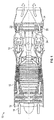
- FIG. 1 is a schematic illustration of a gas turbine engine 10.
- the gas turbine engine generally has a fan 12 through which ambient air is propelled in the direction of arrow 14, a compressor 16 for pressurizing the air received from the fan 12 and a combustor 18 wherein the compressed air is mixed with fuel and ignited for generating combustion gases.
- the gas turbine engine 10 further comprises a turbine section 20 for extracting energy from the combustion gases. Fuel is injected into the combustor 18 of the gas turbine engine 10 for mixing with the compressed air from the compressor 16 and ignition of the resultant mixture.
- the fan 12, compressor 16, combustor 18, and turbine 20 are typically all concentric about a common central longitudinal axis of the gas turbine engine 10.
- the gas turbine engine 10 may further comprise a low pressure compressor located upstream of a high pressure compressor and a high pressure turbine located upstream of a low pressure turbine.
- the compressor 16 may be a multi-stage compressor 16 that has a low-pressure compressor and a high-pressure compressor and the turbine 20 may be a multistage turbine 20 that has a high-pressure turbine and a low-pressure turbine.
- the low-pressure compressor is connected to the low-pressure turbine and the high pressure compressor is connected to the high-pressure turbine.
- the turbine 20 includes one or more sets, or stages, of fixed turbine vanes 22 and turbine rotors 24, each turbine rotor 24 including a plurality of turbine blades 26 (shown in FIG. 2 ).
- the turbine vanes 22 and the turbine blades 26 utilize a cooling airflow to maintain the turbine components within a desired temperature range.
- the cooling airflow may flow internal through the turbine components to cool the components internally, while in other embodiments, the cooling airflow is utilized to form a cooling film on exterior surfaces of the components.
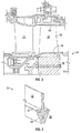
- FIG. 2 illustrates an example of a turbine rotor 24 structure in more detail. While the present description regards a turbine rotor 24 and turbine blades 26, it is to be appreciated that the present disclosure may be readily adapted to turbine vanes 22 and compressor 16 components.
- the turbine rotor 24 includes a turbine disc 28 having a disc rim 30 to which a plurality of radially-extending turbine blades 26 are mounted.
- Each turbine blade 26 includes an airfoil portion 32 extending from a blade platform 34.
- a blade root 36 extends radially inboard of the blade platform 34 and is inserted into a complimentary slot 38 or other opening in the disc rim 30 to mount the turbine blade 26 to the turbine disc 28.
- the turbine blade 26 may be anchored in place in the turbine disc 28 by bolts, rivets, or other mechanical fastening arrangements.
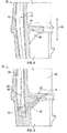
- FIG. 4 shown is a cross-sectional view of a turbine blade 26.
- the turbine blade 26 includes a pressure side 40 and a suction side 42, with a blade cavity 44 located between the pressure side 40 and the suction side 42 and extending along a spanwise direction 46 of the turbine blade 26 from the blade platform 34 toward a blade tip (shown in FIG. 2 ).
- a gusset 48 extends from the blade platform 34 toward the turbine blade 26, in some embodiments at the pressure side 40 of the turbine blade 26 and at a radially inboard side 50 of the blade platform 34. In some embodiments, the gusset 48 is located at about midchord of the turbine blade 26.
- the gusset 48 supports the blade platform 34 and reacts centrifugal loading on the blade platform 34, and further reduces bending stresses at the blade platform 34. It is to be appreciated that while shown at an approximately mid-chord location, the gusset 48 may be positioned at other selected locations along the turbine blade 26.
- the blade platform 34 includes a platform air passage 52, which is connected to the blade cavity 44 via a gusset air passage 54 extending through the gusset 48.
- the gusset air passage 54 allows for diversion of a portion of blade cooling airflow 56 from the blade cavity 44 to the platform air passage 52 to cool the blade platform 34 via, in some embodiments, a plurality of platform openings (not shown) in the blade platform forming a cooling film on the platform 34.
- the platform air passage 52 and the gusset air passage 54 may be formed concurrently with the manufacture of the turbine blade 26 by, for example, a casting process.
- the gusset air passage 54 is formed in a secondary process after formation of the turbine blade 26.
- the gusset air passage 54 may be formed by a drilling operation, after which an entry opening 56 at the turbine blade 26 is closed via, for example, welding.
- turbine vanes 22 may utilize gusset air passages 54 to cool platforms of turbine vanes 22.
- a single gusset 48 and gusset air passage 54 are shown, embodiments of turbine blades 26 or turbine vanes 22 may include two or more gussets 48 and/or two or more gusset air passages 54.
- the gusset air passage 54 is circular in cross-section, while in other embodiments, other cross-sectional shapes such as elliptical or oval, may be utilized.
- the platform air passage 52 may take one of a variety of shapes.
- the platform air passage 52 is configured to direct the cooling flow 56 into a platform air passage entrance 58 and then in an axially upstream direction 60, relative to a general airflow direction through the turbine section 20 toward a platform leading edge 62.
- the cooling airflow 56 then flows axially rearwardly toward a platform trailing edge 64 before exiting the platform air passage 52 at a platform air passage exit 66.
- the platform air passage 52 has a spiral shape.
- the gusset 48 and gusset air passage 54 may be located at or near a platform leading edge 62, with the cooling airflow 56 directed rearwardly along the platform air passage 52.
Abstract
Description
- This disclosure relates to gas turbine engines, and more particularly to thermal management of turbine components of gas turbine engines.
- Gas turbines hot section components, in particular turbine vanes and blades in the turbine section of the gas turbine are configured for use within particular temperature ranges. Such components often rely on cooling airflow to maintain turbine components within this particular temperature range. For example, stationary turbine vanes often have internal passages for cooling airflow to flow through, and additionally may have openings in an outer surface of the vane for cooling airflow to exit the interior of the vane structure and form a cooling film of air over the outer surface to provide the necessary thermal conditioning. Other components of the turbine often also require such thermal conditioning to reduce thermal gradients that would otherwise be present in the structure and which are generally undesirable. Thus, ways to increase thermal conditioning capability in the turbine are desired.
- In one embodiment, a blade assembly for a gas turbine engine includes a blade and a blade platform secured to the blade. The blade extends radially outwardly from the blade platform. The blade platform includes at least one platform airflow passage located therein. A gusset extends from the blade to the blade platform. The gusset includes a gusset airflow passage fluidly connected to the platform airflow passage to convey an airflow to the platform airflow passage.
- Additionally or alternatively, in this or other embodiments a blade airflow passage is positioned at the blade, the gusset airflow passage connecting the blade airflow passage to the platform airflow passage.
- Additionally or alternatively, in this or other embodiments the platform airflow passage is configured to convey the airflow toward a leading edge of the blade platform from a platform airflow passage entrance.
- Additionally or alternatively, in this or other embodiments the gusset is located at about midchord of the blade.
- Additionally or alternatively, in this or other embodiments the gusset is located at a pressure side of the blade.
- Additionally or alternatively, in this or other embodiments the gusset airflow passage is formed integral with the platform airflow passage.
- Additionally or alternatively, in this or other embodiments the gusset airflow passage is formed by casting.
- In another embodiment, a rotor assembly for a gas turbine engine includes a rotor disc and a plurality of rotor blades extending radially outwardly from the rotor disc. Each rotor blade includes a blade and a blade platform secured to the blade. The blade extends radially outwardly from the blade platform. The blade platform includes at least one platform airflow passage located therein. A gusset extends from the blade to the blade platform. The gusset includes a gusset airflow passage fluidly connected to the platform airflow passage to convey an airflow to the platform airflow passage.
- Additionally or alternatively, in this or other embodiments a blade airflow passage is located at the blade. The gusset airflow passage connects the blade airflow passage to the platform airflow passage.
- Additionally or alternatively, in this or other embodiments the platform airflow passage is configured to convey the airflow toward a leading edge of the blade platform from a platform airflow passage entrance.
- Additionally or alternatively, in this or other embodiments the gusset is located at about midchord of the blade.
- Additionally or alternatively, in this or other embodiments the gusset is located at a pressure side of the blade.
- Additionally or alternatively, in this or other embodiments the gusset airflow passage is formed integral with the platform airflow passage.
- Additionally or alternatively, in this or other embodiments the rotor assembly is a turbine rotor assembly.
- In yet another embodiment, a gas turbine engine includes a combustor and a plurality of gas turbine engine components located in fluid communication with the combustor. The gas turbine engine component includes an airfoil portion and a platform secured to the airfoil portion. The platform includes at least one platform airflow passage positioned therein. A gusset extends from the airfoil portion to the platform. The gusset includes a gusset airflow passage fluidly connected to the platform airflow passage to convey an airflow to the platform airflow passage.
- Additionally or alternatively, in this or other embodiments an airflow passage is located at the airfoil portion, the gusset airflow passage connecting the airfoil portion airflow passage to the platform airflow passage.
- Additionally or alternatively, in this or other embodiments the platform airflow passage is configured to convey the airflow toward a leading edge of the platform from a platform airflow passage entrance.
- Additionally or alternatively, in this or other embodiments the gusset is located at about midchord of the airfoil portion.
- Additionally or alternatively, in this or other embodiments the gusset is located at a pressure side of the airfoil portion.
- Additionally or alternatively, in this or other embodiments the gusset airflow passage is formed integral with the platform airflow passage.
- The subject matter which is regarded as the present disclosure is particularly pointed out and distinctly claimed in the claims at the conclusion of the specification. The foregoing and other features, and advantages of the present disclosure are apparent from the following detailed description taken in conjunction with the accompanying drawings in which:
-
FIG. 1 is a schematic illustration of a gas turbine engine; -
FIG. 2 is a schematic illustration of an embodiment of a turbine rotor assembly; -
FIG. 3 is another illustration of an embodiment of a turbine rotor assembly; -
FIG. 4 is a cross-sectional view of an embodiment of a turbine blade; -
FIG. 5 is another cross-sectional view of an embodiment of a turbine blade; -
FIG. 6 is a cross-sectional view of another embodiment of a turbine blade; and -
FIG. 7 is a partial perspective view of an embodiment of a turbine blade. -
FIG. 1 is a schematic illustration of agas turbine engine 10. The gas turbine engine generally has a fan 12 through which ambient air is propelled in the direction of arrow 14, acompressor 16 for pressurizing the air received from the fan 12 and acombustor 18 wherein the compressed air is mixed with fuel and ignited for generating combustion gases. - The
gas turbine engine 10 further comprises aturbine section 20 for extracting energy from the combustion gases. Fuel is injected into thecombustor 18 of thegas turbine engine 10 for mixing with the compressed air from thecompressor 16 and ignition of the resultant mixture. The fan 12,compressor 16,combustor 18, andturbine 20 are typically all concentric about a common central longitudinal axis of thegas turbine engine 10. - The
gas turbine engine 10 may further comprise a low pressure compressor located upstream of a high pressure compressor and a high pressure turbine located upstream of a low pressure turbine. For example, thecompressor 16 may be amulti-stage compressor 16 that has a low-pressure compressor and a high-pressure compressor and theturbine 20 may be amultistage turbine 20 that has a high-pressure turbine and a low-pressure turbine. In one embodiment, the low-pressure compressor is connected to the low-pressure turbine and the high pressure compressor is connected to the high-pressure turbine. - The
turbine 20 includes one or more sets, or stages, offixed turbine vanes 22 andturbine rotors 24, eachturbine rotor 24 including a plurality of turbine blades 26 (shown inFIG. 2 ). The turbine vanes 22 and theturbine blades 26 utilize a cooling airflow to maintain the turbine components within a desired temperature range. In some embodiments, the cooling airflow may flow internal through the turbine components to cool the components internally, while in other embodiments, the cooling airflow is utilized to form a cooling film on exterior surfaces of the components. -
FIG. 2 illustrates an example of aturbine rotor 24 structure in more detail. While the present description regards aturbine rotor 24 andturbine blades 26, it is to be appreciated that the present disclosure may be readily adapted toturbine vanes 22 andcompressor 16 components. Theturbine rotor 24 includes a turbine disc 28 having adisc rim 30 to which a plurality of radially-extendingturbine blades 26 are mounted. Eachturbine blade 26 includes anairfoil portion 32 extending from ablade platform 34. As shown inFIG. 3 , ablade root 36 extends radially inboard of theblade platform 34 and is inserted into acomplimentary slot 38 or other opening in thedisc rim 30 to mount theturbine blade 26 to the turbine disc 28. Theturbine blade 26 may be anchored in place in the turbine disc 28 by bolts, rivets, or other mechanical fastening arrangements. - Referring now to
FIG. 4 , shown is a cross-sectional view of aturbine blade 26. Theturbine blade 26 includes apressure side 40 and asuction side 42, with ablade cavity 44 located between thepressure side 40 and thesuction side 42 and extending along aspanwise direction 46 of theturbine blade 26 from theblade platform 34 toward a blade tip (shown inFIG. 2 ). Agusset 48 extends from theblade platform 34 toward theturbine blade 26, in some embodiments at thepressure side 40 of theturbine blade 26 and at a radiallyinboard side 50 of theblade platform 34. In some embodiments, thegusset 48 is located at about midchord of theturbine blade 26. Thegusset 48 supports theblade platform 34 and reacts centrifugal loading on theblade platform 34, and further reduces bending stresses at theblade platform 34. It is to be appreciated that while shown at an approximately mid-chord location, thegusset 48 may be positioned at other selected locations along theturbine blade 26. - Referring now to
FIG. 5 , a cross-sectional view of theturbine blade 26 through thegusset 48 is illustrated. Theblade platform 34 includes aplatform air passage 52, which is connected to theblade cavity 44 via agusset air passage 54 extending through thegusset 48. Thegusset air passage 54 allows for diversion of a portion ofblade cooling airflow 56 from theblade cavity 44 to theplatform air passage 52 to cool theblade platform 34 via, in some embodiments, a plurality of platform openings (not shown) in the blade platform forming a cooling film on theplatform 34. In the embodiment ofFIG. 5 , theplatform air passage 52 and thegusset air passage 54 may be formed concurrently with the manufacture of theturbine blade 26 by, for example, a casting process. In an alternative embodiment, illustrated inFIG. 6 , thegusset air passage 54 is formed in a secondary process after formation of theturbine blade 26. For example, thegusset air passage 54 may be formed by a drilling operation, after which anentry opening 56 at theturbine blade 26 is closed via, for example, welding. It is to be appreciated that while thegusset air passage 54 is described herein as being located at theturbine blade 26,turbine vanes 22 may utilizegusset air passages 54 to cool platforms ofturbine vanes 22. Further, while asingle gusset 48 andgusset air passage 54 are shown, embodiments ofturbine blades 26 orturbine vanes 22 may include two ormore gussets 48 and/or two or moregusset air passages 54. In some embodiments, thegusset air passage 54 is circular in cross-section, while in other embodiments, other cross-sectional shapes such as elliptical or oval, may be utilized. - Referring now to
FIG. 7 , theplatform air passage 52 may take one of a variety of shapes. In one embodiment, as shown, theplatform air passage 52 is configured to direct thecooling flow 56 into a platformair passage entrance 58 and then in an axiallyupstream direction 60, relative to a general airflow direction through theturbine section 20 toward aplatform leading edge 62. The coolingairflow 56 then flows axially rearwardly toward aplatform trailing edge 64 before exiting theplatform air passage 52 at a platformair passage exit 66. In some embodiments, theplatform air passage 52 has a spiral shape. Directing the coolingairflow 56 forward, then rearwardly, directs the highestpressure cooling airflow 56 at theplatform leading edge 62, prior to pressure losses degrading the cooling effectiveness of the airflow as it flows rearwardly. In alternative embodiments, thegusset 48 andgusset air passage 54 may be located at or near aplatform leading edge 62, with the coolingairflow 56 directed rearwardly along theplatform air passage 52. - While the present disclosure has been described in detail in connection with only a limited number of embodiments, it should be readily understood that the present disclosure is not limited to such disclosed embodiments. Rather, the present disclosure can be modified to incorporate any number of variations, alterations, substitutions or equivalent arrangements not heretofore described, but which are commensurate with the spirit and scope of the present disclosure. Additionally, while various embodiments of the present disclosure have been described, it is to be understood that aspects of the present disclosure may include only some of the described embodiments. Accordingly, the present disclosure is not to be seen as limited by the foregoing description, but is only limited by the scope of the appended claims.
Claims (15)
- A blade assembly for a gas turbine engine, comprising:a blade;a blade platform secured to the blade, the blade extending radially outwardly from the blade platform, the blade platform including at least one platform airflow passage disposed therein; anda gusset extending from the blade to the blade platform, the gusset including a gusset airflow passage fluidly connected to the platform airflow passage to convey an airflow to the platform airflow passage.
- The blade assembly of claim 1, further comprising a blade airflow passage disposed at the blade, the gusset airflow passage connecting the blade airflow passage to the platform airflow passage.
- The blade assembly of claim 1 or claim 2, wherein the platform airflow passage is configured to convey the airflow toward a leading edge of the blade platform from a platform airflow passage entrance.
- The blade assembly of any preceding claim, wherein the gusset is disposed at about midchord of the blade.
- The blade assembly of any preceding claim, wherein the gusset is disposed at a pressure side of the blade.
- The blade assembly of any preceding claim, wherein the gusset airflow passage is formed integral with the platform airflow passage.
- The blade assembly of claim 6, wherein the gusset airflow passage is formed by casting.
- A rotor assembly for a gas'turbine engine, comprising:a rotor disc; anda plurality of rotor blades extending radially outwardly from the rotor disc, each rotor blade being a blade assembly as claimed in any preceding claim.
- The rotor assembly of claim 8, wherein rotor assembly is a turbine rotor assembly.
- A gas turbine engine, comprising:a combustor; anda plurality of gas turbine engine components disposed in fluid communication with the combustor, including:an airfoil portion;a platform secured to the airfoil portion, the platform including at least one platform airflow passage disposed therein; anda gusset extending from the airfoil portion to the platform, the gusset including a gusset airflow passage fluidly connected to the platform airflow passage to convey an airflow to the platform airflow passage.
- The gas turbine engine of claim 10, further comprising an airflow passage disposed at the airfoil portion, the gusset airflow passage connecting the airfoil portion airflow passage to the platform airflow passage.
- The gas turbine engine of claim 10 or claim 11, wherein the platform airflow passage is configured to convey the airflow toward a leading edge of the platform from a platform airflow passage entrance.
- The gas turbine engine of any of claims 10 to 12, wherein the gusset is disposed at about midchord of the airfoil portion.
- The gas turbine engine of any of claims 10 to 13, wherein the gusset is disposed at a pressure side of the airfoil portion.
- The gas turbine engine of any of claims 10 to 14, wherein the gusset airflow passage is formed integral with the platform airflow passage.
Applications Claiming Priority (1)
| Application Number | Priority Date | Filing Date | Title |
|---|---|---|---|
| US14/886,201 US10677070B2 (en) | 2015-10-19 | 2015-10-19 | Blade platform gusset with internal cooling |
Publications (2)
| Publication Number | Publication Date |
|---|---|
| EP3159482A1 true EP3159482A1 (en) | 2017-04-26 |
| EP3159482B1 EP3159482B1 (en) | 2022-03-30 |
Family
ID=57137950
Family Applications (1)
| Application Number | Title | Priority Date | Filing Date |
|---|---|---|---|
| EP16194110.9A Active EP3159482B1 (en) | 2015-10-19 | 2016-10-17 | Blade assembly , corresponding rotor assembly and gas turbine engine |
Country Status (2)
| Country | Link |
|---|---|
| US (1) | US10677070B2 (en) |
| EP (1) | EP3159482B1 (en) |
Citations (3)
| Publication number | Priority date | Publication date | Assignee | Title |
|---|---|---|---|---|
| US20060093484A1 (en) * | 2004-11-04 | 2006-05-04 | Siemens Westinghouse Power Corp. | Cooling system for a platform of a turbine blade |
| EP2037081A1 (en) * | 2007-02-21 | 2009-03-18 | Mitsubishi Heavy Industries, Ltd. | Platform cooling structure of gas turbine rotor blade |
| EP2228518A2 (en) * | 2009-03-10 | 2010-09-15 | Honeywell International Inc. | Cooled turbine blade platform |
Family Cites Families (6)
| Publication number | Priority date | Publication date | Assignee | Title |
|---|---|---|---|---|
| US6158962A (en) * | 1999-04-30 | 2000-12-12 | General Electric Company | Turbine blade with ribbed platform |
| US7467922B2 (en) * | 2005-07-25 | 2008-12-23 | Siemens Aktiengesellschaft | Cooled turbine blade or vane for a gas turbine, and use of a turbine blade or vane of this type |
| US7695246B2 (en) * | 2006-01-31 | 2010-04-13 | United Technologies Corporation | Microcircuits for small engines |
| US7416391B2 (en) * | 2006-02-24 | 2008-08-26 | General Electric Company | Bucket platform cooling circuit and method |
| US8734111B2 (en) * | 2011-06-27 | 2014-05-27 | General Electric Company | Platform cooling passages and methods for creating platform cooling passages in turbine rotor blades |
| US8961134B2 (en) * | 2011-06-29 | 2015-02-24 | Siemens Energy, Inc. | Turbine blade or vane with separate endwall |
-
2015
- 2015-10-19 US US14/886,201 patent/US10677070B2/en active Active
-
2016
- 2016-10-17 EP EP16194110.9A patent/EP3159482B1/en active Active
Patent Citations (3)
| Publication number | Priority date | Publication date | Assignee | Title |
|---|---|---|---|---|
| US20060093484A1 (en) * | 2004-11-04 | 2006-05-04 | Siemens Westinghouse Power Corp. | Cooling system for a platform of a turbine blade |
| EP2037081A1 (en) * | 2007-02-21 | 2009-03-18 | Mitsubishi Heavy Industries, Ltd. | Platform cooling structure of gas turbine rotor blade |
| EP2228518A2 (en) * | 2009-03-10 | 2010-09-15 | Honeywell International Inc. | Cooled turbine blade platform |
Also Published As
| Publication number | Publication date |
|---|---|
| US20170107830A1 (en) | 2017-04-20 |
| EP3159482B1 (en) | 2022-03-30 |
| US10677070B2 (en) | 2020-06-09 |
Similar Documents
| Publication | Publication Date | Title |
|---|---|---|
| US10822957B2 (en) | Fillet optimization for turbine airfoil | |
| CN107448300B (en) | Airfoil for a turbine engine | |
| CN106545365B (en) | Nozzle segment, nozzle assembly and gas turbine engine | |
| CN106988789B (en) | Engine component with film cooling | |
| EP1693552A2 (en) | A turbine blade | |
| CN106801624B (en) | Turbine blade | |
| US10815789B2 (en) | Impingement holes for a turbine engine component | |
| US20060127212A1 (en) | Airfoil platform impingement cooling | |
| US11208901B2 (en) | Trailing edge cooling for a turbine blade | |
| EP2930371A1 (en) | Radial impeller with a bleeding port | |
| JP2017078414A (en) | Turbine blade | |
| US8235652B2 (en) | Turbine nozzle segment | |
| US20170159449A1 (en) | Gas turbine engine with fillet film holes | |
| JP2019007478A (en) | Rotor blade tip | |
| CN107084006B (en) | Accelerator insert for a gas turbine engine airfoil | |
| CN107091122B (en) | Turbine engine airfoil with cooling | |
| US20170226868A1 (en) | Gas turbine engine airfoil | |
| EP2867479B1 (en) | Component for a gas turbine engine and corresponding gas turbine engine | |
| EP3130751B1 (en) | Apparatus and method for cooling the rotor of a gas turbine | |
| EP3159482B1 (en) | Blade assembly , corresponding rotor assembly and gas turbine engine | |
| US10808572B2 (en) | Cooling structure for a turbomachinery component | |
| US10612389B2 (en) | Engine component with porous section | |
| EP3133244A1 (en) | Film cooling passage |
Legal Events
| Date | Code | Title | Description |
|---|---|---|---|
| PUAI | Public reference made under article 153(3) epc to a published international application that has entered the european phase |
Free format text: ORIGINAL CODE: 0009012 |
|
| STAA | Information on the status of an ep patent application or granted ep patent |
Free format text: STATUS: THE APPLICATION HAS BEEN PUBLISHED |
|
| AK | Designated contracting states |
Kind code of ref document: A1 Designated state(s): AL AT BE BG CH CY CZ DE DK EE ES FI FR GB GR HR HU IE IS IT LI LT LU LV MC MK MT NL NO PL PT RO RS SE SI SK SM TR |
|
| AX | Request for extension of the european patent |
Extension state: BA ME |
|
| STAA | Information on the status of an ep patent application or granted ep patent |
Free format text: STATUS: REQUEST FOR EXAMINATION WAS MADE |
|
| 17P | Request for examination filed |
Effective date: 20171026 |
|
| RBV | Designated contracting states (corrected) |
Designated state(s): AL AT BE BG CH CY CZ DE DK EE ES FI FR GB GR HR HU IE IS IT LI LT LU LV MC MK MT NL NO PL PT RO RS SE SI SK SM TR |
|
| STAA | Information on the status of an ep patent application or granted ep patent |
Free format text: STATUS: EXAMINATION IS IN PROGRESS |
|
| STAA | Information on the status of an ep patent application or granted ep patent |
Free format text: STATUS: EXAMINATION IS IN PROGRESS |
|
| 17Q | First examination report despatched |
Effective date: 20201020 |
|
| RAP1 | Party data changed (applicant data changed or rights of an application transferred) |
Owner name: RAYTHEON TECHNOLOGIES CORPORATION |
|
| GRAP | Despatch of communication of intention to grant a patent |
Free format text: ORIGINAL CODE: EPIDOSNIGR1 |
|
| STAA | Information on the status of an ep patent application or granted ep patent |
Free format text: STATUS: GRANT OF PATENT IS INTENDED |
|
| INTG | Intention to grant announced |
Effective date: 20211011 |
|
| GRAS | Grant fee paid |
Free format text: ORIGINAL CODE: EPIDOSNIGR3 |
|
| GRAA | (expected) grant |
Free format text: ORIGINAL CODE: 0009210 |
|
| STAA | Information on the status of an ep patent application or granted ep patent |
Free format text: STATUS: THE PATENT HAS BEEN GRANTED |
|
| AK | Designated contracting states |
Kind code of ref document: B1 Designated state(s): AL AT BE BG CH CY CZ DE DK EE ES FI FR GB GR HR HU IE IS IT LI LT LU LV MC MK MT NL NO PL PT RO RS SE SI SK SM TR |
|
| REG | Reference to a national code |
Ref country code: GB Ref legal event code: FG4D |
|
| REG | Reference to a national code |
Ref country code: CH Ref legal event code: EP |
|
| REG | Reference to a national code |
Ref country code: AT Ref legal event code: REF Ref document number: 1479363 Country of ref document: AT Kind code of ref document: T Effective date: 20220415 |
|
| REG | Reference to a national code |
Ref country code: DE Ref legal event code: R096 Ref document number: 602016070440 Country of ref document: DE |
|
| REG | Reference to a national code |
Ref country code: IE Ref legal event code: FG4D |
|
| REG | Reference to a national code |
Ref country code: LT Ref legal event code: MG9D |
|
| PG25 | Lapsed in a contracting state [announced via postgrant information from national office to epo] |
Ref country code: SE Free format text: LAPSE BECAUSE OF FAILURE TO SUBMIT A TRANSLATION OF THE DESCRIPTION OR TO PAY THE FEE WITHIN THE PRESCRIBED TIME-LIMIT Effective date: 20220330 Ref country code: RS Free format text: LAPSE BECAUSE OF FAILURE TO SUBMIT A TRANSLATION OF THE DESCRIPTION OR TO PAY THE FEE WITHIN THE PRESCRIBED TIME-LIMIT Effective date: 20220330 Ref country code: NO Free format text: LAPSE BECAUSE OF FAILURE TO SUBMIT A TRANSLATION OF THE DESCRIPTION OR TO PAY THE FEE WITHIN THE PRESCRIBED TIME-LIMIT Effective date: 20220630 Ref country code: LT Free format text: LAPSE BECAUSE OF FAILURE TO SUBMIT A TRANSLATION OF THE DESCRIPTION OR TO PAY THE FEE WITHIN THE PRESCRIBED TIME-LIMIT Effective date: 20220330 Ref country code: HR Free format text: LAPSE BECAUSE OF FAILURE TO SUBMIT A TRANSLATION OF THE DESCRIPTION OR TO PAY THE FEE WITHIN THE PRESCRIBED TIME-LIMIT Effective date: 20220330 Ref country code: BG Free format text: LAPSE BECAUSE OF FAILURE TO SUBMIT A TRANSLATION OF THE DESCRIPTION OR TO PAY THE FEE WITHIN THE PRESCRIBED TIME-LIMIT Effective date: 20220630 |
|
| REG | Reference to a national code |
Ref country code: NL Ref legal event code: MP Effective date: 20220330 |
|
| REG | Reference to a national code |
Ref country code: AT Ref legal event code: MK05 Ref document number: 1479363 Country of ref document: AT Kind code of ref document: T Effective date: 20220330 |
|
| PG25 | Lapsed in a contracting state [announced via postgrant information from national office to epo] |
Ref country code: LV Free format text: LAPSE BECAUSE OF FAILURE TO SUBMIT A TRANSLATION OF THE DESCRIPTION OR TO PAY THE FEE WITHIN THE PRESCRIBED TIME-LIMIT Effective date: 20220330 Ref country code: GR Free format text: LAPSE BECAUSE OF FAILURE TO SUBMIT A TRANSLATION OF THE DESCRIPTION OR TO PAY THE FEE WITHIN THE PRESCRIBED TIME-LIMIT Effective date: 20220701 Ref country code: FI Free format text: LAPSE BECAUSE OF FAILURE TO SUBMIT A TRANSLATION OF THE DESCRIPTION OR TO PAY THE FEE WITHIN THE PRESCRIBED TIME-LIMIT Effective date: 20220330 |
|
| PG25 | Lapsed in a contracting state [announced via postgrant information from national office to epo] |
Ref country code: NL Free format text: LAPSE BECAUSE OF FAILURE TO SUBMIT A TRANSLATION OF THE DESCRIPTION OR TO PAY THE FEE WITHIN THE PRESCRIBED TIME-LIMIT Effective date: 20220330 |
|
| PG25 | Lapsed in a contracting state [announced via postgrant information from national office to epo] |
Ref country code: SM Free format text: LAPSE BECAUSE OF FAILURE TO SUBMIT A TRANSLATION OF THE DESCRIPTION OR TO PAY THE FEE WITHIN THE PRESCRIBED TIME-LIMIT Effective date: 20220330 Ref country code: SK Free format text: LAPSE BECAUSE OF FAILURE TO SUBMIT A TRANSLATION OF THE DESCRIPTION OR TO PAY THE FEE WITHIN THE PRESCRIBED TIME-LIMIT Effective date: 20220330 Ref country code: RO Free format text: LAPSE BECAUSE OF FAILURE TO SUBMIT A TRANSLATION OF THE DESCRIPTION OR TO PAY THE FEE WITHIN THE PRESCRIBED TIME-LIMIT Effective date: 20220330 Ref country code: PT Free format text: LAPSE BECAUSE OF FAILURE TO SUBMIT A TRANSLATION OF THE DESCRIPTION OR TO PAY THE FEE WITHIN THE PRESCRIBED TIME-LIMIT Effective date: 20220801 Ref country code: ES Free format text: LAPSE BECAUSE OF FAILURE TO SUBMIT A TRANSLATION OF THE DESCRIPTION OR TO PAY THE FEE WITHIN THE PRESCRIBED TIME-LIMIT Effective date: 20220330 Ref country code: EE Free format text: LAPSE BECAUSE OF FAILURE TO SUBMIT A TRANSLATION OF THE DESCRIPTION OR TO PAY THE FEE WITHIN THE PRESCRIBED TIME-LIMIT Effective date: 20220330 Ref country code: CZ Free format text: LAPSE BECAUSE OF FAILURE TO SUBMIT A TRANSLATION OF THE DESCRIPTION OR TO PAY THE FEE WITHIN THE PRESCRIBED TIME-LIMIT Effective date: 20220330 Ref country code: AT Free format text: LAPSE BECAUSE OF FAILURE TO SUBMIT A TRANSLATION OF THE DESCRIPTION OR TO PAY THE FEE WITHIN THE PRESCRIBED TIME-LIMIT Effective date: 20220330 |
|
| PG25 | Lapsed in a contracting state [announced via postgrant information from national office to epo] |
Ref country code: PL Free format text: LAPSE BECAUSE OF FAILURE TO SUBMIT A TRANSLATION OF THE DESCRIPTION OR TO PAY THE FEE WITHIN THE PRESCRIBED TIME-LIMIT Effective date: 20220330 Ref country code: IS Free format text: LAPSE BECAUSE OF FAILURE TO SUBMIT A TRANSLATION OF THE DESCRIPTION OR TO PAY THE FEE WITHIN THE PRESCRIBED TIME-LIMIT Effective date: 20220730 Ref country code: AL Free format text: LAPSE BECAUSE OF FAILURE TO SUBMIT A TRANSLATION OF THE DESCRIPTION OR TO PAY THE FEE WITHIN THE PRESCRIBED TIME-LIMIT Effective date: 20220330 |
|
| REG | Reference to a national code |
Ref country code: DE Ref legal event code: R097 Ref document number: 602016070440 Country of ref document: DE |
|
| PG25 | Lapsed in a contracting state [announced via postgrant information from national office to epo] |
Ref country code: DK Free format text: LAPSE BECAUSE OF FAILURE TO SUBMIT A TRANSLATION OF THE DESCRIPTION OR TO PAY THE FEE WITHIN THE PRESCRIBED TIME-LIMIT Effective date: 20220330 |
|
| PLBE | No opposition filed within time limit |
Free format text: ORIGINAL CODE: 0009261 |
|
| STAA | Information on the status of an ep patent application or granted ep patent |
Free format text: STATUS: NO OPPOSITION FILED WITHIN TIME LIMIT |
|
| 26N | No opposition filed |
Effective date: 20230103 |
|
| PG25 | Lapsed in a contracting state [announced via postgrant information from national office to epo] |
Ref country code: SI Free format text: LAPSE BECAUSE OF FAILURE TO SUBMIT A TRANSLATION OF THE DESCRIPTION OR TO PAY THE FEE WITHIN THE PRESCRIBED TIME-LIMIT Effective date: 20220330 Ref country code: MC Free format text: LAPSE BECAUSE OF FAILURE TO SUBMIT A TRANSLATION OF THE DESCRIPTION OR TO PAY THE FEE WITHIN THE PRESCRIBED TIME-LIMIT Effective date: 20220330 |
|
| REG | Reference to a national code |
Ref country code: CH Ref legal event code: PL |
|
| REG | Reference to a national code |
Ref country code: BE Ref legal event code: MM Effective date: 20221031 |
|
| P01 | Opt-out of the competence of the unified patent court (upc) registered |
Effective date: 20230520 |
|
| PG25 | Lapsed in a contracting state [announced via postgrant information from national office to epo] |
Ref country code: LU Free format text: LAPSE BECAUSE OF NON-PAYMENT OF DUE FEES Effective date: 20221017 |
|
| PG25 | Lapsed in a contracting state [announced via postgrant information from national office to epo] |
Ref country code: LI Free format text: LAPSE BECAUSE OF NON-PAYMENT OF DUE FEES Effective date: 20221031 Ref country code: IT Free format text: LAPSE BECAUSE OF FAILURE TO SUBMIT A TRANSLATION OF THE DESCRIPTION OR TO PAY THE FEE WITHIN THE PRESCRIBED TIME-LIMIT Effective date: 20220330 Ref country code: CH Free format text: LAPSE BECAUSE OF NON-PAYMENT OF DUE FEES Effective date: 20221031 |
|
| PG25 | Lapsed in a contracting state [announced via postgrant information from national office to epo] |
Ref country code: BE Free format text: LAPSE BECAUSE OF NON-PAYMENT OF DUE FEES Effective date: 20221031 |
|
| PG25 | Lapsed in a contracting state [announced via postgrant information from national office to epo] |
Ref country code: IE Free format text: LAPSE BECAUSE OF NON-PAYMENT OF DUE FEES Effective date: 20221017 |
|
| PGFP | Annual fee paid to national office [announced via postgrant information from national office to epo] |
Ref country code: GB Payment date: 20230920 Year of fee payment: 8 |
|
| PGFP | Annual fee paid to national office [announced via postgrant information from national office to epo] |
Ref country code: FR Payment date: 20230920 Year of fee payment: 8 |
|
| PGFP | Annual fee paid to national office [announced via postgrant information from national office to epo] |
Ref country code: DE Payment date: 20230920 Year of fee payment: 8 |
|
| PG25 | Lapsed in a contracting state [announced via postgrant information from national office to epo] |
Ref country code: HU Free format text: LAPSE BECAUSE OF FAILURE TO SUBMIT A TRANSLATION OF THE DESCRIPTION OR TO PAY THE FEE WITHIN THE PRESCRIBED TIME-LIMIT; INVALID AB INITIO Effective date: 20161017 |