EP3184409A2 - Vehicle - Google Patents
Vehicle Download PDFInfo
- Publication number
- EP3184409A2 EP3184409A2 EP16200204.2A EP16200204A EP3184409A2 EP 3184409 A2 EP3184409 A2 EP 3184409A2 EP 16200204 A EP16200204 A EP 16200204A EP 3184409 A2 EP3184409 A2 EP 3184409A2
- Authority
- EP
- European Patent Office
- Prior art keywords
- body frame
- vehicle
- foot placement
- front wheel
- cross member
- Prior art date
- Legal status (The legal status is an assumption and is not a legal conclusion. Google has not performed a legal analysis and makes no representation as to the accuracy of the status listed.)
- Granted
Links
Images





Classifications
-
- B—PERFORMING OPERATIONS; TRANSPORTING
- B62—LAND VEHICLES FOR TRAVELLING OTHERWISE THAN ON RAILS
- B62K—CYCLES; CYCLE FRAMES; CYCLE STEERING DEVICES; RIDER-OPERATED TERMINAL CONTROLS SPECIALLY ADAPTED FOR CYCLES; CYCLE AXLE SUSPENSIONS; CYCLE SIDECARS, FORECARS, OR THE LIKE
- B62K5/00—Cycles with handlebars, equipped with three or more main road wheels
- B62K5/10—Cycles with handlebars, equipped with three or more main road wheels with means for inwardly inclining the vehicle body on bends
-
- B—PERFORMING OPERATIONS; TRANSPORTING
- B62—LAND VEHICLES FOR TRAVELLING OTHERWISE THAN ON RAILS
- B62J—CYCLE SADDLES OR SEATS; AUXILIARY DEVICES OR ACCESSORIES SPECIALLY ADAPTED TO CYCLES AND NOT OTHERWISE PROVIDED FOR, e.g. ARTICLE CARRIERS OR CYCLE PROTECTORS
- B62J25/00—Foot-rests; Knee grips; Passenger hand-grips
- B62J25/04—Floor-type foot rests
-
- B—PERFORMING OPERATIONS; TRANSPORTING
- B62—LAND VEHICLES FOR TRAVELLING OTHERWISE THAN ON RAILS
- B62K—CYCLES; CYCLE FRAMES; CYCLE STEERING DEVICES; RIDER-OPERATED TERMINAL CONTROLS SPECIALLY ADAPTED FOR CYCLES; CYCLE AXLE SUSPENSIONS; CYCLE SIDECARS, FORECARS, OR THE LIKE
- B62K11/00—Motorcycles, engine-assisted cycles or motor scooters with one or two wheels
- B62K11/02—Frames
- B62K11/04—Frames characterised by the engine being between front and rear wheels
-
- B—PERFORMING OPERATIONS; TRANSPORTING
- B62—LAND VEHICLES FOR TRAVELLING OTHERWISE THAN ON RAILS
- B62K—CYCLES; CYCLE FRAMES; CYCLE STEERING DEVICES; RIDER-OPERATED TERMINAL CONTROLS SPECIALLY ADAPTED FOR CYCLES; CYCLE AXLE SUSPENSIONS; CYCLE SIDECARS, FORECARS, OR THE LIKE
- B62K3/00—Bicycles
- B62K3/002—Bicycles without a seat, i.e. the rider operating the vehicle in a standing position, e.g. non-motorized scooters; non-motorized scooters with skis or runners
-
- B—PERFORMING OPERATIONS; TRANSPORTING
- B62—LAND VEHICLES FOR TRAVELLING OTHERWISE THAN ON RAILS
- B62K—CYCLES; CYCLE FRAMES; CYCLE STEERING DEVICES; RIDER-OPERATED TERMINAL CONTROLS SPECIALLY ADAPTED FOR CYCLES; CYCLE AXLE SUSPENSIONS; CYCLE SIDECARS, FORECARS, OR THE LIKE
- B62K5/00—Cycles with handlebars, equipped with three or more main road wheels
- B62K5/02—Tricycles
- B62K5/027—Motorcycles with three wheels
-
- B—PERFORMING OPERATIONS; TRANSPORTING
- B62—LAND VEHICLES FOR TRAVELLING OTHERWISE THAN ON RAILS
- B62K—CYCLES; CYCLE FRAMES; CYCLE STEERING DEVICES; RIDER-OPERATED TERMINAL CONTROLS SPECIALLY ADAPTED FOR CYCLES; CYCLE AXLE SUSPENSIONS; CYCLE SIDECARS, FORECARS, OR THE LIKE
- B62K5/00—Cycles with handlebars, equipped with three or more main road wheels
- B62K5/02—Tricycles
- B62K5/05—Tricycles characterised by a single rear wheel
-
- B—PERFORMING OPERATIONS; TRANSPORTING
- B62—LAND VEHICLES FOR TRAVELLING OTHERWISE THAN ON RAILS
- B62K—CYCLES; CYCLE FRAMES; CYCLE STEERING DEVICES; RIDER-OPERATED TERMINAL CONTROLS SPECIALLY ADAPTED FOR CYCLES; CYCLE AXLE SUSPENSIONS; CYCLE SIDECARS, FORECARS, OR THE LIKE
- B62K5/00—Cycles with handlebars, equipped with three or more main road wheels
- B62K5/08—Cycles with handlebars, equipped with three or more main road wheels with steering devices acting on two or more wheels
-
- B—PERFORMING OPERATIONS; TRANSPORTING
- B62—LAND VEHICLES FOR TRAVELLING OTHERWISE THAN ON RAILS
- B62K—CYCLES; CYCLE FRAMES; CYCLE STEERING DEVICES; RIDER-OPERATED TERMINAL CONTROLS SPECIALLY ADAPTED FOR CYCLES; CYCLE AXLE SUSPENSIONS; CYCLE SIDECARS, FORECARS, OR THE LIKE
- B62K5/00—Cycles with handlebars, equipped with three or more main road wheels
- B62K2005/001—Suspension details for cycles with three or more main road wheels
Definitions
- the present disclosure relates to a vehicle equipped with a leanable body frame and two front wheels.
- a vehicle described in, for example, Patent Literature 1 comprises a body frame and two front wheels that are arranged side by side in a left-right direction of the body frame.
- the vehicle comprises a link mechanism.
- the link mechanism is disposed above the two front wheels.
- the link mechanism is configured so as to change positions of the two front wheels relative to the body frame to thereby cause the body frame to lean to the left or right of the vehicle.
- the vehicle described above comprises an anti-roll device in order to restrict the leaning of the body frame.
- a vehicle includes a body frame; a left front wheel and a right front wheel that are arranged side by side in a left-right direction of the body frame; a link mechanism disposed above the left front wheel and the right front wheel in an up-down direction of the body frame, and comprising an upper cross member, a lower cross member, a left side member and a right side member that are connected with each other such that the upper cross member and the lower cross member are configured to maintain their postures parallel to each other while the left side member and the right side member are configured to maintain their postures parallel to each other, thereby being configured to change positions of the left front wheel and the right front wheel relative to the body frame to cause the body frame to lean to left or right of the vehicle; a left front wheel supporting portion connected to the link mechanism and supporting the left front wheel; a right front wheel supporting portion connected to the link mechanism and supporting the right front wheel; and a load transmission mechanism comprising a left foot placement
- the "left portion” of a member represents a portion that is situated on the left of a center of that member in the left-right direction of the body frame.
- the "right portion” of a member represents a portion that is situated on the left of a center of that member in the left-right direction of the body frame.
- the leaning of the body frame can be controlled by individually controlling the load applied to the left foot placement face through the left foot of the rider and the load applied to the right foot placement face through the right foot of the rider.
- the left portion of the link mechanism including the left portion of the upper cross member, the left portion of the lower cross member and the left side member is displaced to a position above the right portion of the link mechanism including the right portion of the upper cross member, the right portion of the lower cross member and the right side member in the up-down direction of the body frame.
- a load is applied to the left portion of the link mechanism through the left foot placement face by the left foot of the rider, a force acts to displace the left portion of the link mechanism downwards, whereby the leaning of the body frame to the left of the vehicle can be suppressed.
- the leaning of the vehicle can be controlled without the necessity of providing a complicated mechanism such as an anti-rolling device described in Patent Literature 1.
- the leaning of the body frame of the vehicle equipped with the leanable body frame and the two front wheels can be controlled with the simpler configuration.
- the above vehicle may be configured so as to further comprise:
- the left foot placement face and the right foot placement face are provided in such portions that are not able to displace relative to the body frame in accordance with the motion of the steering force transmission mechanism, they are not displaced in the direction in which the steering member turns when the vehicle is operated to be steered.
- the left foot placement face and the right foot placement face are allowed to move only in the up-down direction of the body frame and in the directions in which the body frame is caused to lean. Consequently, in providing the mechanism which controls the leaning of the body frame, the enlargement in size of the vehicle can be suppressed.
- the above vehicle may be configured such that:
- a moving range of each of the left side member and the right side member in the left-right direction of the body frame when the vehicle is caused to lean is less than a moving range in the up-down direction of the body frame thereof. Consequently, the enlargement of the moving range of each of the left foot placement face and the right foot placement face when the vehicle is caused to lean can be suppressed particularly in the left-right direction of the body frame. This advantageous effect becomes remarkable particularly in a case where the left foot placement face and the right foot placement face are situated farther away from the turning center of the lower cross member.
- the above vehicle may be configured such that:
- vehicle may be configured such that:
- joind integrally to means that two members are not displaced relative to each other at a joined portion by welding, fastening, or the like.
- the configuration which can control the leaning of the body frame of the vehicle equipped with the leanable body frame and the two front wheels can be made simpler.
- the above vehicle may be configured such that:
- the left foot rest portion when the vehicle is caused to lean, the left foot rest portion turns relative to the upper cross member and the lower cross member while maintaining its posture which is substantially parallel to the left side member.
- the members are necessary which realize the turning operations, by disposing the upper left connecting member and the lower left connecting member on the right of the left side member in the left-right direction of the body frame, the enlargement of the moving range of the left foot placement face when the vehicle is caused to lean can be further suppressed.
- the right foot rest portion turns relative to the upper cross member and the lower cross member while maintaining its posture which is substantially parallel to a right side member.
- the members are necessary which realize the turning operations, by disposing the upper right connecting member and the lower right connecting member on the left of the right side member in the left-right direction of the body frame, the enlargement of the moving range of the right foot placement face when the vehicle is caused to lean can be further suppressed.
- the above vehicle may be configured such that:
- the rider easily places his or her left foot and right foot on the left foot placement face and the right foot placement face, respectively.
- the rider can mount and dismount from the vehicle easily as well as the rider can obtain a good operation feeling.
- the above vehicle may be configured such that:
- the interference of the left foot placement face with the left front wheel may be easily avoided, as well as the interference of the right foot placement face with the right front wheel may be also avoided easily.
- the vehicle may be configured so as to further comprise a rear wheel, wherein:
- the center of gravity of the body is situated relatively forwards.
- the center of gravity of the body is located further forwards.
- loads applied through the left foot and the right foot of the rider are difficult to be transmitted to the link mechanism. According to the configuration described above, not only the center of gravity of the vehicle in operation is allowed to be situated in a proper position but also the loads are allowed to be applied easily.
- the above vehicle may be configured so as to further comprise a driving power source disposed behind the link mechanism in the front-rear direction of the body frame, and configured to supply driving power of the vehicle, wherein:
- the left foot placement face and the right foot placement face should be disposed so as to be spaced away from each other in the left-right direction of the body frame.
- the above vehicle may be configured such that:
- the left shock absorbing mechanism is interposed between the left portion of the link mechanism where the left foot rest portion is provided and the left front wheel, it is possible to reduce the transmission of vibration from the left front wheel to the left foot placement face.
- the right shock absorbing mechanism is interposed between the right portion of the link mechanism where the right foot placement face is provided and the right front wheel, it is possible to reduce the transmission of vibration from the right front wheel to the right foot placement face. Consequently, the comfort in riding the vehicle is enhanced.
- an arrow F denotes a front or forward direction of a vehicle.
- An arrow B denotes a back/rear or backward/rearward direction of the vehicle.
- An arrow U denotes an up or upward direction of the vehicle.
- An arrow D denotes a down or downward direction of the vehicle.
- An arrow R denotes a right or rightward direction of the vehicle.
- An arrow L denotes a left or leftward direction of the vehicle.
- an arrow FF denotes a front or forward direction of the body frame.
- An arrow FB denotes a back/rear or backward/rearward of the body frame.
- An arrow FU denotes an up or upward direction of the body frame.
- An arrow FD denotes a down or downward direction of the body frame.
- An arrow FR denotes a right or rightward direction of the body frame.
- An arrow FL denotes a left or leftward direction of the body frame.
- a "front-rear direction of the body frame,” a “left-right direction of the body frame” and an “up-down direction of the body frame” mean a front-rear direction, a left-right direction and an up-down direction based on the body frame when viewed from a rider who rides the vehicle.
- a side of or sideways of the body frame means directly on the right or left in the left-right direction of the body frame.
- an expression "extending in the front-rear direction of the vehicle body frame” includes a fact that it extends while being inclined in relation to the front-rear direction of the vehicle body frame and means that it extends in a direction closer to the front-rear direction of the vehicle body frame than the left-right direction and up-down direction of the vehicle body frame.
- an expression "extending in the left-right direction of the vehicle body frame” includes a fact that it extends while being inclined in relation to the left-right direction of the vehicle body frame and means that it extends in a direction closer to the left-right direction of the vehicle body frame than the front-rear direction and up-down direction of the vehicle body frame.
- an expression "extending in the up-down direction of the vehicle body frame” includes a fact that it extends while being inclined in relation to the up-down direction of the vehicle body frame and means that it extends in a direction closer to the up-down direction of the vehicle body frame than the left-right direction and front-rear direction of the vehicle body frame.
- an expression reading the "vehicle is standing upright or in an upright state” or the "body frame is standing upright or in the upright state” means a state in which the vehicle is not steered at all and the up-down direction of the body frame coincides with the vertical direction.
- the directions based on the vehicle coincide with the directions based on the body frame.
- the left-right direction of the vehicle does not coincide with the left-right direction of the body frame.
- the up-down direction of the vehicle does not coincide with the up-down direction of the body frame.
- the front-rear direction of the vehicle coincides with the front-rear direction of the body frame.
- an expression reading "directly on the left of a member A in the left-right direction of the body frame” denotes a space through which the member A passes when the member A is translated to the left in the left-right direction of the body frame.
- An expression reading "directly on the right of the member A” is also defined in the same way.
- an expression reading "on the left of the member A in the left-right direction of the body frame” includes not only the space through which the member A passes when the member A is translated to the left in the left-right direction of the body frame but also a space which expands from the space in directions which are at right angles to the left-right direction of the body frame.
- An expression reading "on the right of the member A” is also defined in the same way.
- an expression reading "directly above the member A in the up-down direction of the body frame” denotes a space through which the member A passes when the member A is translated upwards in the up-down direction of the body frame.
- An expression reading "directly below the member A” is also defined in the same way.
- an expression reading "above the member A in the up-down direction of the body frame” includes not only the space through which the member A passes when the member A is translated upwards in the up-down direction of the body frame but also a space which expands from the space in directions which are at right angles to the up-down direction of the body frame.
- An expression reading "below the member A” is also defined in the same way.
- an expression reading "directly ahead of the member A in the front-rear direction of the body frame” denotes a space through which the member A passes when the member A is translated to the front in the front-rear direction of the body frame.
- An expression reading "directly behind the member A” is also defined in the same way.
- an expression reading "ahead of the member A in the front-rear direction of the body frame” includes not only the space through which the member A passes when the member A is translated to the front in the front-rear direction of the body frame but also a space which expands from the space in directions which are at right angles to the front-rear direction of the body frame.
- An expression reading "behind the member A” is also defined in the same way.
- rotation, rotating or rotated means that a member is displaced at an angle of 360 degrees or more about an axis thereof.
- turn, turning or turned means that a member is displaced at an angle less than 360 degrees about an axis thereof.
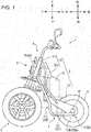
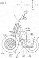
- the vehicle 1 is a vehicle that comprises a leanable body frame and two front wheels that are arranged side by side in a left-right direction of the body frame.
- the vehicle 1 comprises a vehicle main body 2, two front wheels 3, a rear wheel 4, a link mechanism 5 and a steering mechanism 6.
- the vehicle main body 2 comprises a body frame 21, a power unit 22, and a rear arm 23.
- the body frame 21 is in an upright state.
- the following description to be made with reference to Fig. 1 is based on the premise that the body frame 21 is in the upright state.
- Fig. 1 is a left side view resulting when the whole of the vehicle 1 is viewed from the left in the left-right direction of the body frame 21.
- the body frame 21 comprises a head pipe 211 and a main frame 212.
- the body frame 21 supports the power unit 22.
- the head pipe 211 is disposed at a front portion of the vehicle 1.
- an upper portion of the head pipe 211 is disposed behind a lower portion of the head pipe 211 in the front-rear direction of the body frame 21.
- the main frame 212 is connected to the head pipe 211.
- the main frame 212 is disposed behind the head pipe 211 in the front-rear direction of the body frame 21.
- the main frame 212 supports the power unit 22 and the rear arm 23.
- the rear arm 23 is disposed behind the main frame 212 in the front-rear direction of the body frame 21.
- the rear arm 23 extends in the front-rear direction of the body frame 21.
- a front end portion of the rear arm 23 is supported on the main frame 212 and is allowed to turn about an axis that extends in the left-right direction of the body frame 21.
- a rear end portion of the rear arm 23 supports the rear wheel 4.
- the two front wheels 3 are disposed below the head pipe 211 in an up-down direction of the body frame 21.
- the rear wheel 4 is disposed behind the two front wheels 3 in the front-rear direction of the body frame 21.
- the power unit 22 (an example of a driving power source) generates power which drives the vehicle 1.
- the power unit 22 When viewing the vehicle 1 in the left-right direction of the body frame 21, the power unit 22 is disposed ahead of an axle shaft 41 of the rear wheel 4 in the front-rear direction of the body frame 21.
- the power unit 22 is disposed so as not to be displaced relative to the body frame 21.
- the power unit 22 is disposed so as not to be displaced relative to the main frame 212.
- the power unit 22 includes an engine. Driving power generated by the engine is transmitted to the rear wheel 4 through a transmission mechanism.
- Fig. 2 is a front view of the front portion of the vehicle 1 as viewed from the front in the front-rear direction of the body frame 21.
- the body frame 21 is in the upright state.
- the following description to be made with reference to Fig. 2 is based on the premise that the body frame 21 is in the upright state.
- part of the vehicle main body portion 2 and the rear wheel 4 are omitted from illustration.
- the two front wheels 3 include a left front wheel 31 and a right front wheel 32.
- the left front wheel 31 is disposed on the left of the head pipe 211 which is a part of the body frame 21 in the left-right direction of the body frame 21.
- the right front wheel 32 is disposed on the right of the head pipe 211 in the left-right direction of the body frame 21.
- the left front wheel 31 and the right front wheel 32 are arranged side by side in the left-right direction of the body frame 21.
- the steering mechanism 6 includes a left shock absorbing mechanism 61, a right shock absorbing mechanism 62, a left bracket 63 and a right bracket 64.
- the left shock absorbing mechanism 61 includes a left lower portion 61 a.
- the left lower portion 61a supports the left front wheel 31.
- the left lower portion 61a extends in the up-down direction of the body frame 21.
- the left lower portion 61a comprises a left supporting portion 61b at a lower end portion thereof.
- the left front wheel 31 is supported on the left supporting portion 61b.
- the left shock absorbing mechanism 61 includes a left upper portion 61c.
- the left upper portion 61 c extends in the up-down direction of the body frame 21.
- the left upper portion 61c is disposed directly above the left lower portion 61a in the up-down direction of the body frame 21 while being partially inserted in the left lower portion 61 a.
- An upper portion of the left upper portion 61c is fixed to the left bracket 63.
- the left shock absorbing mechanism 61 and the left bracket 63 make up a left front wheel supporting portion.
- the left shock absorbing mechanism 61 is a so-called telescopic shock absorbing mechanism.
- the left upper portion 61c moves relative to the left lower portion 61a in a direction in which the left lower portion 61a extends, whereby the left shock absorbing mechanism 61 is allowed to extend and contract in the extending direction of the left lower portion 61 a.
- the right shock absorbing mechanism 62 includes a right lower portion 62a.
- the right lower portion 62a supports the right front wheel 32.
- the right lower portion 62a extends in the up-down direction of the body frame 21.
- the right lower portion 62a comprises a right supporting portion 62b at a lower end portion thereof.
- the right front wheel 32 is supported on the right supporting portion 62b.
- the right shock absorbing mechanism 62 includes a right upper portion 62c.
- the right upper portion 62c extends in the up-down direction of the body frame 21.
- the right upper portion 62c is disposed directly above the right lower portion 62a in the up-down direction of the body frame 21 while being partially inserted in the right lower portion 62a.
- An upper portion of the right upper portion 62c is fixed to the right bracket 64.
- the right shock absorbing mechanism 62 and the right bracket 64 make up a right front wheel supporting portion.
- the right shock absorbing mechanism 62 is a so-called telescopic shock absorbing mechanism.
- the right upper portion 62c moves relative to the right lower portion 62a in a direction in which the right lower portion 62a extends, whereby the right shock absorbing mechanism 62 is allowed to extend and contract in the extending direction of the right lower portion 62a. This enables the right shock absorbing mechanism 62 absorbs a displacement of the right front wheels 32 relative to the right upper portion 62c in the up-down direction of the body frame 21.
- the steering mechanism 6 includes a steering member 65.
- the steering member 65 includes a handlebar 651 and a steering shaft 652.
- the handlebar 651 is attached to an upper portion of the steering shaft 652.
- a portion of a steering shaft 652 is turnably supported on the head pipe 211.
- An intermediate steering axis Z of the steering shaft 652 extends in the up-down direction of the body frame 21.
- the upper portion of the steering shaft 652 is disposed behind a lower portion thereof in the front-rear direction of the body frame 21. Consequently, the intermediate steering axis Z of the steering shaft 652 is inclined in the front-rear direction of the body frame 21.
- the steering shaft 652 turns about the intermediate steering axis Z as a rider operates the handlebar 651.
- the link mechanism 5 adopts a four parallel joint link system (also referred to as a parallelogram link).
- the link mechanism 5 is disposed below the handlebar 651 in the up-down direction of the body frame 21.
- the link mechanism 5 is disposed above the left front wheel 31 and the right front wheel 32 in the up-down direction of the body frame 21.
- the link mechanism 5 includes an upper cross member 51, a lower cross member 52, a left side member 53 and a right side member 54.
- the link mechanism 5 is not interlocked with the turning of the steering shaft 652 about the intermediate steering axis Z associated with the operation of the handlebar 651. Namely, the link mechanism 5 does not turn about the intermediate steering axis Z relative to the body frame 21.
- the head pipe 211 has an upper intermediate connecting portion 211a.
- An intermediate portion of the upper cross member 51 is connected to the head pipe 211 by way of the upper intermediate connecting portion 211a.
- the upper cross member 51 is able to turn relative to the head pipe 211 about an upper intermediate connecting axis which passes the upper intermediate connecting portion 211a to extend in the front-rear direction of the body frame 21.
- the left side member 53 has an upper left connecting portion 53a.
- a left end portion of the upper cross member 51 is connected to the left side member 53 by way of the upper left connecting portion 53a.
- the upper cross member 51 is able to turn relative to the left side member 53 about an upper left connecting axis which passes the upper left connecting portion 53a to extend in the front-rear direction of the body frame 21.
- the right side member 54 has an upper right connecting portion 54a.
- a right end portion of the upper cross member 51 is connected to the right side member 54 by way of the upper right connecting portion 54a.
- the upper cross member 51 is able to turn relative to the right side member 54 about an upper right connecting axis which passes the upper right connecting portion 54a to extend in the front-rear direction of the body frame 21.
- the head pipe 211 has a lower intermediate connecting portion 211b.
- An intermediate portion of the lower cross member 52 is connected to the head pipe 211 by way of the lower intermediate connecting portion 211b.
- the lower cross member 52 is able to turn relative to the head pipe 211 about a lower intermediate connecting axis which passes the lower intermediate connecting portion 211 b to extend in the front-rear direction of the body frame 21.
- the left side member 53 has a lower left connecting portion 53b.
- a left end portion of the lower cross member 52 is connected to the left side member 53 by way of the lower left connecting portion 53b.
- the lower cross member 52 is able to turn relative to the left side member 53 about a lower left connecting axis which passes the lower left connecting portion 53b to extend in the front-rear direction of the body frame 21.
- the right side member 54 has a lower right connecting portion 54b.
- a right end portion of the lower cross member 52 is connected to the right side member 54 by way of the lower right connecting portion 54b.
- the lower cross member 52 is able to turn relative to the right side member 54 about a lower right connecting axis which passes the lower right connecting portion 54b to extend in the front-rear direction of the body frame 21.
- the upper intermediate connecting axis, the upper right connecting axis, the upper left connecting axis, the lower intermediate connecting axis, the lower right connecting axis and the lower left connecting axis extend parallel to one another.
- the upper intermediate connecting axis, the upper right connecting axis, the upper left connecting axis, the lower intermediate connecting axis, the lower right connecting axis and the lower left connecting axis are disposed above the left front wheel 31 and the right front wheel 32 in the up-down direction of the body frame 21.
- Fig. 3 is a plan view of the front portion of the vehicle 1 as viewed from the thereabove in the up-down direction of the body frame 21.
- the body frame 21 is in the upright state.
- the following description to be made with reference to Fig. 3 will be based on the premise that the body frame 21 is in the upright state.
- the upper cross member 51 is disposed ahead of the head pipe 211 in the front-rear direction of the body frame 21.
- the upper cross member 51 extends in the left-right direction of the body frame 21.
- the lower cross member 52 includes a front element 521 and a rear element 522.
- the front element 521 is disposed ahead of the head pipe 211 in the front-rear direction of the body frame 21.
- the rear element 522 is disposed behind the head pipe 211 in the front-rear direction of the body frame 21.
- the front element 521 and the rear element 522 extend in the left-right direction of the body frame 21.
- the lower cross member 52 is disposed below the upper cross member 51 in the up-down direction of the body frame 21.
- the left side member 53 is disposed directly on the left of the head pipe 211 in the left-right direction of the body frame 21.
- the left side member 53 is disposed above the left front wheel 31 in the up-down direction of the body frame 21.
- the left side member 53 extends in a direction in which the head pipe 211 extends.
- the left side member 53 extends in a direction in which the intermediate steering axis Z of the steering shaft 652 extends.
- An upper portion of the left side member 53 is disposed behind a lower portion thereof in the front-rear direction of the body frame 21.
- the left bracket 63 comprises a left turning member, not shown, at an upper portion thereof.
- the left turning member is disposed in an interior of the left side member 53 and extends in the same orientation as the direction in which the left side member 53 extends.
- the left turning member can turn about a left steering axis X relative to the left side member 53.
- the left bracket 63 can turn about the left steering axis X relative to the left side member 53.
- the left steering axis X extends in the direction in which the left side member 53 extends.
- the left steering axis X extends parallel to the intermediate steering axis Z of the steering shaft 652 in the up-down direction of the body frame 21.
- the left steering axis X extends parallel to the intermediate steering axis Z of the steering shaft 652 in the front-rear direction of the body frame 21.
- the right side member 54 is disposed directly on the right of the head pipe 211 in the left-right direction of the body frame 21.
- the right side member 54 is disposed above the right front wheel 32 in the up-down direction of the body frame 21.
- the right side member 54 extends in the direction in which the head pipe 211 extends.
- the right side member 54 extends in the direction in which the intermediate steering axis Z of the steering shaft 652 extends.
- An upper portion of the right side member 54 is disposed behind a lower portion thereof in the front-rear direction of the body frame 21.
- the right bracket 64 comprises a right turning member, not shown, at an upper portion thereof.
- the right turning member is disposed in an interior of the right side member 54 and extends in the same orientation as the direction in which the right side member 54 extends.
- the right turning member can turn about a right steering axis Y relative to the right side member 54.
- the right bracket 64 can turn about the right steering axis Y relative to the right side member 54.
- the right steering axis Y extends in the direction in which the right side member 54 extends.
- the right steering axis Y extends parallel to the intermediate steering axis Z of the steering shaft 652 in the up-down direction of the body frame 21.
- the right steering axis Y extends parallel to the intermediate steering axis Z of the steering shaft 652 in the front-rear direction of the body frame 21.
- the upper cross member 51, the lower cross member 52, the left side member 53 and the right side member 54 are supported on the body frame 21 so that the upper cross member 51 and the lower cross member 52 are held in postures which are parallel to each other while the left side member 53 and the right side member 54 are held in postures which are parallel to each other.
- the steering mechanism 6 includes a steering force transmission mechanism 66.
- the steering force transmission mechanism 66 transmits steering force with which the rider operates the handlebar 651 to the left bracket 63 and the right bracket 64.
- the steering force transmission mechanism 66 includes an intermediate transmission plate 663, a left transmission plate 664, a right transmission plate 665, an intermediate joint 666, a left joint 667, a right joint 668, and a tie rod 669.
- the intermediate transmission plate 663 is connected to a lower portion of the steering shaft 652.
- the intermediate transmission plate 663 cannot turn relative to the steering shaft 652.
- the intermediate transmission plate 663 can turn about the intermediate steering axis Z of the steering shaft 652 relative to the head pipe 211.
- the left transmission plate 664 is disposed directly on the left of the intermediate transmission plate 663.
- the left transmission plate 664 is connected to a lower portion of the left bracket 63.
- the left transmission plate 664 cannot turn relative to the left bracket 63.
- the left transmission plate 664 can turn about the left steering axis X relative to the left side member 53.
- the right transmission plate 665 is disposed directly on the right of the intermediate transmission plate 663 in the left-right direction of the body frame 21.
- the right transmission plate 665 is connected to a lower portion of the right bracket 64.
- the right transmission plate 665 is cannot turn relative to the right bracket 64.
- the right transmission plate 665 can turn about the right steering axis Y relative to the right side member 54.
- the intermediate joint 666 is connected to a front portion of the intermediate transmission plate 663 by way of a shaft portion which extends in the up-down direction of the body frame 21.
- the intermediate transmission plate 663 and the intermediate joint 666 are allowed to turn relative to each other about this shaft portion.
- the left joint 667 is disposed on the left of the intermediate joint 666 in the left-right direction of the body frame 21.
- the left joint 667 is connected to a front portion of the left transmission plate 664 by way of a shaft portion which extends in the up-down direction of the body frame 21.
- the left transmission plate 664 and the left joint 667 are allowed to turn relative to each other about this shaft portion.
- the right joint 668 is disposed on the right of the intermediate joint 666 in the left-right direction of the body frame 21.
- the right joint 668 is connected to a front portion of the right transmission plate 665 by way of a shaft portion which extends in the up-down direction of the body frame.
- the right transmission plate 665 and the right joint 668 are allowed to turn relative to each other about this shaft portion.
- a shaft portion which extends in the front-rear direction of the body frame 21 is provided at a front portion of the intermediate joint 666.
- a shaft portion which extends in the front-rear direction of the body frame 21 is provided at a front portion of the left joint 667.
- a shaft portion which extends in the front-rear direction of the body frame 21 is provided at a front portion of the right joint 668.
- the tie rod 669 extends in the left-right direction of the body frame 21.
- the tie rod 669 is connected to the intermediate joint 666, the left joint 667 and the right joint 668 by way of those shaft portions.
- the tie rod 669 and the intermediate joint 666 can turn relative to each other about the shaft portion which is provided at the front portion of the intermediate joint 666.
- the tie rod 669 and the left joint 667 can turn relative to each other about the shaft portion which is provided at the front portion of the left joint 667.
- the tie rod 669 and the right joint 668 can turn relative to each other about the shaft portion which is provided at the front portion of the right joint 668.
- the left transmission plate 664 is connected to the intermediate transmission plate 663 by way of the left joint 667, the tie rod 669, and the intermediate joint 666.
- the right transmission plate 665 is connected to the intermediate transmission plate 663 by way of the right joint 668, the tie rod 669 and the intermediate joint 666.
- the left transmission plate 664 and the right transmission plate 665 are connected to each other by way of the left joint 667, the tie rod 669 and the right joint 668.
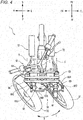
- Fig. 4 is a plan view of the front part of the vehicle 1 viewed from above in the up-down direction of the body frame 21 under a condition that the left front wheel 31 and the right front wheel 32 are steered to the left.
- the steering shaft 652 When the handlebar 651 is operated by the rider, the steering shaft 652 is turned about the intermediate steering axis Z relative to the head pipe 211. In the case shown in Fig. 4 where the front wheels are turned to the left, the steering shaft 652 turns in a direction indicated by an arrow T. In association with the turn of the steering shaft 652, the intermediate transmission plate 663 turns in the direction indicated by the arrow T about the intermediate steering axis Z relative to the head pipe 211.
- the intermediate joint 666 of the tie rod 669 turns relative to the intermediate transmission plate 663 in a direction indicated by an arrow S. This causes the tie rod 669 to move to the left in the left-right direction of the body frame 21 and to the rear in the front-rear direction of the body frame 21 while maintaining its posture.
- the left joint 667 and the right joint 668 of the tie rod 669 turn in the direction indicated by the arrow S relative to the left transmission plate 664 and the right transmission plate 665, respectively.
- This turns the left transmission plate 664 and the right transmission plate 665 in the direction indicated by the arrow T while allowing the tie rod 669 to maintain its posture.
- the left bracket 63 which is not able to turn relative to the left transmission plate 664, turns in the direction indicated by the arrow T about the left steering axis X relative to the left side member 53.
- the right bracket 64 which is not able to turn relative to the right transmission plate 665, turns in the direction indicated by the arrow T about the right steering axis Y relative to the right side member 54.
- the left shock absorbing mechanism 61 When the left bracket 63 is turned in the direction of the arrow T, the left shock absorbing mechanism 61, which is supported by the left bracket 63, turns in the direction of the arrow T about the left steering axis X relative to the left side member 53.
- the left shock absorbing mechanism 61 turns in the direction of the arrow T
- the left front wheel 31, which is supported on the left shock absorbing mechanism 61 by way of the left supporting portion 61b turns in the direction of the arrow T about the left steering axis X relative to the left side member 53.
- the right shock absorbing mechanism 62 When the right bracket 64 is turned in the direction of the arrow T, the right shock absorbing mechanism 62, which is supported by the right bracket 64, turns in the direction of the arrow T about the right steering axis Y relative to the right side member 54.
- the right shock absorbing mechanism 62 When the right shock absorbing mechanism 62 is turned in the direction of the arrow T, the right front wheel 32, which is supported on the right shock absorbing mechanism 62 by way of the right supporting portion 62b, turns in the direction of the arrow T about the right steering axis Y relative to the right side member 54.
- the steering force transmission mechanism 66 is configured so as to connect the left front wheel supporting portion and the right front wheel supporting portion together so that when the steering member 65 is operated to turn in the direction of the arrow T or S, the left front wheel 31 and the right front wheel 32 are turned in the direction concerned as the steering member 65 so turns.
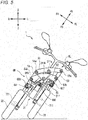
- FIG. 5 is a front view of the front portion of the vehicle 1 as viewed from the front in the front-rear direction of the body frame 21 under the condition that the body frame 21 leans to the left of the vehicle 1.
- part of the vehicle main body portion 2 and the rear wheel 4 are omitted from illustration.
- the link mechanism 5 when the vehicle 1 is viewed from the front of the body frame 21 under the condition that the body frame 21 is in an upright state, the link mechanism 5 has a rectangular shape. As shown in Fig. 5 , when the vehicle 1 is viewed from the front of the body frame 21 under the condition that the body frame 21 leans, the link mechanism 5 has a parallelogram shape. The operation of the link mechanism 5 is interlocked with the leaning of the body frame 21 in the left-right direction.
- the operation of the link mechanism 5 means that the upper cross member 51, the lower cross member 52, the left side member 53 and the right side member 54 which make up the link mechanism 5 turn relative to one another about the turning axes which pass the upper intermediate connecting portion 211 a, the upper left connecting portion 53a, the upper right connecting portion 54a, the lower intermediate connecting portion 211 b, the lower left connecting portion 53b and the lower right connecting portion 54b, respectively, whereby the shape of the link mechanism 5 changes.
- the head pipe 211 leans to the left from the vertical direction.
- the upper cross member 51 is turned counterclockwise about the upper intermediate connecting axis which passes the upper intermediate connecting portion 211 a relative to the head pipe 211 when viewed from the front of the vehicle 1.
- the lower cross member 52 is turned counterclockwise about the lower intermediate connecting axis which passes the lower intermediate connecting portion 211b relative to the head pipe 211 when viewed from the front of the vehicle 1. This causes the upper cross member 51 to move to the left in the left-right direction of the body frame 21 relative to the lower cross member 52.
- the upper cross member 51 is turned counterclockwise about the upper left connecting axis which passes the upper left connecting portion 53a and the upper right connecting axis which passes the upper right connecting portion 54a relative to the left side member 53 and the right side member 54, respectively, when viewed from the front of the vehicle 1.
- the lower cross member 52 is turned counterclockwise about the lower left connecting axis which passes the lower left connecting portion 53b and the lower right connecting axis which passes the lower right connecting portion 54b relative to the left side member 53 and the right side member 54, respectively, when viewed from the front of the vehicle 1.
- the lower cross member 52 moves to the left in the left-right direction of the body frame 21 relative to the tie rod 669.
- the shaft portions that are provided at the respective front portions of the intermediate joint 666, the left joint 667 and the right joint 668 turn relative to the tie rod 669. This allows the tie rod 669 to hold a posture that is parallel to the upper cross member 51 and the lower cross member 52.
- the left bracket 63 which is supported on the left side member 53 by way of the left turning member leans to the left of the vehicle 1.
- the left shock absorbing mechanism 61 which is supported by the left bracket 63 also leans to the left of the vehicle 1.
- the left shock absorbing mechanism 61 so leans, the left front wheel 31 which is supported on the left shock absorbing mechanism 61 leans to the left of the vehicle 1 while maintaining its posture which is parallel to the head pipe 211.
- the right bracket 64 which is supported on the right side member 54 by way of the right turning member leans to the left of the vehicle 1.
- the right shock absorbing mechanism 62 which is supported by the right bracket 64 also leans to the left of the vehicle 1.
- the right shock absorbing mechanism 64 so leans, the right front wheel 32 which is supported on the right shock absorbing mechanism 62 leans to the left of the vehicle 1 while maintaining its posture which is parallel to the head pipe 211.
- the description of the leaning operations of the left front wheel 31 and the right front wheel 32 is made relative to the vertical direction as a reference.
- the up-down direction of the body frame 21 does not coincide with the vertical direction.
- the link mechanism 5 when the link mechanism 5 is actuated to operate, the left front wheel 31 and the right front wheel 32 change their relative position in the up-down direction of the body frame 21.
- the link mechanism 5 changes the relative position of the left front wheel 31 and the right front wheel 32 in the up-down direction of the body frame 21 to thereby cause the body frame 21 to lean to the left or right of the vehicle 1 from the vertical direction.
- the vehicle 1 comprises a load transmission mechanism 7.
- the load transmission mechanism 7 includes a left foot rest portion 71 and a right foot rest portion 72.
- the left foot rest portion 71 includes a left foot placement face 711 and a left connecting member 712.
- the right foot rest portion 72 includes a right foot placement face 721 and a right connecting member 722.
- the configuration of the right foot rest portion 72 is symmetrical with the configuration of the left foot rest portion 71 when the vehicle 1 is viewed from the left in the left-right direction of the body frame 21.
- the illustration of the right foot rest portion 72 is omitted, and only reference numerals related thereto will be shown in Fig. 1 .
- the left foot placement face 711 is a portion where the left foot of the rider who rides on the vehicle 1 is placed.
- the left connecting member 712 connects the left foot placement face 711 and the left side member 53 of the link mechanism 5 together.
- the left connecting member 712 includes a left front portion 712a which extends in the up-down direction of the body frame 21 and a left rear portion 712b which extends in the front-rear direction of the body frame.
- the left front portion 712a is joined to the left side member 53.
- the left rear portion 712b is joined to the left foot placement face 711.
- the left foot rest portion 71 is configured to transmit a load inputted thereinto through the left foot placement face 711 to a left portion 5L of the link mechanism 5.
- the left portion 5L of the link mechanism 5 is a portion of the link mechanism 5 which is situated on the left of the upper intermediate connecting axis and the lower intermediate connecting axis in the left-right direction of the body frame 21.
- the right foot placement face 721 is a portion where the right foot of the rider who rides on the vehicle 1 is placed.
- the right connecting member 722 connects the right foot placement face 721 and the right side member 54 of the link mechanism 5 together.
- the right connecting member 722 includes a right front portion 722a which extends in the up-down direction of the body frame 21 and a right rear portion 722b which extends in the front-rear direction of the body frame.
- the right front portion 722a is joined to the right side member 54.
- the right rear portion 722b is joined to the right foot placement face 721.
- the right foot rest portion 72 is configured to transmit a load inputted thereinto through the right foot placement face 721 to a right portion 5R of the link mechanism 5.
- the right portion 5R of the link mechanism 5 means a portion of the link mechanism 5 which is situated on the right of the upper intermediate connecting axis and the lower intermediate connecting axis in the left-right direction of the body frame 21.
- the leaning of the body frame 21 can be controlled by individually controlling the load applied to the left foot placement face 711 through the left foot of the rider and the load applied to the right foot placement face 721 through the right foot of the rider.
- the left portion 5L of the link mechanism 5 including a left portion of the upper cross member 51, a left portion of the lower cross member 52 and the left side member 53 is displaced to a position above the right portion 5R of the link mechanism 5 including a right portion of the upper cross member 51, a right portion of the lower cross member 52 and the right side member 54 in the up-down direction of the body frame 21.
- the leaning of the vehicle 1 can be controlled without the necessity of providing a complicated mechanism such as an anti-rolling device described in Patent Literature 1.
- the leaning of the body frame 21 of the vehicle 1 equipped with the leanable body frame 21 and the two front wheels 3 can be controlled with the simpler configuration.
- the left foot rest portion 71 is provided on the left side member 53.
- the left side member 53 is a portion of the left portion 5L of the link mechanism 5 which can be displaced relative to the body frame 21 as the body frame 21 leans while being left unable to be displaced relative to the body frame 21 as the steering force transmission mechanism 66 is displaced.
- the right foot rest portion 72 is provided on the right side member 54.
- the right side member 54 is a portion of the right portion 5R of the link mechanism 5 which can be displaced relative to the body frame 21 as the body frame 21 leans while being left unable to be displaced relative to the body frame 21 as the steering force transmission mechanism 66 is displaced.
- the left foot placement face 711 and the right foot placement face 721 are not displaced in the direction in which the steering member 65 turns when the vehicle 1 is operated to be steered.
- the left foot placement face 711 and the right foot placement face 721 are allowed to move only in the up-down direction of the body frame 21 and in the directions in which the body frame 21 is caused to lean. Consequently, in providing the mechanism which controls the leaning of the body frame 21, the enlargement in size of the vehicle 1 can be suppressed.
- a moving range of each of the left side member 53 and the right side member 54 in the left-right direction of the body frame 21 when the vehicle 1 is caused to lean is less than a moving range in the up-down direction of the body frame 21 thereof. Consequently, the enlargement of the moving range of each of the left foot placement face 711 and the right foot placement face 721 when the vehicle 1 is caused to lean can be suppressed particularly in the left-right direction of the body frame 21. This advantageous effect becomes remarkable particularly in a case where the left foot placement face 711 and the right foot placement face 721 are situated farther away from the turning center of the lower cross member 52.
- a distance L1 between the lower intermediate connecting axis and a lower end 711D of the left foot placement face 711 is longer than a distance L2 between the lower intermediate connecting axis and the lower left intermediate connecting axis which passes the lower left connecting portion 53b.
- a distance L3 between the lower intermediate connecting axis and a lower end 721 D of the right foot placement face 721 is longer than a distance L4 between the lower intermediate connecting axis and the lower right intermediate connecting axis which passes the lower right connecting portion 54b.
- the left front portion 712a of the left connecting member 712 of the left foot rest portion 71 is joined integrally to the left side member 53. Namely, in the connecting portion, the left side member 53 and the left front portion 712a are not displaced relative to each other.
- the right front portion 722a of the right connecting member 722 of the right foot rest portion 72 is joined integrally to the right side member 54. Namely, in the connecting portion, the right side member 54 and the right front portion 722a are not displaced relative to each other.
- the configuration which can control the leaning of the body frame 21 of the vehicle 1 equipped with the leanable body frame 21 and the two front wheels 3 can be made simpler.
- the left foot placement face 711 is disposed below the left side member 53 in the up-down direction of the body frame 21.
- the right foot placement face 721 is disposed below the right side member 54 in the up-down direction of the body frame 21.
- the rider easily places his or her left foot and right foot on the left foot placement face 711 and the right foot placement face 721, respectively.
- the rider can mount and dismount from the vehicle 1 easily as well as the rider can obtain a good operation feeling.
- the left foot placement face 711 is disposed behind a rear end 31 B of the left front wheel 31 in the front-rear direction of the body frame 21.
- the right foot placement face 721 is disposed behind a rear end 32B of the right front wheel 32 in the front-rear direction of the body frame 21.
- the interference of the left foot placement face 711 with the left front wheel 31 may be easily avoided, as well as the interference of the right foot placement face 721 with the right front wheel 32 may be also avoided easily.
- a front end 711F of the left foot placement face 711 is disposed in a left rear section LBS when the vehicle 1 in which the body frame 21 is standing upright is viewed from the left in the left-right direction of the body frame 21.
- the left rear section LBS is defined by: a left central line LCL which extends in the up-down direction of the body frame 21 in such a way as to contain a left central point which is situated at a center between an axle shaft 311 of the left front wheel 31 and an axle shaft 41 of the rear wheel 4 in the front-rear direction of the body frame 21; and a left rear central line LBCL which extends in the up-down direction of the body frame 21 in such a way as to pass a left rear central point which is situated at a center between the left central point and the axle shaft 41 of the rear wheel 4 in the front-rear direction of the body frame 21.
- the front end 711 F of the left foot placement face 711 can be disposed in a left front section LFS when the vehicle 1 in which the body frame 21 is standing upright is viewed from the left in the left-right direction of the body frame 21.
- the left front section LFS is defined by the left central line LCL and a left front central line LFCL which extends in the up-down direction of the body frame 21 in such a way as to pass a left front central point which is situated at a center between the left central point and the axle shaft 311 of the left front wheel 31 in the front-rear direction of the body frame 21.
- a front end 721 F of the right foot placement face 721 is disposed in a right rear section RBS when the vehicle 1 in which the body frame 21 is standing upright is viewed from the right in the left-right direction of the body frame 21.
- the right rear section RBS is defined by: a right central line RCL which extends in the up-down direction of the body frame 21 in such a way as to contain a right central point which is situated at a center between an axle shaft 321 of the right front wheel 32 and the axle shaft 41 of the rear wheel 4 in the front-rear direction of the body frame 21; and a right rear central line RBCL which extends in the up-down direction of the body frame 21 in such a way as to pass a right rear central point which is situated at a center between the right central point and the axle shaft 41 of the rear wheel 4 in the front-rear direction of the body frame 21.
- the front end 721 F of the right foot placement face 721 can be disposed in a right front section RFS when the vehicle 1 in which the body frame 21 is standing upright is viewed from the right in the left-right direction of the body frame 21.
- the right front section RFS is defined by the right central line RCL and a right front central line RFCL which extends in the up-down direction of the body frame 21 in such a way as to pass a right front central point which is situated at a center between the right central point and the axle shaft 321 of the right front wheel 32 in the front-rear direction of the body frame 21.
- the center of gravity of the body is situated relatively forwards.
- the center of gravity of the body is located further forwards.
- the left foot placement face 711 and the right foot placement face 721 are respectively disposed behind the left rear section LBS and the right rear section RBS, loads applied through the left foot and the right foot of the rider are difficult to be transmitted to the link mechanism 5.
- the power unit 22 is disposed behind the link mechanism 5 in the front-rear direction of the body frame 21.
- the left foot placement face 711 is disposed on the left of a left end 22L of the power unit 22 in the left-right direction of the body frame 21.
- the right foot placement face 721 is disposed on the right of a right end 22R of the power unit 22 in the left-right direction of the body frame 21.
- the left foot placement face 711 and the right foot placement face 721 should be disposed so as to be spaced away from each other in the left-right direction of the body frame 21.
- the left shock absorbing mechanism 61 is connected to the left portion 5L of the link mechanism 5.
- the left shock absorbing mechanism 61 supports the left front wheel 31 and can change the length thereof in the up-down direction of the body frame 21.
- the right shock absorbing mechanism 62 is connected to the right portion 5R of the link mechanism 5.
- the right shock absorbing mechanism 62 supports the right front wheel 32 and can change the length thereof in the up-down direction of the body frame 21.
- the left shock absorbing mechanism 61 is interposed between the left portion 5L of the link mechanism 5 where the left foot rest portion 71 is provided and the left front wheel 31, it is possible to reduce the transmission of vibration from the left front wheel 31 to the left foot placement face 711.
- the right shock absorbing mechanism 62 is interposed between the right portion 5R of the link mechanism 5 where the right foot placement face 721 is provided and the right front wheel 32, it is possible to reduce the transmission of vibration from the right front wheel 32 to the right foot placement face 721. Consequently, the comfort in riding the vehicle 1 is enhanced.
- the left foot rest portion 71 of the load transmission mechanism 7 is joined integrally to the left side member 53 of the left portion 5L of the link mechanism 5.
- the right foot rest portion 72 of the load transmission mechanism 7 is joined integrally to the right side member 54 of the right portion 5R of the link mechanism 5.
- the left foot rest portion 71 and the right foot rest portion 72 may be provided at other portions of the link mechanism 5.
- Figs. 8 and 9 show a vehicle 1A according to such a modified example.
- Figs. 8 and 9 correspond to Figs. 2 and 5 , respectively.
- Like reference numerals are given to like constituent elements to those of the vehicle 1 according to the embodiment described above.
- a left foot rest portion 71 A comprises an upper left connecting member 713 and a lower left connecting member 714.
- the upper left connecting member 713 is connected to a left portion 51L of an upper cross member 51 in a left portion 5L of a link mechanism 5.
- the lower left connecting member 714 is connected to a left portion 52L of a lower cross member 52 in the left portion 5L of a link mechanism 5.
- the upper left connecting member 713 is allowed to turn about a left turning axis which extends parallel to an upper intermediate connecting axis which passes an upper intermediate connecting portion 211a.
- the lower left connecting member 714 is allowed to turn about a left turning axis which extends parallel to a lower intermediate connecting axis which passes a lower intermediate connecting portion 211 b.
- a right foot rest portion 72A comprises an upper right connecting member 723 and a lower right connecting member 724.
- the upper right connecting member 723 is connected to a right portion 51 R of the upper cross member 51 in a right portion 5R of the link mechanism 5.
- the lower right connecting member 724 is connected to a right portion 52R of the lower cross member 52 in the right portion 5R of the link mechanism 5.
- the upper right connecting member 723 is allowed to turn about a right turning axis which extends parallel to the upper intermediate connecting axis which passes the upper intermediate connecting portion 211a.
- the lower right connecting member 724 is allowed to turn about a right turning axis which extends parallel to the lower intermediate connecting axis which passes the lower intermediate connecting portion 211b.
- the left foot rest portion 71A turns relative to the upper cross member 51 and the lower cross member 52 while maintaining its posture which is substantially parallel to a left side member 53.
- the members are necessary which realize the turning operations, by disposing the upper left connecting member 713 and the lower left connecting member 714 nearer to a head pipe 211 than the left side member 53, the enlargement of the moving range of the left foot placement face 711 A when the vehicle 1A is caused to lean can be further suppressed.
- the right foot rest portion 72A turns relative to the upper cross member 51 and the lower cross member 52 while maintaining its posture which is substantially parallel to a right side member 54.
- the members are necessary which realize the turning operations, by disposing the upper right connecting member 723 and the lower right connecting member 724 nearer to the head pipe 211 than the right side member 54, the enlargement of the moving range of the right foot placement face 721 A when the vehicle 1A is caused to lean can be further suppressed.
- the left foot rest portion 71A including the upper left connecting member 713 and the lower left connecting member 714 which can move in the ways described above may be provided on the left side member 53 of the link mechanism 5.
- the right foot rest portion 72A including the upper right connecting member 723 and the lower right connecting member 724 which can move in the ways described above may be provided on the right side member 54 of the link mechanism 5.
- a configuration may be adopted in which the left foot rest portion 71 according to the embodiment is connected integrally to the left portion 51 L of the upper cross member 51 and the left portion 52L of the lower cross member 52.
- a configuration may be adopted in which the right foot rest portion 72 according to the embodiment is connected integrally to the right portion 51R of the upper cross member 51 and the right portion 52R of the lower cross member 52.
- the load transmission mechanism 7 is configured so that the load inputted into the left foot placement face 711 through the left foot of the rider is transmitted to the left portion 5L of the link mechanism 5 and that the load inputted into the right foot placement face 721 through the right foot of the rider is inputted into the right portion 5R of the link mechanism 5.
- the load transmission mechanism 7 including an appropriate link mechanism a configuration may be adopted in which the load inputted into the left foot placement face 711 through the left foot of the rider is transmitted to the right portion 5R of the link mechanism 5 and the load inputted into the right foot placement face 721 through the right foot of the rider is inputted into the left portion 5L of the link mechanism 5.
- the link mechanism 5 comprises the upper cross member 51 and the lower cross member 52.
- the link mechanism 5 comprises a cross member other than the upper cross member 51 and the lower cross member 52.
- the "upper cross member” and the “lower cross member” are merely so called based on their relative positional relationship in the up-down direction.
- the upper cross member does not mean an uppermost cross member in the link mechanism 5.
- the upper cross member means a cross member which lies above another cross member which lies therebelow.
- the lower cross member does not mean a lowermost cross member in the link mechanism 5.
- the lower cross member means a cross member which lies below another cross member which lies thereabove.
- the upper cross member 51 is the single plate-shaped member, while the lower cross member 52 comprises the front element 521 and the rear element 522.
- a configuration may be adopted in which the upper cross member 51 comprises a front element and a rear element.
- a configuration may be adopted in which the lower cross member 52 is made up of a single plate-shaped member.
- a configuration may be adopted in which at least one of the upper cross member 51 and the lower cross member 52 comprises: a left plate-shaped member which is supported on the head pipe 211 and the left side member 53; and a right plate-shaped member which is supported on the head pipe 211 and the right side member 54.
- the handlebar 651 is made up of the single member which extends in the left-right direction of the body frame.
- the handlebar 651 is made up of a left handlebar portion configured to be operated by the left hand of the rider and a right handlebar portion configured to be operated by the right hand of the rider which are provided as individual separate members, as long as steering force to turn the left front wheel 31 and the right front wheel 32 can be inputted through the handlebar 651.
- the link mechanism 5 is supported on the head pipe 211 which is an example of a link supporting portion.
- the link mechanism 5 is supported on part of the body frame 21 other than the head pipe 211 which supports the steering shaft 652.
- the steering force transmission mechanism 66 includes the intermediate transmission plate 663, the left transmission plate 664, the right transmission plate 665, the intermediate joint 666, the left joint 667, the right joint 668, and the tie rod 669.
- the intermediate transmission plate 663, the left transmission plate 664, the right transmission plate 665, the intermediate joint 666, the left joint 667 and the right joint 668 may be replaced by appropriate mechanisms such as universal joints.
- the word “parallel” means that two straight lines which do not intersect each other as members while they are inclined at an angle falling within the range of ⁇ 40 degrees are comprised therein.
- the expression reading "along a certain direction” means that a case where something inclines at an angle falling within the range of ⁇ 40 degrees relative to the certain direction is comprised therein.
- the expression reading "something extends in a certain direction” means that a case where something extends while being inclined at an angle falling within the range of ⁇ 40 degrees relative to the certain direction is comprised therein.
- the expression “displace along” means displacement in a direction coincident with or parallel to a reference direction.
- the expression “displace along” is used in this description in connection with the direction of an arc motion, it means displacement along any arc that is concentric with a center of curvature of a reference arc.
- the expression “so as not to be movable relative to the body frame 21” means that a certain part or member is caused to lean in the left-right direction of the vehicle 1 together with the body frame 21 when the body frame 21 is caused to lean in the left-right direction of the vehicle 1.
- the expression “so as not to be movable relative to the body frame 21” may comprehend not only a case where a certain part or member is directly fixed to the body frame but also a case where the certain part of member is fixed to a vehicle component (a fuel tank, a bracket, the power unit 22, etc.) which is fixed on the body frame 21.
- the term “fixed” may comprehend a case that a certain part or member is fixed by way of a damping member or the like.
Landscapes
- Engineering & Computer Science (AREA)
- Mechanical Engineering (AREA)
- Automatic Cycles, And Cycles In General (AREA)
- Passenger Equipment (AREA)
- Vehicle Step Arrangements And Article Storage (AREA)
Abstract
Description
- The present disclosure relates to a vehicle equipped with a leanable body frame and two front wheels.
- A vehicle described in, for example, Patent Literature 1 comprises a body frame and two front wheels that are arranged side by side in a left-right direction of the body frame.
- The vehicle comprises a link mechanism. The link mechanism is disposed above the two front wheels. The link mechanism is configured so as to change positions of the two front wheels relative to the body frame to thereby cause the body frame to lean to the left or right of the vehicle. In addition, the vehicle described above comprises an anti-roll device in order to restrict the leaning of the body frame.
[Patent Literature 1] Japanese Patent Publication No.2005-313876 A - For a vehicle equipped with a leanable body frame and two front wheels, there is a need to restrict the leaning of the body frame with a simpler configuration.
- According to the present invention said object is solved by a vehicle having the features of independent claim 1. A vehicle according to a preferred embodiment includes
a body frame;
a left front wheel and a right front wheel that are arranged side by side in a left-right direction of the body frame;
a link mechanism disposed above the left front wheel and the right front wheel in an up-down direction of the body frame, and comprising an upper cross member, a lower cross member, a left side member and a right side member that are connected with each other such that the upper cross member and the lower cross member are configured to maintain their postures parallel to each other while the left side member and the right side member are configured to maintain their postures parallel to each other, thereby being configured to change positions of the left front wheel and the right front wheel relative to the body frame to cause the body frame to lean to left or right of the vehicle;
a left front wheel supporting portion connected to the link mechanism and supporting the left front wheel;
a right front wheel supporting portion connected to the link mechanism and supporting the right front wheel; and
a load transmission mechanism comprising a left foot placement face on which a left foot of a driver riding the vehicle is to be placed and a right foot placement face on which a right foot of the driver is to be placed, configured to transmit a load to a left portion of the link mechanism by way of one of the left foot placement face and the right foot placement face, and configured to transmit a load to a right portion of the link mechanism by way of the other one of the left foot placement face and the right foot placement face. - It should be noted that the "left portion" of a member represents a portion that is situated on the left of a center of that member in the left-right direction of the body frame. Similarly, the "right portion" of a member represents a portion that is situated on the left of a center of that member in the left-right direction of the body frame.
- According to the configuration described above, the leaning of the body frame can be controlled by individually controlling the load applied to the left foot placement face through the left foot of the rider and the load applied to the right foot placement face through the right foot of the rider.
- For example, when the body frame leans to the left of the vehicle, the left portion of the link mechanism including the left portion of the upper cross member, the left portion of the lower cross member and the left side member is displaced to a position above the right portion of the link mechanism including the right portion of the upper cross member, the right portion of the lower cross member and the right side member in the up-down direction of the body frame. As this occurs, when a load is applied to the left portion of the link mechanism through the left foot placement face by the left foot of the rider, a force acts to displace the left portion of the link mechanism downwards, whereby the leaning of the body frame to the left of the vehicle can be suppressed. On the contrary, when the body frame leans to the right of the vehicle, the right portion of the link mechanism is displaced to a position above the left portion of the link mechanism in the up-down direction of the body frame. As this occurs, when a load is applied to the right portion of the link mechanism through the right foot placement face by the right foot of the rider, a force acts to displace the right portion of the link mechanism downwards in the up-down direction of the body frame, whereby the leaning of the body frame to the right of the vehicle can be suppressed.
- Since the load is applied directly to the link mechanism through the foot of the rider, the leaning of the vehicle can be controlled without the necessity of providing a complicated mechanism such as an anti-rolling device described in Patent Literature 1. As a result, the leaning of the body frame of the vehicle equipped with the leanable body frame and the two front wheels can be controlled with the simpler configuration.
- The above vehicle may be configured so as to further comprise:
- a steering member provided so as to be turnable about a turning axis relative to the body frame; and
- a steering force transmission mechanism is configured to interconnect the left front wheel supporting portion and the right front wheel supporting portion, and configured to cause the left front wheel and the right front wheel to turn in a direction that the steering member is turned, wherein:
- a left foot placement portion including the left foot placement face and provided in such a portion of the left portion of the link mechanism that is able to displace relative to the body frame in accordance with leaning of the body frame but is not able to displace relative to the body frame in accordance with motion of the steering force transmission mechanism; and
- a right foot placement portion including the right foot placement face and provided in such a portion of the right portion of the link mechanism that is able to displace relative to the body frame in accordance with leaning of the body frame but is not able to displace relative to the body frame in accordance with motion of the steering force transmission mechanism.
- According to the configuration as described above, since the left foot placement face and the right foot placement face are provided in such portions that are not able to displace relative to the body frame in accordance with the motion of the steering force transmission mechanism, they are not displaced in the direction in which the steering member turns when the vehicle is operated to be steered. In other words, the left foot placement face and the right foot placement face are allowed to move only in the up-down direction of the body frame and in the directions in which the body frame is caused to lean. Consequently, in providing the mechanism which controls the leaning of the body frame, the enlargement in size of the vehicle can be suppressed.
- In this case, the above vehicle may be configured such that:
- the upper cross member is connected to the body frame so as to be turnable about an upper intermediate connecting axis;
- the lower cross member is connected to the body frame so as to be turnable about a lower intermediate connecting axis;
- a left portion of the upper cross member is connected to an upper portion of the left side member so as to be turnable about an upper left connecting axis;
- a right portion of the upper cross member is connected to an upper portion of the right side member so as to be turnable about an upper right connecting axis;
- a left portion of the lower cross member is connected to a lower portion of the left side member so as to be turnable about a lower left connecting axis;
- a right portion of the lower cross member is connected to a lower portion of the right side member so as to be turnable about a lower right connecting axis;
- a portion of the lower cross member that is positioned directly above the lower intermediate connecting axis is configured to overlap the upper cross member, as viewed from the front in the direction following the lower intermediate connecting axis;
- the left front wheel supporting portion is connected to the left side member so as to be turnable in accordance with motion of the steering force transmission mechanism;
- the right front wheel supporting portion is connected to the right side member so as to be turnable in accordance with motion of the steering force transmission mechanism;
- the left foot placement portion is provided on the left side member; and
- the right foot placement portion is provided on the right side member.
- A moving range of each of the left side member and the right side member in the left-right direction of the body frame when the vehicle is caused to lean is less than a moving range in the up-down direction of the body frame thereof. Consequently, the enlargement of the moving range of each of the left foot placement face and the right foot placement face when the vehicle is caused to lean can be suppressed particularly in the left-right direction of the body frame. This advantageous effect becomes remarkable particularly in a case where the left foot placement face and the right foot placement face are situated farther away from the turning center of the lower cross member.
- As an example of such a case, the above vehicle may be configured such that:
- a distance between the lower intermediate connecting axis and a lower end of the left foot placement face is longer than a distance between the lower intermediate connecting axis and the lower left connecting axis, when the vehicle in which the body frame is in an upright state is viewed from front in a direction along the lower intermediate connecting axis; and
- a distance between the lower intermediate connecting axis and a lower end of the right foot placement face is longer than a distance between the lower intermediate connecting axis and the lower right connecting axis, when the vehicle in which the body frame is in an upright state is viewed from front in the direction along the lower intermediate connecting axis.
- In addition, the vehicle may be configured such that:
- the left foot placement portion is joined integrally to the left side member; and
- the right foot placement portion is joined integrally to the right side member.
- It should be noted that the expression "joined integrally to" means that two members are not displaced relative to each other at a joined portion by welding, fastening, or the like.
- According to the configuration described above, the configuration which can control the leaning of the body frame of the vehicle equipped with the leanable body frame and the two front wheels can be made simpler.
- Alternatively, the above vehicle may be configured such that:
- the upper cross member is connected to the body frame so as to be turnable about the upper intermediate connecting axis;
- the lower cross member is connected to the body frame so as to be turnable about the lower intermediate connecting axis;
- the left foot placement portion comprises:
- an upper left connecting member connected to the left portion of the upper cross member so as to be turnable about an upper left turning axis extending in a direction parallel to the upper intermediate connecting axis; and
- a lower left connecting member connected to the left portion of the lower cross member so as to be turnable about a lower left turning axis extending in a direction parallel to the lower intermediate connecting axis; and
- the right foot placement portion comprises:
- an upper right connecting member connected to the right portion of the upper cross member so as to be turnable about an upper right turning axis extending in the direction parallel to the upper intermediate connecting axis; and
- a lower right connecting member connected to the right portion of the lower cross member so as to be turnable about a lower right turning axis extending in the direction parallel to the lower intermediate connecting axis.
- According to the configuration described above, when the vehicle is caused to lean, the left foot rest portion turns relative to the upper cross member and the lower cross member while maintaining its posture which is substantially parallel to the left side member. Although the members are necessary which realize the turning operations, by disposing the upper left connecting member and the lower left connecting member on the right of the left side member in the left-right direction of the body frame, the enlargement of the moving range of the left foot placement face when the vehicle is caused to lean can be further suppressed.
- On the other hand, the right foot rest portion turns relative to the upper cross member and the lower cross member while maintaining its posture which is substantially parallel to a right side member. Although the members are necessary which realize the turning operations, by disposing the upper right connecting member and the lower right connecting member on the left of the right side member in the left-right direction of the body frame, the enlargement of the moving range of the right foot placement face when the vehicle is caused to lean can be further suppressed.
- The above vehicle may be configured such that:
- the left foot placement face is disposed below the left side member in an up-down direction of the body frame; and
- the right foot placement face is disposed below the right side member in the up-down direction of the body frame.
- According to the configuration described above, the rider easily places his or her left foot and right foot on the left foot placement face and the right foot placement face, respectively. Thus, the rider can mount and dismount from the vehicle easily as well as the rider can obtain a good operation feeling.
- The above vehicle may be configured such that:
- the left foot placement face is disposed behind a rear end of the left front wheel in a front-rear direction of the body frame; and
- the right foot placement face is disposed behind a rear end of the right front wheel in the front-rear direction of the body frame.
- According to the configuration described above, when the vehicle is steered or is caused to lean, the interference of the left foot placement face with the left front wheel may be easily avoided, as well as the interference of the right foot placement face with the right front wheel may be also avoided easily.
- In this case, the vehicle may be configured so as to further comprise a rear wheel, wherein:
- a front end of the left foot placement face is situated in either one of a left front section and a left rear section, when the vehicle in which the body frame is in an upright state is viewed from left in a left-right direction of the body frame;
- the left front section is defined by:
- a left central line extending in an up-down direction of the body frame so as to include a left central point situated at a center between an axle of the left front wheel and the rear wheel in the front-rear direction of the body frame; and
- a left front central line extending in the up-down direction of the body frame so as to include a left front central point situated at a center between the left central point and the axle of the left front wheel in the front-rear direction of the body frame;
- the left rear section is defined by the left central line and a left rear central line extending in the up-down direction of the body frame so as to include a left rear central point situated at a center between the left central point and the axle of the rear wheel in the front-rear direction of the body frame;
- a front end of the right foot placement face is situated in either one of a right front section and a right rear section, when the vehicle in which the body frame is in the upright state is viewed from right in the left-right direction of the body frame;
- the right front section is defined by:
- a right central line extending in the up-down direction of the body frame so as to include a right central point situated at a center between an axle of the right front wheel and the rear wheel in the front-rear direction of the body frame; and
- a right front central line extending in the up-down direction of the body frame so as to include a right front central point situated at a center between the right central point and the axle of the right front wheel in the front-rear direction of the body frame; and
- the right rear section is defined by the right central line and a right rear central line extending in the up-down direction of the body frame so as to include a right rear central point situated at a center between the right central point and the axle of the rear wheel in the front-rear direction of the body frame.
- Since the vehicle is configured to comprise the two front wheels and the link mechanism, the center of gravity of the body is situated relatively forwards. In the event that the left foot placement face and the right foot placement face are respectively disposed ahead of the left front section and the right front section, the center of gravity of the body is located further forwards. On the other hand, in the event that the left foot placement face and the right foot placement face are respectively disposed behind the left rear section and the right rear section, loads applied through the left foot and the right foot of the rider are difficult to be transmitted to the link mechanism. According to the configuration described above, not only the center of gravity of the vehicle in operation is allowed to be situated in a proper position but also the loads are allowed to be applied easily.
- In addition, the above vehicle may be configured so as to further comprise a driving power source disposed behind the link mechanism in the front-rear direction of the body frame, and configured to supply driving power of the vehicle, wherein:
- the left foot placement face is disposed on the left of a left end of the driving power source in the left-right direction of the body frame; and
- the right foot placement face is disposed on the right of a right end of the driving power source in the left-right direction of the body frame.
- In order to transmit the loads applied through the left foot and the right foot of the rider to the link mechanism in an effective fashion, the left foot placement face and the right foot placement face should be disposed so as to be spaced away from each other in the left-right direction of the body frame. By disposing the driving power source having a relatively large volume in the space defined in the way described above, it is possible to enhance the utilization efficiency of the space.
- The above vehicle may be configured such that:
- the left front wheel supporting portion comprises a left shock absorbing mechanism connected to the left portion of the link mechanism so as to be able to change a length thereof in an up-down direction of the body frame; and
- the right front wheel supporting portion comprises a right shock absorbing mechanism connected to the right portion of the link mechanism so as to be able to change a length thereof in the up-down direction of the body frame.
- According to the configuration described above, since the left shock absorbing mechanism is interposed between the left portion of the link mechanism where the left foot rest portion is provided and the left front wheel, it is possible to reduce the transmission of vibration from the left front wheel to the left foot placement face. Similarly, since the right shock absorbing mechanism is interposed between the right portion of the link mechanism where the right foot placement face is provided and the right front wheel, it is possible to reduce the transmission of vibration from the right front wheel to the right foot placement face. Consequently, the comfort in riding the vehicle is enhanced.
-
-
Fig. 1 is a left side view entirely showing a vehicle according to one embodiment. -
Fig. 2 is a front view showing a front portion of the vehicle ofFig. 1 . -
Fig. 3 is a plan view showing the front portion of the vehicle ofFig. 1 . -
Fig. 4 is a plan view showing the front portion of the vehicle ofFig. 1 when steering is performed. -
Fig. 5 is a front view showing the front portion of the vehicle ofFig. 1 when leaning is performed. -
Fig. 6 is a plan view showing the front portion of the vehicle ofFig. 1 . -
Fig. 7 is a left side view entirely showing the vehicle ofFig. 1 . -
Fig. 8 is a plan view showing a front portion of a vehicle according to a modified example. -
Fig. 9 is a front view showing the front portion of the vehicle ofFig. 8 when leaning is performed. - Referring to the accompanying drawings, an exemplary embodiment will be described in detail below.
- In the accompanying drawings, an arrow F denotes a front or forward direction of a vehicle. An arrow B denotes a back/rear or backward/rearward direction of the vehicle. An arrow U denotes an up or upward direction of the vehicle. An arrow D denotes a down or downward direction of the vehicle. An arrow R denotes a right or rightward direction of the vehicle. An arrow L denotes a left or leftward direction of the vehicle.
- A vehicle turns with a body frame being caused to lean to the left or right of the vehicle from a vertical direction. Then, in addition to the directions based on the vehicle, directions based on the body frame will be defined. In the accompanying drawings, an arrow FF denotes a front or forward direction of the body frame. An arrow FB denotes a back/rear or backward/rearward of the body frame. An arrow FU denotes an up or upward direction of the body frame. An arrow FD denotes a down or downward direction of the body frame. An arrow FR denotes a right or rightward direction of the body frame. An arrow FL denotes a left or leftward direction of the body frame.
- In this description, a "front-rear direction of the body frame," a "left-right direction of the body frame" and an "up-down direction of the body frame" mean a front-rear direction, a left-right direction and an up-down direction based on the body frame when viewed from a rider who rides the vehicle. "A side of or sideways of the body frame" means directly on the right or left in the left-right direction of the body frame.
- In this description, an expression "extending in the front-rear direction of the vehicle body frame" includes a fact that it extends while being inclined in relation to the front-rear direction of the vehicle body frame and means that it extends in a direction closer to the front-rear direction of the vehicle body frame than the left-right direction and up-down direction of the vehicle body frame.
- In this description, an expression "extending in the left-right direction of the vehicle body frame" includes a fact that it extends while being inclined in relation to the left-right direction of the vehicle body frame and means that it extends in a direction closer to the left-right direction of the vehicle body frame than the front-rear direction and up-down direction of the vehicle body frame.
- In this description, an expression "extending in the up-down direction of the vehicle body frame" includes a fact that it extends while being inclined in relation to the up-down direction of the vehicle body frame and means that it extends in a direction closer to the up-down direction of the vehicle body frame than the left-right direction and front-rear direction of the vehicle body frame.
- In this description, an expression reading the "vehicle is standing upright or in an upright state" or the "body frame is standing upright or in the upright state" means a state in which the vehicle is not steered at all and the up-down direction of the body frame coincides with the vertical direction. In this state, the directions based on the vehicle coincide with the directions based on the body frame. When the vehicle is turning with the body frame caused to lean to the left or right from the vertical direction, the left-right direction of the vehicle does not coincide with the left-right direction of the body frame. Similarly, the up-down direction of the vehicle does not coincide with the up-down direction of the body frame. However, the front-rear direction of the vehicle coincides with the front-rear direction of the body frame.
- In this description, an expression reading "directly on the left of a member A in the left-right direction of the body frame" denotes a space through which the member A passes when the member A is translated to the left in the left-right direction of the body frame. An expression reading "directly on the right of the member A" is also defined in the same way.
- In this description, an expression reading "on the left of the member A in the left-right direction of the body frame" includes not only the space through which the member A passes when the member A is translated to the left in the left-right direction of the body frame but also a space which expands from the space in directions which are at right angles to the left-right direction of the body frame. An expression reading "on the right of the member A" is also defined in the same way.
- In this description, an expression reading "directly above the member A in the up-down direction of the body frame" denotes a space through which the member A passes when the member A is translated upwards in the up-down direction of the body frame. An expression reading "directly below the member A" is also defined in the same way.
- In this description, an expression reading "above the member A in the up-down direction of the body frame" includes not only the space through which the member A passes when the member A is translated upwards in the up-down direction of the body frame but also a space which expands from the space in directions which are at right angles to the up-down direction of the body frame. An expression reading "below the member A" is also defined in the same way.
- In this description, an expression reading "directly ahead of the member A in the front-rear direction of the body frame" denotes a space through which the member A passes when the member A is translated to the front in the front-rear direction of the body frame. An expression reading "directly behind the member A" is also defined in the same way.
- In this description, an expression reading "ahead of the member A in the front-rear direction of the body frame" includes not only the space through which the member A passes when the member A is translated to the front in the front-rear direction of the body frame but also a space which expands from the space in directions which are at right angles to the front-rear direction of the body frame. An expression reading "behind the member A" is also defined in the same way.
- In this description, "rotation, rotating or rotated" means that a member is displaced at an angle of 360 degrees or more about an axis thereof. In this description, "turn, turning or turned" means that a member is displaced at an angle less than 360 degrees about an axis thereof.
- Referring to
Figs. 1 to 7 , a vehicle 1 according to an embodiment of the invention will be described. The vehicle 1 is a vehicle that comprises a leanable body frame and two front wheels that are arranged side by side in a left-right direction of the body frame. - As shown in
Fig. 1 , the vehicle 1 comprises a vehiclemain body 2, twofront wheels 3, arear wheel 4, a link mechanism 5 and asteering mechanism 6. - The vehicle
main body 2 comprises abody frame 21, apower unit 22, and arear arm 23. InFig. 1 , thebody frame 21 is in an upright state. The following description to be made with reference toFig. 1 is based on the premise that thebody frame 21 is in the upright state.Fig. 1 is a left side view resulting when the whole of the vehicle 1 is viewed from the left in the left-right direction of thebody frame 21. - The
body frame 21 comprises ahead pipe 211 and amain frame 212. Thebody frame 21 supports thepower unit 22. - The
head pipe 211 is disposed at a front portion of the vehicle 1. When viewing the vehicle 1 from the left in the left-right direction of thebody frame 21, an upper portion of thehead pipe 211 is disposed behind a lower portion of thehead pipe 211 in the front-rear direction of thebody frame 21. - The
main frame 212 is connected to thehead pipe 211. Themain frame 212 is disposed behind thehead pipe 211 in the front-rear direction of thebody frame 21. Themain frame 212 supports thepower unit 22 and therear arm 23. - The
rear arm 23 is disposed behind themain frame 212 in the front-rear direction of thebody frame 21. Therear arm 23 extends in the front-rear direction of thebody frame 21. A front end portion of therear arm 23 is supported on themain frame 212 and is allowed to turn about an axis that extends in the left-right direction of thebody frame 21. A rear end portion of therear arm 23 supports therear wheel 4. - The two
front wheels 3 are disposed below thehead pipe 211 in an up-down direction of thebody frame 21. Therear wheel 4 is disposed behind the twofront wheels 3 in the front-rear direction of thebody frame 21. - The power unit 22 (an example of a driving power source) generates power which drives the vehicle 1. When viewing the vehicle 1 in the left-right direction of the
body frame 21, thepower unit 22 is disposed ahead of anaxle shaft 41 of therear wheel 4 in the front-rear direction of thebody frame 21. Thepower unit 22 is disposed so as not to be displaced relative to thebody frame 21. Thepower unit 22 is disposed so as not to be displaced relative to themain frame 212. Thepower unit 22 includes an engine. Driving power generated by the engine is transmitted to therear wheel 4 through a transmission mechanism. -
Fig. 2 is a front view of the front portion of the vehicle 1 as viewed from the front in the front-rear direction of thebody frame 21. InFig. 2 , thebody frame 21 is in the upright state. The following description to be made with reference toFig. 2 is based on the premise that thebody frame 21 is in the upright state. InFig. 2 , part of the vehiclemain body portion 2 and therear wheel 4 are omitted from illustration. - The two
front wheels 3 include aleft front wheel 31 and a rightfront wheel 32. Theleft front wheel 31 is disposed on the left of thehead pipe 211 which is a part of thebody frame 21 in the left-right direction of thebody frame 21. Theright front wheel 32 is disposed on the right of thehead pipe 211 in the left-right direction of thebody frame 21. Theleft front wheel 31 and theright front wheel 32 are arranged side by side in the left-right direction of thebody frame 21. - The
steering mechanism 6 includes a leftshock absorbing mechanism 61, a rightshock absorbing mechanism 62, aleft bracket 63 and aright bracket 64. - The left
shock absorbing mechanism 61 includes a leftlower portion 61 a. The leftlower portion 61a supports theleft front wheel 31. The leftlower portion 61a extends in the up-down direction of thebody frame 21. The leftlower portion 61a comprises a left supportingportion 61b at a lower end portion thereof. Theleft front wheel 31 is supported on theleft supporting portion 61b. - The left
shock absorbing mechanism 61 includes a left upper portion 61c. The left upper portion 61 c extends in the up-down direction of thebody frame 21. The left upper portion 61c is disposed directly above the leftlower portion 61a in the up-down direction of thebody frame 21 while being partially inserted in the leftlower portion 61 a. An upper portion of the left upper portion 61c is fixed to theleft bracket 63. The leftshock absorbing mechanism 61 and theleft bracket 63 make up a left front wheel supporting portion. - The left
shock absorbing mechanism 61 is a so-called telescopic shock absorbing mechanism. The left upper portion 61c moves relative to the leftlower portion 61a in a direction in which the leftlower portion 61a extends, whereby the leftshock absorbing mechanism 61 is allowed to extend and contract in the extending direction of the leftlower portion 61 a. This enables the leftshock absorbing mechanism 61 absorbs a displacement of the leftfront wheels 31 relative to the left upper portion 61 c in the up-down direction of thebody frame 21 . - The right
shock absorbing mechanism 62 includes a rightlower portion 62a. The rightlower portion 62a supports theright front wheel 32. The rightlower portion 62a extends in the up-down direction of thebody frame 21. The rightlower portion 62a comprises aright supporting portion 62b at a lower end portion thereof. Theright front wheel 32 is supported on theright supporting portion 62b. - The right
shock absorbing mechanism 62 includes a rightupper portion 62c. The rightupper portion 62c extends in the up-down direction of thebody frame 21. The rightupper portion 62c is disposed directly above the rightlower portion 62a in the up-down direction of thebody frame 21 while being partially inserted in the rightlower portion 62a. An upper portion of the rightupper portion 62c is fixed to theright bracket 64. The rightshock absorbing mechanism 62 and theright bracket 64 make up a right front wheel supporting portion. - The right
shock absorbing mechanism 62 is a so-called telescopic shock absorbing mechanism. The rightupper portion 62c moves relative to the rightlower portion 62a in a direction in which the rightlower portion 62a extends, whereby the rightshock absorbing mechanism 62 is allowed to extend and contract in the extending direction of the rightlower portion 62a. This enables the rightshock absorbing mechanism 62 absorbs a displacement of the rightfront wheels 32 relative to the rightupper portion 62c in the up-down direction of thebody frame 21. - The
steering mechanism 6 includes a steeringmember 65. The steeringmember 65 includes ahandlebar 651 and asteering shaft 652. Thehandlebar 651 is attached to an upper portion of thesteering shaft 652. A portion of asteering shaft 652 is turnably supported on thehead pipe 211. An intermediate steering axis Z of thesteering shaft 652 extends in the up-down direction of thebody frame 21. As shown inFig. 1 , the upper portion of thesteering shaft 652 is disposed behind a lower portion thereof in the front-rear direction of thebody frame 21. Consequently, the intermediate steering axis Z of thesteering shaft 652 is inclined in the front-rear direction of thebody frame 21. The steeringshaft 652 turns about the intermediate steering axis Z as a rider operates thehandlebar 651. - In the vehicle 1 according to this embodiment, the link mechanism 5 adopts a four parallel joint link system (also referred to as a parallelogram link).
- As shown in
Fig. 2 , the link mechanism 5 is disposed below thehandlebar 651 in the up-down direction of thebody frame 21. The link mechanism 5 is disposed above theleft front wheel 31 and theright front wheel 32 in the up-down direction of thebody frame 21. The link mechanism 5 includes anupper cross member 51, alower cross member 52, aleft side member 53 and aright side member 54. The link mechanism 5 is not interlocked with the turning of thesteering shaft 652 about the intermediate steering axis Z associated with the operation of thehandlebar 651. Namely, the link mechanism 5 does not turn about the intermediate steering axis Z relative to thebody frame 21. - The
head pipe 211 has an upper intermediate connectingportion 211a. An intermediate portion of theupper cross member 51 is connected to thehead pipe 211 by way of the upper intermediate connectingportion 211a. Theupper cross member 51 is able to turn relative to thehead pipe 211 about an upper intermediate connecting axis which passes the upper intermediate connectingportion 211a to extend in the front-rear direction of thebody frame 21. - The
left side member 53 has an upperleft connecting portion 53a. A left end portion of theupper cross member 51 is connected to theleft side member 53 by way of the upperleft connecting portion 53a. Theupper cross member 51 is able to turn relative to theleft side member 53 about an upper left connecting axis which passes the upperleft connecting portion 53a to extend in the front-rear direction of thebody frame 21. - The
right side member 54 has an upperright connecting portion 54a. A right end portion of theupper cross member 51 is connected to theright side member 54 by way of the upperright connecting portion 54a. Theupper cross member 51 is able to turn relative to theright side member 54 about an upper right connecting axis which passes the upperright connecting portion 54a to extend in the front-rear direction of thebody frame 21. - The
head pipe 211 has a lower intermediate connectingportion 211b. An intermediate portion of thelower cross member 52 is connected to thehead pipe 211 by way of the lower intermediate connectingportion 211b. Thelower cross member 52 is able to turn relative to thehead pipe 211 about a lower intermediate connecting axis which passes the lower intermediate connectingportion 211 b to extend in the front-rear direction of thebody frame 21. - The
left side member 53 has a lowerleft connecting portion 53b. A left end portion of thelower cross member 52 is connected to theleft side member 53 by way of the lowerleft connecting portion 53b. Thelower cross member 52 is able to turn relative to theleft side member 53 about a lower left connecting axis which passes the lowerleft connecting portion 53b to extend in the front-rear direction of thebody frame 21. - The
right side member 54 has a lowerright connecting portion 54b. A right end portion of thelower cross member 52 is connected to theright side member 54 by way of the lowerright connecting portion 54b. Thelower cross member 52 is able to turn relative to theright side member 54 about a lower right connecting axis which passes the lowerright connecting portion 54b to extend in the front-rear direction of thebody frame 21. - The upper intermediate connecting axis, the upper right connecting axis, the upper left connecting axis, the lower intermediate connecting axis, the lower right connecting axis and the lower left connecting axis extend parallel to one another. The upper intermediate connecting axis, the upper right connecting axis, the upper left connecting axis, the lower intermediate connecting axis, the lower right connecting axis and the lower left connecting axis are disposed above the
left front wheel 31 and theright front wheel 32 in the up-down direction of thebody frame 21. -
Fig. 3 is a plan view of the front portion of the vehicle 1 as viewed from the thereabove in the up-down direction of thebody frame 21. InFig. 3 , thebody frame 21 is in the upright state. The following description to be made with reference toFig. 3 will be based on the premise that thebody frame 21 is in the upright state. - The
upper cross member 51 is disposed ahead of thehead pipe 211 in the front-rear direction of thebody frame 21. Theupper cross member 51 extends in the left-right direction of thebody frame 21. - The
lower cross member 52 includes afront element 521 and arear element 522. Thefront element 521 is disposed ahead of thehead pipe 211 in the front-rear direction of thebody frame 21. Therear element 522 is disposed behind thehead pipe 211 in the front-rear direction of thebody frame 21. Thefront element 521 and therear element 522 extend in the left-right direction of thebody frame 21. Thelower cross member 52 is disposed below theupper cross member 51 in the up-down direction of thebody frame 21. - As shown in
Figs. 2 and3 , theleft side member 53 is disposed directly on the left of thehead pipe 211 in the left-right direction of thebody frame 21. Theleft side member 53 is disposed above theleft front wheel 31 in the up-down direction of thebody frame 21. Theleft side member 53 extends in a direction in which thehead pipe 211 extends. Theleft side member 53 extends in a direction in which the intermediate steering axis Z of thesteering shaft 652 extends. An upper portion of theleft side member 53 is disposed behind a lower portion thereof in the front-rear direction of thebody frame 21. - The
left bracket 63 comprises a left turning member, not shown, at an upper portion thereof. The left turning member is disposed in an interior of theleft side member 53 and extends in the same orientation as the direction in which theleft side member 53 extends. The left turning member can turn about a left steering axis X relative to theleft side member 53. Namely, theleft bracket 63 can turn about the left steering axis X relative to theleft side member 53. The left steering axis X extends in the direction in which theleft side member 53 extends. As shown inFig. 2 , the left steering axis X extends parallel to the intermediate steering axis Z of thesteering shaft 652 in the up-down direction of thebody frame 21. As shown inFig. 3 , the left steering axis X extends parallel to the intermediate steering axis Z of thesteering shaft 652 in the front-rear direction of thebody frame 21. - As shown in
Figs. 2 and3 , theright side member 54 is disposed directly on the right of thehead pipe 211 in the left-right direction of thebody frame 21. Theright side member 54 is disposed above theright front wheel 32 in the up-down direction of thebody frame 21. Theright side member 54 extends in the direction in which thehead pipe 211 extends. Theright side member 54 extends in the direction in which the intermediate steering axis Z of thesteering shaft 652 extends. An upper portion of theright side member 54 is disposed behind a lower portion thereof in the front-rear direction of thebody frame 21. - The
right bracket 64 comprises a right turning member, not shown, at an upper portion thereof. The right turning member is disposed in an interior of theright side member 54 and extends in the same orientation as the direction in which theright side member 54 extends. The right turning member can turn about a right steering axis Y relative to theright side member 54. Namely, theright bracket 64 can turn about the right steering axis Y relative to theright side member 54. The right steering axis Y extends in the direction in which theright side member 54 extends. As shown inFig. 2 , the right steering axis Y extends parallel to the intermediate steering axis Z of thesteering shaft 652 in the up-down direction of thebody frame 21. As shown inFig. 3 , the right steering axis Y extends parallel to the intermediate steering axis Z of thesteering shaft 652 in the front-rear direction of thebody frame 21. - Thus, as has been described above, the
upper cross member 51, thelower cross member 52, theleft side member 53 and theright side member 54 are supported on thebody frame 21 so that theupper cross member 51 and thelower cross member 52 are held in postures which are parallel to each other while theleft side member 53 and theright side member 54 are held in postures which are parallel to each other. - The
steering mechanism 6 includes a steeringforce transmission mechanism 66. The steeringforce transmission mechanism 66 transmits steering force with which the rider operates thehandlebar 651 to theleft bracket 63 and theright bracket 64. As shown inFig. 3 , the steeringforce transmission mechanism 66 includes anintermediate transmission plate 663, aleft transmission plate 664, aright transmission plate 665, an intermediate joint 666, a left joint 667, a right joint 668, and atie rod 669. - The
intermediate transmission plate 663 is connected to a lower portion of thesteering shaft 652. Theintermediate transmission plate 663 cannot turn relative to thesteering shaft 652. Theintermediate transmission plate 663 can turn about the intermediate steering axis Z of thesteering shaft 652 relative to thehead pipe 211. - The
left transmission plate 664 is disposed directly on the left of theintermediate transmission plate 663. Theleft transmission plate 664 is connected to a lower portion of theleft bracket 63. Theleft transmission plate 664 cannot turn relative to theleft bracket 63. Theleft transmission plate 664 can turn about the left steering axis X relative to theleft side member 53. - The
right transmission plate 665 is disposed directly on the right of theintermediate transmission plate 663 in the left-right direction of thebody frame 21. Theright transmission plate 665 is connected to a lower portion of theright bracket 64. Theright transmission plate 665 is cannot turn relative to theright bracket 64. Theright transmission plate 665 can turn about the right steering axis Y relative to theright side member 54. - As shown in
Fig. 3 , the intermediate joint 666 is connected to a front portion of theintermediate transmission plate 663 by way of a shaft portion which extends in the up-down direction of thebody frame 21. Theintermediate transmission plate 663 and the intermediate joint 666 are allowed to turn relative to each other about this shaft portion. The left joint 667 is disposed on the left of the intermediate joint 666 in the left-right direction of thebody frame 21. The left joint 667 is connected to a front portion of theleft transmission plate 664 by way of a shaft portion which extends in the up-down direction of thebody frame 21. Theleft transmission plate 664 and the left joint 667 are allowed to turn relative to each other about this shaft portion. The right joint 668 is disposed on the right of the intermediate joint 666 in the left-right direction of thebody frame 21. The right joint 668 is connected to a front portion of theright transmission plate 665 by way of a shaft portion which extends in the up-down direction of the body frame. Theright transmission plate 665 and the right joint 668 are allowed to turn relative to each other about this shaft portion. - A shaft portion which extends in the front-rear direction of the
body frame 21 is provided at a front portion of theintermediate joint 666. A shaft portion which extends in the front-rear direction of thebody frame 21 is provided at a front portion of theleft joint 667. A shaft portion which extends in the front-rear direction of thebody frame 21 is provided at a front portion of the right joint 668. Thetie rod 669 extends in the left-right direction of thebody frame 21. Thetie rod 669 is connected to the intermediate joint 666, the left joint 667 and the right joint 668 by way of those shaft portions. Thetie rod 669 and the intermediate joint 666 can turn relative to each other about the shaft portion which is provided at the front portion of theintermediate joint 666. Thetie rod 669 and the left joint 667 can turn relative to each other about the shaft portion which is provided at the front portion of theleft joint 667. Thetie rod 669 and the right joint 668 can turn relative to each other about the shaft portion which is provided at the front portion of the right joint 668. - The
left transmission plate 664 is connected to theintermediate transmission plate 663 by way of the left joint 667, thetie rod 669, and theintermediate joint 666. Theright transmission plate 665 is connected to theintermediate transmission plate 663 by way of the right joint 668, thetie rod 669 and theintermediate joint 666. Theleft transmission plate 664 and theright transmission plate 665 are connected to each other by way of the left joint 667, thetie rod 669 and the right joint 668. - Next, referring to
Figs. 3 and4 , a steering operation of the vehicle 1 will be described.Fig. 4 is a plan view of the front part of the vehicle 1 viewed from above in the up-down direction of thebody frame 21 under a condition that theleft front wheel 31 and theright front wheel 32 are steered to the left. - When the
handlebar 651 is operated by the rider, the steeringshaft 652 is turned about the intermediate steering axis Z relative to thehead pipe 211. In the case shown inFig. 4 where the front wheels are turned to the left, the steeringshaft 652 turns in a direction indicated by an arrow T. In association with the turn of thesteering shaft 652, theintermediate transmission plate 663 turns in the direction indicated by the arrow T about the intermediate steering axis Z relative to thehead pipe 211. - In association with the turning of the
intermediate transmission plate 663 in the direction indicated by the arrow T, theintermediate joint 666 of thetie rod 669 turns relative to theintermediate transmission plate 663 in a direction indicated by an arrow S. This causes thetie rod 669 to move to the left in the left-right direction of thebody frame 21 and to the rear in the front-rear direction of thebody frame 21 while maintaining its posture. - In association with the movement of the
tie rod 669, the left joint 667 and theright joint 668 of thetie rod 669 turn in the direction indicated by the arrow S relative to theleft transmission plate 664 and theright transmission plate 665, respectively. This turns theleft transmission plate 664 and theright transmission plate 665 in the direction indicated by the arrow T while allowing thetie rod 669 to maintain its posture. - When the
left transmission plate 664 turns in the direction indicated by the arrow T, theleft bracket 63, which is not able to turn relative to theleft transmission plate 664, turns in the direction indicated by the arrow T about the left steering axis X relative to theleft side member 53. - When the
right transmission plate 665 is turned in the direction indicated by the arrow T, theright bracket 64, which is not able to turn relative to theright transmission plate 665, turns in the direction indicated by the arrow T about the right steering axis Y relative to theright side member 54. - When the
left bracket 63 is turned in the direction of the arrow T, the leftshock absorbing mechanism 61, which is supported by theleft bracket 63, turns in the direction of the arrow T about the left steering axis X relative to theleft side member 53. When the leftshock absorbing mechanism 61 turns in the direction of the arrow T, theleft front wheel 31, which is supported on the leftshock absorbing mechanism 61 by way of theleft supporting portion 61b, turns in the direction of the arrow T about the left steering axis X relative to theleft side member 53. - When the
right bracket 64 is turned in the direction of the arrow T, the rightshock absorbing mechanism 62, which is supported by theright bracket 64, turns in the direction of the arrow T about the right steering axis Y relative to theright side member 54. When the rightshock absorbing mechanism 62 is turned in the direction of the arrow T, theright front wheel 32, which is supported on the rightshock absorbing mechanism 62 by way of theright supporting portion 62b, turns in the direction of the arrow T about the right steering axis Y relative to theright side member 54. - When the rider operates the
handlebar 651 so as to steer to the right, the elements described above turn in opposite directions to the directions in which they turn when the vehicle turns to the left. Since the elements merely move the other way around in relation to the left-right direction, the detailed description thereof will be omitted here. - Namely, the steering
force transmission mechanism 66 is configured so as to connect the left front wheel supporting portion and the right front wheel supporting portion together so that when the steeringmember 65 is operated to turn in the direction of the arrow T or S, theleft front wheel 31 and theright front wheel 32 are turned in the direction concerned as the steeringmember 65 so turns. - Next, referring to
Figs. 2 and5 , a leaning operation of the vehicle 1 will be described.Fig. 5 is a front view of the front portion of the vehicle 1 as viewed from the front in the front-rear direction of thebody frame 21 under the condition that thebody frame 21 leans to the left of the vehicle 1. InFig. 5 , part of the vehiclemain body portion 2 and therear wheel 4 are omitted from illustration. - As shown in
Fig. 2 , when the vehicle 1 is viewed from the front of thebody frame 21 under the condition that thebody frame 21 is in an upright state, the link mechanism 5 has a rectangular shape. As shown inFig. 5 , when the vehicle 1 is viewed from the front of thebody frame 21 under the condition that thebody frame 21 leans, the link mechanism 5 has a parallelogram shape. The operation of the link mechanism 5 is interlocked with the leaning of thebody frame 21 in the left-right direction. The operation of the link mechanism 5 means that theupper cross member 51, thelower cross member 52, theleft side member 53 and theright side member 54 which make up the link mechanism 5 turn relative to one another about the turning axes which pass the upper intermediate connectingportion 211 a, the upperleft connecting portion 53a, the upperright connecting portion 54a, the lower intermediate connectingportion 211 b, the lowerleft connecting portion 53b and the lowerright connecting portion 54b, respectively, whereby the shape of the link mechanism 5 changes. - For example, as shown in
Fig. 5 , when the rider causes the vehicle 1 to lean to the left, thehead pipe 211 leans to the left from the vertical direction. When thehead pipe 211 is caused to lean, theupper cross member 51 is turned counterclockwise about the upper intermediate connecting axis which passes the upper intermediate connectingportion 211 a relative to thehead pipe 211 when viewed from the front of the vehicle 1. Similarly, thelower cross member 52 is turned counterclockwise about the lower intermediate connecting axis which passes the lower intermediate connectingportion 211b relative to thehead pipe 211 when viewed from the front of the vehicle 1. This causes theupper cross member 51 to move to the left in the left-right direction of thebody frame 21 relative to thelower cross member 52. - By moving in the way described above, the
upper cross member 51 is turned counterclockwise about the upper left connecting axis which passes the upperleft connecting portion 53a and the upper right connecting axis which passes the upperright connecting portion 54a relative to theleft side member 53 and theright side member 54, respectively, when viewed from the front of the vehicle 1. Similarly, thelower cross member 52 is turned counterclockwise about the lower left connecting axis which passes the lowerleft connecting portion 53b and the lower right connecting axis which passes the lowerright connecting portion 54b relative to theleft side member 53 and theright side member 54, respectively, when viewed from the front of the vehicle 1. This causes theleft side member 53 and theright side member 54 to lean to the left of the vehicle 1 from the vertical direction while holding their postures parallel to thehead pipe 211. - As this occurs, the
lower cross member 52 moves to the left in the left-right direction of thebody frame 21 relative to thetie rod 669. As a result of thelower cross member 52 moving in the way described above, the shaft portions that are provided at the respective front portions of the intermediate joint 666, the left joint 667 and the right joint 668 turn relative to thetie rod 669. This allows thetie rod 669 to hold a posture that is parallel to theupper cross member 51 and thelower cross member 52. - As the
left side member 53 leans to the left of the vehicle 1, theleft bracket 63 which is supported on theleft side member 53 by way of the left turning member leans to the left of the vehicle 1. As theleft bracket 63 so leans, the leftshock absorbing mechanism 61 which is supported by theleft bracket 63 also leans to the left of the vehicle 1. As the leftshock absorbing mechanism 61 so leans, theleft front wheel 31 which is supported on the leftshock absorbing mechanism 61 leans to the left of the vehicle 1 while maintaining its posture which is parallel to thehead pipe 211. - As the
right side member 54 leans to the left of the vehicle 1, theright bracket 64 which is supported on theright side member 54 by way of the right turning member leans to the left of the vehicle 1. As theright bracket 64 so leans, the rightshock absorbing mechanism 62 which is supported by theright bracket 64 also leans to the left of the vehicle 1. As the rightshock absorbing mechanism 64 so leans, theright front wheel 32 which is supported on the rightshock absorbing mechanism 62 leans to the left of the vehicle 1 while maintaining its posture which is parallel to thehead pipe 211. - The description of the leaning operations of the
left front wheel 31 and theright front wheel 32 is made relative to the vertical direction as a reference. However, while the leaning operation of the vehicle 1 (during the operation of the link mechanism 5), the up-down direction of thebody frame 21 does not coincide with the vertical direction. In a case where the up-down direction of thebody frame 21 is set as the reference, when the link mechanism 5 is actuated to operate, theleft front wheel 31 and theright front wheel 32 change their relative position in the up-down direction of thebody frame 21. In other words, the link mechanism 5 changes the relative position of theleft front wheel 31 and theright front wheel 32 in the up-down direction of thebody frame 21 to thereby cause thebody frame 21 to lean to the left or right of the vehicle 1 from the vertical direction. - When the rider causes the vehicle 1 to lean to the right, the elements lean to the right. Since the elements merely move the other way around in relation to the left-right direction, the detailed description thereof will be omitted here.
- As shown in
Figs. 1 and3 , the vehicle 1 comprises aload transmission mechanism 7. Theload transmission mechanism 7 includes a leftfoot rest portion 71 and a rightfoot rest portion 72. The leftfoot rest portion 71 includes a leftfoot placement face 711 and a left connectingmember 712. The rightfoot rest portion 72 includes a rightfoot placement face 721 and aright connecting member 722. The configuration of the rightfoot rest portion 72 is symmetrical with the configuration of the leftfoot rest portion 71 when the vehicle 1 is viewed from the left in the left-right direction of thebody frame 21. Thus, the illustration of the rightfoot rest portion 72 is omitted, and only reference numerals related thereto will be shown inFig. 1 . - The left
foot placement face 711 is a portion where the left foot of the rider who rides on the vehicle 1 is placed. Theleft connecting member 712 connects the leftfoot placement face 711 and theleft side member 53 of the link mechanism 5 together. As shown inFig. 1 , theleft connecting member 712 includes aleft front portion 712a which extends in the up-down direction of thebody frame 21 and a leftrear portion 712b which extends in the front-rear direction of the body frame. Theleft front portion 712a is joined to theleft side member 53. The leftrear portion 712b is joined to the leftfoot placement face 711. - The left
foot rest portion 71 is configured to transmit a load inputted thereinto through the leftfoot placement face 711 to aleft portion 5L of the link mechanism 5. As shown inFig. 3 , theleft portion 5L of the link mechanism 5 is a portion of the link mechanism 5 which is situated on the left of the upper intermediate connecting axis and the lower intermediate connecting axis in the left-right direction of thebody frame 21. - The right
foot placement face 721 is a portion where the right foot of the rider who rides on the vehicle 1 is placed. Theright connecting member 722 connects the rightfoot placement face 721 and theright side member 54 of the link mechanism 5 together. As shown inFig. 1 , theright connecting member 722 includes aright front portion 722a which extends in the up-down direction of thebody frame 21 and a rightrear portion 722b which extends in the front-rear direction of the body frame. Theright front portion 722a is joined to theright side member 54. The rightrear portion 722b is joined to the rightfoot placement face 721. - The right
foot rest portion 72 is configured to transmit a load inputted thereinto through the rightfoot placement face 721 to aright portion 5R of the link mechanism 5. As shown inFig. 3 , theright portion 5R of the link mechanism 5 means a portion of the link mechanism 5 which is situated on the right of the upper intermediate connecting axis and the lower intermediate connecting axis in the left-right direction of thebody frame 21. - According to the configuration described above, the leaning of the
body frame 21 can be controlled by individually controlling the load applied to the leftfoot placement face 711 through the left foot of the rider and the load applied to the rightfoot placement face 721 through the right foot of the rider. - For example, when the
body frame 21 leans to the left of the vehicle 1 as shown inFig. 5 , theleft portion 5L of the link mechanism 5 including a left portion of theupper cross member 51, a left portion of thelower cross member 52 and theleft side member 53 is displaced to a position above theright portion 5R of the link mechanism 5 including a right portion of theupper cross member 51, a right portion of thelower cross member 52 and theright side member 54 in the up-down direction of thebody frame 21. As this occurs, when a load is applied to theleft portion 5L of the link mechanism 5 through the leftfoot placement face 711 by the left foot of the rider, a force acts to displace theleft portion 5L of the link mechanism 5 downwards, whereby the leaning of thebody frame 21 to the left of the vehicle 1 can be suppressed. - On the contrary, when the body frame leans to the right of the vehicle 1, the
right portion 5R of the link mechanism 5 is displaced to a position above theleft portion 5L of the link mechanism 5 in the up-down direction of thebody frame 21. As this occurs, when a load is applied to theright portion 5R of the link mechanism 5 through the rightfoot placement face 721 by the right foot of the rider, a force acts to displace theright portion 5R of the link mechanism 5 downwards in the up-down direction of thebody frame 21, whereby the leaning of thebody frame 21 to the right of the vehicle 1 can be suppressed. - Since the load is applied directly to the link mechanism 5 through the foot of the rider, the leaning of the vehicle 1 can be controlled without the necessity of providing a complicated mechanism such as an anti-rolling device described in Patent Literature 1. As a result, the leaning of the
body frame 21 of the vehicle 1 equipped with theleanable body frame 21 and the twofront wheels 3 can be controlled with the simpler configuration. - In the above embodiment, the left
foot rest portion 71 is provided on theleft side member 53. Theleft side member 53 is a portion of theleft portion 5L of the link mechanism 5 which can be displaced relative to thebody frame 21 as thebody frame 21 leans while being left unable to be displaced relative to thebody frame 21 as the steeringforce transmission mechanism 66 is displaced. On the other hand, the rightfoot rest portion 72 is provided on theright side member 54. Theright side member 54 is a portion of theright portion 5R of the link mechanism 5 which can be displaced relative to thebody frame 21 as thebody frame 21 leans while being left unable to be displaced relative to thebody frame 21 as the steeringforce transmission mechanism 66 is displaced. - Namely, as is clear from
Figs. 3 and4 , the leftfoot placement face 711 and the rightfoot placement face 721 are not displaced in the direction in which the steeringmember 65 turns when the vehicle 1 is operated to be steered. In other words, as shown inFig. 5 , the leftfoot placement face 711 and the rightfoot placement face 721 are allowed to move only in the up-down direction of thebody frame 21 and in the directions in which thebody frame 21 is caused to lean. Consequently, in providing the mechanism which controls the leaning of thebody frame 21, the enlargement in size of the vehicle 1 can be suppressed. - Further, as is clear from
Fig. 5 , a moving range of each of theleft side member 53 and theright side member 54 in the left-right direction of thebody frame 21 when the vehicle 1 is caused to lean is less than a moving range in the up-down direction of thebody frame 21 thereof. Consequently, the enlargement of the moving range of each of the leftfoot placement face 711 and the rightfoot placement face 721 when the vehicle 1 is caused to lean can be suppressed particularly in the left-right direction of thebody frame 21. This advantageous effect becomes remarkable particularly in a case where the leftfoot placement face 711 and the rightfoot placement face 721 are situated farther away from the turning center of thelower cross member 52. - To describe this specifically, as shown in
Fig. 6 , when the vehicle 1 in which thebody frame 21 is standing upright is viewed from the front in the direction along the lower intermediate connecting axis which passes the lower intermediate connectingportion 211b, a distance L1 between the lower intermediate connecting axis and alower end 711D of the leftfoot placement face 711 is longer than a distance L2 between the lower intermediate connecting axis and the lower left intermediate connecting axis which passes the lowerleft connecting portion 53b. On the other hand, when the vehicle 1 in which thebody frame 21 is standing upright is viewed from the front in the direction along the lower intermediate connecting axis which passes the lower intermediate connectingportion 211b, a distance L3 between the lower intermediate connecting axis and alower end 721 D of the rightfoot placement face 721 is longer than a distance L4 between the lower intermediate connecting axis and the lower right intermediate connecting axis which passes the lowerright connecting portion 54b. - In this embodiment, the
left front portion 712a of theleft connecting member 712 of the leftfoot rest portion 71 is joined integrally to theleft side member 53. Namely, in the connecting portion, theleft side member 53 and theleft front portion 712a are not displaced relative to each other. On the other hand, theright front portion 722a of theright connecting member 722 of the rightfoot rest portion 72 is joined integrally to theright side member 54. Namely, in the connecting portion, theright side member 54 and theright front portion 722a are not displaced relative to each other. - According to the configuration described above, the configuration which can control the leaning of the
body frame 21 of the vehicle 1 equipped with theleanable body frame 21 and the twofront wheels 3 can be made simpler. - In this embodiment, as shown in
Figs. 5 and6 , the leftfoot placement face 711 is disposed below theleft side member 53 in the up-down direction of thebody frame 21. On the other hand, the rightfoot placement face 721 is disposed below theright side member 54 in the up-down direction of thebody frame 21. - According to the configuration described above, the rider easily places his or her left foot and right foot on the left
foot placement face 711 and the rightfoot placement face 721, respectively. Thus, the rider can mount and dismount from the vehicle 1 easily as well as the rider can obtain a good operation feeling. - As shown in
Fig. 3 , the leftfoot placement face 711 is disposed behind arear end 31 B of theleft front wheel 31 in the front-rear direction of thebody frame 21. On the other hand, the rightfoot placement face 721 is disposed behind arear end 32B of theright front wheel 32 in the front-rear direction of thebody frame 21. - According to the configuration described above, when the vehicle 1 is steered or is caused to lean, the interference of the left
foot placement face 711 with theleft front wheel 31 may be easily avoided, as well as the interference of the rightfoot placement face 721 with theright front wheel 32 may be also avoided easily. - In this embodiment, as shown in
Fig. 7 , afront end 711F of the leftfoot placement face 711 is disposed in a left rear section LBS when the vehicle 1 in which thebody frame 21 is standing upright is viewed from the left in the left-right direction of thebody frame 21. The left rear section LBS is defined by: a left central line LCL which extends in the up-down direction of thebody frame 21 in such a way as to contain a left central point which is situated at a center between anaxle shaft 311 of theleft front wheel 31 and anaxle shaft 41 of therear wheel 4 in the front-rear direction of thebody frame 21; and a left rear central line LBCL which extends in the up-down direction of thebody frame 21 in such a way as to pass a left rear central point which is situated at a center between the left central point and theaxle shaft 41 of therear wheel 4 in the front-rear direction of thebody frame 21. - The
front end 711 F of the leftfoot placement face 711 can be disposed in a left front section LFS when the vehicle 1 in which thebody frame 21 is standing upright is viewed from the left in the left-right direction of thebody frame 21. The left front section LFS is defined by the left central line LCL and a left front central line LFCL which extends in the up-down direction of thebody frame 21 in such a way as to pass a left front central point which is situated at a center between the left central point and theaxle shaft 311 of theleft front wheel 31 in the front-rear direction of thebody frame 21. - On the other hand, a
front end 721 F of the rightfoot placement face 721 is disposed in a right rear section RBS when the vehicle 1 in which thebody frame 21 is standing upright is viewed from the right in the left-right direction of thebody frame 21. The right rear section RBS is defined by: a right central line RCL which extends in the up-down direction of thebody frame 21 in such a way as to contain a right central point which is situated at a center between anaxle shaft 321 of theright front wheel 32 and theaxle shaft 41 of therear wheel 4 in the front-rear direction of thebody frame 21; and a right rear central line RBCL which extends in the up-down direction of thebody frame 21 in such a way as to pass a right rear central point which is situated at a center between the right central point and theaxle shaft 41 of therear wheel 4 in the front-rear direction of thebody frame 21. - The
front end 721 F of the rightfoot placement face 721 can be disposed in a right front section RFS when the vehicle 1 in which thebody frame 21 is standing upright is viewed from the right in the left-right direction of thebody frame 21. The right front section RFS is defined by the right central line RCL and a right front central line RFCL which extends in the up-down direction of thebody frame 21 in such a way as to pass a right front central point which is situated at a center between the right central point and theaxle shaft 321 of theright front wheel 32 in the front-rear direction of thebody frame 21. - Since the vehicle is configured to comprise the two
front wheels 3 and the link mechanism 5, the center of gravity of the body is situated relatively forwards. In the event that the leftfoot placement face 711 and the rightfoot placement face 721 are respectively disposed ahead of the left front section LFS and the right front section RFS, the center of gravity of the body is located further forwards. On the other hand, in the event that the leftfoot placement face 711 and the rightfoot placement face 721 are respectively disposed behind the left rear section LBS and the right rear section RBS, loads applied through the left foot and the right foot of the rider are difficult to be transmitted to the link mechanism 5. According to the configuration described above, not only the center of gravity of the vehicle in operation is allowed to be situated in a proper position but also the loads are allowed to be applied easily. - In this embodiment, as shown in
Fig. 3 , thepower unit 22 is disposed behind the link mechanism 5 in the front-rear direction of thebody frame 21. The leftfoot placement face 711 is disposed on the left of a left end 22L of thepower unit 22 in the left-right direction of thebody frame 21. The rightfoot placement face 721 is disposed on the right of aright end 22R of thepower unit 22 in the left-right direction of thebody frame 21. - In order to transmit the loads applied through the left foot and the right foot of the rider to the link mechanism 5 in an effective fashion, the left
foot placement face 711 and the rightfoot placement face 721 should be disposed so as to be spaced away from each other in the left-right direction of thebody frame 21. By disposing thepower unit 22 having a relatively large volume in the space defined in the way described above, it is possible to enhance the utilization efficiency of the space. - In this embodiment, as has been described above, the left
shock absorbing mechanism 61 is connected to theleft portion 5L of the link mechanism 5. The leftshock absorbing mechanism 61 supports theleft front wheel 31 and can change the length thereof in the up-down direction of thebody frame 21. On the other hand, the rightshock absorbing mechanism 62 is connected to theright portion 5R of the link mechanism 5. The rightshock absorbing mechanism 62 supports theright front wheel 32 and can change the length thereof in the up-down direction of thebody frame 21. - According to the configuration described above, since the left
shock absorbing mechanism 61 is interposed between theleft portion 5L of the link mechanism 5 where the leftfoot rest portion 71 is provided and theleft front wheel 31, it is possible to reduce the transmission of vibration from theleft front wheel 31 to the leftfoot placement face 711. Similarly, since the rightshock absorbing mechanism 62 is interposed between theright portion 5R of the link mechanism 5 where the rightfoot placement face 721 is provided and theright front wheel 32, it is possible to reduce the transmission of vibration from theright front wheel 32 to the rightfoot placement face 721. Consequently, the comfort in riding the vehicle 1 is enhanced. - The embodiment described heretofore is intended to facilitate the understanding of the invention and is not intended to limit the invention. It is obvious that the invention can be modified or improved without departing from the sprit and scope thereof and that their equivalents can also be comprised in the invention.
- In the embodiment, the left
foot rest portion 71 of theload transmission mechanism 7 is joined integrally to theleft side member 53 of theleft portion 5L of the link mechanism 5. On the other hand, the rightfoot rest portion 72 of theload transmission mechanism 7 is joined integrally to theright side member 54 of theright portion 5R of the link mechanism 5. However, the leftfoot rest portion 71 and the rightfoot rest portion 72 may be provided at other portions of the link mechanism 5. -
Figs. 8 and9 show avehicle 1A according to such a modified example.Figs. 8 and9 correspond toFigs. 2 and5 , respectively. Like reference numerals are given to like constituent elements to those of the vehicle 1 according to the embodiment described above. - A left
foot rest portion 71 A according to this modified example comprises an upperleft connecting member 713 and a lowerleft connecting member 714. The upperleft connecting member 713 is connected to aleft portion 51L of anupper cross member 51 in aleft portion 5L of a link mechanism 5. The lowerleft connecting member 714 is connected to aleft portion 52L of alower cross member 52 in theleft portion 5L of a link mechanism 5. The upperleft connecting member 713 is allowed to turn about a left turning axis which extends parallel to an upper intermediate connecting axis which passes an upper intermediate connectingportion 211a. The lowerleft connecting member 714 is allowed to turn about a left turning axis which extends parallel to a lower intermediate connecting axis which passes a lower intermediate connectingportion 211 b. - On the other hand, a right
foot rest portion 72A according to this modified example comprises an upperright connecting member 723 and a lowerright connecting member 724. The upperright connecting member 723 is connected to aright portion 51 R of theupper cross member 51 in aright portion 5R of the link mechanism 5. The lowerright connecting member 724 is connected to aright portion 52R of thelower cross member 52 in theright portion 5R of the link mechanism 5. The upperright connecting member 723 is allowed to turn about a right turning axis which extends parallel to the upper intermediate connecting axis which passes the upper intermediate connectingportion 211a. The lowerright connecting member 724 is allowed to turn about a right turning axis which extends parallel to the lower intermediate connecting axis which passes the lower intermediate connectingportion 211b. - According to the configuration described above, as shown in
Fig. 9 , when thevehicle 1A is caused to lean, the leftfoot rest portion 71A turns relative to theupper cross member 51 and thelower cross member 52 while maintaining its posture which is substantially parallel to aleft side member 53. Although the members are necessary which realize the turning operations, by disposing the upperleft connecting member 713 and the lowerleft connecting member 714 nearer to ahead pipe 211 than theleft side member 53, the enlargement of the moving range of the leftfoot placement face 711 A when thevehicle 1A is caused to lean can be further suppressed. - On the other hand, the right
foot rest portion 72A turns relative to theupper cross member 51 and thelower cross member 52 while maintaining its posture which is substantially parallel to aright side member 54. Although the members are necessary which realize the turning operations, by disposing the upperright connecting member 723 and the lowerright connecting member 724 nearer to thehead pipe 211 than theright side member 54, the enlargement of the moving range of the rightfoot placement face 721 A when thevehicle 1A is caused to lean can be further suppressed. - The left
foot rest portion 71A including the upperleft connecting member 713 and the lowerleft connecting member 714 which can move in the ways described above may be provided on theleft side member 53 of the link mechanism 5. On the other hand, the rightfoot rest portion 72A including the upperright connecting member 723 and the lowerright connecting member 724 which can move in the ways described above may be provided on theright side member 54 of the link mechanism 5. - In addition, a configuration may be adopted in which the left
foot rest portion 71 according to the embodiment is connected integrally to theleft portion 51 L of theupper cross member 51 and theleft portion 52L of thelower cross member 52. On the other hand, a configuration may be adopted in which the rightfoot rest portion 72 according to the embodiment is connected integrally to theright portion 51R of theupper cross member 51 and theright portion 52R of thelower cross member 52. - In the embodiment described above, the
load transmission mechanism 7 is configured so that the load inputted into the leftfoot placement face 711 through the left foot of the rider is transmitted to theleft portion 5L of the link mechanism 5 and that the load inputted into the rightfoot placement face 721 through the right foot of the rider is inputted into theright portion 5R of the link mechanism 5. However, by theload transmission mechanism 7 including an appropriate link mechanism, a configuration may be adopted in which the load inputted into the leftfoot placement face 711 through the left foot of the rider is transmitted to theright portion 5R of the link mechanism 5 and the load inputted into the rightfoot placement face 721 through the right foot of the rider is inputted into theleft portion 5L of the link mechanism 5. - In the embodiment described above, the link mechanism 5 comprises the
upper cross member 51 and thelower cross member 52. However, a configuration may be adopted in which the link mechanism 5 comprises a cross member other than theupper cross member 51 and thelower cross member 52. The "upper cross member" and the "lower cross member" are merely so called based on their relative positional relationship in the up-down direction. The upper cross member does not mean an uppermost cross member in the link mechanism 5. The upper cross member means a cross member which lies above another cross member which lies therebelow. The lower cross member does not mean a lowermost cross member in the link mechanism 5. The lower cross member means a cross member which lies below another cross member which lies thereabove. - In the embodiment described above, the
upper cross member 51 is the single plate-shaped member, while thelower cross member 52 comprises thefront element 521 and therear element 522. However, a configuration may be adopted in which theupper cross member 51 comprises a front element and a rear element. Additionally, a configuration may be adopted in which thelower cross member 52 is made up of a single plate-shaped member. A configuration may be adopted in which at least one of theupper cross member 51 and thelower cross member 52 comprises: a left plate-shaped member which is supported on thehead pipe 211 and theleft side member 53; and a right plate-shaped member which is supported on thehead pipe 211 and theright side member 54. - In the embodiment described above, the
handlebar 651 is made up of the single member which extends in the left-right direction of the body frame. However, a configuration may be adopted in which thehandlebar 651 is made up of a left handlebar portion configured to be operated by the left hand of the rider and a right handlebar portion configured to be operated by the right hand of the rider which are provided as individual separate members, as long as steering force to turn theleft front wheel 31 and theright front wheel 32 can be inputted through thehandlebar 651. - In the embodiment described above, the link mechanism 5 is supported on the
head pipe 211 which is an example of a link supporting portion. However, a configuration may be adopted in which the link mechanism 5 is supported on part of thebody frame 21 other than thehead pipe 211 which supports thesteering shaft 652. - In the embodiment described above, the steering
force transmission mechanism 66 includes theintermediate transmission plate 663, theleft transmission plate 664, theright transmission plate 665, the intermediate joint 666, the left joint 667, the right joint 668, and thetie rod 669. However, as long as the steering force inputted from thehandlebar 651 can be transmitted to theleft front wheel 31 and theright front wheel 32 by way of thetie rod 669, theintermediate transmission plate 663, theleft transmission plate 664, theright transmission plate 665, the intermediate joint 666, the left joint 667 and the right joint 668 may be replaced by appropriate mechanisms such as universal joints. - When used in this description, the word "parallel" means that two straight lines which do not intersect each other as members while they are inclined at an angle falling within the range of ± 40 degrees are comprised therein. When used in this description to depict directions and members, the expression reading "along a certain direction" means that a case where something inclines at an angle falling within the range of ± 40 degrees relative to the certain direction is comprised therein. When used in this description, the expression reading "something extends in a certain direction" means that a case where something extends while being inclined at an angle falling within the range of ± 40 degrees relative to the certain direction is comprised therein.
- When used in this description, the expression "displace along" means displacement in a direction coincident with or parallel to a reference direction. When the expression "displace along" is used in this description in connection with the direction of an arc motion, it means displacement along any arc that is concentric with a center of curvature of a reference arc.
- When used in this description, the expression "so as not to be movable relative to the
body frame 21" means that a certain part or member is caused to lean in the left-right direction of the vehicle 1 together with thebody frame 21 when thebody frame 21 is caused to lean in the left-right direction of the vehicle 1. When used in this description, the expression "so as not to be movable relative to thebody frame 21" may comprehend not only a case where a certain part or member is directly fixed to the body frame but also a case where the certain part of member is fixed to a vehicle component (a fuel tank, a bracket, thepower unit 22, etc.) which is fixed on thebody frame 21. Here the term "fixed" may comprehend a case that a certain part or member is fixed by way of a damping member or the like.
Claims (11)
- A vehicle (1, 1A) comprising:a body frame (21);a left front wheel (31) and a right front wheel (32) that are arranged side by side in a left-right direction of the body frame (21);a link mechanism (5) disposed above the left front wheel (31) and the right front wheel (32) in an up-down direction of the body frame (21), and comprising an upper cross member (51), a lower cross member (52), a left side member (53) and a right side member (54) that are connected with each other such that the upper cross member (51) and the lower cross member (52) are configured to maintain their postures parallel to each other while the left side member (53) and the right side member (54) are configured to maintain their postures parallel to each other, thereby being configured to change positions of the left front wheel (31) and the right front wheel (32) relative to the body frame (21) to cause the body frame (21) to lean to left or right of the vehicle (1, 1A);a left front wheel supporting portion connected to the link mechanism (5) and supporting the left front wheel (31);a right front wheel supporting portion connected to the link mechanism (5) and supporting the right front wheel (32); anda load transmission mechanism (7) comprising a left foot placement face (711, 711A) on which a left foot of a driver riding the vehicle (1, 1A) is to be placed and a right foot placement face (721, 721 A) on which a right foot of the driver is to be placed, configured to transmit a load to a left portion (5L) of the link mechanism (5) by way of one of the left foot placement face (711, 711A) and the right foot placement face (721, 721A), and configured to transmit a load to a right portion (5R) of the link mechanism (5) by way of the other one of the left foot placement face (711, 711 A) and the right foot placement face (721, 721A).
- A vehicle (1, 1A) according to claim 1, further comprising:a steering member (65) provided so as to be turnable about a turning axis relative to the body frame (21); anda steering force transmission mechanism (66) is configured to interconnect the left front wheel supporting portion and the right front wheel supporting portion, and configured to cause the left front wheel (31) and the right front wheel (32) to turn in a direction that the steering member (65) is turned,wherein the load transmission mechanism (7) comprises:a left foot placement portion including the left foot placement face (711, 711A) and provided in such a portion of the left portion (5L) of the link mechanism (5) that is able to displace relative to the body frame (21) in accordance with leaning of the body frame (21) but is not able to displace relative to the body frame (21) in accordance with motion of the steering force transmission mechanism (66); anda right foot placement portion including the right foot placement face (721, 721A) and provided in such a portion of the right portion (5R) of the link mechanism (5) that is able to displace relative to the body frame (21) in accordance with leaning of the body frame (21) but is not able to displace relative to the body frame (21) in accordance with motion of the steering force transmission mechanism (66).
- A vehicle (1, 1A) according to claim 2,
wherein the upper cross member (51) is connected to the body frame (21) so as to be turnable about an upper intermediate connecting axis;
wherein the lower cross member (52) is connected to the body frame (21) so as to be turnable about a lower intermediate connecting axis;
wherein a left portion (51L) of the upper cross member (51) is connected to an upper portion of the left side member (53) so as to be turnable about an upper left connecting axis;
wherein a right portion (51 R) of the upper cross member (51) is connected to an upper portion of the right side member (54) so as to be turnable about an upper right connecting axis;
wherein a left portion (52L) of the lower cross member (52) is connected to a lower portion of the left side member (53) so as to be turnable about a lower left connecting axis;
wherein a right portion (52R) of the lower cross member (52) is connected to a lower portion of the right side member (54) so as to be turnable about a lower right connecting axis;
wherein a portion of the lower cross member (52) that is positioned directly above the lower intermediate connecting axis is configured to overlap the upper cross member (51), as viewed from the front in the direction following the lower intermediate connecting axis;
wherein the left front wheel supporting portion is connected to the left side member (53) so as to be turnable in accordance with motion of the steering force transmission mechanism (66);
wherein the right front wheel supporting portion is connected to the right side member (54) so as to be turnable in accordance with motion of the steering force transmission mechanism (66);
wherein the left foot placement portion is provided on the left side member (53); and
wherein the right foot placement portion is provided on the right side member (54). - A vehicle (1, 1A) according to claim 3,
wherein the left foot placement portion is joined integrally to the left side member (53); and
wherein the right foot placement portion is joined integrally to the right side member (54). - A vehicle (1, 1A) according to claim 3 or 4,
wherein a distance (L1) between the lower intermediate connecting axis and a lower end (711D) of the left foot placement face (711, 711A) is longer than a distance (L2) between the lower intermediate connecting axis and the lower left connecting axis, when the vehicle (1, 1A) in which the body frame (21) is in an upright state is viewed from front in a direction along the lower intermediate connecting axis; and
wherein a distance (L3) between the lower intermediate connecting axis and a lower end (721 D) of the right foot placement face (721, 721A) is longer than a distance (L4) between the lower intermediate connecting axis and the lower right connecting axis, when the vehicle (1, 1A) in which the body frame (21) is in an upright state is viewed from front in the direction along the lower intermediate connecting axis. - A vehicle (1A) according to claim 2,
wherein the upper cross member (51) is connected to the body frame (21) so as to be turnable about the upper intermediate connecting axis;
wherein the lower cross member (52) is connected to the body frame (21) so as to be turnable about the lower intermediate connecting axis;
wherein the left foot placement portion comprises:an upper left connecting member (713) connected to the left portion (51 L) of the upper cross member (51) so as to be turnable about an upper left turning axis extending in a direction parallel to the upper intermediate connecting axis; anda lower left connecting member (714) connected to the left portion (52L) of the lower cross member (52) so as to be turnable about a lower left turning axis extending in a direction parallel to the lower intermediate connecting axis; andwherein the right foot placement portion comprises:an upper right connecting member (723) connected to the right portion (51R) of the upper cross member (51) so as to be turnable about an upper right turning axis extending in the direction parallel to the upper intermediate connecting axis; anda lower right connecting member connected to the right portion (52R) of the lower cross member (52) so as to be turnable about a lower right turning axis extending in the direction parallel to the lower intermediate connecting axis. - A vehicle (1, 1A) according to any one of claims 1 to 6,
wherein the left foot placement face (711, 711A) is disposed below the left side member (53) in an up-down direction of the body frame (21); and
wherein the right foot placement face (721, 721A) is disposed below the right side member (54) in the up-down direction of the body frame (21). - A vehicle (1, 1A) according to any one of claims 1 to 7,
wherein the left foot placement face (711, 711A) is disposed behind a rear end (31B) of the left front wheel (31) in a front-rear direction of the body frame (21); and
wherein the right foot placement face (721, 721A) is disposed behind a rear end (32B) of the right front wheel (32) in the front-rear direction of the body frame (21). - A vehicle (1, 1A) according to claim 8, further comprising a rear wheel (4),
wherein a front end of the left foot placement face (711, 711A) is situated in either one of a left front section (LFS) and a left rear section (LBS), when the vehicle (1, 1A) in which the body frame (21) is in an upright state is viewed from left in a left-right direction of the body frame (21);
wherein the left front section (LFS) is defined by:a left central line (LCL) extending in an up-down direction of the body frame (21) so as to include a left central point situated at a center between an axle of the left front wheel (31) and the rear wheel (4) in the front-rear direction of the body frame (21); anda left front central line (LFCL) extending in the up-down direction of the body frame (21) so as to include a left front central point situated at a center between the left central point and the axle of the left front wheel (31) in the front-rear direction of the body frame (21);wherein the left rear section is defined by the left central line (LCL) and a left rear central line (LBCL) extending in the up-down direction of the body frame (21) so as to include a left rear central point situated at a center between the left central point and the axle of the rear wheel (4) in the front-rear direction of the body frame (21);
wherein a front end of the right foot placement face (721, 721A) is situated in either one of a right front section (RFS) and a right rear section (RBS), when the vehicle (1, 1A) in which the body frame (21) is in the upright state is viewed from right in the left-right direction of the body frame (21);
wherein the right front section (RFS) is defined by:a right central line (RCL) extending in the up-down direction of the body frame (21) so as to include a right central point situated at a center between an axle of the right front wheel (32) and the rear wheel (4) in the front-rear direction of the body frame (21); anda right front central line (RFCL) extending in the up-down direction of the body frame (21) so as to include a right front central point situated at a center between the right central point and the axle of the right front wheel (32) in the front-rear direction of the body frame (21); andwherein the right rear section is defined by the right central line (RCL) and a right rear central line (RBCL) extending in the up-down direction of the body frame (21) so as to include a right rear central point situated at a center between the right central point and the axle of the rear wheel (4) in the front-rear direction of the body frame (21). - A vehicle (1, 1A) according to claim 8 or 9, comprising a driving power source disposed behind the link mechanism (5) in the front-rear direction of the body frame (21), and configured to supply driving power of the vehicle (1, 1 A),
wherein the left foot placement face (711, 711A) is disposed on the left of a left end of the driving power source in the left-right direction of the body frame (21); and
wherein the right foot placement face (721, 721A) is disposed on the right of a right end of the driving power source in the left-right direction of the body frame (21). - A vehicle (1, 1A) according to any one of claims 2 to 10,
wherein the left front wheel supporting portion comprises a left shock absorbing mechanism (61) connected to the left portion (5L) of the link mechanism (5) so as to be able to change a length thereof in an up-down direction of the body frame (21); and
wherein the right front wheel supporting portion comprises a right shock absorbing mechanism (62) connected to the right portion (5R) of the link mechanism (5) so as to be able to change a length thereof in the up-down direction of the body frame (21).
Applications Claiming Priority (1)
| Application Number | Priority Date | Filing Date | Title |
|---|---|---|---|
| JP2015228798A JP2017094906A (en) | 2015-11-24 | 2015-11-24 | vehicle |
Publications (3)
| Publication Number | Publication Date |
|---|---|
| EP3184409A2 true EP3184409A2 (en) | 2017-06-28 |
| EP3184409A3 EP3184409A3 (en) | 2017-07-12 |
| EP3184409B1 EP3184409B1 (en) | 2018-09-12 |
Family
ID=57394410
Family Applications (1)
| Application Number | Title | Priority Date | Filing Date |
|---|---|---|---|
| EP16200204.2A Active EP3184409B1 (en) | 2015-11-24 | 2016-11-23 | Vehicle |
Country Status (4)
| Country | Link |
|---|---|
| US (1) | US9969454B2 (en) |
| EP (1) | EP3184409B1 (en) |
| JP (1) | JP2017094906A (en) |
| ES (1) | ES2701932T3 (en) |
Cited By (3)
| Publication number | Priority date | Publication date | Assignee | Title |
|---|---|---|---|---|
| US20210284271A1 (en) | 2018-11-29 | 2021-09-16 | Yamaha Hatsudoki Kabushiki Kaisha | Front two-wheel leaning vehicle |
| EP3871963A4 (en) * | 2018-11-29 | 2021-12-15 | Yamaha Hatsudoki Kabushiki Kaisha | TILTING VEHICLE |
| US11827304B2 (en) | 2018-11-29 | 2023-11-28 | Yamaha Hatsudoki Kabushiki Kaisha | Leaning vehicle |
Families Citing this family (10)
| Publication number | Priority date | Publication date | Assignee | Title |
|---|---|---|---|---|
| ITUB20159478A1 (en) * | 2015-12-28 | 2017-06-28 | Piaggio & C Spa | Front end of tilting motor vehicle and relative tilting motor vehicle |
| WO2017208992A1 (en) * | 2016-05-30 | 2017-12-07 | ヤマハ発動機株式会社 | Vehicle |
| JP2018144698A (en) * | 2017-03-07 | 2018-09-20 | ヤマハ発動機株式会社 | vehicle |
| JP2018144697A (en) * | 2017-03-07 | 2018-09-20 | ヤマハ発動機株式会社 | vehicle |
| JP6866476B2 (en) * | 2017-05-24 | 2021-04-28 | ヤマハ発動機株式会社 | Lean vehicle |
| DE102018123252A1 (en) * | 2018-09-21 | 2020-03-26 | Share your BICAR AG | COMPACT THREE-WHEEL ELECTRIC VEHICLE |
| CN109436157B (en) * | 2018-11-22 | 2023-09-29 | 五羊—本田摩托(广州)有限公司 | Steering system of double-front-wheel vehicle |
| LT6792B (en) | 2019-05-06 | 2020-12-28 | Mb "Rimti Ratai" | Leaning tricycle and its steering and leaning method |
| JP7252335B2 (en) * | 2019-07-01 | 2023-04-04 | ヤマハ発動機株式会社 | lean vehicle |
| IT201900021255A1 (en) * | 2019-11-15 | 2021-05-15 | Piaggio & C Spa | THREE-WHEEL TILTANT VEHICLE |
Citations (1)
| Publication number | Priority date | Publication date | Assignee | Title |
|---|---|---|---|---|
| JP2005313876A (en) | 2004-02-04 | 2005-11-10 | Piaggio & C Spa | Anti-roll device for vehicles |
Family Cites Families (31)
| Publication number | Priority date | Publication date | Assignee | Title |
|---|---|---|---|---|
| US3572456A (en) * | 1969-01-09 | 1971-03-30 | Arthur D Healy | Bankable tricycle type vehicle |
| FR2085428A1 (en) * | 1970-04-14 | 1971-12-24 | Norbert Maurice Jules | |
| US4020914A (en) * | 1976-02-23 | 1977-05-03 | Wolfgang Trautwein | Stabilized three-wheeled vehicle |
| US4088199A (en) * | 1976-02-23 | 1978-05-09 | Wolfgang Trautwein | Stabilized three-wheeled vehicle |
| FR2469342A1 (en) * | 1979-11-07 | 1981-05-22 | Solbes Francisco | FRONT SUSPENSION AND STEERING SYSTEM, FOR CYCLES AND MOTORCYCLES; HAS TWO INTERDEPENDENT GROUND POINTS |
| DE3433986A1 (en) * | 1984-09-15 | 1986-03-27 | Wolfgang Dr.-Ing. 7758 Meersburg Trautwein | THREE-WHEELED VEHICLE |
| US4740004A (en) * | 1986-06-09 | 1988-04-26 | Mcmullen Wayne W | Three wheeled cycle with load carrying basket |
| US4863183A (en) * | 1988-08-26 | 1989-09-05 | In Mo Hwang | Front-cargo tricycle |
| US4903857A (en) * | 1988-10-18 | 1990-02-27 | Klopfenstein King L | Leaning vehicle with centrifugal force compensation |
| NL1021195C2 (en) * | 2002-07-31 | 2004-02-03 | Brinks Westmaas Bv | Tilt vehicle. |
| US7487985B1 (en) * | 2005-08-25 | 2009-02-10 | Robert Mighell | Tilting wheeled vehicle |
| TWI274677B (en) * | 2005-12-01 | 2007-03-01 | Ind Tech Res Inst | Structure for enabling independently suspended wheels to lean with vehicle hull |
| US7665749B2 (en) * | 2007-04-17 | 2010-02-23 | Joseph Wilcox | Suspension assembly having an integrated stable storage platform |
| TW201117997A (en) * | 2009-11-27 | 2011-06-01 | Kwang Yang Motor Co | Anti-turnover device for vehicle having two front wheels |
| US9238482B2 (en) * | 2012-08-14 | 2016-01-19 | Aeon Motor Co., Ltd. | Road holding ability mechanism for the two front wheels of a motorcycle |
| WO2014046287A1 (en) | 2012-09-24 | 2014-03-27 | ヤマハ発動機株式会社 | Vehicle |
| FR2996205B1 (en) * | 2012-10-02 | 2014-10-17 | Georges Jean Baptiste Chastang | INDIVIDUAL ELECTRIC VEHICLE |
| WO2014065385A1 (en) * | 2012-10-25 | 2014-05-01 | ヤマハ発動機株式会社 | Vehicle |
| EP2921389A4 (en) * | 2012-12-19 | 2015-11-11 | Yamaha Motor Co Ltd | Vehicle |
| US9340249B2 (en) * | 2012-12-19 | 2016-05-17 | Yamaha Hatsudoki Kabushiki Kaisha | Vehicle |
| JP6006714B2 (en) * | 2013-12-27 | 2016-10-12 | 本田技研工業株式会社 | Swing control system for swinging vehicle |
| EP3202651B1 (en) * | 2014-09-29 | 2019-07-24 | Yamaha Hatsudoki Kabushiki Kaisha | Vehicle |
| EP3202650B1 (en) * | 2014-09-29 | 2019-01-23 | Yamaha Hatsudoki Kabushiki Kaisha | Vehicle |
| KR101581635B1 (en) * | 2014-12-31 | 2015-12-31 | 이종호 | Three-wheeled boarding apparatus capable of tilting |
| JP2017065526A (en) * | 2015-09-30 | 2017-04-06 | ヤマハ発動機株式会社 | vehicle |
| JP2017065532A (en) * | 2015-09-30 | 2017-04-06 | ヤマハ発動機株式会社 | vehicle |
| JP2017065529A (en) * | 2015-09-30 | 2017-04-06 | ヤマハ発動機株式会社 | vehicle |
| JP2017065530A (en) * | 2015-09-30 | 2017-04-06 | ヤマハ発動機株式会社 | vehicle |
| JP2017065531A (en) * | 2015-09-30 | 2017-04-06 | ヤマハ発動機株式会社 | vehicle |
| JP2017065534A (en) * | 2015-09-30 | 2017-04-06 | ヤマハ発動機株式会社 | vehicle |
| US10322767B2 (en) * | 2016-01-24 | 2019-06-18 | Costel Dragomir | Carry-on foldable stepper scooter |
-
2015
- 2015-11-24 JP JP2015228798A patent/JP2017094906A/en active Pending
-
2016
- 2016-11-23 EP EP16200204.2A patent/EP3184409B1/en active Active
- 2016-11-23 ES ES16200204T patent/ES2701932T3/en active Active
- 2016-11-23 US US15/359,657 patent/US9969454B2/en active Active
Patent Citations (1)
| Publication number | Priority date | Publication date | Assignee | Title |
|---|---|---|---|---|
| JP2005313876A (en) | 2004-02-04 | 2005-11-10 | Piaggio & C Spa | Anti-roll device for vehicles |
Cited By (6)
| Publication number | Priority date | Publication date | Assignee | Title |
|---|---|---|---|---|
| US20210284271A1 (en) | 2018-11-29 | 2021-09-16 | Yamaha Hatsudoki Kabushiki Kaisha | Front two-wheel leaning vehicle |
| EP3871963A4 (en) * | 2018-11-29 | 2021-12-15 | Yamaha Hatsudoki Kabushiki Kaisha | TILTING VEHICLE |
| EP3871966A4 (en) * | 2018-11-29 | 2021-12-15 | Yamaha Hatsudoki Kabushiki Kaisha | CLEANING VEHICLE WITH TWO FRONT WHEELS |
| US11691689B2 (en) | 2018-11-29 | 2023-07-04 | Yamaha Hatsudoki Kabushiki Kaisha | Front two-wheel leaning vehicle |
| US11820459B2 (en) | 2018-11-29 | 2023-11-21 | Yamaha Hatsudoki Kabushiki Kaisha | Leaning vehicle |
| US11827304B2 (en) | 2018-11-29 | 2023-11-28 | Yamaha Hatsudoki Kabushiki Kaisha | Leaning vehicle |
Also Published As
| Publication number | Publication date |
|---|---|
| ES2701932T3 (en) | 2019-02-26 |
| US20170144719A1 (en) | 2017-05-25 |
| EP3184409B1 (en) | 2018-09-12 |
| JP2017094906A (en) | 2017-06-01 |
| US9969454B2 (en) | 2018-05-15 |
| EP3184409A3 (en) | 2017-07-12 |
Similar Documents
| Publication | Publication Date | Title |
|---|---|---|
| EP3184409B1 (en) | Vehicle | |
| EP3202650B1 (en) | Vehicle | |
| US10994796B2 (en) | Leaning vehicle | |
| US9475535B2 (en) | Vehicle | |
| EP3222508B1 (en) | Vehicle | |
| EP3002202B1 (en) | Vehicle | |
| EP3162680B1 (en) | Vehicle | |
| EP3162681B1 (en) | Vehicle | |
| US10737720B2 (en) | Leaning vehicle | |
| TW201512013A (en) | Vehicle | |
| EP3162682B1 (en) | Vehicle | |
| EP3002197B1 (en) | Vehicle | |
| EP3162687B1 (en) | Vehicle | |
| EP3372479B1 (en) | Leaning vehicle | |
| EP3613660B1 (en) | Leaning vehicle | |
| EP3257732B1 (en) | Vehicle |
Legal Events
| Date | Code | Title | Description |
|---|---|---|---|
| PUAI | Public reference made under article 153(3) epc to a published international application that has entered the european phase |
Free format text: ORIGINAL CODE: 0009012 |
|
| PUAL | Search report despatched |
Free format text: ORIGINAL CODE: 0009013 |
|
| AK | Designated contracting states |
Kind code of ref document: A2 Designated state(s): AL AT BE BG CH CY CZ DE DK EE ES FI FR GB GR HR HU IE IS IT LI LT LU LV MC MK MT NL NO PL PT RO RS SE SI SK SM TR |
|
| AX | Request for extension of the european patent |
Extension state: BA ME |
|
| AK | Designated contracting states |
Kind code of ref document: A3 Designated state(s): AL AT BE BG CH CY CZ DE DK EE ES FI FR GB GR HR HU IE IS IT LI LT LU LV MC MK MT NL NO PL PT RO RS SE SI SK SM TR |
|
| AX | Request for extension of the european patent |
Extension state: BA ME |
|
| RIC1 | Information provided on ipc code assigned before grant |
Ipc: B62K 5/05 20130101ALI20170607BHEP Ipc: B62K 3/00 20060101AFI20170607BHEP Ipc: B62K 5/027 20130101ALI20170607BHEP Ipc: B62K 5/08 20060101ALI20170607BHEP Ipc: B62K 5/10 20130101ALI20170607BHEP Ipc: B62J 25/00 20060101ALI20170607BHEP |
|
| 17P | Request for examination filed |
Effective date: 20171128 |
|
| RBV | Designated contracting states (corrected) |
Designated state(s): AL AT BE BG CH CY CZ DE DK EE ES FI FR GB GR HR HU IE IS IT LI LT LU LV MC MK MT NL NO PL PT RO RS SE SI SK SM TR |
|
| GRAJ | Information related to disapproval of communication of intention to grant by the applicant or resumption of examination proceedings by the epo deleted |
Free format text: ORIGINAL CODE: EPIDOSDIGR1 |
|
| GRAP | Despatch of communication of intention to grant a patent |
Free format text: ORIGINAL CODE: EPIDOSNIGR1 |
|
| GRAP | Despatch of communication of intention to grant a patent |
Free format text: ORIGINAL CODE: EPIDOSNIGR1 |
|
| INTG | Intention to grant announced |
Effective date: 20180430 |
|
| RIN1 | Information on inventor provided before grant (corrected) |
Inventor name: SANO, TAKAYUKI Inventor name: TERADA, KEISUKE |
|
| GRAS | Grant fee paid |
Free format text: ORIGINAL CODE: EPIDOSNIGR3 |
|
| GRAA | (expected) grant |
Free format text: ORIGINAL CODE: 0009210 |
|
| AK | Designated contracting states |
Kind code of ref document: B1 Designated state(s): AL AT BE BG CH CY CZ DE DK EE ES FI FR GB GR HR HU IE IS IT LI LT LU LV MC MK MT NL NO PL PT RO RS SE SI SK SM TR |
|
| REG | Reference to a national code |
Ref country code: GB Ref legal event code: FG4D |
|
| REG | Reference to a national code |
Ref country code: CH Ref legal event code: EP |
|
| REG | Reference to a national code |
Ref country code: IE Ref legal event code: FG4D |
|
| REG | Reference to a national code |
Ref country code: DE Ref legal event code: R096 Ref document number: 602016005545 Country of ref document: DE |
|
| REG | Reference to a national code |
Ref country code: AT Ref legal event code: REF Ref document number: 1040220 Country of ref document: AT Kind code of ref document: T Effective date: 20181015 |
|
| REG | Reference to a national code |
Ref country code: NL Ref legal event code: MP Effective date: 20180912 |
|
| REG | Reference to a national code |
Ref country code: LT Ref legal event code: MG4D |
|
| PG25 | Lapsed in a contracting state [announced via postgrant information from national office to epo] |
Ref country code: GR Free format text: LAPSE BECAUSE OF FAILURE TO SUBMIT A TRANSLATION OF THE DESCRIPTION OR TO PAY THE FEE WITHIN THE PRESCRIBED TIME-LIMIT Effective date: 20181213 Ref country code: NO Free format text: LAPSE BECAUSE OF FAILURE TO SUBMIT A TRANSLATION OF THE DESCRIPTION OR TO PAY THE FEE WITHIN THE PRESCRIBED TIME-LIMIT Effective date: 20181212 Ref country code: SE Free format text: LAPSE BECAUSE OF FAILURE TO SUBMIT A TRANSLATION OF THE DESCRIPTION OR TO PAY THE FEE WITHIN THE PRESCRIBED TIME-LIMIT Effective date: 20180912 Ref country code: FI Free format text: LAPSE BECAUSE OF FAILURE TO SUBMIT A TRANSLATION OF THE DESCRIPTION OR TO PAY THE FEE WITHIN THE PRESCRIBED TIME-LIMIT Effective date: 20180912 Ref country code: RS Free format text: LAPSE BECAUSE OF FAILURE TO SUBMIT A TRANSLATION OF THE DESCRIPTION OR TO PAY THE FEE WITHIN THE PRESCRIBED TIME-LIMIT Effective date: 20180912 Ref country code: BG Free format text: LAPSE BECAUSE OF FAILURE TO SUBMIT A TRANSLATION OF THE DESCRIPTION OR TO PAY THE FEE WITHIN THE PRESCRIBED TIME-LIMIT Effective date: 20181212 Ref country code: LT Free format text: LAPSE BECAUSE OF FAILURE TO SUBMIT A TRANSLATION OF THE DESCRIPTION OR TO PAY THE FEE WITHIN THE PRESCRIBED TIME-LIMIT Effective date: 20180912 |
|
| REG | Reference to a national code |
Ref country code: ES Ref legal event code: FG2A Ref document number: 2701932 Country of ref document: ES Kind code of ref document: T3 Effective date: 20190226 |
|
| PG25 | Lapsed in a contracting state [announced via postgrant information from national office to epo] |
Ref country code: HR Free format text: LAPSE BECAUSE OF FAILURE TO SUBMIT A TRANSLATION OF THE DESCRIPTION OR TO PAY THE FEE WITHIN THE PRESCRIBED TIME-LIMIT Effective date: 20180912 Ref country code: LV Free format text: LAPSE BECAUSE OF FAILURE TO SUBMIT A TRANSLATION OF THE DESCRIPTION OR TO PAY THE FEE WITHIN THE PRESCRIBED TIME-LIMIT Effective date: 20180912 Ref country code: AL Free format text: LAPSE BECAUSE OF FAILURE TO SUBMIT A TRANSLATION OF THE DESCRIPTION OR TO PAY THE FEE WITHIN THE PRESCRIBED TIME-LIMIT Effective date: 20180912 |
|
| REG | Reference to a national code |
Ref country code: AT Ref legal event code: MK05 Ref document number: 1040220 Country of ref document: AT Kind code of ref document: T Effective date: 20180912 |
|
| PG25 | Lapsed in a contracting state [announced via postgrant information from national office to epo] |
Ref country code: CZ Free format text: LAPSE BECAUSE OF FAILURE TO SUBMIT A TRANSLATION OF THE DESCRIPTION OR TO PAY THE FEE WITHIN THE PRESCRIBED TIME-LIMIT Effective date: 20180912 Ref country code: RO Free format text: LAPSE BECAUSE OF FAILURE TO SUBMIT A TRANSLATION OF THE DESCRIPTION OR TO PAY THE FEE WITHIN THE PRESCRIBED TIME-LIMIT Effective date: 20180912 Ref country code: EE Free format text: LAPSE BECAUSE OF FAILURE TO SUBMIT A TRANSLATION OF THE DESCRIPTION OR TO PAY THE FEE WITHIN THE PRESCRIBED TIME-LIMIT Effective date: 20180912 Ref country code: PL Free format text: LAPSE BECAUSE OF FAILURE TO SUBMIT A TRANSLATION OF THE DESCRIPTION OR TO PAY THE FEE WITHIN THE PRESCRIBED TIME-LIMIT Effective date: 20180912 Ref country code: NL Free format text: LAPSE BECAUSE OF FAILURE TO SUBMIT A TRANSLATION OF THE DESCRIPTION OR TO PAY THE FEE WITHIN THE PRESCRIBED TIME-LIMIT Effective date: 20180912 Ref country code: IS Free format text: LAPSE BECAUSE OF FAILURE TO SUBMIT A TRANSLATION OF THE DESCRIPTION OR TO PAY THE FEE WITHIN THE PRESCRIBED TIME-LIMIT Effective date: 20190112 Ref country code: AT Free format text: LAPSE BECAUSE OF FAILURE TO SUBMIT A TRANSLATION OF THE DESCRIPTION OR TO PAY THE FEE WITHIN THE PRESCRIBED TIME-LIMIT Effective date: 20180912 |
|
| PG25 | Lapsed in a contracting state [announced via postgrant information from national office to epo] |
Ref country code: SK Free format text: LAPSE BECAUSE OF FAILURE TO SUBMIT A TRANSLATION OF THE DESCRIPTION OR TO PAY THE FEE WITHIN THE PRESCRIBED TIME-LIMIT Effective date: 20180912 Ref country code: PT Free format text: LAPSE BECAUSE OF FAILURE TO SUBMIT A TRANSLATION OF THE DESCRIPTION OR TO PAY THE FEE WITHIN THE PRESCRIBED TIME-LIMIT Effective date: 20190112 Ref country code: SM Free format text: LAPSE BECAUSE OF FAILURE TO SUBMIT A TRANSLATION OF THE DESCRIPTION OR TO PAY THE FEE WITHIN THE PRESCRIBED TIME-LIMIT Effective date: 20180912 |
|
| REG | Reference to a national code |
Ref country code: DE Ref legal event code: R097 Ref document number: 602016005545 Country of ref document: DE |
|
| PLBE | No opposition filed within time limit |
Free format text: ORIGINAL CODE: 0009261 |
|
| STAA | Information on the status of an ep patent application or granted ep patent |
Free format text: STATUS: NO OPPOSITION FILED WITHIN TIME LIMIT |
|
| PG25 | Lapsed in a contracting state [announced via postgrant information from national office to epo] |
Ref country code: MC Free format text: LAPSE BECAUSE OF FAILURE TO SUBMIT A TRANSLATION OF THE DESCRIPTION OR TO PAY THE FEE WITHIN THE PRESCRIBED TIME-LIMIT Effective date: 20180912 Ref country code: DK Free format text: LAPSE BECAUSE OF FAILURE TO SUBMIT A TRANSLATION OF THE DESCRIPTION OR TO PAY THE FEE WITHIN THE PRESCRIBED TIME-LIMIT Effective date: 20180912 Ref country code: LU Free format text: LAPSE BECAUSE OF NON-PAYMENT OF DUE FEES Effective date: 20181123 |
|
| REG | Reference to a national code |
Ref country code: BE Ref legal event code: MM Effective date: 20181130 |
|
| 26N | No opposition filed |
Effective date: 20190613 |
|
| REG | Reference to a national code |
Ref country code: IE Ref legal event code: MM4A |
|
| PG25 | Lapsed in a contracting state [announced via postgrant information from national office to epo] |
Ref country code: SI Free format text: LAPSE BECAUSE OF FAILURE TO SUBMIT A TRANSLATION OF THE DESCRIPTION OR TO PAY THE FEE WITHIN THE PRESCRIBED TIME-LIMIT Effective date: 20180912 |
|
| PG25 | Lapsed in a contracting state [announced via postgrant information from national office to epo] |
Ref country code: IE Free format text: LAPSE BECAUSE OF NON-PAYMENT OF DUE FEES Effective date: 20181123 |
|
| PG25 | Lapsed in a contracting state [announced via postgrant information from national office to epo] |
Ref country code: BE Free format text: LAPSE BECAUSE OF NON-PAYMENT OF DUE FEES Effective date: 20181130 |
|
| PG25 | Lapsed in a contracting state [announced via postgrant information from national office to epo] |
Ref country code: MT Free format text: LAPSE BECAUSE OF NON-PAYMENT OF DUE FEES Effective date: 20181123 |
|
| PG25 | Lapsed in a contracting state [announced via postgrant information from national office to epo] |
Ref country code: TR Free format text: LAPSE BECAUSE OF FAILURE TO SUBMIT A TRANSLATION OF THE DESCRIPTION OR TO PAY THE FEE WITHIN THE PRESCRIBED TIME-LIMIT Effective date: 20180912 |
|
| PG25 | Lapsed in a contracting state [announced via postgrant information from national office to epo] |
Ref country code: MK Free format text: LAPSE BECAUSE OF NON-PAYMENT OF DUE FEES Effective date: 20180912 Ref country code: CY Free format text: LAPSE BECAUSE OF FAILURE TO SUBMIT A TRANSLATION OF THE DESCRIPTION OR TO PAY THE FEE WITHIN THE PRESCRIBED TIME-LIMIT Effective date: 20180912 Ref country code: HU Free format text: LAPSE BECAUSE OF FAILURE TO SUBMIT A TRANSLATION OF THE DESCRIPTION OR TO PAY THE FEE WITHIN THE PRESCRIBED TIME-LIMIT; INVALID AB INITIO Effective date: 20161123 |
|
| REG | Reference to a national code |
Ref country code: CH Ref legal event code: PL |
|
| PG25 | Lapsed in a contracting state [announced via postgrant information from national office to epo] |
Ref country code: CH Free format text: LAPSE BECAUSE OF NON-PAYMENT OF DUE FEES Effective date: 20191130 Ref country code: LI Free format text: LAPSE BECAUSE OF NON-PAYMENT OF DUE FEES Effective date: 20191130 |
|
| P01 | Opt-out of the competence of the unified patent court (upc) registered |
Effective date: 20230527 |
|
| PGFP | Annual fee paid to national office [announced via postgrant information from national office to epo] |
Ref country code: DE Payment date: 20251119 Year of fee payment: 10 |
|
| PGFP | Annual fee paid to national office [announced via postgrant information from national office to epo] |
Ref country code: GB Payment date: 20251120 Year of fee payment: 10 |
|
| PGFP | Annual fee paid to national office [announced via postgrant information from national office to epo] |
Ref country code: IT Payment date: 20251125 Year of fee payment: 10 |
|
| PGFP | Annual fee paid to national office [announced via postgrant information from national office to epo] |
Ref country code: FR Payment date: 20251126 Year of fee payment: 10 |
|
| PGFP | Annual fee paid to national office [announced via postgrant information from national office to epo] |
Ref country code: ES Payment date: 20251229 Year of fee payment: 10 |