EP3184369A1 - Variably configurable board carrier - Google Patents
Variably configurable board carrier Download PDFInfo
- Publication number
- EP3184369A1 EP3184369A1 EP17154646.8A EP17154646A EP3184369A1 EP 3184369 A1 EP3184369 A1 EP 3184369A1 EP 17154646 A EP17154646 A EP 17154646A EP 3184369 A1 EP3184369 A1 EP 3184369A1
- Authority
- EP
- European Patent Office
- Prior art keywords
- strap
- base
- surfboard
- carrier
- surfboard carrier
- Prior art date
- Legal status (The legal status is an assumption and is not a legal conclusion. Google has not performed a legal analysis and makes no representation as to the accuracy of the status listed.)
- Withdrawn
Links
Images


Classifications
-
- B—PERFORMING OPERATIONS; TRANSPORTING
- B60—VEHICLES IN GENERAL
- B60R—VEHICLES, VEHICLE FITTINGS, OR VEHICLE PARTS, NOT OTHERWISE PROVIDED FOR
- B60R9/00—Supplementary fittings on vehicle exterior for carrying loads, e.g. luggage, sports gear or the like
- B60R9/04—Carriers associated with vehicle roof
- B60R9/048—Carriers characterised by article-gripping, -covering,-retaining, or -locking means
-
- B—PERFORMING OPERATIONS; TRANSPORTING
- B60—VEHICLES IN GENERAL
- B60R—VEHICLES, VEHICLE FITTINGS, OR VEHICLE PARTS, NOT OTHERWISE PROVIDED FOR
- B60R9/00—Supplementary fittings on vehicle exterior for carrying loads, e.g. luggage, sports gear or the like
- B60R9/08—Supplementary fittings on vehicle exterior for carrying loads, e.g. luggage, sports gear or the like specially adapted for sports gear
-
- B—PERFORMING OPERATIONS; TRANSPORTING
- B60—VEHICLES IN GENERAL
- B60R—VEHICLES, VEHICLE FITTINGS, OR VEHICLE PARTS, NOT OTHERWISE PROVIDED FOR
- B60R9/00—Supplementary fittings on vehicle exterior for carrying loads, e.g. luggage, sports gear or the like
- B60R9/04—Carriers associated with vehicle roof
- B60R9/055—Enclosure-type carriers, e.g. containers, boxes
Definitions
- the present disclosure relates generally to a locking surfboard carrier. More specifically, the present disclosure relates to a locking surfboard carrier for transporting one or more water sport board devices such as surfboards, parasail boards and the like.
- Safely transporting sports gear is a concern for many sport enthusiasts. For example, transporting a surfboard in a trunk raises many safety concerns. In the event that the surfboard falls out of the trunk, not only can the surfboard be damaged, but the surfboard can cause bodily harm or property damage as vehicles attempt to avoid the fallen surfboard. In addition, security of the surfboard can be an issue in that the surfboard may be stolen from an open trunk of a vehicle.
- the surf carriers of the various example embodiments described herein have a base with one or more pads on which a first water sport board device (generically referred to herein as "surfboard”) can rest on top of the one or more pads, a middle arm having one or more pads on a top surface and one or more pads on the bottom surface in which a second surfing device can rest on top of the one or more pads on the top surface of the middle arm, and a strap coupled to the base; e.g., via a hinge, with the strap securing the first surfing device and the second surfing device to the base.
- the strap can be locked to the base, thereby securing one or more surfing devices and preventing unauthorized access to the one or more surfing devices.
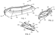
- the surfboard carrier 100 can include a left base 103 and a right base 104.
- the right base 103 or main base 103 and the left base 104 or sliding base 104 collectively constitute elongate base 102 and can be slidingly coupled to one another with one or both bases 103, 104 being capable of sliding.
- the main base 103 and sliding base 104 can be a single piece or can be multiple pieces.
- the surfboard carrier 100 can include an inner middle pad 106 and an outer middle pad 108.
- the inner middle pad 106 and the outer middle pad 108 can be a single piece or can be multiple pieces.
- the inner middle pad 106 and outer middle pad 108 can be coupled to, and together constitute a middle arm 110 or securement arm 110. Both of the inner middle pad 106 and outer middle pad 108 can be slidingly coupled to the middle arm 110.
- the surfboard carrier 100 can include a hinge 112 pivotally coupled at a first end 122 to the base 102 at a hinge-end 118 of the carrier 100.
- One end of a strap 114 can be coupled to the hinge 114 at an anchor end 120 of the strap 114.
- the strap 114 can be used to secure a surfing device (not shown) such as a surfboard or a wind surfing board or the like to the surfboard carrier 100.
- the surfboard carrier 100 can be in a transport position or locked position with the free end of the strap 114 secured to the right base 104.
- the base 102 can be configured with one or more upper support surfaces 116 enabled to receive a surfboard.
- FIGs. 2 and 3 left and right perspective views of the surfboard carrier with the hinge 112 in an extended position in accordance with an example embodiment, respectively, are illustrated.
- the hinge 112 can be extended upwards from the elongate base 102 allowing space for a surfing device (not shown) to reside between the middle pads 106, 108 and the base 102; e.g., the main base 103 and the sliding base 104.
- the upper support surfaces 116 of the base can include one or more pads having an engagement surface 200 configured to receive a surfboard.
- the hinge-end 118 of the carrier 100 can be coupled to a strap 114, the strap having a distal end 300 which can be passed through a locking mechanism on the base 102 in order to secure at least one surfboard to a vehicle.
- the sliding base 104 can be configured to adjustably slide away from the main base 103 to accommodate a surfing device (not shown).
- the outer middle pad 108 and inner middle pad 106 can also be separated to accommodate a surfing device (not shown).
- the sliding capability of the sliding base 104 and of the outer middle pad 108 can allow the surfboard carrier 100 to accommodate surfing devices having different widths.
- the sliding capability of the securement arm support pads 106, 108 can allow the surfboard carrier 100 to accommodate surfing devices having different widths and thicknesses.
- the surfboard carrier 100 can secure two surfing devices having the same or different widths and thicknesses.
- the surfboard carrier 100 can be a universal surf device carrier.
- a perspective view of a surfboard carrier coupled to a cross bar attached to a vehicle (not shown) in accordance with an example embodiment is illustrated.
- the surfboard carrier 100 can be coupled to one or more mounting feet 402 with each mounting foot 402 being coupled to a cross bar 404.
- a first surfboard carrier 100 can be coupled to a first cross bar 404 and a second surfboard carrier 100 can be coupled to a second cross bar 404.
- the strap can be releasably locked by a locking mechanism near a distal end 408 away from the hinge-end 118 of the carrier 100.
- Each of the mounting feet 402 can include a locking device (not shown) to lock the mounting foot 402 to a cross bar 404.
- the surfboard carrier 100 can be coupled directly to a cross bar 404.
- FIG. 5 a perspective view of a surfboard carrier securing two surfing devices in accordance with an example embodiment is illustrated.
- Fig. 5 represents an example of a transport or locked position or configuration of a carrier.
- a first surfing device 502 (surfboard shown as a partial view) can be secured on top of the elongate base 102 and a second surfing device 504 (shown as a partial view) can be secured on top of the securement arm 110.
- the first surfing device 502 can rest against an engagement surface 200 at the underside of the arm 110.
- the strap 114 can extend over the second surfing device 502 and can be coupled to the surfboard carrier 100 at a distal end 408 of the carrier 100.
- the surfboard carrier 100 can comprise an elongate base 102.
- a sliding base 104 can be slidingly coupled with a main base 103.
- one or both of the main base 103 and sliding base 104 can slide.
- neither base 103, 104 can slide.
- the main base 103 can comprise a tray 606 and extended walls 608.
- the tray 606 and extended walls 608 can be one piece or multiple pieces. Walls of the tray 606 can form a cavity 610.
- a base insert 612 can be inserted into the cavity 610 of the main base 103.
- the base insert 612 can include one or more detents 614 and a curved portion 616.
- the main base 103, sliding base 104, tray 606, extended walls 608, and base insert 612 can be made of, but not limited to, a hard plastic.
- the sliding base 104 can include extended side walls 618.
- the sliding base 104 can include a curved portion 620.
- the curved portions 616, 620 can conform to the shape of a surfing device.
- the curved portions 616, 620 can be configured to receive one or more base pads 622. As shown, there are four base pads; e.g., two base pads 622 for the main base 103 and two base pads 122 for the sliding base 104.
- Each base pad 622 can be made of, but not limited to, rubber or foam or other suitable material.
- Each base pad 622 can comprise an engagement surface 200 for engaging a surfboard.
- the base pads 622 and the curved portions 616, 620 can include male and female connectors to secure the base pads 622 to the corresponding curved portion 616, 620.
- Each base pad 622 can be coupled or fastened to a corresponding curved portion 616, 620 using one or more fasteners, such as but not limited to, screws or glue.
- the base pad 618 and curved portion 616 can be one piece.
- the extended walls 608, 618 and base pads 622 can be approximately the same height such that a surfing device can be supported evenly or substantially evenly on the base pads 622.
- a base button 624 can be pivotally coupled to the sliding base 104.
- the base button 624 can include a button channel 626 for receiving a button pin (not shown) which can be coupled to the extended walls 618 of the sliding base 104.
- the base button 624 can include one or more extending flanges 628 configured to be received in one or more corresponding detents 614 of the main base 103. When one or more of the extending flanges 628 of the base button 624 are received in one or more corresponding detents 614 of the main base 103, the sliding base 104 is locked in place and can no longer slide.
- the extending flanges 628 of the base button 624 can disconnect or unlock from one or more of the corresponding detents 614 of the main base 103 allowing the sliding base 104 to slide toward or away from the main base 103.
- the extending flanges 628 can comprise one or more detents configured to engage one or more indents in the main base 103 and thereby operate to releasably connect the sliding base 104 to the main base 103.
- the sliding base 104 can have a top surface (not shown) with the base button 624 being flush with the top surface.
- the detents 614 and base button 621 can be located on the other side; e.g., on the sliding base 104 and the main base 103, respectively. In one or more embodiments, other controllers for controlling the sliding of the main base 103 and sliding base 104 can be used.
- the sliding base 104 can include a locking portion 632.
- the locking portion 632 can comprise a lock 634 and strap restraining components.
- the lock 634 can include a lock cylinder housing 636 and a key 638 for locking the surfboard carrier 100.
- the lock cylinder housing 636 can be received, fully or partially, in a strap catch 640. If the lock cylinder housing 636 is only partially received in the strap catch 640, the rest of the lock cylinder housing 636 can be received within the sliding base 104 and/or in the locking portion 632 of the sliding base 104.
- the strap catch 640 can be pivotally coupled to a side of the sliding base 104.
- the strap catch 640 can include a pin channel 642 at about one distal end to receive a lock pin (not shown) to pivotally couple the strap catch 640 to the sliding base 104.
- a lock pin (not shown) to pivotally couple the strap catch 640 to the sliding base 104.
- the strap catch 640 In the locked position, the strap catch 640 can be flush with the side of the sliding base 104.
- the strap catch 640 In the unlocked position, the strap catch 640 can pivot away from the side of the sliding base 104.
- the other end of the strap catch 640 e.g., the end opposite the end with the pin channel 642, can include a strap door flange 642.
- the strap door flange 642 can assist in securing a strap door 644 when the strap catch 640 is in the locked position.
- the strap door 644 can include an extended end 646 at about one distal end.
- the extended end 646 and strap door flange 642 can interact securing the strap door 644 to the locking portion 632 of the sliding base 104.
- a strap door channel 648 can be included for pivotally connecting the strap door 644 to the locking portion 632 of the sliding base 104 via a pin (not shown).
- the strap door 644 can be pivotally coupled to the side or end of the locking portion 632 of the sliding base 104. In the locked position, the strap door 644 can be flush with the locking portion 632 of the sliding base 104. In the unlocked position, the strap door 644 can pivot away from the end of the locking portion 632 of the sliding base 104.
- the locking portion 632 can include a strap cam 650.
- the strap cam 650 can be coupled to the locking portion 632; e.g., in an indent 652 formed in the locking portion 632.
- One or more cam flanges 654 or teeth can be on a surface of the strap cam 650.
- the one or more cam flanges 654 can assist in securing a strap 114.
- the strap 114 can be placed in the indent 652 of the locking portion 632 and when the strap door 644 is in the locked position, friction can assist in securing the strap 114 against the cam flanges 654, "locking" or securing the strap 114 in place.
- the sliding base 104 can include a plate 630 coupled to the bottom of the sliding base 104.
- One or more fasteners can couple or fasten the plate 630 to the bottom of the sliding base 104.
- the plate 630 can include a retaining component (not shown) to assist in retaining the strap 114.
- other locking systems can be used to lock the strap 114 in place and prevent unauthorized access to the strap 114.
- the locking portion 632 can include a cap 658 to cover the locking portion 632.
- the cap 658 can assist in preventing foreign matter, such as dirt, from entering the locking portion 632.
- the cap 658 can form a strap receiving portion 660 to allow the strap 114 to rest on (and/or guide the strap 114) the strap receiving portion 660.
- the cap 658 can include mating components configured to interact with mating components on the locking portion 632 to secure the cap 658 to the locking portion 632. In one or more embodiments, other fasteners, including but not limited to, screws or glue, can be used to secure the cap 658 to the locking portion 632.
- the locking portion 632 and cap 658 can be made of, but not limited to, a hard plastic.
- the locking cylinder housing 636, key 638, strap catch 640, strap door flange 642, strap door 644, extended end 646, and strap cam 650 can be made of, but not limited to, steel or hard metal.
- the surfboard carrier 100 can include a bottom hinge 662 pivotally coupled to the main base 103.
- the bottom hinge 662 e.g. 112
- the extended walls 618 of the main base 103 can include apertures 666 to receive a connector 668 to couple the bottom hinge 662 to the main base 103.
- the apertures 664 of the bottom hinge 662 can be located proximate opposite, distal ends of the bottom hinge 662.
- the bottom hinge 662 can be made of, but is not limited to, a hard plastic.
- the connector 668 can be, but is not limited to a rod, a spring, pins, or a combination thereof.
- a reinforcing member 670 such as a u-shaped metal stamping, can be used to assist in securing the bottom hinge 662 to the main base 103.
- the reinforcing member 670 can include apertures 672 to receive the connector 668.
- a middle arm 674 can be fixedly coupled.
- a pin (not shown) can fasten the middle arm 674 (e.g. 110) or securement arm 674 (e.g. 110) to the bottom hinge 662.
- the bottom hinge 662 can pivot in several positions including a transport position and an extended position.
- the middle arm 674 can be made of, but is not limited to, a hard plastic.
- the bottom hinge 662 In the transport position, the bottom hinge 662 can be in a lowered position e.g., with the middle arm 674 in a horizontal or near horizontal position with respect to the main base 103 and sliding base 104.
- the bottom hinge 662 In the extended position, the bottom hinge 662 can be in a raised position; e.g., with the middle arm 674 in a vertical or near vertical position with respect to the main base 103 and sliding base 104.
- the bottom hinge 662 can remain in a particular configuration; e.g., locked in place.
- the bottom hinge 662 can pivot; e.g., unlocked.
- the bottom hinge 662 and the middle arm 674 can be one or more multiple pieces.
- One end of strap 114 can be fixedly coupled to the bottom hinge 662 or to the main base 103.
- the other end of the strap 114 can be inserted into or through the locking portion 632.
- the other end of the strap 114 e.g., the end not coupled to the bottom hinge 662, can include a restraining device (not shown) which prevents the strap 114 from detaching from the locking portion 632.
- the restraining device of the strap 114 can interact with the restraining component of the plate 630 to prevent the strap 114 from disconnecting from the surfboard carrier 100.
- the strap 114 can be made of, but is not limited to, nylon, and can include a steel cable covered by the material; e.g., nylon.
- the bottom hinge 662 can include an upper hinge pad 676.
- the bottom surface of the upper hinge pad 676 can conform to the shape of a surfing device.
- the bottom surface of the upper hinge pad 676 can be made of, but not limited to, rubber or foam.
- the rest of the upper hinge pad 676 can be made of, but not limited to, a hard plastic.
- One or more pads can be coupled to the middle arm 674.
- middle pads 678, 680 are slidingly coupled to the middle arm 676.
- one or both of the middle pads 678, 680 can slide.
- neither middle pad 678, 680 can slide.
- the middle pads 678, 680 can slide toward or away from each other to accommodate a surfing device (not shown).
- the sliding capability of the middle pads 678, 680 can allow the surfboard carrier 100 to accommodate surfing devices having different widths.
- the top portions of the fixed middle pad 678 and of the sliding middle pad 680 can conform to the shape of a surfing device.
- the top portions of the middle pads 678, 680 can form one or more channels 682 to receive the strap 114.
- the bottom portions of the middle pads 678, 680 can have various shapes, including but not limited to, substantially flat, or have one or more protrusions to assist in securing the surfing device in place.
- each middle pad 678, 680 is one piece, however in one or more embodiments, each middle pad 678, 680 can be multiple pieces and can be coupled to the middle arm 674 using various coupling means.
- Each middle pad 678, 680 can be made of, but not limited to, rubber or foam.
- FIG. 6A a top plan view of a surfboard carrier 100 in accordance with an example embodiment is illustrated.
- a base button is shown within a button channel 626 in the sliding base 104.
- Base pad engagement surfaces 200 are coupled to the sliding base 104 and the elongate base 104.
- An end 300 of the strap is shown in a channel on the securement arm 110.
- the bottoms of the pads on the securement arm 110 have engagement surfaces 692 which can engage the surface of a surfboard when the surfboard carrier 100 is in a closed configuration.
- FIG. 6B a cutaway view of a surfboard carrier 100 in accordance with an example embodiment is illustrated.
- An example of an interconnection 686 between a support pad and a base is depicted.
- a pad can be configured with male connectors corresponding with female connectors in a base.
- a pad can comprise a tongue 688 running along a substantial length of the pad configured to be received by a corresponding groove 690 in the base.
- Fig. 6C illustrates a detailed view of the base illustrated in Fig. 6B , showing the location of grooves 690 within the base configured to receive a tongue 688 of a pad.
- Fig. 6D illustrates a see-through view of the surfboard carrier 100 illustrated in Fig. 6A , depicting the relationship between support pads 622 and receiving portions of the base 102, 104.
- the alternate surfboard carrier 700 of Fig. 7 is similar to the surfboard carrier 100 of Fig. 1 and Fig. 6 and includes a different means to secure a second surfing device to the surfboard carrier 700.
- the surfboard carrier 700 can include a top arm 702.
- Atop hinge 704 can be coupled to the top arm 702 at one end and can be coupled to the bottom hinge 662 at the other end.
- the top arm 702 and top hinge 704 can be made of, but not limited to, a hard plastic.
- the top arm 702 can include a top arm pad 706 on the bottom surface of the top arm 702.
- the top arm pad 706 can be made of, but not limited to, rubber or foam.
- the surfboard carrier 700 is in a transport position.
- the bottom hinge 662 can be in a lowered position; e.g., with the middle arm 674 in a horizontal or near horizontal position with respect to the main base 103 and sliding base 104 and the top hinge 704 can be in a lowered position; e.g., with the top arm 702 in a horizontal or near horizontal position with respect to the middle arm 674.
- the top hinge 704 In an extended position, can be in a raised position; e.g., with the top arm 702 in a vertical or near vertical position with respect to the main base 103 and sliding base 104.
- the top hinge 704 can remain in place; e.g., be locked in place.
- the top hinge 662 can pivot; e.g., be unlocked.
- the top hinge 704 and the top arm 702 can be one or more multiple pieces.
- a strap (not shown) can be fixedly coupled to the top hinge 704 or to the top arm 702.
- one end of the strap can be fixedly coupled to the top arm 702 and can be covered by the top arm pad 706.
- the strap can be made from a material, such as, but not limited to, nylon, and can include a steel cable covered by the material.
- the top hinge 704 can include a top hinge pad (not shown).
- the bottom surface of the top hinge pad can conform to the shape of a surfing device.
- the bottom surface of the top hinge pad can be made of, but not limited to, rubber or foam.
- the rest of the top hinge pad e.g., not the bottom surface, can be made of, but not limited to a hard plastic.
- a surfing device e.g., 802 (shown as a partial view) is secured on top of the main base 103 and the sliding base 104.
- the top hinge 704 is in the transport position and the bottom hinge 662 is in the extended position.
- the middle arm 676 includes a different middle pad compared to the middle pads 678, 680 shown in Fig. 6 .
- a partial strap 804 is shown as being locked in the locking portion 632.
- the top arm 702 can extend over the middle arm 674 and a strap 804 can be coupled to the surfboard carrier 800.
- a perspective view of the alternate surfboard carrier securing two surfing devices in accordance with an example embodiment is illustrated.
- a first surfing device 902 (shown as a partial view) can be secured on top of the main base 103 and the sliding base 104 and a second surfing device 904 (shown as a partial view) can be secured on top of a middle pad.
- the top hinge 704 is in the extended position and the bottom hinge 662 is in the extended position.
- the middle arm 676 includes a different middle pad compared to the middle pads 678, 680 shown in Fig. 6 .
- a partial strap 804 is shown as being locked in the locking portion 632.
- the top arm 702 can extend over the second surfing device 502 and the strap 804 can be coupled to the surfboard carrier 900.
- FIG. 10 a perspective view of two surfboard carriers installed on a vehicle in accordance with an example embodiment is illustrated.
- the example carriers 100 are each in an installed orientation 1000.
- the straps are coupled at a hinge-end 118 of the carrier.
- the carriers are in unlocked positions because the ends 300 of the straps have not been passed through a locking mechanism on the carrier 100.
- FIG. 11 a perspective view of a surfboard carrier in accordance with an example embodiment is illustrated.
- An anchor end 120 of a strap 114 is coupled to a hinge-end 118 of carrier 100.
- a portion of the strap is contained within sheaths 1102.
- the sheaths 1102 can be adjustably slid along the strap 114 in order to accommodate different sized surfboards just as upper support pads can be slid along the securement arm 110 and the sliding base 104 can be slid along the main base 103.
- Sheaths 1102 can be made of soft plastic or rubber or other suitable material. Sheaths 1102 can enable the strap 114 to better retain a surfboard placed on the securement arm 110 when the carrier 100 is in a locked configuration 500.
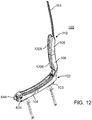
- FIG. 12 a perspective view of a surfboard carrier in an open configuration in accordance with an example embodiment is illustrated.
- the upper pads 106, 108 or middle pads 106, 108 or securement pads 106, 108 comprise raised engagement portions 1206, 1208.
- Raised engagement portions 1206, 1208 are configured to engage the surface of a surfboard and can enable the securement arm 110 to better secure a surfboard beneath the securement arm 110 when the surfboard carrier 100 is in a transportation configuration.
- a surfboard carrier is a variably configurable surfboard carrier 100 adapted to be mounted on a carrying vehicle.
- the surfboard carrier 100 can comprise an elongate base 102 having a longitudinal axis and configured to receive a surfboard upon an upper support surface 116 of the base 102.
- the base 102 can be approximately horizontally oriented when in an installed orientation 1000.
- the surfboard carrier 100 can also comprise a surfboard securement arm 110, 674 which has a longitudinal axis.
- the securement arm 110, 674 can be coupled to the elongate base 102 and can be placed in multiple positions relative to the base 102 on a displacement hinge 112 that accommodates variable location and orientation of the securement arm 110, 674 relative to the base 102.
- the displacement hinge 112 can have an elongate extension body 662 having a first end 122 which is pivotally coupled to the base 102, and an opposite distal end 684 pivotally coupled to the securement arm 110, 674 or middle arm.
- the surfboard carrier 100 has a first transport configuration for supporting and securing a surfboard of a first thickness between the base 102 and securement arm 110, 674 wherein the longitudinal axis of the securement arm 110, 674 is located at a first distance above the base 102 and is oriented approximately parallel to the longitudinal axis of the base 102 and a second transport configuration for supporting and securing a surfboard of a second thickness, which is greater than the first thickness, between the base 102 and securement arm 110, 674 wherein the longitudinal axis of the securement arm 110, 674 is located at a second distance, greater than the first distance, above the base 102 and is oriented approximately parallel to the longitudinal axis of the base 102.
- the elongate base 102 has a longitudinal axis 722 that is coincident with an x-axis of a three-dimensional Cartesian coordinate system of the base 102 that has its origin located at the centroid 721 of the base 102. As illustrated, the centroid 721 is located mid-length, mid-width and mid-height of the base 102, where each is measured from opposite extreme exterior surfaces of the base 102.
- the longitudinal axis 722 of the base 102 is approximately horizontally oriented (within fifteen degrees or horizontal) in the installed orientation 1000 depicted in Figs.
- a surfboard securement arm 110, 674 is shown that has a longitudinal axis 742 that is coincident with an x-axis of a three-dimensional Cartesian coordinate system of the securement arm 110, 674 and that has its origin located at the centroid 741 of the securement arm 110, 674 defined as described above with respect to the base 102.
- the longitudinal axis 742 of the securement arm 110, 674 is similarly approximately horizontally oriented (within fifteen degrees or horizontal) in the installed orientation 1000 of Figs.
- At least one example embodiment of a surfboard carrier 100 comprises an elongate base 102 having a longitudinal axis and a plurality of support pads 622 mounted on the elongate base 102.
- Each pad 622 can include an engagement surface 200 configured for abutting engagement with a surfboard.
- At least one of the plurality of support pads 622 can be slidingly coupled to the elongate base 102 and lengthwise laterally translatable upon the elongate base for accommodating different sized surfboards.
- At least one example embodiment of a surfboard carrier 100 comprises a securement strap 114 coupled to an elongate base 102, a securement arm 110, 674 or a hinge 112 at a hinge-end 118 of the carrier 100 by an anchor end 120 of the strap 114.
- a distal end of the securement strap 114 can be releasably lockable at a distal end 408 of the carrier 100, opposite the hinge-end 118, to the base 102 or the arm 110, 674 or the base 102 and the arm 110, 674, for securing a surfboard atop the securement arm 110, 674 in a locked configuration 500 of the carrier 100.
- Example implementations have been described hereinabove regarding various example embodiments of a variably configurable surfboard carrier.
- the example embodiments are intended to constitute non-limiting examples.
- the subject matter that is intended to be within this disclosure is set forth in the following claims.
Abstract
Description
- The present disclosure relates generally to a locking surfboard carrier. More specifically, the present disclosure relates to a locking surfboard carrier for transporting one or more water sport board devices such as surfboards, parasail boards and the like.
- Safely transporting sports gear is a concern for many sport enthusiasts. For example, transporting a surfboard in a trunk raises many safety concerns. In the event that the surfboard falls out of the trunk, not only can the surfboard be damaged, but the surfboard can cause bodily harm or property damage as vehicles attempt to avoid the fallen surfboard. In addition, security of the surfboard can be an issue in that the surfboard may be stolen from an open trunk of a vehicle.
- Implementations of the present application will now be described, by way of example only, with reference to the attached figures, wherein:
-
Fig. 1 is a perspective view of a surfboard carrier in accordance with an example embodiment; -
Fig. 2 is a left side perspective view showing a bottom hinge of a surfboard carrier in accordance with an example embodiment; -
Fig. 3 is a right side perspective view showing a bottom hinge of a surfboard carrier in accordance with an example embodiment; -
Fig. 4 is a perspective view of a surfboard carrier coupled to a cross bar in accordance with an example embodiment; -
Fig. 5 is a perspective view of a surfboard carrier securing two surfing devices in accordance with an example embodiment; -
Fig. 6 is an exploded view of a surfboard carrier in accordance with an example embodiment; -
Fig. 6A is a top plan view of a surfboard carrier in accordance with an example embodiment; -
Fig. 6B is a cut away view of a surfboard carrier in accordance with an example embodiment; -
Fig. 6C is a detailed view of a surfboard carrier in accordance with an example embodiment; -
Fig. 6D is a cut away view of a surfboard carrier in accordance with an example embodiment; -
Fig. 7 is a perspective view of a surfboard carrier in accordance with an example embodiment; -
Fig. 8 is a perspective view of a surfboard carrier securing a single surfboard in accordance with an example embodiment; -
Fig. 9 is a perspective view of a surfboard carrier securing two surfing devices in accordance with an example embodiment; -
Fig. 10 is a perspective view of two surfboard carriers attached to a vehicle in accordance with an example embodiment; -
Fig. 11 is a perspective view of a surfboard carrier in accordance with an example embodiment; -
Fig. 12 is a perspective view of a surfboard carrier in an open configuration in accordance with an example embodiment; and -
Fig. 13 is a side view of a surfboard carrier in an open configuration in accordance with an example embodiment. - It will be appreciated that for simplicity and clarity of illustration, where appropriate, reference numerals have been repeated among the different figures to indicate corresponding or analogous elements. In addition, numerous specific details are set forth in order to provide a thorough understanding of the implementations described herein. However, it will be understood by those of ordinary skill in the art that the implementations described herein can be practiced without these specific details. In other instances, methods, procedures and components have not been described in detail so as not to obscure the related relevant function being described. Also, the description is not to be considered as limiting the scope of the implementations described herein.
- Generally speaking, the surf carriers of the various example embodiments described herein have a base with one or more pads on which a first water sport board device (generically referred to herein as "surfboard") can rest on top of the one or more pads, a middle arm having one or more pads on a top surface and one or more pads on the bottom surface in which a second surfing device can rest on top of the one or more pads on the top surface of the middle arm, and a strap coupled to the base; e.g., via a hinge, with the strap securing the first surfing device and the second surfing device to the base. The strap can be locked to the base, thereby securing one or more surfing devices and preventing unauthorized access to the one or more surfing devices.
- Referring to
Fig. 1 , a perspective view of a surfboard carrier in accordance with an example implementation is illustrated. As shown, thesurfboard carrier 100 can include aleft base 103 and aright base 104. Theright base 103 ormain base 103 and theleft base 104 or slidingbase 104 collectively constituteelongate base 102 and can be slidingly coupled to one another with one or bothbases main base 103 andsliding base 104 can be a single piece or can be multiple pieces. Thesurfboard carrier 100 can include aninner middle pad 106 and anouter middle pad 108. In one or more embodiments, theinner middle pad 106 and theouter middle pad 108 can be a single piece or can be multiple pieces. Theinner middle pad 106 andouter middle pad 108 can be coupled to, and together constitute amiddle arm 110 or securementarm 110. Both of theinner middle pad 106 andouter middle pad 108 can be slidingly coupled to themiddle arm 110. - The
surfboard carrier 100 can include ahinge 112 pivotally coupled at a first end 122 to thebase 102 at a hinge-end 118 of thecarrier 100. One end of astrap 114 can be coupled to thehinge 114 at ananchor end 120 of thestrap 114. Thestrap 114 can be used to secure a surfing device (not shown) such as a surfboard or a wind surfing board or the like to thesurfboard carrier 100. As shown inFig. 1 , thesurfboard carrier 100 can be in a transport position or locked position with the free end of thestrap 114 secured to theright base 104. Thebase 102 can be configured with one or more upper support surfaces 116 enabled to receive a surfboard. - Referring to
Figs. 2 and 3 , left and right perspective views of the surfboard carrier with thehinge 112 in an extended position in accordance with an example embodiment, respectively, are illustrated. As shown, thehinge 112 can be extended upwards from theelongate base 102 allowing space for a surfing device (not shown) to reside between themiddle pads base 102; e.g., themain base 103 and thesliding base 104. The upper support surfaces 116 of the base can include one or more pads having an engagement surface 200 configured to receive a surfboard. The hinge-end 118 of thecarrier 100 can be coupled to astrap 114, the strap having adistal end 300 which can be passed through a locking mechanism on thebase 102 in order to secure at least one surfboard to a vehicle. As shown in these figures, thesliding base 104 can be configured to adjustably slide away from themain base 103 to accommodate a surfing device (not shown). Similarly, theouter middle pad 108 andinner middle pad 106 can also be separated to accommodate a surfing device (not shown). The sliding capability of thesliding base 104 and of theouter middle pad 108 can allow thesurfboard carrier 100 to accommodate surfing devices having different widths. Similarly, the sliding capability of the securementarm support pads surfboard carrier 100 to accommodate surfing devices having different widths and thicknesses. As a result, thesurfboard carrier 100 can secure two surfing devices having the same or different widths and thicknesses. Hence, thesurfboard carrier 100 can be a universal surf device carrier. - Referring to
Fig. 4 , a perspective view of a surfboard carrier coupled to a cross bar attached to a vehicle (not shown) in accordance with an example embodiment is illustrated. As shown, thesurfboard carrier 100 can be coupled to one or more mountingfeet 402 with each mountingfoot 402 being coupled to across bar 404. In use, afirst surfboard carrier 100 can be coupled to afirst cross bar 404 and asecond surfboard carrier 100 can be coupled to asecond cross bar 404. When securing a surfboard, the strap can be releasably locked by a locking mechanism near adistal end 408 away from the hinge-end 118 of thecarrier 100. Each of the mountingfeet 402 can include a locking device (not shown) to lock the mountingfoot 402 to across bar 404. In one or more embodiments, thesurfboard carrier 100 can be coupled directly to across bar 404. - Referring to
Fig. 5 , a perspective view of a surfboard carrier securing two surfing devices in accordance with an example embodiment is illustrated.Fig. 5 represents an example of a transport or locked position or configuration of a carrier. As shown, a first surfing device 502 (surfboard shown as a partial view) can be secured on top of theelongate base 102 and a second surfing device 504 (shown as a partial view) can be secured on top of thesecurement arm 110. Thefirst surfing device 502 can rest against an engagement surface 200 at the underside of thearm 110. Thestrap 114 can extend over thesecond surfing device 502 and can be coupled to thesurfboard carrier 100 at adistal end 408 of thecarrier 100. - Referring to
Fig. 6 , an exploded view of the surfboard carrier in accordance with an example embodiment is illustrated. As shown, thesurfboard carrier 100 can comprise anelongate base 102. A slidingbase 104 can be slidingly coupled with amain base 103. In one or more embodiments, one or both of themain base 103 and slidingbase 104 can slide. In yet other embodiments, neitherbase main base 103 can comprise atray 606 and extendedwalls 608. Thetray 606 and extendedwalls 608 can be one piece or multiple pieces. Walls of thetray 606 can form acavity 610. Abase insert 612 can be inserted into thecavity 610 of themain base 103. One or more fasteners, including but not limited to, screws or glue, can couple or fasten the insert to themain base 103. Thebase insert 612 can include one ormore detents 614 and acurved portion 616. Themain base 103, slidingbase 104,tray 606, extendedwalls 608, andbase insert 612 can be made of, but not limited to, a hard plastic. - The sliding
base 104 can include extendedside walls 618. The slidingbase 104 can include acurved portion 620. Thecurved portions curved portions more base pads 622. As shown, there are four base pads; e.g., twobase pads 622 for themain base 103 and two base pads 122 for the slidingbase 104. Eachbase pad 622 can be made of, but not limited to, rubber or foam or other suitable material. Eachbase pad 622 can comprise an engagement surface 200 for engaging a surfboard. Thebase pads 622 and thecurved portions base pads 622 to the correspondingcurved portion base pad 622 can be coupled or fastened to a correspondingcurved portion base pad 618 andcurved portion 616 can be one piece. Theextended walls base pads 622 can be approximately the same height such that a surfing device can be supported evenly or substantially evenly on thebase pads 622. - A
base button 624 can be pivotally coupled to the slidingbase 104. For example, thebase button 624 can include abutton channel 626 for receiving a button pin (not shown) which can be coupled to theextended walls 618 of the slidingbase 104. Thebase button 624 can include one or more extendingflanges 628 configured to be received in one or morecorresponding detents 614 of themain base 103. When one or more of the extendingflanges 628 of thebase button 624 are received in one or morecorresponding detents 614 of themain base 103, the slidingbase 104 is locked in place and can no longer slide. When thebase button 624 is pressed, the extendingflanges 628 of thebase button 624 can disconnect or unlock from one or more of the correspondingdetents 614 of themain base 103 allowing the slidingbase 104 to slide toward or away from themain base 103. In one or more embodiments, the extendingflanges 628 can comprise one or more detents configured to engage one or more indents in themain base 103 and thereby operate to releasably connect the slidingbase 104 to themain base 103. In one or more embodiments, the slidingbase 104 can have a top surface (not shown) with thebase button 624 being flush with the top surface. In one or more embodiments, thedetents 614 and base button 621 can be located on the other side; e.g., on the slidingbase 104 and themain base 103, respectively. In one or more embodiments, other controllers for controlling the sliding of themain base 103 and slidingbase 104 can be used. - The sliding
base 104 can include a lockingportion 632. The lockingportion 632 can comprise alock 634 and strap restraining components. Thelock 634 can include alock cylinder housing 636 and a key 638 for locking thesurfboard carrier 100. Thelock cylinder housing 636 can be received, fully or partially, in astrap catch 640. If thelock cylinder housing 636 is only partially received in thestrap catch 640, the rest of thelock cylinder housing 636 can be received within the slidingbase 104 and/or in the lockingportion 632 of the slidingbase 104. Thestrap catch 640 can be pivotally coupled to a side of the slidingbase 104. For example, thestrap catch 640 can include apin channel 642 at about one distal end to receive a lock pin (not shown) to pivotally couple thestrap catch 640 to the slidingbase 104. In the locked position, thestrap catch 640 can be flush with the side of the slidingbase 104. In the unlocked position, thestrap catch 640 can pivot away from the side of the slidingbase 104. The other end of thestrap catch 640; e.g., the end opposite the end with thepin channel 642, can include astrap door flange 642. Thestrap door flange 642 can assist in securing astrap door 644 when thestrap catch 640 is in the locked position. Thestrap door 644 can include anextended end 646 at about one distal end. Theextended end 646 andstrap door flange 642 can interact securing thestrap door 644 to the lockingportion 632 of the slidingbase 104. At the opposite end of thestrap door 644; e.g., the end opposite theextended end 646, a strap door channel 648 can be included for pivotally connecting thestrap door 644 to the lockingportion 632 of the slidingbase 104 via a pin (not shown). Thestrap door 644 can be pivotally coupled to the side or end of the lockingportion 632 of the slidingbase 104. In the locked position, thestrap door 644 can be flush with the lockingportion 632 of the slidingbase 104. In the unlocked position, thestrap door 644 can pivot away from the end of the lockingportion 632 of the slidingbase 104. - The locking
portion 632 can include astrap cam 650. Thestrap cam 650 can be coupled to the lockingportion 632; e.g., in anindent 652 formed in the lockingportion 632. One ormore cam flanges 654 or teeth can be on a surface of thestrap cam 650. The one ormore cam flanges 654 can assist in securing astrap 114. For example, thestrap 114 can be placed in theindent 652 of the lockingportion 632 and when thestrap door 644 is in the locked position, friction can assist in securing thestrap 114 against thecam flanges 654, "locking" or securing thestrap 114 in place. The slidingbase 104 can include aplate 630 coupled to the bottom of the slidingbase 104. One or more fasteners, including but not limited to, screws and glue, can couple or fasten theplate 630 to the bottom of the slidingbase 104. Theplate 630 can include a retaining component (not shown) to assist in retaining thestrap 114. In one or more embodiments, other locking systems can be used to lock thestrap 114 in place and prevent unauthorized access to thestrap 114. - The locking
portion 632 can include acap 658 to cover the lockingportion 632. Thecap 658 can assist in preventing foreign matter, such as dirt, from entering the lockingportion 632. Thecap 658 can form astrap receiving portion 660 to allow thestrap 114 to rest on (and/or guide the strap 114) thestrap receiving portion 660. Thecap 658 can include mating components configured to interact with mating components on the lockingportion 632 to secure thecap 658 to the lockingportion 632. In one or more embodiments, other fasteners, including but not limited to, screws or glue, can be used to secure thecap 658 to the lockingportion 632. The lockingportion 632 andcap 658 can be made of, but not limited to, a hard plastic. The lockingcylinder housing 636, key 638,strap catch 640,strap door flange 642,strap door 644,extended end 646, andstrap cam 650 can be made of, but not limited to, steel or hard metal. - The
surfboard carrier 100 can include abottom hinge 662 pivotally coupled to themain base 103. For example, the bottom hinge 662 (e.g. 112) can includeapertures 664 and theextended walls 618 of themain base 103 can includeapertures 666 to receive aconnector 668 to couple thebottom hinge 662 to themain base 103. Theapertures 664 of thebottom hinge 662 can be located proximate opposite, distal ends of thebottom hinge 662. Thebottom hinge 662 can be made of, but is not limited to, a hard plastic. Theconnector 668 can be, but is not limited to a rod, a spring, pins, or a combination thereof. A reinforcingmember 670, such as a u-shaped metal stamping, can be used to assist in securing thebottom hinge 662 to themain base 103. The reinforcingmember 670 can includeapertures 672 to receive theconnector 668. At the other distal end of thebottom hinge 662; e.g., the end opposite the distal end 122 with theapertures 664, amiddle arm 674 can be fixedly coupled. For example, a pin (not shown) can fasten the middle arm 674 (e.g. 110) or securement arm 674 (e.g. 110) to thebottom hinge 662. Thebottom hinge 662 can pivot in several positions including a transport position and an extended position. - The
middle arm 674 can be made of, but is not limited to, a hard plastic. In the transport position, thebottom hinge 662 can be in a lowered position e.g., with themiddle arm 674 in a horizontal or near horizontal position with respect to themain base 103 and slidingbase 104. In the extended position, thebottom hinge 662 can be in a raised position; e.g., with themiddle arm 674 in a vertical or near vertical position with respect to themain base 103 and slidingbase 104. Using one or more detents (not shown) and one or more springs (not shown), thebottom hinge 662 can remain in a particular configuration; e.g., locked in place. By applying pressure to themiddle arm 674, thebottom hinge 662 can pivot; e.g., unlocked. In one or more embodiments, thebottom hinge 662 and themiddle arm 674 can be one or more multiple pieces. One end ofstrap 114 can be fixedly coupled to thebottom hinge 662 or to themain base 103. The other end of thestrap 114 can be inserted into or through the lockingportion 632. In one or more embodiments, the other end of thestrap 114; e.g., the end not coupled to thebottom hinge 662, can include a restraining device (not shown) which prevents thestrap 114 from detaching from the lockingportion 632. For example, the restraining device of thestrap 114 can interact with the restraining component of theplate 630 to prevent thestrap 114 from disconnecting from thesurfboard carrier 100. Thestrap 114 can be made of, but is not limited to, nylon, and can include a steel cable covered by the material; e.g., nylon. Thebottom hinge 662 can include anupper hinge pad 676. The bottom surface of theupper hinge pad 676 can conform to the shape of a surfing device. The bottom surface of theupper hinge pad 676 can be made of, but not limited to, rubber or foam. The rest of theupper hinge pad 676 can be made of, but not limited to, a hard plastic. - One or more pads can be coupled to the
middle arm 674. As shown,middle pads 678, 680 are slidingly coupled to themiddle arm 676. In one or more embodiments, one or both of themiddle pads 678, 680 can slide. In yet other embodiments, neithermiddle pad 678, 680 can slide. Themiddle pads 678, 680 can slide toward or away from each other to accommodate a surfing device (not shown). The sliding capability of themiddle pads 678, 680 can allow thesurfboard carrier 100 to accommodate surfing devices having different widths. The top portions of the fixed middle pad 678 and of the slidingmiddle pad 680 can conform to the shape of a surfing device. The top portions of themiddle pads 678, 680 can form one ormore channels 682 to receive thestrap 114. The bottom portions of themiddle pads 678, 680 can have various shapes, including but not limited to, substantially flat, or have one or more protrusions to assist in securing the surfing device in place. As shown, eachmiddle pad 678, 680 is one piece, however in one or more embodiments, eachmiddle pad 678, 680 can be multiple pieces and can be coupled to themiddle arm 674 using various coupling means. Eachmiddle pad 678, 680 can be made of, but not limited to, rubber or foam. - Referring to
Fig. 6A , a top plan view of asurfboard carrier 100 in accordance with an example embodiment is illustrated. A base button is shown within abutton channel 626 in the slidingbase 104. Base pad engagement surfaces 200 are coupled to the slidingbase 104 and theelongate base 104. Anend 300 of the strap is shown in a channel on thesecurement arm 110. The bottoms of the pads on thesecurement arm 110 have engagement surfaces 692 which can engage the surface of a surfboard when thesurfboard carrier 100 is in a closed configuration. - Referring to
Fig. 6B , a cutaway view of asurfboard carrier 100 in accordance with an example embodiment is illustrated. An example of aninterconnection 686 between a support pad and a base is depicted. A pad can be configured with male connectors corresponding with female connectors in a base. A pad can comprise atongue 688 running along a substantial length of the pad configured to be received by acorresponding groove 690 in the base.Fig. 6C illustrates a detailed view of the base illustrated inFig. 6B , showing the location ofgrooves 690 within the base configured to receive atongue 688 of a pad.Fig. 6D illustrates a see-through view of thesurfboard carrier 100 illustrated inFig. 6A , depicting the relationship betweensupport pads 622 and receiving portions of thebase - Referring to
Fig. 7 , a perspective view of an alternate surfboard carrier in accordance with an example embodiment is illustrated. Thealternate surfboard carrier 700 ofFig. 7 is similar to thesurfboard carrier 100 ofFig. 1 andFig. 6 and includes a different means to secure a second surfing device to thesurfboard carrier 700. As shown, thesurfboard carrier 700 can include atop arm 702. Atophinge 704 can be coupled to thetop arm 702 at one end and can be coupled to thebottom hinge 662 at the other end. Thetop arm 702 andtop hinge 704 can be made of, but not limited to, a hard plastic. Thetop arm 702 can include atop arm pad 706 on the bottom surface of thetop arm 702. Thetop arm pad 706 can be made of, but not limited to, rubber or foam. As shown, thesurfboard carrier 700 is in a transport position. In the transport position, thebottom hinge 662 can be in a lowered position; e.g., with themiddle arm 674 in a horizontal or near horizontal position with respect to themain base 103 and slidingbase 104 and thetop hinge 704 can be in a lowered position; e.g., with thetop arm 702 in a horizontal or near horizontal position with respect to themiddle arm 674. In an extended position, thetop hinge 704 can be in a raised position; e.g., with thetop arm 702 in a vertical or near vertical position with respect to themain base 103 and slidingbase 104. Using one or more detents (not shown) and one or more springs (not shown), thetop hinge 704 can remain in place; e.g., be locked in place. By applying pressure to themiddle arm 674, thetop hinge 662 can pivot; e.g., be unlocked. - In one or more embodiments, the
top hinge 704 and thetop arm 702 can be one or more multiple pieces. A strap (not shown) can be fixedly coupled to thetop hinge 704 or to thetop arm 702. For example, one end of the strap can be fixedly coupled to thetop arm 702 and can be covered by thetop arm pad 706. The strap can be made from a material, such as, but not limited to, nylon, and can include a steel cable covered by the material. Thetop hinge 704 can include a top hinge pad (not shown). The bottom surface of the top hinge pad can conform to the shape of a surfing device. The bottom surface of the top hinge pad can be made of, but not limited to, rubber or foam. The rest of the top hinge pad, e.g., not the bottom surface, can be made of, but not limited to a hard plastic. - Referring to
Fig. 8 , a perspective view of the alternate surfboard carrier securing a single surfing device in accordance with an example embodiment is illustrated. As shown, a surfing device; e.g., 802, (shown as a partial view) is secured on top of themain base 103 and the slidingbase 104. As shown, thetop hinge 704 is in the transport position and thebottom hinge 662 is in the extended position. In this figure, themiddle arm 676 includes a different middle pad compared to themiddle pads 678, 680 shown inFig. 6 . Apartial strap 804 is shown as being locked in the lockingportion 632. Thetop arm 702 can extend over themiddle arm 674 and astrap 804 can be coupled to the surfboard carrier 800. - Referring to
Fig. 9 , a perspective view of the alternate surfboard carrier securing two surfing devices in accordance with an example embodiment is illustrated. As shown, a first surfing device 902 (shown as a partial view) can be secured on top of themain base 103 and the slidingbase 104 and a second surfing device 904 (shown as a partial view) can be secured on top of a middle pad. As shown, thetop hinge 704 is in the extended position and thebottom hinge 662 is in the extended position. In this figure, themiddle arm 676 includes a different middle pad compared to themiddle pads 678, 680 shown inFig. 6 . Apartial strap 804 is shown as being locked in the lockingportion 632. Thetop arm 702 can extend over thesecond surfing device 502 and thestrap 804 can be coupled to thesurfboard carrier 900. - Referring to
Fig. 10 , a perspective view of two surfboard carriers installed on a vehicle in accordance with an example embodiment is illustrated. Theexample carriers 100 are each in an installed orientation 1000. The straps are coupled at a hinge-end 118 of the carrier. The carriers are in unlocked positions because the ends 300 of the straps have not been passed through a locking mechanism on thecarrier 100. - Referring to
Fig. 11 , a perspective view of a surfboard carrier in accordance with an example embodiment is illustrated. Ananchor end 120 of astrap 114 is coupled to a hinge-end 118 ofcarrier 100. A portion of the strap is contained withinsheaths 1102. Thesheaths 1102 can be adjustably slid along thestrap 114 in order to accommodate different sized surfboards just as upper support pads can be slid along thesecurement arm 110 and the slidingbase 104 can be slid along themain base 103.Sheaths 1102 can be made of soft plastic or rubber or other suitable material.Sheaths 1102 can enable thestrap 114 to better retain a surfboard placed on thesecurement arm 110 when thecarrier 100 is in a locked configuration 500. - Referring to
Fig. 12 , a perspective view of a surfboard carrier in an open configuration in accordance with an example embodiment is illustrated. Theupper pads middle pads securement pads engagement portions engagement portions securement arm 110 to better secure a surfboard beneath thesecurement arm 110 when thesurfboard carrier 100 is in a transportation configuration. - As described above, at least one example embodiment of a surfboard carrier is a variably
configurable surfboard carrier 100 adapted to be mounted on a carrying vehicle. Thesurfboard carrier 100 can comprise anelongate base 102 having a longitudinal axis and configured to receive a surfboard upon an upper support surface 116 of thebase 102. The base 102 can be approximately horizontally oriented when in an installed orientation 1000. Thesurfboard carrier 100 can also comprise asurfboard securement arm securement arm elongate base 102 and can be placed in multiple positions relative to the base 102 on adisplacement hinge 112 that accommodates variable location and orientation of thesecurement arm base 102. Thedisplacement hinge 112 can have anelongate extension body 662 having a first end 122 which is pivotally coupled to thebase 102, and an opposite distal end 684 pivotally coupled to thesecurement arm - The
surfboard carrier 100 has a first transport configuration for supporting and securing a surfboard of a first thickness between the base 102 andsecurement arm securement arm base 102 and is oriented approximately parallel to the longitudinal axis of thebase 102 and a second transport configuration for supporting and securing a surfboard of a second thickness, which is greater than the first thickness, between the base 102 andsecurement arm securement arm base 102 and is oriented approximately parallel to the longitudinal axis of thebase 102. - As may be best appreciated referring to
Figs. 10 and11 together, theelongate base 102 has alongitudinal axis 722 that is coincident with an x-axis of a three-dimensional Cartesian coordinate system of the base 102 that has its origin located at thecentroid 721 of thebase 102. As illustrated, thecentroid 721 is located mid-length, mid-width and mid-height of thebase 102, where each is measured from opposite extreme exterior surfaces of thebase 102. Thelongitudinal axis 722 of thebase 102 is approximately horizontally oriented (within fifteen degrees or horizontal) in the installed orientation 1000 depicted inFigs. 10 and11 , and in which the y-axis of the Cartesian coordinate system of thebase 102 is approximately vertically oriented (within fifteen degrees or vertical). Similarly, asurfboard securement arm longitudinal axis 742 that is coincident with an x-axis of a three-dimensional Cartesian coordinate system of thesecurement arm centroid 741 of thesecurement arm base 102. Thelongitudinal axis 742 of thesecurement arm Figs. 10 and11 wherein the y-axis of the Cartesian coordinate system of thesecurement arm Figs 10 and11 , and is established as if thecarrier 100 were mounted upon an approximately horizontally oriented load (cross) bar of a roof-top rack system (seeFig. 10 ). It is not, however, required that thecarrier 100 be installed upon a vehicle in order to fall within the scope of the appended claims which merely position thecarrier 100 in this described orientation for assessing the limitations recited therein. - At least one example embodiment of a
surfboard carrier 100 comprises anelongate base 102 having a longitudinal axis and a plurality ofsupport pads 622 mounted on theelongate base 102. Eachpad 622 can include an engagement surface 200 configured for abutting engagement with a surfboard. At least one of the plurality ofsupport pads 622 can be slidingly coupled to theelongate base 102 and lengthwise laterally translatable upon the elongate base for accommodating different sized surfboards. - At least one example embodiment of a
surfboard carrier 100 comprises asecurement strap 114 coupled to anelongate base 102, asecurement arm hinge 112 at a hinge-end 118 of thecarrier 100 by ananchor end 120 of thestrap 114. A distal end of thesecurement strap 114 can be releasably lockable at adistal end 408 of thecarrier 100, opposite the hinge-end 118, to the base 102 or thearm base 102 and thearm securement arm carrier 100. - Example implementations have been described hereinabove regarding various example embodiments of a variably configurable surfboard carrier. The example embodiments are intended to constitute non-limiting examples. The subject matter that is intended to be within this disclosure is set forth in the following claims.
Claims (13)
- A variably configurable surfboard carrier (100) adapted to be mounted on a carrying vehicle, the surfboard carrier (100) comprising: an elongate base (102) having a longitudinal axis; and a plurality of support pads (622) mounted on the elongate base (102), each pad (622) having an engagement surface (200) configured for abutting engagement with a surfboard and at least one of the plurality of support pads (622) being slidingly coupled to the elongate base (102) and lengthwise laterally translating thereupon for accommodating different sized surfboards.
- The surfboard carrier (100) as recited in claim 1, wherein at least one of the plurality of support pads (622) is lengthwise laterally translatable between discrete positions upon the elongate base (102) for accommodating different sized surfboards.
- The surfboard carrier (100) as recited in claim 1, wherein the elongate base (102) comprises a sliding base (104).
- The surfboard carrier (100) as recited in claim 1, further comprising a securement strap (114) coupled to the elongate base (102) at an anchor end of the strap; and a distal end of the securement strap (114) releasably lockable at a distal end of the surfboard carrier (100), opposite the anchor end of the securement strap (114) for securing a surfboard in a locked configuration of the carrier.
- The surfboard carrier (100) as recited in claim 3, wherein the sliding base (104) include a locking portion (632).
- The surfboard carrier (100) as recited in claim 5, wherein the locking portion (632) comprise a lock (632) and strap restraining components.
- The surfboard carrier (100) as recited in claim 5, wherein the locking portion (632) include a strap cam (650).
- The surfboard carrier (100) as recited in claim 7, wherein the one or more cam flanges (654) or teeth is on the surface of the strap cam (650).
- The surfboard carrier (100) as recited in claim 5, wherein a strap door (644) is pivotally coupled to the side or end of the locking portion (632) of the sliding base (104).
- The surfboard carrier (100) as recited in claim 9, wherein in a locked position, the strap door (644) is flush with the locking portion (632) of the sliding base 104.
- The surfboard carrier (100) as recited in claim 10, wherein the strap door (644) can pivot away from the end of the locking portion (632) of the sliding base 104.
- The surfboard carrier (100) as recited in claim 8 and 9 when the strap door (644) is in the locked position friction can assist in securing the strap (114) against the cam flanges (654) securing the strap (114) in place.
- The surfboard carrier (100) as recited in claim 4, wherein the strap (114) include a steel cable covered by nylon.
Applications Claiming Priority (3)
| Application Number | Priority Date | Filing Date | Title |
|---|---|---|---|
| US36947510P | 2010-07-30 | 2010-07-30 | |
| US29/397,281 USD657301S1 (en) | 2010-07-30 | 2011-07-14 | Surfboard carrier |
| EP11749993.9A EP2601077A1 (en) | 2010-07-30 | 2011-07-29 | Variably configurable board carrier |
Related Parent Applications (1)
| Application Number | Title | Priority Date | Filing Date |
|---|---|---|---|
| EP11749993.9A Division EP2601077A1 (en) | 2010-07-30 | 2011-07-29 | Variably configurable board carrier |
Publications (1)
| Publication Number | Publication Date |
|---|---|
| EP3184369A1 true EP3184369A1 (en) | 2017-06-28 |
Family
ID=44534654
Family Applications (2)
| Application Number | Title | Priority Date | Filing Date |
|---|---|---|---|
| EP17154646.8A Withdrawn EP3184369A1 (en) | 2010-07-30 | 2011-07-29 | Variably configurable board carrier |
| EP11749993.9A Ceased EP2601077A1 (en) | 2010-07-30 | 2011-07-29 | Variably configurable board carrier |
Family Applications After (1)
| Application Number | Title | Priority Date | Filing Date |
|---|---|---|---|
| EP11749993.9A Ceased EP2601077A1 (en) | 2010-07-30 | 2011-07-29 | Variably configurable board carrier |
Country Status (7)
| Country | Link |
|---|---|
| US (5) | USD657301S1 (en) |
| EP (2) | EP3184369A1 (en) |
| CN (1) | CN203410374U (en) |
| AU (1) | AU2011282533B2 (en) |
| BR (1) | BR112013001215A2 (en) |
| CA (2) | CA141590S (en) |
| WO (1) | WO2012016170A1 (en) |
Families Citing this family (15)
| Publication number | Priority date | Publication date | Assignee | Title |
|---|---|---|---|---|
| USD669017S1 (en) * | 2010-05-20 | 2012-10-16 | Hubco Automotive Limited | Roof rack connection assembly |
| USD657301S1 (en) | 2010-07-30 | 2012-04-10 | Thule Sweden Ab | Surfboard carrier |
| US20140191004A1 (en) * | 2012-04-30 | 2014-07-10 | Yakima Innovation Development Corporation | Universal gunwale bracket |
| CN104290670B (en) * | 2013-07-16 | 2016-10-26 | 双馀实业有限公司 | Roof portable device |
| US9694757B2 (en) * | 2014-01-08 | 2017-07-04 | Yakima Innovation Development Corporation | Board carrier |
| US9346409B2 (en) | 2014-10-27 | 2016-05-24 | Urs Pfaeffli | Foldable roof rack assembly for kayaks and the like |
| NO3040242T3 (en) * | 2014-12-30 | 2018-05-05 | ||
| US9649988B2 (en) | 2014-12-30 | 2017-05-16 | Thule Sweden Ab | Ski carrier clamp |
| CN104875955B (en) * | 2015-06-15 | 2016-11-30 | 浙江天衣机械有限公司 | Steel tube frame and steel pipe support device |
| USD789687S1 (en) | 2016-03-04 | 2017-06-20 | Jon A. Sansone | Keychain card holder |
| USD859283S1 (en) * | 2016-12-30 | 2019-09-10 | Thule Sweden Ab | Carrier |
| US10426247B2 (en) | 2017-09-29 | 2019-10-01 | Cecily Mitzev | Surfboard carrier assembly |
| US20190225163A1 (en) * | 2018-01-23 | 2019-07-25 | Kuat Innovations, LLC | Car top equipment rack |
| US10906471B2 (en) * | 2019-04-11 | 2021-02-02 | Matthew Magliacano | Mobile tank mounting system |
| USD895530S1 (en) | 2019-04-16 | 2020-09-08 | Kuat Innovations Llc | Watercraft rack |
Citations (6)
| Publication number | Priority date | Publication date | Assignee | Title |
|---|---|---|---|---|
| DE7705426U1 (en) * | 1977-02-23 | 1980-01-24 | Fa. Heinrich Eckel Gmbh & Co Kg, 8000 Muenchen | Transport device for at least one windsurfing device |
| JPS57133447U (en) * | 1981-02-16 | 1982-08-19 | ||
| JPS59147651U (en) * | 1983-03-24 | 1984-10-02 | 株式会社エバエ−ス | Carrier device for windsurfing |
| EP0281489A1 (en) * | 1987-02-27 | 1988-09-07 | Alix Lahu | Device for affixing a windsurf board and the like on a vehicle roof by means of a roof carry-all |
| JPH043853U (en) * | 1990-04-26 | 1992-01-14 | ||
| WO2000058130A1 (en) * | 1999-03-29 | 2000-10-05 | Yakima Products, Inc. | Boat rack with selectively engageable gripping surface |
Family Cites Families (40)
| Publication number | Priority date | Publication date | Assignee | Title |
|---|---|---|---|---|
| US3367483A (en) * | 1966-04-21 | 1968-02-06 | Charles E. Studen | Container for elongated bodies |
| US3592028A (en) | 1969-10-06 | 1971-07-13 | Posey John T | Restraining belt buckle with lock |
| US3875771A (en) | 1973-10-23 | 1975-04-08 | Sam Reisner | Luggage strap lock |
| EP0050566A1 (en) * | 1980-10-17 | 1982-04-28 | François Herbez | Means for transporting a wind-surf board or the like by a ship |
| US4312467A (en) * | 1981-01-12 | 1982-01-26 | Richard Kulwin | Double tier automotive ski rack |
| US4728019A (en) | 1985-01-25 | 1988-03-01 | Olliges Michael J | Automobile roof carrier |
| USD302000S (en) | 1986-03-11 | 1989-07-04 | Industri Ab Thule | Ski rack |
| DE3726200C3 (en) | 1987-08-06 | 1998-06-10 | Eberhard Tittel | Attachment part, in particular for holding skis, surfboards or the like, for a support rod of a support structure to be attached to the outside of a motor vehicle |
| US4954030A (en) * | 1989-04-26 | 1990-09-04 | Szucs Robert M | Load hauler |
| USD332243S (en) | 1991-03-15 | 1993-01-05 | Yakima Products, Inc. | Ski carrier for attachment to the roof of a vehicle |
| US5119980A (en) | 1991-03-15 | 1992-06-09 | Yakima Products, Inc. | Ski mount with ratchet-type closure |
| USD348034S (en) | 1991-08-27 | 1994-06-21 | Mont Blanc Industri Ab | Lockable ski-holder |
| US5456397A (en) * | 1993-03-02 | 1995-10-10 | Pedrini; Fabio | Ski clamp for motor vehicle rack |
| US5448805A (en) * | 1993-10-27 | 1995-09-12 | Mascotech Accessories, Inc. | Vehicle rack strap combined sleeve hook |
| JPH0885393A (en) * | 1994-09-19 | 1996-04-02 | Sango Co Ltd | Luggage rack for vehicle |
| US5607093A (en) * | 1995-04-05 | 1997-03-04 | Geier; William F. | Elongated carrier support apparatus for securing items to the roof or luggage rack of a vehicle |
| USD415096S (en) | 1995-12-21 | 1999-10-12 | Industri Ab Thule | Ski-carrier for vehicles |
| SE510264C2 (en) | 1996-02-29 | 1999-05-03 | Thule Ind Ab | Fastener for attaching an object, such as a load carrier, to a load carrier bar |
| US5884824A (en) * | 1996-07-23 | 1999-03-23 | Spring, Jr.; Joseph N. | Equipment transport rack for vehicles providing improved loading accessibility |
| US6112964A (en) * | 1998-02-17 | 2000-09-05 | Jac Products, Inc. | Vehicle article carrier having single side releasable locking mechanism |
| US6015074A (en) * | 1998-07-01 | 2000-01-18 | Snavely; Travis J. | Roof rack for a vehicle |
| US6199412B1 (en) | 1999-05-13 | 2001-03-13 | Sam R. Kennedy | Lockable tie down strap |
| US6216607B1 (en) * | 2000-03-20 | 2001-04-17 | William R. Cuddy | Reusable pallet |
| SE522882C2 (en) * | 2000-12-21 | 2004-03-16 | Thule Ind Ab | Carrier for roof railing |
| US6793186B2 (en) * | 2001-05-25 | 2004-09-21 | Jac Products Inc. | Clamp for a cross bar |
| US7108163B1 (en) | 2002-05-28 | 2006-09-19 | Fabio Pedrini | Universal system for securing an equipment carrier to a vehicle-mounted support |
| US20040065705A1 (en) * | 2002-10-07 | 2004-04-08 | Shamrell Jonathan S. | Surfboard carrying and mounting apparatus |
| CA2568917C (en) * | 2004-06-03 | 2013-01-08 | Cmh Products Pty Ltd | Lockable tie down |
| US7258516B1 (en) | 2004-07-22 | 2007-08-21 | Manuel Collins | Vehicle cargo transport apparatus for carrying and securing a load |
| US8020737B2 (en) * | 2005-03-24 | 2011-09-20 | Sweeney Michael T | Ratcheting strap-down system |
| US7926685B2 (en) * | 2005-12-02 | 2011-04-19 | Jac Products, Inc. | Single side release vehicle article carrier system and method |
| US20070181622A1 (en) * | 2006-02-07 | 2007-08-09 | Mark Rocchio | Carrying rack |
| US8234757B2 (en) * | 2008-06-26 | 2012-08-07 | Yakima Products, Inc. | Security strap |
| USD633030S1 (en) | 2009-12-01 | 2011-02-22 | Hubco Automotive Ltd. | Roof rack connector |
| USD642113S1 (en) | 2009-12-29 | 2011-07-26 | Swiss Cargo Industries S.A. Inc. | Vehicle mounted ski carrier |
| USD642112S1 (en) | 2009-12-29 | 2011-07-26 | Swiss Cargo Industries S.A. Inc. | Vehicle mounted ski carrier |
| USD628949S1 (en) | 2009-12-29 | 2010-12-14 | Swiss Cargo Industries S.A. Inc. | Vehicle mounted ski carrier |
| USD657301S1 (en) | 2010-07-30 | 2012-04-10 | Thule Sweden Ab | Surfboard carrier |
| US20120298707A1 (en) * | 2011-01-21 | 2012-11-29 | Yakima Products, Inc. | Adjustable trunk racks for carrying bicycles |
| US9694757B2 (en) | 2014-01-08 | 2017-07-04 | Yakima Innovation Development Corporation | Board carrier |
-
2011
- 2011-07-14 US US29/397,281 patent/USD657301S1/en active Active
- 2011-07-28 CA CA141590F patent/CA141590S/en not_active Expired - Lifetime
- 2011-07-29 WO PCT/US2011/045944 patent/WO2012016170A1/en active Application Filing
- 2011-07-29 CN CN201190000637.0U patent/CN203410374U/en not_active Expired - Lifetime
- 2011-07-29 EP EP17154646.8A patent/EP3184369A1/en not_active Withdrawn
- 2011-07-29 EP EP11749993.9A patent/EP2601077A1/en not_active Ceased
- 2011-07-29 CA CA2805637A patent/CA2805637C/en active Active
- 2011-07-29 BR BR112013001215A patent/BR112013001215A2/en not_active IP Right Cessation
- 2011-07-29 AU AU2011282533A patent/AU2011282533B2/en active Active
- 2011-07-29 US US13/810,789 patent/US9126540B2/en active Active
-
2015
- 2015-07-23 US US14/807,774 patent/US9738228B2/en active Active
-
2016
- 2016-01-08 US US14/991,671 patent/US9776574B2/en active Active
-
2017
- 2017-07-25 US US15/659,156 patent/US10286854B2/en active Active
Patent Citations (6)
| Publication number | Priority date | Publication date | Assignee | Title |
|---|---|---|---|---|
| DE7705426U1 (en) * | 1977-02-23 | 1980-01-24 | Fa. Heinrich Eckel Gmbh & Co Kg, 8000 Muenchen | Transport device for at least one windsurfing device |
| JPS57133447U (en) * | 1981-02-16 | 1982-08-19 | ||
| JPS59147651U (en) * | 1983-03-24 | 1984-10-02 | 株式会社エバエ−ス | Carrier device for windsurfing |
| EP0281489A1 (en) * | 1987-02-27 | 1988-09-07 | Alix Lahu | Device for affixing a windsurf board and the like on a vehicle roof by means of a roof carry-all |
| JPH043853U (en) * | 1990-04-26 | 1992-01-14 | ||
| WO2000058130A1 (en) * | 1999-03-29 | 2000-10-05 | Yakima Products, Inc. | Boat rack with selectively engageable gripping surface |
Also Published As
| Publication number | Publication date |
|---|---|
| BR112013001215A2 (en) | 2016-06-07 |
| US10286854B2 (en) | 2019-05-14 |
| CN203410374U (en) | 2014-01-29 |
| EP2601077A1 (en) | 2013-06-12 |
| CA2805637A1 (en) | 2012-02-02 |
| US20160121800A1 (en) | 2016-05-05 |
| WO2012016170A1 (en) | 2012-02-02 |
| US20130248568A1 (en) | 2013-09-26 |
| US20170320446A1 (en) | 2017-11-09 |
| US9738228B2 (en) | 2017-08-22 |
| US9776574B2 (en) | 2017-10-03 |
| AU2011282533A1 (en) | 2013-01-24 |
| CA141590S (en) | 2012-04-30 |
| USD657301S1 (en) | 2012-04-10 |
| AU2011282533B2 (en) | 2015-04-30 |
| CA2805637C (en) | 2016-04-05 |
| US20150329058A1 (en) | 2015-11-19 |
| US9126540B2 (en) | 2015-09-08 |
Similar Documents
| Publication | Publication Date | Title |
|---|---|---|
| US10286854B2 (en) | Watersport equipment carrier | |
| US20220097927A1 (en) | Container and Latching System | |
| US9254735B2 (en) | Tonneau cover latch system | |
| US8844962B2 (en) | Integrated hitch step | |
| EP2464543B1 (en) | Vehicle retention system | |
| CA2838618C (en) | Spring retainer for tonneau cover | |
| US7273203B2 (en) | Locking device support | |
| US9164362B2 (en) | Swivel tether | |
| US20070257076A1 (en) | Cargo System Attachable to a Roof Rack | |
| US8636297B2 (en) | Hitch | |
| US20100089849A1 (en) | Hockey stick carrying apparatus | |
| US7980436B2 (en) | Cargo box gear mounting assembly | |
| US20130193176A1 (en) | Securing Apparatus for a Roof Rack | |
| US5109683A (en) | Wind surfer lock | |
| US9975496B2 (en) | Load receptacle | |
| US11807192B2 (en) | Vehicle accessory mount and retaining system | |
| CN106956641B (en) | Hinge type cargo tie-down clip | |
| US20220402568A1 (en) | Bicycle locking device | |
| US7431322B1 (en) | Snowboard theft deterrence device | |
| US5383589A (en) | Modular carrier system for elongate articles | |
| US20140150222A1 (en) | Strap for securing cargo on a vehicle | |
| CN111770857A (en) | Vehicle hook | |
| CA3228741A1 (en) | Accessory system for connecting an accessory to a vehicle | |
| WO1999016664A1 (en) | Lockable storage cover and spar lock for small craft | |
| JP3071419U (en) | Car carrier |
Legal Events
| Date | Code | Title | Description |
|---|---|---|---|
| PUAI | Public reference made under article 153(3) epc to a published international application that has entered the european phase |
Free format text: ORIGINAL CODE: 0009012 |
|
| AC | Divisional application: reference to earlier application |
Ref document number: 2601077 Country of ref document: EP Kind code of ref document: P |
|
| AK | Designated contracting states |
Kind code of ref document: A1 Designated state(s): AL AT BE BG CH CY CZ DE DK EE ES FI FR GB GR HR HU IE IS IT LI LT LU LV MC MK MT NL NO PL PT RO RS SE SI SK SM TR |
|
| STAA | Information on the status of an ep patent application or granted ep patent |
Free format text: STATUS: THE APPLICATION IS DEEMED TO BE WITHDRAWN |
|
| 18D | Application deemed to be withdrawn |
Effective date: 20180103 |
|
| P01 | Opt-out of the competence of the unified patent court (upc) registered |
Effective date: 20230528 |