EP3184342A1 - Valve apparatus with a weight control system - Google Patents
Valve apparatus with a weight control system Download PDFInfo
- Publication number
- EP3184342A1 EP3184342A1 EP16203471.4A EP16203471A EP3184342A1 EP 3184342 A1 EP3184342 A1 EP 3184342A1 EP 16203471 A EP16203471 A EP 16203471A EP 3184342 A1 EP3184342 A1 EP 3184342A1
- Authority
- EP
- European Patent Office
- Prior art keywords
- float
- valve apparatus
- weight
- casing
- control system
- Prior art date
- Legal status (The legal status is an assumption and is not a legal conclusion. Google has not performed a legal analysis and makes no representation as to the accuracy of the status listed.)
- Granted
Links
- 238000004260 weight control Methods 0.000 title claims abstract description 26
- 239000007788 liquid Substances 0.000 claims abstract description 34
- 239000002828 fuel tank Substances 0.000 claims description 22
- 238000004891 communication Methods 0.000 claims description 17
- 239000004033 plastic Substances 0.000 claims description 6
- 229920003023 plastic Polymers 0.000 claims description 6
- 230000005484 gravity Effects 0.000 claims description 4
- 238000003466 welding Methods 0.000 description 12
- 239000000446 fuel Substances 0.000 description 9
- 239000007789 gas Substances 0.000 description 9
- 239000000463 material Substances 0.000 description 7
- 238000013022 venting Methods 0.000 description 7
- 238000000034 method Methods 0.000 description 6
- 239000000654 additive Substances 0.000 description 5
- 238000004519 manufacturing process Methods 0.000 description 5
- 229920001169 thermoplastic Polymers 0.000 description 5
- 230000000996 additive effect Effects 0.000 description 4
- 239000000470 constituent Substances 0.000 description 4
- 229920001577 copolymer Polymers 0.000 description 4
- 230000007423 decrease Effects 0.000 description 4
- 230000008569 process Effects 0.000 description 4
- 241000283216 Phocidae Species 0.000 description 3
- 230000004888 barrier function Effects 0.000 description 3
- 230000008878 coupling Effects 0.000 description 3
- 238000010168 coupling process Methods 0.000 description 3
- 238000005859 coupling reaction Methods 0.000 description 3
- 239000012530 fluid Substances 0.000 description 3
- 239000000203 mixture Substances 0.000 description 3
- 238000007789 sealing Methods 0.000 description 3
- 239000007787 solid Substances 0.000 description 3
- 239000004416 thermosoftening plastic Substances 0.000 description 3
- QGZKDVFQNNGYKY-UHFFFAOYSA-N Ammonia Chemical compound N QGZKDVFQNNGYKY-UHFFFAOYSA-N 0.000 description 2
- LFQSCWFLJHTTHZ-UHFFFAOYSA-N Ethanol Chemical compound CCO LFQSCWFLJHTTHZ-UHFFFAOYSA-N 0.000 description 2
- 241001529468 Phoca fasciata Species 0.000 description 2
- 229920001400 block copolymer Polymers 0.000 description 2
- -1 diesel Substances 0.000 description 2
- 239000003502 gasoline Substances 0.000 description 2
- 238000001746 injection moulding Methods 0.000 description 2
- 239000011347 resin Substances 0.000 description 2
- 229920005989 resin Polymers 0.000 description 2
- 238000005096 rolling process Methods 0.000 description 2
- 238000003860 storage Methods 0.000 description 2
- 238000010146 3D printing Methods 0.000 description 1
- OKTJSMMVPCPJKN-UHFFFAOYSA-N Carbon Chemical compound [C] OKTJSMMVPCPJKN-UHFFFAOYSA-N 0.000 description 1
- VGGSQFUCUMXWEO-UHFFFAOYSA-N Ethene Chemical compound C=C VGGSQFUCUMXWEO-UHFFFAOYSA-N 0.000 description 1
- 239000005977 Ethylene Substances 0.000 description 1
- 229920000219 Ethylene vinyl alcohol Polymers 0.000 description 1
- XSQUKJJJFZCRTK-UHFFFAOYSA-N Urea Chemical compound NC(N)=O XSQUKJJJFZCRTK-UHFFFAOYSA-N 0.000 description 1
- 229910021529 ammonia Inorganic materials 0.000 description 1
- 235000011114 ammonium hydroxide Nutrition 0.000 description 1
- 239000004202 carbamide Substances 0.000 description 1
- 229910052799 carbon Inorganic materials 0.000 description 1
- 239000003054 catalyst Substances 0.000 description 1
- 238000002485 combustion reaction Methods 0.000 description 1
- 230000008021 deposition Effects 0.000 description 1
- 230000000694 effects Effects 0.000 description 1
- 229920001971 elastomer Polymers 0.000 description 1
- 238000010894 electron beam technology Methods 0.000 description 1
- 238000001352 electron-beam projection lithography Methods 0.000 description 1
- 230000007613 environmental effect Effects 0.000 description 1
- UFRKOOWSQGXVKV-UHFFFAOYSA-N ethene;ethenol Chemical compound C=C.OC=C UFRKOOWSQGXVKV-UHFFFAOYSA-N 0.000 description 1
- 239000004715 ethylene vinyl alcohol Substances 0.000 description 1
- 239000000945 filler Substances 0.000 description 1
- 238000001914 filtration Methods 0.000 description 1
- 238000003682 fluorination reaction Methods 0.000 description 1
- 229920000578 graft copolymer Polymers 0.000 description 1
- 229920001519 homopolymer Polymers 0.000 description 1
- 229930195733 hydrocarbon Natural products 0.000 description 1
- 150000002430 hydrocarbons Chemical class 0.000 description 1
- 230000008018 melting Effects 0.000 description 1
- 238000002844 melting Methods 0.000 description 1
- 239000002184 metal Substances 0.000 description 1
- 229910001092 metal group alloy Inorganic materials 0.000 description 1
- 238000000465 moulding Methods 0.000 description 1
- 210000002445 nipple Anatomy 0.000 description 1
- 230000035699 permeability Effects 0.000 description 1
- 229920000642 polymer Polymers 0.000 description 1
- 239000002243 precursor Substances 0.000 description 1
- 230000000750 progressive effect Effects 0.000 description 1
- 230000002035 prolonged effect Effects 0.000 description 1
- 229920005604 random copolymer Polymers 0.000 description 1
- 238000000110 selective laser sintering Methods 0.000 description 1
- 238000007493 shaping process Methods 0.000 description 1
- 239000000243 solution Substances 0.000 description 1
- 230000003068 static effect Effects 0.000 description 1
- 238000004381 surface treatment Methods 0.000 description 1
- 229920002994 synthetic fiber Polymers 0.000 description 1
- 229920006027 ternary co-polymer Polymers 0.000 description 1
- 229920002725 thermoplastic elastomer Polymers 0.000 description 1
- 229920001187 thermosetting polymer Polymers 0.000 description 1
Images


Classifications
-
- B—PERFORMING OPERATIONS; TRANSPORTING
- B60—VEHICLES IN GENERAL
- B60K—ARRANGEMENT OR MOUNTING OF PROPULSION UNITS OR OF TRANSMISSIONS IN VEHICLES; ARRANGEMENT OR MOUNTING OF PLURAL DIVERSE PRIME-MOVERS IN VEHICLES; AUXILIARY DRIVES FOR VEHICLES; INSTRUMENTATION OR DASHBOARDS FOR VEHICLES; ARRANGEMENTS IN CONNECTION WITH COOLING, AIR INTAKE, GAS EXHAUST OR FUEL SUPPLY OF PROPULSION UNITS IN VEHICLES
- B60K15/00—Arrangement in connection with fuel supply of combustion engines or other fuel consuming energy converters, e.g. fuel cells; Mounting or construction of fuel tanks
- B60K15/03—Fuel tanks
- B60K15/035—Fuel tanks characterised by venting means
- B60K15/03504—Fuel tanks characterised by venting means adapted to avoid loss of fuel or fuel vapour, e.g. with vapour recovery systems
-
- F—MECHANICAL ENGINEERING; LIGHTING; HEATING; WEAPONS; BLASTING
- F16—ENGINEERING ELEMENTS AND UNITS; GENERAL MEASURES FOR PRODUCING AND MAINTAINING EFFECTIVE FUNCTIONING OF MACHINES OR INSTALLATIONS; THERMAL INSULATION IN GENERAL
- F16K—VALVES; TAPS; COCKS; ACTUATING-FLOATS; DEVICES FOR VENTING OR AERATING
- F16K24/00—Devices, e.g. valves, for venting or aerating enclosures
- F16K24/04—Devices, e.g. valves, for venting or aerating enclosures for venting only
- F16K24/042—Devices, e.g. valves, for venting or aerating enclosures for venting only actuated by a float
-
- B—PERFORMING OPERATIONS; TRANSPORTING
- B60—VEHICLES IN GENERAL
- B60K—ARRANGEMENT OR MOUNTING OF PROPULSION UNITS OR OF TRANSMISSIONS IN VEHICLES; ARRANGEMENT OR MOUNTING OF PLURAL DIVERSE PRIME-MOVERS IN VEHICLES; AUXILIARY DRIVES FOR VEHICLES; INSTRUMENTATION OR DASHBOARDS FOR VEHICLES; ARRANGEMENTS IN CONNECTION WITH COOLING, AIR INTAKE, GAS EXHAUST OR FUEL SUPPLY OF PROPULSION UNITS IN VEHICLES
- B60K15/00—Arrangement in connection with fuel supply of combustion engines or other fuel consuming energy converters, e.g. fuel cells; Mounting or construction of fuel tanks
- B60K15/03—Fuel tanks
- B60K15/035—Fuel tanks characterised by venting means
- B60K15/03519—Valve arrangements in the vent line
-
- F—MECHANICAL ENGINEERING; LIGHTING; HEATING; WEAPONS; BLASTING
- F16—ENGINEERING ELEMENTS AND UNITS; GENERAL MEASURES FOR PRODUCING AND MAINTAINING EFFECTIVE FUNCTIONING OF MACHINES OR INSTALLATIONS; THERMAL INSULATION IN GENERAL
- F16K—VALVES; TAPS; COCKS; ACTUATING-FLOATS; DEVICES FOR VENTING OR AERATING
- F16K24/00—Devices, e.g. valves, for venting or aerating enclosures
- F16K24/04—Devices, e.g. valves, for venting or aerating enclosures for venting only
- F16K24/042—Devices, e.g. valves, for venting or aerating enclosures for venting only actuated by a float
- F16K24/044—Devices, e.g. valves, for venting or aerating enclosures for venting only actuated by a float the float being rigidly connected to the valve element, the assembly of float and valve element following a substantially translational movement when actuated, e.g. also for actuating a pilot valve
-
- Y—GENERAL TAGGING OF NEW TECHNOLOGICAL DEVELOPMENTS; GENERAL TAGGING OF CROSS-SECTIONAL TECHNOLOGIES SPANNING OVER SEVERAL SECTIONS OF THE IPC; TECHNICAL SUBJECTS COVERED BY FORMER USPC CROSS-REFERENCE ART COLLECTIONS [XRACs] AND DIGESTS
- Y10—TECHNICAL SUBJECTS COVERED BY FORMER USPC
- Y10T—TECHNICAL SUBJECTS COVERED BY FORMER US CLASSIFICATION
- Y10T137/00—Fluid handling
- Y10T137/0753—Control by change of position or inertia of system
- Y10T137/0874—Vent opening or closing on tipping container
Definitions
- the present invention relates to a valve apparatus for the venting of a liquid tank, in particular a fuel tank with which a motor vehicle may be equipped.
- Fuel tanks for motor vehicles are nowadays generally provided with a venting circuit.
- This circuit allows air to be introduced into the tank in the event of under pressure (especially for compensating for the volume of liquid consumed) or allows the gases contained in the tank to be removed in the event of overpressure.
- This circuit also allows the ducting and possible filtering of the gases that have to be discharged into the atmosphere, for the purpose of meeting the ever stricter environmental requirements in this regard.
- This circuit generally includes a valve which as far as possible prevents liquid from coming out of the tank in the event of said tank rolling over or being at an excessively high angle of inclination.
- This valve generally comprises a float with a closure element adapted to close off a venting orifice. Constant efforts are being made to provide leak-tight closure of the venting orifice, especially when the valve remains immersed in the liquid for a prolonged period.
- the object of embodiments of the invention is to provide a valve apparatus which operates with greater tight-sealing force.
- valve apparatus for use in a liquid tank, said valve apparatus comprising:
- the weight control system allows the float to have a first weight in the first position and a second weight in the second position, and the second weight is less than the first weight.
- the second position can be a position in which the float positions the closure element such that it closes (partially or totally) the outlet orifice(s) and the first position can be a position in which the closure element does not close (partially or totally) the outlet orifice(s).
- the first position can be the position in which the float is at rest within the main chamber. In the rest position the float may seat on a support provided in the main chamber.
- Embodiments of the invention are based inter alia on the inventive insight that the weight of the float can be reduced (when the float occupies the second position) to increase the tight-sealing force (i.e. closing force on the outlet orifice(s)). More in particular, the inventors have realized that it is possible to lighten the float in a manner such that the buoyant upward force acting on the float can have a greater effect.
- the float can be lightened (i.e. unballasted) in a progressive manner, in the sense that the weight control system according to the invention can lighten continuously or gradually the float as it moves along from the first position to the second position.
- the float can be lightened (i.e. unballasted) once it reaches the second position.
- the float can be lightened at a predetermined position before the closure element reaches or contacts with the outlet orifice(s).
- the valve apparatus according to the invention is intended for the venting of a tank, which may contain any liquid.
- the liquid may be a fuel.
- the tank may be intended for any use, especially for equipping a vehicle and more especially for equipping a motor vehicle.
- the size and shape of the casing of the valve apparatus according to the invention can be chosen in such a way that the valve apparatus can be entirely disposed in the interior of the tank, preferably by attachment to the inside of the top wall of the tank.
- the casing of the valve apparatus comprises a top surface comprising a bonding feature for facilitating the welding of the casing to the interior of the tank.
- the casing of the valve apparatus comprises bonding features for facilitating the welding of the casing to the external surface of the top wall of the tank.
- the casing of the valve apparatus is a part or is fixed to a flange or a support adapted to be attached to the tank.
- the main chamber can have one outlet orifice.
- the main chamber can have several outlet orifices. With this latter particular configuration, the reopening pressure can be reduced.
- the valve apparatus allows a liquid tank to be vented, both in normal operation and when filling. Further, it has the function of preventing ingress of liquid in the event of a vehicle rolling over or being excessively tilted.
- the constituent elements of the valve apparatus may be made of any material.
- they are based on a thermoplastic.
- the materials chosen must be compatible with the liquids with which they have to be in contact, in particular compatible with the fuels.
- the liquid tank is a fuel tank made of plastic
- most of the constituent elements of the valve apparatus according to the invention are also made of plastic.
- plastic is understood to mean any polymeric synthetic material, whether thermoplastic or thermosetting, as well as blends of at least two of these materials.
- the intended polymers comprise both homopolymers and copolymers (especially binary or ternary copolymers).
- copolymers examples include, non-limitingly: random copolymers, linear block copolymers, non-linear block copolymers, and graft copolymers.
- Thermoplastic polymers including thermoplastic elastomers, and blends thereof are preferred. Any type of thermoplastic polymer or copolymer is suitable.
- the closure element is made of rubber.
- the closure element can be a needle seal or a ribbon seal.
- the weight control system is configured for adding weight to the float in the first position and for relieving weight on the float in the second position.
- the weight control system can increase the weight of the float in the first position and can reduce the weight of the float in the second position, such that the weight of the float in the second position is lower than the weight of the float in the first position. Therefore, the weight control system allows a precise control of the weight ratio between the first position and the second position. This allows an optimized control of the tight-sealing force.
- the load can be in a solid form, liquid or gas form.
- the load can be of any shape, as long as it can be transferred in and out from the float.
- the load can be transferred in or out from the float by the communicating vessels principle.
- the float according to the invention can accommodate a load.
- the float can comprise internal housing(s) and/or channel(s) for accommodating the load.
- the weight control system can be a mechanical based system.
- the weight control system can use gravity to realize the load transfer operations.
- the weight control system can comprise a spring-based system to realize the load transfer operations.
- the weight control system can comprise a magnet-based system to realize the load transfer operations.
- the weight control system can be a combination of the above.
- the weight control system can be an electronic based system.
- an electronic control unit can be used to activate the weight control system for injecting a fluid inside the float in the first position and for sucking the fluid out of the float in the second position.
- the load comprises at least one ball.
- the ball(s) may be made of any material.
- the ball is based on a metal or metal alloy.
- the weight of the float in the first position is the combination of the self-weight of the float and the weight of the ball(s).
- the weight of the float in the second position is the self-weight of the float.
- the float is lighter in the second position.
- the weight control system comprises at least one first channel formed in the float and at least one second channel formed in the casing, said at least one ball being adapted to roll inside the first and second channels, the first and second channels being arranged such that:
- the first channel(s) is(are) made integral with the float and the second channel(s) is(are) made integral with the casing.
- the float can comprise a plurality of first channels and the casing can comprise a plurality of corresponding second channels.
- the float and the casing can be manufactured by injection molding process or by additive manufacturing process (i.e. 3D printing).
- the valve apparatus comprises a plurality of pairs of first channels, a plurality of pairs of second channels and a plurality of balls.
- the pairs are distributed in a homogeneous manner around the float and the casing.
- the valve apparatus comprises three pairs of first and second channels which are distributed relative to one another at 120°.
- the valve apparatus further comprises a collection and discharge chamber for the liquid droplets, which is positioned at the bottom of the main chamber.
- a collection and discharge chamber for the liquid droplets which is positioned at the bottom of the main chamber.
- a valve assembly comprising a common support supporting a valve apparatus as described above.
- the common support is further adapted to support other components: another type of valve, a sensor, a fluid conduct, electrical wires.
- a fuel tank comprising at least one valve apparatus or valve assembly as described above, said at least one valve apparatus or valve assembly being attached to said fuel tank.
- a motor vehicle comprising a fuel tank as described above.
- the present invention provides a valve apparatus for the venting of a liquid tank.
- the valve apparatus of the present invention can be used in a fuel tank of a motor vehicle.
- the valve apparatus of the present invention can work as a Roll-Over Valve (ROV) or a Fill Limit Vent Valve (FLVV).
- ROV Roll-Over Valve
- FLVV Fill Limit Vent Valve
- “Fuel” is understood to designate a mix of liquid or liquefied hydrocarbons, as normally used to power internal combustion engines, including fuels known as gasoline, diesel, ethanol, etc.
- the valve apparatus of the present invention is particularly suited for venting fuel tanks containing fuel having a relatively high vapour pressure such as gasoline.
- the fuel tank used in conjunction with the invention is preferably made of plastic.
- the wall of the fuel tank may be composed of a single thermoplastic layer, or of two layers.
- One or more other possible additional layers may, advantageously, be composed of layers made of a material that is a barrier to liquids and/or gases.
- the nature and thickness of the barrier layer are chosen so as to minimize the permeability of liquids and gases in contact with the internal surface of the tank.
- this layer is based on a barrier resin, that is to say a resin that is impermeable to the fuel such as, for example, EVOH (a partially hydrolysed ethylene/vinyl acetate copolymer).
- the tank may be subjected to a surface treatment (fluorination or sulphonation) for the purpose of making it impermeable to the fuel.
- valve apparatus When the valve apparatus according to the present invention is attached to a fuel tank, it is preferably attached thereto by welding.
- the welding can be performed during the parison moulding stage of the fuel tank. Alternatively, the welding can be performed after or during the fuel tank finishing operations (boring and welding).
- the valve apparatus is attached on the outer surface of the tank, for instance by boring and welding.
- valve apparatus can be attached onto the inner side of an injected shell of a fuel tank or a urea tank by hot plate welding or laser welding or ultrasonic welding.
- a part of the valve apparatus such that for example and in a non-restrictive way, the cover and/or the casing, can be injected with the tank.
- valve apparatus can also be attached onto the inner side of a tank shell by an infra-red welding process. Such process is for example described in patent document US 7,829,819 .
- valve apparatus can be attached to the tank by plastic overmoulding process.
- valve apparatus can be attached to the tank by a locking ring system or by any other mean known in the state of the art.
- FIG. 1 depicts a sectional schematic view of a fuel tank 100 having a tank shell 101.
- a tank filler pipe 104 provides an entry for fuel into the fuel tank 100.
- the fuel tank 100 normally has a certain volume of liquid fuel 102 and vapor space 103.
- a valve apparatus 200 according to the present invention is disposed within the fuel tank 100.
- the valve apparatus 200 can be welded on the outer face or the inner face (i.e. internal wall) of the tank shell 101.
- the valve apparatus 200 can also be attached by using rivet-snapping or dovetail technique. Such techniques are well known for a skilled person and should therefore not be explained further.
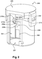
- FIG. 2 shows the valve apparatus 200 according to a particular embodiment of the present invention.
- the valve apparatus 200 comprises a casing 201 defining a main chamber 202.
- the main chamber 202 comprises an inlet orifice 203 (shown in figure 1 ) and an outlet orifice 204 (shown in figure 1 ).
- the valve apparatus 200 comprises a cover 205, which may either be moulded as one part with the casing 201 or it may form a separate part joined to the latter by any known means (mechanical fastening with a seal; welding etc.).
- the cover 205 is a separate part and is clipped on the top of the casing 201.
- the cover 205 comprises a coupling section 206 (shown in figure 1 ) (e.g., a quick-connect coupling or a fir-tree nipple) configured to facilitate coupling to one end of a tube or a pipe and of which other end is connected to a carbon canister 300 (see figure 1 ).
- the valve apparatus 200 comprises a collection and discharge chamber 207 for the liquid droplets, which have been entrained with the gases coming from the tank 100 (shown in figure 1 ).
- the collection and discharge chamber 207 is positioned at the bottom of the main chamber 202. Thus, the droplets can be collected and returned back to the tank, for example by gravity.
- the valve apparatus comprises a float 208 comprising a closure element (non represented), the float 208 being movable inside the main chamber 202 between a first position and a second position in which the communication between the main chamber 202 and the outlet orifice 204(shown in figure 1 ) is closed off by the closure element (non represented).
- the closure element can be a needle seal or a ribbon seal.
- the valve apparatus 200 comprises a weight control system configured for controlling the weight of the float such that the weight of the float in the second position is lower than the weight of the float in the first position. In the illustrated embodiment, the weight transfer of the valve apparatus is insured by a first channel 209 formed in the float 208 and a second channel 210 formed in the casing 201.
- Each channel comprises an inlet orifice 209a, 210a and an outlet orifice 209b, 210b.
- the load which insures the weight control can be in a solid form, liquid or gas form, as long as it can be transferred in and out from the float.
- the weight control system illustrated in these figures comprises one first channel 209 formed in the float 208 and one second channel 210 formed in the casing 201.
- Each channel 209, 210 comprise an inlet orifice 209a, 210a and an outlet orifice 209b, 210b.
- the load which insures the weight control is a ball 211.
- the ball is adapted to roll inside the first and second channels.
- Figure 3A shows the float in a first position.
- the valve apparatus is in an open state (i.e. casing outlet orifice not closed) when the float is in the first position.
- the ball 211 is inside the inlet orifice of the first channel 209 of the float, and the first channel of the float is in communication with the second channel 210 formed in the casing 201 via the inlet orifice of the float and the outlet orifice of the casing.
- Figure 3B shows the float 208 in an intermediate position.
- the valve apparatus 200 is in an intermediate state when the float is in the intermediate position.
- the liquid level increases in the valve apparatus.
- the liquid applies a strong upward push against the float. In other words, the liquid applies force acting on the float.
- the float is moving along from the first position to the second position.
- the ball 211 is in the outlet orifice 209b of the first channel of the float 208, and the first channel 209 of the float 208 is not in communication with the second channel 210 of the casing 201.
- Figure 3C shows the float 208 in a second position.
- the valve apparatus 200 is in a closed state (i.e. float outlet orifice closed) when the float is in the second position.
- the first channel 209 formed in the float is in communication with the second channel 210 formed in the casing via the outlet orifice 209b of the float and the inlet orifice 210a of the casing.
- the communication path created between the first and the second channels 209, 210 allows the transfer of the ball 211 from the float 208 to the casing 201.
- the valve apparatus returns first to the intermediate state.
- the float 208 is moving along from the second position to the first position.
- the ball 211 is in the outlet orifice of the second channel 210b of the casing and the second channel 210 of the casing is not in communication with the first channel 209 of the float.
- the float moves along from the intermediate position to the first position.
- the ball 211 is in the outlet orifice 209b of the first channel of the float and the first channel 209 of the float is in communication with the second channel 210 of the casing.
- the float can eventually move further downwards from the first position.
- the weight control system illustrated in these figures comprises one first channel 209 formed in the float 208 and one second channel 210 formed in the casing 201.
- Each channel 209, 210 comprise an inlet orifice 209a, 210a and an outlet orifice 209b, 210b.
- the load which insures the weight control is a ball 211.
- the ball is adapted to roll inside the first and second channels.
- the channels 209 and 210 have a shape of helicoids, with the outlet 209b and the inlet 210a being located at the same azimuth around the float 208 so that they coincide when the float is in the second position, and the inlet 209a and the outlet 210b being also at another azimuth around the float, but identical for both 209a and 210b so that they coincide when the float is in the first position.
- Figure 4A shows the float in a first position.
- the valve apparatus is in an open state (i.e. casing outlet orifice not closed) when the float is in the first position.
- the ball 211 is inside the inlet orifice of the first channel 209 of the float, and the first channel of the float is in communication with the second channel 210 formed in the casing 201 via the inlet orifice of the float and the outlet orifice of the casing.
- Figure 4B shows the float 208 in an intermediate position.
- the valve apparatus 200 is in an intermediate state when the float is in the intermediate position.
- the liquid level increases in the valve apparatus.
- the liquid applies a strong upward push against the float. In other words, the liquid applies force acting on the float.
- the float is moving along from the first position to the second position.
- the ball 211 is in the outlet orifice 209b of the first channel of the float 208, and the first channel 209 of the float 208 is not in communication with the second channel 210 of the casing 201.
- Figure 4C shows the float 208 in a second position.
- the valve apparatus 200 is in a closed state (i.e. float outlet orifice closed) when the float is in the second position.
- the first channel 209 formed in the float is in communication with the second channel 210 formed in the casing via the outlet orifice 209b of the float and the inlet orifice 210a of the casing.
- the communication path created between the first and the second channels 209, 210 allows the transfer of the ball 211 from the float 208 to the casing 201.
- the valve apparatus returns first to the intermediate state.
- the float 208 is moving along from the second position to the first position.
- the ball 211 is in the outlet orifice of the second channel 210b of the casing and the second channel 210 of the casing is not in communication with the first channel 209 of the float.
- the float moves along from the intermediate position to the first position.
- the ball 211 is in the outlet orifice 209b of the first channel of the float and the first channel 209 of the float is in communication with the second channel 210 of the casing.
- the float can eventually move further downwards from the first position.
- valve apparatus according to the present invention and described above in relation to figures 1-4 , can be separately manufactured by injection molding process and then assembled together.
- the entire or major part of the constituent elements of the valve apparatus according to the present invention can be manufactured by additive manufacturing process.
- Said additive manufacturing process can be laser additive manufacturing, laser engineered net shaping, selective laser sintering, electron-beam projection lithography, fused deposition modeling or electron beam melting. Such processes are known in the art.
- valve apparatus of the present invention can also be used in a vehicle tank for the storage of ammonia precursor solutions or ammonia solutions,the latter being especially interesting because of their high vapor pressure, or for the storage of fuel-borne catalysts or exhaust after-treatment additives (for instance, products sold under the tradename Eolys).
Abstract
- a casing defining a main chamber, the main chamber having at least one inlet orifice and at least one outlet orifice;
- a float comprising a closure element, the float being movable inside the main chamber between a first position and a second position in which said at least one outlet orifice is closed off by the closure element;
- a weight control system configured for controlling the weight of the float by transferring a load in and out from the float, such that the weight of the float in the second position is lower than the weight of the float in the first position.
Description
- The present invention relates to a valve apparatus for the venting of a liquid tank, in particular a fuel tank with which a motor vehicle may be equipped.
- Fuel tanks for motor vehicles are nowadays generally provided with a venting circuit. This circuit allows air to be introduced into the tank in the event of under pressure (especially for compensating for the volume of liquid consumed) or allows the gases contained in the tank to be removed in the event of overpressure. This circuit also allows the ducting and possible filtering of the gases that have to be discharged into the atmosphere, for the purpose of meeting the ever stricter environmental requirements in this regard. This circuit generally includes a valve which as far as possible prevents liquid from coming out of the tank in the event of said tank rolling over or being at an excessively high angle of inclination. This valve generally comprises a float with a closure element adapted to close off a venting orifice. Constant efforts are being made to provide leak-tight closure of the venting orifice, especially when the valve remains immersed in the liquid for a prolonged period.
- The object of embodiments of the invention is to provide a valve apparatus which operates with greater tight-sealing force. In particular, it is an object of the invention to provide a valve apparatus which reduces or suppresses the risk of leakage of liquid (i.e. static leakage) without modifying the Shut Off Height (SOH) of the valve.
- According to an aspect of the invention, there is provided a valve apparatus for use in a liquid tank, said valve apparatus comprising:
- a casing defining a main chamber, the main chamber having at least one inlet orifice and at least one outlet orifice;
- a float comprising a closure element, the float being movable inside the main chamber between a first position and a second position in which said at least one outlet orifice is closed off by the closure element;
- a weight control system configured for controlling the weight of the float by transferring a load in and out from the float, such that the weight of the float in the second position is lower than the weight of the float in the first position.
- Thus, it is proposed a valve apparatus equipped with a variable-weight float. More precisely, the weight control system according to the invention allows the float to have a first weight in the first position and a second weight in the second position, and the second weight is less than the first weight.
In a particular embodiment, the second position can be a position in which the float positions the closure element such that it closes (partially or totally) the outlet orifice(s) and the first position can be a position in which the closure element does not close (partially or totally) the outlet orifice(s).
In a particular embodiment, the first position can be the position in which the float is at rest within the main chamber. In the rest position the float may seat on a support provided in the main chamber.
Embodiments of the invention are based inter alia on the inventive insight that the weight of the float can be reduced (when the float occupies the second position) to increase the tight-sealing force (i.e. closing force on the outlet orifice(s)).
More in particular, the inventors have realized that it is possible to lighten the float in a manner such that the buoyant upward force acting on the float can have a greater effect.
In a particular embodiment, the float can be lightened (i.e. unballasted) in a progressive manner, in the sense that the weight control system according to the invention can lighten continuously or gradually the float as it moves along from the first position to the second position.
In another particular embodiment, the float can be lightened (i.e. unballasted) once it reaches the second position.
In yet another particular embodiment, the float can be lightened at a predetermined position before the closure element reaches or contacts with the outlet orifice(s). - The valve apparatus according to the invention is intended for the venting of a tank, which may contain any liquid.
- In particular, the liquid may be a fuel. The tank may be intended for any use, especially for equipping a vehicle and more especially for equipping a motor vehicle.
- In a particular embodiment, the size and shape of the casing of the valve apparatus according to the invention can be chosen in such a way that the valve apparatus can be entirely disposed in the interior of the tank, preferably by attachment to the inside of the top wall of the tank.
- In a particular embodiment, the casing of the valve apparatus comprises a top surface comprising a bonding feature for facilitating the welding of the casing to the interior of the tank.
- In another particular embodiment, the casing of the valve apparatus comprises bonding features for facilitating the welding of the casing to the external surface of the top wall of the tank.
- In another particular embodiment, the casing of the valve apparatus is a part or is fixed to a flange or a support adapted to be attached to the tank. The main chamber can have one outlet orifice. Alternatively, the main chamber can have several outlet orifices. With this latter particular configuration, the reopening pressure can be reduced.
- The valve apparatus according to the invention allows a liquid tank to be vented, both in normal operation and when filling. Further, it has the function of preventing ingress of liquid in the event of a vehicle rolling over or being excessively tilted.
- Advantageously, the constituent elements of the valve apparatus may be made of any material. Preferably, they are based on a thermoplastic. In this case, it is obviously convenient to choose the material or materials in such a way that they withstand the operating stresses. Of course, the materials chosen must be compatible with the liquids with which they have to be in contact, in particular compatible with the fuels.
In particular in the case in which the liquid tank is a fuel tank made of plastic, most of the constituent elements of the valve apparatus according to the invention are also made of plastic. The term "plastic" is understood to mean any polymeric synthetic material, whether thermoplastic or thermosetting, as well as blends of at least two of these materials. The intended polymers comprise both homopolymers and copolymers (especially binary or ternary copolymers). Examples of such copolymers are, non-limitingly: random copolymers, linear block copolymers, non-linear block copolymers, and graft copolymers. Thermoplastic polymers, including thermoplastic elastomers, and blends thereof are preferred. Any type of thermoplastic polymer or copolymer is suitable. - In a particular embodiment, the closure element is made of rubber. In a particular embodiment, the closure element can be a needle seal or a ribbon seal.
- In a particular embodiment, the weight control system is configured for adding weight to the float in the first position and for relieving weight on the float in the second position.
Thus, the weight control system can increase the weight of the float in the first position and can reduce the weight of the float in the second position, such that the weight of the float in the second position is lower than the weight of the float in the first position. Therefore, the weight control system allows a precise control of the weight ratio between the first position and the second position. This allows an optimized control of the tight-sealing force. - In a particular embodiment, the load can be in a solid form, liquid or gas form. In the particular embodiment where the load is in a solid form, the load can be of any shape, as long as it can be transferred in and out from the float.
In the particular embodiment where the load is in a liquid or gas form, the load can be transferred in or out from the float by the communicating vessels principle.
The float according to the invention can accommodate a load. For example, the float can comprise internal housing(s) and/or channel(s) for accommodating the load.
In a particular embodiment, the weight control system can be a mechanical based system. In one example, the weight control system can use gravity to realize the load transfer operations. In another example, the weight control system can comprise a spring-based system to realize the load transfer operations. In another example, the weight control system can comprise a magnet-based system to realize the load transfer operations. In yet another example, the weight control system can be a combination of the above.
In another particular embodiment, the weight control system can be an electronic based system. For example, an electronic control unit can be used to activate the weight control system for injecting a fluid inside the float in the first position and for sucking the fluid out of the float in the second position. - In an advantageous embodiment, the load comprises at least one ball.
The ball(s) may be made of any material. Preferably, the ball is based on a metal or metal alloy.
In a particular embodiment, the weight of the float in the first position is the combination of the self-weight of the float and the weight of the ball(s). The weight of the float in the second position is the self-weight of the float. Thus, the float is lighter in the second position.
In a particular embodiment, the weight control system comprises at least one first channel formed in the float and at least one second channel formed in the casing, said at least one ball being adapted to roll inside the first and second channels, the first and second channels being arranged such that: - in the first position, the first and second channels are in communication with one another so as to allow for transfer of said at least one ball from the casing to the float; and
- in the second position, the first and second channels are in communication with one another so as to allow for transfer of said at least one ball from the float to the casing.
- Advantageously, the first channel(s) is(are) made integral with the float and the second channel(s) is(are) made integral with the casing.
The float can comprise a plurality of first channels and the casing can comprise a plurality of corresponding second channels. In a particular embodiment, the float and the casing can be manufactured by injection molding process or by additive manufacturing process (i.e. 3D printing). - In a particular embodiment, the valve apparatus comprises a plurality of pairs of first channels, a plurality of pairs of second channels and a plurality of balls. The pairs are distributed in a homogeneous manner around the float and the casing. For example and in a non-restrictive way, the valve apparatus comprises three pairs of first and second channels which are distributed relative to one another at 120°.
- In a particular embodiment, the valve apparatus further comprises a collection and discharge chamber for the liquid droplets, which is positioned at the bottom of the main chamber. Thus, the droplets that have been entrained with the gases coming from the tank can be collected and returned back to the tank, for example by gravity.
- According to another aspect of the invention, there is provided a valve assembly comprising a common support supporting a valve apparatus as described above. In a particular embodiment, the common support is further adapted to support other components: another type of valve, a sensor, a fluid conduct, electrical wires.
- According to another aspect of the invention, there is provided a fuel tank comprising at least one valve apparatus or valve assembly as described above, said at least one valve apparatus or valve assembly being attached to said fuel tank.
- According to another aspect of the invention, there is provided a motor vehicle comprising a fuel tank as described above.
- The accompanying drawings are used to illustrate presently preferred non-limiting exemplary embodiments of devices of the present invention. The above and other advantages of the features and objects of the invention will become more apparent and the invention will be better understood from the following detailed description when read in conjunction with the accompanying drawings, in which:
-
Figure 1 illustrates schematically a valve apparatus according to an embodiment of the invention, installed in an exemplary manner in a fuel tank; -
Figure 2 illustrates schematically a cross-section view of the valve apparatus offigure 1 ; -
Figures 3A-3C are schematic views illustrating a sequence of weight transfer according to an embodiment of the present invention, wherein the float is located in a first, an intermediate, and a second position, respectively; and -
Figures 4A-4C are schematic views illustrating the surface of the casing and the float. They show a sequence of weight transfer according to an embodiment of the present invention, wherein the float is located in a first, an intermediate, and a second position, respectively. - Throughout the figures, like reference numerals have been used to designate like features.
- The present invention provides a valve apparatus for the venting of a liquid tank. In a particular embodiment, the valve apparatus of the present invention can be used in a fuel tank of a motor vehicle. The valve apparatus of the present invention can work as a Roll-Over Valve (ROV) or a Fill Limit Vent Valve (FLVV).
- "Fuel" is understood to designate a mix of liquid or liquefied hydrocarbons, as normally used to power internal combustion engines, including fuels known as gasoline, diesel, ethanol, etc. The valve apparatus of the present invention is particularly suited for venting fuel tanks containing fuel having a relatively high vapour pressure such as gasoline.
- The fuel tank used in conjunction with the invention is preferably made of plastic.
The wall of the fuel tank may be composed of a single thermoplastic layer, or of two layers. One or more other possible additional layers may, advantageously, be composed of layers made of a material that is a barrier to liquids and/or gases. Preferably, the nature and thickness of the barrier layer are chosen so as to minimize the permeability of liquids and gases in contact with the internal surface of the tank. Preferably, this layer is based on a barrier resin, that is to say a resin that is impermeable to the fuel such as, for example, EVOH (a partially hydrolysed ethylene/vinyl acetate copolymer). Alternatively, the tank may be subjected to a surface treatment (fluorination or sulphonation) for the purpose of making it impermeable to the fuel. - When the valve apparatus according to the present invention is attached to a fuel tank, it is preferably attached thereto by welding. The welding can be performed during the parison moulding stage of the fuel tank. Alternatively, the welding can be performed after or during the fuel tank finishing operations (boring and welding).
In a particular embodiment, the valve apparatus is attached on the outer surface of the tank, for instance by boring and welding. - Alternatively, the valve apparatus can be attached onto the inner side of an injected shell of a fuel tank or a urea tank by hot plate welding or laser welding or ultrasonic welding.
- In a particular embodiment, a part of the valve apparatus, such that for example and in a non-restrictive way, the cover and/or the casing, can be injected with the tank.
- Alternatively, the valve apparatus can also be attached onto the inner side of a tank shell by an infra-red welding process. Such process is for example described in patent document
US 7,829,819 . - Alternatively, the valve apparatus can be attached to the tank by plastic overmoulding process.
- Alternatively, the valve apparatus can be attached to the tank by a locking ring system or by any other mean known in the state of the art.
-
Figure 1 depicts a sectional schematic view of afuel tank 100 having atank shell 101. Atank filler pipe 104 provides an entry for fuel into thefuel tank 100. Thefuel tank 100 normally has a certain volume ofliquid fuel 102 andvapor space 103. Avalve apparatus 200 according to the present invention is disposed within thefuel tank 100. Thevalve apparatus 200 can be welded on the outer face or the inner face (i.e. internal wall) of thetank shell 101. Thevalve apparatus 200 can also be attached by using rivet-snapping or dovetail technique. Such techniques are well known for a skilled person and should therefore not be explained further. -
Figure 2 shows thevalve apparatus 200 according to a particular embodiment of the present invention.
Thevalve apparatus 200 comprises acasing 201 defining amain chamber 202. Themain chamber 202 comprises an inlet orifice 203 (shown infigure 1 ) and an outlet orifice 204 (shown infigure 1 ). Thevalve apparatus 200 comprises acover 205, which may either be moulded as one part with thecasing 201 or it may form a separate part joined to the latter by any known means (mechanical fastening with a seal; welding etc.). In the illustrated embodiment, thecover 205 is a separate part and is clipped on the top of thecasing 201. Thecover 205 comprises a coupling section 206 (shown infigure 1 ) (e.g., a quick-connect coupling or a fir-tree nipple) configured to facilitate coupling to one end of a tube or a pipe and of which other end is connected to a carbon canister 300 (seefigure 1 ).
Thevalve apparatus 200 comprises a collection anddischarge chamber 207 for the liquid droplets, which have been entrained with the gases coming from the tank 100 (shown infigure 1 ). The collection anddischarge chamber 207 is positioned at the bottom of themain chamber 202. Thus, the droplets can be collected and returned back to the tank, for example by gravity.
The valve apparatus comprises afloat 208 comprising a closure element (non represented), thefloat 208 being movable inside themain chamber 202 between a first position and a second position in which the communication between themain chamber 202 and the outlet orifice 204(shown infigure 1 ) is closed off by the closure element (non represented). The closure element can be a needle seal or a ribbon seal. Thevalve apparatus 200 comprises a weight control system configured for controlling the weight of the float such that the weight of the float in the second position is lower than the weight of the float in the first position.
In the illustrated embodiment, the weight transfer of the valve apparatus is insured by afirst channel 209 formed in thefloat 208 and asecond channel 210 formed in thecasing 201. Each channel comprises aninlet orifice outlet orifice - In the following, it is described with reference to
Figures 3A-3C a sequence of weight transfer according to a particular embodiment of the present invention.
The weight control system illustrated in these figures comprises onefirst channel 209 formed in thefloat 208 and onesecond channel 210 formed in thecasing 201. Eachchannel inlet orifice outlet orifice ball 211. The ball is adapted to roll inside the first and second channels. -
Figure 3A shows the float in a first position. In this particular embodiment, the valve apparatus is in an open state (i.e. casing outlet orifice not closed) when the float is in the first position. Theball 211 is inside the inlet orifice of thefirst channel 209 of the float, and the first channel of the float is in communication with thesecond channel 210 formed in thecasing 201 via the inlet orifice of the float and the outlet orifice of the casing. -
Figure 3B shows thefloat 208 in an intermediate position. In this particular embodiment, thevalve apparatus 200 is in an intermediate state when the float is in the intermediate position. The liquid level increases in the valve apparatus. The liquid applies a strong upward push against the float. In other words, the liquid applies force acting on the float. Thus, the float is moving along from the first position to the second position. - The
ball 211 is in theoutlet orifice 209b of the first channel of thefloat 208, and thefirst channel 209 of thefloat 208 is not in communication with thesecond channel 210 of thecasing 201. -
Figure 3C shows thefloat 208 in a second position. In this particular embodiment, thevalve apparatus 200 is in a closed state (i.e. float outlet orifice closed) when the float is in the second position. Thus, thefirst channel 209 formed in the float is in communication with thesecond channel 210 formed in the casing via theoutlet orifice 209b of the float and theinlet orifice 210a of the casing. The communication path created between the first and thesecond channels ball 211 from thefloat 208 to thecasing 201.
When the liquid level decreases in thevalve apparatus 200, the valve apparatus returns first to the intermediate state. Thefloat 208 is moving along from the second position to the first position. Theball 211 is in the outlet orifice of thesecond channel 210b of the casing and thesecond channel 210 of the casing is not in communication with thefirst channel 209 of the float. - When the liquid level continues to decrease in the
valve apparatus 200 until the valve apparatus returns to the fully open state, the float moves along from the intermediate position to the first position. Theball 211 is in theoutlet orifice 209b of the first channel of the float and thefirst channel 209 of the float is in communication with thesecond channel 210 of the casing. - One will understand that the float can eventually move further downwards from the first position.
- In the following, it is described with reference to
Figures 4A-4C a sequence of weight transfer according to a particular embodiment of the present invention.
The weight control system illustrated in these figures comprises onefirst channel 209 formed in thefloat 208 and onesecond channel 210 formed in thecasing 201. Eachchannel inlet orifice outlet orifice ball 211. The ball is adapted to roll inside the first and second channels. Thechannels outlet 209b and theinlet 210a being located at the same azimuth around thefloat 208 so that they coincide when the float is in the second position, and theinlet 209a and theoutlet 210b being also at another azimuth around the float, but identical for both 209a and 210b so that they coincide when the float is in the first position. -
Figure 4A shows the float in a first position. In this particular embodiment, the valve apparatus is in an open state (i.e. casing outlet orifice not closed) when the float is in the first position. Theball 211 is inside the inlet orifice of thefirst channel 209 of the float, and the first channel of the float is in communication with thesecond channel 210 formed in thecasing 201 via the inlet orifice of the float and the outlet orifice of the casing. -
Figure 4B shows thefloat 208 in an intermediate position. In this particular embodiment, thevalve apparatus 200 is in an intermediate state when the float is in the intermediate position. The liquid level increases in the valve apparatus. - The liquid applies a strong upward push against the float. In other words, the liquid applies force acting on the float. Thus, the float is moving along from the first position to the second position.
Theball 211 is in theoutlet orifice 209b of the first channel of thefloat 208, and thefirst channel 209 of thefloat 208 is not in communication with thesecond channel 210 of thecasing 201. -
Figure 4C shows thefloat 208 in a second position. In this particular embodiment, thevalve apparatus 200 is in a closed state (i.e. float outlet orifice closed) when the float is in the second position. Thus, thefirst channel 209 formed in the float is in communication with thesecond channel 210 formed in the casing via theoutlet orifice 209b of the float and theinlet orifice 210a of the casing. The communication path created between the first and thesecond channels ball 211 from thefloat 208 to thecasing 201.
When the liquid level decreases in thevalve apparatus 200, the valve apparatus returns first to the intermediate state. Thefloat 208 is moving along from the second position to the first position. Theball 211 is in the outlet orifice of thesecond channel 210b of the casing and thesecond channel 210 of the casing is not in communication with thefirst channel 209 of the float. - When the liquid level continues to decrease in the
valve apparatus 200 until the valve apparatus returns to the fully open state, the float moves along from the intermediate position to the first position. Theball 211 is in theoutlet orifice 209b of the first channel of the float and thefirst channel 209 of the float is in communication with thesecond channel 210 of the casing. - One will understand that the float can eventually move further downwards from the first position.
- It is to note that the constituent elements of the valve apparatus according to the present invention and described above in relation to
figures 1-4 , can be separately manufactured by injection molding process and then assembled together. - In an alternative, the entire or major part of the constituent elements of the valve apparatus according to the present invention can be manufactured by additive manufacturing process. Said additive manufacturing process can be laser additive manufacturing, laser engineered net shaping, selective laser sintering, electron-beam projection lithography, fused deposition modeling or electron beam melting. Such processes are known in the art.
- Although the invention has been described hereinabove by reference to specific embodiments, this is done for illustrative and not for limiting purposes.
- It is to note that the valve apparatus of the present invention can also be used in a vehicle tank for the storage of ammonia precursor solutions or ammonia solutions,the latter being especially interesting because of their high vapor pressure, or for the storage of fuel-borne catalysts or exhaust after-treatment additives (for instance, products sold under the tradename Eolys).
- The skilled person will appreciate that other variants of the present invention may be within the scope of the attached claims.
Claims (12)
- A valve apparatus for use in a liquid tank, said valve apparatus comprising:- a casing defining a main chamber, the main chamber having at least one inlet orifice and at least one outlet orifice;- a float comprising a closure element, the float being movable inside the main chamber between a first position and a second position in which said at least one outlet orifice is closed off by the closure element;- a weight control system configured for controlling the weight of the float by transferring a load in and out from the float, such that the weight of the float in the second position is lower than the weight of the float in the first position.
- The valve apparatus according to claim 1, wherein the valve apparatus is in a closed state, when the float is in the second position.
- The valve apparatus according to the preceding claims, wherein the weight control system is configured for adding weight to the float in the first position and for relieving weight on the float in the second position.
- The valve apparatus according to the preceding claims, wherein the weight control system uses gravity to realize the transferring of the load.
- The valve apparatus according to the preceding claims, wherein the load comprises at least one ball.
- The valve apparatus according to claim 5, wherein the weight control system comprises at least one first channel formed in the float and at least one second channel formed in the casing, said at least one ball being adapted to roll inside the first and second channels, the first and second channels being arranged such that:- in the first position, the first and second channels are in communication with one another so as to allow for transfer of said at least one ball from the casing to the float; and- in the second position, the first and second channels are in communication with one another so as to allow for transfer of said at least one ball from the float to the casing.
- The valve apparatus according to claim 6, wherein the first and second channels have a shape of helicoids.
- The valve apparatus according to the preceding claims, wherein it comprises a collection and discharge chamber, which is positioned at the bottom of the main chamber.
- The valve apparatus according to the preceding claims, wherein the casing and the float are made of plastic.
- A valve assembly comprising a common support supporting a valve apparatus according to any of claims 1-9.
- A fuel tank comprising at least one valve apparatus according to any of claims 1-9, said at least one valve apparatus being attached to said fuel tank.
- A motor vehicle comprising a fuel tank according to claim 11.
Applications Claiming Priority (1)
| Application Number | Priority Date | Filing Date | Title |
|---|---|---|---|
| EP15202165.5A EP3184341A1 (en) | 2015-12-22 | 2015-12-22 | Valve apparatus with a weight control system |
Publications (2)
| Publication Number | Publication Date |
|---|---|
| EP3184342A1 true EP3184342A1 (en) | 2017-06-28 |
| EP3184342B1 EP3184342B1 (en) | 2021-04-14 |
Family
ID=55024908
Family Applications (2)
| Application Number | Title | Priority Date | Filing Date |
|---|---|---|---|
| EP15202165.5A Withdrawn EP3184341A1 (en) | 2015-12-22 | 2015-12-22 | Valve apparatus with a weight control system |
| EP16203471.4A Active EP3184342B1 (en) | 2015-12-22 | 2016-12-12 | Valve apparatus with a weight control system |
Family Applications Before (1)
| Application Number | Title | Priority Date | Filing Date |
|---|---|---|---|
| EP15202165.5A Withdrawn EP3184341A1 (en) | 2015-12-22 | 2015-12-22 | Valve apparatus with a weight control system |
Country Status (3)
| Country | Link |
|---|---|
| US (1) | US10183575B2 (en) |
| EP (2) | EP3184341A1 (en) |
| CN (1) | CN106907519B (en) |
Citations (6)
| Publication number | Priority date | Publication date | Assignee | Title |
|---|---|---|---|---|
| US4274431A (en) * | 1979-01-10 | 1981-06-23 | Keller Russell D | Fuel vent with gravity valve |
| US4735226A (en) * | 1986-03-07 | 1988-04-05 | Stant Inc. | Anti-lift roll-over valve |
| US6450192B1 (en) * | 1998-05-28 | 2002-09-17 | Compagnie De Materiel Et D'equipements Techniques C.O.M.E.T. | Device for ventilating a motor vehicle fuel tank |
| US20040007262A1 (en) * | 2002-07-10 | 2004-01-15 | Nifco Inc. | Pressure control valve for fuel tank |
| US7829819B2 (en) | 2007-02-08 | 2010-11-09 | Automotive Components Holdings, Llc | Attaching a component to an internal surface of a tank formed of polymer |
| US20110162728A1 (en) * | 2009-04-22 | 2011-07-07 | Eaton Corporation | Valve assembly for high-pressure fluid reservoir |
Family Cites Families (4)
| Publication number | Priority date | Publication date | Assignee | Title |
|---|---|---|---|---|
| US1906052A (en) * | 1928-07-05 | 1933-04-25 | Milwaukee Valve Co | Boiler return trap |
| US7314104B2 (en) * | 2004-12-24 | 2008-01-01 | Ketcham John C | Steam driven road vehicle |
| US8171952B2 (en) * | 2008-02-01 | 2012-05-08 | Eaton Corporation | Multi-function control valve for fuel vapor system |
| EP2647516B1 (en) * | 2012-04-03 | 2014-12-17 | Inergy Automotive Systems Research (Société Anonyme) | Method and valve for the venting of a saddle fuel tank |
-
2015
- 2015-12-22 EP EP15202165.5A patent/EP3184341A1/en not_active Withdrawn
-
2016
- 2016-12-12 EP EP16203471.4A patent/EP3184342B1/en active Active
- 2016-12-19 US US15/383,149 patent/US10183575B2/en not_active Expired - Fee Related
- 2016-12-21 CN CN201611190642.8A patent/CN106907519B/en active Active
Patent Citations (6)
| Publication number | Priority date | Publication date | Assignee | Title |
|---|---|---|---|---|
| US4274431A (en) * | 1979-01-10 | 1981-06-23 | Keller Russell D | Fuel vent with gravity valve |
| US4735226A (en) * | 1986-03-07 | 1988-04-05 | Stant Inc. | Anti-lift roll-over valve |
| US6450192B1 (en) * | 1998-05-28 | 2002-09-17 | Compagnie De Materiel Et D'equipements Techniques C.O.M.E.T. | Device for ventilating a motor vehicle fuel tank |
| US20040007262A1 (en) * | 2002-07-10 | 2004-01-15 | Nifco Inc. | Pressure control valve for fuel tank |
| US7829819B2 (en) | 2007-02-08 | 2010-11-09 | Automotive Components Holdings, Llc | Attaching a component to an internal surface of a tank formed of polymer |
| US20110162728A1 (en) * | 2009-04-22 | 2011-07-07 | Eaton Corporation | Valve assembly for high-pressure fluid reservoir |
Also Published As
| Publication number | Publication date |
|---|---|
| US10183575B2 (en) | 2019-01-22 |
| CN106907519B (en) | 2020-08-28 |
| EP3184342B1 (en) | 2021-04-14 |
| US20170174073A1 (en) | 2017-06-22 |
| CN106907519A (en) | 2017-06-30 |
| EP3184341A1 (en) | 2017-06-28 |
Similar Documents
| Publication | Publication Date | Title |
|---|---|---|
| US7913671B2 (en) | Device for the venting circuit of a liquid tank and valve incorporating said device | |
| JP4975740B2 (en) | Valve used in liquid tank exhaust circuit | |
| US10632837B2 (en) | Valve apparatus for venting a liquid tank | |
| KR101412359B1 (en) | Liquid tank and method for manufacturing it | |
| EP2588339B1 (en) | Plastic fuel tank with increased deformation stability | |
| KR101472724B1 (en) | Valve for the venting circuit of a liquid tank | |
| KR20190003812A (en) | Fuel tank with improved mechanical resistance | |
| US20120073548A1 (en) | Fuel Tank Valve Structure Controlling Emission Gas in Hybrid Vehicle | |
| JP2012506337A (en) | Fuel tank with ventilation system equipped with gas-liquid separator | |
| JP5839740B2 (en) | Fuel tank or secondary fluid tank for automobile | |
| EP3184342B1 (en) | Valve apparatus with a weight control system | |
| US9108507B2 (en) | Fuel tank and method of manufacturing the same | |
| KR20090051249A (en) | Valve for the venting circuit of a liquid tank | |
| JP2005199792A (en) | Fuel cut-off valve, and fuel feeding device for fuel tank | |
| JP2019065806A (en) | Fuel shut-off valve | |
| JP2004300939A (en) | Fuel outflow regulating device of fuel tank |
Legal Events
| Date | Code | Title | Description |
|---|---|---|---|
| PUAI | Public reference made under article 153(3) epc to a published international application that has entered the european phase |
Free format text: ORIGINAL CODE: 0009012 |
|
| STAA | Information on the status of an ep patent application or granted ep patent |
Free format text: STATUS: THE APPLICATION HAS BEEN PUBLISHED |
|
| AK | Designated contracting states |
Kind code of ref document: A1 Designated state(s): AL AT BE BG CH CY CZ DE DK EE ES FI FR GB GR HR HU IE IS IT LI LT LU LV MC MK MT NL NO PL PT RO RS SE SI SK SM TR |
|
| AX | Request for extension of the european patent |
Extension state: BA ME |
|
| STAA | Information on the status of an ep patent application or granted ep patent |
Free format text: STATUS: REQUEST FOR EXAMINATION WAS MADE |
|
| 17P | Request for examination filed |
Effective date: 20171212 |
|
| RBV | Designated contracting states (corrected) |
Designated state(s): AL AT BE BG CH CY CZ DE DK EE ES FI FR GB GR HR HU IE IS IT LI LT LU LV MC MK MT NL NO PL PT RO RS SE SI SK SM TR |
|
| RAP1 | Party data changed (applicant data changed or rights of an application transferred) |
Owner name: PLASTIC OMNIUM ADVANCED INNOVATION AND RESEARCH |
|
| STAA | Information on the status of an ep patent application or granted ep patent |
Free format text: STATUS: EXAMINATION IS IN PROGRESS |
|
| 17Q | First examination report despatched |
Effective date: 20200703 |
|
| GRAP | Despatch of communication of intention to grant a patent |
Free format text: ORIGINAL CODE: EPIDOSNIGR1 |
|
| STAA | Information on the status of an ep patent application or granted ep patent |
Free format text: STATUS: GRANT OF PATENT IS INTENDED |
|
| INTG | Intention to grant announced |
Effective date: 20201124 |
|
| GRAS | Grant fee paid |
Free format text: ORIGINAL CODE: EPIDOSNIGR3 |
|
| GRAA | (expected) grant |
Free format text: ORIGINAL CODE: 0009210 |
|
| STAA | Information on the status of an ep patent application or granted ep patent |
Free format text: STATUS: THE PATENT HAS BEEN GRANTED |
|
| AK | Designated contracting states |
Kind code of ref document: B1 Designated state(s): AL AT BE BG CH CY CZ DE DK EE ES FI FR GB GR HR HU IE IS IT LI LT LU LV MC MK MT NL NO PL PT RO RS SE SI SK SM TR |
|
| REG | Reference to a national code |
Ref country code: GB Ref legal event code: FG4D |
|
| REG | Reference to a national code |
Ref country code: CH Ref legal event code: EP |
|
| REG | Reference to a national code |
Ref country code: DE Ref legal event code: R096 Ref document number: 602016056006 Country of ref document: DE |
|
| REG | Reference to a national code |
Ref country code: IE Ref legal event code: FG4D |
|
| REG | Reference to a national code |
Ref country code: AT Ref legal event code: REF Ref document number: 1382044 Country of ref document: AT Kind code of ref document: T Effective date: 20210515 |
|
| REG | Reference to a national code |
Ref country code: LT Ref legal event code: MG9D |
|
| REG | Reference to a national code |
Ref country code: AT Ref legal event code: MK05 Ref document number: 1382044 Country of ref document: AT Kind code of ref document: T Effective date: 20210414 |
|
| REG | Reference to a national code |
Ref country code: NL Ref legal event code: MP Effective date: 20210414 |
|
| PG25 | Lapsed in a contracting state [announced via postgrant information from national office to epo] |
Ref country code: HR Free format text: LAPSE BECAUSE OF FAILURE TO SUBMIT A TRANSLATION OF THE DESCRIPTION OR TO PAY THE FEE WITHIN THE PRESCRIBED TIME-LIMIT Effective date: 20210414 Ref country code: AT Free format text: LAPSE BECAUSE OF FAILURE TO SUBMIT A TRANSLATION OF THE DESCRIPTION OR TO PAY THE FEE WITHIN THE PRESCRIBED TIME-LIMIT Effective date: 20210414 Ref country code: BG Free format text: LAPSE BECAUSE OF FAILURE TO SUBMIT A TRANSLATION OF THE DESCRIPTION OR TO PAY THE FEE WITHIN THE PRESCRIBED TIME-LIMIT Effective date: 20210714 Ref country code: LT Free format text: LAPSE BECAUSE OF FAILURE TO SUBMIT A TRANSLATION OF THE DESCRIPTION OR TO PAY THE FEE WITHIN THE PRESCRIBED TIME-LIMIT Effective date: 20210414 Ref country code: NL Free format text: LAPSE BECAUSE OF FAILURE TO SUBMIT A TRANSLATION OF THE DESCRIPTION OR TO PAY THE FEE WITHIN THE PRESCRIBED TIME-LIMIT Effective date: 20210414 Ref country code: FI Free format text: LAPSE BECAUSE OF FAILURE TO SUBMIT A TRANSLATION OF THE DESCRIPTION OR TO PAY THE FEE WITHIN THE PRESCRIBED TIME-LIMIT Effective date: 20210414 |
|
| PG25 | Lapsed in a contracting state [announced via postgrant information from national office to epo] |
Ref country code: IS Free format text: LAPSE BECAUSE OF FAILURE TO SUBMIT A TRANSLATION OF THE DESCRIPTION OR TO PAY THE FEE WITHIN THE PRESCRIBED TIME-LIMIT Effective date: 20210814 Ref country code: LV Free format text: LAPSE BECAUSE OF FAILURE TO SUBMIT A TRANSLATION OF THE DESCRIPTION OR TO PAY THE FEE WITHIN THE PRESCRIBED TIME-LIMIT Effective date: 20210414 Ref country code: GR Free format text: LAPSE BECAUSE OF FAILURE TO SUBMIT A TRANSLATION OF THE DESCRIPTION OR TO PAY THE FEE WITHIN THE PRESCRIBED TIME-LIMIT Effective date: 20210715 Ref country code: PT Free format text: LAPSE BECAUSE OF FAILURE TO SUBMIT A TRANSLATION OF THE DESCRIPTION OR TO PAY THE FEE WITHIN THE PRESCRIBED TIME-LIMIT Effective date: 20210816 Ref country code: PL Free format text: LAPSE BECAUSE OF FAILURE TO SUBMIT A TRANSLATION OF THE DESCRIPTION OR TO PAY THE FEE WITHIN THE PRESCRIBED TIME-LIMIT Effective date: 20210414 Ref country code: NO Free format text: LAPSE BECAUSE OF FAILURE TO SUBMIT A TRANSLATION OF THE DESCRIPTION OR TO PAY THE FEE WITHIN THE PRESCRIBED TIME-LIMIT Effective date: 20210714 Ref country code: RS Free format text: LAPSE BECAUSE OF FAILURE TO SUBMIT A TRANSLATION OF THE DESCRIPTION OR TO PAY THE FEE WITHIN THE PRESCRIBED TIME-LIMIT Effective date: 20210414 Ref country code: SE Free format text: LAPSE BECAUSE OF FAILURE TO SUBMIT A TRANSLATION OF THE DESCRIPTION OR TO PAY THE FEE WITHIN THE PRESCRIBED TIME-LIMIT Effective date: 20210414 |
|
| REG | Reference to a national code |
Ref country code: DE Ref legal event code: R097 Ref document number: 602016056006 Country of ref document: DE |
|
| PG25 | Lapsed in a contracting state [announced via postgrant information from national office to epo] |
Ref country code: RO Free format text: LAPSE BECAUSE OF FAILURE TO SUBMIT A TRANSLATION OF THE DESCRIPTION OR TO PAY THE FEE WITHIN THE PRESCRIBED TIME-LIMIT Effective date: 20210414 Ref country code: ES Free format text: LAPSE BECAUSE OF FAILURE TO SUBMIT A TRANSLATION OF THE DESCRIPTION OR TO PAY THE FEE WITHIN THE PRESCRIBED TIME-LIMIT Effective date: 20210414 Ref country code: SK Free format text: LAPSE BECAUSE OF FAILURE TO SUBMIT A TRANSLATION OF THE DESCRIPTION OR TO PAY THE FEE WITHIN THE PRESCRIBED TIME-LIMIT Effective date: 20210414 Ref country code: SM Free format text: LAPSE BECAUSE OF FAILURE TO SUBMIT A TRANSLATION OF THE DESCRIPTION OR TO PAY THE FEE WITHIN THE PRESCRIBED TIME-LIMIT Effective date: 20210414 Ref country code: DK Free format text: LAPSE BECAUSE OF FAILURE TO SUBMIT A TRANSLATION OF THE DESCRIPTION OR TO PAY THE FEE WITHIN THE PRESCRIBED TIME-LIMIT Effective date: 20210414 Ref country code: CZ Free format text: LAPSE BECAUSE OF FAILURE TO SUBMIT A TRANSLATION OF THE DESCRIPTION OR TO PAY THE FEE WITHIN THE PRESCRIBED TIME-LIMIT Effective date: 20210414 Ref country code: EE Free format text: LAPSE BECAUSE OF FAILURE TO SUBMIT A TRANSLATION OF THE DESCRIPTION OR TO PAY THE FEE WITHIN THE PRESCRIBED TIME-LIMIT Effective date: 20210414 |
|
| PLBE | No opposition filed within time limit |
Free format text: ORIGINAL CODE: 0009261 |
|
| STAA | Information on the status of an ep patent application or granted ep patent |
Free format text: STATUS: NO OPPOSITION FILED WITHIN TIME LIMIT |
|
| 26N | No opposition filed |
Effective date: 20220117 |
|
| PG25 | Lapsed in a contracting state [announced via postgrant information from national office to epo] |
Ref country code: IS Free format text: LAPSE BECAUSE OF FAILURE TO SUBMIT A TRANSLATION OF THE DESCRIPTION OR TO PAY THE FEE WITHIN THE PRESCRIBED TIME-LIMIT Effective date: 20210814 Ref country code: AL Free format text: LAPSE BECAUSE OF FAILURE TO SUBMIT A TRANSLATION OF THE DESCRIPTION OR TO PAY THE FEE WITHIN THE PRESCRIBED TIME-LIMIT Effective date: 20210414 |
|
| REG | Reference to a national code |
Ref country code: DE Ref legal event code: R119 Ref document number: 602016056006 Country of ref document: DE |
|
| PG25 | Lapsed in a contracting state [announced via postgrant information from national office to epo] |
Ref country code: MC Free format text: LAPSE BECAUSE OF FAILURE TO SUBMIT A TRANSLATION OF THE DESCRIPTION OR TO PAY THE FEE WITHIN THE PRESCRIBED TIME-LIMIT Effective date: 20210414 Ref country code: IT Free format text: LAPSE BECAUSE OF FAILURE TO SUBMIT A TRANSLATION OF THE DESCRIPTION OR TO PAY THE FEE WITHIN THE PRESCRIBED TIME-LIMIT Effective date: 20210414 |
|
| REG | Reference to a national code |
Ref country code: CH Ref legal event code: PL |
|
| GBPC | Gb: european patent ceased through non-payment of renewal fee |
Effective date: 20211212 |
|
| REG | Reference to a national code |
Ref country code: BE Ref legal event code: MM Effective date: 20211231 |
|
| PG25 | Lapsed in a contracting state [announced via postgrant information from national office to epo] |
Ref country code: LU Free format text: LAPSE BECAUSE OF NON-PAYMENT OF DUE FEES Effective date: 20211212 Ref country code: IE Free format text: LAPSE BECAUSE OF NON-PAYMENT OF DUE FEES Effective date: 20211212 Ref country code: GB Free format text: LAPSE BECAUSE OF NON-PAYMENT OF DUE FEES Effective date: 20211212 Ref country code: DE Free format text: LAPSE BECAUSE OF NON-PAYMENT OF DUE FEES Effective date: 20220701 |
|
| PG25 | Lapsed in a contracting state [announced via postgrant information from national office to epo] |
Ref country code: FR Free format text: LAPSE BECAUSE OF NON-PAYMENT OF DUE FEES Effective date: 20211231 Ref country code: BE Free format text: LAPSE BECAUSE OF NON-PAYMENT OF DUE FEES Effective date: 20211231 |
|
| PG25 | Lapsed in a contracting state [announced via postgrant information from national office to epo] |
Ref country code: LI Free format text: LAPSE BECAUSE OF NON-PAYMENT OF DUE FEES Effective date: 20211231 Ref country code: CH Free format text: LAPSE BECAUSE OF NON-PAYMENT OF DUE FEES Effective date: 20211231 |
|
| PG25 | Lapsed in a contracting state [announced via postgrant information from national office to epo] |
Ref country code: HU Free format text: LAPSE BECAUSE OF FAILURE TO SUBMIT A TRANSLATION OF THE DESCRIPTION OR TO PAY THE FEE WITHIN THE PRESCRIBED TIME-LIMIT; INVALID AB INITIO Effective date: 20161212 |
|
| PG25 | Lapsed in a contracting state [announced via postgrant information from national office to epo] |
Ref country code: CY Free format text: LAPSE BECAUSE OF FAILURE TO SUBMIT A TRANSLATION OF THE DESCRIPTION OR TO PAY THE FEE WITHIN THE PRESCRIBED TIME-LIMIT Effective date: 20210414 |
|
| PG25 | Lapsed in a contracting state [announced via postgrant information from national office to epo] |
Ref country code: MK Free format text: LAPSE BECAUSE OF FAILURE TO SUBMIT A TRANSLATION OF THE DESCRIPTION OR TO PAY THE FEE WITHIN THE PRESCRIBED TIME-LIMIT Effective date: 20210414 |