EP3184308A1 - Maintenance member - Google Patents
Maintenance member Download PDFInfo
- Publication number
- EP3184308A1 EP3184308A1 EP16201770.1A EP16201770A EP3184308A1 EP 3184308 A1 EP3184308 A1 EP 3184308A1 EP 16201770 A EP16201770 A EP 16201770A EP 3184308 A1 EP3184308 A1 EP 3184308A1
- Authority
- EP
- European Patent Office
- Prior art keywords
- face
- plate
- portions
- protection
- opposite
- Prior art date
- Legal status (The legal status is an assumption and is not a legal conclusion. Google has not performed a legal analysis and makes no representation as to the accuracy of the status listed.)
- Granted
Links
Images














Classifications
-
- B—PERFORMING OPERATIONS; TRANSPORTING
- B41—PRINTING; LINING MACHINES; TYPEWRITERS; STAMPS
- B41J—TYPEWRITERS; SELECTIVE PRINTING MECHANISMS, i.e. MECHANISMS PRINTING OTHERWISE THAN FROM A FORME; CORRECTION OF TYPOGRAPHICAL ERRORS
- B41J2/00—Typewriters or selective printing mechanisms characterised by the printing or marking process for which they are designed
- B41J2/005—Typewriters or selective printing mechanisms characterised by the printing or marking process for which they are designed characterised by bringing liquid or particles selectively into contact with a printing material
- B41J2/01—Ink jet
- B41J2/135—Nozzles
- B41J2/165—Prevention or detection of nozzle clogging, e.g. cleaning, capping or moistening for nozzles
- B41J2/16517—Cleaning of print head nozzles
-
- B—PERFORMING OPERATIONS; TRANSPORTING
- B41—PRINTING; LINING MACHINES; TYPEWRITERS; STAMPS
- B41J—TYPEWRITERS; SELECTIVE PRINTING MECHANISMS, i.e. MECHANISMS PRINTING OTHERWISE THAN FROM A FORME; CORRECTION OF TYPOGRAPHICAL ERRORS
- B41J2/00—Typewriters or selective printing mechanisms characterised by the printing or marking process for which they are designed
- B41J2/005—Typewriters or selective printing mechanisms characterised by the printing or marking process for which they are designed characterised by bringing liquid or particles selectively into contact with a printing material
- B41J2/01—Ink jet
- B41J2/135—Nozzles
- B41J2/165—Prevention or detection of nozzle clogging, e.g. cleaning, capping or moistening for nozzles
- B41J2/16517—Cleaning of print head nozzles
- B41J2/16535—Cleaning of print head nozzles using wiping constructions
- B41J2/16538—Cleaning of print head nozzles using wiping constructions with brushes or wiper blades perpendicular to the nozzle plate
-
- B—PERFORMING OPERATIONS; TRANSPORTING
- B41—PRINTING; LINING MACHINES; TYPEWRITERS; STAMPS
- B41J—TYPEWRITERS; SELECTIVE PRINTING MECHANISMS, i.e. MECHANISMS PRINTING OTHERWISE THAN FROM A FORME; CORRECTION OF TYPOGRAPHICAL ERRORS
- B41J2/00—Typewriters or selective printing mechanisms characterised by the printing or marking process for which they are designed
- B41J2/005—Typewriters or selective printing mechanisms characterised by the printing or marking process for which they are designed characterised by bringing liquid or particles selectively into contact with a printing material
- B41J2/01—Ink jet
- B41J2/135—Nozzles
- B41J2/165—Prevention or detection of nozzle clogging, e.g. cleaning, capping or moistening for nozzles
- B41J2/16517—Cleaning of print head nozzles
- B41J2/16535—Cleaning of print head nozzles using wiping constructions
- B41J2/16541—Means to remove deposits from wipers or scrapers
-
- B—PERFORMING OPERATIONS; TRANSPORTING
- B41—PRINTING; LINING MACHINES; TYPEWRITERS; STAMPS
- B41J—TYPEWRITERS; SELECTIVE PRINTING MECHANISMS, i.e. MECHANISMS PRINTING OTHERWISE THAN FROM A FORME; CORRECTION OF TYPOGRAPHICAL ERRORS
- B41J2/00—Typewriters or selective printing mechanisms characterised by the printing or marking process for which they are designed
- B41J2/005—Typewriters or selective printing mechanisms characterised by the printing or marking process for which they are designed characterised by bringing liquid or particles selectively into contact with a printing material
- B41J2/01—Ink jet
- B41J2/135—Nozzles
- B41J2/165—Prevention or detection of nozzle clogging, e.g. cleaning, capping or moistening for nozzles
- B41J2/16517—Cleaning of print head nozzles
- B41J2/16535—Cleaning of print head nozzles using wiping constructions
- B41J2/16544—Constructions for the positioning of wipers
-
- B—PERFORMING OPERATIONS; TRANSPORTING
- B41—PRINTING; LINING MACHINES; TYPEWRITERS; STAMPS
- B41J—TYPEWRITERS; SELECTIVE PRINTING MECHANISMS, i.e. MECHANISMS PRINTING OTHERWISE THAN FROM A FORME; CORRECTION OF TYPOGRAPHICAL ERRORS
- B41J2/00—Typewriters or selective printing mechanisms characterised by the printing or marking process for which they are designed
- B41J2/005—Typewriters or selective printing mechanisms characterised by the printing or marking process for which they are designed characterised by bringing liquid or particles selectively into contact with a printing material
- B41J2/01—Ink jet
- B41J2/21—Ink jet for multi-colour printing
Definitions
- the present invention relates to a maintenance member that is configured to anchor to a plate an absorption member that absorbs ink.
- An inkjet printer is known that is provided with a wiper and a liquid recovery part.
- the wiper removes a liquid, such as an ink or the like, from a nozzle forming surface on which a nozzle is formed.
- the liquid recovery part recovers the liquid, such as an ink or the like, that has been scraped off by the wiper.
- Japanese Laid-Open Patent Publication No. 2015-33784 discloses an inkjet printer that is provided with a liquid jet part, a wiper and a liquid recovery part.
- the liquid jet part includes a liquid jet head and a carriage.
- the liquid jet head includes a nozzle forming surface in which a nozzle is formed.
- the carriage holds the liquid jet head.
- the wiper comes into contact with the nozzle forming surface and wipes off the ink that has adhered to the nozzle forming surface.
- the liquid recovery part is provided with a scraper part and a liquid absorption material.
- the scraper part comes into contact with the wiper and scrapes off the ink that has adhered to the wiper.
- the liquid absorption material is disposed in a position where it is not in contact with the wiper but is in contact with an edge portion of a scraping surface.
- the scraping surface scrapes off the ink that has adhered to the wiper. In the process, the ink adheres to the scraping surface.
- the liquid absorption material absorbs from the edge portion of the scraping surface the ink that has adhered to the scraping surface.
- the liquid absorption material of the liquid recovery part may be made to absorb a moisturizing liquid or the like in advance, in order to inhibit the ink that the liquid absorption material has absorbed from returning to the wiper.
- the liquid recovery part can be replaced.
- a liquid such as the moisturizing liquid or the like can be inhibited from evaporating from the liquid absorption material of the replacement liquid recovery part by packaging the replacement liquid recovery part in a bag.
- a maintenance member of the present invention includes a plate, an absorption member, a plate edge, opening edge portions, and a protection plate.
- the plate includes a first face and a second face disposed on the opposite side from the first face.
- the absorption member is configured to absorb ink.
- the absorption member includes an opposite face and an exposed face. The opposite face opposes the first face.
- the exposed face is disposed on the opposite side from the opposite face.
- the absorption member is disposed on the first face and has absorbed a liquid.
- the plate edge is located in a thickness direction from the exposed face. The thickness direction is the direction from the first face toward the second face.
- the plate edge is an edge of the plate on the side of the plate in an extension direction of the first face.
- the opening edge portions are located in the plate and are opening toward the absorption member from the second face.
- the protection plate is fixed in place such that a gap is provided between the protection plate and the absorption member.
- the protection plate is configured to protect the absorption member from contact. For example, the protection plate protects the absorption member when the maintenance member is stored. Because a space is provided between the protection plate and the absorption member, it is possible, for example, to prevent an external pressure that presses on the protection plate from pressing on the absorption member. Therefore, the possibility that the liquid will seep out of the absorption member may be decreased.
- the plate may be configured to be mounted in a print device.
- the print device may be configured to recover ink adhering to a wiper.
- the wiper may be configured to wipe off ink adhering to a nozzle formation face of a print head.
- the print head may be configured to discharge ink. Therefore, the absorption member may recover ink that has adhered to the wiper.
- the plate may include a first projection portion projecting farther than the absorption member on the first face. Therefore, the first projection portion may ensure the space between the absorption member and the protection plate.
- the protection plate may include a first opposite projection portion in a position opposite the first projection portion. Therefore, the first opposite projection portion may ensure the space between the absorption member and the protection plate.
- the protection plate may include a pair of the first opposite projection portions, with a space between the pair of the first opposite projection portions.
- the space may be recessed in relation to the pair of the first opposite projection portions. Therefore, the absorption member may be disposed in the recessed space between the pair of the first opposite projection portions.
- the plate may include an engagement portion projecting in an orthogonal direction orthogonal to the extension direction of the first face in the first face.
- the protection plate may include a protection face and a wall.
- the protection face may oppose the absorption member.
- the wall may extend from the protection face in a direction crossing the protection face.
- the wall may include an engaged portion.
- the engaged portion may project in an extension direction of the protection face and be configured to engage with the engagement portion.
- the engaged portion may be configured to engage with the engagement portion by flexing in an extension direction of the wall. Therefore, this structure may protect the absorption member, because the plate does not readily fall off when the maintenance member is dropped, for example.
- the plate may include a first projection portion projecting farther than the absorption member on the first face.
- the protection plate may include a first opposite projection portion in a position opposite the first projection portion.
- the engaged portion may be disposed to the outside from the first opposite projection portion. Therefore, the engaged portion, being set apart by a specified distance, may hold the plate in a stable manner.
- the outside in the orthogonal direction may correspond to one direction or the other direction in the orthogonal direction from the center in the orthogonal direction.
- the inside in the orthogonal direction may correspond to any direction in the orthogonal direction toward the center in the orthogonal direction.
- the first opposite projection portion may also be disposed between the engaged portion and the absorption member in the extension direction of the first face.
- the area to the outside from the first opposite projection portion may be recessed in relation to the first opposite projection portion. Therefore, the recessed area to the outside from the first opposite projection portion may ensure a greater range of flexure for the engaged portion.
- the wall may include a pair of the engaged portions.
- the wall may include at least one rib between the pair of the engaged portions. Therefore, the at least one rib may make it easy for the pair of the engagement portions to engage with and disengage from the pair of the engaged portions.
- the length of the engagement portion in the extension direction of the first face may be greater than the length of the engagement portion in a thickness direction of the engagement portion.
- the thickness direction of the engagement portion may be orthogonal to the extension direction of the first face and to the orthogonal direction. Therefore, the maintenance member may be mounted in and removed from a device by rotating the maintenance member.
- the protection plate may include a bottom plate disposed such that a gap is provided between the protection plate and the bottom plate.
- the plate may include a pair of the first projection portions and a second projection portion.
- the second projection portion may be disposed between the pair of the first projection portions.
- the second projection portion may project in the same direction as the pair of the first projection portions.
- the second projection portion may not come into contact with the protection plate in a state in which the pair of the first opposite projection portions oppose the pair of the first projection portions.
- the second projection portion may come into contact with the bottom plate in a state in which the pair of the first opposite projection portions and the pair of the first projection portions are on opposite sides of the plate. Therefore, the operator may be prevented from mounting the maintenance member by mistake when the plate is not oriented correctly.
- the plate may include a pair of third projection portions projecting from the second face of the plate.
- the bottom plate may be recessed across a wider space than the space between the pair of the third projection portions. Therefore, the pair of the third projection portions may be disposed on the bottom plate, which is recessed across a wide space.
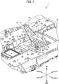
- FIGS. 1 to 8 The configuration of a printer 1 will be explained with reference to FIGS. 1 to 8 .
- the terms left, right, front, rear, up, and down that are used are those indicated by the arrows in the drawings.
- the printer 1 is an inkjet printer that prints by discharging an ink that is an example of a liquid onto a cloth such as a T-shirt or the like (not shown in the drawings) that is a printing medium.
- the printing medium may also be a paper or the like.
- the printer 1 is configured to print a color image on the printing medium by discharging downward five different types of the ink (white, black, yellow, cyan, and magenta), for example.
- the ink that is white will be called the white ink.
- the other four types of the ink, black, yellow, cyan, and magenta will be collectively called the color inks.
- the printer 1 is provided with a housing 2, a platen drive mechanism 6, a pair of guide rails (not shown in the drawings), a platen 5, a tray 4, a frame body 10, a shaft 9, a rail 7, a carriage 20, head units 100, 200, a drive belt 101, and a drive motor 19.
- An operation portion (not shown in the drawings) that performs operations of the printer 1 is disposed on the front side of the right portion of the housing 2.
- the operation portion is provided with a display and operation buttons. An operator operates the operation buttons when inputting commands that are related to various types of operations of the printer 1.
- the frame body 10 has a frame shape that is substantially rectangular in a plan view, and it is installed in the top portion of the housing 2.
- the front side of the frame body 10 supports the shaft 9.
- the rear side of the frame body 10 supports the rail 7.
- the shaft 9 extends in the left-right direction on the inner side of the frame body 10.
- the rail 7 is disposed opposite the guide shaft 9 and extends in the left-right direction.
- the carriage 20 is configured to be conveyed to the left and the right along the shaft 9.
- the head units 100, 200 are carried on the carriage 20.
- the head unit 100 is disposed in front of the head unit 200.
- a head 110 is disposed on the bottom of each one of the head units 100, 200.
- a nozzle face 111 is disposed on the bottom face of the each of the heads 110.
- the nozzle face 111 is flat and parallel to the horizontal plane.
- FIG. 3 shows the head 110 and the nozzle face 111 on the head unit 100.
- a plurality of nozzles are disposed in the nozzle face 111 that are configured to discharge one of the white ink and the color inks downward.
- the drive belt 101 spans the inner side of the frame body 10 in the left-right direction.
- the drive motor 19 is provided in the front right portion of the inner side of the frame body 10.
- the drive motor 19 is coupled to the carriage 20 through the drive belt 101.
- the carriage 20 moves reciprocally in the left-right direction (a main scanning direction) along the guide shaft 9.
- the inks are discharged toward the platen 5, which is disposed such that it faces the head units 100, 200.
- the platen drive mechanism 6 is provided with the pair of the guide rails (not shown in the drawings) and a platen support base (not shown in the drawings).
- the pair of the guide rails extend in the front-rear direction on the inner side of the platen drive mechanism 6.
- the pair of the guide rails support the platen support base such that it can move toward the front and the rear.
- the top portion of the platen support base supports the platen 5.
- the platen 5 supports the printing medium.
- the tray 4 is disposed below the platen 5.
- the tray 4 receives the sleeves and the like of the T-shirt when the operator places the T-shirt on the platen 5.
- the tray 4 thus protects sleeves and the like, such that they do not come into contact with other parts in the interior of the housing 2.
- An auxiliary scanning direction drive portion (not shown in the drawings) drives the platen drive mechanism 6.
- the platen drive mechanism 6 moves the platen support base and the platen 5 toward the front and the rear of the housing 2 along the pair of the guide rails.
- the heads 110 discharge the inks as they move reciprocally in the left-right direction.
- the printer 1 thus performs printing on the printing medium.
- the printing area 130 As shown in FIGS. 1 and 2 , along the path that the heads 110 travel, the area where the heads 110 perform printing will be called the printing area 130.
- the area along the path that the heads 110 travel that is outside the printing area 130 will be called the non-printing area 140.
- the non-printing area 140 is an area in the left portion of the printer 1.
- the printing area 130 is the area from the right edge of the non-printing area 140 to the right end of the printer 1.
- the platen 5, the tray 4, and the like are disposed in the printing area 130.
- the maintenance operations include a flushing operation, an ink purge operation, a nozzle face wiping operation, a wiper wiping operation, and the like.
- the flushing operation is an operation that, before printing is performed on the printing medium, discharges the inks from the heads 110 onto a flushing receiving portion 145 (refer to FIG. 2 ) that will be described later.
- the flushing operation makes it possible for the inks to be discharged appropriately from the heads 110, even right after the printing starts.
- the ink purge operation is an operation in which the nozzle faces 111 are capped by nozzle caps 144 (refer to FIG.
- the ink purge operation discharges, along with the ink, any air bubbles that have gotten inside the nozzles, for example. It is therefore possible to decrease the possibility that the air bubbles will cause an ink discharge problem to occur.
- the nozzle face wiping operation is an operation in which wipers 31 wipe off excess ink that is remaining on the surfaces of the nozzle faces 111 (refer to FIG. 6 ).
- the wiper wiping operation is an operation in which absorption members 51 (refer to FIG. 3 ) that will be described later wipe off ink that is adhering to the wipers 31.
- maintenance mechanisms 141, 142 are disposed in the non-printing area 140.
- the maintenance mechanisms 141, 142 are positioned below the travel paths of the head units 100, 200, respectively.
- the maintenance mechanisms 141, 142 perform the maintenance operations on the head units 100, 200 under the control of a CPU (not shown in the drawings) of the printer 1.
- the configurations of the maintenance mechanisms 141, 142 are the same. Accordingly, in the explanation that follows, the maintenance mechanism 141 will be explained.
- the maintenance mechanism 141 is provided with the wiper 31, the nozzle cap 144, the flushing receiving portion 145, and a maintenance member 149.
- the section views in FIGS. 3 , 4 , and 6 do not show opening edge portions 120, 123, 126, which will be described later, that are disposed in an upper plate 150 of the maintenance member 149.
- the opening edge portions 120, 123, 126 are disposed in the upper plate 150.
- slots 211 to 213 that are disposed in the absorption member 51 are through-holes (refer to FIG. 7 ).
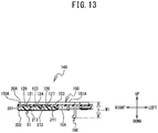
- the slots 211 to 213 may also be slots that have bottoms, as shown in FIG. 13 .
- the slots 211 to 213 may also be omitted from the absorption member 51.
- the nozzle cap 144 is provided in the left portion of the maintenance mechanism 141.
- the nozzle cap 144 is a cap that is rectangular in a plan view and is open at the top.
- the nozzle cap 144 is configured to move up and down. In a state in which the head unit 100 has moved over the nozzle cap 144, the nozzle cap 144 moves upward and covers the nozzle face 111. In this state, the ink purge operation is performed for the head unit 100.
- the ink that has accumulated in the nozzle cap 144 is thus discharged into a tank (not shown in the drawings) through a discharge channel that is not shown in the drawings.
- the flushing receiving portion 145 is positioned in the right part of the maintenance mechanism 141 and above a wall portion 74 (refer to FIG. 3 ) of a moving portion 63 that will be described later.
- the flushing receiving portion 145 is provided with a container portion 146 and a sponge 147.
- the container portion 146 is a container that is rectangular in a plan view and is open at the top.
- the sponge 147 is disposed inside the container portion 146 and is a three-dimensional rectangular member that is configured to absorb the ink.
- the flushing receiving portion 145 receives the ink that has been discharged from the head unit 100 by the flushing operation. The ink is absorbed by the sponge 147.
- the wiper 31 is disposed to the left of the flushing receiving portion 145.
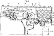
- the wiper 31 is configured to move up and down. In a state in which the wiper 31 has moved to its highest position, the moving of the carriage 20 in the left-right direction causes the wiper 31 to slide along the nozzle face 111. The wiper 31 thus removes the ink from the nozzle face 111 (refer to FIG. 6 ). In other words, the maintenance mechanism 141 performs the nozzle face wiping operation.
- the maintenance member 149 is disposed between the wiper 31 and the nozzle cap 144 in the left-right direction.
- the maintenance member 149 supports the absorption member 51.
- the wiper 31, a wiper support portion 32, a second spring support portion 61 (refer to FIG. 3 ), guide wall portions 801, 802 (refer to FIG. 5 ), and a wiper drive mechanism 58 are disposed in the non-printing area 140.
- the wiper 31 extends in the front-rear direction.
- the top edge of the wiper 31 is parallel to the nozzle face 111.
- the wiper support portion 32 is disposed on the bottom side of the wiper 31 and supports the wiper 31.
- the wiper support portion 32 When viewed from the left side, the wiper support portion 32 is formed into a rectangle whose long axis extends in the front-rear direction, and it has a specified width in the left-right direction (refer to FIG. 5 ). As shown in FIGS. 3 and 4 , the wiper support portion 32 is provided with a recessed portion 131 that is recessed downward. The lower portion of the wiper 31 is disposed inside the recessed portion 131.
- engagement portions 331, 332 are disposed on the bottom edges of the front and rear ends, respectively, of the wiper support portion 32.
- the engagement portions 331, 332 each have a recessed portion that is recessed upward, and inclined portions 641, 642, which will be described later, are disposed inside the respective recessed portions.
- the engagement portions 331, 332 engage with the inclined portions 641, 642, respectively, such that they can move in relation to the inclined portions 641, 642.
- a pair of first spring support portions 38 that are set apart from one another in the front-rear direction are disposed on the bottom edge of the wiper support portion 32.
- the pair of the first spring support portions 38 are hook-shaped and extend to the outside in the front-rear direction.
- the first spring support portions 38 support spring end portions 62 that are opposite ends of a single coil spring 60.
- the spring end portions 62 are formed into ring shapes, and they are hooked onto the hook-shaped first spring support portions 38.
- FIG. 4 shows the first spring support portion 38 on the rear side and also shows the spring end portion 62 on the rear side, which is hooked onto the first spring support portion 38 on the rear side.
- the second spring support portion 61 is positioned below the wiper support portion 32 in the up-down direction and between the pair of the first spring support portions 38 in the front-rear direction.
- a wall portion 79 supports the right end of the second spring support portion 61.
- the second spring support portion 61 is a metal plate that extends downward toward the left from the right end that is supported by the wall portion 79, and its tip is bent downward.
- the pair of the first spring support portions 38 support both ends of the coil spring 60. In a state in which the coil spring 60 is pulled downward, a central portion 603 of the coil spring 60 is hooked by the bottom face of the second spring support portion 61.
- the coil spring 60 assumes a V shape in which the central portion 603 is recessed downward.
- the coil spring 60 When the coil spring 60 is supported by the pair of the first spring support portions 38 and the second spring support portion 61, its resilience energizes the wiper support portion 32 downward.
- the coil spring 60 thus energizes the wiper 31 downward.
- the wiper support portion 32 moves up and down along the guide wall portions 801, 802 (refer to FIG. 5 ) in conjunction with the movements of the moving portion 63 in the left-right direction.
- the guide wall portions 801, 802 each extend in the up-down direction and are disposed along the contours of the front and rear edges of the wiper support portion 32 in a plan view.
- the guide wall portion 801 is provided with a pair of wall faces that face the left and right sides of the front end of the wiper support portion 32.
- the guide wall portion 802 is provided with a pair of wall faces that face the left and right sides of the rear end of the wiper support portion 32. Therefore, the guide wall portions 801, 802 may restrict the movement of the wiper support portion 32 in the left-right direction.
- the guide wall portions 801, 802 guide the up-down movements of the wiper 31 and the wiper support portion 32, specifically guiding them among a first contact position (refer to FIG. 6 ), a second contact position (refer to FIG. 4 ), and a withdrawn position (refer to FIG. 3 ).
- the first contact position is a position of the wiper 31 and the wiper support portion 32 in which the wiper 31 is able to be in contact with the nozzle face 111.
- the wiper support portion 32 is engaged with the upper ends of the inclined portions 641, 642 (described later).
- the second contact position is a position of the wiper 31 and the wiper support portion 32 in which the wiper 31 is able to be in contact with the absorption member 51.
- the wiper support portion 32 is engaged with the inclined portions 641, 642 (described later) slightly below their centers in the up-down direction. As shown in FIG.
- the withdrawn position is a position of the wiper 31 and the wiper support portion 32 in which the wiper 31 has withdrawn from both the nozzle face 111 and the absorption member 51.
- the wiper support portion 32 is engaged with the lower ends of the inclined portions 641, 642 (described later).
- the wiper drive mechanism 58 will be explained.
- the wiper drive mechanism 58 is a mechanism that moves the wiper 31 and the wiper support portion 32 up and down. As shown in FIG. 4 , the wiper drive mechanism 58 includes the moving portion 63 and a rotating member 78.
- the moving portion 63 is provided with a pair of opposite wall portions 651, 652 and the wall portion 74.
- the pair of the opposite wall portions 651, 652 face one another in the front-rear direction and are substantially triangular in a side view.
- the opposite wall portions 651, 652 are respectively provided with the inclined portions 641, 642.
- the pair of the inclined portions 641, 642 are disposed on the upper parts of the opposite wall portions 651, 652, respectively, and are components that extend obliquely downward toward the left.
- the inclined portions 641, 642 move the wiper 31 and the wiper support portion 32 in the up-down direction in conjunction with the movements of the moving portion 63 in the left-right direction.
- An extension portion 71 spans the gap between the lower ends of the inclined portions 641, 642.
- the extension portion 71 is plate-shaped and parallel to the horizontal plane.
- the wall portion 74 is a wall portion that is rectangular in a plan view. The left parts of both the front and the rear edges of the wall portion 74 are connected to the lower parts of the right edges of the opposite wall portions 651, 652, respectively.
- An oblong hole 75 is disposed in the right part of the wall portion 74. In a plan view, the oblong hole 75 has the same shape as an oblong hole 854 (refer to FIG. 5 ) that will be described later.
- the oblong hole 75 passes through the wall portion 74 in the up-down direction, with its long axis extending in the front-rear direction.
- the moving portion 63 moves in the left-right direction in conjunction with the rotation of the rotating member 78.
- the rotating member 78 is positioned below the wall portion 74.
- the rotating member 78 is rotated by the operation of a drive portion (not shown in the drawings) that will be described later.
- the rotating member 78 is provided with a rotating wall portion 781, a drive shaft 782, and a shaft portion 783.
- the rotating wall portion 781 is a wall portion that faces the wall portion 74 from below the wall portion 74.
- the rotating wall portion 781 is circular in a plan view.
- the drive shaft 782 extends in the up-down direction.
- the upper end of the drive shaft 782 is connected to the center of the bottom face of the rotating wall portion 781.
- the drive shaft 782 is connected to the drive portion (not shown in the drawings), which will be described later.
- the shaft portion 783 extends in the up-down direction.
- the lower end of the shaft portion 783 is connected to the outer circumferential portion of the top face of the rotating wall portion 781.
- the shaft portion 783 is positioned to the outside of the rotational center of the drive shaft 782.
- the shaft portion 783 is inserted through the oblong hole 75 in the same manner that a shaft portion 933 (refer to FIG. 5 ) is inserted through the oblong hole 854 (refer to FIG. 5 ), which will be described later.
- the maintenance member 149 is in an inclined state, having rotated clockwise in a front view from a mounted orientation, which is the orientation of the maintenance member 149 that is shown in FIG. 4 .
- the mounted orientation is an orientation in which the maintenance member 149 is parallel to the horizontal plane.
- the leftward direction and the rightward direction that are referenced when the maintenance member 149 as shown in FIG. 7 is explained are the same directions as when the maintenance member 149 is in the mounted orientation (refer to FIG. 4 ).
- the maintenance member 149 and an absorption drive mechanism 59 are disposed in the non-printing area 140.
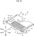
- the maintenance member 149 is provided with the upper plate 150, side walls 151, 152, the absorption member 51, engagement lugs 161, 162, and a locking projection portion 190.
- the upper plate 150 has a substantially rectangular plate shape that extends in the front-rear direction and the left-right direction.
- the upper plate 150 is provided with a right edge 150A, a left edge 150B, a front edge 150C, and a rear edge 150D.
- the direction from the front edge 150C to the rear edge 150D will be called the front-rear direction.
- the direction from the left edge 150B to the right edge 150A will be called the left-right direction.
- a recessed portion 181 that is recessed toward the right in a circular arc is provided in the left edge 150B.
- the side walls 151, 152 extend downward from the front and rear edges, respectively, of the upper plate 150.
- the side walls 151, 152 extend from slightly to the right of the left edge 150B of the upper plate 150 all the way to the right edge 150A of the upper plate 150.
- the lower edges of the side walls 151, 152 respectively form first projection portions 151B, 152B, which project downward.
- the upper edges of the side walls 151, 152 respectively form third projection portions 151A, 152A, which project upward.
- the first projection portions 151B, 152B project farther than an absorption face 202 of the absorption member 51 in the up-down direction.
- an upper face 153 is provided on the top side of the upper plate 150.
- a lower face 154 is provided on the bottom side of the upper plate 150.
- the upper face 153 and the lower face 154 are substantially rectangular faces that extend in the front-rear direction and the left-right direction of the upper plate 150.
- the color of the upper plate 150 may be gray, for example. Therefore, the color of the upper face 153 and the lower face 154 would also be gray.
- An allocated area 153A and an unallocated area 153B are disposed on the upper face 153, adjacent to one another in the left-right direction.
- the opening edge portion 120, the opening edge portion 123, and the opening edge portion 126 are located in the allocated area 153A, arrayed in that order starting from the right edge 150A side.
- the unallocated area 153B is an area in which no opening edge portions are located.
- the allocated area 153A is the area of the upper plate 150 from the center in the left-right direction to the right edge 150A.
- the allocated area 153A is located toward an edge face 201 side of the absorption member 51, which will be described later, from the center of the upper plate 150 in the left-right direction.
- the unallocated area 153B is the area of the upper plate 150 from the center in the left-right direction to the left edge 150B.
- the absorption member 51 is disposed on the lower face 154.
- the absorption member 51 is positioned on the lower face 154 side of the allocated area 153A and is not positioned on the lower face 154 side of the unallocated area 153B.
- the opening edge portions 120, 123, 126 are provided such that they each extend in the front-rear direction of the upper plate 150.
- the ends of the opening edge portions 120, 123, 126 in the front-rear direction each have circular arc shapes.
- the opening edge portion 120 forms an opening 121.
- the opening edge portion 123 forms an opening 124.
- the opening edge portion 126 forms an opening 127.
- the openings 121, 124, 127 are oblong holes whose long axes extend in the front-rear direction.
- the openings 121, 124, 127 are open clear through from the upper face 153 to the lower face 154. Therefore, the openings 121, 124, 127 are open clear through from the upper face 153 toward the absorption member 51.
- the opening edge portions 120, 123, 126 are disposed such that they each extend in the front-rear direction.
- the upper plate 150 is provided with inclined portions 122, 125, 128 that respectively encircle the opening edge portions 120, 123, 126.
- the inclined portions 122, 125, 128 incline from the upper face 153 toward the lower face 154 as they extend toward the opening edge portions 120, 123, 126.
- the right edge 150A is the edge on the right side of the upper plate 150 in the left-right direction of the lower face 154. As shown in FIG. 13 , in the thickness direction, the right edge 150A is positioned higher than the absorption face 202 of the absorption member 51, which will be described later.
- the thickness direction is the direction from the lower face 154 toward the upper face 153.
- the engagement lugs 161, 162 are lugs that respectively project toward the front from the front edge of the maintenance member 149 and toward the rear from the rear edge of the maintenance member 149.
- the engagement lugs 161, 162 respectively project from the side walls 151, 152 on the right edge 150A side in the allocated area 153A.
- the engagement lugs 161, 162 can respectively be mounted in and removed from engagement slots 921, 922 that will be described later (refer to FIGS. 8 and 14 ).
- a distance L11 (refer to FIG. 9 ) is the same as a distance L12 (refer to FIG. 8 ).
- the distance L11 is the distance between the pair of the engagement lugs 161, 162 in the front-rear direction.
- the distance L12 is the distance between the pair of the engagement slots 921, 922 in the front-rear direction. Note that the assertion that the distances L11, L12 are the same allows for sufficient difference between the distances L11, L12 for the maintenance member 149 to open and close when the engagement slots 921, 922 are respectively holding the engagement lugs 161, 162 such that the engagement lugs 161, 162 can rotate. For example, when the distance L11 is slightly less than the distance L12, the distances L11, L12 are regarded as being the same. As shown in FIGS. 9 , 10 , and 14 , the engagement lugs 161, 162 are each provided with flat faces 163, 164 and rounded faces 165, 166. As shown in FIG. 10 , a length L6 of the engagement lugs 161, 162 is greater than a length L7 of the engagement lugs 161, 162. The length L6 is the length in left-right direction. The length L7 is the length in the up-down direction.
- the flat faces 163, 164 of the engagement lugs 161, 162 are faces that are orthogonal to and connected with the side walls 151, 152, respectively, of the maintenance member 149.
- the flat faces 163, 164 are parallel to the absorption face 202 of the absorption member 51, which will be described later.
- the rounded faces 165, 166 are faces that are orthogonal to and connected with the side walls 151, 152, respectively, of the maintenance member 149.
- the rounded faces 165, 166 are connected to the edges of the corresponding flat faces 163, 164.
- the rounded faces 165, 166 of the engagement lugs 161, 162 have circular arc shapes that respectively conform to the shapes of the engagement slots 921, 922, which will be described later.
- the flat faces 163, the flat faces 164, the rounded faces 165, and the rounded faces 166 are respectively formed on the left faces, the right faces, the upper faces, and the lower faces of the engagement lugs 161, 162.
- the state in which the maintenance member 149 is oriented parallel to the vertical direction is a state in which the left-right direction of the upper plate 150 is parallel to the vertical direction and the engagement lugs 161, 162 are positioned on the lower side of the upper plate 150 in the vertical direction.
- the length L7 between the flat faces 163, 164 is shorter than a width L9 of an opening 923 in each of the engagement slots 921, 922.
- the length L6 between the rounded faces 165, 166 is longer than the width L9 of the opening 923 in each of the engagement slots 921, 922.
- the length L6 between the rounded faces 165, 166 is slightly shorter than a diameter L8 of each of the engagement slots 921, 922. Therefore, when the maintenance member 149 is in the mounted orientation, the engagement lugs 161, 162 do not come out of the engagement slots 921, 922.
- the locking projection portion 190 is a projection portion that is disposed in the unallocated area 153B and that projects downward, which is the direction from the lower face 154 toward the absorption member 51.
- the locking projection portion 190 is provided with a plate portion 191 and a locking claw 192.
- the plate portion 191 is provided such that it extends downward from the lower face 154.
- the locking claw 192 is located on the tip of the plate portion 191.
- the locking claw 192 locks to a locking portion 856 (refer to FIG. 14 ).
- the maintenance member 149 is thus secured in a closed state, as shown in FIGS. 3 and 4 .
- the maintenance member 149 rotates clockwise in a front view, with the engagement lugs 161, 162 that are positioned inside of the engagement slots 921, 922 serving as the axis of rotation.
- the maintenance member 149 rotates, the rounded faces 165, 166 of the engagement lugs 161, 162 slide along the inner faces of the engagement slots 921, 922, respectively.
- the maintenance member 149 thus enters the state in which it is oriented parallel to the vertical direction, as shown ins FIG. 14 .
- the length L7 between the flat faces 163, 164 of each of the engagement lugs 161, 162 is shorter than the width L9 of the opening 923 in each of the engagement slots 921, 922.
- the engagement lugs 161, 162 come out of the respective engagement slots 921, 922 through the openings 923 in the engagement slots 921, 922, as shown in FIG. 14 .
- the maintenance member 149 is thus removed from a mounting portion 85, which will be described later.
- the new maintenance member 149 is mounted in the mounting portion 85 by programming the steps described above in the reverse order.
- the absorption member 51 is affixed to the lower face 154 of the upper plate 150 of the maintenance member 149.
- the absorption member 51 has a substantially three-dimensional rectangular shape.
- the absorption member 51 is affixed to the lower face 154 side of the allocated area 153A (refer to FIG. 9 ), between the side walls 151, 152.
- the absorption member 51 is in contact with the side wall 152.
- a gap is provided between the absorption member 51 and the side wall 151.
- the absorption member 51 is formed from a material, such as a sponge, felt, or the like, that is configured to absorb a liquid.
- the absorption member 51 absorbs the ink that has adhered to the wiper 31.
- the absorption member 51 is provided with the edge face 201, which is the rectangular right side face on the right edge of the absorption member 51.
- the absorption member 51 is provided with the absorption face 202, which is the bottom face of the three-dimensional rectangular absorption member 51, on the bottom side, facing the wiper 31.
- the absorption member 51 is provided with an affixing face 204 (refer to FIG. 13 ) on the top face of the absorption member 51, on the opposite side of the absorption member 51 from the absorption face 202.
- the absorption member 51 is affixed by bringing the affixing face 204 into contact with the lower face 154 of the upper plate 150.
- the edge face 201 is exposed on the right edge 150A side of the upper plate 150. That is, the edge face 201 of the absorption member 51 is provided on the right edge 150A side of the upper plate 150, such that the edge face 201 extends parallel to the right edge 150A and orthogonal to the lower face 154. The edge face 201 extends in the front-rear direction of the upper plate 150.
- the absorption member 51 is affixed in the position where it covers each of the opening edge portions 120, 123, 126 in the lower face 154.
- the absorption member 51 is moistened by a liquid such as a moisturizing solution, water, or the like.
- the absorption face 202 may also be a flat face that extends in the front-rear and left-right directions.
- the absorption face 202 may also be provided with a plurality of grooves 211, 212, 213 that extend in the front-rear direction.
- the absorption drive mechanism 59 includes the mounting portion 85 and a rotating member 93.
- the maintenance member 149 is moved in the left-right direction by the operation of the absorption drive mechanism 59.
- the mounting portion 85 is a member on which the maintenance member 149 is mounted.
- the mounting portion 85 is provided with a first wall portion 851, a second wall portion 852, a third wall portion 853, and side walls 861, 862.
- the first wall portion 851 is rectangular, with its long axis extending in the front-rear direction, and it is a wall portion that forms the left end portion of the mounting portion 85.
- the first wall portion 851 is provided with the oblong hole 854.
- the oblong hole 854 passes through the first wall portion 851 in the up-down direction, with its long axis extending in the front-rear direction.
- the shaft portion 933 which will be described later, is inserted through the oblong hole 854.
- the second wall portion 852 which extends upward, is connected to the right edge of the first wall portion 851.
- a hole 855 whose long axis extends in the front-rear direction is disposed in the part where the first wall portion 851 and the second wall portion 852 are connected.
- the third wall portion 853 is connected to the upper edge of the second wall portion 852.
- the third wall portion 853 is rectangular in a plan view, with its long axis extending in the front-rear direction.
- the side walls 861, 862 extend upward from the front and rear edges, respectively, of the third wall portion 853, and they extend toward the right from the third wall portion 853.
- the engagement slots 921, 922 are disposed in the right end portions of the side walls 861, 862, respectively.
- the engagement slots 921, 922 pass through the side walls 861, 862, respectively, in the front-rear direction.
- the openings 923 in the engagement slots 921, 922 are open upward, on the side toward the head 110.
- the engagement slots 921, 922 are circular in a side view, for example.
- the upper edges of the engagement slots 921, 922 are the openings 923, which are open upward.
- the engagement lugs 161, 162 are disposed inside the engagement slots 921, 922, respectively.
- the engagement slots 921, 922 do not necessarily have to extend through the side walls 861, 862, as long as the engagement lugs 161, 162 can be disposed inside the engagement slots 921, 922.
- the mounting portion 85 moves in the left-right direction in conjunction with the rotation of the rotating member 93.
- the rotating member 93 is disposed below the first wall portion 851, the second wall portion 852, and the third wall portion 853 of the mounting portion 85.
- the rotating member 93 is provided with a rotating wall portion 931, a drive shaft 932 (refer to FIG. 4 ), and the shaft portion 933.
- the rotating wall portion 931 is a wall portion that is substantially circular in a plan view.
- the drive shaft 932 extends in the up-down direction, and its upper end is connected to the center of the bottom face of the rotating wall portion 931.
- the drive shaft 932 is connected to the drive portion (not shown in the drawings), which includes a motor, a gear, and the like.
- the drive shaft 932 rotates the rotating wall portion 931 by rotating in conjunction with the operation of the drive portion (not shown in the drawings).
- the shaft portion 933 extends in the up-down direction, and its lower end is connected to the outer circumferential portion of the top face of the rotating wall portion 931.
- the shaft portion 933 is positioned to the outside of the rotational center of the drive shaft 932 and is inserted through the oblong hole 854.
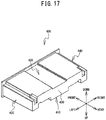
- the maintenance member 149 is provided with a protection plate 410.
- the protection case 400 is a case that contains the maintenance member 149 and protects the absorption member 51.
- the left, right, upper left, lower right, upper right, and lower left sides in FIG. 15 will be called the front, rear, up, down, right, and left sides of the protection case 400.
- the protection case 400 is a substantially rectangular box in which an opening 401 is open to the front side.
- the protection case 400 may be formed from a resin material, for example.
- the protection case 400 is provided with the protection plate 410, a bottom plate 420, a left side wall 430, a right side wall 440, and a rear wall 450 (refer to FIG. 17 ).
- the protection plate 410 is substantially rectangular in a plan view and is provided with a top face 410A, a protection face 410B, and a front edge portion 410C.
- the top face 410A is the face on the top side of the protection plate 410, and it has raised and recessed portions.
- the protection face 410B is the face on the bottom side of the protection plate 410. As shown in FIG. 20 , when the maintenance member 149 is stored correctly in the protection case 400, the protection face 410B faces the absorption face 202 of the absorption member 51.
- first opposite projection portions 411, 412, first recessed portions 413, 414, a second recessed portion 415, and third recessed portions 417, 418 are disposed in the protection face 410B of the protection plate 410.
- the first opposite projection portions 411, 412 are a left-right pair.
- the first opposite projection portions 411, 412 reside in positions where they are respectively opposite the first projection portions 151B, 152B (refer to FIG. 11 ).
- the first projection portions 151B, 152B are respectively the lower edges of the side walls 151, 152 of the maintenance member 149.
- the first opposite projection portions 411, 412 are the parts that project farthest downward from the protection face 410B.
- the bottom faces of the first opposite projection portions 411, 412 extend parallel to the front-rear direction of the protection plate 410 from the front edge portion 410C to the rear wall 450.
- the first recessed portions 413, 414 are a left-right pair that are located between the first opposite projection portions 411, 412.
- the bottom faces of the first recessed portions 413, 414 are recessed upward such that they are higher than the first opposite projection portions 411, 412.
- the bottom faces of the first recessed portions 413, 414 extend parallel to the front-rear direction of the protection plate 410 from the front edge portion 410C to the rear wall 450.
- the second recessed portion 415 is located between the first recessed portions 413, 414.
- the bottom face of the second recessed portion 415 is recessed upward such that it is higher than the bottom faces of the first recessed portions 413, 414.
- the bottom face of the second recessed portion 415 extends parallel to the front-rear direction of the protection plate 410 from the front edge portion 410C to the rear wall 450.
- the third recessed portions 417, 418 are located to the outside of the first opposite projection portions 411, 412 on the left and right, respectively.
- the expression “to the outside on the left and right” means in the leftward direction and the rightward direction from the center in the left-right direction of the protection plate 410.
- the expression “to the inside on the left and right” would mean toward the center in the left-right direction of the protection plate 410.
- the bottom faces of the third recessed portions 417, 418 are recessed upward such that they are higher than the first opposite projection portions 411, 412.
- the bottom faces of the third recessed portions 417, 418 extend parallel to the front-rear direction of the protection plate 410 from the front edge portion 410C to the rear wall 450.
- the bottom faces of the third recessed portions 417, 418 are recessed upward such that they are higher than the bottom faces of the first recessed portions 413, 414.
- a recessed portion 416 that is recessed toward the rear is located in the front edge portion 410C of the protection plate 410.
- the recessed portion 416 is recessed such that the locking projection portion 190 of the maintenance member 149 will not come into contact with the front edge portion 410C.
- the bottom plate 420 is substantially rectangular in a plan view. As shown in FIG. 18 , the bottom plate 420 is provided with a front edge portion 420A.
- the protection case 400 is provided with the rear wall 450, which extends from the protection plate 410 to the bottom plate 420. As shown in FIGS. 18 and 19 , the rear wall 450 is provided with a left-right pair of engaged portions 460, 465.
- the engaged portions 460, 465 project from the rear wall 450 toward the front of the protection plate 410.
- the engaged portions 460, 465 are configured to flex in an extension direction of the rear wall 450. As shown in FIG.
- the engaged portion 460 is provided with a plate portion 461 that extends toward the front by a specified distance.
- a locked claw 462 is located on the tip of the plate portion 461.
- the engaged portion 465 has the same structure. The engaging of the locked claw 462 with the engagement lug 162 of the maintenance member 149 allows the protection case 400 to secure the maintenance member 149 such that the maintenance member 149 can be inserted and removed.
- the locked claw 462 of the engaged portion 465 engages with the engagement lug 161 in the same manner.
- the engaged portions 465, 460 are located to the outside of the first opposite projection portions 411, 412 on the left and right, respectively.
- the rear wall 450 is provided with ribs 451, 452, 453, 454.
- the ribs 451, 452, 453, 454 are provided such that they project toward the front from the rear wall 450 and extend in the up-down direction.
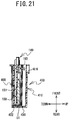
- FIG. 21 when the maintenance member 149 has been stored in the protection case 400, the right edge 150A of the upper plate 150 of the maintenance member 149 is in contact with the ribs 451, 452, 453, 454.
- the bottom plate 420 is provided with a left-right pair of fourth recessed portions 421, 422.
- the top faces of the fourth recessed portions 421, 422 are recessed downward.
- the top faces of the fourth recessed portions 421, 422 extend parallel to the front-rear direction of the protection plate 410 from the front edge portion 420A to the rear wall 450.
- the fourth recessed portions 421, 422 face upward toward the third projection portions 151A, 152A, respectively.
- the distance between the left edge of the fourth recessed portion 421 and the right edge of the fourth recessed portion 422 is greater than the distance between the third projection portions 151A, 152A.
- the storing of the maintenance member 149 in the protection case 400 A case in which the maintenance member 149 is stored correctly in the protection case 400, as shown in FIG. 20 , will be explained.
- the maintenance member 149 that is shown in FIG. 11 is inserted into the opening 401 of the protection case 400 that is shown in FIG. 16 , starting from the right edge 150A of the upper plate 150.
- the maintenance member 149 is inserted into the opening 401 such that the protection face 410B of the protection plate 410 is opposite the lower face 154 of the upper plate 150.
- the locking projection portion 190 of the maintenance member 149 enters the recessed portion 416 of the protection case 400. Therefore, the locking projection portion 190 does not come into contact with the front edge portion 410C of the protection plate 410.
- the maintenance member 149 is inserted into the protection case 400 until the edge of the maintenance member 149 comes into contact with the ribs 451, 452, 453, 454 (refer to FIG. 18 ).
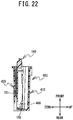
- the engagement lug 162 of the maintenance member 149 engages with the engaged portion 460, as shown in FIG. 22 .
- the engagement lug 161 engages with the engaged portion 465 in the same manner.
- the protection case 400 thus secures the maintenance member 149 in its stored state.
- the first opposite projection portions 411, 412 of the protection plate 410 are respectively positioned opposite the first projection portions 151B, 152B of the maintenance member 149 (refer to FIG. 11 ).
- the absorption face 202 of the absorption member 51 is positioned opposite the first recessed portions 413, 414 and the second recessed portion 415 (refer to FIG. 15 ).
- the first projection portions 151B, 152B project farther than the absorption face 202 of the absorption member 51 in the up-down direction.
- the first opposite projection portions 411, 412 come into contact with the first projection portions 151B, 152B of the maintenance member 149 before the protection face 410B comes into contact with the absorption member 51.
- a space is formed between the protection face 410B and the absorption face 202 of the absorption member 51. It is therefore possible to prevent the protection face 410B from pressing on the absorption member 51. The possibility that liquid will seep out of the absorption member 51 may thus be decreased.
- the maintenance member 149 is inserted into the protection case 400 such that the protection face 410B of the protection plate 410 is opposite the upper face 153 of the upper plate 150.
- the lower face 154 of the maintenance member 149 faces the bottom plate 420.
- the locking projection portion 190 is on the lower face 154, but the bottom plate 420 does not have a recessed portion to avoid contact with the locking projection portion 190. Therefore, the locking projection portion 190 comes into contact with the front edge portion 420A of the bottom plate 420.
- the maintenance member 149 cannot be inserted far enough into the protection case 400 to come into contact with the ribs 451, 452, 453, 454.
- the engagement lug 162 of the maintenance member 149 cannot engage with the engaged portion 460.
- the engagement lug 161 cannot engage with the engaged portion 465.
- the maintenance member 149 thus enters a state in which it is positioned farther toward the front than when it is in the correct state that is shown in FIG. 20 . In this position, the maintenance member 149 is not be secured in the protection case 400. Therefore, it may be easy for the operator to notice that the maintenance member 149 is not stored correctly in the protection case 400.
- a distance W1 (refer to FIG.
- the distance W1 is the distance from the third projection portions 151A, 152A of the upper plate 150 to the locking projection portion 190.
- the distance W3 is the distance from the lower faces of the first opposite projection portions 411, 412 to the upper faces of the fourth recessed portions 421, 422, respectively.
- a distance W2 (refer to FIG. 18 ) needs only to be not less than the distance W1, for example.
- the distance W2 is the distance from the lower face of the second recessed portion 415 to the upper faces of the fourth recessed portions 421, 422. For example, the condition that W3 ⁇ W1 ⁇ W2 needs to be satisfied.
- the protection plate 410 Because the protection plate 410 is fixed in place with a gap between it and the absorption member 51, the protection plate 410 protects the absorption member 51.
- the protection plate 410 When external pressure bears on the protection plate 410, for example, the protection face 410B can be prevented from pressing on the absorption member 51. Therefore, the possibility that liquid will seep out of the absorption member 51 may be decreased.
- the space between the pair of the first opposite projection portions 411, 412 is recessed upward higher than the first opposite projection portions 411, 412.
- This recessed area is formed by the first recessed portions 413, 414 and the second recessed portion 415, for example.
- the maintenance member 149 is oriented such that the absorption member 51 is opposite this recessed area.
- the engagement lugs 161, 162 of the upper plate 150 respectively engage with the engaged portions 465, 460 of the protection plate 410.
- This structure may protect the absorption member 51 by decreasing the possibility that the upper plate 150 of the maintenance member 149 will move away from the protection plate 410 when the protection case 400 is dropped, for example.
- the engaged portions 460, 465 flex in the extension direction of the rear wall 450. Therefore, the engagement lugs 161, 162 of the upper plate 150 may engage easily with the engaged portions 465, 460 of the protection plate 410 by the force that acts on the maintenance member 149 when the maintenance member 149 is inserted into the protection case 400.
- the engaged portions 460, 465 are located to the outside of the first opposite projection portions 411, 412. Therefore, the distance between the engaged portion 460 and the engaged portion 465 is greater than it would be if the engaged portions 460, 465 were located to the inside of the first opposite projection portions 411, 412. Because the engaged portions 460, 465 are separated by a substantial distance, they may hold the upper plate 150 of the maintenance member 149 in a stable manner.
- the third recessed portions 417, 418 are located in the protection plate 410 to the outside of the first opposite projection portions 411, 412, respectively, and are recessed upward higher than the first opposite projection portions 411, 412. This structure may ensure a greater range of flexure for the engaged portions 460, 465.
- the ribs 451, 452, 453, 454 are configured to ensure a distance between the rear wall 450 and the right edge 150A of the upper plate 150. This structure may make it possible for the engaged portions 460, 465 to be made longer in the direction in which the protection face 410B extends. The force that flexes the engaged portions 460, 465 thus becomes less than it would be if the engaged portions 460, 465 were shorter. Therefore, it may be easy for the engagement lugs 161, 162 of the upper plate 150 to engage with and disengage from the engaged portions 465, 460 of the protection plate 410.
- the length L6 in the left-right direction of the engagement lugs 161, 162 is greater than the length L7 in the up-down direction of the engagement lugs 161, 162. Therefore, the maintenance member 149 may be mounted in and removed from the device by rotating the maintenance member 149.
- the locking projection portion 190 does not come into contact with the protection plate 410.
- the maintenance member 149 may therefore fit into the protection case 400.
- the first projection portions 151B, 152B and the first opposite projection portions 411, 412 are disposed on opposite sides of the upper plate 150, the locking projection portion 190 does come into contact with the bottom plate 420. Therefore, the maintenance member 149 cannot fit into the protection case 400.
- the maintenance member 149 cannot fit into the protection case 400 when the upper plate 150 is not in the correct orientation. Therefore, the operator may be prevented from fitting the maintenance member 149 into the protection case 400 incorrectly.
- the bottom plate 420 is recessed across a wider span than the distance between the third projection portions 151A, 152A. Because the bottom plate 420 is recessed across a wide span, it may accommodate the third projection portions 151A, 152A. The maintenance member 149 may therefore fit into the protection case 400.
- the printer 1 is an example of a print device of the present invention.
- the head 110 is an example of a print head of the present invention.
- the nozzle face 111 is an example of a nozzle formation face of the present invention.
- the upper plate 150 is an example of a plate of the present invention.
- the lower face 154 is an example of a first face of the present invention.
- the upper face 153 is an example of a second face of the present invention.
- the engagement lugs 161, 162 are examples of engagement portions of the present invention.
- the right edge 150A is an example of a plate edge of the present invention.
- the rear wall 450 is an example of a wall extending from the protection face of the present invention.
- the locking projection portion 190 is an example of a second projection portion of the present invention.
- the left-right direction of the upper face 153 is identical to the left-right direction of the lower face 154, as shown in FIG. 10 and the like, and is an example of an extension direction of the first face of the present invention.
- the front-rear direction of the protection plate 410 is identical to the front-rear direction of the protection face 410B, as shown in FIG. 16 and the like, and is an example of an extension direction of the protection face 410B of the present invention.
- the affixing face 204 is an example of an opposite face of the present invention.
- the absorption face 202 is an example of an exposed face of the present invention.
- the structure that protects the absorption member 51 is not limited to a box-shaped object like the protection case 400, and it may also be a plate-shaped protection plate 470, as shown in FIG. 24 .
- the protection plate 470 is substantially rectangular in a plan view, and it is provided with a protection face 471, a pair of wall portions 476, 476, a pair of engagement portions 474, 475, and lugs 477 to 480.
- the protection face 471 is a flat surface that is substantially rectangular in a plan view.
- the wall portions 476, 476 have specified heights and extend along the front and rear edges of the protection face 471.
- the wall portions 476, 476 extend in the left-right direction.
- the lugs 477 to 480 have specified heights and are provided at the left and right ends of the protection face 471.
- the engagement portions 474, 475 rise vertically from the right and left ends, respectively, of the protection face 471.
- the protection plate 470 is fixed in place such that the protection face 471 faces the absorption face 202 of the absorption member 51 of the maintenance member 149 that is shown in FIG. 11 .
- the engagement portions 474, 475 engage with the side walls 151, 152 of the upper plate 150.
- the lugs 477, 478, 479, 480 form a space between the protection face 471 and the absorption face 202 of the absorption member 51.
- the wall portions 476, 476 protect the edge face 201 of the absorption member 51 and the edge face of the absorption member 51 on the opposite side from the edge face 201.
- the protection plate 410 is provided with the first recessed portions 413, 414 and the second recessed portion 415, but the first recessed portions 413, 414 and the second recessed portion 415 may also be a single recessed portion.
- the engaged portions 460, 465 are provided on the rear wall 450, but the engaged portions 460, 465 may instead be provided on the right side wall 440 and the left side wall 430, respectively. In that case, the rear wall 450 may be omitted from the protection case 400. It is also acceptable for the upper plate 150 not to be provided with the first projection portions 151B, 152B. It is also acceptable for the upper plate 150 not to be provided with the third projection portions 151A, 152A.
- the bottom plate 420 not to be provided with the fourth recessed portions 421, 422.
- the protection plate 410 not to be provided with the first opposite projection portions 411, 412 in positions that are opposite the first projection portions 151B, 152B.
- the upper plate 150 may also be provided with one each of the first projection portion and the first opposite projection portion. It is also acceptable for the upper plate 150 not to be provided with the locking projection portion 190. It is also acceptable for the upper plate 150 not to be provided with the engagement lugs 161, 162. In that case, the upper plate 150 may be held by an engagement portion that is provided in the housing 2. It is also acceptable for only one of the engaged portions 460, 465 to be provided on the rear wall 450.
- the rear wall 450 may also be provided with any number of ribs, such as one, two, three, or the like.
Landscapes
- Ink Jet (AREA)
Abstract
Description
- The present invention relates to a maintenance member that is configured to anchor to a plate an absorption member that absorbs ink.
- An inkjet printer is known that is provided with a wiper and a liquid recovery part. The wiper removes a liquid, such as an ink or the like, from a nozzle forming surface on which a nozzle is formed. The liquid recovery part recovers the liquid, such as an ink or the like, that has been scraped off by the wiper. For example,
Japanese Laid-Open Patent Publication No. 2015-33784 - In the inkjet printer that is described in
Japanese Laid-Open Patent Publication No. 2015-33784 - It is an object of the present invention to provide a maintenance member that may reduce the possibility that a liquid will seep out of a liquid absorption material that absorbs a liquid.
- A maintenance member of the present invention includes a plate, an absorption member, a plate edge, opening edge portions, and a protection plate. The plate includes a first face and a second face disposed on the opposite side from the first face. The absorption member is configured to absorb ink. The absorption member includes an opposite face and an exposed face. The opposite face opposes the first face. The exposed face is disposed on the opposite side from the opposite face. The absorption member is disposed on the first face and has absorbed a liquid. The plate edge is located in a thickness direction from the exposed face. The thickness direction is the direction from the first face toward the second face. The plate edge is an edge of the plate on the side of the plate in an extension direction of the first face. The opening edge portions are located in the plate and are opening toward the absorption member from the second face. The protection plate is fixed in place such that a gap is provided between the protection plate and the absorption member. The protection plate is configured to protect the absorption member from contact. For example, the protection plate protects the absorption member when the maintenance member is stored. Because a space is provided between the protection plate and the absorption member, it is possible, for example, to prevent an external pressure that presses on the protection plate from pressing on the absorption member. Therefore, the possibility that the liquid will seep out of the absorption member may be decreased.
- In the maintenance member, the plate may be configured to be mounted in a print device. The print device may be configured to recover ink adhering to a wiper. The wiper may be configured to wipe off ink adhering to a nozzle formation face of a print head. The print head may be configured to discharge ink. Therefore, the absorption member may recover ink that has adhered to the wiper.
- In the maintenance member, the plate may include a first projection portion projecting farther than the absorption member on the first face. Therefore, the first projection portion may ensure the space between the absorption member and the protection plate.
- In the maintenance member, the protection plate may include a first opposite projection portion in a position opposite the first projection portion. Therefore, the first opposite projection portion may ensure the space between the absorption member and the protection plate.
- In the maintenance member, the protection plate may include a pair of the first opposite projection portions, with a space between the pair of the first opposite projection portions. The space may be recessed in relation to the pair of the first opposite projection portions. Therefore, the absorption member may be disposed in the recessed space between the pair of the first opposite projection portions.
- In the maintenance member, the plate may include an engagement portion projecting in an orthogonal direction orthogonal to the extension direction of the first face in the first face. The protection plate may include a protection face and a wall. The protection face may oppose the absorption member. The wall may extend from the protection face in a direction crossing the protection face. The wall may include an engaged portion. The engaged portion may project in an extension direction of the protection face and be configured to engage with the engagement portion. The engaged portion may be configured to engage with the engagement portion by flexing in an extension direction of the wall. Therefore, this structure may protect the absorption member, because the plate does not readily fall off when the maintenance member is dropped, for example.
- In the maintenance member, the plate may include a first projection portion projecting farther than the absorption member on the first face. The protection plate may include a first opposite projection portion in a position opposite the first projection portion. The engaged portion may be disposed to the outside from the first opposite projection portion. Therefore, the engaged portion, being set apart by a specified distance, may hold the plate in a stable manner. The outside in the orthogonal direction may correspond to one direction or the other direction in the orthogonal direction from the center in the orthogonal direction. The inside in the orthogonal direction may correspond to any direction in the orthogonal direction toward the center in the orthogonal direction. The first opposite projection portion may also be disposed between the engaged portion and the absorption member in the extension direction of the first face.
- In the maintenance member, the area to the outside from the first opposite projection portion may be recessed in relation to the first opposite projection portion. Therefore, the recessed area to the outside from the first opposite projection portion may ensure a greater range of flexure for the engaged portion.
- In the maintenance member, the wall may include a pair of the engaged portions. The wall may include at least one rib between the pair of the engaged portions. Therefore, the at least one rib may make it easy for the pair of the engagement portions to engage with and disengage from the pair of the engaged portions.
- In the maintenance member, the length of the engagement portion in the extension direction of the first face may be greater than the length of the engagement portion in a thickness direction of the engagement portion. The thickness direction of the engagement portion may be orthogonal to the extension direction of the first face and to the orthogonal direction. Therefore, the maintenance member may be mounted in and removed from a device by rotating the maintenance member.
- In the maintenance member, the protection plate may include a bottom plate disposed such that a gap is provided between the protection plate and the bottom plate. The plate may include a pair of the first projection portions and a second projection portion. The second projection portion may be disposed between the pair of the first projection portions. The second projection portion may project in the same direction as the pair of the first projection portions. The second projection portion may not come into contact with the protection plate in a state in which the pair of the first opposite projection portions oppose the pair of the first projection portions. The second projection portion may come into contact with the bottom plate in a state in which the pair of the first opposite projection portions and the pair of the first projection portions are on opposite sides of the plate. Therefore, the operator may be prevented from mounting the maintenance member by mistake when the plate is not oriented correctly.
- In the maintenance member, the plate may include a pair of third projection portions projecting from the second face of the plate. The bottom plate may be recessed across a wider space than the space between the pair of the third projection portions. Therefore, the pair of the third projection portions may be disposed on the bottom plate, which is recessed across a wide space.
- Embodiments will be described below in detail with reference to the accompanying drawings in which:
-
FIG. 1 is an oblique view of a printer 1; -
FIG. 2 is a plan view of the printer 1; -
FIG. 3 is a section view, as seen from the direction of arrows A-A inFIG. 2 , in which awiper 31 is in a withdrawn position and anabsorption member 51 is in a first position; -
FIG. 4 is a section view of the printer 1 in which thewiper 31 is in a second contact position and theabsorption member 51 is in the first position; -
FIG. 5 is a plan view of amaintenance mechanism 141, from which amaintenance member 149 has been removed; -
FIG. 6 is a section view of the printer 1 in which thewiper 31 is in a first contact position and a nozzle face wiping operation is performed; -
FIG. 7 is an oblique view of themaintenance mechanism 141, in which themaintenance member 149 is in an inclined state; -
FIG. 8 is a plan view of themaintenance mechanism 141, with themaintenance member 149 mounted; -
FIG. 9 is a plan view of themaintenance member 149; -
FIG. 10 is an oblique view of themaintenance member 149, as seen obliquely from above; -
FIG. 11 is an oblique view of themaintenance member 149, as seen obliquely from below; -
FIG. 12 is a bottom view of themaintenance member 149; -
FIG. 13 is a section view of themaintenance member 149, as seen from the direction of arrows A-A inFIG. 9 ; -
FIG. 14 is a figure for explaining mounting and removal of themaintenance member 149; -
FIG. 15 is an oblique view of aprotection case 400, as seen obliquely from the front and below; -
FIG. 16 is an oblique view of theprotection case 400, as seen obliquely from the front and above; -
FIG. 17 is an oblique view of theprotection case 400, as seen obliquely from the rear and above; -
FIG. 18 is a front view of theprotection case 400; -
FIG. 19 is a section view of theprotection case 400, as seen from the direction of arrows B-B inFIG. 18 ; -
FIG. 20 is an oblique view of a state in which themaintenance member 149 is stored correctly in theprotection case 400; -
FIG. 21 is a section view of theprotection case 400 and themaintenance member 149, as seen from the direction of arrows C-C inFIG. 20 ; -
FIG. 22 is a section view of theprotection case 400 and themaintenance member 149, as seen from the direction of arrows D-D inFIG. 20 ; -
FIG. 23 is an oblique view of a state in which themaintenance member 149 is housed in theprotection case 400 with the orientations of anupper face 153 and alower face 154 reversed; and -
FIG. 24 is an oblique view of aprotection plate 470 in a modified example. - The configuration of a printer 1 will be explained with reference to
FIGS. 1 to 8 . In the explanation that follows, the terms left, right, front, rear, up, and down that are used are those indicated by the arrows in the drawings. - As shown in
FIG. 1 , the printer 1 is an inkjet printer that prints by discharging an ink that is an example of a liquid onto a cloth such as a T-shirt or the like (not shown in the drawings) that is a printing medium. The printing medium may also be a paper or the like. The printer 1 is configured to print a color image on the printing medium by discharging downward five different types of the ink (white, black, yellow, cyan, and magenta), for example. In the explanation that follows, among the five different types of the ink, the ink that is white will be called the white ink. The other four types of the ink, black, yellow, cyan, and magenta, will be collectively called the color inks. - The printer 1 is provided with a
housing 2, aplaten drive mechanism 6, a pair of guide rails (not shown in the drawings), aplaten 5, a tray 4, aframe body 10, ashaft 9, arail 7, acarriage 20,head units drive belt 101, and adrive motor 19. - An operation portion (not shown in the drawings) that performs operations of the printer 1 is disposed on the front side of the right portion of the
housing 2. The operation portion is provided with a display and operation buttons. An operator operates the operation buttons when inputting commands that are related to various types of operations of the printer 1. - The
frame body 10 has a frame shape that is substantially rectangular in a plan view, and it is installed in the top portion of thehousing 2. The front side of theframe body 10 supports theshaft 9. The rear side of theframe body 10 supports therail 7. Theshaft 9 extends in the left-right direction on the inner side of theframe body 10. Therail 7 is disposed opposite theguide shaft 9 and extends in the left-right direction. - The
carriage 20 is configured to be conveyed to the left and the right along theshaft 9. As shown inFIGS. 1 and2 , thehead units carriage 20. Thehead unit 100 is disposed in front of thehead unit 200. As shown inFIG. 3 , ahead 110 is disposed on the bottom of each one of thehead units nozzle face 111 is disposed on the bottom face of the each of theheads 110. Thenozzle face 111 is flat and parallel to the horizontal plane.FIG. 3 shows thehead 110 and thenozzle face 111 on thehead unit 100. A plurality of nozzles are disposed in thenozzle face 111 that are configured to discharge one of the white ink and the color inks downward. - As shown in
FIG. 1 , thedrive belt 101 spans the inner side of theframe body 10 in the left-right direction. Thedrive motor 19 is provided in the front right portion of the inner side of theframe body 10. Thedrive motor 19 is coupled to thecarriage 20 through thedrive belt 101. As thedrive motor 19 drives thedrive belt 101, thecarriage 20 moves reciprocally in the left-right direction (a main scanning direction) along theguide shaft 9. As thehead units head units platen 5, which is disposed such that it faces thehead units - The
platen drive mechanism 6 is provided with the pair of the guide rails (not shown in the drawings) and a platen support base (not shown in the drawings). The pair of the guide rails extend in the front-rear direction on the inner side of theplaten drive mechanism 6. The pair of the guide rails support the platen support base such that it can move toward the front and the rear. The top portion of the platen support base supports theplaten 5. Theplaten 5 supports the printing medium. - The tray 4 is disposed below the
platen 5. In a case where the printing medium is a T-shirt, for example, the tray 4 receives the sleeves and the like of the T-shirt when the operator places the T-shirt on theplaten 5. The tray 4 thus protects sleeves and the like, such that they do not come into contact with other parts in the interior of thehousing 2. - An auxiliary scanning direction drive portion (not shown in the drawings) drives the
platen drive mechanism 6. When theplaten drive mechanism 6 is thus driven, it moves the platen support base and theplaten 5 toward the front and the rear of thehousing 2 along the pair of the guide rails. As theplaten 5 conveys the printing medium in the front-rear direction (an auxiliary scanning direction), theheads 110 discharge the inks as they move reciprocally in the left-right direction. The printer 1 thus performs printing on the printing medium. - As shown in
FIGS. 1 and2 , along the path that theheads 110 travel, the area where theheads 110 perform printing will be called theprinting area 130. The area along the path that theheads 110 travel that is outside theprinting area 130 will be called thenon-printing area 140. Thenon-printing area 140 is an area in the left portion of the printer 1. Theprinting area 130 is the area from the right edge of thenon-printing area 140 to the right end of the printer 1. Theplaten 5, the tray 4, and the like are disposed in theprinting area 130. - Various types of maintenance operations for ensuring printing quality are performed in the
non-printing area 140. For example, the maintenance operations include a flushing operation, an ink purge operation, a nozzle face wiping operation, a wiper wiping operation, and the like. The flushing operation is an operation that, before printing is performed on the printing medium, discharges the inks from theheads 110 onto a flushing receiving portion 145 (refer toFIG. 2 ) that will be described later. The flushing operation makes it possible for the inks to be discharged appropriately from theheads 110, even right after the printing starts. The ink purge operation is an operation in which the nozzle faces 111 are capped by nozzle caps 144 (refer toFIG. 2 ) that will be described later and the inks are pulled out of the nozzles by suction devices (not shown in the drawings) that are connected to the nozzle caps 144. The ink purge operation discharges, along with the ink, any air bubbles that have gotten inside the nozzles, for example. It is therefore possible to decrease the possibility that the air bubbles will cause an ink discharge problem to occur. - The nozzle face wiping operation is an operation in which wipers 31 wipe off excess ink that is remaining on the surfaces of the nozzle faces 111 (refer to
FIG. 6 ). When the ink that is remaining on nozzle faces 111 hardens and binds to the nozzle faces 111, there is a possibility that it will become difficult for the nozzles to discharge the inks. That possibility can be decreased by the nozzle face wiping operation. The wiper wiping operation is an operation in which absorption members 51 (refer toFIG. 3 ) that will be described later wipe off ink that is adhering to thewipers 31. In a state in which the ink that has been wiped off of the nozzle faces 111 is adhering to thewipers 31, there is a possibility that the ink from thewipers 31 will adhere to the nozzle faces 111 the next time that the nozzle face wiping operation is performed. That possibility can be decreased by the wiper wiping operation. - As shown in
FIG. 2 ,maintenance mechanisms non-printing area 140. Themaintenance mechanisms head units maintenance mechanisms head units maintenance mechanisms maintenance mechanism 141 will be explained. - As shown in
FIGS. 2 and3 , themaintenance mechanism 141 is provided with thewiper 31, thenozzle cap 144, theflushing receiving portion 145, and amaintenance member 149. The section views inFIGS. 3 ,4 , and6 do not show openingedge portions upper plate 150 of themaintenance member 149. As shown inFIGS. 9 and10 , the openingedge portions upper plate 150. In the section views inFIGS. 3 ,4 , and6 ,slots 211 to 213 that are disposed in theabsorption member 51 are through-holes (refer toFIG. 7 ). Theslots 211 to 213 may also be slots that have bottoms, as shown inFIG. 13 . Theslots 211 to 213 may also be omitted from theabsorption member 51. Thenozzle cap 144 is provided in the left portion of themaintenance mechanism 141. Thenozzle cap 144 is a cap that is rectangular in a plan view and is open at the top. Thenozzle cap 144 is configured to move up and down. In a state in which thehead unit 100 has moved over thenozzle cap 144, thenozzle cap 144 moves upward and covers thenozzle face 111. In this state, the ink purge operation is performed for thehead unit 100. The ink that has accumulated in thenozzle cap 144 is thus discharged into a tank (not shown in the drawings) through a discharge channel that is not shown in the drawings. - As shown in
FIG. 3 , theflushing receiving portion 145 is positioned in the right part of themaintenance mechanism 141 and above a wall portion 74 (refer toFIG. 3 ) of a movingportion 63 that will be described later. Theflushing receiving portion 145 is provided with acontainer portion 146 and asponge 147. Thecontainer portion 146 is a container that is rectangular in a plan view and is open at the top. Thesponge 147 is disposed inside thecontainer portion 146 and is a three-dimensional rectangular member that is configured to absorb the ink. Theflushing receiving portion 145 receives the ink that has been discharged from thehead unit 100 by the flushing operation. The ink is absorbed by thesponge 147. - As shown in
FIGS. 2 and3 , thewiper 31 is disposed to the left of theflushing receiving portion 145. Thewiper 31 is configured to move up and down. In a state in which thewiper 31 has moved to its highest position, the moving of thecarriage 20 in the left-right direction causes thewiper 31 to slide along thenozzle face 111. Thewiper 31 thus removes the ink from the nozzle face 111 (refer toFIG. 6 ). In other words, themaintenance mechanism 141 performs the nozzle face wiping operation. - The
maintenance member 149 is disposed between thewiper 31 and thenozzle cap 144 in the left-right direction. Themaintenance member 149 supports theabsorption member 51. - The configuration that supports the
wiper 31 and moves it up and down will be explained. As shown inFIGS. 3 to 5 , thewiper 31, awiper support portion 32, a second spring support portion 61 (refer toFIG. 3 ),guide wall portions 801, 802 (refer toFIG. 5 ), and awiper drive mechanism 58 are disposed in thenon-printing area 140. As shown inFIG. 3 , thewiper 31 extends in the front-rear direction. The top edge of thewiper 31 is parallel to thenozzle face 111. Thewiper support portion 32 is disposed on the bottom side of thewiper 31 and supports thewiper 31. When viewed from the left side, thewiper support portion 32 is formed into a rectangle whose long axis extends in the front-rear direction, and it has a specified width in the left-right direction (refer toFIG. 5 ). As shown inFIGS. 3 and4 , thewiper support portion 32 is provided with a recessedportion 131 that is recessed downward. The lower portion of thewiper 31 is disposed inside the recessedportion 131. - As shown in
FIGS. 4 and5 ,engagement portions wiper support portion 32. Theengagement portions portions engagement portions inclined portions inclined portions - As shown in
FIG. 4 , a pair of firstspring support portions 38 that are set apart from one another in the front-rear direction are disposed on the bottom edge of thewiper support portion 32. The pair of the firstspring support portions 38 are hook-shaped and extend to the outside in the front-rear direction. The firstspring support portions 38 supportspring end portions 62 that are opposite ends of asingle coil spring 60. Thespring end portions 62 are formed into ring shapes, and they are hooked onto the hook-shaped firstspring support portions 38. Of the pair of the firstspring support portions 38,FIG. 4 shows the firstspring support portion 38 on the rear side and also shows thespring end portion 62 on the rear side, which is hooked onto the firstspring support portion 38 on the rear side. - As shown in
FIGS. 4 and5 , the secondspring support portion 61 is positioned below thewiper support portion 32 in the up-down direction and between the pair of the firstspring support portions 38 in the front-rear direction. Awall portion 79 supports the right end of the secondspring support portion 61. The secondspring support portion 61 is a metal plate that extends downward toward the left from the right end that is supported by thewall portion 79, and its tip is bent downward. As shown inFIG. 4 , the pair of the firstspring support portions 38 support both ends of thecoil spring 60. In a state in which thecoil spring 60 is pulled downward, acentral portion 603 of thecoil spring 60 is hooked by the bottom face of the secondspring support portion 61. Thus, in a left side view, thecoil spring 60 assumes a V shape in which thecentral portion 603 is recessed downward. When thecoil spring 60 is supported by the pair of the firstspring support portions 38 and the secondspring support portion 61, its resilience energizes thewiper support portion 32 downward. Thecoil spring 60 thus energizes thewiper 31 downward. Thewiper support portion 32 moves up and down along theguide wall portions 801, 802 (refer toFIG. 5 ) in conjunction with the movements of the movingportion 63 in the left-right direction. - As shown in
FIG. 5 , theguide wall portions wiper support portion 32 in a plan view. Theguide wall portion 801 is provided with a pair of wall faces that face the left and right sides of the front end of thewiper support portion 32. Theguide wall portion 802 is provided with a pair of wall faces that face the left and right sides of the rear end of thewiper support portion 32. Therefore, theguide wall portions wiper support portion 32 in the left-right direction. Theguide wall portions wiper 31 and thewiper support portion 32, specifically guiding them among a first contact position (refer toFIG. 6 ), a second contact position (refer toFIG. 4 ), and a withdrawn position (refer toFIG. 3 ). - As shown in
FIG. 6 , the first contact position is a position of thewiper 31 and thewiper support portion 32 in which thewiper 31 is able to be in contact with thenozzle face 111. In the first contact position, thewiper support portion 32 is engaged with the upper ends of theinclined portions 641, 642 (described later). As shown inFIG. 4 , the second contact position is a position of thewiper 31 and thewiper support portion 32 in which thewiper 31 is able to be in contact with theabsorption member 51. In the second contact position, thewiper support portion 32 is engaged with theinclined portions 641, 642 (described later) slightly below their centers in the up-down direction. As shown inFIG. 3 , the withdrawn position is a position of thewiper 31 and thewiper support portion 32 in which thewiper 31 has withdrawn from both thenozzle face 111 and theabsorption member 51. In the withdrawn position, thewiper support portion 32 is engaged with the lower ends of theinclined portions 641, 642 (described later). - The
wiper drive mechanism 58 will be explained. Thewiper drive mechanism 58 is a mechanism that moves thewiper 31 and thewiper support portion 32 up and down. As shown inFIG. 4 , thewiper drive mechanism 58 includes the movingportion 63 and a rotatingmember 78. - As shown in
FIGS. 4 and5 , the movingportion 63 is provided with a pair ofopposite wall portions wall portion 74. The pair of theopposite wall portions opposite wall portions inclined portions - The pair of the
inclined portions opposite wall portions inclined portions wiper 31 and thewiper support portion 32 in the up-down direction in conjunction with the movements of the movingportion 63 in the left-right direction. - An
extension portion 71 spans the gap between the lower ends of theinclined portions extension portion 71 is plate-shaped and parallel to the horizontal plane. As shown inFIG. 4 , thewall portion 74 is a wall portion that is rectangular in a plan view. The left parts of both the front and the rear edges of thewall portion 74 are connected to the lower parts of the right edges of theopposite wall portions oblong hole 75 is disposed in the right part of thewall portion 74. In a plan view, theoblong hole 75 has the same shape as an oblong hole 854 (refer toFIG. 5 ) that will be described later. Theoblong hole 75 passes through thewall portion 74 in the up-down direction, with its long axis extending in the front-rear direction. - The moving
portion 63 moves in the left-right direction in conjunction with the rotation of the rotatingmember 78. The rotatingmember 78 is positioned below thewall portion 74. The rotatingmember 78 is rotated by the operation of a drive portion (not shown in the drawings) that will be described later. The rotatingmember 78 is provided with arotating wall portion 781, adrive shaft 782, and ashaft portion 783. Therotating wall portion 781 is a wall portion that faces thewall portion 74 from below thewall portion 74. Therotating wall portion 781 is circular in a plan view. Thedrive shaft 782 extends in the up-down direction. The upper end of thedrive shaft 782 is connected to the center of the bottom face of therotating wall portion 781. Thedrive shaft 782 is connected to the drive portion (not shown in the drawings), which will be described later. - The
shaft portion 783 extends in the up-down direction. The lower end of theshaft portion 783 is connected to the outer circumferential portion of the top face of therotating wall portion 781. Theshaft portion 783 is positioned to the outside of the rotational center of thedrive shaft 782. Theshaft portion 783 is inserted through theoblong hole 75 in the same manner that a shaft portion 933 (refer toFIG. 5 ) is inserted through the oblong hole 854 (refer toFIG. 5 ), which will be described later. - The configuration that supports the
absorption member 51 and moves it to the left and the right will be explained. In the explanation that follows, the front-rear direction in which the upper edge on theabsorption member 51 side of thewiper 31 extends will sometimes simply be called the front-rear direction for the sake of convenience. InFIG. 7 , themaintenance member 149 is in an inclined state, having rotated clockwise in a front view from a mounted orientation, which is the orientation of themaintenance member 149 that is shown inFIG. 4 . The mounted orientation is an orientation in which themaintenance member 149 is parallel to the horizontal plane. The leftward direction and the rightward direction that are referenced when themaintenance member 149 as shown inFIG. 7 is explained are the same directions as when themaintenance member 149 is in the mounted orientation (refer toFIG. 4 ). - As shown in
FIG. 4 , themaintenance member 149 and anabsorption drive mechanism 59 are disposed in thenon-printing area 140. As shown inFIGS. 7 to 12 , themaintenance member 149 is provided with theupper plate 150,side walls absorption member 51, engagement lugs 161, 162, and a lockingprojection portion 190. In a plan view, theupper plate 150 has a substantially rectangular plate shape that extends in the front-rear direction and the left-right direction. Theupper plate 150 is provided with aright edge 150A, aleft edge 150B, afront edge 150C, and arear edge 150D. Hereinafter, the direction from thefront edge 150C to therear edge 150D will be called the front-rear direction. The direction from theleft edge 150B to theright edge 150A will be called the left-right direction. - A recessed
portion 181 that is recessed toward the right in a circular arc is provided in theleft edge 150B. Theside walls upper plate 150. Theside walls left edge 150B of theupper plate 150 all the way to theright edge 150A of theupper plate 150. As shown inFIG. 11 , the lower edges of theside walls first projection portions FIG. 10 , the upper edges of theside walls third projection portions FIG. 11 , thefirst projection portions absorption face 202 of theabsorption member 51 in the up-down direction. - As shown in
FIGS. 9 and10 , anupper face 153 is provided on the top side of theupper plate 150. As shown inFIGS. 11 and12 , alower face 154 is provided on the bottom side of theupper plate 150. In a plan view, theupper face 153 and thelower face 154 are substantially rectangular faces that extend in the front-rear direction and the left-right direction of theupper plate 150. The color of theupper plate 150 may be gray, for example. Therefore, the color of theupper face 153 and thelower face 154 would also be gray. - An allocated
area 153A and anunallocated area 153B are disposed on theupper face 153, adjacent to one another in the left-right direction. The openingedge portion 120, the openingedge portion 123, and theopening edge portion 126 are located in the allocatedarea 153A, arrayed in that order starting from theright edge 150A side. Theunallocated area 153B is an area in which no opening edge portions are located. The allocatedarea 153A is the area of theupper plate 150 from the center in the left-right direction to theright edge 150A. The allocatedarea 153A is located toward anedge face 201 side of theabsorption member 51, which will be described later, from the center of theupper plate 150 in the left-right direction. Theunallocated area 153B is the area of theupper plate 150 from the center in the left-right direction to theleft edge 150B. Theabsorption member 51 is disposed on thelower face 154. For example, theabsorption member 51 is positioned on thelower face 154 side of the allocatedarea 153A and is not positioned on thelower face 154 side of theunallocated area 153B. - The opening
edge portions upper plate 150. The ends of the openingedge portions edge portion 120 forms anopening 121. The openingedge portion 123 forms anopening 124. The openingedge portion 126 forms anopening 127. Theopenings openings upper face 153 to thelower face 154. Therefore, theopenings upper face 153 toward theabsorption member 51. The openingedge portions upper plate 150 is provided withinclined portions opening edge portions inclined portions upper face 153 toward thelower face 154 as they extend toward the openingedge portions - As shown in
FIG. 10 , theright edge 150A is the edge on the right side of theupper plate 150 in the left-right direction of thelower face 154. As shown inFIG. 13 , in the thickness direction, theright edge 150A is positioned higher than theabsorption face 202 of theabsorption member 51, which will be described later. The thickness direction is the direction from thelower face 154 toward theupper face 153. - As shown in
FIGS. 9 to 12 , the engagement lugs 161, 162 are lugs that respectively project toward the front from the front edge of themaintenance member 149 and toward the rear from the rear edge of themaintenance member 149. The engagement lugs 161, 162 respectively project from theside walls right edge 150A side in the allocatedarea 153A. The engagement lugs 161, 162 can respectively be mounted in and removed fromengagement slots FIGS. 8 and14 ). A distance L11 (refer toFIG. 9 ) is the same as a distance L12 (refer toFIG. 8 ). The distance L11 is the distance between the pair of the engagement lugs 161, 162 in the front-rear direction. The distance L12 is the distance between the pair of theengagement slots maintenance member 149 to open and close when theengagement slots FIGS. 9 ,10 , and14 , the engagement lugs 161, 162 are each provided withflat faces rounded faces FIG. 10 , a length L6 of the engagement lugs 161, 162 is greater than a length L7 of the engagement lugs 161, 162. The length L6 is the length in left-right direction. The length L7 is the length in the up-down direction. - The flat faces 163, 164 of the engagement lugs 161, 162 are faces that are orthogonal to and connected with the
side walls maintenance member 149. The flat faces 163, 164 are parallel to theabsorption face 202 of theabsorption member 51, which will be described later. The rounded faces 165, 166 are faces that are orthogonal to and connected with theside walls maintenance member 149. The rounded faces 165, 166 are connected to the edges of the corresponding flat faces 163, 164. The rounded faces 165, 166 of the engagement lugs 161, 162 have circular arc shapes that respectively conform to the shapes of theengagement slots maintenance member 149 is oriented parallel to the vertical direction, the flat faces 163, the flat faces 164, the rounded faces 165, and the rounded faces 166 are respectively formed on the left faces, the right faces, the upper faces, and the lower faces of the engagement lugs 161, 162. The state in which themaintenance member 149 is oriented parallel to the vertical direction is a state in which the left-right direction of theupper plate 150 is parallel to the vertical direction and the engagement lugs 161, 162 are positioned on the lower side of theupper plate 150 in the vertical direction. As shown inFIG. 14 , the length L7 between the flat faces 163, 164 is shorter than a width L9 of anopening 923 in each of theengagement slots opening 923 in each of theengagement slots engagement slots maintenance member 149 is in the mounted orientation, the engagement lugs 161, 162 do not come out of theengagement slots - As shown in
FIGS. 11 and12 , the lockingprojection portion 190 is a projection portion that is disposed in theunallocated area 153B and that projects downward, which is the direction from thelower face 154 toward theabsorption member 51. As shown inFIG. 11 , the lockingprojection portion 190 is provided with aplate portion 191 and a lockingclaw 192. Theplate portion 191 is provided such that it extends downward from thelower face 154. The lockingclaw 192 is located on the tip of theplate portion 191. The lockingclaw 192 locks to a locking portion 856 (refer toFIG. 14 ). Themaintenance member 149 is thus secured in a closed state, as shown inFIGS. 3 and4 . - The operator hooks a finger into the recessed
portion 181 and pulls the recessedportion 181 upward. At this time, the engagement between the lockingclaw 192 and the lockingportion 856 is released (refer toFIGS. 7 and14 ). Themaintenance member 149 rotates clockwise in a front view, with the engagement lugs 161, 162 that are positioned inside of theengagement slots maintenance member 149 rotates, the rounded faces 165, 166 of the engagement lugs 161, 162 slide along the inner faces of theengagement slots maintenance member 149 thus enters the state in which it is oriented parallel to the vertical direction, as shown insFIG. 14 . - In the state in which
maintenance member 149 is oriented parallel to the vertical direction, the operator pulls themaintenance member 149 upward. The length L7 between the flat faces 163, 164 of each of the engagement lugs 161, 162 is shorter than the width L9 of theopening 923 in each of theengagement slots respective engagement slots openings 923 in theengagement slots FIG. 14 . Themaintenance member 149 is thus removed from a mountingportion 85, which will be described later. Thenew maintenance member 149 is mounted in the mountingportion 85 by programming the steps described above in the reverse order. - As shown in
FIGS. 7 ,11 , and12 , theabsorption member 51 is affixed to thelower face 154 of theupper plate 150 of themaintenance member 149. Theabsorption member 51 has a substantially three-dimensional rectangular shape. Theabsorption member 51 is affixed to thelower face 154 side of the allocatedarea 153A (refer toFIG. 9 ), between theside walls absorption member 51 is in contact with theside wall 152. A gap is provided between theabsorption member 51 and theside wall 151. Theabsorption member 51 is formed from a material, such as a sponge, felt, or the like, that is configured to absorb a liquid. Theabsorption member 51 absorbs the ink that has adhered to thewiper 31. - As shown in
FIGS. 11 and12 , theabsorption member 51 is provided with theedge face 201, which is the rectangular right side face on the right edge of theabsorption member 51. Theabsorption member 51 is provided with theabsorption face 202, which is the bottom face of the three-dimensionalrectangular absorption member 51, on the bottom side, facing thewiper 31. Theabsorption member 51 is provided with an affixing face 204 (refer toFIG. 13 ) on the top face of theabsorption member 51, on the opposite side of theabsorption member 51 from theabsorption face 202. Theabsorption member 51 is affixed by bringing the affixingface 204 into contact with thelower face 154 of theupper plate 150. Theedge face 201 is exposed on theright edge 150A side of theupper plate 150. That is, theedge face 201 of theabsorption member 51 is provided on theright edge 150A side of theupper plate 150, such that theedge face 201 extends parallel to theright edge 150A and orthogonal to thelower face 154. Theedge face 201 extends in the front-rear direction of theupper plate 150. Theabsorption member 51 is affixed in the position where it covers each of the openingedge portions lower face 154. Theabsorption member 51 is moistened by a liquid such as a moisturizing solution, water, or the like. - The
absorption face 202 may also be a flat face that extends in the front-rear and left-right directions. Theabsorption face 202 may also be provided with a plurality ofgrooves - As shown in
FIGS. 5 and7 , theabsorption drive mechanism 59 includes the mountingportion 85 and a rotatingmember 93. Themaintenance member 149 is moved in the left-right direction by the operation of theabsorption drive mechanism 59. The mountingportion 85 is a member on which themaintenance member 149 is mounted. The mountingportion 85 is provided with afirst wall portion 851, asecond wall portion 852, athird wall portion 853, andside walls - In a plan view, the
first wall portion 851 is rectangular, with its long axis extending in the front-rear direction, and it is a wall portion that forms the left end portion of the mountingportion 85. Thefirst wall portion 851 is provided with theoblong hole 854. Theoblong hole 854 passes through thefirst wall portion 851 in the up-down direction, with its long axis extending in the front-rear direction. Theshaft portion 933, which will be described later, is inserted through theoblong hole 854. - The
second wall portion 852, which extends upward, is connected to the right edge of thefirst wall portion 851. Ahole 855 whose long axis extends in the front-rear direction is disposed in the part where thefirst wall portion 851 and thesecond wall portion 852 are connected. Thethird wall portion 853 is connected to the upper edge of thesecond wall portion 852. Thethird wall portion 853 is rectangular in a plan view, with its long axis extending in the front-rear direction. Theside walls third wall portion 853, and they extend toward the right from thethird wall portion 853. - As shown in
FIGS. 5 and8 , theengagement slots side walls engagement slots side walls openings 923 in theengagement slots head 110. As shown inFIG. 14 , theengagement slots engagement slots openings 923, which are open upward. As shown inFIG. 8 , when themaintenance member 149 has been mounted on the mountingportion 85, the engagement lugs 161, 162 are disposed inside theengagement slots engagement slots side walls engagement slots - The mounting
portion 85 moves in the left-right direction in conjunction with the rotation of the rotatingmember 93. As shown inFIGS. 4 and5 , the rotatingmember 93 is disposed below thefirst wall portion 851, thesecond wall portion 852, and thethird wall portion 853 of the mountingportion 85. The rotatingmember 93 is provided with arotating wall portion 931, a drive shaft 932 (refer toFIG. 4 ), and theshaft portion 933. Therotating wall portion 931 is a wall portion that is substantially circular in a plan view. Thedrive shaft 932 extends in the up-down direction, and its upper end is connected to the center of the bottom face of therotating wall portion 931. Thedrive shaft 932 is connected to the drive portion (not shown in the drawings), which includes a motor, a gear, and the like. Thedrive shaft 932 rotates therotating wall portion 931 by rotating in conjunction with the operation of the drive portion (not shown in the drawings). - The
shaft portion 933 extends in the up-down direction, and its lower end is connected to the outer circumferential portion of the top face of therotating wall portion 931. Theshaft portion 933 is positioned to the outside of the rotational center of thedrive shaft 932 and is inserted through theoblong hole 854. - In a state in which the
maintenance member 149 is secured inside aprotection case 400, themaintenance member 149 is provided with aprotection plate 410. As shown inFIGS. 15 to 19 , theprotection case 400 is a case that contains themaintenance member 149 and protects theabsorption member 51. Hereinafter, the left, right, upper left, lower right, upper right, and lower left sides inFIG. 15 will be called the front, rear, up, down, right, and left sides of theprotection case 400. Theprotection case 400 is a substantially rectangular box in which anopening 401 is open to the front side. Theprotection case 400 may be formed from a resin material, for example. Theprotection case 400 is provided with theprotection plate 410, abottom plate 420, aleft side wall 430, aright side wall 440, and a rear wall 450 (refer toFIG. 17 ). - As shown in
FIG. 16 , theprotection plate 410 is substantially rectangular in a plan view and is provided with atop face 410A, aprotection face 410B, and afront edge portion 410C. Thetop face 410A is the face on the top side of theprotection plate 410, and it has raised and recessed portions. Theprotection face 410B is the face on the bottom side of theprotection plate 410. As shown inFIG. 20 , when themaintenance member 149 is stored correctly in theprotection case 400, theprotection face 410B faces theabsorption face 202 of theabsorption member 51. - As shown in
FIGS. 15 ,16 , and18 , firstopposite projection portions portions portion 415, and third recessedportions protection face 410B of theprotection plate 410. Hereinafter, a state in which themaintenance member 149 has been inserted correctly into theprotection case 400, as shown inFIG. 20 , will be explained. The firstopposite projection portions opposite projection portions first projection portions FIG. 11 ). Thefirst projection portions side walls maintenance member 149. The firstopposite projection portions protection face 410B. The bottom faces of the firstopposite projection portions protection plate 410 from thefront edge portion 410C to therear wall 450. - The first recessed
portions opposite projection portions portions opposite projection portions portions protection plate 410 from thefront edge portion 410C to therear wall 450. The second recessedportion 415 is located between the first recessedportions portion 415 is recessed upward such that it is higher than the bottom faces of the first recessedportions portion 415 extends parallel to the front-rear direction of theprotection plate 410 from thefront edge portion 410C to therear wall 450. - The third recessed
portions opposite projection portions protection plate 410. The expression "to the inside on the left and right" would mean toward the center in the left-right direction of theprotection plate 410. The bottom faces of the third recessedportions opposite projection portions portions protection plate 410 from thefront edge portion 410C to therear wall 450. The bottom faces of the third recessedportions portions - A recessed
portion 416 that is recessed toward the rear is located in thefront edge portion 410C of theprotection plate 410. The recessedportion 416 is recessed such that the lockingprojection portion 190 of themaintenance member 149 will not come into contact with thefront edge portion 410C. - As shown in
FIG. 17 , thebottom plate 420 is substantially rectangular in a plan view. As shown inFIG. 18 , thebottom plate 420 is provided with afront edge portion 420A. Theprotection case 400 is provided with therear wall 450, which extends from theprotection plate 410 to thebottom plate 420. As shown inFIGS. 18 and19 , therear wall 450 is provided with a left-right pair of engagedportions portions rear wall 450 toward the front of theprotection plate 410. The engagedportions rear wall 450. As shown inFIG. 19 , the engagedportion 460 is provided with aplate portion 461 that extends toward the front by a specified distance. A lockedclaw 462 is located on the tip of theplate portion 461. The engagedportion 465 has the same structure. The engaging of the lockedclaw 462 with theengagement lug 162 of themaintenance member 149 allows theprotection case 400 to secure themaintenance member 149 such that themaintenance member 149 can be inserted and removed. The lockedclaw 462 of the engagedportion 465 engages with theengagement lug 161 in the same manner. As shown inFIG. 18 , the engagedportions opposite projection portions - As shown in
FIG. 18 , therear wall 450 is provided withribs ribs rear wall 450 and extend in the up-down direction. As shown inFIG. 21 , when themaintenance member 149 has been stored in theprotection case 400, theright edge 150A of theupper plate 150 of themaintenance member 149 is in contact with theribs - As shown in
FIGS. 16 and18 , thebottom plate 420 is provided with a left-right pair of fourth recessedportions portions portions protection plate 410 from thefront edge portion 420A to therear wall 450. In a state in which themaintenance member 149 is stored in theprotection case 400, the fourth recessedportions third projection portions portion 421 and the right edge of the fourth recessedportion 422 is greater than the distance between thethird projection portions - The storing of the
maintenance member 149 in the protection case 400 A case in which themaintenance member 149 is stored correctly in theprotection case 400, as shown inFIG. 20 , will be explained. When themaintenance member 149 is stored in theprotection case 400, themaintenance member 149 that is shown inFIG. 11 is inserted into theopening 401 of theprotection case 400 that is shown inFIG. 16 , starting from theright edge 150A of theupper plate 150. In this process, themaintenance member 149 is inserted into theopening 401 such that theprotection face 410B of theprotection plate 410 is opposite thelower face 154 of theupper plate 150. In this state, the lockingprojection portion 190 of themaintenance member 149 enters the recessedportion 416 of theprotection case 400. Therefore, the lockingprojection portion 190 does not come into contact with thefront edge portion 410C of theprotection plate 410. - Therefore, as shown in
FIG. 21 , themaintenance member 149 is inserted into theprotection case 400 until the edge of themaintenance member 149 comes into contact with theribs FIG. 18 ). At this time, theengagement lug 162 of themaintenance member 149 engages with the engagedportion 460, as shown inFIG. 22 . Theengagement lug 161 engages with the engagedportion 465 in the same manner. Theprotection case 400 thus secures themaintenance member 149 in its stored state. - In this state, the first
opposite projection portions FIG. 15 ) are respectively positioned opposite thefirst projection portions FIG. 11 ). Theabsorption face 202 of the absorption member 51 (refer toFIG. 11 ) is positioned opposite the first recessedportions FIG. 15 ). As shown inFIG. 11 , thefirst projection portions absorption face 202 of theabsorption member 51 in the up-down direction. Therefore, when the operator presses theprotection plate 410 of theprotection case 400 downward, the firstopposite projection portions first projection portions maintenance member 149 before theprotection face 410B comes into contact with theabsorption member 51. In this state of contact, a space is formed between theprotection face 410B and theabsorption face 202 of theabsorption member 51. It is therefore possible to prevent theprotection face 410B from pressing on theabsorption member 51. The possibility that liquid will seep out of theabsorption member 51 may thus be decreased. - A case in which the
maintenance member 149 is not stored correctly in theprotection case 400, as shown inFIGS. 13 ,18 , and23 , will be explained. Themaintenance member 149 is inserted into theprotection case 400 such that theprotection face 410B of theprotection plate 410 is opposite theupper face 153 of theupper plate 150. In this state, thelower face 154 of themaintenance member 149 faces thebottom plate 420. The lockingprojection portion 190 is on thelower face 154, but thebottom plate 420 does not have a recessed portion to avoid contact with the lockingprojection portion 190. Therefore, the lockingprojection portion 190 comes into contact with thefront edge portion 420A of thebottom plate 420. In this situation, themaintenance member 149 cannot be inserted far enough into theprotection case 400 to come into contact with theribs engagement lug 162 of themaintenance member 149 cannot engage with the engagedportion 460. In the same manner, theengagement lug 161 cannot engage with the engagedportion 465. Themaintenance member 149 thus enters a state in which it is positioned farther toward the front than when it is in the correct state that is shown inFIG. 20 . In this position, themaintenance member 149 is not be secured in theprotection case 400. Therefore, it may be easy for the operator to notice that themaintenance member 149 is not stored correctly in theprotection case 400. A distance W1 (refer toFIG. 13 ), for example, needs only to be not less than a distance W3 (refer toFIG. 18 ), for example. The distance W1 is the distance from thethird projection portions upper plate 150 to the lockingprojection portion 190. The distance W3 is the distance from the lower faces of the firstopposite projection portions portions FIG. 18 ) needs only to be not less than the distance W1, for example. The distance W2 is the distance from the lower face of the second recessedportion 415 to the upper faces of the fourth recessedportions - Because the
protection plate 410 is fixed in place with a gap between it and theabsorption member 51, theprotection plate 410 protects theabsorption member 51. When external pressure bears on theprotection plate 410, for example, theprotection face 410B can be prevented from pressing on theabsorption member 51. Therefore, the possibility that liquid will seep out of theabsorption member 51 may be decreased. - The space between the pair of the first
opposite projection portions opposite projection portions portions portion 415, for example. Themaintenance member 149 is oriented such that theabsorption member 51 is opposite this recessed area. When external pressure bears on theprotection plate 410, for example, the contact that is made between the firstopposite projection portions first projection portions absorption member 51. Therefore, the possibility that liquid will seep out of theabsorption member 51 may be decreased. - The engagement lugs 161, 162 of the
upper plate 150 respectively engage with the engagedportions protection plate 410. This structure may protect theabsorption member 51 by decreasing the possibility that theupper plate 150 of themaintenance member 149 will move away from theprotection plate 410 when theprotection case 400 is dropped, for example. The engagedportions rear wall 450. Therefore, the engagement lugs 161, 162 of theupper plate 150 may engage easily with the engagedportions protection plate 410 by the force that acts on themaintenance member 149 when themaintenance member 149 is inserted into theprotection case 400. - The engaged
portions opposite projection portions portion 460 and the engagedportion 465 is greater than it would be if the engagedportions opposite projection portions portions upper plate 150 of themaintenance member 149 in a stable manner. - The third recessed
portions protection plate 410 to the outside of the firstopposite projection portions opposite projection portions portions - The
ribs rear wall 450 and theright edge 150A of theupper plate 150. This structure may make it possible for the engagedportions protection face 410B extends. The force that flexes the engagedportions portions upper plate 150 to engage with and disengage from the engagedportions protection plate 410. - The length L6 in the left-right direction of the engagement lugs 161, 162 is greater than the length L7 in the up-down direction of the engagement lugs 161, 162. Therefore, the
maintenance member 149 may be mounted in and removed from the device by rotating themaintenance member 149. - In the state in which the
first projection portions opposite projection portions projection portion 190 does not come into contact with theprotection plate 410. Themaintenance member 149 may therefore fit into theprotection case 400. In the state in which thefirst projection portions opposite projection portions upper plate 150, the lockingprojection portion 190 does come into contact with thebottom plate 420. Therefore, themaintenance member 149 cannot fit into theprotection case 400. Themaintenance member 149 cannot fit into theprotection case 400 when theupper plate 150 is not in the correct orientation. Therefore, the operator may be prevented from fitting themaintenance member 149 into theprotection case 400 incorrectly. - The
bottom plate 420 is recessed across a wider span than the distance between thethird projection portions bottom plate 420 is recessed across a wide span, it may accommodate thethird projection portions maintenance member 149 may therefore fit into theprotection case 400. - In the embodiment that is described above, the printer 1 is an example of a print device of the present invention. The
head 110 is an example of a print head of the present invention. Thenozzle face 111 is an example of a nozzle formation face of the present invention. Theupper plate 150 is an example of a plate of the present invention. Thelower face 154 is an example of a first face of the present invention. Theupper face 153 is an example of a second face of the present invention. The engagement lugs 161, 162 are examples of engagement portions of the present invention. Theright edge 150A is an example of a plate edge of the present invention. Therear wall 450 is an example of a wall extending from the protection face of the present invention. The lockingprojection portion 190 is an example of a second projection portion of the present invention. The left-right direction of theupper face 153 is identical to the left-right direction of thelower face 154, as shown inFIG. 10 and the like, and is an example of an extension direction of the first face of the present invention. The front-rear direction of theprotection plate 410 is identical to the front-rear direction of theprotection face 410B, as shown inFIG. 16 and the like, and is an example of an extension direction of theprotection face 410B of the present invention. The affixingface 204 is an example of an opposite face of the present invention. Theabsorption face 202 is an example of an exposed face of the present invention. - The invention is not limited to the embodiment that is described above, and various types of modifications can be made. For example, the structure that protects the
absorption member 51 is not limited to a box-shaped object like theprotection case 400, and it may also be a plate-shapedprotection plate 470, as shown inFIG. 24 . Theprotection plate 470 is substantially rectangular in a plan view, and it is provided with aprotection face 471, a pair ofwall portions engagement portions protection face 471 is a flat surface that is substantially rectangular in a plan view. Thewall portions protection face 471. Thewall portions lugs 477 to 480 have specified heights and are provided at the left and right ends of theprotection face 471. Theengagement portions protection face 471. Theprotection plate 470 is fixed in place such that theprotection face 471 faces theabsorption face 202 of theabsorption member 51 of themaintenance member 149 that is shown inFIG. 11 . Theengagement portions side walls upper plate 150. Thelugs protection face 471 and theabsorption face 202 of theabsorption member 51. Thewall portions edge face 201 of theabsorption member 51 and the edge face of theabsorption member 51 on the opposite side from theedge face 201. - In the embodiment that is described above, the
protection plate 410 is provided with the first recessedportions portion 415, but the first recessedportions portion 415 may also be a single recessed portion. In the embodiment that is described above, the engagedportions rear wall 450, but the engagedportions right side wall 440 and theleft side wall 430, respectively. In that case, therear wall 450 may be omitted from theprotection case 400. It is also acceptable for theupper plate 150 not to be provided with thefirst projection portions upper plate 150 not to be provided with thethird projection portions bottom plate 420 not to be provided with the fourth recessedportions protection plate 410 not to be provided with the firstopposite projection portions first projection portions upper plate 150 may also be provided with one each of the first projection portion and the first opposite projection portion. It is also acceptable for theupper plate 150 not to be provided with the lockingprojection portion 190. It is also acceptable for theupper plate 150 not to be provided with the engagement lugs 161, 162. In that case, theupper plate 150 may be held by an engagement portion that is provided in thehousing 2. It is also acceptable for only one of the engagedportions rear wall 450. Therear wall 450 may also be provided with any number of ribs, such as one, two, three, or the like.
Claims (12)
- A maintenance member (149) comprising:a plate (150) including a first face (154) and a second face (153) disposed on the opposite side from the first face;an absorption member (51) configured to absorb ink, the absorption member including an opposite face (204) and an exposed face (202), the opposite face opposing the first face, the exposed face being disposed on the opposite side from the opposite face, the absorption member being disposed on the first face and having absorbed a liquid;a plate edge (150A) located in a thickness direction from the exposed face, the thickness direction being the direction from the first face toward the second face, the plate edge being an edge of the plate on the side of the plate in an extension direction of the first face;opening edge portions (120, 123, 126) located in the plate and opening toward the absorption member from the second face; anda protection plate (410) fixed in place such that a gap is provided between the protection plate and the absorption member, the protection plate being configured to protect the absorption member from contact.
- The maintenance member according to claim 1, whereinthe plate is configured to be mounted in a print device (1), the print device being configured to recover ink adhering to a wiper (31), the wiper being configured to wipe off ink adhering to a nozzle formation face (111) of a print head (110), the print head being configured to discharge ink.
- The maintenance member according to either one of claims 1 and 2, whereinthe plate includes a first projection portion (151B, 152B) projecting farther than the absorption member on the first face.
- The maintenance member according to claim 3, whereinthe protection plate includes a first opposite projection portion (411, 412) in a position opposite the first projection portion.
- The maintenance member according to claim 4, whereinthe protection plate includes a pair of the first opposite projection portions, with a space between the pair of the first opposite projection portions, the space being recessed in relation to the pair of the first opposite projection portions.
- The maintenance member according to any one of claims 1 to 5, whereinthe plate includes an engagement portion (161, 162) projecting in an orthogonal direction orthogonal to the extension direction of the first face in the first face,the protection plate includes a protection face (410B) and a wall (450), the protection face opposing the absorption member, the wall extending from the protection face in a direction crossing the protection face,the wall includes an engaged portion (460, 465), the engaged portion projecting in an extension direction of the protection face and being configured to engage with the engagement portion, andthe engaged portion is configured to engage with the engagement portion by flexing in an extension direction of the wall.
- The maintenance member according to claim 6, whereinthe plate includes a first projection portion (151B, 152B) projecting farther than the absorption member on the first face,the protection plate includes a first opposite projection portion (411, 412) in a position opposite the first projection portion, andthe engaged portion is disposed to the outside from the first opposite projection portion.
- The maintenance member according to claim 7, whereinthe area to the outside from the first opposite projection portion is recessed in relation to the first opposite projection portion.
- The maintenance member according to any one of claims 6 to 8, whereinthe wall includes a pair of the engaged portions, andthe wall includes at least one rib (451, 452, 453, 454) between the pair of the engaged portions.
- The maintenance member according to any one of claims 6 to 9, whereinthe length of the engagement portion in the extension direction of the first face is greater than the length of the engagement portion in a thickness direction of the engagement portion, the thickness direction of the engagement portion being orthogonal to the extension direction of the first face and to the orthogonal direction.
- The maintenance member according to claim 5, whereinthe protection plate includes a bottom plate (420) disposed such that a gap is provided between the protection plate and the bottom plate,the plate includes a pair of the first projection portions and a second projection portion (190), the second projection portion being disposed between the pair of the first projection portions, the second projection portion projecting in the same direction as the pair of the first projection portions,the second projection portion does not come into contact with the protection plate in a state in which the pair of the first opposite projection portions oppose the pair of the first projection portions, andthe second projection portion comes into contact with the bottom plate in a state in which the pair of the first opposite projection portions and the pair of the first projection portions are on opposite sides of the plate.
- The maintenance member according to claim 11, whereinthe plate includes a pair of third projection portions (151A, 152A) projecting from the second face of the plate, andthe bottom plate is recessed across a wider space than the space between the pair of the third projection portions.
Applications Claiming Priority (1)
| Application Number | Priority Date | Filing Date | Title |
|---|---|---|---|
| JP2015236165A JP6578915B2 (en) | 2015-12-02 | 2015-12-02 | Maintenance material |
Publications (2)
| Publication Number | Publication Date |
|---|---|
| EP3184308A1 true EP3184308A1 (en) | 2017-06-28 |
| EP3184308B1 EP3184308B1 (en) | 2022-05-04 |
Family
ID=57460436
Family Applications (1)
| Application Number | Title | Priority Date | Filing Date |
|---|---|---|---|
| EP16201770.1A Active EP3184308B1 (en) | 2015-12-02 | 2016-12-01 | Maintenance member |
Country Status (4)
| Country | Link |
|---|---|
| US (1) | US9956781B2 (en) |
| EP (1) | EP3184308B1 (en) |
| JP (1) | JP6578915B2 (en) |
| CN (1) | CN106965558B (en) |
Families Citing this family (2)
| Publication number | Priority date | Publication date | Assignee | Title |
|---|---|---|---|---|
| JP7047320B2 (en) * | 2017-10-13 | 2022-04-05 | セイコーエプソン株式会社 | Liquid injection device and maintenance method of liquid injection device |
| JP7363340B2 (en) * | 2019-10-11 | 2023-10-18 | 株式会社オートネットワーク技術研究所 | electronic unit |
Citations (4)
| Publication number | Priority date | Publication date | Assignee | Title |
|---|---|---|---|---|
| US5798775A (en) * | 1991-01-11 | 1998-08-25 | Canon Kabushiki Kaisha | Ink jet recording apparatus |
| US20050151781A1 (en) * | 2004-01-14 | 2005-07-14 | Brother Kogyo Kabushiki Kaisha | Inkjet printing device |
| JP2011056890A (en) * | 2009-09-14 | 2011-03-24 | Seiko Epson Corp | Wiper mechanism of liquid delivering head, liquid delivering apparatus and inkjet printer |
| JP2015033784A (en) | 2013-08-08 | 2015-02-19 | セイコーエプソン株式会社 | Liquid jet device |
Family Cites Families (16)
| Publication number | Priority date | Publication date | Assignee | Title |
|---|---|---|---|---|
| JPH0617557Y2 (en) * | 1989-06-08 | 1994-05-11 | 日本ビジネスコンピューター株式会社 | Printer door |
| JPH0419150A (en) * | 1990-05-14 | 1992-01-23 | Seikosha Co Ltd | Ink jet printer |
| JP2875637B2 (en) * | 1991-01-19 | 1999-03-31 | キヤノン株式会社 | Ink jet recording apparatus and method for cleaning recording head used in the apparatus |
| JP2832776B2 (en) * | 1992-06-12 | 1998-12-09 | キヤノン株式会社 | Ink jet recording device |
| US5617124A (en) * | 1994-03-25 | 1997-04-01 | Hewlett-Packard Company | Self-cleaning service station for inkjet printing mechanisms |
| DE69805266T2 (en) * | 1997-10-30 | 2002-08-29 | Hewlett-Packard Co. (N.D.Ges.D.Staates Delaware), Palo Alto | Electrical contact cleaning system for inkjet cartridges |
| JP3790845B2 (en) * | 1998-10-27 | 2006-06-28 | 東芝テック株式会社 | Waste ink recovery device |
| JP2001111250A (en) * | 1999-10-06 | 2001-04-20 | Canon Inc | Electronic equipment |
| JP2004221121A (en) * | 2003-01-09 | 2004-08-05 | Seiko Epson Corp | Hook mounting structure and housing structure using this hook mounting structure |
| JP2005199528A (en) * | 2004-01-14 | 2005-07-28 | Brother Ind Ltd | Inkjet recording device |
| JP4758775B2 (en) * | 2006-01-25 | 2011-08-31 | セイコーエプソン株式会社 | Liquid ejecting apparatus and cap apparatus |
| DE202008007604U1 (en) * | 2008-06-06 | 2008-08-21 | Francotyp-Postalia Gmbh | Device for cleaning wiper elements for an inkjet print head |
| JP5326950B2 (en) * | 2009-09-09 | 2013-10-30 | ブラザー工業株式会社 | Tape cassette |
| JP5875333B2 (en) * | 2011-11-11 | 2016-03-02 | 株式会社ミマキエンジニアリング | Maintenance device and droplet discharge device |
| JP2013188963A (en) * | 2012-03-14 | 2013-09-26 | Seiko Epson Corp | Liquid receiver and liquid ejector |
| JP2016083877A (en) * | 2014-10-28 | 2016-05-19 | ブラザー工業株式会社 | Printer |
-
2015
- 2015-12-02 JP JP2015236165A patent/JP6578915B2/en active Active
-
2016
- 2016-11-30 CN CN201611089391.4A patent/CN106965558B/en active Active
- 2016-12-01 EP EP16201770.1A patent/EP3184308B1/en active Active
- 2016-12-01 US US15/366,382 patent/US9956781B2/en active Active
Patent Citations (4)
| Publication number | Priority date | Publication date | Assignee | Title |
|---|---|---|---|---|
| US5798775A (en) * | 1991-01-11 | 1998-08-25 | Canon Kabushiki Kaisha | Ink jet recording apparatus |
| US20050151781A1 (en) * | 2004-01-14 | 2005-07-14 | Brother Kogyo Kabushiki Kaisha | Inkjet printing device |
| JP2011056890A (en) * | 2009-09-14 | 2011-03-24 | Seiko Epson Corp | Wiper mechanism of liquid delivering head, liquid delivering apparatus and inkjet printer |
| JP2015033784A (en) | 2013-08-08 | 2015-02-19 | セイコーエプソン株式会社 | Liquid jet device |
Also Published As
| Publication number | Publication date |
|---|---|
| EP3184308B1 (en) | 2022-05-04 |
| CN106965558A (en) | 2017-07-21 |
| CN106965558B (en) | 2018-09-28 |
| JP6578915B2 (en) | 2019-09-25 |
| JP2017100384A (en) | 2017-06-08 |
| US20170157932A1 (en) | 2017-06-08 |
| US9956781B2 (en) | 2018-05-01 |
Similar Documents
| Publication | Publication Date | Title |
|---|---|---|
| EP2060395B1 (en) | Wiping unit and inkjet printer | |
| US9527294B2 (en) | Printer | |
| EP3192658A2 (en) | Waste liquid container and attachment | |
| KR101133889B1 (en) | Liquid-discharging device and method of controlling the same | |
| EP1075950B1 (en) | Ink jet recording apparatus | |
| JP4479649B2 (en) | Inkjet recording device | |
| US9604461B2 (en) | Printing device | |
| EP3184308B1 (en) | Maintenance member | |
| JP5992556B2 (en) | RECOVERY SYSTEM OF PRINT HEAD, INKJET RECORDING DEVICE EQUIPPED WITH THE SAME, AND RECOVERY METHOD OF RECORD HEAD | |
| JP2019209583A (en) | Wipe unit and inkjet recording device including the same | |
| JP5987075B2 (en) | Inkjet recording device | |
| KR20060026948A (en) | Platen Plate and Liquid Discharge Device | |
| US9434170B1 (en) | Print device | |
| US7306318B2 (en) | Inkjet printing device | |
| US12528294B2 (en) | Liquid ejection device | |
| US9259934B1 (en) | Printer | |
| US6959977B2 (en) | Inkjet printing device, method and computer program product for controlling ejection restoring system | |
| JP2017100383A (en) | Maintenance material | |
| JP2008132640A (en) | Liquid container and liquid ejecting apparatus | |
| JP2005161857A (en) | Inkjet printer | |
| JP2007160559A (en) | Inkjet recording device | |
| JP2010264726A (en) | Fluid ejection device | |
| JP2018187822A (en) | Image formation apparatus | |
| JP2002036573A (en) | Ink jet recording device |
Legal Events
| Date | Code | Title | Description |
|---|---|---|---|
| PUAI | Public reference made under article 153(3) epc to a published international application that has entered the european phase |
Free format text: ORIGINAL CODE: 0009012 |
|
| STAA | Information on the status of an ep patent application or granted ep patent |
Free format text: STATUS: THE APPLICATION HAS BEEN PUBLISHED |
|
| AK | Designated contracting states |
Kind code of ref document: A1 Designated state(s): AL AT BE BG CH CY CZ DE DK EE ES FI FR GB GR HR HU IE IS IT LI LT LU LV MC MK MT NL NO PL PT RO RS SE SI SK SM TR |
|
| AX | Request for extension of the european patent |
Extension state: BA ME |
|
| STAA | Information on the status of an ep patent application or granted ep patent |
Free format text: STATUS: REQUEST FOR EXAMINATION WAS MADE |
|
| 17P | Request for examination filed |
Effective date: 20171219 |
|
| RBV | Designated contracting states (corrected) |
Designated state(s): AL AT BE BG CH CY CZ DE DK EE ES FI FR GB GR HR HU IE IS IT LI LT LU LV MC MK MT NL NO PL PT RO RS SE SI SK SM TR |
|
| STAA | Information on the status of an ep patent application or granted ep patent |
Free format text: STATUS: EXAMINATION IS IN PROGRESS |
|
| 17Q | First examination report despatched |
Effective date: 20200617 |
|
| GRAP | Despatch of communication of intention to grant a patent |
Free format text: ORIGINAL CODE: EPIDOSNIGR1 |
|
| STAA | Information on the status of an ep patent application or granted ep patent |
Free format text: STATUS: GRANT OF PATENT IS INTENDED |
|
| INTG | Intention to grant announced |
Effective date: 20220131 |
|
| GRAS | Grant fee paid |
Free format text: ORIGINAL CODE: EPIDOSNIGR3 |
|
| GRAA | (expected) grant |
Free format text: ORIGINAL CODE: 0009210 |
|
| STAA | Information on the status of an ep patent application or granted ep patent |
Free format text: STATUS: THE PATENT HAS BEEN GRANTED |
|
| AK | Designated contracting states |
Kind code of ref document: B1 Designated state(s): AL AT BE BG CH CY CZ DE DK EE ES FI FR GB GR HR HU IE IS IT LI LT LU LV MC MK MT NL NO PL PT RO RS SE SI SK SM TR |
|
| REG | Reference to a national code |
Ref country code: GB Ref legal event code: FG4D |
|
| REG | Reference to a national code |
Ref country code: CH Ref legal event code: EP |
|
| REG | Reference to a national code |
Ref country code: AT Ref legal event code: REF Ref document number: 1488629 Country of ref document: AT Kind code of ref document: T Effective date: 20220515 |
|
| REG | Reference to a national code |
Ref country code: IE Ref legal event code: FG4D Ref country code: DE Ref legal event code: R096 Ref document number: 602016071696 Country of ref document: DE |
|
| REG | Reference to a national code |
Ref country code: LT Ref legal event code: MG9D |
|
| REG | Reference to a national code |
Ref country code: NL Ref legal event code: MP Effective date: 20220504 |
|
| REG | Reference to a national code |
Ref country code: AT Ref legal event code: MK05 Ref document number: 1488629 Country of ref document: AT Kind code of ref document: T Effective date: 20220504 |
|
| PG25 | Lapsed in a contracting state [announced via postgrant information from national office to epo] |
Ref country code: SE Free format text: LAPSE BECAUSE OF FAILURE TO SUBMIT A TRANSLATION OF THE DESCRIPTION OR TO PAY THE FEE WITHIN THE PRESCRIBED TIME-LIMIT Effective date: 20220504 Ref country code: PT Free format text: LAPSE BECAUSE OF FAILURE TO SUBMIT A TRANSLATION OF THE DESCRIPTION OR TO PAY THE FEE WITHIN THE PRESCRIBED TIME-LIMIT Effective date: 20220905 Ref country code: NO Free format text: LAPSE BECAUSE OF FAILURE TO SUBMIT A TRANSLATION OF THE DESCRIPTION OR TO PAY THE FEE WITHIN THE PRESCRIBED TIME-LIMIT Effective date: 20220804 Ref country code: NL Free format text: LAPSE BECAUSE OF FAILURE TO SUBMIT A TRANSLATION OF THE DESCRIPTION OR TO PAY THE FEE WITHIN THE PRESCRIBED TIME-LIMIT Effective date: 20220504 Ref country code: LT Free format text: LAPSE BECAUSE OF FAILURE TO SUBMIT A TRANSLATION OF THE DESCRIPTION OR TO PAY THE FEE WITHIN THE PRESCRIBED TIME-LIMIT Effective date: 20220504 Ref country code: HR Free format text: LAPSE BECAUSE OF FAILURE TO SUBMIT A TRANSLATION OF THE DESCRIPTION OR TO PAY THE FEE WITHIN THE PRESCRIBED TIME-LIMIT Effective date: 20220504 Ref country code: GR Free format text: LAPSE BECAUSE OF FAILURE TO SUBMIT A TRANSLATION OF THE DESCRIPTION OR TO PAY THE FEE WITHIN THE PRESCRIBED TIME-LIMIT Effective date: 20220805 Ref country code: FI Free format text: LAPSE BECAUSE OF FAILURE TO SUBMIT A TRANSLATION OF THE DESCRIPTION OR TO PAY THE FEE WITHIN THE PRESCRIBED TIME-LIMIT Effective date: 20220504 Ref country code: ES Free format text: LAPSE BECAUSE OF FAILURE TO SUBMIT A TRANSLATION OF THE DESCRIPTION OR TO PAY THE FEE WITHIN THE PRESCRIBED TIME-LIMIT Effective date: 20220504 Ref country code: BG Free format text: LAPSE BECAUSE OF FAILURE TO SUBMIT A TRANSLATION OF THE DESCRIPTION OR TO PAY THE FEE WITHIN THE PRESCRIBED TIME-LIMIT Effective date: 20220804 Ref country code: AT Free format text: LAPSE BECAUSE OF FAILURE TO SUBMIT A TRANSLATION OF THE DESCRIPTION OR TO PAY THE FEE WITHIN THE PRESCRIBED TIME-LIMIT Effective date: 20220504 |
|
| PG25 | Lapsed in a contracting state [announced via postgrant information from national office to epo] |
Ref country code: RS Free format text: LAPSE BECAUSE OF FAILURE TO SUBMIT A TRANSLATION OF THE DESCRIPTION OR TO PAY THE FEE WITHIN THE PRESCRIBED TIME-LIMIT Effective date: 20220504 Ref country code: PL Free format text: LAPSE BECAUSE OF FAILURE TO SUBMIT A TRANSLATION OF THE DESCRIPTION OR TO PAY THE FEE WITHIN THE PRESCRIBED TIME-LIMIT Effective date: 20220504 Ref country code: LV Free format text: LAPSE BECAUSE OF FAILURE TO SUBMIT A TRANSLATION OF THE DESCRIPTION OR TO PAY THE FEE WITHIN THE PRESCRIBED TIME-LIMIT Effective date: 20220504 Ref country code: IS Free format text: LAPSE BECAUSE OF FAILURE TO SUBMIT A TRANSLATION OF THE DESCRIPTION OR TO PAY THE FEE WITHIN THE PRESCRIBED TIME-LIMIT Effective date: 20220904 |
|
| PG25 | Lapsed in a contracting state [announced via postgrant information from national office to epo] |
Ref country code: SM Free format text: LAPSE BECAUSE OF FAILURE TO SUBMIT A TRANSLATION OF THE DESCRIPTION OR TO PAY THE FEE WITHIN THE PRESCRIBED TIME-LIMIT Effective date: 20220504 Ref country code: SK Free format text: LAPSE BECAUSE OF FAILURE TO SUBMIT A TRANSLATION OF THE DESCRIPTION OR TO PAY THE FEE WITHIN THE PRESCRIBED TIME-LIMIT Effective date: 20220504 Ref country code: RO Free format text: LAPSE BECAUSE OF FAILURE TO SUBMIT A TRANSLATION OF THE DESCRIPTION OR TO PAY THE FEE WITHIN THE PRESCRIBED TIME-LIMIT Effective date: 20220504 Ref country code: EE Free format text: LAPSE BECAUSE OF FAILURE TO SUBMIT A TRANSLATION OF THE DESCRIPTION OR TO PAY THE FEE WITHIN THE PRESCRIBED TIME-LIMIT Effective date: 20220504 Ref country code: DK Free format text: LAPSE BECAUSE OF FAILURE TO SUBMIT A TRANSLATION OF THE DESCRIPTION OR TO PAY THE FEE WITHIN THE PRESCRIBED TIME-LIMIT Effective date: 20220504 Ref country code: CZ Free format text: LAPSE BECAUSE OF FAILURE TO SUBMIT A TRANSLATION OF THE DESCRIPTION OR TO PAY THE FEE WITHIN THE PRESCRIBED TIME-LIMIT Effective date: 20220504 |
|
| REG | Reference to a national code |
Ref country code: DE Ref legal event code: R097 Ref document number: 602016071696 Country of ref document: DE |
|
| PLBE | No opposition filed within time limit |
Free format text: ORIGINAL CODE: 0009261 |
|
| STAA | Information on the status of an ep patent application or granted ep patent |
Free format text: STATUS: NO OPPOSITION FILED WITHIN TIME LIMIT |
|
| PG25 | Lapsed in a contracting state [announced via postgrant information from national office to epo] |
Ref country code: AL Free format text: LAPSE BECAUSE OF FAILURE TO SUBMIT A TRANSLATION OF THE DESCRIPTION OR TO PAY THE FEE WITHIN THE PRESCRIBED TIME-LIMIT Effective date: 20220504 |
|
| 26N | No opposition filed |
Effective date: 20230207 |
|
| PG25 | Lapsed in a contracting state [announced via postgrant information from national office to epo] |
Ref country code: SI Free format text: LAPSE BECAUSE OF FAILURE TO SUBMIT A TRANSLATION OF THE DESCRIPTION OR TO PAY THE FEE WITHIN THE PRESCRIBED TIME-LIMIT Effective date: 20220504 |
|
| P01 | Opt-out of the competence of the unified patent court (upc) registered |
Effective date: 20230529 |
|
| REG | Reference to a national code |
Ref country code: CH Ref legal event code: PL |
|
| REG | Reference to a national code |
Ref country code: BE Ref legal event code: MM Effective date: 20221231 |
|
| PG25 | Lapsed in a contracting state [announced via postgrant information from national office to epo] |
Ref country code: LU Free format text: LAPSE BECAUSE OF NON-PAYMENT OF DUE FEES Effective date: 20221201 |
|
| PG25 | Lapsed in a contracting state [announced via postgrant information from national office to epo] |
Ref country code: LI Free format text: LAPSE BECAUSE OF NON-PAYMENT OF DUE FEES Effective date: 20221231 Ref country code: IE Free format text: LAPSE BECAUSE OF NON-PAYMENT OF DUE FEES Effective date: 20221201 Ref country code: CH Free format text: LAPSE BECAUSE OF NON-PAYMENT OF DUE FEES Effective date: 20221231 |
|
| PG25 | Lapsed in a contracting state [announced via postgrant information from national office to epo] |
Ref country code: BE Free format text: LAPSE BECAUSE OF NON-PAYMENT OF DUE FEES Effective date: 20221231 |
|
| PG25 | Lapsed in a contracting state [announced via postgrant information from national office to epo] |
Ref country code: HU Free format text: LAPSE BECAUSE OF FAILURE TO SUBMIT A TRANSLATION OF THE DESCRIPTION OR TO PAY THE FEE WITHIN THE PRESCRIBED TIME-LIMIT; INVALID AB INITIO Effective date: 20161201 |
|
| PG25 | Lapsed in a contracting state [announced via postgrant information from national office to epo] |
Ref country code: CY Free format text: LAPSE BECAUSE OF FAILURE TO SUBMIT A TRANSLATION OF THE DESCRIPTION OR TO PAY THE FEE WITHIN THE PRESCRIBED TIME-LIMIT Effective date: 20220504 |
|
| PG25 | Lapsed in a contracting state [announced via postgrant information from national office to epo] |
Ref country code: MK Free format text: LAPSE BECAUSE OF FAILURE TO SUBMIT A TRANSLATION OF THE DESCRIPTION OR TO PAY THE FEE WITHIN THE PRESCRIBED TIME-LIMIT Effective date: 20220504 |
|
| PG25 | Lapsed in a contracting state [announced via postgrant information from national office to epo] |
Ref country code: MC Free format text: LAPSE BECAUSE OF FAILURE TO SUBMIT A TRANSLATION OF THE DESCRIPTION OR TO PAY THE FEE WITHIN THE PRESCRIBED TIME-LIMIT Effective date: 20220504 |
|
| PG25 | Lapsed in a contracting state [announced via postgrant information from national office to epo] |
Ref country code: TR Free format text: LAPSE BECAUSE OF FAILURE TO SUBMIT A TRANSLATION OF THE DESCRIPTION OR TO PAY THE FEE WITHIN THE PRESCRIBED TIME-LIMIT Effective date: 20220504 Ref country code: MC Free format text: LAPSE BECAUSE OF FAILURE TO SUBMIT A TRANSLATION OF THE DESCRIPTION OR TO PAY THE FEE WITHIN THE PRESCRIBED TIME-LIMIT Effective date: 20220504 |
|
| PG25 | Lapsed in a contracting state [announced via postgrant information from national office to epo] |
Ref country code: MT Free format text: LAPSE BECAUSE OF FAILURE TO SUBMIT A TRANSLATION OF THE DESCRIPTION OR TO PAY THE FEE WITHIN THE PRESCRIBED TIME-LIMIT Effective date: 20220504 |
|
| PG25 | Lapsed in a contracting state [announced via postgrant information from national office to epo] |
Ref country code: BG Free format text: LAPSE BECAUSE OF FAILURE TO SUBMIT A TRANSLATION OF THE DESCRIPTION OR TO PAY THE FEE WITHIN THE PRESCRIBED TIME-LIMIT Effective date: 20220504 |
|
| PG25 | Lapsed in a contracting state [announced via postgrant information from national office to epo] |
Ref country code: BG Free format text: LAPSE BECAUSE OF FAILURE TO SUBMIT A TRANSLATION OF THE DESCRIPTION OR TO PAY THE FEE WITHIN THE PRESCRIBED TIME-LIMIT Effective date: 20220504 |
|
| PGFP | Annual fee paid to national office [announced via postgrant information from national office to epo] |
Ref country code: DE Payment date: 20251118 Year of fee payment: 10 |
|
| PGFP | Annual fee paid to national office [announced via postgrant information from national office to epo] |
Ref country code: GB Payment date: 20251113 Year of fee payment: 10 |
|
| PGFP | Annual fee paid to national office [announced via postgrant information from national office to epo] |
Ref country code: IT Payment date: 20251211 Year of fee payment: 10 |
|
| PGFP | Annual fee paid to national office [announced via postgrant information from national office to epo] |
Ref country code: FR Payment date: 20251111 Year of fee payment: 10 |