EP3184023A1 - Endoscope - Google Patents
Endoscope Download PDFInfo
- Publication number
- EP3184023A1 EP3184023A1 EP15872363.5A EP15872363A EP3184023A1 EP 3184023 A1 EP3184023 A1 EP 3184023A1 EP 15872363 A EP15872363 A EP 15872363A EP 3184023 A1 EP3184023 A1 EP 3184023A1
- Authority
- EP
- European Patent Office
- Prior art keywords
- treatment instrument
- pipe sleeve
- forceps plug
- instrument insertion
- barrel
- Prior art date
- Legal status (The legal status is an assumption and is not a legal conclusion. Google has not performed a legal analysis and makes no representation as to the accuracy of the status listed.)
- Withdrawn
Links
- 238000003780 insertion Methods 0.000 claims abstract description 88
- 230000037431 insertion Effects 0.000 claims abstract description 88
- 238000005452 bending Methods 0.000 claims abstract description 13
- 230000007246 mechanism Effects 0.000 claims description 3
- 230000004048 modification Effects 0.000 description 27
- 238000012986 modification Methods 0.000 description 27
- 238000010586 diagram Methods 0.000 description 10
- 230000002093 peripheral effect Effects 0.000 description 6
- 210000003445 biliary tract Anatomy 0.000 description 5
- 238000005286 illumination Methods 0.000 description 4
- 230000008878 coupling Effects 0.000 description 2
- 238000010168 coupling process Methods 0.000 description 2
- 238000005859 coupling reaction Methods 0.000 description 2
- 230000000694 effects Effects 0.000 description 2
- 210000000277 pancreatic duct Anatomy 0.000 description 2
- 206010051820 Sordes Diseases 0.000 description 1
- 230000008901 benefit Effects 0.000 description 1
- 230000008859 change Effects 0.000 description 1
- 201000001883 cholelithiasis Diseases 0.000 description 1
- 210000001953 common bile duct Anatomy 0.000 description 1
- 238000003745 diagnosis Methods 0.000 description 1
- 238000012840 feeding operation Methods 0.000 description 1
- 208000001130 gallstones Diseases 0.000 description 1
- 210000001035 gastrointestinal tract Anatomy 0.000 description 1
- 239000000463 material Substances 0.000 description 1
- 230000003287 optical effect Effects 0.000 description 1
- 230000000630 rising effect Effects 0.000 description 1
- 230000001225 therapeutic effect Effects 0.000 description 1
- XLYOFNOQVPJJNP-UHFFFAOYSA-N water Substances O XLYOFNOQVPJJNP-UHFFFAOYSA-N 0.000 description 1
Images


Classifications
-
- A—HUMAN NECESSITIES
- A61—MEDICAL OR VETERINARY SCIENCE; HYGIENE
- A61B—DIAGNOSIS; SURGERY; IDENTIFICATION
- A61B1/00—Instruments for performing medical examinations of the interior of cavities or tubes of the body by visual or photographical inspection, e.g. endoscopes; Illuminating arrangements therefor
- A61B1/00131—Accessories for endoscopes
- A61B1/00137—End pieces at either end of the endoscope, e.g. caps, seals or forceps plugs
-
- A—HUMAN NECESSITIES
- A61—MEDICAL OR VETERINARY SCIENCE; HYGIENE
- A61B—DIAGNOSIS; SURGERY; IDENTIFICATION
- A61B1/00—Instruments for performing medical examinations of the interior of cavities or tubes of the body by visual or photographical inspection, e.g. endoscopes; Illuminating arrangements therefor
-
- A—HUMAN NECESSITIES
- A61—MEDICAL OR VETERINARY SCIENCE; HYGIENE
- A61B—DIAGNOSIS; SURGERY; IDENTIFICATION
- A61B1/00—Instruments for performing medical examinations of the interior of cavities or tubes of the body by visual or photographical inspection, e.g. endoscopes; Illuminating arrangements therefor
- A61B1/00163—Optical arrangements
- A61B1/00174—Optical arrangements characterised by the viewing angles
- A61B1/00177—Optical arrangements characterised by the viewing angles for 90 degrees side-viewing
-
- A—HUMAN NECESSITIES
- A61—MEDICAL OR VETERINARY SCIENCE; HYGIENE
- A61B—DIAGNOSIS; SURGERY; IDENTIFICATION
- A61B1/00—Instruments for performing medical examinations of the interior of cavities or tubes of the body by visual or photographical inspection, e.g. endoscopes; Illuminating arrangements therefor
- A61B1/005—Flexible endoscopes
- A61B1/0051—Flexible endoscopes with controlled bending of insertion part
- A61B1/0052—Constructional details of control elements, e.g. handles
-
- A—HUMAN NECESSITIES
- A61—MEDICAL OR VETERINARY SCIENCE; HYGIENE
- A61B—DIAGNOSIS; SURGERY; IDENTIFICATION
- A61B1/00—Instruments for performing medical examinations of the interior of cavities or tubes of the body by visual or photographical inspection, e.g. endoscopes; Illuminating arrangements therefor
- A61B1/005—Flexible endoscopes
- A61B1/01—Guiding arrangements therefore
-
- A—HUMAN NECESSITIES
- A61—MEDICAL OR VETERINARY SCIENCE; HYGIENE
- A61B—DIAGNOSIS; SURGERY; IDENTIFICATION
- A61B1/00—Instruments for performing medical examinations of the interior of cavities or tubes of the body by visual or photographical inspection, e.g. endoscopes; Illuminating arrangements therefor
- A61B1/012—Instruments for performing medical examinations of the interior of cavities or tubes of the body by visual or photographical inspection, e.g. endoscopes; Illuminating arrangements therefor characterised by internal passages or accessories therefor
-
- A—HUMAN NECESSITIES
- A61—MEDICAL OR VETERINARY SCIENCE; HYGIENE
- A61B—DIAGNOSIS; SURGERY; IDENTIFICATION
- A61B1/00—Instruments for performing medical examinations of the interior of cavities or tubes of the body by visual or photographical inspection, e.g. endoscopes; Illuminating arrangements therefor
- A61B1/012—Instruments for performing medical examinations of the interior of cavities or tubes of the body by visual or photographical inspection, e.g. endoscopes; Illuminating arrangements therefor characterised by internal passages or accessories therefor
- A61B1/018—Instruments for performing medical examinations of the interior of cavities or tubes of the body by visual or photographical inspection, e.g. endoscopes; Illuminating arrangements therefor characterised by internal passages or accessories therefor for receiving instruments
Definitions
- the present invention relates to an endoscope including a treatment instrument insertion channel into which a treatment instrument is inserted.
- the endoscope includes an observation optical system that is provided on a side surface of a distal end portion of an insertion section to be inserted into a subject.
- Examples of the treatment for pancreatic and biliary duct system with use of the endoscope may include, in addition to diagnosis treatment in which the biliary ducts or the pancreatic ducts are imaged by an endoscope, examination by an endoscope for the biliary tract that photographs an image inside the biliary ducts (or the pancreatic ducts) and therapeutic treatment in which gallstones in the common bile ducts are removed with use of a balloon, a gripping treatment instrument, and the like.
- the proximal end portion of the guide wire is inserted from the distal end portion of the insertion section of the endoscope for the biliary tract into a treatment instrument insertion channel provided in the endoscope, and is guided out from the treatment instrument insertion port provided in the operation section.
- an endoscope forceps plug (hereinafter simply referred to as a forceps plug) is attached to the treatment instrument insertion port.
- the forceps plug prevents sordes and the like inside the body cavity from flowing back through the treatment instrument insertion channel and spouting out when the treatment instrument is not used.
- the guide wire that has run back through the treatment instrument insertion channel to reach the treatment instrument insertion port may be disadvantageously caught by the forceps plug, which makes it difficult to insert the guide wire into the forceps plug.
- the present invention is made to solve the above-described difficulty, and an object of the present invention is to provide an endoscope that allows the guide wire to easily pass through the forceps plug when the guide wire is installed.
- An endoscope includes: a conduit that is provided inside an insertion section and into which a guide wire is inserted in a direction opposite to an insertion direction of the insertion section; a bent conduit that is bent to make the conduit communicate with a pipe sleeve of a treatment instrument insertion port provided in an operation section; and a forceps plug that is detachable from the pipe sleeve and includes an opening through which the guide wire passes.
- the opening is deviated from a center of the pipe sleeve toward an outer circumferential side of a bending direction of the bent conduit.
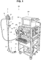
- Fig. 1 is a perspective view schematically illustrating an example of an endoscope apparatus that is configured of an endoscope according to the present embodiment and a peripheral apparatus.
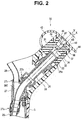
- Fig. 2 is a cross-sectional diagram illustrating a configuration of a forceps plug that is attached to a treatment instrument insertion pipe sleeve of a treatment instrument insertion port provided in an operation section.
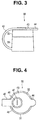
- Fig. 3 is a side view illustrating the configuration of a top view of the forceps plug in a state in which a lid-like member engages with a barrel-like member.
- Fig. 4 is a top view illustrating the configuration of the forceps plug in the state in which the lid-like member engages with the barrel-like member.
- Fig. 1 is a perspective view schematically illustrating an example of an endoscope apparatus that is configured of an endoscope according to the present embodiment and a peripheral apparatus.
- Fig. 2 is a cross-sectional diagram illustrating a configuration of a forceps plug that is
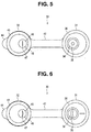
- FIG. 5 is a top view illustrating the configuration of the forceps plug in a state in which the lid-like member is released from the barrel-like member.
- Fig. 6 is a top view illustrating a configuration of a forceps plug in a state in which a lid-like member is released from a barrel-like member according to a first modification.
- Fig. 7 is a top view illustrating a configuration of a forceps plug in a state in which a lid-like member engages with a barrel-like member according to a second modification.
- Fig. 8 is a top view illustrating the configuration of the forceps plug in a state in which the lid-like member is released from the barrel-like member according to the second modification.
- FIG. 9 is a cross-sectional diagram illustrating a configuration of a forceps plug that is attached to a treatment instrument insertion pipe sleeve of a treatment instrument insertion port provided in an operation section according to a third modification.
- Fig. 10 is a cross-sectional diagram illustrating a configuration of a forceps plug that is attached to a treatment instrument insertion pipe sleeve of a treatment instrument insertion port provided in an operation section according to a forth modification.
- Fig. 11 is a cross-sectional diagram illustrating a configuration of a forceps plug that is attached to a treatment instrument insertion pipe sleeve of a treatment instrument insertion port provided in an operation section according to a fifth modification.
- Fig. 12 is a cross-sectional diagram illustrating operation of the forceps plug that is slid from the state of Fig. 11 .
- an endoscope apparatus 100 includes an endoscope 1 and a peripheral apparatus 200.
- the endoscope 1 includes, as a main part: an insertion section 2 that is inserted into a subject; an operation section 3 that is continuously provided at a proximal end in an insertion direction S of the insertion section 2 (hereinafter simply referred to as a proximal end); a universal cord 5 that is extended from the operation section 3; and a connector 6 that is provided at an extending end of the universal cord 5.
- the peripheral apparatus 200 includes a light source device 202, a video processor 203, a connection cable 204, and a monitor 205 that are mounted on a rack 201.
- the connection cable 204 electrically connects the light source device 202 with the video processor 203.
- the endoscope 1 having the above-described configuration and the peripheral apparatus 200 are connected with each other through the connector 6.
- the connector 6 is connected with, for example, the light source device 202 of the peripheral apparatus 200.
- a light guide transmits illumination light from the light source device 202 to an illumination lens of a distal end portion 11 to apply the illumination light into the subject.
- the illumination lens is described later but is not illustrated in the drawings.
- the operation section 3 of the endoscope 1 includes: a bending operation knob 21; an air/water feeding operation button 22; a suction operation button 23; and a raising base operation knob 24 that is pivotally operated to pull or relax a wire that raises or lowers a rising base.
- the wire is described later.
- the raising base is provided on the distal end portion 11 but is not illustrated in the drawings.
- the operation section 3 includes a treatment instrument insertion port 25 through which a choledochoscope, a treatment instrument, and the like are inserted into a treatment instrument insertion channel 26.
- the treatment instrument insertion channel 26 is a conduit provided inside the insertion section 2 of the endoscope 1.
- a forceps plug 30 is attached to the treatment instrument insertion port 25.
- the insertion section 2 of the endoscope 1 is configured of, in order from the distal end, the distal end portion 11, a bending portion 12, and a flexible tube portion 13.
- the bending portion 12 is provided continuously with the proximal end of the distal end portion 11, and the flexible tube portion 13 is provided continuously with the proximal end of the bending portion 12.
- the bending portion 12 is so operated to be bent in, for example, four directions of right, left, up, and down by the bending operation knob 21 provided in the operation section 3.
- the forceps plug 30 is detachably attached to a treatment instrument insertion pipe sleeve 28 that is provided at the treatment instrument insertion port 25 of the operation section 3 connected with the treatment instrument insertion channel 26.
- proximal end portion of the treatment instrument insertion channel 26 is coupled with a distal end connection port 27a of a branched tube body 27 through a connection member.
- the branched tube body 27 serves as a bent member that is a T-shaped tube (also referred to as a K-shaped branched tube) provided and fixed inside the operation section 3.
- a treatment instrument pipe sleeve connection port 27b and a suction tube connection port 27c are provided in the branched tube body 27.
- the treatment instrument insertion pipe sleeve 28 is connected with the treatment instrument pipe sleeve connection port 27b, and an end portion of a suction tube 29 is connected with the suction tube connection port 27c.
- the forceps plug 30 includes a barrel-like member 31 and a lid-like member 32 that are each formed of an elastic rubber material.
- the lid-like member 32 has a substantially disc-like shape detachable from the barrel-like member 31. Note that the forceps plug 30 is configured such that the barrel-like member 31 and the lid-like member 32 are arranged in series to each other in a state in which the lid-like member 32 is attached to the barrel-like member 31.
- the barrel-like member 31 is attached by being detachably fitted into a circumferential groove 28a that is formed on an outer circumferential surface of the treatment instrument insertion pipe sleeve 28.
- the barrel-like member 31 has an elastic projection 33 projected from an inner circumferential surface of the barrel-like member 31, and the elastic projection 33 is fitted into the circumferential groove 28a that is formed near a port of the treatment instrument insertion pipe sleeve 28.
- elastically deforming the vicinity of the elastic projection 33 of the barrel-like member 31 allows the elastic projection 33 to be fitted into or released from the circumferential groove 28a.
- the barrel-like member 31 includes a closure film 34 (see Fig. 2 and Fig. 5 ).
- the closure film 34 has a small hole 35 serving as an opening, a center of which is formed on an axis (a central axis) Y that is eccentric from a central axis X of the treatment instrument insertion pipe sleeve 28 by a predetermined distance L.
- the small hole 35 of the closure film 34 is provided at a position facing an opening end of the treatment instrument insertion pipe sleeve 28 in a state in which the barrel-like member 31 is attached to the treatment instrument insertion pipe sleeve 28.
- the small hole 35 of the closure film 34 is provided at a position that is eccentric from the center of the opening of the treatment instrument insertion pipe sleeve 28 by the predetermined distance L, in the state in which the barrel-like member 31 is attached to the treatment instrument insertion pipe sleeve 28.
- barrel-like member 31 may be preferably provided such that the small hole 35 of the closure film 34 is eccentric at a position along the inner circumferential surface of the treatment instrument insertion pipe sleeve 28.
- the choledochoscope, the treatment instrument, and the like which are not illustrated, are inserted into or removed from the treatment instrument insertion channel 26 through the treatment instrument insertion pipe sleeve 28 and the branched tube body 27 while the choledochoscope, the treatment instrument, and the like push and open the small hole 35 of the closure film 34.
- the lid-like member 32 includes a lid portion 43 that is coupled with the barrel-like member 31 through a soft coupling band portion 42.
- the soft coupling band portion 42 extends from a root part of the barrel-like member 31 (see Fig. 3 to Fig. 5 ). Further, the lid portion 43 detachably engages with a circumferential groove 37 that is provided on an outer circumferential surface of a neck part of the barrel-like member 31.
- a plug body 48 that is provided on and projected from a receiving portion 36 is fitted into the lid portion 43 in a state in which the lid portion 43 engages with the barrel-like member 31.
- the receiving portion 36 is provided at an inlet of the barrel-like member 31.
- the plug body 48 is so provided as to project toward the barrel-like member 31 in the state in which the lid portion 43 engages with the barrel-like member 31.
- releasing the lid portion 23 from the circumferential groove 37 makes it possible to draw the plug body 48 from the receiving portion 36.
- a projection 44 that is pinched when the barrel-like member 31 is released is provided on the lid portion 23 (see Fig. 4 ).
- a bottom part of the plug body 48 is configured of a closure film 46, and a slit 47 is provided at a center part of the closure film 46 (see Fig. 4 and Fig. 5 ).
- the slit 47 maintains a closed state by elasticity of the slit 47 in a normal state, and is pushed to open, by the choledochoscope, the treatment instrument, and the like that are inserted into or removed from the treatment instrument insertion channel 26.
- the slit 47 is provided such that a center part of the slit 47 faces the small hole 35 provided in the closure film 34 of the barrel-like member 31, in the state in which the lid portion 43 engages with the barrel-like member 31.
- the slit 47 of the closure film 34 is provided at a position that is eccentric from the center of the opening of the treatment instrument insertion pipe sleeve 28 by the predetermined distance L, in the state in which the barrel-like member 31 is attached to the treatment instrument insertion pipe sleeve 28 and the lid portion 43 engages with the barrel-like member 31.
- the forceps plug 30 having the above-described configuration is attached to the treatment instrument insertion pipe sleeve 28 with the predetermined shafting position such that the small hole 35 of the closure film 34 of the barrel-like member 31 and the slit 47 of the closure film 34 of the lid-like member 32 are located on an outer circumferential side in a bending direction of the branched tube body 27 and are eccentric from the center of the treatment instrument insertion pipe sleeve 28 by the predetermined distance L.
- Attaching the forceps plug 30 to the treatment instrument insertion pipe sleeve 28 with the predetermined shafting position as mentioned above makes it easy to insert an end part of a guide wire 300 (see Fig. 2 ) into the small hole 35 of the closure film 34 of the barrel-like member 31 and to easily allow the end part of the guide wire 300 to pass through the forceps plug 30 through the slit 47 of the closure film 34 of the lid-like member 32.
- the guide wire 300 that has been guided from the distal end portion 11 of the insertion section 2 into the treatment instrument insertion channel 26 in a direction opposite to the insertion direction S (see Fig. 1 ) passes through the treatment instrument insertion pipe sleeve 28 while being brought close to the outer circumferential side in the bending direction after passing through the branched tube body 27.
- the guide wire 300 that has run back through the treatment instrument insertion channel 26 to reach the treatment instrument insertion pipe sleeve 28 while being brought close to the outer circumferential side in the bending direction by the branched tube body 27, is easily inserted and guided out without being caught by the forceps plug 30.
- the endoscope 1 according to the present embodiment it is possible for the endoscope 1 according to the present embodiment to allow the guide wire 300 to easily pass through the forceps plug 30 when the guide wire 300 is installed.
- the forceps plug 30 described above may have any of configurations of various modifications described below. Note that the modifications described below may be combined in configuration.
- the small hole 35 of the closure film 34 of the barrel-like member 31 is formed in an arc shape.
- the slit 47 of the closure film 34 of the lid-like member 32 is also formed in an arc shape correspondingly.
- the small hole 35 and the slit 47 are provided such that the directions of the respective arc of the small hole 35 and the slit 47 are coincident with the circumferential direction of the treatment instrument insertion pipe sleeve 28 when the forceps plug 30 is attached to the treatment instrument insertion pipe sleeve 28 with the predetermined shafting position.
- the above-described configuration makes it possible for the guide wire 300 to easily pass through the forceps plug 30 without being caught by the forceps plug 30.
- the forceps plug 30 includes an indicator 50.
- the indicator 50 is used to determine the predetermined shafting position of the forceps plug 30 when the barrel-like member 31 and the lid-like member 32 are attached to the treatment instrument insertion pipe sleeve 28.
- the above-described configuration facilitates determination of the predetermined shafting position of the forceps plug 30 when the forceps plug 30 is attached to the treatment instrument insertion pipe sleeve 28.
- the forceps plug 30 according to the present modification has a mortar-shaped tapered surface 38 toward the closure film 34 of the barrel-like member 31.
- Such a configuration allows the guide wire 300 to easily pass through the forceps plug 30 without being caught by the forceps plug 30 because the end part of the guide wire 300 is guided to the small hole 35 by the tapered surface 38.
- the forceps plug 30 according to the present modification has a mortar-shaped tapered surface 39 toward the small hole 35, in addition to the tapered surface 38 according to the third modification.
- the tapered surface 39 is provided on a surface facing the lid portion 43 of the closure film 34 of the barrel-like member 31, namely, on a surface on side opposite to the tapered surface 38.
- Such a configuration allows the choledochoscope, the treatment instrument, and the like to easily pass through the forceps plug 30 because the respective distal ends of the choledochoscope, the treatment instrument, and the like are guided to the small hole 35 by the tapered surface 39 when the choledochoscope, the treatment instrument, and the like are inserted into the endoscope 1.
- the forceps plug 30 includes a slide mechanism portion that can change the position of the small hole 35 as an opening of the closure film 34, relative to the treatment instrument insertion pipe sleeve 28.
- the barrel-like member 31 includes: a first barrel-like member 31a provided with the small hole 35 of the closure film 34; and a second barrel-like member 31b that is detachably fitted into and attached to the treatment instrument insertion pipe sleeve 28.
- the first barrel-like member 31a is slidable with respect to the second barrel-like member 31b.
- the second barrel-like member 31b has a groove rail 31c that engages with an unillustrated projection of the first barrel-like member 31a and allows the projection to slide while preventing the first barrel-like member from being released from the second barrel-like member 31b.
- the first barrel-like member 31a is slidable, with respect to the second barrel-like member 31b, from a position at which the center axis Y of the small hole 35 of the closure film 34 is eccentric from the center axis X of the treatment instrument insertion pipe sleeve 28 by the predetermined distance L illustrated in Fig. 11 to a position at which the center axis Y of the small hole 35 of the closure film 34 is coincident with the center axis X of the treatment instrument insertion pipe sleeve 28 illustrated in Fig. 12 .
- Such a configuration causes the forceps plug 30 to be switchable between a state in which the forceps plug 30 allows the guide wire 300 to pass through the forceps plug 30 while the small hole 35 of the closure film 34 is brought close to the outer circumferential side of the treatment instrument insertion pipe sleeve 28 and a state in which the forceps plug 30 allows the choledochoscope, the treatment instrument, and the like to be inserted while the position of the small hole 35 of the closure film 34 is returned to the center of the treatment instrument insertion pipe sleeve 28.
- the configuration in which the components are removed may be extracted as the invention.
Landscapes
- Health & Medical Sciences (AREA)
- Life Sciences & Earth Sciences (AREA)
- Surgery (AREA)
- Biomedical Technology (AREA)
- Medical Informatics (AREA)
- Optics & Photonics (AREA)
- Pathology (AREA)
- Radiology & Medical Imaging (AREA)
- Biophysics (AREA)
- Engineering & Computer Science (AREA)
- Physics & Mathematics (AREA)
- Heart & Thoracic Surgery (AREA)
- Nuclear Medicine, Radiotherapy & Molecular Imaging (AREA)
- Molecular Biology (AREA)
- Animal Behavior & Ethology (AREA)
- General Health & Medical Sciences (AREA)
- Public Health (AREA)
- Veterinary Medicine (AREA)
- Endoscopes (AREA)
- Instruments For Viewing The Inside Of Hollow Bodies (AREA)
Abstract
Description
- The present invention relates to an endoscope including a treatment instrument insertion channel into which a treatment instrument is inserted.
- In recent years, observation and medical treatment have been performed on an affected part in the digestive tract system, the pancreatic and biliary duct system, and the like, with use of an insertion device, for example, a so-called side-view type endoscope (hereinafter simply referred to as an endoscope). The endoscope includes an observation optical system that is provided on a side surface of a distal end portion of an insertion section to be inserted into a subject.
- Examples of the treatment for pancreatic and biliary duct system with use of the endoscope may include, in addition to diagnosis treatment in which the biliary ducts or the pancreatic ducts are imaged by an endoscope, examination by an endoscope for the biliary tract that photographs an image inside the biliary ducts (or the pancreatic ducts) and therapeutic treatment in which gallstones in the common bile ducts are removed with use of a balloon, a gripping treatment instrument, and the like.
- In such an examination treatment, in some cases, it is necessary to insert, while a distal end of a guide wire is left inside the subject, a proximal end of the guide wire into a treatment instrument insertion channel that is provided in a contrast tube or an insertion section of the endoscope for the biliary tract, and to insert, along the guide wire, the contrast tube or the endoscope for the biliary tract into a papilla.
- When the endoscope for the biliary tract is used, the proximal end portion of the guide wire is inserted from the distal end portion of the insertion section of the endoscope for the biliary tract into a treatment instrument insertion channel provided in the endoscope, and is guided out from the treatment instrument insertion port provided in the operation section.
- For example, as disclosed in
Japanese Patent Application Laid-Open Publication No. 10-192229 - In an existing endoscope, however, the guide wire that has run back through the treatment instrument insertion channel to reach the treatment instrument insertion port may be disadvantageously caught by the forceps plug, which makes it difficult to insert the guide wire into the forceps plug.
- The present invention is made to solve the above-described difficulty, and an object of the present invention is to provide an endoscope that allows the guide wire to easily pass through the forceps plug when the guide wire is installed.
- An endoscope according to an aspect of the present invention includes: a conduit that is provided inside an insertion section and into which a guide wire is inserted in a direction opposite to an insertion direction of the insertion section; a bent conduit that is bent to make the conduit communicate with a pipe sleeve of a treatment instrument insertion port provided in an operation section; and a forceps plug that is detachable from the pipe sleeve and includes an opening through which the guide wire passes. The opening is deviated from a center of the pipe sleeve toward an outer circumferential side of a bending direction of the bent conduit.
- According to the present invention described above, it is possible to realize the endoscope that allows the guide wire to easily pass through the forceps plug when the guide wire is installed.
-
-
Fig. 1 is a perspective view schematically illustrating an example of an endoscope apparatus that is configured of an endoscope according to an embodiment of an aspect of the present invention and a peripheral apparatus; -
Fig. 2 is a cross-sectional diagram illustrating a configuration of a forceps plug that is attached to a treatment instrument insertion pipe sleeve of a treatment instrument insertion port provided in an operation section according to the embodiment of the aspect of the present invention; -
Fig. 3 is a side view illustrating the configuration of a top view of the forceps plug in a state in which a lid-like member engages with a barrel-like member, according to the embodiment of the aspect of the present invention; -
Fig. 4 is a top view illustrating the configuration of the forceps plug in the state in which the lid-like member engages with the barrel-like member, according to the embodiment of the aspect of the present invention; -
Fig. 5 is a top view illustrating the configuration of the forceps plug in a state in which the lid-like member is released from the barrel-like member, according to the embodiment of the aspect of the present invention; -
Fig. 6 is a top view illustrating a configuration of a forceps plug in a state in which a lid-like member is released from a barrel-like member, according to a first modification of the embodiment of the aspect of the present invention; -
Fig. 7 is a top view illustrating a configuration of a forceps plug in a state in which a lid-like member engages with a barrel-like member, according to a second modification of the embodiment of the aspect of the present invention; -
Fig. 8 is a top view illustrating the configuration of the forceps plug in a state in which the lid-like member is released from the barrel-like member, according to the second modification of the embodiment of the aspect of the present invention; -
Fig. 9 is a cross-sectional diagram illustrating a configuration of a forceps plug that is attached to a treatment instrument insertion pipe sleeve of a treatment instrument insertion port provided in an operation section, according to a third modification of the embodiment of the aspect of the present invention; -
Fig. 10 is a cross-sectional diagram illustrating a configuration of a forceps plug that is attached to a treatment instrument insertion pipe sleeve of a treatment instrument insertion port provided in an operation section, according to a fourth modification of the embodiment of the aspect of the present invention; -
Fig. 11 is a cross-sectional diagram illustrating a configuration of a forceps plug that is attached to a treatment instrument insertion pipe sleeve of a treatment instrument insertion port provided in an operation section, according to a fifth modification of the embodiment of the aspect of the present invention; and -
Fig. 12 is a cross-sectional diagram illustrating operation of the forceps plug that is slid from the state ofFig. 11 , according to the embodiment of the aspect of the present invention. - The present invention is described below with use of drawings.
- Note that, in the following description, the drawings based on an embodiment described below are schematically illustrated. It should be noted that relationship between a thickness and a width of each part, a ratio of thicknesses of each part, and the like are different from actual relationship, an actual ratio, and the like. A part in which the relationship and the ratio of dimensions are mutually different between drawings may be included.
- An embodiment of the present invention is described below with reference to the drawings. Note that a side-view type endoscope is described below as an example in the present embodiment.
-
Fig. 1 is a perspective view schematically illustrating an example of an endoscope apparatus that is configured of an endoscope according to the present embodiment and a peripheral apparatus.Fig. 2 is a cross-sectional diagram illustrating a configuration of a forceps plug that is attached to a treatment instrument insertion pipe sleeve of a treatment instrument insertion port provided in an operation section.Fig. 3 is a side view illustrating the configuration of a top view of the forceps plug in a state in which a lid-like member engages with a barrel-like member.Fig. 4 is a top view illustrating the configuration of the forceps plug in the state in which the lid-like member engages with the barrel-like member.Fig. 5 is a top view illustrating the configuration of the forceps plug in a state in which the lid-like member is released from the barrel-like member.Fig. 6 is a top view illustrating a configuration of a forceps plug in a state in which a lid-like member is released from a barrel-like member according to a first modification.Fig. 7 is a top view illustrating a configuration of a forceps plug in a state in which a lid-like member engages with a barrel-like member according to a second modification.Fig. 8 is a top view illustrating the configuration of the forceps plug in a state in which the lid-like member is released from the barrel-like member according to the second modification.Fig. 9 is a cross-sectional diagram illustrating a configuration of a forceps plug that is attached to a treatment instrument insertion pipe sleeve of a treatment instrument insertion port provided in an operation section according to a third modification.Fig. 10 is a cross-sectional diagram illustrating a configuration of a forceps plug that is attached to a treatment instrument insertion pipe sleeve of a treatment instrument insertion port provided in an operation section according to a forth modification.Fig. 11 is a cross-sectional diagram illustrating a configuration of a forceps plug that is attached to a treatment instrument insertion pipe sleeve of a treatment instrument insertion port provided in an operation section according to a fifth modification.Fig. 12 is a cross-sectional diagram illustrating operation of the forceps plug that is slid from the state ofFig. 11 . - As illustrated in
Fig. 1 , anendoscope apparatus 100 includes anendoscope 1 and aperipheral apparatus 200. Theendoscope 1 includes, as a main part: aninsertion section 2 that is inserted into a subject; an operation section 3 that is continuously provided at a proximal end in an insertion direction S of the insertion section 2 (hereinafter simply referred to as a proximal end); auniversal cord 5 that is extended from the operation section 3; and aconnector 6 that is provided at an extending end of theuniversal cord 5. - The
peripheral apparatus 200 includes alight source device 202, avideo processor 203, aconnection cable 204, and a monitor 205 that are mounted on arack 201. Theconnection cable 204 electrically connects thelight source device 202 with thevideo processor 203. - Further, the
endoscope 1 having the above-described configuration and theperipheral apparatus 200 are connected with each other through theconnector 6. Theconnector 6 is connected with, for example, thelight source device 202 of theperipheral apparatus 200. - A light guide transmits illumination light from the
light source device 202 to an illumination lens of adistal end portion 11 to apply the illumination light into the subject. The illumination lens is described later but is not illustrated in the drawings. - The operation section 3 of the
endoscope 1 includes: abending operation knob 21; an air/waterfeeding operation button 22; asuction operation button 23; and a raisingbase operation knob 24 that is pivotally operated to pull or relax a wire that raises or lowers a rising base. The wire is described later. The raising base is provided on thedistal end portion 11 but is not illustrated in the drawings. - Furthermore, the operation section 3 includes a treatment
instrument insertion port 25 through which a choledochoscope, a treatment instrument, and the like are inserted into a treatmentinstrument insertion channel 26. The treatmentinstrument insertion channel 26 is a conduit provided inside theinsertion section 2 of theendoscope 1. Aforceps plug 30 is attached to the treatmentinstrument insertion port 25. - The
insertion section 2 of theendoscope 1 is configured of, in order from the distal end, thedistal end portion 11, abending portion 12, and aflexible tube portion 13. Thebending portion 12 is provided continuously with the proximal end of thedistal end portion 11, and theflexible tube portion 13 is provided continuously with the proximal end of thebending portion 12. - The bending
portion 12 is so operated to be bent in, for example, four directions of right, left, up, and down by the bendingoperation knob 21 provided in the operation section 3. - As illustrated in
Fig. 2 , the forceps plug 30 is detachably attached to a treatment instrumentinsertion pipe sleeve 28 that is provided at the treatmentinstrument insertion port 25 of the operation section 3 connected with the treatmentinstrument insertion channel 26. - Note that the proximal end portion of the treatment
instrument insertion channel 26 is coupled with a distalend connection port 27a of abranched tube body 27 through a connection member. Thebranched tube body 27 serves as a bent member that is a T-shaped tube (also referred to as a K-shaped branched tube) provided and fixed inside the operation section 3. - In addition to the distal
end connection port 27a, a treatment instrument pipesleeve connection port 27b and a suctiontube connection port 27c are provided in thebranched tube body 27. - The treatment instrument
insertion pipe sleeve 28 is connected with the treatment instrument pipesleeve connection port 27b, and an end portion of asuction tube 29 is connected with the suctiontube connection port 27c. - Here, the configuration of the forceps plug 30 according to the present embodiment is described in detail below.
- As illustrated in
Fig. 2 to Fig. 5 , the forceps plug 30 includes a barrel-like member 31 and a lid-like member 32 that are each formed of an elastic rubber material. The lid-like member 32 has a substantially disc-like shape detachable from the barrel-like member 31. Note that the forceps plug 30 is configured such that the barrel-like member 31 and the lid-like member 32 are arranged in series to each other in a state in which the lid-like member 32 is attached to the barrel-like member 31. - As illustrated in
Fig. 2 , the barrel-like member 31 is attached by being detachably fitted into acircumferential groove 28a that is formed on an outer circumferential surface of the treatment instrumentinsertion pipe sleeve 28. - In other words, the barrel-
like member 31 has anelastic projection 33 projected from an inner circumferential surface of the barrel-like member 31, and theelastic projection 33 is fitted into thecircumferential groove 28a that is formed near a port of the treatment instrumentinsertion pipe sleeve 28. - Further, elastically deforming the vicinity of the
elastic projection 33 of the barrel-like member 31 allows theelastic projection 33 to be fitted into or released from thecircumferential groove 28a. - The barrel-
like member 31 includes a closure film 34 (seeFig. 2 andFig. 5 ). Theclosure film 34 has asmall hole 35 serving as an opening, a center of which is formed on an axis (a central axis) Y that is eccentric from a central axis X of the treatment instrumentinsertion pipe sleeve 28 by a predetermined distance L. - The
small hole 35 of theclosure film 34 is provided at a position facing an opening end of the treatment instrumentinsertion pipe sleeve 28 in a state in which the barrel-like member 31 is attached to the treatment instrumentinsertion pipe sleeve 28. - In other words, the
small hole 35 of theclosure film 34 is provided at a position that is eccentric from the center of the opening of the treatment instrumentinsertion pipe sleeve 28 by the predetermined distance L, in the state in which the barrel-like member 31 is attached to the treatment instrumentinsertion pipe sleeve 28. - Note that the barrel-
like member 31 may be preferably provided such that thesmall hole 35 of theclosure film 34 is eccentric at a position along the inner circumferential surface of the treatment instrumentinsertion pipe sleeve 28. - Further, the choledochoscope, the treatment instrument, and the like, which are not illustrated, are inserted into or removed from the treatment
instrument insertion channel 26 through the treatment instrumentinsertion pipe sleeve 28 and thebranched tube body 27 while the choledochoscope, the treatment instrument, and the like push and open thesmall hole 35 of theclosure film 34. - The lid-
like member 32 includes alid portion 43 that is coupled with the barrel-like member 31 through a softcoupling band portion 42. The softcoupling band portion 42 extends from a root part of the barrel-like member 31 (seeFig. 3 to Fig. 5 ). Further, thelid portion 43 detachably engages with acircumferential groove 37 that is provided on an outer circumferential surface of a neck part of the barrel-like member 31. - A
plug body 48 that is provided on and projected from a receivingportion 36 is fitted into thelid portion 43 in a state in which thelid portion 43 engages with the barrel-like member 31. The receivingportion 36 is provided at an inlet of the barrel-like member 31. - The
plug body 48 is so provided as to project toward the barrel-like member 31 in the state in which thelid portion 43 engages with the barrel-like member 31. - Note that releasing the
lid portion 23 from thecircumferential groove 37 makes it possible to draw theplug body 48 from the receivingportion 36. Moreover, aprojection 44 that is pinched when the barrel-like member 31 is released is provided on the lid portion 23 (seeFig. 4 ). - A bottom part of the
plug body 48 is configured of aclosure film 46, and aslit 47 is provided at a center part of the closure film 46 (seeFig. 4 andFig. 5 ). Theslit 47 maintains a closed state by elasticity of theslit 47 in a normal state, and is pushed to open, by the choledochoscope, the treatment instrument, and the like that are inserted into or removed from the treatmentinstrument insertion channel 26. - Note that the
slit 47 is provided such that a center part of theslit 47 faces thesmall hole 35 provided in theclosure film 34 of the barrel-like member 31, in the state in which thelid portion 43 engages with the barrel-like member 31. - In other words, as with the
small hole 35 of theclosure film 34, theslit 47 of theclosure film 34 is provided at a position that is eccentric from the center of the opening of the treatment instrumentinsertion pipe sleeve 28 by the predetermined distance L, in the state in which the barrel-like member 31 is attached to the treatment instrumentinsertion pipe sleeve 28 and thelid portion 43 engages with the barrel-like member 31. - As mentioned above, the forceps plug 30 having the above-described configuration is attached to the treatment instrument
insertion pipe sleeve 28 with the predetermined shafting position such that thesmall hole 35 of theclosure film 34 of the barrel-like member 31 and theslit 47 of theclosure film 34 of the lid-like member 32 are located on an outer circumferential side in a bending direction of thebranched tube body 27 and are eccentric from the center of the treatment instrumentinsertion pipe sleeve 28 by the predetermined distance L. - Attaching the forceps plug 30 to the treatment instrument
insertion pipe sleeve 28 with the predetermined shafting position as mentioned above makes it easy to insert an end part of a guide wire 300 (seeFig. 2 ) into thesmall hole 35 of theclosure film 34 of the barrel-like member 31 and to easily allow the end part of theguide wire 300 to pass through the forceps plug 30 through theslit 47 of theclosure film 34 of the lid-like member 32. Theguide wire 300 that has been guided from thedistal end portion 11 of theinsertion section 2 into the treatmentinstrument insertion channel 26 in a direction opposite to the insertion direction S (seeFig. 1 ) passes through the treatment instrumentinsertion pipe sleeve 28 while being brought close to the outer circumferential side in the bending direction after passing through thebranched tube body 27. - As a result, in the
endoscope 1 according to the present embodiment, theguide wire 300 that has run back through the treatmentinstrument insertion channel 26 to reach the treatment instrumentinsertion pipe sleeve 28 while being brought close to the outer circumferential side in the bending direction by thebranched tube body 27, is easily inserted and guided out without being caught by theforceps plug 30. - According to the above description, it is possible for the
endoscope 1 according to the present embodiment to allow theguide wire 300 to easily pass through the forceps plug 30 when theguide wire 300 is installed. - The forceps plug 30 described above may have any of configurations of various modifications described below. Note that the modifications described below may be combined in configuration.
- As illustrated in
Fig. 6 , in the forceps plug 30 according to the present modification, thesmall hole 35 of theclosure film 34 of the barrel-like member 31 is formed in an arc shape. Theslit 47 of theclosure film 34 of the lid-like member 32 is also formed in an arc shape correspondingly. - Note that the
small hole 35 and theslit 47 are provided such that the directions of the respective arc of thesmall hole 35 and theslit 47 are coincident with the circumferential direction of the treatment instrumentinsertion pipe sleeve 28 when theforceps plug 30 is attached to the treatment instrumentinsertion pipe sleeve 28 with the predetermined shafting position. - The above-described configuration makes it possible for the
guide wire 300 to easily pass through the forceps plug 30 without being caught by theforceps plug 30. - As illustrated in
Fig. 7 and Fig. 8 , the forceps plug 30 according to the present modification includes anindicator 50. Theindicator 50 is used to determine the predetermined shafting position of the forceps plug 30 when the barrel-like member 31 and the lid-like member 32 are attached to the treatment instrumentinsertion pipe sleeve 28. - The above-described configuration facilitates determination of the predetermined shafting position of the forceps plug 30 when the
forceps plug 30 is attached to the treatment instrumentinsertion pipe sleeve 28. - The forceps plug 30 according to the present modification has a mortar-shaped tapered
surface 38 toward theclosure film 34 of the barrel-like member 31. - Such a configuration allows the
guide wire 300 to easily pass through the forceps plug 30 without being caught by the forceps plug 30 because the end part of theguide wire 300 is guided to thesmall hole 35 by the taperedsurface 38. - The forceps plug 30 according to the present modification has a mortar-shaped tapered
surface 39 toward thesmall hole 35, in addition to the taperedsurface 38 according to the third modification. The taperedsurface 39 is provided on a surface facing thelid portion 43 of theclosure film 34 of the barrel-like member 31, namely, on a surface on side opposite to the taperedsurface 38. - Such a configuration allows the choledochoscope, the treatment instrument, and the like to easily pass through the forceps plug 30 because the respective distal ends of the choledochoscope, the treatment instrument, and the like are guided to the
small hole 35 by the taperedsurface 39 when the choledochoscope, the treatment instrument, and the like are inserted into theendoscope 1. - The forceps plug 30 according to the present modification includes a slide mechanism portion that can change the position of the
small hole 35 as an opening of theclosure film 34, relative to the treatment instrumentinsertion pipe sleeve 28. - More specifically, as illustrated in
Fig. 11 and Fig. 12 , in the slide mechanism portion, the barrel-like member 31 includes: a first barrel-like member 31a provided with thesmall hole 35 of theclosure film 34; and a second barrel-like member 31b that is detachably fitted into and attached to the treatment instrumentinsertion pipe sleeve 28. The first barrel-like member 31a is slidable with respect to the second barrel-like member 31b. - Note that the second barrel-
like member 31b has agroove rail 31c that engages with an unillustrated projection of the first barrel-like member 31a and allows the projection to slide while preventing the first barrel-like member from being released from the second barrel-like member 31b. - The first barrel-
like member 31a is slidable, with respect to the second barrel-like member 31b, from a position at which the center axis Y of thesmall hole 35 of theclosure film 34 is eccentric from the center axis X of the treatment instrumentinsertion pipe sleeve 28 by the predetermined distance L illustrated inFig. 11 to a position at which the center axis Y of thesmall hole 35 of theclosure film 34 is coincident with the center axis X of the treatment instrumentinsertion pipe sleeve 28 illustrated inFig. 12 . - Such a configuration causes the forceps plug 30 to be switchable between a state in which the
forceps plug 30 allows theguide wire 300 to pass through the forceps plug 30 while thesmall hole 35 of theclosure film 34 is brought close to the outer circumferential side of the treatment instrumentinsertion pipe sleeve 28 and a state in which theforceps plug 30 allows the choledochoscope, the treatment instrument, and the like to be inserted while the position of thesmall hole 35 of theclosure film 34 is returned to the center of the treatment instrumentinsertion pipe sleeve 28. - Further, returning the position of the
small hole 35 of theclosure film 34 to the center of the treatment instrumentinsertion pipe sleeve 28 makes it possible for the forceps plug 30 to have the configuration that does not cause any trouble when the choledochoscope, the treatment instrument, and the like each having a large diameter are inserted. - The invention described in the above-described embodiment is not limited to the embodiment and the modifications, and is variously modified in implementation without departing from the scope of the invention. Further, the above-described embodiment includes inventions in various stages, and various inventions may be extracted from appropriate combination of the plurality of disclosed components.
- For example, when the problems to be solved by the invention are solved and the effects described in the advantageous effects of the invention are obtainable even if some components are removed from the all components described in the embodiment, the configuration in which the components are removed may be extracted as the invention.
- The present application is based upon and claims the benefit of priority of
Japanese Patent Application No. 2014-263189
Claims (8)
- An endoscope, comprising:a conduit that is provided inside an insertion section and into which a guide wire is inserted in a direction opposite to an insertion direction of the insertion section;a bent conduit that is bent to make the conduit communicate with a pipe sleeve of a treatment instrument insertion port, the treatment instrument insertion port being provided in an operation section; anda forceps plug that is detachable from the pipe sleeve and includes an opening through which the guide wire passes, whereinthe opening is deviated from a center of the pipe sleeve toward an outer circumferential side of a bending direction of the bent conduit.
- The endoscope according to claim 1, wherein the forceps plug is made of a member having elasticity.
- The endoscope according to claim 1 or 2, wherein the opening is provided at a position along an inner circumferential surface of the conduit.
- The endoscope according to any one of claims 1 to 3, wherein the opening has an arc shape that is coincident with a circumferential direction of the conduit.
- The endoscope according to any one of claims 1 to 4, wherein the forceps plug has an indicator that is used to determine a shafting attachment position to the pipe sleeve.
- The endoscope according to any one of claims 1 to 5, wherein a mortar-shaped tapered surface is provided around the opening that faces the conduit.
- The endoscope according to claim 6, wherein a mortar-shaped tapered surface is provided around the opening on a side opposite to the surface provided with the tapered surface.
- The endoscope according to any one of claims 1 to 7, wherein the forceps plug includes a mechanism portion slidable from a position at which the opening is deviated from the center of the pipe sleeve toward the outer circumferential side of the bending direction of the bent conduit to a position at which a center of the opening is coincident with the center of the pipe sleeve.
Applications Claiming Priority (2)
| Application Number | Priority Date | Filing Date | Title |
|---|---|---|---|
| JP2014263189 | 2014-12-25 | ||
| PCT/JP2015/074963 WO2016103794A1 (en) | 2014-12-25 | 2015-09-02 | Endoscope |
Publications (2)
| Publication Number | Publication Date |
|---|---|
| EP3184023A1 true EP3184023A1 (en) | 2017-06-28 |
| EP3184023A4 EP3184023A4 (en) | 2018-07-18 |
Family
ID=56149836
Family Applications (1)
| Application Number | Title | Priority Date | Filing Date |
|---|---|---|---|
| EP15872363.5A Withdrawn EP3184023A4 (en) | 2014-12-25 | 2015-09-02 | Endoscope |
Country Status (5)
| Country | Link |
|---|---|
| US (1) | US10478046B2 (en) |
| EP (1) | EP3184023A4 (en) |
| JP (1) | JP6049950B2 (en) |
| CN (1) | CN106793919B (en) |
| WO (1) | WO2016103794A1 (en) |
Cited By (1)
| Publication number | Priority date | Publication date | Assignee | Title |
|---|---|---|---|---|
| EP4238477A1 (en) * | 2022-03-04 | 2023-09-06 | Ambu A/S | Endoscope comprising a biopsy valve |
Families Citing this family (3)
| Publication number | Priority date | Publication date | Assignee | Title |
|---|---|---|---|---|
| CN112822970A (en) | 2018-11-02 | 2021-05-18 | 波士顿科学有限公司 | Accessory for endoscope |
| CN114727750B (en) * | 2019-11-19 | 2025-06-10 | 豪雅株式会社 | Endoscope |
| WO2021260790A1 (en) * | 2020-06-23 | 2021-12-30 | オリンパス株式会社 | Endoscope |
Family Cites Families (19)
| Publication number | Priority date | Publication date | Assignee | Title |
|---|---|---|---|---|
| US4270525A (en) * | 1978-04-17 | 1981-06-02 | Olympus Optical Co., Ltd. | Suction control device for an endoscope |
| JPS57117820A (en) * | 1981-01-12 | 1982-07-22 | Olympus Optical Co | Forcept gasket of endoscope |
| JPS5854923A (en) * | 1981-09-25 | 1983-04-01 | オリンパス光学工業株式会社 | Endoscope |
| JP3015277B2 (en) * | 1995-05-16 | 2000-03-06 | オリンパス光学工業株式会社 | Endoscope device |
| JP3327803B2 (en) * | 1997-01-11 | 2002-09-24 | 富士写真光機株式会社 | Endoscope forceps stopper |
| US6663598B1 (en) * | 2000-05-17 | 2003-12-16 | Scimed Life Systems, Inc. | Fluid seal for endoscope |
| JP4262631B2 (en) * | 2004-01-13 | 2009-05-13 | オリンパス株式会社 | Ultrasonic treatment device |
| JP4772450B2 (en) * | 2005-10-17 | 2011-09-14 | オリンパスメディカルシステムズ株式会社 | Endoscope |
| EP1991288B1 (en) * | 2006-02-24 | 2015-01-21 | United States Endoscopy Group, Inc. | Endoscopic suction device |
| US8926506B2 (en) * | 2009-03-06 | 2015-01-06 | Ethicon Endo-Surgery, Inc. | Methods and devices for providing access into a body cavity |
| US8480570B2 (en) * | 2007-02-12 | 2013-07-09 | Boston Scientific Scimed, Inc. | Endoscope cap |
| JP5139742B2 (en) * | 2007-08-03 | 2013-02-06 | オリンパスメディカルシステムズ株式会社 | Endoscope |
| US20100087710A1 (en) * | 2008-05-19 | 2010-04-08 | Boston Scientific Scimed, Inc. | Integrated Locking Device With Fluid Control |
| US8460176B2 (en) * | 2009-04-29 | 2013-06-11 | Cook Medical Technologies Llc | Adaptor for an endoscope |
| JP5400084B2 (en) * | 2011-03-28 | 2014-01-29 | 富士フイルム株式会社 | Plug and endoscope |
| JP5602712B2 (en) * | 2011-11-21 | 2014-10-08 | 富士フイルム株式会社 | Endoscope suction line switching device |
| EP2679139B1 (en) * | 2011-12-16 | 2016-01-13 | Olympus Corporation | Resin tube |
| CN103211565B (en) * | 2013-03-25 | 2014-11-05 | 常州德天医疗器械有限公司 | Multifunctional endoscope path instrument |
| EP2974646B1 (en) * | 2013-04-22 | 2017-12-06 | Olympus Corporation | Endoscope adapter and endoscope |
-
2015
- 2015-09-02 WO PCT/JP2015/074963 patent/WO2016103794A1/en not_active Ceased
- 2015-09-02 CN CN201580050500.9A patent/CN106793919B/en active Active
- 2015-09-02 JP JP2016530259A patent/JP6049950B2/en active Active
- 2015-09-02 EP EP15872363.5A patent/EP3184023A4/en not_active Withdrawn
-
2017
- 2017-03-31 US US15/475,853 patent/US10478046B2/en active Active
Cited By (2)
| Publication number | Priority date | Publication date | Assignee | Title |
|---|---|---|---|---|
| EP4238477A1 (en) * | 2022-03-04 | 2023-09-06 | Ambu A/S | Endoscope comprising a biopsy valve |
| US12440093B2 (en) | 2022-03-04 | 2025-10-14 | Ambu A/S | Endoscope comprising a biopsy valve |
Also Published As
| Publication number | Publication date |
|---|---|
| WO2016103794A1 (en) | 2016-06-30 |
| JP6049950B2 (en) | 2016-12-21 |
| JPWO2016103794A1 (en) | 2017-04-27 |
| CN106793919A (en) | 2017-05-31 |
| CN106793919B (en) | 2019-06-11 |
| US10478046B2 (en) | 2019-11-19 |
| US20170202438A1 (en) | 2017-07-20 |
| EP3184023A4 (en) | 2018-07-18 |
Similar Documents
| Publication | Publication Date | Title |
|---|---|---|
| JP6854913B2 (en) | Endoscope devices, medical devices and strips | |
| US11432709B2 (en) | Endoscope system | |
| US20120238805A1 (en) | Endoscopic device | |
| EP1769717A1 (en) | Endoscope insert part, endoscope, and endoscope system | |
| WO2019232168A1 (en) | Surgical training models, systems, and methods | |
| US10478046B2 (en) | Endoscope | |
| CN107847704B (en) | Noninvasive ventilated bronchoscopy scope guide and method | |
| CN104717914A (en) | Endocope | |
| CN107427196A (en) | endotracheal tube insertion device | |
| CN109068963B (en) | appliance insertion aids | |
| JP3209757U (en) | Laryngoscope | |
| JP2019522545A (en) | Adapter for multiple types of endoscopes | |
| JP2006280602A (en) | Endoscope | |
| CN112399815B (en) | Endoscopic auxiliary equipment and endoscope | |
| US11464403B2 (en) | Tracheal tube insertion aid kit | |
| PL410915A1 (en) | Video-endoscopic equipment with one-time use of function channels | |
| US8460248B2 (en) | Endoscopic bite guard and related methods of use | |
| US8038597B2 (en) | Instrument for endoscope | |
| JP2014239788A (en) | Capsule endoscope guiding tool | |
| JP6899316B2 (en) | Lacrimal duct endoscopy | |
| JP5415746B2 (en) | Endoscope system | |
| JP3739746B2 (en) | Endoscope stylet | |
| CN105147425A (en) | Upper digestive tract support pushing system with short sheath tube | |
| CN215937593U (en) | Multipurpose digestive endoscope working channel expansion sleeve | |
| BR202024013160U2 (en) | Flexible optical rod for exploring body cavities. |
Legal Events
| Date | Code | Title | Description |
|---|---|---|---|
| STAA | Information on the status of an ep patent application or granted ep patent |
Free format text: STATUS: THE INTERNATIONAL PUBLICATION HAS BEEN MADE |
|
| PUAI | Public reference made under article 153(3) epc to a published international application that has entered the european phase |
Free format text: ORIGINAL CODE: 0009012 |
|
| STAA | Information on the status of an ep patent application or granted ep patent |
Free format text: STATUS: REQUEST FOR EXAMINATION WAS MADE |
|
| 17P | Request for examination filed |
Effective date: 20170324 |
|
| AK | Designated contracting states |
Kind code of ref document: A1 Designated state(s): AL AT BE BG CH CY CZ DE DK EE ES FI FR GB GR HR HU IE IS IT LI LT LU LV MC MK MT NL NO PL PT RO RS SE SI SK SM TR |
|
| AX | Request for extension of the european patent |
Extension state: BA ME |
|
| DAV | Request for validation of the european patent (deleted) | ||
| DAX | Request for extension of the european patent (deleted) | ||
| A4 | Supplementary search report drawn up and despatched |
Effective date: 20180619 |
|
| RIC1 | Information provided on ipc code assigned before grant |
Ipc: A61B 1/005 20060101ALI20180613BHEP Ipc: A61B 1/018 20060101ALI20180613BHEP Ipc: A61B 1/012 20060101ALI20180613BHEP Ipc: A61B 1/01 20060101ALI20180613BHEP Ipc: A61B 1/00 20060101AFI20180613BHEP |
|
| STAA | Information on the status of an ep patent application or granted ep patent |
Free format text: STATUS: THE APPLICATION IS DEEMED TO BE WITHDRAWN |
|
| 18D | Application deemed to be withdrawn |
Effective date: 20190117 |