EP3184021A1 - Guidance device and capsule medical device guidance system - Google Patents
Guidance device and capsule medical device guidance system Download PDFInfo
- Publication number
- EP3184021A1 EP3184021A1 EP15833787.3A EP15833787A EP3184021A1 EP 3184021 A1 EP3184021 A1 EP 3184021A1 EP 15833787 A EP15833787 A EP 15833787A EP 3184021 A1 EP3184021 A1 EP 3184021A1
- Authority
- EP
- European Patent Office
- Prior art keywords
- magnetic field
- unit
- medical device
- capsule medical
- capsule endoscope
- Prior art date
- Legal status (The legal status is an assumption and is not a legal conclusion. Google has not performed a legal analysis and makes no representation as to the accuracy of the status listed.)
- Withdrawn
Links
- 239000002775 capsule Substances 0.000 title claims abstract description 235
- 230000008859 change Effects 0.000 claims abstract description 13
- 238000010586 diagram Methods 0.000 description 37
- 230000036544 posture Effects 0.000 description 35
- 238000000034 method Methods 0.000 description 21
- 238000003384 imaging method Methods 0.000 description 20
- 230000004048 modification Effects 0.000 description 17
- 238000012986 modification Methods 0.000 description 17
- 238000001727 in vivo Methods 0.000 description 14
- 238000004891 communication Methods 0.000 description 10
- 230000008569 process Effects 0.000 description 9
- 230000005415 magnetization Effects 0.000 description 7
- 210000001035 gastrointestinal tract Anatomy 0.000 description 5
- 238000005286 illumination Methods 0.000 description 5
- 230000003287 optical effect Effects 0.000 description 5
- 210000000056 organ Anatomy 0.000 description 5
- 239000003990 capacitor Substances 0.000 description 4
- 239000007788 liquid Substances 0.000 description 4
- 239000003550 marker Substances 0.000 description 4
- 230000007246 mechanism Effects 0.000 description 4
- 238000001514 detection method Methods 0.000 description 3
- 210000002784 stomach Anatomy 0.000 description 3
- 239000003795 chemical substances by application Substances 0.000 description 2
- 239000000284 extract Substances 0.000 description 2
- 230000006870 function Effects 0.000 description 2
- 238000009434 installation Methods 0.000 description 2
- 230000003321 amplification Effects 0.000 description 1
- 210000000436 anus Anatomy 0.000 description 1
- 238000006243 chemical reaction Methods 0.000 description 1
- 239000003086 colorant Substances 0.000 description 1
- 230000000694 effects Effects 0.000 description 1
- 230000005684 electric field Effects 0.000 description 1
- 210000003238 esophagus Anatomy 0.000 description 1
- 230000037406 food intake Effects 0.000 description 1
- 230000005484 gravity Effects 0.000 description 1
- 230000000968 intestinal effect Effects 0.000 description 1
- 239000004973 liquid crystal related substance Substances 0.000 description 1
- 238000003199 nucleic acid amplification method Methods 0.000 description 1
- 230000002572 peristaltic effect Effects 0.000 description 1
- 230000004044 response Effects 0.000 description 1
- 238000007493 shaping process Methods 0.000 description 1
- 239000000725 suspension Substances 0.000 description 1
- XLYOFNOQVPJJNP-UHFFFAOYSA-N water Substances O XLYOFNOQVPJJNP-UHFFFAOYSA-N 0.000 description 1
Images





Classifications
-
- A—HUMAN NECESSITIES
- A61—MEDICAL OR VETERINARY SCIENCE; HYGIENE
- A61B—DIAGNOSIS; SURGERY; IDENTIFICATION
- A61B1/00—Instruments for performing medical examinations of the interior of cavities or tubes of the body by visual or photographical inspection, e.g. endoscopes; Illuminating arrangements therefor
- A61B1/04—Instruments for performing medical examinations of the interior of cavities or tubes of the body by visual or photographical inspection, e.g. endoscopes; Illuminating arrangements therefor combined with photographic or television appliances
- A61B1/041—Capsule endoscopes for imaging
-
- A—HUMAN NECESSITIES
- A61—MEDICAL OR VETERINARY SCIENCE; HYGIENE
- A61B—DIAGNOSIS; SURGERY; IDENTIFICATION
- A61B1/00—Instruments for performing medical examinations of the interior of cavities or tubes of the body by visual or photographical inspection, e.g. endoscopes; Illuminating arrangements therefor
-
- A—HUMAN NECESSITIES
- A61—MEDICAL OR VETERINARY SCIENCE; HYGIENE
- A61B—DIAGNOSIS; SURGERY; IDENTIFICATION
- A61B1/00—Instruments for performing medical examinations of the interior of cavities or tubes of the body by visual or photographical inspection, e.g. endoscopes; Illuminating arrangements therefor
- A61B1/00147—Holding or positioning arrangements
- A61B1/00158—Holding or positioning arrangements using magnetic field
-
- A—HUMAN NECESSITIES
- A61—MEDICAL OR VETERINARY SCIENCE; HYGIENE
- A61B—DIAGNOSIS; SURGERY; IDENTIFICATION
- A61B5/00—Measuring for diagnostic purposes; Identification of persons
- A61B5/0059—Measuring for diagnostic purposes; Identification of persons using light, e.g. diagnosis by transillumination, diascopy, fluorescence
- A61B5/0082—Measuring for diagnostic purposes; Identification of persons using light, e.g. diagnosis by transillumination, diascopy, fluorescence adapted for particular medical purposes
- A61B5/0084—Measuring for diagnostic purposes; Identification of persons using light, e.g. diagnosis by transillumination, diascopy, fluorescence adapted for particular medical purposes for introduction into the body, e.g. by catheters
-
- A—HUMAN NECESSITIES
- A61—MEDICAL OR VETERINARY SCIENCE; HYGIENE
- A61B—DIAGNOSIS; SURGERY; IDENTIFICATION
- A61B5/00—Measuring for diagnostic purposes; Identification of persons
- A61B5/06—Devices, other than using radiation, for detecting or locating foreign bodies ; Determining position of diagnostic devices within or on the body of the patient
- A61B5/061—Determining position of a probe within the body employing means separate from the probe, e.g. sensing internal probe position employing impedance electrodes on the surface of the body
- A61B5/062—Determining position of a probe within the body employing means separate from the probe, e.g. sensing internal probe position employing impedance electrodes on the surface of the body using magnetic field
-
- A—HUMAN NECESSITIES
- A61—MEDICAL OR VETERINARY SCIENCE; HYGIENE
- A61B—DIAGNOSIS; SURGERY; IDENTIFICATION
- A61B5/00—Measuring for diagnostic purposes; Identification of persons
- A61B5/68—Arrangements of detecting, measuring or recording means, e.g. sensors, in relation to patient
- A61B5/6846—Arrangements of detecting, measuring or recording means, e.g. sensors, in relation to patient specially adapted to be brought in contact with an internal body part, i.e. invasive
- A61B5/6847—Arrangements of detecting, measuring or recording means, e.g. sensors, in relation to patient specially adapted to be brought in contact with an internal body part, i.e. invasive mounted on an invasive device
- A61B5/6861—Capsules, e.g. for swallowing or implanting
-
- A—HUMAN NECESSITIES
- A61—MEDICAL OR VETERINARY SCIENCE; HYGIENE
- A61B—DIAGNOSIS; SURGERY; IDENTIFICATION
- A61B2560/00—Constructional details of operational features of apparatus; Accessories for medical measuring apparatus
- A61B2560/02—Operational features
- A61B2560/0204—Operational features of power management
- A61B2560/0214—Operational features of power management of power generation or supply
- A61B2560/0219—Operational features of power management of power generation or supply of externally powered implanted units
-
- A—HUMAN NECESSITIES
- A61—MEDICAL OR VETERINARY SCIENCE; HYGIENE
- A61B—DIAGNOSIS; SURGERY; IDENTIFICATION
- A61B5/00—Measuring for diagnostic purposes; Identification of persons
- A61B5/145—Measuring characteristics of blood in vivo, e.g. gas concentration or pH-value ; Measuring characteristics of body fluids or tissues, e.g. interstitial fluid or cerebral tissue
- A61B5/14539—Measuring characteristics of blood in vivo, e.g. gas concentration or pH-value ; Measuring characteristics of body fluids or tissues, e.g. interstitial fluid or cerebral tissue for measuring pH
Definitions
- the present invention relates to a guiding device and a capsule medical device guiding system for guiding a capsule medical device introduced into a subject.
- a capsule medical device has been developed that is configured to be introduced into a subject to obtain various kinds of information about the inside of the subject, or to administer a medical agent or the like into the subject.
- a capsule endoscope formed to have such a size as to allow itself to be introduced into a digestive tract of a subject is known.
- the capsule endoscope includes an imaging function and a wireless communication function inside a capsule-shaped casing.
- the capsule endoscope is swallowed by a subject and performs imaging while moving through the inside of a digestive tract by means of peristaltic movement or the like.
- the capsule endoscope then sequentially and wirelessly transmits image data of images of the inside of an organ of the subject (hereinafter also referred to as an in-vivo image).
- the wirelessly transmitted image data are received by a receiving device provided outside the subject and obtained by an image display device such as a workstation to be subjected to a predetermined image process. Consequently, the in-vivo image of the subject can be displayed on a screen of the image display device in the form of a still image or a motion image.
- the guiding device guides, by means of a magnetic field, a capsule endoscope introduced into a subject.
- a permanent magnet is provided inside the capsule endoscope, and a magnetic field generation unit such as an electromagnet and a permanent magnet is provided in the guiding device.
- a liquid such as water is then introduced into a digestive tract of the subject such as a stomach, and the capsule endoscope is caused to float in the liquid.
- the capsule endoscope inside the subject is guided by a magnetic field generated by the magnetic field generation unit.
- the guiding system is provided with a display unit that receives image data obtained by the capsule endoscope and displays an in-vivo image. This allows a user to operate the guidance for the capsule endoscope using an operation input unit provided on the guiding device with reference to the in-vivo image displayed on the display unit.
- Patent Literature 1 Japanese Translation of PCT International Application Publication No. JP-T-2008-503310 Summary
- a magnetic field generating unit In a system that guides a capsule medical device by means of a magnetic field, generally, a magnetic field generating unit generates a magnetic field that generates, for a capsule medical device located on an arbitrary plane, magnetic attractive force in such a direction as to restrain the capsule medical device to a specific position.
- a single permanent magnet or electromagnet is used as the magnetic field generating unit that generates the magnetic field having such a property.
- the magnetic field generated by the magnetic field generating unit is changed, whereby the position to which the capsule medical device is restrained is moved, and the capsule medical device is guided on the arbitrary plane.
- the position to which the capsule medical device is restrained by the magnetic attractive force is referred to as a restrained position.
- this phenomenon can be generated when a position of the single permanent magnet or electromagnet is moved.
- a similar phenomenon can be generated in such a manner that current that flows into each electromagnet is adjusted in a unit including a plurality of electromagnets, or a relative positional relation between permanent magnets is changed in a unit including a plurality of permanent magnets.
- the present invention has been made in view of the foregoing, and an object of the invention is to provide a guiding device and a capsule medical device guiding system that are capable of guiding a capsule medical device without leaving the capsule medical device located off an original restrained position within a subject.
- a guiding device configured to introduce a capsule medical device in which a magnet is disposed into a subject, and configured to guide the capsule medical device within the subject by means of a magnetic field.
- the guiding device includes: a magnetic field generating unit configured to generate the magnetic field to be applied to the magnet disposed in the capsule medical device to guide the capsule medical device; a position detecting unit configured to detect a position of the capsule medical device in the subject to output positional information; and a control unit configured to control the magnetic field generating unit to change distribution of the magnetic field relative to the capsule medical device.
- the magnetic field generating unit is configured to generate the magnetic field for creating magnetic attractive force in such a direction as to restrain the capsule medical device at a specific position on an arbitrary horizontal plane.
- the control unit is configured to change the distribution of the magnetic field relative to the capsule medical device when a distance between the specific position and the capsule medical device becomes greater than a threshold value.
- the above-described guiding device further includes an operation input unit configured to input instruction information for guiding the capsule medical device, into the control unit in accordance with external operation.
- the control unit is configured to switch between a first control mode and a second control mode in accordance with the distance, the first control mode causing the magnetic field generating unit to generate the magnetic field that brings the specific position relatively close to the capsule medical device, and the second control mode causing the magnetic field generating unit to generate the magnetic field that guides the capsule medical device based on the instruction information.
- control unit is configured to: execute the second control mode when the distance is equal to or less than the threshold value; and switch from the second control mode to the first control mode when the distance becomes greater than the threshold value.
- control unit is configured to switch from the first control mode to the second control mode when the distance becomes less than a second threshold value that is smaller than the threshold value.
- control unit is configured to: execute the second control mode when the distance is equal to or less than the threshold value; and maintain the second control mode when the distance becomes greater than the threshold value while the operation input unit is operated.
- the above-described guiding device further includes a display unit configured to display information under control of the control unit. While the distance is greater than the threshold value and the second control mode is maintained, the control unit is configured to cause the display unit to display a sign indicating that the distance is greater than the threshold value.
- the display unit is configured to: display, based on the instruction information, a sign indicating a direction in which the capsule medical device is guidable; and change a display mode of the sign depending on which control mode the control unit executes.
- the magnetic field generating unit includes: a permanent magnet configured to generate the magnetic field; and a drive unit configured to change a relative position of the permanent magnet to the capsule medical device.
- the control unit is configured to cause the drive unit to change the relative position and thereby to move the specific position while executing the first control mode.
- the magnetic field generating unit includes a plurality of electromagnets.
- the control unit is configured to move the specific position under a synthetic magnetic field formed by magnetic fields generated by the plurality of electromagnets while executing the first control mode.
- a capsule medical device guiding system includes the guiding device and the capsule medical device.
- the present invention since distribution of a magnetic field relative to a capsule medical device is changed when a distance between a specific position, which is an original restrained position of the capsule medical device in the magnetic field generated by a magnetic field generating unit, and a current position of the capsule medical device becomes greater than a threshold value, it is possible to guide the capsule medical device without leaving the capsule medical device located off the restrained position.
- a guiding device and a capsule medical device guiding system according to some embodiments of the present invention will be described with reference to the drawings.
- a capsule endoscope that is orally introduced into a subject to capture the inside of a digestive tract of the subject is described as an example of a capsule medical device to be guided by the capsule medical device guiding system according to the present embodiment.
- the present invention is not limited by this embodiment.
- the present invention can be applied to guidance for various capsule-shaped medical devices such as, for example, a capsule endoscope that moves through the inside of a lumen ranging from an esophagus to an anus of a subject, a capsule medical device that delivers a medical agent or the like into a subject, and a capsule medical device including a pH sensor that measures pH within a subject.
- a capsule endoscope that moves through the inside of a lumen ranging from an esophagus to an anus of a subject
- a capsule medical device that delivers a medical agent or the like into a subject
- a capsule medical device including a pH sensor that measures pH within a subject.
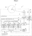
- FIG. 1 is a diagram illustrating an exemplary configuration of a capsule medical device guiding system according to an embodiment of the present invention.
- the capsule medical device guiding system 1 includes a capsule endoscope 10 and a guiding device 20.
- the capsule endoscope 10 is a capsule medical device that is introduced into a body cavity of a subject, and a permanent magnet is provided inside the capsule endoscope 10.
- the guiding device 20 generates a magnetic field MG and guides the capsule endoscope 10 introduced into a subject.
- the capsule endoscope 10 is introduced into an organ of a subject together with a predetermined liquid by means of oral ingestion or the like, moves through the inside of a digestive tract, and is eventually discharged to the outside of the subject. During this time, the capsule endoscope 10 floats in the liquid introduced into the organ of the subject such as a stomach, and sequentially captures in-vivo images while being guided by the magnetic field MG. The capsule endoscope 10 then sequentially and wirelessly transmits image data corresponding to the in-vivo images obtained by the imaging.
- FIG. 2 is a schematic diagram illustrating an exemplary internal structure of the capsule endoscope 10.
- the capsule endoscope 10 includes a capsule-shaped casing 100, an imaging unit 11, a control unit 15, a wireless communication unit 16, a power supply unit 17, a permanent magnet 18, and a position detecting magnetic field generation unit 19.
- the capsule-shaped casing 100 is an exterior formed to have such a size as to allow itself to be easily introduced into an organ of a subject.
- the imaging unit 11 outputs an image signal of the inside of a subject that has been captured.
- the control unit 15 processes the image signal output from the imaging unit 11 and controls each element of the capsule endoscope 10.
- the wireless communication unit 16 wirelessly transmits the image signal processed by the control unit 15 to the outside of the capsule endoscope 10.
- the power supply unit 17 supplies power to each element of the capsule endoscope 10.
- the permanent magnet 18 enables the guiding device 20 to perform guidance.
- the position detecting magnetic field generation unit 19 generates a position detecting magnetic field that is a magnetic field used for detecting a position of the capsule endoscope 10.
- the capsule-shaped casing 100 is an outer casing formed to have such a size as to allow itself to be introduced into an organ of a subject.
- the capsule-shaped casing 100 has a tubular casing 101 and dome-shaped casings 102 and 103, and is configured such that both opening ends of the tubular casing 101 are closed by the dome-shaped casings 102 and 103.
- Each of the tubular casing 101 and the dome-shaped casing 103 is a colored casing that is substantially opaque to visible light.
- the dome-shaped casing 102 is a dome-like optical member that is transparent to light having a predetermined wavelength band such as visible light. As illustrated in FIG. 2 , this capsule-shaped casing 100 liquid-tightly contains the imaging unit 11, the control unit 15, the wireless communication unit 16, the power supply unit 17, the permanent magnet 18, and the position detecting magnetic field generation unit 19.
- the imaging unit 11 has an illumination unit 12 such as an LED, an optical system 13 such as a condenser lens, and an image sensor 14 such as a CMOS image sensor or a CCD.
- the illumination unit 12 emits illumination light such as white light to an imaging field of the image sensor 14 to irradiate a subject within the imaging field through the dome-shaped casing 102.
- the optical system 13 collects reflected light from the imaging field onto an imaging surface of the image sensor 14 to form an image.
- the image sensor 14 converts the reflected light from the imaging field received on the imaging surface, into an electrical signal, and outputs the electrical signal as an image signal.
- the control unit 15 controls operation of the imaging unit 11 and operation of the wireless communication unit 16 and controls input and output of a signal between these elements. More specifically, the control unit 15 causes the image sensor 14 to capture a subject within the imaging field illuminated with the illumination unit 12, and performs a predetermined signal process on an image signal output from the image sensor 14. The control unit 15 further causes the wireless communication unit 16 to sequentially and wirelessly transmit the above-mentioned image signals subjected to the signal process in time series.
- the wireless communication unit 16 obtains, from the control unit 15, an image signal of an in-vivo image output from the imaging unit 11, and performs a modulation process or the like on the image signal to generate a wireless signal.
- the wireless communication unit 16 includes an antenna 16a for transmitting a wireless signal, and wirelessly transmits the generated wireless signal via the antenna 16a.
- the power supply unit 17 is a power storage unit such as a button type battery and a capacitor, and has a switch unit such as a magnetic switch or an optical switch. If the power supply unit 17 has the magnetic switch, the power supply unit 17 switches power supply on and off by a magnetic field applied from the outside. In the on state, power in the power storage unit is appropriately supplied to each element of the capsule endoscope 10, that is, the imaging unit 11, the control unit 15, and the wireless communication unit 16. In the off state, the power supply unit 17 stops supplying power to each element of the capsule endoscope 10.
- the permanent magnet 18 enables the magnetic field MG to guide the capsule endoscope 10.
- the magnetic field MG is generated by a magnetic field generating unit 25 which will be described later.
- the permanent magnet 18 is arranged to be fixed within the capsule-shaped casing 100 so that a magnetization direction Ym is inclined to a long axis La.
- the permanent magnet 18 is arranged so that the magnetization direction Ym is orthogonal to the long axis La.
- the permanent magnet 18 operates in accordance with a magnetic field applied from the outside. As a result, guidance for the capsule endoscope 10 by the magnetic field generating unit 25 is realized.
- the position detecting magnetic field generation unit 19 serves as a part of a resonance circuit and includes a marker coil 19a and a capacitor 19b.
- the marker coil 19a generates a magnetic field by means of current flow.
- the capacitor 19b forms the resonance circuit in cooperation with the marker coil 19a.
- the position detecting magnetic field generation unit 19 receives the power supply from the power supply unit 17 to generate a position detecting magnetic field having a predetermined frequency.
- the guiding device 20 includes a receiving unit 21, a position and posture detecting unit 22, a display unit 23, an operation input unit 24, the magnetic field generating unit 25, a control unit 26, and a storage unit 27.
- the receiving unit 21 wirelessly communicates with the capsule endoscope 10 to receive a wireless signal including an image signal transmitted from the capsule endoscope 10.
- the position and posture detecting unit 22 detects a position and a posture of the capsule endoscope 10 within a subject based on a position detecting magnetic field generated by the position detecting magnetic field generation unit 19 of the capsule endoscope 10.
- the display unit 23 obtains an image signal from the wireless signal received by the receiving unit 21, performs a predetermined signal process on the image signal to display an in-vivo image, and displays information such as the position and the posture of the capsule endoscope 10 within the subject.
- the operation input unit 24 accepts input of information or the like including an instruction for various types of operation in the capsule medical device guiding system 1.
- the magnetic field generating unit 25 generates a magnetic field for guiding the capsule endoscope 10.
- the control unit 26 controls each of these elements.
- the storage unit 27 stores image data or the like of an in-vivo image.
- FIG. 3 is a perspective diagram schematically illustrating an external appearance of the guiding device 20.
- the guiding device 20 is provided with a bed 20a as a table on which a subject is placed.
- the magnetic field generating unit 25 generates the magnetic field MG.
- the plurality of sensing coils 22a detects a position detecting magnetic field generated by the position detecting magnetic field generation unit 19.
- the receiving unit 21 includes a plurality of receiving antennas 21a and sequentially receives wireless signals from the capsule endoscope 10 via these receiving antennas 21a.
- the receiving unit 21 selects an antenna having the highest reception electric field strength from among these receiving antennas 21a, and performs a demodulation process or the like on a wireless signal from the capsule endoscope 10 received via the selected antenna.
- the receiving unit 21 thus extracts an image signal from the wireless signal and outputs the image signal to the display unit 23.
- the plurality of sensing coils 22a is arranged on a planar panel arranged in parallel with an upper surface of the bed 20a.
- Each of the sensing coils 22a for example, is a cylindrical coil formed in a coil spring shape, and receives a magnetic field generated by the position detecting magnetic field generation unit 19 of the capsule endoscope 10 to output a detection signal.
- the position and posture detecting unit 22 obtains a plurality of detection signals output from the respective plurality of sensing coils 22a, and performs, on these detection signals, signal processes such as waveform shaping, amplification, A/D conversion, and FFT.
- the position and posture detecting unit 22 thus extracts magnetic field information such as amplitude and a phase of a position detecting magnetic field.
- the position and posture detecting unit 22 further calculates the position and the posture of the capsule endoscope 10 based on this magnetic field information, and outputs the position and the posture of the capsule endoscope 10 as positional information.
- a method for detecting the position and the posture of the capsule endoscope 10 is not limited to the above-mentioned method using the position detecting magnetic field.
- the position and the posture of the capsule endoscope 10 may be detected based on strength distribution of a wireless signal received by the receiving unit 21.
- the position of the capsule endoscope 10 can be obtained in such a manner that an initial value of the position of the capsule endoscope 10 is appropriately set, and a process of calculating an estimate value of the position by means of the Gauss-Newton method is repeated until a shift amount between the calculated estimate value and a previous estimate value becomes equal to or less than a predetermined value.
- the display unit 23 has a screen including various displays such as a liquid crystal display.
- the display unit 23 displays, on the screen, an in-vivo image that is based on an image signal input from the receiving unit 21, positional information of the capsule endoscope 10, and various other types of information.
- the operation input unit 24 inputs operation input information into the control unit 26 in accordance with external operation by a user.
- the operation input information is instruction information for controlling the position or the posture of the capsule endoscope 10.
- the operation input unit 24 includes, for example, a joystick, a console including various buttons and various switches, and an input device such as a keyboard.
- the operation input information specifically includes information about translation operation, tilt angle changing operation, and azimuth angle changing operation or the like.
- the translation operation translates the capsule endoscope 10 in a horizontal direction or a vertical direction.
- the tilt angle changing operation changes a tilt angle of the long axis La of the capsule endoscope 10 with respect to the vertical direction.
- the azimuth angle changing operation changes an azimuth angle of the field of the imaging unit 11 provided in the capsule endoscope 10, that is, an angle around an axis in the vertical direction.
- the magnetic field generating unit 25 generates the magnetic field MG for changing, relative to a subject, the position, the tilt angle, and the azimuth angle of the capsule endoscope 10 introduced into the subject.
- the magnetic field generating unit 25 has an extracorporeal permanent magnet 25a, an in-plane position changing unit 25b, a vertical position changing unit 25c, an elevation angle changing unit 25d, and a turning angle changing unit 25e.
- the extracorporeal permanent magnet 25a generates the magnetic field MG.
- the in-plane position changing unit 25b, the vertical position changing unit 25c, the elevation angle changing unit 25d, and the turning angle changing unit 25e change the position and the posture of the extracorporeal permanent magnet 25a.
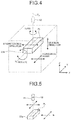
- FIG. 4 is a schematic diagram for explaining an installation state of the extracorporeal permanent magnet 25a.
- the extracorporeal permanent magnet 25a includes a bar magnet having a rectangular parallelepiped shape.
- the extracorporeal permanent magnet 25a is arranged so that one of four surfaces parallel to a magnetization direction of the extracorporeal permanent magnet 25a is parallel to a horizontal plane (XY plane) that is a plane orthogonal to a gravity direction.
- XY plane horizontal plane
- the arrangement of the extracorporeal permanent magnet 25a in the initial state of the extracorporeal permanent magnet 25a is referred to as reference arrangement.
- One of the four surfaces parallel to the magnetization direction of the extracorporeal permanent magnet 25a which faces the capsule endoscope 10 is also referred to as a capsule facing surface PL.
- the in-plane position changing unit 25b translates the extracorporeal permanent magnet 25a on the horizontal plane. Specifically, the extracorporeal permanent magnet 25a moves on the horizontal plane while a relative position between two magnetic poles magnetized in the extracorporeal permanent magnet 25a is secured.
- the vertical position changing unit 25c is a translation mechanism that translates the extracorporeal permanent magnet 25a along the vertical direction (Z direction). Specifically, the extracorporeal permanent magnet 25a moves along the vertical direction while the relative position between the two magnetic poles magnetized in the extracorporeal permanent magnet 25a is secured.
- the elevation angle changing unit 25d is a rotation mechanism that rotates the extracorporeal permanent magnet 25a on a vertical plane including the magnetization direction of the extracorporeal permanent magnet 25a to change an angle of the magnetization direction with respect to the horizontal plane.
- the elevation angle changing unit 25d rotates the extracorporeal permanent magnet 25a around an axis Y C in a Y direction.
- the axis Y C is parallel to the capsule facing surface PL, orthogonal to the magnetization direction, and passes through the center of the extracorporeal permanent magnet 25a.
- an angle between the extracorporeal permanent magnet 25a and the horizontal plane is referred to as an elevation angle.
- the turning angle changing unit 25e rotates the extracorporeal permanent magnet 25a around a vertical axis Z m passing through the center of the extracorporeal permanent magnet 25a.
- a rotational motion of the extracorporeal permanent magnet 25a around the vertical axis Z m is referred to as a turning motion.
- An angle of the turned extracorporeal permanent magnet 25a with respect to the reference arrangement is referred to as a turning angle.
- the control unit 26 controls operation of each element of the magnetic field generating unit 25 based on positional information of the capsule endoscope 10 input from the position and posture detecting unit 22 and operation input information input from the operation input unit 24.
- the control unit 26 thus changes a relative position between the extracorporeal permanent magnet 25a and a subject, a distance between the extracorporeal permanent magnet 25a and the capsule endoscope 10, and a rotation angle of the extracorporeal permanent magnet 25a from the reference arrangement, namely, the elevation angle and the turning angle, whereby the capsule endoscope 10 is guided.
- a control mode that is executed by the control unit 26 includes a first control mode and a second control mode.
- the capsule endoscope 10 In the first control mode, the capsule endoscope 10 is moved to an appropriate position relative to distribution of the magnetic field MG generated by the extracorporeal permanent magnet 25a based on positional information. In the second control mode, feedback control is performed based on positional information in accordance with operation input information, whereby the capsule endoscope 10 is guided to a position and a posture desired by a user.
- the storage unit 27 includes a storage medium and a writing reading device.
- the storage medium such as a flash memory or a hard disk, saves information in a rewritable manner.
- the writing reading device writes and reads information to and from the storage medium.
- the storage unit 27 stores image data of an in-vivo image group of a subject captured by the capsule endoscope 10.
- the storage unit 27 also stores information such as various programs and various parameters that is used by the control unit 26 to control each element of the guiding device 20.
- FIG. 5 is a schematic diagram for explaining a guiding method for translating the capsule endoscope 10 on the horizontal plane.
- a magnetic field is generated to create magnetic attractive force in such a direction as to restrain the capsule endoscope 10 at a specific position on the horizontal plane, and the magnetic field is applied to the permanent magnet 18 of the capsule endoscope 10.
- This specific position is hereinafter referred to as a restrained position.
- the permanent magnet 18 is attracted to the restrained position and the capsule endoscope 10 is thus restrained.
- the extracorporeal permanent magnet 25a is moved on the horizontal plane by the in-plane position changing unit 25b, whereby the capsule endoscope 10 is translated on the horizontal plane.
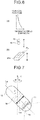
- FIG. 6 is a schematic diagram for explaining a guiding method for translating the capsule endoscope 10 in the vertical direction.
- the capsule endoscope 10 is translated in the vertical direction, as illustrated in (a) of FIG. 6 , such a magnetic field that distribution of a magnetic force gradient varies depending on a distance in a direction orthogonal to the capsule facing surface PL is applied to the permanent magnet 18 of the capsule endoscope 10. More specifically, the extracorporeal permanent magnet 25a is moved in the vertical direction by the vertical position changing unit 25c, and a distance between the extracorporeal permanent magnet 25a and the permanent magnet 18 is changed. Consequently, as illustrated in (b) of FIG. 6 , the capsule endoscope 10 is translated in the vertical direction.
- the restrained position of the capsule endoscope 10 is located on a line orthogonal to the capsule facing surface PL and passing through the center of the extracorporeal permanent magnet 25a.
- FIG. 7 is a schematic diagram for explaining a guiding method for changing the tilt angle and the azimuth angle of the capsule endoscope 10.
- the capsule endoscope 10 When the azimuth angle of the capsule endoscope 10 is changed, the capsule endoscope 10 is restrained at the restrained position, and the extracorporeal permanent magnet 25a is rotated around the vertical axis Z m passing through the center of the extracorporeal permanent magnet 25a by the turning angle changing unit 25e, whereby the turning angle is changed. As a result, the capsule endoscope 10 is rotated around a Z axis, and the azimuth angle of the capsule endoscope 10 is changed. At this time, when the elevation angle changing unit 25d and the turning angle changing unit 25e rotate the extracorporeal permanent magnet 25a, the restrained position is moved with respect to the extracorporeal permanent magnet 25a.
- control unit 26 calculates the restrained position based on the elevation angle and the turning angle of the extracorporeal permanent magnet 25a, a distance between the extracorporeal permanent magnet 25a and the horizontal plane including the position of the capsule endoscope 10, a magnetic property of the capsule endoscope 10 such as a magnetic moment, and a geometric property of the capsule endoscope 10 such as volume, mass, and a centroid position. Then, the in-plane position changing unit 25b is controlled in accordance with the elevation angle and the turning angle of the extracorporeal permanent magnet 25a so that the restrained position is not moved.
- FIG. 8 is a schematic diagram illustrating an exemplary screen displayed on the display unit 23.
- a screen M1 illustrated in FIG. 8 includes an image display area m1 and posture diagrams m2, m3.
- the posture diagrams m2, m3 indicate the posture of the capsule endoscope 10 within a subject.
- four corners of a rectangular in-vivo image are masked and displayed.
- the image display area m1 is an area on which an in-vivo image is displayed based on image signals sequentially input from the receiving unit 21.
- Operation input arrows m11 to m14 are displayed around the image display area m1.
- Each of the operation input arrows m11 to m14 serves as a sign indicating a direction of operation input for translating the capsule endoscope 10.
- the posture diagram m2 represents the posture of the capsule endoscope 10 on the horizontal plane and includes a scale m20, a model diagram m21, and operation input arrows m22, m23.
- the scale m20 indicates the azimuth angle.
- the model diagram m21 represents the posture of the capsule endoscope 10.
- Each of the operation input arrows m22, m23 serves as a sign indicating a direction of operation input for turning the capsule endoscope 10.
- the posture diagram m3 represents the posture of the capsule endoscope 10 on the vertical plane and includes a scale m30, a model diagram m31, operation input arrows m32, m33, and operation input arrows m34, m35.
- the scale m30 indicates the tilt angle.
- the model diagram m31 represents the posture of the capsule endoscope 10.
- Each of the operation input arrows m32, m33 serves as a sign indicating a direction in which operation input for translating the capsule endoscope 10 in a long axis direction is performed.
- Each of the operation input arrows m34, m35 serves as a sign indicating a direction of operation input for tilting the capsule endoscope 10.
- the operation input arrows m11 to m14, m22, m23, and m32 to m35 are set so as to be displayed in different forms in accordance with the control mode being executed by the control unit 26 and whether the capsule endoscope 10 can be guided.
- colors of the operation input arrows m11 to m14, m22, m23, and m32 to m35 are changed. For example, during a wait for operation input for the capsule endoscope 10, the operation input arrows m11 to m14, m22, m23, and m32 to m35 are displayed in white.
- the operation input arrow of a direction in which the operation input has been performed is displayed in light blue.
- the operation input arrow of a direction in which the operation input has been performed is displayed in yellow.
- the operation input arrows m11 to m14, m22, m23, and m32 to m35 are set to be not displayed.
- Operation input information input from the operation input unit 24 is reflected in a control signal that is output when the control unit 26 controls the magnetic field generating unit 25. Therefore, the postures of the model diagrams m21, m31 of the capsule endoscope 10 displayed on the posture diagrams m2, m3 can be considered to be substantially the same as the posture of the actual capsule endoscope 10 in a subject.
- FIG. 9 is a flowchart illustrating the operation of the system 1.
- FIG. 10 is a schematic diagram for explaining a guiding method for the capsule endoscope 10 in the system 1.
- the extracorporeal permanent magnet 25a and a movement on an arbitrary horizontal plane PL H of the capsule endoscope 10 guided by a magnetic field generated by the extracorporeal permanent magnet 25a are illustrated.
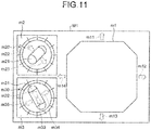
- FIGS. 11 and 12 are schematic diagrams illustrating exemplary screens displayed on the display unit 23 during the operation of the system 1.
- step S10 the control unit 26 determines whether a distance D between a restrained position P in the magnetic field generated by the magnetic field generating unit 25 and a current position of the capsule endoscope 10 on the horizontal plane PL H including the position of the capsule endoscope 10 is equal to or less than a first threshold value Th1 based on positional information output from the position and posture detecting unit 22.
- the restrained position P in the magnetic field generated by the magnetic field generating unit 25 is calculated based on the elevation angle and the turning angle of the extracorporeal permanent magnet 25a, the distance between the extracorporeal permanent magnet 25a and the horizontal plane PL H including the position of the capsule endoscope 10, the magnetic property of the capsule endoscope 10, namely, the magnetic moment, and the geometric property of the capsule endoscope 10, namely, the volume, the mass, and the centroid position.
- the threshold value Th1 is set in advance as a limit distance of a range in which the capsule endoscope 10 can be guided by the magnetic field generated by the magnetic field generating unit 25.
- step S10 No
- the control unit 26 switches to the first control mode (step S11).
- the display unit 23 stops displaying all the operation input arrows m11 to m14, m22, m23, and m32 to m35 on the screen M1 under the control of the control unit 26. This allows a user to recognize that acceptance of operation input for guiding the capsule endoscope 10 is under suspension.
- the magnetic field generating unit 25 changes the distribution of the magnetic field such that the restrained position P is brought close to the capsule endoscope 10 under the control of the control unit 26. More specifically, as illustrated in FIG. 10 , the extracorporeal permanent magnet 25a is translated on the horizontal plane PL H so that the vertical axis Z m is brought close to the capsule endoscope 10.
- the control unit 26 determines whether the distance D is equal to or less than a second threshold value Th2 based on positional information output from the position and posture detecting unit 22.
- the threshold value Th2 is set to a value less than the threshold value Th1 in advance as a limit distance by which the capsule endoscope 10 can be appropriately guided by the magnetic field generated by the magnetic field generating unit 25.
- step S14: No the operation of the system 1 proceeds to step S12.
- step S14 determines whether operation input for the operation input unit 24 for guiding the position or the posture of the capsule endoscope 10 is performed (step S15).
- step S15 When the operation input for the operation input unit 24 for guiding the position or the posture of the capsule endoscope 10 is not performed (step S15: No), the operation of the system 1 proceeds to step S10.
- step S10 when the distance D is equal to or less than the threshold value Th1 (step S10: Yes), the control unit 26 switches to the second control mode (step S16).
- step S17 the display unit 23 displays all the operation input arrows m11 to m14, m22, m23, and m32 to m35 on the screen M1 in white under the control of the control unit 26. This allows the user to recognize that the operation input for the operation input unit 24 for guiding the capsule endoscope 10 is enabled. After that, the operation of the system 1 proceeds to step S15.
- step S15 when the operation input for the operation input unit 24 for guiding the position or the posture of the capsule endoscope 10 is performed (step S15: Yes), the control unit 26 determines whether the distance D is equal to or less than the threshold value Th1 (step S18).
- the display unit 23 displays, under the control of the control unit 26, the operation input arrow for a direction corresponding to the operation input, e.g., the operation input arrow m35, in yellow, for example (step S19).
- a difference in color is indicated by a difference in pattern. This allows the user to recognize a possibility that the guidance for the capsule endoscope 10 intended by the user is not realized since the capsule endoscope 10 has gone out of the range in which the capsule endoscope 10 can be guided by the magnetic field.
- the color indicating the operation input arrow for the direction corresponding to the operation input is not limited to yellow as long as the color is different from that of the operation input arrow of another direction. It is preferable to display a conspicuous color so that the user can be alerted that the distance D is greater than the threshold value Th1. After that, the operation of the system 1 proceeds to step S21.
- step S18 when the distance D is equal to or less than the threshold value Th1 (step S18: Yes), the display unit 23 displays, under the control of the control unit 26, the operation input arrow for a direction corresponding to the operation input, in light blue, for example (step S20).
- the color indicating the operation input arrow for the direction corresponding to the operation input is not limited to light blue as long as the color is different from that of the operation input arrow for another direction, i.e., different from white, and the color is different from that of the operation input arrow of the direction in which the operation input is performed in step S19, i.e., different from yellow.
- the magnetic field generating unit 25 controls the magnetic field based on operation input information input from the operation input unit 24 under the control of the control unit 26. As a result, the magnetic field for controlling the position or the posture of the capsule endoscope 10 is generated in a subject.
- step S22 the control unit 26 determines whether operation input performed on the operation input unit 24 is ended. When the operation input is not ended (step S22: No), the operation of the system 1 returns to step S18.
- step S22: Yes the control unit 26 determines whether an instruction to end the guidance for the capsule endoscope 10 is input (step S23).
- the instruction to end the guidance is input in accordance with predetermined operation for the operation input unit 24.
- step S23: No the operation of the system 1 returns to step S10.
- step S23: Yes the operation of the system 1 is ended.
- the distance between the restrained position P in the magnetic field generated by the magnetic field generating unit 25 and the capsule endoscope 10 becomes greater than the threshold value Th1 set as the range in which the capsule endoscope 10 can be guided by the magnetic field, the distribution of the magnetic field is changed and the restrained position P is automatically brought close to the capsule endoscope 10. Therefore, the guidance for the capsule endoscope 10 can be appropriately performed again.
- the color of the operation input arrow is changed and displayed in accordance with a situation, such as when the capsule endoscope 10 exists in the range in which the capsule endoscope 10 can be guided by the magnetic field, or when the capsule endoscope 10 goes out of this range. Therefore, the user can easily grasp whether the capsule endoscope 10 can be guided as intended by the user.
- FIG. 13 is a diagram illustrating an exemplary configuration of a capsule medical device guiding system according to the first modification of the embodiment of the present invention.
- a capsule medical device guiding system 2 includes a guiding device 40 having a magnetic field generating unit 41 in place of the guiding device 20 illustrated in FIG. 1 .
- the magnetic field generating unit 41 further includes a second in-plane position changing unit 25f as compared with the magnetic field generating unit 25 illustrated in FIG. 1 .
- a configuration of each element other than the second in-plane position changing unit 25f in the capsule medical device guiding system 2 is similar to that of the above-mentioned embodiment.
- FIG. 14 is a schematic diagram illustrating an exemplary configuration of an external appearance of the guiding device 40 illustrated in FIG. 13 .
- the guiding device 40 is provided with a bed 40a as a table on which a subject is placed.
- the bed 40a can be translated in the horizontal direction.
- the magnetic field generating unit 41 that generates the magnetic field MG is arranged below the bed 40a.
- the second in-plane position changing unit 25f is a translation mechanism that translates the bed 40a in the horizontal direction.
- the second in-plane position changing unit 25f moves the bed 40a with a subject placed thereon, whereby a relative position of the capsule endoscope 10 to the magnetic field MG generated by the extracorporeal permanent magnet 25a is changed.
- the bed 40a is moved in step S13 illustrated in FIG. 9 , whereby the capsule endoscope 10 itself is brought close to the restrained position P.
- both the extracorporeal permanent magnet 25a and the bed 40a may be relatively moved to bring the capsule endoscope 10 and the restrained position P close to each other.
- FIG. 15 is a diagram illustrating an exemplary configuration of a capsule medical device guiding system according to the second modification of the embodiment of the present invention.
- a capsule medical device guiding system 3 includes a guiding device 50 having a magnetic field generating unit 51 in place of the guiding device 20 illustrated in FIG. 1 .
- the magnetic field generating unit 51 includes a plurality of electromagnets 51a, a power supply unit 51b, and a current controller 51c.
- the power supply unit 51b supplies power to each of the electromagnets 51a.
- the current controller 51c controls current that flows into each of the electromagnets 51a under the control of the control unit 26.
- the current controller 51c controls the magnitude of the current that is supplied to each of the electromagnets 51a, whereby a synthetic magnetic field is generated to define a restrained position.
- the synthetic magnetic field is applied to the permanent magnet 18 within the capsule endoscope 10.
- a configuration of each element other than the magnetic field generating unit 51 in the capsule medical device guiding system 3 is similar to that of the above-mentioned embodiment.
- the distribution of the magnetic field to be applied to the capsule endoscope 10 can be changed without providing a mechanical movement mechanism or the like. Therefore, a quick response can be realized.
Landscapes
- Health & Medical Sciences (AREA)
- Life Sciences & Earth Sciences (AREA)
- Surgery (AREA)
- Engineering & Computer Science (AREA)
- Physics & Mathematics (AREA)
- General Health & Medical Sciences (AREA)
- Biophysics (AREA)
- Veterinary Medicine (AREA)
- Public Health (AREA)
- Pathology (AREA)
- Biomedical Technology (AREA)
- Heart & Thoracic Surgery (AREA)
- Medical Informatics (AREA)
- Molecular Biology (AREA)
- Animal Behavior & Ethology (AREA)
- Optics & Photonics (AREA)
- Nuclear Medicine, Radiotherapy & Molecular Imaging (AREA)
- Radiology & Medical Imaging (AREA)
- Human Computer Interaction (AREA)
- Endoscopes (AREA)
Abstract
Description
- The present invention relates to a guiding device and a capsule medical device guiding system for guiding a capsule medical device introduced into a subject. Background
- Conventionally, a capsule medical device has been developed that is configured to be introduced into a subject to obtain various kinds of information about the inside of the subject, or to administer a medical agent or the like into the subject. For example, in the field of endoscopes, a capsule endoscope formed to have such a size as to allow itself to be introduced into a digestive tract of a subject is known.
- The capsule endoscope includes an imaging function and a wireless communication function inside a capsule-shaped casing. The capsule endoscope is swallowed by a subject and performs imaging while moving through the inside of a digestive tract by means of peristaltic movement or the like. The capsule endoscope then sequentially and wirelessly transmits image data of images of the inside of an organ of the subject (hereinafter also referred to as an in-vivo image). The wirelessly transmitted image data are received by a receiving device provided outside the subject and obtained by an image display device such as a workstation to be subjected to a predetermined image process. Consequently, the in-vivo image of the subject can be displayed on a screen of the image display device in the form of a still image or a motion image.
- In recent years, a guiding system including a guiding device has been proposed (for example, refer to Patent Literature 1). Specifically, the guiding device guides, by means of a magnetic field, a capsule endoscope introduced into a subject. In such a guiding system, generally, a permanent magnet is provided inside the capsule endoscope, and a magnetic field generation unit such as an electromagnet and a permanent magnet is provided in the guiding device. A liquid such as water is then introduced into a digestive tract of the subject such as a stomach, and the capsule endoscope is caused to float in the liquid. In this state, the capsule endoscope inside the subject is guided by a magnetic field generated by the magnetic field generation unit. The guiding system is provided with a display unit that receives image data obtained by the capsule endoscope and displays an in-vivo image. This allows a user to operate the guidance for the capsule endoscope using an operation input unit provided on the guiding device with reference to the in-vivo image displayed on the display unit.
- Patent Literature 1: Japanese Translation of
PCT International Application Publication No. JP-T-2008-503310 - In a system that guides a capsule medical device by means of a magnetic field, generally, a magnetic field generating unit generates a magnetic field that generates, for a capsule medical device located on an arbitrary plane, magnetic attractive force in such a direction as to restrain the capsule medical device to a specific position. Specifically, a single permanent magnet or electromagnet is used as the magnetic field generating unit that generates the magnetic field having such a property. Furthermore, the magnetic field generated by the magnetic field generating unit is changed, whereby the position to which the capsule medical device is restrained is moved, and the capsule medical device is guided on the arbitrary plane. Hereinafter, the position to which the capsule medical device is restrained by the magnetic attractive force is referred to as a restrained position. More specifically, this phenomenon can be generated when a position of the single permanent magnet or electromagnet is moved. Alternatively, a similar phenomenon can be generated in such a manner that current that flows into each electromagnet is adjusted in a unit including a plurality of electromagnets, or a relative positional relation between permanent magnets is changed in a unit including a plurality of permanent magnets.
- In a subject, however, even though the magnetic field is changed to move the restrained position, the movement of the capsule medical device is hindered by a stomach wall, an intestinal wall or the like, whereby the capsule medical device might be located off the restrained position where the capsule medical device should be restrained in theory. This causes such a problem that if the guide operation for the capsule medical device is still continued, a magnetic field that occurs in the vicinity of the capsule medical device differs from a magnetic field for realizing guidance intended by a user, and guide operation desired by the user cannot be performed.
- The present invention has been made in view of the foregoing, and an object of the invention is to provide a guiding device and a capsule medical device guiding system that are capable of guiding a capsule medical device without leaving the capsule medical device located off an original restrained position within a subject.
- In order to solve the above described problem and achieve the object, a guiding device according to the invention is configured to introduce a capsule medical device in which a magnet is disposed into a subject, and configured to guide the capsule medical device within the subject by means of a magnetic field. The guiding device includes: a magnetic field generating unit configured to generate the magnetic field to be applied to the magnet disposed in the capsule medical device to guide the capsule medical device; a position detecting unit configured to detect a position of the capsule medical device in the subject to output positional information; and a control unit configured to control the magnetic field generating unit to change distribution of the magnetic field relative to the capsule medical device. The magnetic field generating unit is configured to generate the magnetic field for creating magnetic attractive force in such a direction as to restrain the capsule medical device at a specific position on an arbitrary horizontal plane. Based on the positional information, the control unit is configured to change the distribution of the magnetic field relative to the capsule medical device when a distance between the specific position and the capsule medical device becomes greater than a threshold value.
- The above-described guiding device further includes an operation input unit configured to input instruction information for guiding the capsule medical device, into the control unit in accordance with external operation. The control unit is configured to switch between a first control mode and a second control mode in accordance with the distance, the first control mode causing the magnetic field generating unit to generate the magnetic field that brings the specific position relatively close to the capsule medical device, and the second control mode causing the magnetic field generating unit to generate the magnetic field that guides the capsule medical device based on the instruction information.
- In the above-described guiding device, the control unit is configured to: execute the second control mode when the distance is equal to or less than the threshold value; and switch from the second control mode to the first control mode when the distance becomes greater than the threshold value.
- In the above-described guiding device, the control unit is configured to switch from the first control mode to the second control mode when the distance becomes less than a second threshold value that is smaller than the threshold value.
- In the above-described guiding device, the control unit is configured to: execute the second control mode when the distance is equal to or less than the threshold value; and maintain the second control mode when the distance becomes greater than the threshold value while the operation input unit is operated.
- The above-described guiding device further includes a display unit configured to display information under control of the control unit. While the distance is greater than the threshold value and the second control mode is maintained, the control unit is configured to cause the display unit to display a sign indicating that the distance is greater than the threshold value.
- In the above-described guiding device, the display unit is configured to: display, based on the instruction information, a sign indicating a direction in which the capsule medical device is guidable; and change a display mode of the sign depending on which control mode the control unit executes.
- In the above-described guiding device, the magnetic field generating unit includes: a permanent magnet configured to generate the magnetic field; and a drive unit configured to change a relative position of the permanent magnet to the capsule medical device. The control unit is configured to cause the drive unit to change the relative position and thereby to move the specific position while executing the first control mode.
- In the above-described guiding device, the magnetic field generating unit includes a plurality of electromagnets. The control unit is configured to move the specific position under a synthetic magnetic field formed by magnetic fields generated by the plurality of electromagnets while executing the first control mode.
- A capsule medical device guiding system according to the invention includes the guiding device and the capsule medical device.
- According to the present invention, since distribution of a magnetic field relative to a capsule medical device is changed when a distance between a specific position, which is an original restrained position of the capsule medical device in the magnetic field generated by a magnetic field generating unit, and a current position of the capsule medical device becomes greater than a threshold value, it is possible to guide the capsule medical device without leaving the capsule medical device located off the restrained position.
-
-
FIG. 1 is a diagram illustrating an exemplary configuration of a capsule medical device guiding system according to an embodiment of the present invention. -
FIG. 2 is a schematic diagram illustrating an exemplary internal structure of a capsule endoscope illustrated inFIG. 1 . -
FIG. 3 is a schematic diagram illustrating an exemplary configuration of an external appearance of a guiding device illustrated inFIG. 1 . -
FIG. 4 is a schematic diagram for explaining an installation state of an extracorporeal permanent magnet illustrated inFIG. 1 . -
FIG. 5 is a schematic diagram for explaining a guiding method for translating the capsule endoscope on a horizontal plane. -
FIG. 6 is a schematic diagram for explaining a guiding method for translating the capsule endoscope in a vertical direction. -
FIG. 7 is a schematic diagram for explaining a guiding method for changing a tilt angle and an azimuth angle of the capsule endoscope. -
FIG. 8 is a diagram illustrating an exemplary screen displayed on a display unit illustrated inFIG. 1 . -
FIG. 9 is a flowchart illustrating operation of the capsule medical device guiding system illustrated inFIG. 1 . -
FIG. 10 is a schematic diagram for explaining a guiding method for the capsule endoscope in the capsule medical device guiding system illustrated inFIG. 1 . -
FIG. 11 is a schematic diagram illustrating an exemplary screen displayed on the display unit during the operation of the capsule medical device guiding system illustrated inFIG. 1 . -
FIG. 12 is a schematic diagram illustrating an exemplary screen displayed on the display unit during the operation of the capsule medical device guiding system illustrated inFIG. 1 . -
FIG. 13 is a diagram illustrating an exemplary configuration of a capsule medical device guiding system according to a first modification of the embodiment of the present invention. -
FIG. 14 is a schematic diagram illustrating an exemplary configuration of an external appearance of a guiding device illustrated inFIG. 13 . -
FIG. 15 is a diagram illustrating an exemplary configuration of a capsule medical device guiding system according to a second modification of the embodiment of the present invention. - Hereinafter, a guiding device and a capsule medical device guiding system according to some embodiments of the present invention will be described with reference to the drawings. In the following description, a capsule endoscope that is orally introduced into a subject to capture the inside of a digestive tract of the subject is described as an example of a capsule medical device to be guided by the capsule medical device guiding system according to the present embodiment. However, the present invention is not limited by this embodiment. In other words, the present invention can be applied to guidance for various capsule-shaped medical devices such as, for example, a capsule endoscope that moves through the inside of a lumen ranging from an esophagus to an anus of a subject, a capsule medical device that delivers a medical agent or the like into a subject, and a capsule medical device including a pH sensor that measures pH within a subject.
- In the following description, a shape, a size, and a positional relation are only schematically illustrated in each drawing to such an extent that contents of the present invention can be understood. Therefore, the present invention is not limited only to the shape, the size, and the positional relation represented in each drawing. The same reference signs are used to designate the same elements throughout the drawings.
-
FIG. 1 is a diagram illustrating an exemplary configuration of a capsule medical device guiding system according to an embodiment of the present invention. As illustrated inFIG. 1 , the capsule medical device guiding system 1 according to the present embodiment includes acapsule endoscope 10 and a guidingdevice 20. Thecapsule endoscope 10 is a capsule medical device that is introduced into a body cavity of a subject, and a permanent magnet is provided inside thecapsule endoscope 10. The guidingdevice 20 generates a magnetic field MG and guides thecapsule endoscope 10 introduced into a subject. - The
capsule endoscope 10 is introduced into an organ of a subject together with a predetermined liquid by means of oral ingestion or the like, moves through the inside of a digestive tract, and is eventually discharged to the outside of the subject. During this time, thecapsule endoscope 10 floats in the liquid introduced into the organ of the subject such as a stomach, and sequentially captures in-vivo images while being guided by the magnetic field MG. Thecapsule endoscope 10 then sequentially and wirelessly transmits image data corresponding to the in-vivo images obtained by the imaging. -
FIG. 2 is a schematic diagram illustrating an exemplary internal structure of thecapsule endoscope 10. As illustrated inFIG. 2 , thecapsule endoscope 10 includes a capsule-shapedcasing 100, animaging unit 11, acontrol unit 15, awireless communication unit 16, apower supply unit 17, apermanent magnet 18, and a position detecting magneticfield generation unit 19. The capsule-shapedcasing 100 is an exterior formed to have such a size as to allow itself to be easily introduced into an organ of a subject. Theimaging unit 11 outputs an image signal of the inside of a subject that has been captured. Thecontrol unit 15 processes the image signal output from theimaging unit 11 and controls each element of thecapsule endoscope 10. Thewireless communication unit 16 wirelessly transmits the image signal processed by thecontrol unit 15 to the outside of thecapsule endoscope 10. Thepower supply unit 17 supplies power to each element of thecapsule endoscope 10. Thepermanent magnet 18 enables the guidingdevice 20 to perform guidance. The position detecting magneticfield generation unit 19 generates a position detecting magnetic field that is a magnetic field used for detecting a position of thecapsule endoscope 10. - The capsule-shaped
casing 100 is an outer casing formed to have such a size as to allow itself to be introduced into an organ of a subject. The capsule-shapedcasing 100 has atubular casing 101 and dome-shapedcasings tubular casing 101 are closed by the dome-shapedcasings tubular casing 101 and the dome-shapedcasing 103 is a colored casing that is substantially opaque to visible light. The dome-shapedcasing 102 is a dome-like optical member that is transparent to light having a predetermined wavelength band such as visible light. As illustrated inFIG. 2 , this capsule-shapedcasing 100 liquid-tightly contains theimaging unit 11, thecontrol unit 15, thewireless communication unit 16, thepower supply unit 17, thepermanent magnet 18, and the position detecting magneticfield generation unit 19. - The
imaging unit 11 has anillumination unit 12 such as an LED, anoptical system 13 such as a condenser lens, and animage sensor 14 such as a CMOS image sensor or a CCD. Theillumination unit 12 emits illumination light such as white light to an imaging field of theimage sensor 14 to irradiate a subject within the imaging field through the dome-shapedcasing 102. Theoptical system 13 collects reflected light from the imaging field onto an imaging surface of theimage sensor 14 to form an image. Theimage sensor 14 converts the reflected light from the imaging field received on the imaging surface, into an electrical signal, and outputs the electrical signal as an image signal. - The
control unit 15 controls operation of theimaging unit 11 and operation of thewireless communication unit 16 and controls input and output of a signal between these elements. More specifically, thecontrol unit 15 causes theimage sensor 14 to capture a subject within the imaging field illuminated with theillumination unit 12, and performs a predetermined signal process on an image signal output from theimage sensor 14. Thecontrol unit 15 further causes thewireless communication unit 16 to sequentially and wirelessly transmit the above-mentioned image signals subjected to the signal process in time series. - The
wireless communication unit 16 obtains, from thecontrol unit 15, an image signal of an in-vivo image output from theimaging unit 11, and performs a modulation process or the like on the image signal to generate a wireless signal. Thewireless communication unit 16 includes anantenna 16a for transmitting a wireless signal, and wirelessly transmits the generated wireless signal via theantenna 16a. - The
power supply unit 17 is a power storage unit such as a button type battery and a capacitor, and has a switch unit such as a magnetic switch or an optical switch. If thepower supply unit 17 has the magnetic switch, thepower supply unit 17 switches power supply on and off by a magnetic field applied from the outside. In the on state, power in the power storage unit is appropriately supplied to each element of thecapsule endoscope 10, that is, theimaging unit 11, thecontrol unit 15, and thewireless communication unit 16. In the off state, thepower supply unit 17 stops supplying power to each element of thecapsule endoscope 10. - The
permanent magnet 18 enables the magnetic field MG to guide thecapsule endoscope 10. The magnetic field MG is generated by a magneticfield generating unit 25 which will be described later. Thepermanent magnet 18 is arranged to be fixed within the capsule-shapedcasing 100 so that a magnetization direction Ym is inclined to a long axis La. In the present embodiment, thepermanent magnet 18 is arranged so that the magnetization direction Ym is orthogonal to the long axis La. Thepermanent magnet 18 operates in accordance with a magnetic field applied from the outside. As a result, guidance for thecapsule endoscope 10 by the magneticfield generating unit 25 is realized. - The position detecting magnetic
field generation unit 19 serves as a part of a resonance circuit and includes amarker coil 19a and acapacitor 19b. Themarker coil 19a generates a magnetic field by means of current flow. Thecapacitor 19b forms the resonance circuit in cooperation with themarker coil 19a. The position detecting magneticfield generation unit 19 receives the power supply from thepower supply unit 17 to generate a position detecting magnetic field having a predetermined frequency. - Referring again to
FIG. 1 , the guidingdevice 20 includes a receivingunit 21, a position and posture detectingunit 22, adisplay unit 23, anoperation input unit 24, the magneticfield generating unit 25, acontrol unit 26, and astorage unit 27. The receivingunit 21 wirelessly communicates with thecapsule endoscope 10 to receive a wireless signal including an image signal transmitted from thecapsule endoscope 10. The position and posture detectingunit 22 detects a position and a posture of thecapsule endoscope 10 within a subject based on a position detecting magnetic field generated by the position detecting magneticfield generation unit 19 of thecapsule endoscope 10. Thedisplay unit 23 obtains an image signal from the wireless signal received by the receivingunit 21, performs a predetermined signal process on the image signal to display an in-vivo image, and displays information such as the position and the posture of thecapsule endoscope 10 within the subject. Theoperation input unit 24 accepts input of information or the like including an instruction for various types of operation in the capsule medical device guiding system 1. The magneticfield generating unit 25 generates a magnetic field for guiding thecapsule endoscope 10. Thecontrol unit 26 controls each of these elements. Thestorage unit 27 stores image data or the like of an in-vivo image. -
FIG. 3 is a perspective diagram schematically illustrating an external appearance of the guidingdevice 20. As illustrated inFIG. 3 , the guidingdevice 20 is provided with abed 20a as a table on which a subject is placed. Below thebed 20a, at least the magneticfield generating unit 25 and a plurality ofsensing coils 22a are arranged. The magneticfield generating unit 25 generates the magnetic field MG. The plurality ofsensing coils 22a detects a position detecting magnetic field generated by the position detecting magneticfield generation unit 19. - The receiving
unit 21 includes a plurality of receivingantennas 21a and sequentially receives wireless signals from thecapsule endoscope 10 via these receivingantennas 21a. The receivingunit 21 selects an antenna having the highest reception electric field strength from among these receivingantennas 21a, and performs a demodulation process or the like on a wireless signal from thecapsule endoscope 10 received via the selected antenna. The receivingunit 21 thus extracts an image signal from the wireless signal and outputs the image signal to thedisplay unit 23. - The plurality of
sensing coils 22a is arranged on a planar panel arranged in parallel with an upper surface of thebed 20a. Each of thesensing coils 22a, for example, is a cylindrical coil formed in a coil spring shape, and receives a magnetic field generated by the position detecting magneticfield generation unit 19 of thecapsule endoscope 10 to output a detection signal. - The position and posture detecting
unit 22 obtains a plurality of detection signals output from the respective plurality ofsensing coils 22a, and performs, on these detection signals, signal processes such as waveform shaping, amplification, A/D conversion, and FFT. The position and posture detectingunit 22 thus extracts magnetic field information such as amplitude and a phase of a position detecting magnetic field. The position and posture detectingunit 22 further calculates the position and the posture of thecapsule endoscope 10 based on this magnetic field information, and outputs the position and the posture of thecapsule endoscope 10 as positional information. - A method for detecting the position and the posture of the
capsule endoscope 10 is not limited to the above-mentioned method using the position detecting magnetic field. For example, the position and the posture of thecapsule endoscope 10 may be detected based on strength distribution of a wireless signal received by the receivingunit 21. For instance, as disclosed inJP 2007-283001 A capsule endoscope 10 can be obtained in such a manner that an initial value of the position of thecapsule endoscope 10 is appropriately set, and a process of calculating an estimate value of the position by means of the Gauss-Newton method is repeated until a shift amount between the calculated estimate value and a previous estimate value becomes equal to or less than a predetermined value. - The
display unit 23 has a screen including various displays such as a liquid crystal display. Thedisplay unit 23 displays, on the screen, an in-vivo image that is based on an image signal input from the receivingunit 21, positional information of thecapsule endoscope 10, and various other types of information. - The
operation input unit 24 inputs operation input information into thecontrol unit 26 in accordance with external operation by a user. The operation input information is instruction information for controlling the position or the posture of thecapsule endoscope 10. Theoperation input unit 24 includes, for example, a joystick, a console including various buttons and various switches, and an input device such as a keyboard. - The operation input information specifically includes information about translation operation, tilt angle changing operation, and azimuth angle changing operation or the like. The translation operation translates the
capsule endoscope 10 in a horizontal direction or a vertical direction. The tilt angle changing operation changes a tilt angle of the long axis La of thecapsule endoscope 10 with respect to the vertical direction. The azimuth angle changing operation changes an azimuth angle of the field of theimaging unit 11 provided in thecapsule endoscope 10, that is, an angle around an axis in the vertical direction. - The magnetic
field generating unit 25 generates the magnetic field MG for changing, relative to a subject, the position, the tilt angle, and the azimuth angle of thecapsule endoscope 10 introduced into the subject. The magneticfield generating unit 25 has an extracorporealpermanent magnet 25a, an in-planeposition changing unit 25b, a verticalposition changing unit 25c, an elevationangle changing unit 25d, and a turningangle changing unit 25e. The extracorporealpermanent magnet 25a generates the magnetic field MG. The in-planeposition changing unit 25b, the verticalposition changing unit 25c, the elevationangle changing unit 25d, and the turningangle changing unit 25e change the position and the posture of the extracorporealpermanent magnet 25a. -
FIG. 4 is a schematic diagram for explaining an installation state of the extracorporealpermanent magnet 25a. As illustrated inFIG. 4 , for example, the extracorporealpermanent magnet 25a includes a bar magnet having a rectangular parallelepiped shape. In an initial state, the extracorporealpermanent magnet 25a is arranged so that one of four surfaces parallel to a magnetization direction of the extracorporealpermanent magnet 25a is parallel to a horizontal plane (XY plane) that is a plane orthogonal to a gravity direction. Hereinafter, the arrangement of the extracorporealpermanent magnet 25a in the initial state of the extracorporealpermanent magnet 25a is referred to as reference arrangement. One of the four surfaces parallel to the magnetization direction of the extracorporealpermanent magnet 25a which faces thecapsule endoscope 10 is also referred to as a capsule facing surface PL. - The in-plane
position changing unit 25b translates the extracorporealpermanent magnet 25a on the horizontal plane. Specifically, the extracorporealpermanent magnet 25a moves on the horizontal plane while a relative position between two magnetic poles magnetized in the extracorporealpermanent magnet 25a is secured. - The vertical
position changing unit 25c is a translation mechanism that translates the extracorporealpermanent magnet 25a along the vertical direction (Z direction). Specifically, the extracorporealpermanent magnet 25a moves along the vertical direction while the relative position between the two magnetic poles magnetized in the extracorporealpermanent magnet 25a is secured. - The elevation
angle changing unit 25d is a rotation mechanism that rotates the extracorporealpermanent magnet 25a on a vertical plane including the magnetization direction of the extracorporealpermanent magnet 25a to change an angle of the magnetization direction with respect to the horizontal plane. In other words, the elevationangle changing unit 25d rotates the extracorporealpermanent magnet 25a around an axis YC in a Y direction. The axis YC is parallel to the capsule facing surface PL, orthogonal to the magnetization direction, and passes through the center of the extracorporealpermanent magnet 25a. Hereinafter, an angle between the extracorporealpermanent magnet 25a and the horizontal plane is referred to as an elevation angle. - The turning
angle changing unit 25e rotates the extracorporealpermanent magnet 25a around a vertical axis Zm passing through the center of the extracorporealpermanent magnet 25a. Hereinafter, a rotational motion of the extracorporealpermanent magnet 25a around the vertical axis Zm is referred to as a turning motion. An angle of the turned extracorporealpermanent magnet 25a with respect to the reference arrangement is referred to as a turning angle. - The
control unit 26 controls operation of each element of the magneticfield generating unit 25 based on positional information of thecapsule endoscope 10 input from the position and posture detectingunit 22 and operation input information input from theoperation input unit 24. Thecontrol unit 26 thus changes a relative position between the extracorporealpermanent magnet 25a and a subject, a distance between the extracorporealpermanent magnet 25a and thecapsule endoscope 10, and a rotation angle of the extracorporealpermanent magnet 25a from the reference arrangement, namely, the elevation angle and the turning angle, whereby thecapsule endoscope 10 is guided. A control mode that is executed by thecontrol unit 26 includes a first control mode and a second control mode. In the first control mode, thecapsule endoscope 10 is moved to an appropriate position relative to distribution of the magnetic field MG generated by the extracorporealpermanent magnet 25a based on positional information. In the second control mode, feedback control is performed based on positional information in accordance with operation input information, whereby thecapsule endoscope 10 is guided to a position and a posture desired by a user. - The
storage unit 27 includes a storage medium and a writing reading device. The storage medium, such as a flash memory or a hard disk, saves information in a rewritable manner. The writing reading device writes and reads information to and from the storage medium. Thestorage unit 27 stores image data of an in-vivo image group of a subject captured by thecapsule endoscope 10. Thestorage unit 27 also stores information such as various programs and various parameters that is used by thecontrol unit 26 to control each element of the guidingdevice 20. - Next, reference will be made to a guiding method for the position and the posture of the
capsule endoscope 10 performed by a magnetic field generated by the magneticfield generating unit 25.FIG. 5 is a schematic diagram for explaining a guiding method for translating thecapsule endoscope 10 on the horizontal plane. When thecapsule endoscope 10 is translated on the horizontal plane, a magnetic field is generated to create magnetic attractive force in such a direction as to restrain thecapsule endoscope 10 at a specific position on the horizontal plane, and the magnetic field is applied to thepermanent magnet 18 of thecapsule endoscope 10. This specific position is hereinafter referred to as a restrained position. As illustrated inFIG. 5 , thepermanent magnet 18 is attracted to the restrained position and thecapsule endoscope 10 is thus restrained. In this state, the extracorporealpermanent magnet 25a is moved on the horizontal plane by the in-planeposition changing unit 25b, whereby thecapsule endoscope 10 is translated on the horizontal plane. -
FIG. 6 is a schematic diagram for explaining a guiding method for translating thecapsule endoscope 10 in the vertical direction. When thecapsule endoscope 10 is translated in the vertical direction, as illustrated in (a) ofFIG. 6 , such a magnetic field that distribution of a magnetic force gradient varies depending on a distance in a direction orthogonal to the capsule facing surface PL is applied to thepermanent magnet 18 of thecapsule endoscope 10. More specifically, the extracorporealpermanent magnet 25a is moved in the vertical direction by the verticalposition changing unit 25c, and a distance between the extracorporealpermanent magnet 25a and thepermanent magnet 18 is changed. Consequently, as illustrated in (b) ofFIG. 6 , thecapsule endoscope 10 is translated in the vertical direction. In distribution of a magnetic field generated by the extracorporealpermanent magnet 25a formed in a rectangular parallelepiped shape as illustrated inFIG. 4 , the restrained position of thecapsule endoscope 10 is located on a line orthogonal to the capsule facing surface PL and passing through the center of the extracorporealpermanent magnet 25a. -
FIG. 7 is a schematic diagram for explaining a guiding method for changing the tilt angle and the azimuth angle of thecapsule endoscope 10. When a tilt angle θ of the long axis La of thecapsule endoscope 10 with respect to the vertical direction is changed, thecapsule endoscope 10 is restrained at the restrained position, and the extracorporealpermanent magnet 25a is rotated around the axis YC by the elevationangle changing unit 25d, whereby the elevation angle is changed. As a result, the tilt angle θ of thecapsule endoscope 10 is changed. When the azimuth angle of thecapsule endoscope 10 is changed, thecapsule endoscope 10 is restrained at the restrained position, and the extracorporealpermanent magnet 25a is rotated around the vertical axis Zm passing through the center of the extracorporealpermanent magnet 25a by the turningangle changing unit 25e, whereby the turning angle is changed. As a result, thecapsule endoscope 10 is rotated around a Z axis, and the azimuth angle of thecapsule endoscope 10 is changed. At this time, when the elevationangle changing unit 25d and the turningangle changing unit 25e rotate the extracorporealpermanent magnet 25a, the restrained position is moved with respect to the extracorporealpermanent magnet 25a. In this regard, thecontrol unit 26 calculates the restrained position based on the elevation angle and the turning angle of the extracorporealpermanent magnet 25a, a distance between the extracorporealpermanent magnet 25a and the horizontal plane including the position of thecapsule endoscope 10, a magnetic property of thecapsule endoscope 10 such as a magnetic moment, and a geometric property of thecapsule endoscope 10 such as volume, mass, and a centroid position. Then, the in-planeposition changing unit 25b is controlled in accordance with the elevation angle and the turning angle of the extracorporealpermanent magnet 25a so that the restrained position is not moved. -
FIG. 8 is a schematic diagram illustrating an exemplary screen displayed on thedisplay unit 23. A screen M1 illustrated inFIG. 8 includes an image display area m1 and posture diagrams m2, m3. On the image display area m1, an in-vivo image obtained by thecapsule endoscope 10 is displayed. The posture diagrams m2, m3 indicate the posture of thecapsule endoscope 10 within a subject. In the present embodiment, as illustrated in the image display area m1, four corners of a rectangular in-vivo image are masked and displayed. - The image display area m1 is an area on which an in-vivo image is displayed based on image signals sequentially input from the receiving
unit 21. Operation input arrows m11 to m14 are displayed around the image display area m1. Each of the operation input arrows m11 to m14 serves as a sign indicating a direction of operation input for translating thecapsule endoscope 10. - The posture diagram m2 represents the posture of the
capsule endoscope 10 on the horizontal plane and includes a scale m20, a model diagram m21, and operation input arrows m22, m23. The scale m20 indicates the azimuth angle. The model diagram m21 represents the posture of thecapsule endoscope 10. Each of the operation input arrows m22, m23 serves as a sign indicating a direction of operation input for turning thecapsule endoscope 10. - The posture diagram m3 represents the posture of the
capsule endoscope 10 on the vertical plane and includes a scale m30, a model diagram m31, operation input arrows m32, m33, and operation input arrows m34, m35. The scale m30 indicates the tilt angle. The model diagram m31 represents the posture of thecapsule endoscope 10. Each of the operation input arrows m32, m33 serves as a sign indicating a direction in which operation input for translating thecapsule endoscope 10 in a long axis direction is performed. Each of the operation input arrows m34, m35 serves as a sign indicating a direction of operation input for tilting thecapsule endoscope 10. - The operation input arrows m11 to m14, m22, m23, and m32 to m35 are set so as to be displayed in different forms in accordance with the control mode being executed by the
control unit 26 and whether thecapsule endoscope 10 can be guided. In the present embodiment, colors of the operation input arrows m11 to m14, m22, m23, and m32 to m35 are changed. For example, during a wait for operation input for thecapsule endoscope 10, the operation input arrows m11 to m14, m22, m23, and m32 to m35 are displayed in white. When operation input is performed while thecapsule endoscope 10 can be appropriately guided, the operation input arrow of a direction in which the operation input has been performed is displayed in light blue. When operation input is performed while thecapsule endoscope 10 is difficult to guide appropriately, the operation input arrow of a direction in which the operation input has been performed is displayed in yellow. When no operation input for thecapsule endoscope 10 is allowed, the operation input arrows m11 to m14, m22, m23, and m32 to m35 are set to be not displayed. - Operation input information input from the
operation input unit 24 is reflected in a control signal that is output when thecontrol unit 26 controls the magneticfield generating unit 25. Therefore, the postures of the model diagrams m21, m31 of thecapsule endoscope 10 displayed on the posture diagrams m2, m3 can be considered to be substantially the same as the posture of theactual capsule endoscope 10 in a subject. - Next, operation of the capsule medical device guiding system (hereinafter simply referred to as a system) 1 will be described.
FIG. 9 is a flowchart illustrating the operation of the system 1.FIG. 10 is a schematic diagram for explaining a guiding method for thecapsule endoscope 10 in the system 1. InFIG. 10 , the extracorporealpermanent magnet 25a and a movement on an arbitrary horizontal plane PLH of thecapsule endoscope 10 guided by a magnetic field generated by the extracorporealpermanent magnet 25a are illustrated.FIGS. 11 and12 are schematic diagrams illustrating exemplary screens displayed on thedisplay unit 23 during the operation of the system 1. - When the system 1 starts guiding the
capsule endoscope 10, first, in step S10, thecontrol unit 26 determines whether a distance D between a restrained position P in the magnetic field generated by the magneticfield generating unit 25 and a current position of thecapsule endoscope 10 on the horizontal plane PLH including the position of thecapsule endoscope 10 is equal to or less than a first threshold value Th1 based on positional information output from the position and posture detectingunit 22. The restrained position P in the magnetic field generated by the magneticfield generating unit 25 is calculated based on the elevation angle and the turning angle of the extracorporealpermanent magnet 25a, the distance between the extracorporealpermanent magnet 25a and the horizontal plane PLH including the position of thecapsule endoscope 10, the magnetic property of thecapsule endoscope 10, namely, the magnetic moment, and the geometric property of thecapsule endoscope 10, namely, the volume, the mass, and the centroid position. The threshold value Th1 is set in advance as a limit distance of a range in which thecapsule endoscope 10 can be guided by the magnetic field generated by the magneticfield generating unit 25. - When the distance D is greater than the threshold value Th1 (step S10: No), the
control unit 26 switches to the first control mode (step S11). - In the subsequent step S12, as illustrated in
FIG. 11 , thedisplay unit 23 stops displaying all the operation input arrows m11 to m14, m22, m23, and m32 to m35 on the screen M1 under the control of thecontrol unit 26. This allows a user to recognize that acceptance of operation input for guiding thecapsule endoscope 10 is under suspension. - In the subsequent step S13, the magnetic
field generating unit 25 changes the distribution of the magnetic field such that the restrained position P is brought close to thecapsule endoscope 10 under the control of thecontrol unit 26. More specifically, as illustrated inFIG. 10 , the extracorporealpermanent magnet 25a is translated on the horizontal plane PLH so that the vertical axis Zm is brought close to thecapsule endoscope 10. - In the subsequent step S14, the
control unit 26 determines whether the distance D is equal to or less than a second threshold value Th2 based on positional information output from the position and posture detectingunit 22. The threshold value Th2 is set to a value less than the threshold value Th1 in advance as a limit distance by which thecapsule endoscope 10 can be appropriately guided by the magnetic field generated by the magneticfield generating unit 25. - When the distance D is greater than the threshold value Th2 (step S14: No), the operation of the system 1 proceeds to step S12.
- On the other hand, when the distance D is equal to or less than the threshold value Th2 (step S14: Yes), the
control unit 26 determines whether operation input for theoperation input unit 24 for guiding the position or the posture of thecapsule endoscope 10 is performed (step S15). - When the operation input for the
operation input unit 24 for guiding the position or the posture of thecapsule endoscope 10 is not performed (step S15: No), the operation of the system 1 proceeds to step S10. - In step S10, when the distance D is equal to or less than the threshold value Th1 (step S10: Yes), the
control unit 26 switches to the second control mode (step S16). - In the subsequent step S17, as illustrated in
FIG. 8 , thedisplay unit 23 displays all the operation input arrows m11 to m14, m22, m23, and m32 to m35 on the screen M1 in white under the control of thecontrol unit 26. This allows the user to recognize that the operation input for theoperation input unit 24 for guiding thecapsule endoscope 10 is enabled. After that, the operation of the system 1 proceeds to step S15. - In step S15, when the operation input for the
operation input unit 24 for guiding the position or the posture of thecapsule endoscope 10 is performed (step S15: Yes), thecontrol unit 26 determines whether the distance D is equal to or less than the threshold value Th1 (step S18). - When the distance D is greater than the threshold value Th1 (step S18: No), as illustrated in
FIG. 12 , thedisplay unit 23 displays, under the control of thecontrol unit 26, the operation input arrow for a direction corresponding to the operation input, e.g., the operation input arrow m35, in yellow, for example (step S19). InFIG. 12 , a difference in color is indicated by a difference in pattern. This allows the user to recognize a possibility that the guidance for thecapsule endoscope 10 intended by the user is not realized since thecapsule endoscope 10 has gone out of the range in which thecapsule endoscope 10 can be guided by the magnetic field. - The color indicating the operation input arrow for the direction corresponding to the operation input is not limited to yellow as long as the color is different from that of the operation input arrow of another direction. It is preferable to display a conspicuous color so that the user can be alerted that the distance D is greater than the threshold value Th1. After that, the operation of the system 1 proceeds to step S21.
- On the other hand, when the distance D is equal to or less than the threshold value Th1 (step S18: Yes), the
display unit 23 displays, under the control of thecontrol unit 26, the operation input arrow for a direction corresponding to the operation input, in light blue, for example (step S20). This allows the user to confirm that the guidance for thecapsule endoscope 10 is realized generally as intended by the user. In step S20, the color indicating the operation input arrow for the direction corresponding to the operation input is not limited to light blue as long as the color is different from that of the operation input arrow for another direction, i.e., different from white, and the color is different from that of the operation input arrow of the direction in which the operation input is performed in step S19, i.e., different from yellow. - In the subsequent step S21, the magnetic
field generating unit 25 controls the magnetic field based on operation input information input from theoperation input unit 24 under the control of thecontrol unit 26. As a result, the magnetic field for controlling the position or the posture of thecapsule endoscope 10 is generated in a subject. - In the subsequent step S22, the
control unit 26 determines whether operation input performed on theoperation input unit 24 is ended. When the operation input is not ended (step S22: No), the operation of the system 1 returns to step S18. - On the other hand, when the operation input is ended (step S22: Yes), the
control unit 26 determines whether an instruction to end the guidance for thecapsule endoscope 10 is input (step S23). The instruction to end the guidance is input in accordance with predetermined operation for theoperation input unit 24. When the guidance is not ended (step S23: No), the operation of the system 1 returns to step S10. On the other hand, when the guidance is ended (step S23: Yes), the operation of the system 1 is ended. - As described above, according to the embodiment of the present invention, when the distance between the restrained position P in the magnetic field generated by the magnetic
field generating unit 25 and thecapsule endoscope 10 becomes greater than the threshold value Th1 set as the range in which thecapsule endoscope 10 can be guided by the magnetic field, the distribution of the magnetic field is changed and the restrained position P is automatically brought close to thecapsule endoscope 10. Therefore, the guidance for thecapsule endoscope 10 can be appropriately performed again. - In addition, according to the embodiment of the present invention, the color of the operation input arrow is changed and displayed in accordance with a situation, such as when the
capsule endoscope 10 exists in the range in which thecapsule endoscope 10 can be guided by the magnetic field, or when thecapsule endoscope 10 goes out of this range. Therefore, the user can easily grasp whether thecapsule endoscope 10 can be guided as intended by the user. - Next, a first modification of the embodiment of the present invention will be described.
FIG. 13 is a diagram illustrating an exemplary configuration of a capsule medical device guiding system according to the first modification of the embodiment of the present invention. - As illustrated in
FIG. 13 , a capsule medical device guiding system 2 according to the first modification includes a guidingdevice 40 having a magneticfield generating unit 41 in place of the guidingdevice 20 illustrated inFIG. 1 . The magneticfield generating unit 41 further includes a second in-planeposition changing unit 25f as compared with the magneticfield generating unit 25 illustrated inFIG. 1 . A configuration of each element other than the second in-planeposition changing unit 25f in the capsule medical device guiding system 2 is similar to that of the above-mentioned embodiment. -
FIG. 14 is a schematic diagram illustrating an exemplary configuration of an external appearance of the guidingdevice 40 illustrated inFIG. 13 . As illustrated inFIG. 14 , the guidingdevice 40 is provided with abed 40a as a table on which a subject is placed. Thebed 40a can be translated in the horizontal direction. Below thebed 40a, the magneticfield generating unit 41 that generates the magnetic field MG is arranged. - The second in-plane
position changing unit 25f is a translation mechanism that translates thebed 40a in the horizontal direction. The second in-planeposition changing unit 25f moves thebed 40a with a subject placed thereon, whereby a relative position of thecapsule endoscope 10 to the magnetic field MG generated by the extracorporealpermanent magnet 25a is changed. - In the capsule medical device guiding system 2 in the first modification, the
bed 40a is moved in step S13 illustrated inFIG. 9 , whereby thecapsule endoscope 10 itself is brought close to the restrained position P. Alternatively, both the extracorporealpermanent magnet 25a and thebed 40a may be relatively moved to bring thecapsule endoscope 10 and the restrained position P close to each other. - According to the first modification, even when the
capsule endoscope 10 goes out of the range designated by the threshold value Th1, a distance for moving the extracorporealpermanent magnet 25a can be shortened. - Next, a second modification of the embodiment of the present invention will be described.
FIG. 15 is a diagram illustrating an exemplary configuration of a capsule medical device guiding system according to the second modification of the embodiment of the present invention. - As illustrated in
FIG. 15 , a capsule medical device guiding system 3 according to the second modification of the second embodiment includes a guidingdevice 50 having a magneticfield generating unit 51 in place of the guidingdevice 20 illustrated inFIG. 1 . - The magnetic
field generating unit 51 includes a plurality ofelectromagnets 51a, apower supply unit 51b, and acurrent controller 51c. Thepower supply unit 51b supplies power to each of theelectromagnets 51a. Thecurrent controller 51c controls current that flows into each of theelectromagnets 51a under the control of thecontrol unit 26. Thecurrent controller 51c controls the magnitude of the current that is supplied to each of theelectromagnets 51a, whereby a synthetic magnetic field is generated to define a restrained position. The synthetic magnetic field is applied to thepermanent magnet 18 within thecapsule endoscope 10. A configuration of each element other than the magneticfield generating unit 51 in the capsule medical device guiding system 3 is similar to that of the above-mentioned embodiment. - In the capsule medical device guiding system 3 according to the second modification, current that is supplied to each of the
electromagnets 51a is changed in step S13 illustrated inFIG. 9 , and distribution of the synthetic magnetic field formed by theseelectromagnets 51a is changed, whereby the restrained position P is brought close to thecapsule endoscope 10 as illustrated inFIG. 10 . - According to the second modification, the distribution of the magnetic field to be applied to the
capsule endoscope 10 can be changed without providing a mechanical movement mechanism or the like. Therefore, a quick response can be realized. - The above-mentioned embodiments and modifications are merely examples for performing the present invention, and the present invention is not limited to these embodiments and modifications. In the present invention, a plurality of elements disclosed in the embodiment and each modification can be appropriately combined so as to form various inventions. It is obvious from the above description that the present invention can be variously modified according to a specification or the like, and can further include various other embodiments within a scope of the present invention.
-
- 1, 2, 3
- CAPSULE MEDICAL DEVICE GUIDING SYSTEM
- 10
- CAPSULE ENDOSCOPE
- 11
- IMAGING UNIT
- 12
- ILLUMINATION UNIT
- 13
- OPTICAL SYSTEM
- 14
- IMAGE SENSOR
- 15
- CONTROL UNIT
- 16
- WIRELESS COMMUNICATION UNIT
- 16a
- ANTENNA
- 17
- POWER SUPPLY UNIT
- 18
- PERMANENT MAGNET
- 19
- POSITION DETECTING MAGNETIC FIELD GENERATION UNIT
- 19a
- MARKER COIL
- 19b
- CAPACITOR
- 20, 40, 50
- GUIDING DEVICE
- 20a, 40a
- BED
- 21
- RECEIVING UNIT
- 21a
- RECEIVING ANTENNA
- 22
- POSITION AND POSTURE DETECTING UNIT
- 22a
- SENSING COIL
- 23
- DISPLAY UNIT
- 24
- OPERATION INPUT UNIT
- 25, 41, 51
- MAGNETIC FIELD GENERATING UNIT
- 25a
- EXTRACORPOREAL PERMANENT MAGNET
- 25b
- IN-PLANE POSITION CHANGING UNIT
- 25c
- VERTICAL POSITION CHANGING UNIT
- 25d
- ELEVATION ANGLE CHANGING UNIT
- 25e
- TURNING ANGLE CHANGING UNIT
- 25f
- SECOND IN-PLANE POSITION CHANGING UNIT
- 26
- CONTROL UNIT
- 27
- STORAGE UNIT
- 51a
- ELECTROMAGNET
- 51b
- POWER SUPPLY UNIT
- 51c
- CURRENT CONTROLLER
- 100
- CAPSULE-SHAPED CASING
- 101
- TUBULAR CASING
- 102, 103
- DOME-SHAPED CASING
Claims (10)
- A guiding device that is configured to introduce a capsule medical device in which a magnet is disposed into a subject, and configured to guide the capsule medical device within the subject by means of a magnetic field, the guiding device comprising:a magnetic field generating unit configured to generate the magnetic field to be applied to the magnet disposed in the capsule medical device to guide the capsule medical device;a position detecting unit configured to detect a position of the capsule medical device in the subject to output positional information; anda control unit configured to control the magnetic field generating unit to change distribution of the magnetic field relative to the capsule medical device, whereinthe magnetic field generating unit is configured to generate the magnetic field for creating magnetic attractive force in such a direction as to restrain the capsule medical device at a specific position on an arbitrary horizontal plane, andbased on the positional information, the control unit is configured to change the distribution of the magnetic field relative to the capsule medical device when a distance between the specific position and the capsule medical device becomes greater than a threshold value.
- The guiding device according to claim 1, further comprising an operation input unit configured to input instruction information for guiding the capsule medical device, into the control unit in accordance with external operation, wherein
the control unit is configured to switch between a first control mode and a second control mode in accordance with the distance, the first control mode causing the magnetic field generating unit to generate the magnetic field that brings the specific position relatively close to the capsule medical device, and the second control mode causing the magnetic field generating unit to generate the magnetic field that guides the capsule medical device based on the instruction information. - The guiding device according to claim 2, wherein
the control unit is configured to:execute the second control mode when the distance is equal to or less than the threshold value; andswitch from the second control mode to the first control mode when the distance becomes greater than the threshold value. - The guiding device according to claim 3, wherein
the control unit is configured to switch from the first control mode to the second control mode when the distance becomes less than a second threshold value that is smaller than the threshold value. - The guiding device according to claim 3, wherein
the control unit is configured to:execute the second control mode when the distance is equal to or less than the threshold value; andmaintain the second control mode when the distance becomes greater than the threshold value while the operation input unit is operated. - The guiding device according to claim 5, further comprising a display unit configured to display information under control of the control unit, wherein
while the distance is greater than the threshold value and the second control mode is maintained, the control unit is configured to cause the display unit to display a sign indicating that the distance is greater than the threshold value. - The guiding device according to claim 6, wherein
the display unit is configured to:display, based on the instruction information, a sign indicating a direction in which the capsule medical device is guidable; andchange a display mode of the sign depending on which control mode the control unit executes. - The guiding device according to claim 2, wherein
the magnetic field generating unit comprises:a permanent magnet configured to generate the magnetic field; anda drive unit configured to change a relative position of the permanent magnet to the capsule medical device, whereinthe control unit is configured to cause the drive unit to change the relative position and thereby to move the specific position while executing the first control mode. - The guiding device according to claim 2, wherein
the magnetic field generating unit comprises a plurality of electromagnets, wherein
the control unit is configured to move the specific position under a synthetic magnetic field formed by magnetic fields generated by the plurality of electromagnets while executing the first control mode. - A capsule medical device guiding system comprising:the guiding device according to claim 1; andthe capsule medical device.
Applications Claiming Priority (2)
| Application Number | Priority Date | Filing Date | Title |
|---|---|---|---|
| JP2014167963 | 2014-08-20 | ||
| PCT/JP2015/062659 WO2016027518A1 (en) | 2014-08-20 | 2015-04-27 | Guidance device and capsule medical device guidance system |
Publications (2)
| Publication Number | Publication Date |
|---|---|
| EP3184021A1 true EP3184021A1 (en) | 2017-06-28 |
| EP3184021A4 EP3184021A4 (en) | 2018-03-28 |
Family
ID=55350472
Family Applications (1)
| Application Number | Title | Priority Date | Filing Date |
|---|---|---|---|
| EP15833787.3A Withdrawn EP3184021A4 (en) | 2014-08-20 | 2015-04-27 | Guidance device and capsule medical device guidance system |
Country Status (5)
| Country | Link |
|---|---|
| US (1) | US9968243B2 (en) |
| EP (1) | EP3184021A4 (en) |
| JP (1) | JP5953451B1 (en) |
| CN (1) | CN106061361B (en) |
| WO (1) | WO2016027518A1 (en) |
Cited By (1)
| Publication number | Priority date | Publication date | Assignee | Title |
|---|---|---|---|---|
| CN110613454A (en) * | 2019-10-09 | 2019-12-27 | 北京华亘安邦科技有限公司 | Method and system for searching position of capsule endoscope |
Families Citing this family (7)
| Publication number | Priority date | Publication date | Assignee | Title |
|---|---|---|---|---|
| CN108042093A (en) * | 2017-11-14 | 2018-05-18 | 重庆金山医疗器械有限公司 | A kind of control method of capsule endoscope, apparatus and system |
| CN112336295B (en) * | 2019-08-08 | 2024-07-05 | 上海安翰医疗技术有限公司 | Control method and device for magnetic capsule endoscope, storage medium and electronic device |
| CN110575118B (en) * | 2019-09-11 | 2022-01-11 | 安翰科技(武汉)股份有限公司 | Capsule endoscope control system and electronic device |
| CN118000645A (en) * | 2020-04-23 | 2024-05-10 | 深圳硅基智控科技有限公司 | Capsule endoscopy system |
| CN117982085A (en) * | 2020-04-23 | 2024-05-07 | 深圳硅基智控科技有限公司 | Handheld magnetic control device and capsule endoscopy system |
| CN113545730B (en) * | 2020-04-23 | 2023-10-24 | 深圳硅基智控科技有限公司 | Capsule endoscope signal transceiver device |
| CN111513663A (en) * | 2020-05-07 | 2020-08-11 | 金文华 | Multifunctional magnetic control capsule endoscope |
Family Cites Families (13)
| Publication number | Priority date | Publication date | Assignee | Title |
|---|---|---|---|---|
| KR100615881B1 (en) | 2004-06-21 | 2006-08-25 | 한국과학기술연구원 | Capsule Endoscope Control System |
| WO2007123217A1 (en) * | 2006-04-21 | 2007-11-01 | Olympus Medical Systems Corp. | Medical device guiding system and its position correcting method |
| JP5243750B2 (en) * | 2007-08-09 | 2013-07-24 | オリンパスメディカルシステムズ株式会社 | Medical device guidance system, operating method, and method for creating a lookup table for use in medical device guidance system |
| JP4908356B2 (en) | 2007-09-11 | 2012-04-04 | オリンパスメディカルシステムズ株式会社 | Capsule guidance system |
| JP5361729B2 (en) * | 2007-09-25 | 2013-12-04 | オリンパスメディカルシステムズ株式会社 | Position detection device |
| JP5363020B2 (en) * | 2008-04-07 | 2013-12-11 | オリンパスメディカルシステムズ株式会社 | Capsule type medical device and medical system |
| JP4902620B2 (en) * | 2008-10-21 | 2012-03-21 | オリンパスメディカルシステムズ株式会社 | Capsule guidance system |
| JP4751963B2 (en) * | 2009-03-10 | 2011-08-17 | オリンパスメディカルシステムズ株式会社 | Position detection system and method of operating position detection system |
| EP2441374B1 (en) * | 2009-06-10 | 2016-11-16 | Olympus Corporation | Capsule endoscope device |
| WO2011055578A1 (en) * | 2009-11-09 | 2011-05-12 | オリンパスメディカルシステムズ株式会社 | Capsule medical device guidance system |
| EP2537451A4 (en) * | 2010-02-18 | 2015-09-16 | Olympus Medical Systems Corp | POSITION DETECTING SYSTEM AND POSITION DETECTING METHOD |
| WO2012077107A2 (en) * | 2010-12-08 | 2012-06-14 | Given Imaging Ltd. | Magnetically maneuverable in-vivo device |
| JP5475207B1 (en) * | 2012-05-07 | 2014-04-16 | オリンパスメディカルシステムズ株式会社 | Guide device and capsule medical device guide system |
-
2015
- 2015-04-27 WO PCT/JP2015/062659 patent/WO2016027518A1/en not_active Ceased
- 2015-04-27 JP JP2016501484A patent/JP5953451B1/en not_active Expired - Fee Related
- 2015-04-27 EP EP15833787.3A patent/EP3184021A4/en not_active Withdrawn
- 2015-04-27 CN CN201580011513.5A patent/CN106061361B/en not_active Expired - Fee Related
-
2016
- 2016-09-01 US US15/254,099 patent/US9968243B2/en active Active
Cited By (1)
| Publication number | Priority date | Publication date | Assignee | Title |
|---|---|---|---|---|
| CN110613454A (en) * | 2019-10-09 | 2019-12-27 | 北京华亘安邦科技有限公司 | Method and system for searching position of capsule endoscope |
Also Published As
| Publication number | Publication date |
|---|---|
| JP5953451B1 (en) | 2016-07-20 |
| WO2016027518A1 (en) | 2016-02-25 |
| CN106061361A (en) | 2016-10-26 |
| EP3184021A4 (en) | 2018-03-28 |
| CN106061361B (en) | 2018-04-03 |
| US9968243B2 (en) | 2018-05-15 |
| US20160367121A1 (en) | 2016-12-22 |
| JPWO2016027518A1 (en) | 2017-04-27 |
Similar Documents
| Publication | Publication Date | Title |
|---|---|---|
| EP3184021A1 (en) | Guidance device and capsule medical device guidance system | |
| EP2848185B1 (en) | Guidance device and capsule medical device guidance system | |
| EP2371263B1 (en) | Guiding system for capsule type medical device and method for guiding capsule type medical device | |
| CN211511733U (en) | Magnetic control device of capsule endoscope | |
| JP6064080B2 (en) | Guide device and capsule medical device guide system | |
| CN107072478B (en) | Guidance device and capsule medical device guidance system | |
| US10925469B2 (en) | Guidance apparatus and capsule medical apparatus guidance system | |
| JP6169303B1 (en) | Position detection system and method of operating the position detection system | |
| US10779712B2 (en) | Capsule medical device guidance system | |
| EP3037029A1 (en) | Location detection device and location detection system | |
| JP6022112B2 (en) | Capsule-type endoscope guidance system, guidance device, and method of operating guidance device | |
| US20170020375A1 (en) | Capsule medical device guide system | |
| JPWO2016157596A1 (en) | Capsule type endoscope guidance system and capsule type endoscope guidance device |
Legal Events
| Date | Code | Title | Description |
|---|---|---|---|
| STAA | Information on the status of an ep patent application or granted ep patent |
Free format text: STATUS: THE INTERNATIONAL PUBLICATION HAS BEEN MADE |
|
| PUAI | Public reference made under article 153(3) epc to a published international application that has entered the european phase |
Free format text: ORIGINAL CODE: 0009012 |
|
| STAA | Information on the status of an ep patent application or granted ep patent |
Free format text: STATUS: REQUEST FOR EXAMINATION WAS MADE |
|
| 17P | Request for examination filed |
Effective date: 20170313 |
|
| AK | Designated contracting states |
Kind code of ref document: A1 Designated state(s): AL AT BE BG CH CY CZ DE DK EE ES FI FR GB GR HR HU IE IS IT LI LT LU LV MC MK MT NL NO PL PT RO RS SE SI SK SM TR |
|
| AX | Request for extension of the european patent |
Extension state: BA ME |
|
| DAV | Request for validation of the european patent (deleted) | ||
| DAX | Request for extension of the european patent (deleted) | ||
| A4 | Supplementary search report drawn up and despatched |
Effective date: 20180228 |
|
| RIC1 | Information provided on ipc code assigned before grant |
Ipc: A61B 1/00 20060101AFI20180222BHEP |
|
| STAA | Information on the status of an ep patent application or granted ep patent |
Free format text: STATUS: THE APPLICATION HAS BEEN WITHDRAWN |
|
| 18W | Application withdrawn |
Effective date: 20180702 |