EP3183062B1 - Top service clamping cylinders for a gyratory crusher - Google Patents
Top service clamping cylinders for a gyratory crusher Download PDFInfo
- Publication number
- EP3183062B1 EP3183062B1 EP15747339.8A EP15747339A EP3183062B1 EP 3183062 B1 EP3183062 B1 EP 3183062B1 EP 15747339 A EP15747339 A EP 15747339A EP 3183062 B1 EP3183062 B1 EP 3183062B1
- Authority
- EP
- European Patent Office
- Prior art keywords
- bowl
- clamp ring
- clamping cylinder
- ring
- cylinder assemblies
- Prior art date
- Legal status (The legal status is an assumption and is not a legal conclusion. Google has not performed a legal analysis and makes no representation as to the accuracy of the status listed.)
- Active
Links
Images



Classifications
-
- B—PERFORMING OPERATIONS; TRANSPORTING
- B02—CRUSHING, PULVERISING, OR DISINTEGRATING; PREPARATORY TREATMENT OF GRAIN FOR MILLING
- B02C—CRUSHING, PULVERISING, OR DISINTEGRATING IN GENERAL; MILLING GRAIN
- B02C2/00—Crushing or disintegrating by gyratory or cone crushers
- B02C2/02—Crushing or disintegrating by gyratory or cone crushers eccentrically moved
- B02C2/04—Crushing or disintegrating by gyratory or cone crushers eccentrically moved with vertical axis
- B02C2/045—Crushing or disintegrating by gyratory or cone crushers eccentrically moved with vertical axis and with bowl adjusting or controlling mechanisms
-
- B—PERFORMING OPERATIONS; TRANSPORTING
- B02—CRUSHING, PULVERISING, OR DISINTEGRATING; PREPARATORY TREATMENT OF GRAIN FOR MILLING
- B02C—CRUSHING, PULVERISING, OR DISINTEGRATING IN GENERAL; MILLING GRAIN
- B02C2/00—Crushing or disintegrating by gyratory or cone crushers
- B02C2/02—Crushing or disintegrating by gyratory or cone crushers eccentrically moved
- B02C2/04—Crushing or disintegrating by gyratory or cone crushers eccentrically moved with vertical axis
Definitions
- the present disclosure generally relates to gyratory rock crushing equipment. More specifically, the present disclosure relates to a hydraulic clamping system for integrating clamping cylinders into a cone crusher where the clamping cylinders can be serviced from the top of the cone crusher, as well as to a gyratory crusher comprising the hydraulic clamping system.
- Rock crushing systems such as those referred to as cone crushers, generally break apart rock, stones or other material in a crushing gap between a stationary element and a moving element.
- a cone crusher is comprised of a head assembly including a crushing head that gyrates about a vertical axis within a stationary bowl positioned within the mainframe of the rock crusher.
- the crushing head is assembled surrounding an eccentric that rotates about a fixed main shaft to impart the gyrational movement to the crushing head, which crushes rock, stone or other materials in a crushing gap between the crushing head and the bowl.
- the eccentric can be driven by a variety of power drives, such as an attached gear, driven by a pinion and countershaft assembly, and a number of mechanical power sources, such as electrical motors or combustion engines can be used.
- the crushing head of large cone crushers is rotatably supported about a stationary main shaft.
- the cone crusher includes a bowl that supports a bowl liner to define the crushing gap between the bowl liner and the crushing head.
- the bowl contained within the cone crusher is vertically adjustable relative to the head assembly to vary the size of the crushing gap.
- the cone crusher includes a stationary adjustment ring that includes a series of threads along which the bowl can move to adjust the crushing gap.
- the bowl is rotatable within the adjustment ring and the direction of rotation controls the vertical movement of the bowl to either increase or decrease the crushing gap.
- Some of these cone crushers also include a clamp ring that is used to create a clamping force to lock the bowl into position relative to the stationary adjustment ring.
- the present disclosure relates to a hydraulic clamping system for integrating clamping cylinders into a cone crusher such that the clamping cylinders can be serviced from the top of the cone crusher to facilitate the ease of maintenance and servicing. Each of the clamping cylinders can be accessed and serviced without having to remove the feed arrangement, bowl and clamp ring from the gyratory crusher.
- the present disclosure also relates to a gyratory crusher comprising the hydraulic clamping system.
- the gyratory crusher of the present disclosure includes an adjustment ring that is stationary during normal crushing operation.
- the adjustment ring includes a series of threads.
- a bowl which includes a bowl liner that defines a portion of the crushing gap of the cone crusher, is positioned within the stationary adjustment ring.
- the bowl includes a series of external threads that engage the threads formed on the adjustment ring. Rotation of the bowl relative to the stationary adjustment ring causes the bowl to move vertically relative to the stationary adjustment ring. Through rotation of the bowl in either direction, the size of the crushing gap can be adjusted.
- the gyratory crusher further includes a head assembly that is positioned for movement within the bowl.
- the head assembly consists of a head and a mantle liner placed on the head which define a portion of the crushing gap between the head assembly and the bowl.
- the gyratory crusher further includes a clamp ring that is positioned above the adjustment ring.
- the clamp ring includes a series of threads that engage the external threads of the bowl.
- the clamp ring is an annular member that includes a top face and a bottom face and a series of bores spaced around the annular body of the clamp ring.
- Each of the bores formed in the clamp ring receives one of a plurality of clamping cylinder assemblies.
- Each of the clamping cylinder assemblies is mounted to the top face of the clamp ring and can be actuated to create a clamping force the locks the bowl to the adjustment ring.
- the clamping force created by the plurality of clamping cylinder assemblies resists the relative rotation between the adjustment ring and bowl during operation of the gyratory crusher.
- Each of the clamping cylinder assemblies includes a cylinder body that is received within one of the bores that extends through the clamp ring from the top face to the bottom face.
- the cylinder body receives a movable piston that is received within an open interior defined by the cylinder body.
- pressurized hydraulic fluid is supplied into the open interior of the cylinder body, the hydraulic fluid forces the piston toward the adjustment ring.
- the movement of the piston forces the entire clamp ring upward, which then results in upward movement of the bowl.
- the upward movement of the bowl causes the external threads on the bowl to engage the threads on the adjustment ring. This engagement resists the rotational movement of the bowl relative to the adjustment ring.
- Each of the clamping cylinder assemblies is mounted to the top face of the clamp ring such that each of the clamping cylinder assemblies can be removed from the top face of the clamp ring without having to remove the clamp ring from the cone crusher.
- the clamping cylinder assemblies are each held in place on the top face by a plurality of connectors that can be removed from the clamp ring to allow replacement and servicing of the clamping cylinder assemblies.
- Fig. 1 illustrates a gyratory crusher, such as a cone crusher 10, that is operable to crush material, such as rock, stone, or mineral or other substances.
- the cone crusher 10 includes a central opening 12 that receives the material to be crushed.
- the central opening 12 is defined by a feed bowl hopper 14 which surrounds a cone feed plate 16.
- the feed plate is 16 is mounted to the top of a head assembly 18 that is gyrationally movable within a bowl 20 that supports a bowl liner 22.
- the head assembly 18 includes a cone-shaped head 24 that includes a mantle 26. Both the mantle 26 and the bowl liner 22 are designed to be a replaceable wear component, since each of these two components define the primary contact surfaces within the crushing gap 28.
- the bowl 20 includes a series of external threads 30 that engage a corresponding series of threads 32 formed on a stationary adjustment ring 34.
- the interaction between the external threads 30 formed on the bowl 20 and the threads 32 formed on the adjustment ring 34 creates vertical movement of the bowl 20 relative to the stationary adjustment ring 34 upon rotation of the bowl 20.
- the direction of rotation of the bowl 20 dictates the direction of vertical movement of the bowl relative to the adjustment ring 34.
- the bowl 20 is connected to an outer gear ring 36 which is driven by an adjustment motor 38.
- the gear ring 36 rotates, which in turn imparts rotation to the bowl 20 through the adjustment cap 40.
- the adjustment cap 40 is securely attached to a top flange 44 of the bowl 20 through a series of connectors 46. Rotation of the bowl 20 relative to the adjustment ring 34 causes the bowl 20 to move vertically relative to the adjustment ring 34.
- the cone crusher 10 of the present disclosure includes a clamp ring 48 that is used to create a clamping force between the external threads 30 of the bowl 20 and the threads 32 of the adjustment ring 34.
- the clamping force created by the clamp ring 48 prevents rotational movement between the bowl 20 and the adjustment ring 34 during operation of the cone crusher.
- the clamp ring 48 includes a series of threads 50 that engage the external threads 30 formed on the bowl 20.
- the clamp ring 48 is an annular member having a generally planar top face 52 and generally planar bottom face 54 as best illustrated in Fig. 2 .
- the clamp ring 48 includes a plurality of clamping cylinder assemblies 56 that are spaced around the annular clamp ring 48.
- the clamp ring 48 includes eight clamping cylinder assemblies 56 equally spaced around the annular clamp ring 48. Although eight clamping cylinder assemblies 56 are shown in the embodiment of the disclosure, it is contemplated that either a larger or fewer number of clamping cylinder assemblies 56 could be utilized while operating within the scope of the present disclosure.
- Figs. 5 and 7 illustrate one of the plurality of clamping cylinder assemblies 56 positioned within one of the bores 58 formed in the clamp ring 48.
- the bottom face 54 of the clamp ring 48 contacts a top surface 60 of the adjustment ring 34 and a corresponding top surface 62 of a spacer 64 mounted to an outer surface 66 of the adjustment ring 34.
- a spacer 64 is shown in the drawings, the spacer 64 could be eliminated depending on the configuration of the cone crusher.
- the spacer 64 is securely attached to the adjustment ring by welding or bolts and provides a contact surface for the clamping cylinder assemblies 56.
- the top surfaces 60, 62 are generally coplanar with each other and provide a contact surface for engagement with the lower contact surface 68 of the movable piston 70 that forms part of the clamping cylinder assembly 56.
- the clamping cylinder assembly 56 includes a cylinder body 72 including a cylindrical outer wall 74 that is joined to and depends from a mounting flange 76.
- the mounting flange 76 extends past the outer surface 78 of the outer wall 74 to define a support shoulder 80 that surrounds the outer wall 74.
- the mounting flange 76 is securely attached to the top face 52 of the clamp ring 48 by a series of connectors, such as bolts 82.
- a series of connectors such as bolts 82.
- six bolts 82 are used to attach the mounting flange 76 to the top face 52.
- fewer or additional bolts 82 could be utilized depending upon the size of the cone crusher and design requirements.
- each of the bolts 82 includes a threaded shaft 84 and a head 86.
- the threaded shaft 84 extends through an opening 88 formed in the mounting flange 76 and is received within a bore 90 that extends into the clamp ring 48 from the top face 52.
- the bore 90 includes internal threads that engage the threaded shaft 84 of the bolt 82. In this manner, the cylinder body 72 is securely attached to the top face 52 of the clamp ring 48.
- the cylinder body 72 includes an open interior 92 that receives the piston 70.
- the top end of the open interior 92 is closed by a pressure head 94 that is welded to the mounting flange 76.
- the pressure head 94 includes a fluid passageway 96 that allows pressurized hydraulic fluid to travel into the open interior 92 from a fluid conduit 98.
- a pressure fitting 100 receives the fluid conduit 98 and includes a lower, threaded portion 102 that is received within an internally threaded bore formed in the pressure head 94.
- the piston 70 includes a resilient sealing ring 104 positioned in the lowermost groove 106 formed in the body of the movable piston 70.
- the resilient sealing ring 104 engages the inner surface 108 of the outer walls 74 to provide a fluid tight seal.
- a pair of non-metallic wear rings 107 are positioned in a pair of upper grooves 109 to prevent metal-to-metal contact between the piston 70 and the inner surface 108.
- pressurized hydraulic fluid is supplied to each of the clamping cylinder assemblies 56 through the respective fluid conduits 98.
- pressurized hydraulic fluid is supplied to the open interior 92 above the top, contact surface 110 of the piston 70, the pressurized hydraulic fluid forces the piston 70 downward into contact with the top surfaces of both the spacer 64 and the adjustment ring 34. Since both the spacer 64 and the adjustment ring 34 are stationary, the downward movement of the piston 70 forces the entire clamp ring 48 upward as illustrated by arrows 114 in Fig. 6 .
- each of the clamping cylinder assemblies 56 is pressurized to create a friction fit between the bowl 20 and the adjustment ring 34, which resist the rotational movement between the bowl 20 and the adjustment ring 34.
- the sealing ring 104 shown in Fig. 7 eventually begins to fail, which causes the clamping cylinder assembly 56 to begin leaking hydraulic fluid. As more and more hydraulic fluid begins to leak out of the clamping cylinder assemblies, it becomes necessary to service the clamping cylinder assemblies 56. In order to access the individual clamping cylinder assemblies 56, it is first necessary to access the clamp ring by initially raising or removing the adjustment cap 40 which is mounted to the bowl 20. Once these components are removed, each of the clamping cylinder assemblies 56 is accessible from the top of the cone crusher 10.
- each of the clamping cylinder assemblies are mounted to the top face 52 of the clamp ring 48, the individual clamping cylinder assemblies 56 can be removed and replaced by simply removing the series of bolts 82 and lifting the entire clamping cylinder assembly 56 from within the respective bore contained in the clamp ring 48. Once the clamping cylinder assembly 56 has been serviced, the entire clamping cylinder assembly 56 can be replaced and secured to the clamp ring 48 by retightening the individual bolts 82.
- Fig. 8 illustrates an alternate arrangement for the clamping cylinder assembly 56.
- the clamp ring 48 includes an inner bore 120 having a slightly different configuration than shown in the embodiment of Figs. 5-7 .
- the bore 120 has a step that defines the lower shoulder 122.
- the lower shoulder 122 engages and supports a corresponding flange 124 formed on the cylinder body 72. The engagement between the shoulder 122 and the flange 124 prevents movement of the cylinder body 72 downward relative to the clamp ring 48.
- the cylinder body 72 is held within the bore 120 by a separate mounting flange 126.
- the mounting flange 126 is held in place by the bolts 82.
- the separate mounting flange 126 allows the cylinder body to be formed without having to weld the mounting flange 126 to the cylinder body.
- the cylinder body 72 is held in place between the flange 126 and the lower shoulder 122 of the stepped bore formed within the clamp ring 48.
- each of the clamping cylinder assemblies can be removed and serviced without requiring the complete removal of feed arrangement, bowl and the clamp ring, as was required in previously available cone crushers.
Landscapes
- Engineering & Computer Science (AREA)
- Mechanical Engineering (AREA)
- Food Science & Technology (AREA)
- Crushing And Grinding (AREA)
Description
- The present disclosure generally relates to gyratory rock crushing equipment. More specifically, the present disclosure relates to a hydraulic clamping system for integrating clamping cylinders into a cone crusher where the clamping cylinders can be serviced from the top of the cone crusher, as well as to a gyratory crusher comprising the hydraulic clamping system.
- Rock crushing systems, such as those referred to as cone crushers, generally break apart rock, stones or other material in a crushing gap between a stationary element and a moving element. For example, a cone crusher is comprised of a head assembly including a crushing head that gyrates about a vertical axis within a stationary bowl positioned within the mainframe of the rock crusher. The crushing head is assembled surrounding an eccentric that rotates about a fixed main shaft to impart the gyrational movement to the crushing head, which crushes rock, stone or other materials in a crushing gap between the crushing head and the bowl. The eccentric can be driven by a variety of power drives, such as an attached gear, driven by a pinion and countershaft assembly, and a number of mechanical power sources, such as electrical motors or combustion engines can be used.
- The crushing head of large cone crushers is rotatably supported about a stationary main shaft. The cone crusher includes a bowl that supports a bowl liner to define the crushing gap between the bowl liner and the crushing head. The bowl contained within the cone crusher is vertically adjustable relative to the head assembly to vary the size of the crushing gap. In some applications, the cone crusher includes a stationary adjustment ring that includes a series of threads along which the bowl can move to adjust the crushing gap. The bowl is rotatable within the adjustment ring and the direction of rotation controls the vertical movement of the bowl to either increase or decrease the crushing gap. Some of these cone crushers also include a clamp ring that is used to create a clamping force to lock the bowl into position relative to the stationary adjustment ring.
- In currently available cone crushers, when the clamping cylinders need to be removed or serviced, the entire clamp ring must be removed from the cone crusher before the clamping cylinders can be accessed. Removing the clamp ring from the cone crusher requires the removal of both the feed arrangement and the bowl to provide access to the clamp ring, which must then be removed. Servicing the clamping cylinders using such a replacement process take a relatively large amount of time, during which the cone crusher is out of operation and not generating income. Such cone crushers are for example disclosed in
US4697745 ,SE427623 US4198003 . - The present disclosure relates to a hydraulic clamping system for integrating clamping cylinders into a cone crusher such that the clamping cylinders can be serviced from the top of the cone crusher to facilitate the ease of maintenance and servicing. Each of the clamping cylinders can be accessed and serviced without having to remove the feed arrangement, bowl and clamp ring from the gyratory crusher. The present disclosure also relates to a gyratory crusher comprising the hydraulic clamping system.
- By the invention a hydraulic clamping system and a gyratory crusher are provided according to claims 1 and 6, respectively.
- The gyratory crusher of the present disclosure includes an adjustment ring that is stationary during normal crushing operation. The adjustment ring includes a series of threads. A bowl, which includes a bowl liner that defines a portion of the crushing gap of the cone crusher, is positioned within the stationary adjustment ring. The bowl includes a series of external threads that engage the threads formed on the adjustment ring. Rotation of the bowl relative to the stationary adjustment ring causes the bowl to move vertically relative to the stationary adjustment ring. Through rotation of the bowl in either direction, the size of the crushing gap can be adjusted.
- The gyratory crusher further includes a head assembly that is positioned for movement within the bowl. The head assembly consists of a head and a mantle liner placed on the head which define a portion of the crushing gap between the head assembly and the bowl.
- The gyratory crusher further includes a clamp ring that is positioned above the adjustment ring. The clamp ring includes a series of threads that engage the external threads of the bowl. The clamp ring is an annular member that includes a top face and a bottom face and a series of bores spaced around the annular body of the clamp ring. Each of the bores formed in the clamp ring receives one of a plurality of clamping cylinder assemblies. Each of the clamping cylinder assemblies is mounted to the top face of the clamp ring and can be actuated to create a clamping force the locks the bowl to the adjustment ring. The clamping force created by the plurality of clamping cylinder assemblies resists the relative rotation between the adjustment ring and bowl during operation of the gyratory crusher.
- Each of the clamping cylinder assemblies includes a cylinder body that is received within one of the bores that extends through the clamp ring from the top face to the bottom face. The cylinder body receives a movable piston that is received within an open interior defined by the cylinder body. When pressurized hydraulic fluid is supplied into the open interior of the cylinder body, the hydraulic fluid forces the piston toward the adjustment ring. The movement of the piston forces the entire clamp ring upward, which then results in upward movement of the bowl. The upward movement of the bowl causes the external threads on the bowl to engage the threads on the adjustment ring. This engagement resists the rotational movement of the bowl relative to the adjustment ring.
- Each of the clamping cylinder assemblies is mounted to the top face of the clamp ring such that each of the clamping cylinder assemblies can be removed from the top face of the clamp ring without having to remove the clamp ring from the cone crusher. The clamping cylinder assemblies are each held in place on the top face by a plurality of connectors that can be removed from the clamp ring to allow replacement and servicing of the clamping cylinder assemblies.
- Various other features, objects and advantages of the disclosure will be made apparent from the following description taken together with the drawings.
- The drawings illustrate the best mode presently contemplated carrying out the disclosure. In the drawings:
-
Fig. 1 is an isometric view of a cone crusher with a partial section removed to show the clamping cylinders and the clamp ring of the present disclosure; -
Fig. 2 is a magnified view taken along line 2-2 ofFig. 1 ; -
Fig. 3 is a bottom isometric view showing the clamp ring and clamping cylinder assemblies; -
Fig. 4 is a partial section view of the cone crusher; -
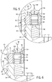
Fig. 5 is a magnified view of the section shown by line 5-5 inFig. 4 ; -
Fig. 6 is a section view similar toFig. 5 illustrating the upward movement of the clamp ring; -
Fig. 7 is an exploded, section view of one of the clamping cylinder assemblies; and -
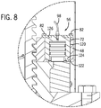
Fig. 8 is a section view showing an alternate configuration for the clamp ring and one of the clamping cylinder assemblies. -
Fig. 1 illustrates a gyratory crusher, such as acone crusher 10, that is operable to crush material, such as rock, stone, or mineral or other substances. Thecone crusher 10 includes acentral opening 12 that receives the material to be crushed. Thecentral opening 12 is defined by afeed bowl hopper 14 which surrounds acone feed plate 16. - As best shown in
Fig. 4 , the feed plate is 16 is mounted to the top of ahead assembly 18 that is gyrationally movable within abowl 20 that supports abowl liner 22. Thehead assembly 18 includes a cone-shapedhead 24 that includes amantle 26. Both themantle 26 and thebowl liner 22 are designed to be a replaceable wear component, since each of these two components define the primary contact surfaces within the crushinggap 28. - As can be understood in
Fig. 4 , thebowl 20 includes a series ofexternal threads 30 that engage a corresponding series ofthreads 32 formed on astationary adjustment ring 34. The interaction between theexternal threads 30 formed on thebowl 20 and thethreads 32 formed on theadjustment ring 34 creates vertical movement of thebowl 20 relative to thestationary adjustment ring 34 upon rotation of thebowl 20. The direction of rotation of thebowl 20 dictates the direction of vertical movement of the bowl relative to theadjustment ring 34. - As can be understood in
Figs. 1 and4 , thebowl 20 is connected to anouter gear ring 36 which is driven by anadjustment motor 38. When theadjustment motor 38 operates, thegear ring 36 rotates, which in turn imparts rotation to thebowl 20 through theadjustment cap 40. Theadjustment cap 40 is securely attached to a top flange 44 of thebowl 20 through a series ofconnectors 46. Rotation of thebowl 20 relative to theadjustment ring 34 causes thebowl 20 to move vertically relative to theadjustment ring 34. - Since the
bowl 20 is designed to be movable relative to thestationary adjustment ring 34 to adjust the size of the crushing gap, thecone crusher 10 of the present disclosure includes aclamp ring 48 that is used to create a clamping force between theexternal threads 30 of thebowl 20 and thethreads 32 of theadjustment ring 34. The clamping force created by theclamp ring 48 prevents rotational movement between thebowl 20 and theadjustment ring 34 during operation of the cone crusher. - As illustrated in
Fig. 4 , theclamp ring 48 includes a series ofthreads 50 that engage theexternal threads 30 formed on thebowl 20. Theclamp ring 48 is an annular member having a generally planartop face 52 and generally planarbottom face 54 as best illustrated inFig. 2 . Theclamp ring 48 includes a plurality of clampingcylinder assemblies 56 that are spaced around theannular clamp ring 48. As shown inFig. 3 , theclamp ring 48 includes eightclamping cylinder assemblies 56 equally spaced around theannular clamp ring 48. Although eightclamping cylinder assemblies 56 are shown in the embodiment of the disclosure, it is contemplated that either a larger or fewer number ofclamping cylinder assemblies 56 could be utilized while operating within the scope of the present disclosure. -
Figs. 5 and7 illustrate one of the plurality of clampingcylinder assemblies 56 positioned within one of thebores 58 formed in theclamp ring 48. As illustrated inFigs. 5 and7 , thebottom face 54 of theclamp ring 48 contacts atop surface 60 of theadjustment ring 34 and a correspondingtop surface 62 of aspacer 64 mounted to anouter surface 66 of theadjustment ring 34. Although aspacer 64 is shown in the drawings, thespacer 64 could be eliminated depending on the configuration of the cone crusher. Thespacer 64 is securely attached to the adjustment ring by welding or bolts and provides a contact surface for theclamping cylinder assemblies 56. The top surfaces 60, 62 are generally coplanar with each other and provide a contact surface for engagement with thelower contact surface 68 of themovable piston 70 that forms part of the clampingcylinder assembly 56. - As shown in
Fig. 7 , the clampingcylinder assembly 56 includes acylinder body 72 including a cylindricalouter wall 74 that is joined to and depends from a mountingflange 76. The mountingflange 76 extends past theouter surface 78 of theouter wall 74 to define asupport shoulder 80 that surrounds theouter wall 74. When the clampingcylinder assembly 56 is installed as shown inFig. 5 , thesupport shoulder 80 contacts thetop surface 52 of theclamp ring 48. - As illustrated in
Fig. 2 , the mountingflange 76 is securely attached to thetop face 52 of theclamp ring 48 by a series of connectors, such asbolts 82. In the embodiment shown, sixbolts 82 are used to attach the mountingflange 76 to thetop face 52. Although sixbolts 82 are shown, fewer oradditional bolts 82 could be utilized depending upon the size of the cone crusher and design requirements. - As illustrated in
Fig. 7 , each of thebolts 82 includes a threadedshaft 84 and ahead 86. The threadedshaft 84 extends through anopening 88 formed in the mountingflange 76 and is received within abore 90 that extends into theclamp ring 48 from thetop face 52. Thebore 90 includes internal threads that engage the threadedshaft 84 of thebolt 82. In this manner, thecylinder body 72 is securely attached to thetop face 52 of theclamp ring 48. - As illustrated in
Fig. 7 , thecylinder body 72 includes an open interior 92 that receives thepiston 70. The top end of theopen interior 92 is closed by apressure head 94 that is welded to the mountingflange 76. Thepressure head 94 includes afluid passageway 96 that allows pressurized hydraulic fluid to travel into the open interior 92 from afluid conduit 98. A pressure fitting 100 receives thefluid conduit 98 and includes a lower, threadedportion 102 that is received within an internally threaded bore formed in thepressure head 94. - As illustrated in
Figs. 5 and7 , thepiston 70 includes aresilient sealing ring 104 positioned in thelowermost groove 106 formed in the body of themovable piston 70. Theresilient sealing ring 104 engages theinner surface 108 of theouter walls 74 to provide a fluid tight seal. A pair of non-metallic wear rings 107are positioned in a pair ofupper grooves 109 to prevent metal-to-metal contact between thepiston 70 and theinner surface 108. As pressurized hydraulic fluid from thefluid conduit 98 is introduced into theopen interior 92 above the top,pressure face 110, the pressure created by the hydraulic fluid forces thepiston 70 downward. The downward movement of thepiston 70 causes thecontact surface 68 to engage thetop surfaces adjustment ring 34 andspacer 64, respectively. - Referring now to
Fig. 5 , when no hydraulic fluid is supplied to theclamping cylinder assembly 56, thethreads 50 formed on theclamp ring 48 and theexternal threads 30 formed on thebowl 20 are loosely in contact with each other. Likewise, thethreads 32 formed on theadjustment ring 34 and theexternal threads 30 are also loosely in contact with each other. In this condition, thebowl 20 can be freely rotated, as shown byarrow 112, to move thebowl 20 vertically relative to thestationary adjustment ring 34. When hydraulic fluid is not supplied to theclamping cylinder assemblies 56 through the individualfluid conduits 98, thebowl 20 can move relative to theadjustment ring 34. - Once the
bowl 20 is in the desired position to define the desired crushing gap, pressurized hydraulic fluid is supplied to each of theclamping cylinder assemblies 56 through the respectivefluid conduits 98. When pressurized hydraulic fluid is supplied to theopen interior 92 above the top,contact surface 110 of thepiston 70, the pressurized hydraulic fluid forces thepiston 70 downward into contact with the top surfaces of both thespacer 64 and theadjustment ring 34. Since both thespacer 64 and theadjustment ring 34 are stationary, the downward movement of thepiston 70 forces theentire clamp ring 48 upward as illustrated byarrows 114 inFig. 6 . - The upward movement of the
clamp ring 48 causes thethreads 50 of the clamping ring to engage theouter threads 30 of thebowl 20. The engagement between thethreads 50 and thethreads 30 causes thebowl 20 to move slightly upward, which causes thethreads 30 of thebowl 20 to engage thethreads 32 of theadjustment ring 34. The engagement between thethreads 30 of thebowl 20 and thethreads 32 of theadjustment ring 34 creates a tight, frictional fit that resists rotational movement of thebowl 20 relative to theadjustment ring 34. Thus, when the cone crusher is in operation, each of theclamping cylinder assemblies 56 is pressurized to create a friction fit between thebowl 20 and theadjustment ring 34, which resist the rotational movement between thebowl 20 and theadjustment ring 34. - During the extended use of the cone crusher, the sealing
ring 104 shown inFig. 7 eventually begins to fail, which causes theclamping cylinder assembly 56 to begin leaking hydraulic fluid. As more and more hydraulic fluid begins to leak out of the clamping cylinder assemblies, it becomes necessary to service theclamping cylinder assemblies 56. In order to access the individualclamping cylinder assemblies 56, it is first necessary to access the clamp ring by initially raising or removing theadjustment cap 40 which is mounted to thebowl 20. Once these components are removed, each of theclamping cylinder assemblies 56 is accessible from the top of thecone crusher 10. Since each of the clamping cylinder assemblies are mounted to thetop face 52 of theclamp ring 48, the individualclamping cylinder assemblies 56 can be removed and replaced by simply removing the series ofbolts 82 and lifting the entireclamping cylinder assembly 56 from within the respective bore contained in theclamp ring 48. Once the clampingcylinder assembly 56 has been serviced, the entireclamping cylinder assembly 56 can be replaced and secured to theclamp ring 48 by retightening theindividual bolts 82. -
Fig. 8 illustrates an alternate arrangement for theclamping cylinder assembly 56. In the embodiment shown inFig. 8 , theclamp ring 48 includes aninner bore 120 having a slightly different configuration than shown in the embodiment ofFigs. 5-7 . In the embodiment shown inFig. 8 , thebore 120 has a step that defines thelower shoulder 122. Thelower shoulder 122 engages and supports acorresponding flange 124 formed on thecylinder body 72. The engagement between theshoulder 122 and theflange 124 prevents movement of thecylinder body 72 downward relative to theclamp ring 48. - The
cylinder body 72 is held within thebore 120 by aseparate mounting flange 126. The mountingflange 126, in turn, is held in place by thebolts 82. In the embodiment shown inFig. 8 , theseparate mounting flange 126 allows the cylinder body to be formed without having to weld the mountingflange 126 to the cylinder body. Thecylinder body 72 is held in place between theflange 126 and thelower shoulder 122 of the stepped bore formed within theclamp ring 48. - As can be understood by the above description, each of the clamping cylinder assemblies can be removed and serviced without requiring the complete removal of feed arrangement, bowl and the clamp ring, as was required in previously available cone crushers.
Claims (11)
- A hydraulic clamping system for use with a gyratory crusher (10) having a head assembly (18) positioned for movement within a bowl (20) that is movable relative to a stationary adjustment ring (34), the system comprising:a clamp ring (48) positioned above the adjustment ring (34) and having a series of threads (50) that are engageable with a series of external threads (30) of the bowl (20), the clamp ring (48) including a top face (52) and a bottom face (54); anda plurality of clamping cylinder assemblies (56); characterized in that the plurality of clamping cylinder assemblies (56) are removably mounted to the top face (52) of the clamp ring (48), wherein each of the clamping cylinder assemblies (56) includes a cylinder body (72) that includes a cylindrical outer wall (74) and that is received within a bore (58; 120) extending through the clamp ring (48) from the top face (52) to the bottom face (54), wherein each of the clamping cylinder assemblies (56) includes a mounting flange (76; 126) connected to the top face (52) of the clamp ring (48) by a plurality of connectors (82), and wherein the mounting flange (76, 126) extends past an outer surface (78) of the outer wall (74) to define a support shoulder (80) that surrounds the outer wall (74).
- The hydraulic clamping system of claim 1 wherein each of the clamping cylinder assemblies (56) includes a movable piston (70) contained within the cylinder body (72), wherein a contact surface (68) of the movable piston (70) engages the adjustment ring (34).
- The hydraulic clamping system of claim 2 further comprising a spacer (64) connected to the adjustment ring (34), where in the contact surface (68) of the piston (70) engages both the adjustment ring (34) and the spacer (64).
- The hydraulic clamping system of claim 1 wherein each of the clamping cylinder assemblies (56) is removable from the top face (52) of the clamp ring (48) while the clamp ring (48) is engaged with the bowl (20).
- The hydraulic clamping system of claim 1 wherein each of the clamping cylinder assemblies (56) is received within one of a plurality of bores (58; 120) that extend through the clamp ring (48) from the top face (52) to the bottom face (54), wherein each of the clamping cylinder assemblies (56) includes a mounting flange (76; 126) securely attached to the top face (52) of the clamp ring (48) by a plurality of connectors (82) such that the clamping cylinder assemblies (56) can be removed by removing the connectors (82).
- A gyratory crusher (10) comprising:a stationary adjustment ring (34) having a series of threads (32);a bowl (20) having a series of external threads (30) that engage the threads formed on the adjustment ring (34);a head assembly (18) positioned for movement within the bowl (20) to create a crushing gap (28) between the head assembly (18) and the bowl (20); anda hydraulic clamping system according to claim 1.
- The gyratory crusher (10) of claim 6 wherein each of the clamping cylinder assemblies (56) includes a movable piston (70) contained within the cylinder body (72), wherein a contact surface (68) of the movable piston (70) engages the adjustment ring (34).
- The gyratory crusher (10) of claim 7 further comprising a spacer (64) connected to the adjustment ring (34), where in the contact surface (68) of the piston (70) engages both the adjustment ring (34) and the spacer (64).
- The gyratory crusher (10) of claim 6 wherein each of the clamping cylinder assemblies (56) is removable from the top face (52) of the clamp ring (48) while the clamp ring is engaged with the bowl (20).
- The gyratory crusher (10) of claim 6 wherein the clamp ring (48) includes a plurality of bores (58; 120) that each extend through the clamp ring (48) from the top face (52) to the bottom face (54), wherein each of the plurality of clamping cylinder assemblies (56) is received within one of the bores (58; 120).
- The gyratory crusher (10) of claim 9 wherein each of the clamping cylinder assemblies (56) is attached to the top face (52) of the clamp ring (48) by a series of connectors (82).
Applications Claiming Priority (2)
| Application Number | Priority Date | Filing Date | Title |
|---|---|---|---|
| US14/463,185 US20160051988A1 (en) | 2014-08-19 | 2014-08-19 | Top service clamping cylinders for a gyratory crusher |
| PCT/US2015/042238 WO2016028444A1 (en) | 2014-08-19 | 2015-07-27 | Top service clamping cylinders for a gyratory crusher |
Publications (3)
| Publication Number | Publication Date |
|---|---|
| EP3183062A1 EP3183062A1 (en) | 2017-06-28 |
| EP3183062B1 true EP3183062B1 (en) | 2021-05-26 |
| EP3183062B8 EP3183062B8 (en) | 2021-06-30 |
Family
ID=53783399
Family Applications (1)
| Application Number | Title | Priority Date | Filing Date |
|---|---|---|---|
| EP15747339.8A Active EP3183062B8 (en) | 2014-08-19 | 2015-07-27 | Top service clamping cylinders for a gyratory crusher |
Country Status (14)
| Country | Link |
|---|---|
| US (1) | US20160051988A1 (en) |
| EP (1) | EP3183062B8 (en) |
| CN (1) | CN106660049B (en) |
| AP (1) | AP2017009734A0 (en) |
| AU (1) | AU2015303921B2 (en) |
| BR (1) | BR112017003189B8 (en) |
| CA (1) | CA2957533C (en) |
| CL (1) | CL2017000330A1 (en) |
| MX (1) | MX383601B (en) |
| PE (1) | PE20170624A1 (en) |
| RU (1) | RU2701965C2 (en) |
| UA (1) | UA121974C2 (en) |
| WO (1) | WO2016028444A1 (en) |
| ZA (1) | ZA201700940B (en) |
Families Citing this family (4)
| Publication number | Priority date | Publication date | Assignee | Title |
|---|---|---|---|---|
| US20190264726A1 (en) * | 2018-02-28 | 2019-08-29 | Caleb Hunter | Mantle Clamp Configuration |
| CN109909010B (en) * | 2019-03-18 | 2020-09-11 | 南京涵铭置智能科技有限公司 | A kind of crushing device and cleaning method which is easy to clean |
| SE2050768A1 (en) * | 2020-06-26 | 2021-12-21 | Metso Outotec Usa Inc | A gyratory crusher, a method for rotating an upper crusher frame and a retrofitting kit |
| US11679389B2 (en) * | 2021-05-21 | 2023-06-20 | Metso Outotec USA Inc. | Mantle retaining system and method for a gyratory crusher |
Family Cites Families (14)
| Publication number | Priority date | Publication date | Assignee | Title |
|---|---|---|---|---|
| US3133708A (en) * | 1961-08-15 | 1964-05-19 | Nordberg Manufacturing Co | Locking mechanism for cone crushers and the like |
| US3337143A (en) * | 1963-11-12 | 1967-08-22 | Louis W Johnson | Rock crusher |
| US3459383A (en) * | 1966-12-23 | 1969-08-05 | Barber Greene Co | Clamping and release means for crusher bowls |
| US3539118A (en) * | 1967-07-27 | 1970-11-10 | Don Kueneman | Gyratory crusher securing and adjusting mechanisms |
| DE2135272A1 (en) * | 1971-07-15 | 1973-01-25 | Kloeckner Humboldt Deutz Ag | CENTRIFUGAL CRUSHER WITH HYDRAULIC PRESSURE DEVICE FOR LIFTING THE HOUSING PART |
| US3759453A (en) * | 1971-12-27 | 1973-09-18 | L Johnson | Rock crusher |
| US4012000A (en) * | 1975-05-27 | 1977-03-15 | Rexnord Inc. | Crushing machine clearing system |
| US3985309A (en) * | 1975-05-27 | 1976-10-12 | Rexnord Inc. | Crusher clearing system |
| SU940835A1 (en) * | 1978-02-09 | 1982-07-07 | Всесоюзный Ордена Трудового Красного Знамени Научно-Исследовательский И Проектный Институт Механической Обработки Полезных Ископаемых | Apparatus for adjusting discharge slot of cone crusher |
| US4198003A (en) * | 1979-03-19 | 1980-04-15 | Barber-Greene Company | Quick release for gyratory crusher concave |
| SE427623B (en) * | 1979-08-14 | 1983-04-25 | Vni I Pi Ural Z Tyazhelogo Mas | Clamping arrangement for a crushing cup |
| US4697745A (en) * | 1986-02-24 | 1987-10-06 | Rexnord Inc. | Method and apparatus for high performance conical crushing |
| RU2219383C2 (en) * | 2001-12-25 | 2003-12-20 | Закрытое акционерное общество "Национальная компания Уралтерминалмаш" | Hydraulic cylinder |
| EP2554269B1 (en) * | 2011-08-01 | 2014-04-16 | Sandvik Intellectual Property AB | Cone crusher and method of preparing cone crusher for operation |
-
2014
- 2014-08-19 US US14/463,185 patent/US20160051988A1/en not_active Abandoned
-
2015
- 2015-02-27 AP AP2017009734A patent/AP2017009734A0/en unknown
- 2015-07-27 RU RU2017108897A patent/RU2701965C2/en active
- 2015-07-27 AU AU2015303921A patent/AU2015303921B2/en active Active
- 2015-07-27 CA CA2957533A patent/CA2957533C/en active Active
- 2015-07-27 PE PE2017000218A patent/PE20170624A1/en unknown
- 2015-07-27 WO PCT/US2015/042238 patent/WO2016028444A1/en not_active Ceased
- 2015-07-27 UA UAA201702454A patent/UA121974C2/en unknown
- 2015-07-27 CN CN201580044519.2A patent/CN106660049B/en active Active
- 2015-07-27 BR BR112017003189A patent/BR112017003189B8/en active IP Right Grant
- 2015-07-27 MX MX2017002164A patent/MX383601B/en unknown
- 2015-07-27 EP EP15747339.8A patent/EP3183062B8/en active Active
-
2017
- 2017-02-07 ZA ZA2017/00940A patent/ZA201700940B/en unknown
- 2017-02-09 CL CL2017000330A patent/CL2017000330A1/en unknown
Non-Patent Citations (1)
| Title |
|---|
| None * |
Also Published As
| Publication number | Publication date |
|---|---|
| MX383601B (en) | 2025-03-14 |
| PE20170624A1 (en) | 2017-06-09 |
| WO2016028444A1 (en) | 2016-02-25 |
| MX2017002164A (en) | 2017-05-23 |
| EP3183062B8 (en) | 2021-06-30 |
| RU2017108897A (en) | 2018-09-20 |
| AU2015303921B2 (en) | 2020-11-12 |
| BR112017003189B1 (en) | 2021-08-10 |
| RU2701965C2 (en) | 2019-10-02 |
| CA2957533C (en) | 2022-08-23 |
| BR112017003189B8 (en) | 2023-03-07 |
| AU2015303921A1 (en) | 2017-02-23 |
| EP3183062A1 (en) | 2017-06-28 |
| CN106660049B (en) | 2019-12-10 |
| RU2017108897A3 (en) | 2019-02-27 |
| BR112017003189A2 (en) | 2017-11-28 |
| AP2017009734A0 (en) | 2017-02-28 |
| CN106660049A (en) | 2017-05-10 |
| ZA201700940B (en) | 2021-08-25 |
| UA121974C2 (en) | 2020-08-25 |
| US20160051988A1 (en) | 2016-02-25 |
| CL2017000330A1 (en) | 2017-09-01 |
| CA2957533A1 (en) | 2016-02-25 |
Similar Documents
| Publication | Publication Date | Title |
|---|---|---|
| EP0022232B1 (en) | Cone crusher | |
| EP2296817B1 (en) | Top service gyratory crusher | |
| CA2957533C (en) | Top service clamping cylinders for a gyratory crusher | |
| US10421075B2 (en) | Grinding apparatus having a rotating receptacle and grinding element | |
| EP2382047B1 (en) | A fastening device, a cone crusher and a method for fastening a mantel to a head of a cone crusher | |
| KR100278063B1 (en) | Method and apparatus for crushing rock | |
| US2901189A (en) | Cone crushing mechanism | |
| EP3094407B1 (en) | Top supported mainshaft suspension system | |
| US6772970B2 (en) | Gyratory crusher spider piston | |
| FI128712B (en) | Vertically divided bowl lining for a concourse and concourse | |
| GB2044633A (en) | Quick release for gyratory crusher concave | |
| CN102834034A (en) | Crusher clearing system | |
| EP2716365B1 (en) | Gyratory crusher bearing | |
| US2310737A (en) | Shaftless cone crusher and tilting member therefor | |
| US2158779A (en) | Crusher | |
| US2634061A (en) | Gyratory crusher | |
| EP3448571B1 (en) | Spider bushing assembly for a gyratory crusher | |
| CA2937698C (en) | System and method for hydraulically removing a socket from a mainshaft of a gyrational crusher | |
| RU132738U1 (en) | HAMMER CRUSHER | |
| US3891153A (en) | Lubricant feed means for gyratory crushers | |
| US10981175B2 (en) | Segmented bowl liner with reusable support cassette | |
| RU2528456C1 (en) | Hammer crusher | |
| RU2601050C1 (en) | Conical crusher with improved attachment of crushing armor |
Legal Events
| Date | Code | Title | Description |
|---|---|---|---|
| STAA | Information on the status of an ep patent application or granted ep patent |
Free format text: STATUS: THE INTERNATIONAL PUBLICATION HAS BEEN MADE |
|
| PUAI | Public reference made under article 153(3) epc to a published international application that has entered the european phase |
Free format text: ORIGINAL CODE: 0009012 |
|
| STAA | Information on the status of an ep patent application or granted ep patent |
Free format text: STATUS: REQUEST FOR EXAMINATION WAS MADE |
|
| 17P | Request for examination filed |
Effective date: 20170210 |
|
| AK | Designated contracting states |
Kind code of ref document: A1 Designated state(s): AL AT BE BG CH CY CZ DE DK EE ES FI FR GB GR HR HU IE IS IT LI LT LU LV MC MK MT NL NO PL PT RO RS SE SI SK SM TR |
|
| AX | Request for extension of the european patent |
Extension state: BA ME |
|
| DAV | Request for validation of the european patent (deleted) | ||
| DAX | Request for extension of the european patent (deleted) | ||
| STAA | Information on the status of an ep patent application or granted ep patent |
Free format text: STATUS: EXAMINATION IS IN PROGRESS |
|
| 17Q | First examination report despatched |
Effective date: 20190307 |
|
| GRAP | Despatch of communication of intention to grant a patent |
Free format text: ORIGINAL CODE: EPIDOSNIGR1 |
|
| STAA | Information on the status of an ep patent application or granted ep patent |
Free format text: STATUS: GRANT OF PATENT IS INTENDED |
|
| INTG | Intention to grant announced |
Effective date: 20201223 |
|
| GRAS | Grant fee paid |
Free format text: ORIGINAL CODE: EPIDOSNIGR3 |
|
| GRAA | (expected) grant |
Free format text: ORIGINAL CODE: 0009210 |
|
| STAA | Information on the status of an ep patent application or granted ep patent |
Free format text: STATUS: THE PATENT HAS BEEN GRANTED |
|
| AK | Designated contracting states |
Kind code of ref document: B1 Designated state(s): AL AT BE BG CH CY CZ DE DK EE ES FI FR GB GR HR HU IE IS IT LI LT LU LV MC MK MT NL NO PL PT RO RS SE SI SK SM TR |
|
| REG | Reference to a national code |
Ref country code: GB Ref legal event code: FG4D |
|
| REG | Reference to a national code |
Ref country code: DE Ref legal event code: R081 Ref document number: 602015069716 Country of ref document: DE Owner name: METSO OUTOTEC USA INC., BROOKFIELD, US Free format text: FORMER OWNER: METSO MINERALS INDUSTRIES, INC., WAUKESHA, WI, US Ref country code: DE Ref legal event code: R081 Ref document number: 602015069716 Country of ref document: DE Owner name: METSO USA INC. (N.D.GES.D.STAATES DELAWARE), B, US Free format text: FORMER OWNER: METSO MINERALS INDUSTRIES, INC., WAUKESHA, WI, US Ref country code: CH Ref legal event code: EP Ref country code: CH Ref legal event code: PK Free format text: BERICHTIGUNG B8 Ref country code: DE Ref legal event code: R081 Ref document number: 602015069716 Country of ref document: DE Owner name: METSO OUTOTEC USA INC., WAUKESHA, US Free format text: FORMER OWNER: METSO MINERALS INDUSTRIES, INC., WAUKESHA, WI, US |
|
| REG | Reference to a national code |
Ref country code: AT Ref legal event code: REF Ref document number: 1395682 Country of ref document: AT Kind code of ref document: T Effective date: 20210615 |
|
| RAP2 | Party data changed (patent owner data changed or rights of a patent transferred) |
Owner name: METSO OUTOTEC USA INC. |
|
| REG | Reference to a national code |
Ref country code: DE Ref legal event code: R096 Ref document number: 602015069716 Country of ref document: DE |
|
| REG | Reference to a national code |
Ref country code: IE Ref legal event code: FG4D |
|
| REG | Reference to a national code |
Ref country code: SE Ref legal event code: TRGR |
|
| REG | Reference to a national code |
Ref country code: FI Ref legal event code: FGE |
|
| REG | Reference to a national code |
Ref country code: NO Ref legal event code: T2 Effective date: 20210526 |
|
| REG | Reference to a national code |
Ref country code: LT Ref legal event code: MG9D |
|
| REG | Reference to a national code |
Ref country code: AT Ref legal event code: MK05 Ref document number: 1395682 Country of ref document: AT Kind code of ref document: T Effective date: 20210526 |
|
| PG25 | Lapsed in a contracting state [announced via postgrant information from national office to epo] |
Ref country code: LT Free format text: LAPSE BECAUSE OF FAILURE TO SUBMIT A TRANSLATION OF THE DESCRIPTION OR TO PAY THE FEE WITHIN THE PRESCRIBED TIME-LIMIT Effective date: 20210526 Ref country code: HR Free format text: LAPSE BECAUSE OF FAILURE TO SUBMIT A TRANSLATION OF THE DESCRIPTION OR TO PAY THE FEE WITHIN THE PRESCRIBED TIME-LIMIT Effective date: 20210526 Ref country code: BG Free format text: LAPSE BECAUSE OF FAILURE TO SUBMIT A TRANSLATION OF THE DESCRIPTION OR TO PAY THE FEE WITHIN THE PRESCRIBED TIME-LIMIT Effective date: 20210826 Ref country code: AT Free format text: LAPSE BECAUSE OF FAILURE TO SUBMIT A TRANSLATION OF THE DESCRIPTION OR TO PAY THE FEE WITHIN THE PRESCRIBED TIME-LIMIT Effective date: 20210526 |
|
| REG | Reference to a national code |
Ref country code: NL Ref legal event code: MP Effective date: 20210526 Ref country code: GB Ref legal event code: 732E Free format text: REGISTERED BETWEEN 20211007 AND 20211013 |
|
| PG25 | Lapsed in a contracting state [announced via postgrant information from national office to epo] |
Ref country code: PT Free format text: LAPSE BECAUSE OF FAILURE TO SUBMIT A TRANSLATION OF THE DESCRIPTION OR TO PAY THE FEE WITHIN THE PRESCRIBED TIME-LIMIT Effective date: 20210927 Ref country code: PL Free format text: LAPSE BECAUSE OF FAILURE TO SUBMIT A TRANSLATION OF THE DESCRIPTION OR TO PAY THE FEE WITHIN THE PRESCRIBED TIME-LIMIT Effective date: 20210526 Ref country code: RS Free format text: LAPSE BECAUSE OF FAILURE TO SUBMIT A TRANSLATION OF THE DESCRIPTION OR TO PAY THE FEE WITHIN THE PRESCRIBED TIME-LIMIT Effective date: 20210526 Ref country code: IS Free format text: LAPSE BECAUSE OF FAILURE TO SUBMIT A TRANSLATION OF THE DESCRIPTION OR TO PAY THE FEE WITHIN THE PRESCRIBED TIME-LIMIT Effective date: 20210926 Ref country code: LV Free format text: LAPSE BECAUSE OF FAILURE TO SUBMIT A TRANSLATION OF THE DESCRIPTION OR TO PAY THE FEE WITHIN THE PRESCRIBED TIME-LIMIT Effective date: 20210526 Ref country code: GR Free format text: LAPSE BECAUSE OF FAILURE TO SUBMIT A TRANSLATION OF THE DESCRIPTION OR TO PAY THE FEE WITHIN THE PRESCRIBED TIME-LIMIT Effective date: 20210827 |
|
| PG25 | Lapsed in a contracting state [announced via postgrant information from national office to epo] |
Ref country code: NL Free format text: LAPSE BECAUSE OF FAILURE TO SUBMIT A TRANSLATION OF THE DESCRIPTION OR TO PAY THE FEE WITHIN THE PRESCRIBED TIME-LIMIT Effective date: 20210526 |
|
| PG25 | Lapsed in a contracting state [announced via postgrant information from national office to epo] |
Ref country code: ES Free format text: LAPSE BECAUSE OF FAILURE TO SUBMIT A TRANSLATION OF THE DESCRIPTION OR TO PAY THE FEE WITHIN THE PRESCRIBED TIME-LIMIT Effective date: 20210526 Ref country code: RO Free format text: LAPSE BECAUSE OF FAILURE TO SUBMIT A TRANSLATION OF THE DESCRIPTION OR TO PAY THE FEE WITHIN THE PRESCRIBED TIME-LIMIT Effective date: 20210526 Ref country code: EE Free format text: LAPSE BECAUSE OF FAILURE TO SUBMIT A TRANSLATION OF THE DESCRIPTION OR TO PAY THE FEE WITHIN THE PRESCRIBED TIME-LIMIT Effective date: 20210526 Ref country code: CZ Free format text: LAPSE BECAUSE OF FAILURE TO SUBMIT A TRANSLATION OF THE DESCRIPTION OR TO PAY THE FEE WITHIN THE PRESCRIBED TIME-LIMIT Effective date: 20210526 Ref country code: DK Free format text: LAPSE BECAUSE OF FAILURE TO SUBMIT A TRANSLATION OF THE DESCRIPTION OR TO PAY THE FEE WITHIN THE PRESCRIBED TIME-LIMIT Effective date: 20210526 Ref country code: SM Free format text: LAPSE BECAUSE OF FAILURE TO SUBMIT A TRANSLATION OF THE DESCRIPTION OR TO PAY THE FEE WITHIN THE PRESCRIBED TIME-LIMIT Effective date: 20210526 Ref country code: SK Free format text: LAPSE BECAUSE OF FAILURE TO SUBMIT A TRANSLATION OF THE DESCRIPTION OR TO PAY THE FEE WITHIN THE PRESCRIBED TIME-LIMIT Effective date: 20210526 |
|
| REG | Reference to a national code |
Ref country code: CH Ref legal event code: PL |
|
| REG | Reference to a national code |
Ref country code: DE Ref legal event code: R097 Ref document number: 602015069716 Country of ref document: DE |
|
| PLBE | No opposition filed within time limit |
Free format text: ORIGINAL CODE: 0009261 |
|
| STAA | Information on the status of an ep patent application or granted ep patent |
Free format text: STATUS: NO OPPOSITION FILED WITHIN TIME LIMIT |
|
| PG25 | Lapsed in a contracting state [announced via postgrant information from national office to epo] |
Ref country code: MC Free format text: LAPSE BECAUSE OF FAILURE TO SUBMIT A TRANSLATION OF THE DESCRIPTION OR TO PAY THE FEE WITHIN THE PRESCRIBED TIME-LIMIT Effective date: 20210526 |
|
| REG | Reference to a national code |
Ref country code: BE Ref legal event code: MM Effective date: 20210731 |
|
| PG25 | Lapsed in a contracting state [announced via postgrant information from national office to epo] |
Ref country code: LI Free format text: LAPSE BECAUSE OF NON-PAYMENT OF DUE FEES Effective date: 20210731 Ref country code: CH Free format text: LAPSE BECAUSE OF NON-PAYMENT OF DUE FEES Effective date: 20210731 |
|
| 26N | No opposition filed |
Effective date: 20220301 |
|
| PG25 | Lapsed in a contracting state [announced via postgrant information from national office to epo] |
Ref country code: IS Free format text: LAPSE BECAUSE OF FAILURE TO SUBMIT A TRANSLATION OF THE DESCRIPTION OR TO PAY THE FEE WITHIN THE PRESCRIBED TIME-LIMIT Effective date: 20210926 Ref country code: LU Free format text: LAPSE BECAUSE OF NON-PAYMENT OF DUE FEES Effective date: 20210727 Ref country code: AL Free format text: LAPSE BECAUSE OF FAILURE TO SUBMIT A TRANSLATION OF THE DESCRIPTION OR TO PAY THE FEE WITHIN THE PRESCRIBED TIME-LIMIT Effective date: 20210526 |
|
| PG25 | Lapsed in a contracting state [announced via postgrant information from national office to epo] |
Ref country code: IT Free format text: LAPSE BECAUSE OF FAILURE TO SUBMIT A TRANSLATION OF THE DESCRIPTION OR TO PAY THE FEE WITHIN THE PRESCRIBED TIME-LIMIT Effective date: 20210526 Ref country code: IE Free format text: LAPSE BECAUSE OF NON-PAYMENT OF DUE FEES Effective date: 20210727 Ref country code: BE Free format text: LAPSE BECAUSE OF NON-PAYMENT OF DUE FEES Effective date: 20210731 |
|
| REG | Reference to a national code |
Ref country code: NO Ref legal event code: CREP Representative=s name: PLOUGMANN VINGTOFT, POSTBOKS 1003 SENTRUM, 0104 Ref country code: NO Ref legal event code: CHAD Owner name: METSO OUTOTEC USA INC., US |
|
| REG | Reference to a national code |
Ref country code: DE Ref legal event code: R081 Ref document number: 602015069716 Country of ref document: DE Owner name: METSO OUTOTEC USA INC., BROOKFIELD, US Free format text: FORMER OWNER: METSO OUTOTEC USA INC., WAUKESHA, WI, US Ref country code: DE Ref legal event code: R081 Ref document number: 602015069716 Country of ref document: DE Owner name: METSO USA INC. (N.D.GES.D.STAATES DELAWARE), B, US Free format text: FORMER OWNER: METSO OUTOTEC USA INC., WAUKESHA, WI, US |
|
| PG25 | Lapsed in a contracting state [announced via postgrant information from national office to epo] |
Ref country code: HU Free format text: LAPSE BECAUSE OF FAILURE TO SUBMIT A TRANSLATION OF THE DESCRIPTION OR TO PAY THE FEE WITHIN THE PRESCRIBED TIME-LIMIT; INVALID AB INITIO Effective date: 20150727 |
|
| PG25 | Lapsed in a contracting state [announced via postgrant information from national office to epo] |
Ref country code: CY Free format text: LAPSE BECAUSE OF FAILURE TO SUBMIT A TRANSLATION OF THE DESCRIPTION OR TO PAY THE FEE WITHIN THE PRESCRIBED TIME-LIMIT Effective date: 20210526 |
|
| P01 | Opt-out of the competence of the unified patent court (upc) registered |
Effective date: 20230527 |
|
| PG25 | Lapsed in a contracting state [announced via postgrant information from national office to epo] |
Ref country code: MK Free format text: LAPSE BECAUSE OF FAILURE TO SUBMIT A TRANSLATION OF THE DESCRIPTION OR TO PAY THE FEE WITHIN THE PRESCRIBED TIME-LIMIT Effective date: 20210526 |
|
| PG25 | Lapsed in a contracting state [announced via postgrant information from national office to epo] |
Ref country code: MT Free format text: LAPSE BECAUSE OF FAILURE TO SUBMIT A TRANSLATION OF THE DESCRIPTION OR TO PAY THE FEE WITHIN THE PRESCRIBED TIME-LIMIT Effective date: 20210526 |
|
| REG | Reference to a national code |
Ref country code: DE Ref legal event code: R081 Ref document number: 602015069716 Country of ref document: DE Owner name: METSO USA INC. (N.D.GES.D.STAATES DELAWARE), B, US Free format text: FORMER OWNER: METSO OUTOTEC USA INC., BROOKFIELD, WI, US |
|
| PGFP | Annual fee paid to national office [announced via postgrant information from national office to epo] |
Ref country code: GB Payment date: 20250605 Year of fee payment: 11 |
|
| PGFP | Annual fee paid to national office [announced via postgrant information from national office to epo] |
Ref country code: FR Payment date: 20250623 Year of fee payment: 11 |
|
| PGFP | Annual fee paid to national office [announced via postgrant information from national office to epo] |
Ref country code: SE Payment date: 20250610 Year of fee payment: 11 |
|
| PGFP | Annual fee paid to national office [announced via postgrant information from national office to epo] |
Ref country code: FI Payment date: 20250715 Year of fee payment: 11 |
|
| PGFP | Annual fee paid to national office [announced via postgrant information from national office to epo] |
Ref country code: DE Payment date: 20250604 Year of fee payment: 11 |
|
| PGFP | Annual fee paid to national office [announced via postgrant information from national office to epo] |
Ref country code: NO Payment date: 20250709 Year of fee payment: 11 |
|
| PGFP | Annual fee paid to national office [announced via postgrant information from national office to epo] |
Ref country code: TR Payment date: 20250710 Year of fee payment: 11 |