EP3183033B1 - Dispositif de neurostimulation non-invasive efficace à l'aide de séquences d'excitation variables - Google Patents
Dispositif de neurostimulation non-invasive efficace à l'aide de séquences d'excitation variables Download PDFInfo
- Publication number
- EP3183033B1 EP3183033B1 EP15801158.5A EP15801158A EP3183033B1 EP 3183033 B1 EP3183033 B1 EP 3183033B1 EP 15801158 A EP15801158 A EP 15801158A EP 3183033 B1 EP3183033 B1 EP 3183033B1
- Authority
- EP
- European Patent Office
- Prior art keywords
- stimuli
- stimulation
- generated
- accordance
- sequences
- Prior art date
- Legal status (The legal status is an assumption and is not a legal conclusion. Google has not performed a legal analysis and makes no representation as to the accuracy of the status listed.)
- Active
Links
- 230000000638 stimulation Effects 0.000 claims description 257
- 210000002569 neuron Anatomy 0.000 claims description 59
- 230000001537 neural effect Effects 0.000 claims description 51
- 230000001360 synchronised effect Effects 0.000 claims description 34
- 210000004556 brain Anatomy 0.000 claims description 25
- 230000003534 oscillatory effect Effects 0.000 claims description 25
- 230000000007 visual effect Effects 0.000 claims description 18
- 230000001575 pathological effect Effects 0.000 claims description 17
- 210000000278 spinal cord Anatomy 0.000 claims description 13
- 238000002604 ultrasonography Methods 0.000 claims description 9
- 230000001339 gustatory effect Effects 0.000 claims description 6
- 230000010355 oscillation Effects 0.000 claims description 5
- 230000003252 repetitive effect Effects 0.000 claims description 3
- 230000004936 stimulating effect Effects 0.000 claims description 3
- 238000004590 computer program Methods 0.000 claims 1
- 108091006146 Channels Proteins 0.000 description 52
- 230000000694 effects Effects 0.000 description 20
- 238000004088 simulation Methods 0.000 description 16
- 210000003491 skin Anatomy 0.000 description 16
- 108020003175 receptors Proteins 0.000 description 15
- 230000004044 response Effects 0.000 description 14
- 238000000537 electroencephalography Methods 0.000 description 12
- 208000009205 Tinnitus Diseases 0.000 description 11
- 238000005259 measurement Methods 0.000 description 11
- 230000002969 morbid Effects 0.000 description 11
- 231100000886 tinnitus Toxicity 0.000 description 10
- 208000037265 diseases, disorders, signs and symptoms Diseases 0.000 description 7
- 230000007794 irritation Effects 0.000 description 7
- 238000000034 method Methods 0.000 description 7
- 238000004458 analytical method Methods 0.000 description 6
- 230000005540 biological transmission Effects 0.000 description 6
- 201000010099 disease Diseases 0.000 description 6
- 210000000653 nervous system Anatomy 0.000 description 6
- 206010044565 Tremor Diseases 0.000 description 5
- 238000000354 decomposition reaction Methods 0.000 description 5
- 230000006870 function Effects 0.000 description 5
- 210000001525 retina Anatomy 0.000 description 5
- 230000033764 rhythmic process Effects 0.000 description 5
- 208000012902 Nervous system disease Diseases 0.000 description 4
- 208000025966 Neurological disease Diseases 0.000 description 4
- 208000018737 Parkinson disease Diseases 0.000 description 4
- 230000008878 coupling Effects 0.000 description 4
- 238000010168 coupling process Methods 0.000 description 4
- 238000005859 coupling reaction Methods 0.000 description 4
- 230000003993 interaction Effects 0.000 description 4
- 230000000926 neurological effect Effects 0.000 description 4
- 230000004007 neuromodulation Effects 0.000 description 4
- 208000020016 psychiatric disease Diseases 0.000 description 4
- 230000001020 rhythmical effect Effects 0.000 description 4
- 230000000946 synaptic effect Effects 0.000 description 4
- 208000019695 Migraine disease Diseases 0.000 description 3
- 210000003926 auditory cortex Anatomy 0.000 description 3
- 230000000875 corresponding effect Effects 0.000 description 3
- 230000001419 dependent effect Effects 0.000 description 3
- 210000003027 ear inner Anatomy 0.000 description 3
- 206010015037 epilepsy Diseases 0.000 description 3
- 238000001914 filtration Methods 0.000 description 3
- 238000002582 magnetoencephalography Methods 0.000 description 3
- 206010027599 migraine Diseases 0.000 description 3
- 230000002602 somatotopic effect Effects 0.000 description 3
- 238000011491 transcranial magnetic stimulation Methods 0.000 description 3
- 230000009466 transformation Effects 0.000 description 3
- 208000014094 Dystonic disease Diseases 0.000 description 2
- 208000008454 Hyperhidrosis Diseases 0.000 description 2
- 208000021384 Obsessive-Compulsive disease Diseases 0.000 description 2
- 230000036982 action potential Effects 0.000 description 2
- 230000004913 activation Effects 0.000 description 2
- 238000013528 artificial neural network Methods 0.000 description 2
- 210000003403 autonomic nervous system Anatomy 0.000 description 2
- 210000004227 basal ganglia Anatomy 0.000 description 2
- 208000030963 borderline personality disease Diseases 0.000 description 2
- 210000003710 cerebral cortex Anatomy 0.000 description 2
- 230000001684 chronic effect Effects 0.000 description 2
- 230000002596 correlated effect Effects 0.000 description 2
- 238000011161 development Methods 0.000 description 2
- 230000018109 developmental process Effects 0.000 description 2
- 208000010118 dystonia Diseases 0.000 description 2
- 238000002567 electromyography Methods 0.000 description 2
- 201000006517 essential tremor Diseases 0.000 description 2
- 238000010304 firing Methods 0.000 description 2
- 239000011521 glass Substances 0.000 description 2
- 210000003128 head Anatomy 0.000 description 2
- 230000006872 improvement Effects 0.000 description 2
- 208000002551 irritable bowel syndrome Diseases 0.000 description 2
- 230000002045 lasting effect Effects 0.000 description 2
- 230000008095 long lasting therapeutic effect Effects 0.000 description 2
- 210000003205 muscle Anatomy 0.000 description 2
- 230000003387 muscular Effects 0.000 description 2
- 210000005036 nerve Anatomy 0.000 description 2
- 230000007830 nerve conduction Effects 0.000 description 2
- 230000037361 pathway Effects 0.000 description 2
- 230000008569 process Effects 0.000 description 2
- 201000000980 schizophrenia Diseases 0.000 description 2
- 230000001953 sensory effect Effects 0.000 description 2
- 208000023516 stroke disease Diseases 0.000 description 2
- 238000007920 subcutaneous administration Methods 0.000 description 2
- 208000024891 symptom Diseases 0.000 description 2
- 235000019640 taste Nutrition 0.000 description 2
- 210000002435 tendon Anatomy 0.000 description 2
- 210000001103 thalamus Anatomy 0.000 description 2
- 230000001225 therapeutic effect Effects 0.000 description 2
- 206010001541 Akinesia Diseases 0.000 description 1
- 241001261858 Alsodes Species 0.000 description 1
- 208000024827 Alzheimer disease Diseases 0.000 description 1
- 206010003591 Ataxia Diseases 0.000 description 1
- 208000006096 Attention Deficit Disorder with Hyperactivity Diseases 0.000 description 1
- 208000036864 Attention deficit/hyperactivity disease Diseases 0.000 description 1
- 206010003805 Autism Diseases 0.000 description 1
- 208000020706 Autistic disease Diseases 0.000 description 1
- 206010065369 Burnout syndrome Diseases 0.000 description 1
- 208000015879 Cerebellar disease Diseases 0.000 description 1
- 208000018152 Cerebral disease Diseases 0.000 description 1
- 208000006561 Cluster Headache Diseases 0.000 description 1
- 206010010904 Convulsion Diseases 0.000 description 1
- 206010012289 Dementia Diseases 0.000 description 1
- 206010012335 Dependence Diseases 0.000 description 1
- 208000030814 Eating disease Diseases 0.000 description 1
- 208000019454 Feeding and Eating disease Diseases 0.000 description 1
- 208000001640 Fibromyalgia Diseases 0.000 description 1
- 206010019233 Headaches Diseases 0.000 description 1
- 206010020772 Hypertension Diseases 0.000 description 1
- 208000016285 Movement disease Diseases 0.000 description 1
- 208000008238 Muscle Spasticity Diseases 0.000 description 1
- 206010029333 Neurosis Diseases 0.000 description 1
- 206010034158 Pathological gambling Diseases 0.000 description 1
- 208000029033 Spinal Cord disease Diseases 0.000 description 1
- 208000006011 Stroke Diseases 0.000 description 1
- 208000000323 Tourette Syndrome Diseases 0.000 description 1
- 208000016620 Tourette disease Diseases 0.000 description 1
- 206010049155 Visual brightness Diseases 0.000 description 1
- 230000002159 abnormal effect Effects 0.000 description 1
- 230000001133 acceleration Effects 0.000 description 1
- 208000022531 anorexia Diseases 0.000 description 1
- 230000000712 assembly Effects 0.000 description 1
- 238000000429 assembly Methods 0.000 description 1
- 208000015802 attention deficit-hyperactivity disease Diseases 0.000 description 1
- 210000000746 body region Anatomy 0.000 description 1
- 230000007177 brain activity Effects 0.000 description 1
- 230000002490 cerebral effect Effects 0.000 description 1
- 230000008859 change Effects 0.000 description 1
- 208000022371 chronic pain syndrome Diseases 0.000 description 1
- 208000018912 cluster headache syndrome Diseases 0.000 description 1
- 210000000860 cochlear nerve Anatomy 0.000 description 1
- 238000004891 communication Methods 0.000 description 1
- 239000002131 composite material Substances 0.000 description 1
- 235000009508 confectionery Nutrition 0.000 description 1
- 230000001276 controlling effect Effects 0.000 description 1
- 235000019788 craving Nutrition 0.000 description 1
- 230000009849 deactivation Effects 0.000 description 1
- 206010061428 decreased appetite Diseases 0.000 description 1
- 230000006735 deficit Effects 0.000 description 1
- 238000013461 design Methods 0.000 description 1
- 208000035475 disorder Diseases 0.000 description 1
- 235000014632 disordered eating Nutrition 0.000 description 1
- 210000000613 ear canal Anatomy 0.000 description 1
- 230000001747 exhibiting effect Effects 0.000 description 1
- 210000003414 extremity Anatomy 0.000 description 1
- 210000000245 forearm Anatomy 0.000 description 1
- 210000003780 hair follicle Anatomy 0.000 description 1
- 231100000869 headache Toxicity 0.000 description 1
- 230000036541 health Effects 0.000 description 1
- 229940088597 hormone Drugs 0.000 description 1
- 239000005556 hormone Substances 0.000 description 1
- 230000002401 inhibitory effect Effects 0.000 description 1
- 210000002414 leg Anatomy 0.000 description 1
- 239000007788 liquid Substances 0.000 description 1
- 230000005923 long-lasting effect Effects 0.000 description 1
- 238000013507 mapping Methods 0.000 description 1
- 239000003550 marker Substances 0.000 description 1
- 210000000716 merkel cell Anatomy 0.000 description 1
- 230000036651 mood Effects 0.000 description 1
- 210000004400 mucous membrane Anatomy 0.000 description 1
- 201000006417 multiple sclerosis Diseases 0.000 description 1
- 210000004126 nerve fiber Anatomy 0.000 description 1
- 208000004296 neuralgia Diseases 0.000 description 1
- 208000015238 neurotic disease Diseases 0.000 description 1
- 210000001328 optic nerve Anatomy 0.000 description 1
- 230000003287 optical effect Effects 0.000 description 1
- 201000003471 ovarian fetiform teratoma Diseases 0.000 description 1
- 206010033675 panniculitis Diseases 0.000 description 1
- 210000000578 peripheral nerve Anatomy 0.000 description 1
- 210000000976 primary motor cortex Anatomy 0.000 description 1
- 230000002035 prolonged effect Effects 0.000 description 1
- 230000005855 radiation Effects 0.000 description 1
- 230000009467 reduction Effects 0.000 description 1
- 238000007634 remodeling Methods 0.000 description 1
- 230000035807 sensation Effects 0.000 description 1
- 235000019615 sensations Nutrition 0.000 description 1
- 230000035945 sensitivity Effects 0.000 description 1
- 230000035909 sensory irritation Effects 0.000 description 1
- 208000019116 sleep disease Diseases 0.000 description 1
- 208000018198 spasticity Diseases 0.000 description 1
- 238000001228 spectrum Methods 0.000 description 1
- 238000010183 spectrum analysis Methods 0.000 description 1
- 238000000528 statistical test Methods 0.000 description 1
- 210000004304 subcutaneous tissue Anatomy 0.000 description 1
- 230000035900 sweating Effects 0.000 description 1
- 208000011580 syndromic disease Diseases 0.000 description 1
- 238000012731 temporal analysis Methods 0.000 description 1
- 230000002123 temporal effect Effects 0.000 description 1
- 238000012360 testing method Methods 0.000 description 1
- 238000002560 therapeutic procedure Methods 0.000 description 1
- 210000003051 thermoreceptor Anatomy 0.000 description 1
- 108091008689 thermoreceptors Proteins 0.000 description 1
- 208000016686 tic disease Diseases 0.000 description 1
- 238000000700 time series analysis Methods 0.000 description 1
- 230000001052 transient effect Effects 0.000 description 1
- 235000019583 umami taste Nutrition 0.000 description 1
- 210000000689 upper leg Anatomy 0.000 description 1
- 238000011179 visual inspection Methods 0.000 description 1
Images


Classifications
-
- A—HUMAN NECESSITIES
- A61—MEDICAL OR VETERINARY SCIENCE; HYGIENE
- A61B—DIAGNOSIS; SURGERY; IDENTIFICATION
- A61B5/00—Measuring for diagnostic purposes; Identification of persons
- A61B5/40—Detecting, measuring or recording for evaluating the nervous system
- A61B5/4076—Diagnosing or monitoring particular conditions of the nervous system
- A61B5/4082—Diagnosing or monitoring movement diseases, e.g. Parkinson, Huntington or Tourette
-
- A—HUMAN NECESSITIES
- A61—MEDICAL OR VETERINARY SCIENCE; HYGIENE
- A61B—DIAGNOSIS; SURGERY; IDENTIFICATION
- A61B5/00—Measuring for diagnostic purposes; Identification of persons
- A61B5/40—Detecting, measuring or recording for evaluating the nervous system
- A61B5/4076—Diagnosing or monitoring particular conditions of the nervous system
- A61B5/4094—Diagnosing or monitoring seizure diseases, e.g. epilepsy
-
- A—HUMAN NECESSITIES
- A61—MEDICAL OR VETERINARY SCIENCE; HYGIENE
- A61M—DEVICES FOR INTRODUCING MEDIA INTO, OR ONTO, THE BODY; DEVICES FOR TRANSDUCING BODY MEDIA OR FOR TAKING MEDIA FROM THE BODY; DEVICES FOR PRODUCING OR ENDING SLEEP OR STUPOR
- A61M21/00—Other devices or methods to cause a change in the state of consciousness; Devices for producing or ending sleep by mechanical, optical, or acoustical means, e.g. for hypnosis
-
- A—HUMAN NECESSITIES
- A61—MEDICAL OR VETERINARY SCIENCE; HYGIENE
- A61N—ELECTROTHERAPY; MAGNETOTHERAPY; RADIATION THERAPY; ULTRASOUND THERAPY
- A61N1/00—Electrotherapy; Circuits therefor
- A61N1/18—Applying electric currents by contact electrodes
- A61N1/32—Applying electric currents by contact electrodes alternating or intermittent currents
- A61N1/36—Applying electric currents by contact electrodes alternating or intermittent currents for stimulation
- A61N1/36014—External stimulators, e.g. with patch electrodes
- A61N1/36025—External stimulators, e.g. with patch electrodes for treating a mental or cerebral condition
-
- A—HUMAN NECESSITIES
- A61—MEDICAL OR VETERINARY SCIENCE; HYGIENE
- A61N—ELECTROTHERAPY; MAGNETOTHERAPY; RADIATION THERAPY; ULTRASOUND THERAPY
- A61N1/00—Electrotherapy; Circuits therefor
- A61N1/18—Applying electric currents by contact electrodes
- A61N1/32—Applying electric currents by contact electrodes alternating or intermittent currents
- A61N1/36—Applying electric currents by contact electrodes alternating or intermittent currents for stimulation
- A61N1/3605—Implantable neurostimulators for stimulating central or peripheral nerve system
- A61N1/36128—Control systems
- A61N1/36146—Control systems specified by the stimulation parameters
- A61N1/36167—Timing, e.g. stimulation onset
- A61N1/36175—Pulse width or duty cycle
-
- A—HUMAN NECESSITIES
- A61—MEDICAL OR VETERINARY SCIENCE; HYGIENE
- A61B—DIAGNOSIS; SURGERY; IDENTIFICATION
- A61B2562/00—Details of sensors; Constructional details of sensor housings or probes; Accessories for sensors
- A61B2562/02—Details of sensors specially adapted for in-vivo measurements
- A61B2562/0219—Inertial sensors, e.g. accelerometers, gyroscopes, tilt switches
-
- A—HUMAN NECESSITIES
- A61—MEDICAL OR VETERINARY SCIENCE; HYGIENE
- A61B—DIAGNOSIS; SURGERY; IDENTIFICATION
- A61B5/00—Measuring for diagnostic purposes; Identification of persons
- A61B5/24—Detecting, measuring or recording bioelectric or biomagnetic signals of the body or parts thereof
- A61B5/25—Bioelectric electrodes therefor
- A61B5/279—Bioelectric electrodes therefor specially adapted for particular uses
- A61B5/291—Bioelectric electrodes therefor specially adapted for particular uses for electroencephalography [EEG]
-
- A—HUMAN NECESSITIES
- A61—MEDICAL OR VETERINARY SCIENCE; HYGIENE
- A61B—DIAGNOSIS; SURGERY; IDENTIFICATION
- A61B5/00—Measuring for diagnostic purposes; Identification of persons
- A61B5/24—Detecting, measuring or recording bioelectric or biomagnetic signals of the body or parts thereof
- A61B5/316—Modalities, i.e. specific diagnostic methods
- A61B5/369—Electroencephalography [EEG]
-
- A—HUMAN NECESSITIES
- A61—MEDICAL OR VETERINARY SCIENCE; HYGIENE
- A61B—DIAGNOSIS; SURGERY; IDENTIFICATION
- A61B5/00—Measuring for diagnostic purposes; Identification of persons
- A61B5/24—Detecting, measuring or recording bioelectric or biomagnetic signals of the body or parts thereof
- A61B5/316—Modalities, i.e. specific diagnostic methods
- A61B5/389—Electromyography [EMG]
-
- A—HUMAN NECESSITIES
- A61—MEDICAL OR VETERINARY SCIENCE; HYGIENE
- A61B—DIAGNOSIS; SURGERY; IDENTIFICATION
- A61B5/00—Measuring for diagnostic purposes; Identification of persons
- A61B5/40—Detecting, measuring or recording for evaluating the nervous system
- A61B5/4058—Detecting, measuring or recording for evaluating the nervous system for evaluating the central nervous system
- A61B5/4064—Evaluating the brain
-
- A—HUMAN NECESSITIES
- A61—MEDICAL OR VETERINARY SCIENCE; HYGIENE
- A61B—DIAGNOSIS; SURGERY; IDENTIFICATION
- A61B5/00—Measuring for diagnostic purposes; Identification of persons
- A61B5/40—Detecting, measuring or recording for evaluating the nervous system
- A61B5/4076—Diagnosing or monitoring particular conditions of the nervous system
- A61B5/4088—Diagnosing of monitoring cognitive diseases, e.g. Alzheimer, prion diseases or dementia
-
- A—HUMAN NECESSITIES
- A61—MEDICAL OR VETERINARY SCIENCE; HYGIENE
- A61B—DIAGNOSIS; SURGERY; IDENTIFICATION
- A61B5/00—Measuring for diagnostic purposes; Identification of persons
- A61B5/48—Other medical applications
- A61B5/4836—Diagnosis combined with treatment in closed-loop systems or methods
-
- A—HUMAN NECESSITIES
- A61—MEDICAL OR VETERINARY SCIENCE; HYGIENE
- A61M—DEVICES FOR INTRODUCING MEDIA INTO, OR ONTO, THE BODY; DEVICES FOR TRANSDUCING BODY MEDIA OR FOR TAKING MEDIA FROM THE BODY; DEVICES FOR PRODUCING OR ENDING SLEEP OR STUPOR
- A61M21/00—Other devices or methods to cause a change in the state of consciousness; Devices for producing or ending sleep by mechanical, optical, or acoustical means, e.g. for hypnosis
- A61M2021/0005—Other devices or methods to cause a change in the state of consciousness; Devices for producing or ending sleep by mechanical, optical, or acoustical means, e.g. for hypnosis by the use of a particular sense, or stimulus
- A61M2021/0022—Other devices or methods to cause a change in the state of consciousness; Devices for producing or ending sleep by mechanical, optical, or acoustical means, e.g. for hypnosis by the use of a particular sense, or stimulus by the tactile sense, e.g. vibrations
-
- A—HUMAN NECESSITIES
- A61—MEDICAL OR VETERINARY SCIENCE; HYGIENE
- A61M—DEVICES FOR INTRODUCING MEDIA INTO, OR ONTO, THE BODY; DEVICES FOR TRANSDUCING BODY MEDIA OR FOR TAKING MEDIA FROM THE BODY; DEVICES FOR PRODUCING OR ENDING SLEEP OR STUPOR
- A61M21/00—Other devices or methods to cause a change in the state of consciousness; Devices for producing or ending sleep by mechanical, optical, or acoustical means, e.g. for hypnosis
- A61M2021/0005—Other devices or methods to cause a change in the state of consciousness; Devices for producing or ending sleep by mechanical, optical, or acoustical means, e.g. for hypnosis by the use of a particular sense, or stimulus
- A61M2021/0027—Other devices or methods to cause a change in the state of consciousness; Devices for producing or ending sleep by mechanical, optical, or acoustical means, e.g. for hypnosis by the use of a particular sense, or stimulus by the hearing sense
-
- A—HUMAN NECESSITIES
- A61—MEDICAL OR VETERINARY SCIENCE; HYGIENE
- A61M—DEVICES FOR INTRODUCING MEDIA INTO, OR ONTO, THE BODY; DEVICES FOR TRANSDUCING BODY MEDIA OR FOR TAKING MEDIA FROM THE BODY; DEVICES FOR PRODUCING OR ENDING SLEEP OR STUPOR
- A61M21/00—Other devices or methods to cause a change in the state of consciousness; Devices for producing or ending sleep by mechanical, optical, or acoustical means, e.g. for hypnosis
- A61M2021/0005—Other devices or methods to cause a change in the state of consciousness; Devices for producing or ending sleep by mechanical, optical, or acoustical means, e.g. for hypnosis by the use of a particular sense, or stimulus
- A61M2021/0055—Other devices or methods to cause a change in the state of consciousness; Devices for producing or ending sleep by mechanical, optical, or acoustical means, e.g. for hypnosis by the use of a particular sense, or stimulus with electric or electro-magnetic fields
-
- A—HUMAN NECESSITIES
- A61—MEDICAL OR VETERINARY SCIENCE; HYGIENE
- A61M—DEVICES FOR INTRODUCING MEDIA INTO, OR ONTO, THE BODY; DEVICES FOR TRANSDUCING BODY MEDIA OR FOR TAKING MEDIA FROM THE BODY; DEVICES FOR PRODUCING OR ENDING SLEEP OR STUPOR
- A61M21/00—Other devices or methods to cause a change in the state of consciousness; Devices for producing or ending sleep by mechanical, optical, or acoustical means, e.g. for hypnosis
- A61M2021/0005—Other devices or methods to cause a change in the state of consciousness; Devices for producing or ending sleep by mechanical, optical, or acoustical means, e.g. for hypnosis by the use of a particular sense, or stimulus
- A61M2021/0066—Other devices or methods to cause a change in the state of consciousness; Devices for producing or ending sleep by mechanical, optical, or acoustical means, e.g. for hypnosis by the use of a particular sense, or stimulus with heating or cooling
-
- A—HUMAN NECESSITIES
- A61—MEDICAL OR VETERINARY SCIENCE; HYGIENE
- A61M—DEVICES FOR INTRODUCING MEDIA INTO, OR ONTO, THE BODY; DEVICES FOR TRANSDUCING BODY MEDIA OR FOR TAKING MEDIA FROM THE BODY; DEVICES FOR PRODUCING OR ENDING SLEEP OR STUPOR
- A61M21/00—Other devices or methods to cause a change in the state of consciousness; Devices for producing or ending sleep by mechanical, optical, or acoustical means, e.g. for hypnosis
- A61M2021/0005—Other devices or methods to cause a change in the state of consciousness; Devices for producing or ending sleep by mechanical, optical, or acoustical means, e.g. for hypnosis by the use of a particular sense, or stimulus
- A61M2021/0072—Other devices or methods to cause a change in the state of consciousness; Devices for producing or ending sleep by mechanical, optical, or acoustical means, e.g. for hypnosis by the use of a particular sense, or stimulus with application of electrical currents
-
- A—HUMAN NECESSITIES
- A61—MEDICAL OR VETERINARY SCIENCE; HYGIENE
- A61N—ELECTROTHERAPY; MAGNETOTHERAPY; RADIATION THERAPY; ULTRASOUND THERAPY
- A61N1/00—Electrotherapy; Circuits therefor
- A61N1/18—Applying electric currents by contact electrodes
- A61N1/32—Applying electric currents by contact electrodes alternating or intermittent currents
- A61N1/36—Applying electric currents by contact electrodes alternating or intermittent currents for stimulation
- A61N1/36014—External stimulators, e.g. with patch electrodes
- A61N1/3603—Control systems
- A61N1/36031—Control systems using physiological parameters for adjustment
-
- A—HUMAN NECESSITIES
- A61—MEDICAL OR VETERINARY SCIENCE; HYGIENE
- A61N—ELECTROTHERAPY; MAGNETOTHERAPY; RADIATION THERAPY; ULTRASOUND THERAPY
- A61N1/00—Electrotherapy; Circuits therefor
- A61N1/18—Applying electric currents by contact electrodes
- A61N1/32—Applying electric currents by contact electrodes alternating or intermittent currents
- A61N1/36—Applying electric currents by contact electrodes alternating or intermittent currents for stimulation
- A61N1/3605—Implantable neurostimulators for stimulating central or peripheral nerve system
- A61N1/3606—Implantable neurostimulators for stimulating central or peripheral nerve system adapted for a particular treatment
- A61N1/36064—Epilepsy
-
- A—HUMAN NECESSITIES
- A61—MEDICAL OR VETERINARY SCIENCE; HYGIENE
- A61N—ELECTROTHERAPY; MAGNETOTHERAPY; RADIATION THERAPY; ULTRASOUND THERAPY
- A61N1/00—Electrotherapy; Circuits therefor
- A61N1/18—Applying electric currents by contact electrodes
- A61N1/32—Applying electric currents by contact electrodes alternating or intermittent currents
- A61N1/36—Applying electric currents by contact electrodes alternating or intermittent currents for stimulation
- A61N1/3605—Implantable neurostimulators for stimulating central or peripheral nerve system
- A61N1/3606—Implantable neurostimulators for stimulating central or peripheral nerve system adapted for a particular treatment
- A61N1/36067—Movement disorders, e.g. tremor or Parkinson disease
-
- A—HUMAN NECESSITIES
- A61—MEDICAL OR VETERINARY SCIENCE; HYGIENE
- A61N—ELECTROTHERAPY; MAGNETOTHERAPY; RADIATION THERAPY; ULTRASOUND THERAPY
- A61N1/00—Electrotherapy; Circuits therefor
- A61N1/18—Applying electric currents by contact electrodes
- A61N1/32—Applying electric currents by contact electrodes alternating or intermittent currents
- A61N1/36—Applying electric currents by contact electrodes alternating or intermittent currents for stimulation
- A61N1/3605—Implantable neurostimulators for stimulating central or peripheral nerve system
- A61N1/3606—Implantable neurostimulators for stimulating central or peripheral nerve system adapted for a particular treatment
- A61N1/36082—Cognitive or psychiatric applications, e.g. dementia or Alzheimer's disease
-
- A—HUMAN NECESSITIES
- A61—MEDICAL OR VETERINARY SCIENCE; HYGIENE
- A61N—ELECTROTHERAPY; MAGNETOTHERAPY; RADIATION THERAPY; ULTRASOUND THERAPY
- A61N1/00—Electrotherapy; Circuits therefor
- A61N1/18—Applying electric currents by contact electrodes
- A61N1/32—Applying electric currents by contact electrodes alternating or intermittent currents
- A61N1/36—Applying electric currents by contact electrodes alternating or intermittent currents for stimulation
- A61N1/3605—Implantable neurostimulators for stimulating central or peripheral nerve system
- A61N1/3606—Implantable neurostimulators for stimulating central or peripheral nerve system adapted for a particular treatment
- A61N1/361—Phantom sensations, e.g. tinnitus
-
- A—HUMAN NECESSITIES
- A61—MEDICAL OR VETERINARY SCIENCE; HYGIENE
- A61N—ELECTROTHERAPY; MAGNETOTHERAPY; RADIATION THERAPY; ULTRASOUND THERAPY
- A61N1/00—Electrotherapy; Circuits therefor
- A61N1/18—Applying electric currents by contact electrodes
- A61N1/32—Applying electric currents by contact electrodes alternating or intermittent currents
- A61N1/36—Applying electric currents by contact electrodes alternating or intermittent currents for stimulation
- A61N1/3605—Implantable neurostimulators for stimulating central or peripheral nerve system
- A61N1/3606—Implantable neurostimulators for stimulating central or peripheral nerve system adapted for a particular treatment
- A61N1/36103—Neuro-rehabilitation; Repair or reorganisation of neural tissue, e.g. after stroke
-
- A—HUMAN NECESSITIES
- A61—MEDICAL OR VETERINARY SCIENCE; HYGIENE
- A61N—ELECTROTHERAPY; MAGNETOTHERAPY; RADIATION THERAPY; ULTRASOUND THERAPY
- A61N1/00—Electrotherapy; Circuits therefor
- A61N1/18—Applying electric currents by contact electrodes
- A61N1/32—Applying electric currents by contact electrodes alternating or intermittent currents
- A61N1/36—Applying electric currents by contact electrodes alternating or intermittent currents for stimulation
- A61N1/3605—Implantable neurostimulators for stimulating central or peripheral nerve system
- A61N1/36128—Control systems
- A61N1/36135—Control systems using physiological parameters
- A61N1/36139—Control systems using physiological parameters with automatic adjustment
-
- A—HUMAN NECESSITIES
- A61—MEDICAL OR VETERINARY SCIENCE; HYGIENE
- A61N—ELECTROTHERAPY; MAGNETOTHERAPY; RADIATION THERAPY; ULTRASOUND THERAPY
- A61N1/00—Electrotherapy; Circuits therefor
- A61N1/18—Applying electric currents by contact electrodes
- A61N1/32—Applying electric currents by contact electrodes alternating or intermittent currents
- A61N1/36—Applying electric currents by contact electrodes alternating or intermittent currents for stimulation
- A61N1/3605—Implantable neurostimulators for stimulating central or peripheral nerve system
- A61N1/36128—Control systems
- A61N1/36146—Control systems specified by the stimulation parameters
- A61N1/36167—Timing, e.g. stimulation onset
- A61N1/36178—Burst or pulse train parameters
-
- A—HUMAN NECESSITIES
- A61—MEDICAL OR VETERINARY SCIENCE; HYGIENE
- A61N—ELECTROTHERAPY; MAGNETOTHERAPY; RADIATION THERAPY; ULTRASOUND THERAPY
- A61N2/00—Magnetotherapy
- A61N2/004—Magnetotherapy specially adapted for a specific therapy
- A61N2/006—Magnetotherapy specially adapted for a specific therapy for magnetic stimulation of nerve tissue
Definitions
- the invention relates to a device for effective non-invasive neurostimulation by means of varying stimulus sequences.
- nerve cell associations in circumscribed areas of the brain are pathologically synchronously active.
- a large number of neurons sync action potentials i. h., the neurons involved are firing excessively synchronously.
- the neurons in these brain areas qualitatively different, z. B. in an uncorrelated manner.
- the pathologically synchronous activity in the thalamus and basal ganglia alters neuronal activity in other brain areas, e.g. B. in areas of the cerebral cortex as the primary motor cortex.
- the pathologically synchronous activity in the region of the thalamus and the basal ganglia forces the cerebral cortical areas to become rhythmic, so that finally the muscles controlled by these areas have pathological activity, e.g. B. a rhythmic tremor (tremor) unfold.
- tremor rhythmic tremor
- the acoustic CR stimulation is used for the treatment of chronically subjective tonal or narrowband tinnitus.
- therapy tones are adapted to the dominant tinnitus tone and applied in the sense of CR stimulation, in order to achieve a long-lasting deactivation of the pathologically synchronous activity or even a lasting desynchronization of the stimulation that significantly suppresses the stimulation.
- the acoustic CR stimulation for the treatment of tinnitus causes a significant and marked decrease in the symptoms (cf. PA Tass, I. Adamchic, H.-J. Freund, T. von Stackelberg, C. Hauptmann: Counteracting tinnitus by acoustic coordinated reset neuromodulation.
- the Parkinson's disease can be treated by means of vibrotactile CR stimulation.
- Further indications provide z.
- epilepsy functional disorders after stroke, chronic pain syndromes (by means of vibrotactile and / or thermal CR stimulation), migraine (eg by means of visual CR stimulation)
- these diseases can be with transcranial magnetic stimulation or direct electrical stimulation of the Brain or direct brain stimulation using ultrasound.
- the effect of the previously used CR stimulation is not sufficiently robust against variations in the stimulus intensity as well as against characteristic parameters of the organism or nervous system to be stimulated (at the beginning of the stimulation and during the stimulation) and, in particular, the effect of the CR stimulation fluctuates from the stimulation epoch too strong at stimulation epoch, d. h., there are too many stimulation episodes with little effect.
- the document DE-A-10 2010 000390 discloses the closest prior art.
- the invention has for its object to provide a device which makes it possible to achieve over a wide intensity range improved and especially long-lasting therapeutic effects.
- a device 1 for the stimulation of neurons with a morbid synchronous and oscillatory neuronal activity is shown.
- the device 1 consists of a control unit 10 and a stimulation unit 11, which stimulates neurons in the brain and / or spinal cord 30 of a patient via a plurality of stimulation channels.
- Each stimulation channel allows the stimulation of another target area in the brain and / or spinal cord 30 of the patient, wherein the target areas associated with the stimulation channels do not necessarily have to be disjunctive, ie completely separate from each other, but also overlap each other.
- the stimulation via four stimulation channels 12, 13, 14 and 15 is shown. Of course, it can also be stimulated via a different number of stimulation channels.
- control unit 10 performs a control of the stimulation unit 11.
- control unit 10 generates control signals 21, which are received by the stimulation unit 11.
- the stimulation unit 11 generates based on the control signals 21 stimuli 22 in the stimulation channels 12 to 15, which are administered to the patient.
- the stimuli 22 may sensory stimuli, z.
- tactile and vibratory stimuli 22 are also applied together and are then referred to as vibrotactile stimuli 22.
- the stimuli 22 can be perceived by the patient in particular consciously.
- the stimuli 22 are designed to suppress the pathologically synchronous and oscillatory neuronal activity when administered to the patient via the stimulation channels 12 to 15, and in particular to desynchronize the neurons with the pathologically synchronous and oscillatory activity.
- the stimulation unit 11 and in particular also the control and analysis unit 10 are non-invasive units, i. That is, during operation of the device 1, they are located outside the patient's body and are not surgically implanted in the patient's body.
- the device 1 and those below, in connection with Fig. 3 described device 2 can be used in particular for the treatment of neurological or psychiatric disorders, z. Parkinson's disease, essential tremor, tremor as a result of multiple sclerosis and other pathological tremors, dystonia, epilepsy, depression, movement disorders, cerebellar diseases, obsessive-compulsive disorders, dementia, Alzheimer's disease, Tourette's syndrome, autism, post-stroke disorders, spasticity, tinnitus, sleep disorders , Schizophrenia, irritable bowel syndrome, addictions, borderline personality disorder, attention deficit syndrome, attention deficit hyperactivity disorder, gambling addiction, neurosis, craving, anorexia, eating disorders, burnout syndrome, fibromyalgia, migraine, cluster headache, more generally Headache, neuralgia, ataxia, tic disorder or hypertension, as well as other diseases, which are characterized by pathologically increased neuronal synchronization.
- the above-mentioned diseases can be caused by a disturbance of the bioelectrical communication of neuron assemblies that are connected in specific circuits.
- a neuron population generates persistently pathological neuronal activity and possibly associated pathological connectivity (network structure).
- a large number of neurons synchronously action potentials, d. h., the neurons involved are firing excessively synchronously.
- the diseased neuron population has an oscillatory neuronal activity, i. h., the neurons fire rhythmically.
- the mean frequency of the morbid rhythmic activity of the affected neuronal bandages is in the range of 1 to 30 Hz, but may be outside this range. In healthy people, however, the neurons fire qualitatively different, eg. B. in an uncorrelated manner.
- Fig. 1 the device 1 is shown during a CR stimulation.
- the stimulation unit 11 generates sensory stimuli 22, which are received by the patient and forwarded via the nervous system to the pathologically active neuron population 31 in the brain and / or spinal cord 30.
- the stimuli 22 are designed such that the time-shifted (or phase-shifted) stimulation causes a desynchronization of the pathologically synchronous activity of the neuron population 31 via at least two stimulation channels. A reduction of the stimulation caused by the stimulation
- the coincidence rate of the neurons can lead to a decrease in the synaptic weights and thus to a loss of the tendency to produce morbidly synchronous activity.
- the stimuli 22 administered in the CR stimulation cause a reset in the neuron population 30, a so-called reset, the phase of the neuronal activity of the stimulated neurons.
- a so-called reset the phase of the neuronal activity of the stimulated neurons.
- the phase of the stimulated neurons is brought to or close to a certain phase value, e.g. 0 ° (in practice it is not possible to set a specific phase value exactly, but this is not necessary for successful CR stimulation).
- the phase of neural activity of the diseased neuron population 31 is controlled by targeted stimulation. Since the diseased neuron population 31 is stimulated at different sites via the stimulation channels 12 to 15, the phases of the neuronal activity of the in Fig.
- subpopulations 32 to 35 of the diseased neuron population 31 are reset at different times by the stimuli 22 via the stimulation channels 12 to 15 time-shifted (or phase-shifted) are applied.
- the diseased neuron population 31, whose neurons were previously synchronous and active at the same frequency and phase is split into several subpopulations with different phases.
- the subpopulation 32 is stimulated via the stimulation channel 12
- the subpopulation 33 is stimulated via the stimulation channel 13
- the subpopulation 34 is stimulated via the stimulation channel 14
- the subpopulation 35 is stimulated via the stimulation channel 15.
- each of the subpopulations 32-35 the neurons are still synchronous after resetting the phase and continue to fire at the same pathological frequency, but each of the subpopulations 32-35 has respect its neural activity on the phase, which was imposed by the stimulation generated in the respective stimulation channel 12 to 15 stimulus 22. This means that the neuronal activities of the individual subpopulations 32 to 35 after resetting their phases continue to have an approximately sinusoidal course with the same pathological frequency, but different phases.
- the condition created by the stimulation is unstable with at least two subpopulations, and the entire neuron population 31 is rapidly approaching a state of complete desynchronization in which the neurons fire uncorrelated.
- the desired condition, d. H. the complete desynchronization is thus not immediately present after the time-shifted (or phase-shifted) application of the phase-recovering stimuli 22, but usually occurs within a few periods or even less than one period of the pathological frequency.
- One theory for explaining the stimulation success is based on the fact that the ultimately desired desynchronization is made possible by the morbidly increased interaction between the neurons.
- a self-organization process is used, which is responsible for the morbid synchronization. It also causes a division of a total population 31 into subpopulations 32 to 35 with different phases followed by desynchronization. In contrast, without pathologically enhanced interaction of the neurons, no desynchronization would occur.
- CR stimulation can reorganize the connectivity of the disordered neural networks so that long-lasting therapeutic effects can be achieved.
- the scored synaptic remodeling is of great importance for the effective treatment of neurological or psychiatric disorders.
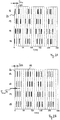
- Fig. 2A shows a CR stimulation in which repetitive sequences of stimuli 22 are generated in four stimulation channels 12 to 15.
- the stimuli 22 generated in the stimulation channels 12 to 15 are plotted against the time t.
- the sequences are generated in a predetermined time frame consisting of successive cycles.
- the individual cycles are in Fig. 2A delimited by dashed lines. Each cycle has the length T stim .
- each sequence consists of one in the present example Sequence of four time-shifted stimuli 22, which are generated in particular in each case different stimulation channels 12 to 15, wherein the time offset may relate in particular to the starting times of the stimuli 22.
- the order of the stimulation channels 12-15 in which the stimuli 22 are generated within the respective sequence is varied.
- a different filling of in Fig. 2A shown bars, which symbolize the stimuli 22, indicates a variation of the order.
- the stimuli 22 in the stimulation channels 12 to 15 in the first in Fig. 2A shown cycle in the order 15-12-14-13 produced. In the second cycle the order is 15-13-14-12 and in the third cycle the order is 12-15-14-13.
- exemplary stimulation form always applied in three consecutive cycles stimuli 22 and then a pause is taken for two cycles in which no stimuli 22 are generated. This pattern is repeated periodically.
- Fig. 2B shows a progression of CR stimulation of Fig. 2A
- the main difference to stimulation after Fig. 2A is that at the in Fig. 2B shown CR stimulation the sequences are only very slowly varied.
- the order of the stimulation channels 12 to 15, in which the stimuli 22 are generated within a sequence is kept constant for at least 20 sequentially generated sequences and only then varied.
- CR stimulation with such slowly varying sequences is opposite to that in Fig.
- sequences remain the same for at least 20 sequentially generated sequences and only be changed afterwards. It is further conceivable to increase the repetition of the same sequence and to keep the order of the stimulation channels 12 to 15 in which the stimuli 22 are generated within a sequence constant for at least 25 or at least 30 sequentially generated sequences. It should be noted at this point that in Fig. 2B for illustrative purposes, the sequences are already varied after less than 20 sequentially generated sequences. However, this is merely a simplified illustration of one compared to Fig. 2A to understand slow sequence variation.
- the variation of the sequences may, for. Stochastic or deterministic or mixed stochastic-deterministic.
- Fig. 2B Cycles are provided in which stimulation pauses are met.
- stimuli 22 may be generated during n consecutive cycles, and during the subsequent m cycles, no stimuli 22 designed to suppress the morbidly synchronous and oscillatory neural activity, where n and m are non-negative integers, may be generated.
- other stimuli which are not designed to suppress the pathologically synchronous and oscillatory neuronal activity, are applied in particular to the stimulation unit 11 during the stimulation pauses.
- the stimulation unit 11 during the stimulation pauses no stimuli generated.
- the pattern of n cycles of pacing and m cycles of no pacing may be periodically resumed.
- the cycles without stimulation are not counted, i. h.
- a variation of the sequence of the stimulation channels 12 to 15 takes place only when in each case a sequence of stimuli 22 was generated in i cycles.
- the number i, after each of which the sequence is varied, z. B. determined according to stochastic or deterministic or mixed stochastic-deterministic rules.
- variation of the sequences can be done with a constant rhythm, i. h., a variation, for example, always takes place after i cycles.
- each of the four stimulation channels 12 to 15 is a respective of in Fig. 1 shown subpopulations 32 to 34 of the diseased neuron population 31 stimulated.
- the stimulus 22 is applied periodically with the period T stim via each of the four stimulation channels 12 to 15.
- the stimuli 22 cause a phase reset of the neuronal activity of each stimulated subpopulation.
- the temporal delay between stimuli generated within a sequence in chronological succession and produced in different stimulation channels is 22 T stim / 4, since in the present exemplary embodiment the stimuli 22 are generated in four stimulation channels 12 to 15.
- the time delay between within a sequence would be temporally direct successive stimuli generated in different stimulation channels 22 T stim / P (this value can also be deviated by eg up to ⁇ 5%, ⁇ 10% or ⁇ 20%).
- the time delay T stim / P may refer to the beginning times of the stimuli 22.
- the stimuli 22 generated in different stimulation channels can be identical except for the different start times.
- the period T stim which indicates , on the one hand, the duration of one cycle and, on the other hand, the period of repetition of sequences that are the same, as well as the stimuli 22 generated in a respective stimulation channel 12 to 15, can be close to the mean period of the pathological oscillation of the neuron population 31 with the morbid synchronous and oscillatory neuronal activity or by up to ⁇ 5%, ⁇ 10% or ⁇ 20% from the mean period differ.
- the period of the pathological oscillation of the neuron population 31 to be stimulated can be measured, for example, by means of the measuring unit 16 described below, in particular by means of EEG. However, it is also possible to use for the period of pathological oscillation literary or empirical values that relate to the particular disease to be treated.
- the phase-recovering stimuli 22 can be, for example, individual stimuli or even composite stimuli.
- each stimulus 22 may consist of a pulse train with 1 to 100, in particular 2 to 10 individual pulses. Within a pulse train, the individual pulses are repeated without interruption at a frequency in the range of 50 to 500 Hz, in particular in the range of 100 to 150 Hz.
- it can be an acoustic, visual, tactile, vibratory (in particular vibrotactile), thermal, olfactory, gustatory, transcutaneous electrical, transcutaneous magnetic, transcranial electrical and / or transcranial magnetic pulse train and / or an ultrasonic pulse train act.
- stimuli 22 need not necessarily be generated in a stimulation in all L stimulation channels, for example, in only one selection of P of the L stimulation channels the stimuli 22 are generated (2 ⁇ P ⁇ L).
- P stimulation channels P! possible different sequences, wherein in each of these sequences exactly one stimulus 22 is generated in each of the P stimulation channels.
- all P! possible sequences for the stimulation to use or from the amount of P! possible sequences to select a subset for the stimulation. This subset may also vary in time according to stochastic or deterministic or mixed stochastic-deterministic rules.
- the sequence of sequences may be random or fixed prior to or even during stimulation.
- Fig. 1 illustrated device 1 for stimulating neurons with a morbidly synchronous and oscillatory neural activity performs a so-called "open loop" stimulation, ie, a stimulation without sensors, which are used to feedback and / or control of the stimulation.
- Fig. 3 schematically shows a device 2 for the stimulation of neurons with a morbid synchronous and oscillatory neuronal activity, with which a "closed loop" stimulation can be performed.
- the device 2 is a development of in Fig. 1 illustrated device 1 and Like the device 1, it contains a control unit 10 and a non-invasive stimulation unit 11 which have the same functions as the control and stimulation units 10, 11 of the device 1 described above.
- the device 2 comprises a measuring unit 16.
- the stimulation effect achieved by the stimuli 22 is monitored by means of the measuring unit 16.
- the measuring unit 16 receives one or more measurement signals 23 measured on the patient, optionally converts these into electrical signals 24 and supplies them to the control unit 10.
- the neuronal activity in the stimulated target area or in a region connected to the target area can be measured, wherein the neuronal activity of this area correlates sufficiently closely with the neuronal activity of the target area.
- the measuring unit 16 can also be a non-neuronal, z. As muscular activity or the activation of the autonomic nervous system, are measured, provided that they are sufficiently closely correlated with the neuronal activity of the target area.
- the measuring unit 16 contains one or more sensors, which in particular make it possible to detect a decrease or increase in the amplitude of the pathological oscillatory activity.
- sensors non-invasive sensors can be used, for. Chronic or intermittent electroencephalography (EEG) or electromyography (EMG) or magnetoencephalography (MEG) sensors.
- EEG electroencephalography
- EMG electromyography
- MEG magnetoencephalography
- Neuronal activity can also be detected by detecting characteristic patterns of movement, such as tremor, akinesia or epileptic seizures, with the aid of an accelerometer or gyroscope, or indirectly by measuring activation of the autonomic nervous system by measurement of the skin conductance are determined. It is also possible to find mood values that are recorded by the patient in portable devices, eg. As smartphones, can be used to control the stimulation success.
- the sensors may be implanted in the body of the patient.
- invasive sensors for example, epicortical electrodes, Tiefenhirnelektroden for the measurement of z.
- the control unit 10 processes the signals 24, z.
- the signals 24 may be amplified and / or filtered, and the processed signals 24 analyzed.
- the control unit 10 checks the stimulation success on the basis of the measurement signals 23 recorded in response to the application of the stimuli 22.
- the sequences generated by the stimulation unit 11 are varied with a constant rhythm, ie, the order of the stimulation channels 12 to 15 in which the stimuli 22 are generated per sequence is kept constant for a predetermined number of cycles (at least 20) and then the order is varied. Subsequently, the sequence for the given number of cycles is kept constant again and then varied.
- the rhythm with which the sequences are varied remains constant and, in particular, is not adapted to the measurement signals 23 processed by the control unit 10, but if necessary, other stimulation parameters, such as, for example, can be used.
- the amplitude of the stimuli 22, 23 are set in dependence on the measurement signals.
- the above configuration can be further developed by adjusting the rhythm of the sequences in response to the processed measurement signals 23.
- the control unit 10 checks the stimulation success based on the measurement signals 23 recorded in response to the application of the stimuli 22 and adjusts the stimulation parameters, in particular the rhythm with which the stimulation sequences are varied, as a function of the stimulation success.
- the stimulation success can be checked in particular by means of a threshold value comparison. Depending on which signals are used to determine the stimulation success, different threshold comparisons result. If z. B. the pathological neuronal synchronization via the sensors of the measuring unit 16, z. B. EEG electrodes, measured, is sufficient to reduce the synchronization by z. At least 20% compared to the situation without stimulation, to determine a sufficient stimulation success. According to one embodiment, an insufficient stimulation success can be determined if the diseased neuronal synchronization is not reduced by the application of the stimuli 22 by at least one predetermined value. If symptoms of the patient are used to determine stimulation success, it will depend on the type of related clinical parameters, which decrease is considered clinically relevant improvement. Such acceptance values (eg in the sense of the so-called minimal clinically perceptible improvement) are known to the person skilled in the art.
- the number of repetitions of the same sequence is prolonged. Is the stimulation whereas, according to the threshold criterion, the number of repetitions of the same sequence is shortened. In the simplest case, this can be a binary switching between two values of the number of repetitions of the same sequence: z. B. 25 repetitions on successful stimulation, whereas z. B. 100 repetitions in case of unsuccessful stimulation.
- the demand-controlled number of repetitions of the same sequence can also be varied / parameterized in smaller steps.
- the devices 1 and 2 can therefore also be understood as systems.
- the control unit 10 a processor, for.
- a microcontroller included.
- the stimulation methods described herein may be stored as software code in a memory associated with the control unit 10.
- Fig. 4 schematically shows a device 40 for non-invasive acoustic stimulation of neurons with a morbid synchronous and oscillatory neuronal activity according to an embodiment of the invention.
- Acoustic stimuli in particular acoustic CR stimuli, are administered to the patient via earphones or headphones 41 or differently configured loudspeakers, an earphone being a loudspeaker placed in the ear canal.
- the control signals used for this purpose are generated by a control unit 42.
- Non-invasively fixed EEG electrodes 43 which are connected via a cable 44, serve for "closed-loop" stimulation.
- the corresponding offsetting is in a small component 45, which preferably contains a measuring amplifier and is connected via cables 46, 47 with the EEG electrodes 43 and the earphones or headphones 41, and / or performed in the actual, the battery or the battery-accommodating control unit 42.
- the control unit 42 and the component 45 are in the in Fig. 4 illustrated embodiment interconnected telemetrically; In this case, component 45 (or a component connected to it via cable) also contains a battery.
- the control unit 42 and the component 45 may also be connected to one another via cables, so that the component 45 is fed by the control unit 42 via the power supply.
- Fig. 5 12 schematically shows a device 50 for the non-invasive visual stimulation of neurons with morbid synchronous and oscillatory neuronal activity according to an embodiment of the invention.
- the patient wears a stimulation goggles 51, the z. B. is attached via bracket 52 on the head of the patient.
- a component 53 contains a clearing and telemetry unit. The latter is used to connect to the actual, the battery or the battery-harboring control unit 54.
- the component 53 and the control unit 54 are connected to each other telemetrically; In this case, component 53 (or a component connected to it via cable) also contains a battery. Alternatively, the component 53 and the control unit 54 may also be connected to one another via cables.
- Non-invasively fixed EEG electrodes 55 are used for closed-loop stimulation.
- the EEG electrodes 55 are connected to the component 53 via cables 56, 57.
- the visual stimuli generated by the stimulation goggles 51 can be based on a luminosity variation or variation of the light intensity or intensity, for example, they can be applied as pulses or as sequences of pulses with varied luminosity or brightness.
- the visual stimuli can, depending on the design as luminance modulation of natural visual stimuli, z. B. by means of a homogeneous or segmented transmission goggles, in which the transmission can be controlled voltage-dependent, in addition to a natural visual stimulus occurring, modulated visual stimulus, z. B. by means of a partially transparent light glasses, or as an artificial visual brightness stimulus, z. B. by means of an opaque light glasses, administered.
- the stimulation goggles 51 are preferably subdivided into different segments whose luminous intensity or transmission or brightness can be controlled separately in order to be able to stimulate different points of the retina independently of one another.
- Fig. 6 12 schematically illustrates an apparatus 60 for non-invasive tactile, vibratory, thermal, transcutaneous, electrical and / or transcutaneous magnetic stimulation and / or ultrasound stimulation of neurons having morbidly synchronous and oscillatory neural activity in accordance with an embodiment of the invention.
- the device 60 comprises a stimulation unit 61, a control unit 62 controlling the stimulation unit 61 and an accelerometer 63 for recording measurement signals.
- the stimulation unit 61 and the accelerometer 63 may be connected to the control unit 62 telemetrically or by cable.
- the stimulation unit 61 comprises a plurality of stimulation elements for producing tactile, vibratory, thermal, transcutaneous electrical and / or transcutaneous magnetic stimuli and / or ultrasound stimuli.
- the stimulation elements are designed such that they can be placed on the skin of the patient. Depending on the disease or affected parts of the body, the stimulation elements are fastened in a suitable arrangement on the skin of the patient, for example on the arm, on the leg, on the hand and / or on the foot of the patient.
- the plurality of stimulation elements makes it possible to stimulate different receptive areas of the skin over the individual stimulation elements coordinated temporally and spatially.
- Stimulation elements for producing tactile and / or vibratory stimuli are, for example, vibration actuators which impress with a frequency in the range of 1 to 300 Hz and in particular 1 to 60 Hz and preferably 100 to 300 Hz into the skin of the patient and thereby generate the desired stimuli.
- Stimulation elements for generating thermal stimuli can be, for example, lasers or differently configured elements for generating heat, in particular heat radiation.
- Electrodes are typically affixed to the patient's skin to produce transcutaneous electrical stimuli.
- Transcutaneous magnetic stimuli can be generated by appropriate stimulation elements for generating magnetic stimuli, in particular current-carrying coils.
- Ultrasonic stimuli are generated by stimulation elements to generate ultrasonic waves.
- the tactile, vibratory, thermal, transcutaneous electrical and / or transcutaneous magnetic stimuli and / or ultrasonic stimuli may be picked up by in or under the skin receptors and transmitted to the nervous system.
- These receptors include, for example, Merkel cells, Ruffini bodies, Meissner bodies, and hair follicle receptors which act, in particular, as receptors for the tactile stimuli.
- the vibratory stimuli are aimed primarily at the depth sensitivity.
- the vibratory stimuli can be absorbed by receptors located in the skin, muscles, subcutaneous tissue, and / or tendons of the patient.
- thermoreceptors As receptors for the vibratory stimuli are exemplary the father Pacini corpuscles called, which convey vibration sensations and accelerations.
- the thermal stimuli are absorbed by the thermoreceptors of the skin. These are warm receptors (also called heat receptors, warm sensors or heat sensors) and cold sensors (also called cold sensors, cold receptors or cold receptors). In the human skin, the cold sensors are more superficial, the warm receptors a little deeper.
- the transcutaneous electrical and transcutaneous magnetic stimuli as well as the ultrasonic stimuli do not specifically affect only one group of receptors located in or under the skin and, moreover, can also directly irritate nerve fibers.
- the targeted stimulation of certain areas of the brain or spinal cord is made possible by the tonotopic or somatotopic assignment of body regions to these areas.
- acoustic stimuli in the inner ear are converted into nerve impulses and transmitted via the auditory nerve to the auditory cortex.
- the tonotopic arrangement of the auditory cortex activates a specific part of the auditory cortex during the acoustic stimulation of the inner ear at a specific frequency.
- the stimulation elements may be attached to, for example, the foot, lower leg and thigh, or the patient's hand, forearm and upper arm to thereby stimulate certain neurons.
- each stimulation channel is assigned to a respective different frequency range from which the tones which are applied as acoustic stimuli in the respective stimulation channel are selected.
- the pacing channels are determined by different locations or areas in the patient's field of view.
- the visual stimuli generated in a respective stimulation channel are generated at a respective location or in a respective area of the visual field.
- the stimulation channels of the tactile, vibratory, thermal, transcutaneous electrical and / or transcutaneous magnetic stimuli and / or Ultrasonic stimuli are determined by the areas of the skin that are stimulated with the respective stimulation elements. Consequently, each stimulation channel is associated with a respective site or area of the skin.
- the stimulation channels of the gustatory stimuli are determined by the locations of the tongue, which are stimulated with the corresponding taste qualities or electrical stimuli.
- psychophysically sufficient disjoint odor stimuli are used, by means of which the stimulation channels are determined.
- the psychophysically sufficiently disjoint odor stimuli could, for. B. personalized, d. H. adapted to the individual patient.
- electrodes or magnetic field generators in particular current-carrying coils, are fastened to the body, in particular to the head, of the patient.
- currents or magnetic fields in the brain and / or spinal cord of the patient can be generated.
- different target areas in the brain and / or spinal cord can be stimulated.
- the stimulation channels are thus determined by the locations on the body of the patient to which the electrodes or magnetic field generators are attached.
- the stimulation unit described above can therefore separately stimulate different areas of the brain or spinal cord via different stimulation channels by the applied stimuli via nerve leads to different target areas, which are located in the brain and / or spinal cord, forwarded.
- the target areas may be during stimulation with possibly different and / or time-delayed stimuli are stimulated.
- the stimuli 22 cause a so-called reset, the phase of neuronal activity of the stimulated neurons.
- the phase reset of the individual stimuli 22 can be checked with the aid of the measuring signals 23 recorded by the measuring unit 16. Such an examination can be made before the actual therapeutic neurostimulation.
- a signal is measured by means of a sensor of the measuring unit 16, which signal sufficiently represents the activity of the subpopulation stimulated via the j-th stimulation channel.
- This signal is obtained either directly from the subpopulation via a non-invasive measurement, e.g. B. via EEG or MEG electrodes, or an invasive measurement, eg. B. via implanted electrodes, as a surface EEG or as a local field potential via depth electrodes.
- the signal can also be determined indirectly by measuring a quantity correlated with the activity of the stimulated subpopulation.
- neuronal signals typically contain rhythmic activity in different frequency bands, it is advantageous in such cases, e.g. B. by bandpass filtering or wavelet analysis or empirical mode decomposition signal x j (t), which represents the pathological oscillatory activity of the j-th stimulation channel stimulated subpopulation to determine.
- a little effort to check for a phase reset is to determine the mean response.
- a stimulus with identical stimulus parameters is applied at the times ⁇ 1 , ⁇ 2 ,..., ⁇ 1.
- the distances between the individual stimuli ⁇ k + 1 - ⁇ k should be sufficiently large and randomized, ie not constant, in order to avoid transient phenomena (cf. PA Tass: Transmission of stimulus-locked responses in two-coupled phase oscillators. Phys. Rev. E 69, 051909-1-24 (2004 )).
- the distances ⁇ k + 1 - ⁇ k should be in the range of at least ten times, better than one hundred times, the mean period of the pathological oscillation.
- z Eg the 99th percentile of the pre-stimulus distribution from
- the phase ⁇ j ( t ) of x j ( t ) is determined.
- This is done by means of Hilbert transformation from the signal determined by bandpass filtering or empirical mode decomposition, which represents the pathological oscillatory activity.
- the empirical mode decomposition allows a parameter-independent determination of physiologically relevant modes in different frequency ranges compared to band-pass filtering (cf. NE Huang et al .: The empirical mode decomposition and the Hilbert spectrum for nonlinear and non-stationary time series analysis. Proc. R. Soc. A: Math. Phys. Closely. Sci. 454: 903-995 (1998 )).
- the combination of empirical mode decomposition with subsequent Hilbert transformation is called the Hilbert-Huang transformation (cf.
- phase ⁇ j ( t ) can also be determined by means of wavelet analysis.
- the person skilled in various methods are known, with which it can be demonstrated that a distribution has a clustering value (ie a peak).
- 1 l ⁇ k 1 l exp i ⁇ j ⁇ k + t
- a phase reset occurs when p (t) z. B. exceeds the maximum or the 99th percentile of the pre-stimulus distribution of p (t) (at a time or within a small time window of, for example, 20 ms width).
- the effects achievable with the invention described herein are illustrated by simulation results.
- the simulation is based on a network of 200 neurons, with all neurons exhibiting a strong stimulating short-range coupling and a weak inhibitory long-range coupling.
- the synaptic coupling strengths in the network may change in accordance with STDP (Spike Timing Dependent Plasticity) rules.
- STDP Spike Timing Dependent Plasticity
- the simulation is based on the following boundary conditions.
- the synchronization degree S can be in the range of 0 (for a complete desynchronization) to 1 (for a complete phase synchronization).
- Figs. 7A and 7B is the degree of synchronization S of the simulated neuron population with a morbid synchronous and oscillatory neuronal activity before, during and after CR stimulation shown.
- the horizontal bars on the top of the two graphs indicate the period during which CR pacing is applied.
- the sequences were varied at the beginning of each cycle, while the sequences at the in Fig. 7B simulation were varied after every 100 cycles.
- the degree of synchronization S was calculated after every millisecond.
- the 50th percentile of the values for the degree of synchronization S for three different stimulation strengths K is shown.
- Figs. 7A and 7B see that except for the CR stimulation with a stimulation intensity K of 0.10 the in Fig. 7B shown slowly varying CR stimulation shows a greater and longer-lasting stimulation success.
- the sequence of the sequences and the initial conditions of the network have an influence on the stimulation success. This is in the 8A to 8D shown in which the degree of synchronization S is plotted against the stimulation intensity K.
- the in the Figs. 8A and 8C The simulations shown are based on a variation of the sequences in each cycle, whereas those in the FIGS. 8B and 8D simulations shown, the sequences were varied only after 100 cycles.
- the 50th percentile of the values for the degree of synchronization S for the last 16 seconds of the stimulation is shown as a function of the stimulation intensity K for two different sequences of the sequences.
- the solid lines show the simulation results for the same order of the sequences as they are for the simulations of Figs. 7A and 7B while the dotted lines represent the simulation results in a different order.
- the Figs. 8A and 8B show that slowly varying CR stimulation is more robust to the sequence of sequences compared to rapidly varying CR stimulation.
- the simulations also show that the initial conditions of the network also influence the desynchronization of the neuronal activity.
- the 50th percentile of the values for the degree of synchronization S for the last 16 seconds of the stimulation is represented as a function of the stimulation intensity K for two different initial conditions of the network.
- the solid lines show the simulation results for the same initial conditions of the network as they were for the simulations of Figs. 7A and 7B while the dotted lines represent the simulation results for other initial conditions of the network.
- the slowly varying CR stimulation is more robust the initial conditions of the network compared to rapidly varying CR stimulation.
- Figs. 9A and 9B show the 50th percentile of the values for the degree of synchronization S for the last 16 seconds of the stimulation as a function of the stimulation intensity K for different sequences of the sequences and different initial conditions of the network.
- the median of the results for each value of the stimulation intensity K is in each case connected by a line.
- Fig. 9A shows the results of rapidly varying CR stimulation
- Fig. 9B shows the results of slowly varying CR stimulation.
- the Figs. 9A and 9B see that the slowly varying CR stimulation desynchronizes the highly synchronous neuronal network stronger and more robustly than is possible with rapidly varying CR stimulation.
Landscapes
- Health & Medical Sciences (AREA)
- Life Sciences & Earth Sciences (AREA)
- Neurology (AREA)
- General Health & Medical Sciences (AREA)
- Biomedical Technology (AREA)
- Engineering & Computer Science (AREA)
- Animal Behavior & Ethology (AREA)
- Public Health (AREA)
- Veterinary Medicine (AREA)
- Neurosurgery (AREA)
- Heart & Thoracic Surgery (AREA)
- Biophysics (AREA)
- Physics & Mathematics (AREA)
- Medical Informatics (AREA)
- Molecular Biology (AREA)
- Pathology (AREA)
- Surgery (AREA)
- Radiology & Medical Imaging (AREA)
- Nuclear Medicine, Radiotherapy & Molecular Imaging (AREA)
- Physiology (AREA)
- Psychology (AREA)
- Developmental Disabilities (AREA)
- Acoustics & Sound (AREA)
- Hematology (AREA)
- Anesthesiology (AREA)
- Social Psychology (AREA)
- Psychiatry (AREA)
- Hospice & Palliative Care (AREA)
- Child & Adolescent Psychology (AREA)
- Electrotherapy Devices (AREA)
- Magnetic Treatment Devices (AREA)
Claims (14)
- Dispositif (1 ; 2) pour stimuler des neurones (31) comprenant- une unité de stimulation non-invasive (11) pour générer des stimuli (22) dans une pluralité de canaux de stimulation (12-15), sachant que l'unité de stimulation (11) est conçue de manière que les stimuli (22) stimulent une population de neurones (31) dans le cerveau et/ou dans la moelle épinière (30) d'un patient à différents emplacements respectifs via les canaux de stimulation (12-15), et- une unité de commande (10) qui commande l'unité de stimulation (11) de telle manière que l'unité de stimulation (11) produise des séquences répétitives de stimuli (22), sachant que- l'ordre des canaux de stimulation (12-15) dans lesquels les stimuli (22) sont générés à l'intérieur d'une séquence est constant pour au moins 20 séquences générées successivement, et qu'il est ensuite varié.
- Dispositif (1 ; 2) d'après la revendication 1, sachant que les stimuli (22) sont des stimuli acoustiques, visuels, tactiles, vibratoires, thermiques, olfactifs, gustatifs, transcutanés électriques, transcutanés magnétiques, transcrâniens électriques et/ou transcrâniens magnétiques et/ou ultrasoniques.
- Dispositif (1 ; 2) d'après la revendication 1 ou 2, sachant que les séquences sont générées dans une grille de temps constituée de cycles successifs et qu'au moins dans certains des cycles est générée respectivement une séquence de stimuli (22).
- Dispositif (1 ; 2) d'après la revendication 3, sachant que, dans un cycle respectif, soit exactement une séquence de stimuli (22) est générée, soit aucun stimuli n'est généré.
- Dispositif (1 ; 2) d'après la revendication 3 ou 4, sachant que des stimuli (22) sont générés pendant n cycles consécutifs et aucun stimulus n'est généré pendant les m cycles suivants et que ce modèle est poursuivi périodiquement, sachant que n et m sont des nombres entiers non négatifs.
- Dispositif (1 ; 2) d'après une quelconque des revendications précédentes, sachant que le modèle, d'après lequel la séquence de canaux de stimulation (12-15), dans laquelle les stimuli (22) sont générés à l'intérieur d'une séquence, est constante pendant au moins 20 séquences générées successivement et est ensuite modifiée, est répété plusieurs fois.
- Dispositif (1 ; 2) d'après une quelconque des revendications précédentes, sachant que stimuli (22) sont conçus pour supprimer l'activité pathologiquement synchrone et oscillatoire de la population de neurones (31) lorsqu'ils sont administrés au patient par l'intermédiaire de la pluralité de canaux de stimulation (12-15).
- Dispositif (1 ; 2) d'après la revendication 7, sachant que la durée d'un cycle correspond essentiellement à la période moyenne de l'oscillation pathologique des neurones (31).
- Dispositif (1 ; 2) d'après une quelconque des revendications précédentes, sachant que l'unité de stimulation (11) est conçue de telle manière que les stimuli (22) générés dans un canal de stimulation (12-15) respectif stimulent une sous-population (32-35) respective de la population neuronale (31) et réinitialisent la phase de l'activité neuronale de cette sous-population (32-35).
- Dispositif (1 ; 2) d'après une quelconque des revendications précédentes, sachant que l'unité de stimulation (11) génère à l'intérieur d'une séquence respective exactement un stimulus (22) dans chaque canal de stimulation (11-15).
- Dispositif (1 ; 2) d'après la revendication 10, sachant que exactement un stimulus (22) est exactement un train d'impulsions.
- Dispositif (2) d'après une quelconque des revendications précédentes, comprenant une unité de mesure (16) pour recevoir ou encore enregistrer des signaux de mesure (23) représentant une activité neuronale de la population de neurones (31) stimulée par les stimuli (22).
- Dispositif (2) d'après la revendication 12, sachant que l'unité de commande (10) est conçue de telle manière qu'elle étend le nombre de séquences générées successivement dans lesquelles la séquence de canaux de stimulation (12-15), dans laquelle les stimuli (22) sont générés dans une séquence, est constante, lorsque ladite unité de commande (10) détermine à partir des signaux de mesure (23) qu'un degré de synchronisation de la population de neurones stimulée (31) n'est pas réduit d'au moins une valeur seuil prédéterminée par l'application des stimuli (22).
- Programme informatique consistant en un code logiciel conçu pour amener un dispositif d'après la revendication 1 à- générer des signaux de commande pour la commande d'une unité de stimulation non-invasive (11), sachant que l'unité de stimulation (11) génère des stimuli (22) dans une pluralité de canaux de stimulation (12-15) et que les stimuli (22) stimulent une population de neurones (31) dans le cerveau et/ou dans la moelle épinière (30) d'un patient via les canaux de stimulation (12-15) à différents emplacements respectifs, les signaux de commande entraînant l'unité de stimulation (11) de manière que- l'unité de stimulation (11) génère de manière répétitive des séquences de stimuli (22), et que- l'ordre des canaux de stimulation (12-15), dans lesquels les stimuli (22) sont générés à l'intérieur d'une séquence, est constant pour au moins 20 séquences générées successivement et qu'il est ensuite varié.
Applications Claiming Priority (2)
| Application Number | Priority Date | Filing Date | Title |
|---|---|---|---|
| DE102014117427.5A DE102014117427B4 (de) | 2014-11-27 | 2014-11-27 | Vorrichtung zur effektiven nicht-invasiven Neurostimulation mittels variierender Reizsequenzen |
| PCT/EP2015/077802 WO2016083520A1 (fr) | 2014-11-27 | 2015-11-26 | Dispositif et procédé de neurostimulation non-invasive efficace à l'aide de séquences d'excitation variables |
Publications (2)
| Publication Number | Publication Date |
|---|---|
| EP3183033A1 EP3183033A1 (fr) | 2017-06-28 |
| EP3183033B1 true EP3183033B1 (fr) | 2018-08-29 |
Family
ID=54705179
Family Applications (1)
| Application Number | Title | Priority Date | Filing Date |
|---|---|---|---|
| EP15801158.5A Active EP3183033B1 (fr) | 2014-11-27 | 2015-11-26 | Dispositif de neurostimulation non-invasive efficace à l'aide de séquences d'excitation variables |
Country Status (5)
| Country | Link |
|---|---|
| US (1) | US10350410B2 (fr) |
| EP (1) | EP3183033B1 (fr) |
| JP (1) | JP6717824B2 (fr) |
| DE (2) | DE102014117427B4 (fr) |
| WO (1) | WO2016083520A1 (fr) |
Families Citing this family (17)
| Publication number | Priority date | Publication date | Assignee | Title |
|---|---|---|---|---|
| US20170325718A1 (en) * | 2016-05-12 | 2017-11-16 | Bragi GmbH | Neuropathic Diagnosis and Monitoring Using Earpiece Device, System, and Method |
| CA3030424A1 (fr) * | 2016-07-13 | 2018-01-18 | GSK Consumer Healthcare S.A. | Appareil et procede de compensation automatisee de stimulation nerveuse electrique transcutanee pour des fluctuations temporelles telles que les rythmes circadiens |
| US20210401664A1 (en) * | 2017-07-28 | 2021-12-30 | The Board Of Trustees Of The Leland Stanford Junior University | Safe and efficient vibrotactile multi-channel stimulation for the treatment of brain disorders |
| WO2019133997A1 (fr) * | 2017-12-31 | 2019-07-04 | Neuroenhancement Lab, LLC | Système et procédé de neuro-activation pour améliorer la réponse émotionnelle |
| DE102018104515B4 (de) * | 2018-02-28 | 2021-12-09 | Prof. Dr. Fischer AG | Vorrichtung zur transkraniellen Magnetstimulation |
| CN112533663A (zh) * | 2018-06-22 | 2021-03-19 | 格瑞塔股份公司 | 用于刺激患者的神经元以抑制其病理性同步活动的医疗设备和方法 |
| EP3846895A1 (fr) * | 2018-09-03 | 2021-07-14 | Gretap AG | Dispositif et procédé de traitement médical pour stimuler les neurones d'un patient afin de supprimer une activité pathologiquement synchrone des neurones |
| TWI677321B (zh) * | 2018-09-07 | 2019-11-21 | 陳韋達 | 用於頭痛疾患的大腦皮質興奮與抑制能力量測系統 |
| US11701293B2 (en) | 2018-09-11 | 2023-07-18 | Encora, Inc. | Apparatus and method for reduction of neurological movement disorder symptoms using wearable device |
| US11839583B1 (en) | 2018-09-11 | 2023-12-12 | Encora, Inc. | Apparatus and method for reduction of neurological movement disorder symptoms using wearable device |
| WO2020185734A1 (fr) * | 2019-03-11 | 2020-09-17 | Regents Of The University Of Minnesota | Systèmes et procédés pour une stimulation combinée ultrasonore et électrique pour traiter un sujet |
| RU194111U1 (ru) * | 2019-04-26 | 2019-11-28 | Общество с ограниченной ответственностью "Альматек" | Устройство управления устройством предъявления электрических импульсов при транслингвальной нейростимуляции |
| RU194115U1 (ru) * | 2019-04-26 | 2019-11-28 | Акционерное общество "ПК Альматек" | Устройство для предъявления электрических импульсов при транслингвальной нейростимуляции |
| US11413425B2 (en) | 2019-05-24 | 2022-08-16 | Neuroenhancement Lab, LLC | Device, system, and method for reducing coronasomnia to enhance immunity and immune response |
| CN110815181B (zh) * | 2019-11-04 | 2021-04-20 | 西安交通大学 | 人体下肢运动意图脑肌融合感知的多层次校准系统及方法 |
| EP3838334A1 (fr) * | 2019-12-18 | 2021-06-23 | ONWARD Medical B.V. | Système de fourniture de stimulation |
| US11896852B2 (en) | 2020-12-21 | 2024-02-13 | Xerox Corporation | Closed-loop non-invasive transcranial stimulation and neural activity recording system and method |
Family Cites Families (10)
| Publication number | Priority date | Publication date | Assignee | Title |
|---|---|---|---|---|
| DE10233960B4 (de) * | 2002-07-29 | 2006-11-02 | Forschungszentrum Jülich GmbH | Vorrichtung zur bedarfsgesteuerten Modulation physiologischer und pathologischer neuronaler rhythmischer Aktivität im Gehirn mittels sensorischer Stimulation |
| DE102004025945A1 (de) * | 2004-05-27 | 2005-12-29 | Forschungszentrum Jülich GmbH | Verfahren und Vorrichtung zur Entkopplung und/oder Desynchronisation neuronaler Hirnaktivität |
| JP4945644B2 (ja) * | 2006-12-22 | 2012-06-06 | エーベーエス テヒノロギーズ ゲーエムベーハー | ヒトの脳を刺激する装置 |
| DE102008015259B4 (de) * | 2008-03-20 | 2010-07-22 | Anm Adaptive Neuromodulation Gmbh | Vorrichtung und Verfahren zur auditorischen Stimulation |
| DE102009015723B4 (de) | 2009-03-31 | 2013-12-19 | Forschungszentrum Jülich GmbH | Stimulationselektrode |
| DE102010000390A1 (de) * | 2010-02-11 | 2011-08-11 | Forschungszentrum Jülich GmbH, 52428 | Vorrichtung und Verfahren zur Behandlung eines Patienten mit Vibrations-, Tast- und/oder Thermoreizen |
| DE102010016404A1 (de) * | 2010-04-12 | 2012-12-27 | Forschungszentrum Jülich GmbH | Vorrichtung und Verfahren zur konditionierten desynchronisierenden nicht-invasiven Stimulation |
| US9878161B2 (en) * | 2011-04-29 | 2018-01-30 | Medtronic, Inc. | Entrainment of bioelectrical brain signals |
| DE102012002436B4 (de) | 2012-02-08 | 2014-08-21 | Forschungszentrum Jülich GmbH | Vorrichtung zur Eichung einer nicht-invasiven desynchronisierenden Neurostimulation |
| DE102012005030B4 (de) * | 2012-03-12 | 2016-06-16 | Forschungszentrum Jülich GmbH | Vorrichtung und Verfahren zur Stimulation mit Thermoreizen |
-
2014
- 2014-11-27 DE DE102014117427.5A patent/DE102014117427B4/de not_active Expired - Fee Related
-
2015
- 2015-11-26 DE DE112015003833.7T patent/DE112015003833A5/de not_active Withdrawn
- 2015-11-26 EP EP15801158.5A patent/EP3183033B1/fr active Active
- 2015-11-26 JP JP2017527905A patent/JP6717824B2/ja active Active
- 2015-11-26 WO PCT/EP2015/077802 patent/WO2016083520A1/fr active Application Filing
- 2015-11-26 US US15/528,157 patent/US10350410B2/en active Active
Also Published As
| Publication number | Publication date |
|---|---|
| JP6717824B2 (ja) | 2020-07-08 |
| DE102014117427B4 (de) | 2016-12-15 |
| US20170368342A1 (en) | 2017-12-28 |
| DE102014117427A1 (de) | 2016-06-02 |
| WO2016083520A1 (fr) | 2016-06-02 |
| EP3183033A1 (fr) | 2017-06-28 |
| JP2017535364A (ja) | 2017-11-30 |
| US10350410B2 (en) | 2019-07-16 |
| DE112015003833A5 (de) | 2017-09-07 |
Similar Documents
| Publication | Publication Date | Title |
|---|---|---|
| EP3183033B1 (fr) | Dispositif de neurostimulation non-invasive efficace à l'aide de séquences d'excitation variables | |
| EP3310432B1 (fr) | Dispositif pour neurostimulation efficace non invasive en deux étapes | |
| EP2797667B1 (fr) | Dispositif d'étalonnage d'une neurostimulation désynchronisante non effractive | |
| EP2826448B1 (fr) | Dispositif de stimulation auditive | |
| EP2358430B1 (fr) | Dispositif de stimulation conditionnelle de desynchronisation | |
| EP3188794B1 (fr) | Dispositif de neurostimulation non effractive au moyen de rafales multicanaux | |
| DE102012002437B4 (de) | Vorrichtung zur Eichung einer invasiven, elektrischen und desynchronisierenden Neurostimulation | |
| EP3397336B1 (fr) | Dispositif pour la neurostimulation neurologique invasive efficace à plusieurs segments | |
| EP3183031B1 (fr) | Dispositif de neurostimulation désynchronisante efficace non invasive | |
| EP3285854B1 (fr) | Dispositif de stimulation neurologique invasive efficace à deux niveaux | |
| EP3183032B1 (fr) | Dispositif de neurostimulation invasive efficace à l'aide de séquences d'excitation variables |
Legal Events
| Date | Code | Title | Description |
|---|---|---|---|
| PUAI | Public reference made under article 153(3) epc to a published international application that has entered the european phase |
Free format text: ORIGINAL CODE: 0009012 |
|
| 17P | Request for examination filed |
Effective date: 20170321 |
|
| AK | Designated contracting states |
Kind code of ref document: A1 Designated state(s): AL AT BE BG CH CY CZ DE DK EE ES FI FR GB GR HR HU IE IS IT LI LT LU LV MC MK MT NL NO PL PT RO RS SE SI SK SM TR |
|
| AX | Request for extension of the european patent |
Extension state: BA ME |
|
| RIN1 | Information on inventor provided before grant (corrected) |
Inventor name: ZEITLER, MAGTELD Inventor name: TASS, PETER ALEXANDER |
|
| DAV | Request for validation of the european patent (deleted) | ||
| DAX | Request for extension of the european patent (deleted) | ||
| GRAP | Despatch of communication of intention to grant a patent |
Free format text: ORIGINAL CODE: EPIDOSNIGR1 |
|
| INTG | Intention to grant announced |
Effective date: 20180215 |
|
| GRAJ | Information related to disapproval of communication of intention to grant by the applicant or resumption of examination proceedings by the epo deleted |
Free format text: ORIGINAL CODE: EPIDOSDIGR1 |
|
| GRAR | Information related to intention to grant a patent recorded |
Free format text: ORIGINAL CODE: EPIDOSNIGR71 |
|
| GRAS | Grant fee paid |
Free format text: ORIGINAL CODE: EPIDOSNIGR3 |
|
| INTC | Intention to grant announced (deleted) | ||
| GRAA | (expected) grant |
Free format text: ORIGINAL CODE: 0009210 |
|
| INTG | Intention to grant announced |
Effective date: 20180712 |
|
| AK | Designated contracting states |
Kind code of ref document: B1 Designated state(s): AL AT BE BG CH CY CZ DE DK EE ES FI FR GB GR HR HU IE IS IT LI LT LU LV MC MK MT NL NO PL PT RO RS SE SI SK SM TR |
|
| REG | Reference to a national code |
Ref country code: GB Ref legal event code: FG4D Free format text: NOT ENGLISH |
|
| REG | Reference to a national code |
Ref country code: CH Ref legal event code: EP |
|
| REG | Reference to a national code |
Ref country code: AT Ref legal event code: REF Ref document number: 1034425 Country of ref document: AT Kind code of ref document: T Effective date: 20180915 |
|
| REG | Reference to a national code |
Ref country code: IE Ref legal event code: FG4D Free format text: LANGUAGE OF EP DOCUMENT: GERMAN |
|
| REG | Reference to a national code |
Ref country code: DE Ref legal event code: R096 Ref document number: 502015005742 Country of ref document: DE |
|
| REG | Reference to a national code |
Ref country code: FR Ref legal event code: PLFP Year of fee payment: 4 |
|
| REG | Reference to a national code |
Ref country code: NL Ref legal event code: MP Effective date: 20180829 |
|
| REG | Reference to a national code |
Ref country code: LT Ref legal event code: MG4D |
|
| PG25 | Lapsed in a contracting state [announced via postgrant information from national office to epo] |
Ref country code: GR Free format text: LAPSE BECAUSE OF FAILURE TO SUBMIT A TRANSLATION OF THE DESCRIPTION OR TO PAY THE FEE WITHIN THE PRESCRIBED TIME-LIMIT Effective date: 20181130 Ref country code: FI Free format text: LAPSE BECAUSE OF FAILURE TO SUBMIT A TRANSLATION OF THE DESCRIPTION OR TO PAY THE FEE WITHIN THE PRESCRIBED TIME-LIMIT Effective date: 20180829 Ref country code: RS Free format text: LAPSE BECAUSE OF FAILURE TO SUBMIT A TRANSLATION OF THE DESCRIPTION OR TO PAY THE FEE WITHIN THE PRESCRIBED TIME-LIMIT Effective date: 20180829 Ref country code: SE Free format text: LAPSE BECAUSE OF FAILURE TO SUBMIT A TRANSLATION OF THE DESCRIPTION OR TO PAY THE FEE WITHIN THE PRESCRIBED TIME-LIMIT Effective date: 20180829 Ref country code: NO Free format text: LAPSE BECAUSE OF FAILURE TO SUBMIT A TRANSLATION OF THE DESCRIPTION OR TO PAY THE FEE WITHIN THE PRESCRIBED TIME-LIMIT Effective date: 20181129 Ref country code: NL Free format text: LAPSE BECAUSE OF FAILURE TO SUBMIT A TRANSLATION OF THE DESCRIPTION OR TO PAY THE FEE WITHIN THE PRESCRIBED TIME-LIMIT Effective date: 20180829 Ref country code: IS Free format text: LAPSE BECAUSE OF FAILURE TO SUBMIT A TRANSLATION OF THE DESCRIPTION OR TO PAY THE FEE WITHIN THE PRESCRIBED TIME-LIMIT Effective date: 20181229 Ref country code: LT Free format text: LAPSE BECAUSE OF FAILURE TO SUBMIT A TRANSLATION OF THE DESCRIPTION OR TO PAY THE FEE WITHIN THE PRESCRIBED TIME-LIMIT Effective date: 20180829 Ref country code: BG Free format text: LAPSE BECAUSE OF FAILURE TO SUBMIT A TRANSLATION OF THE DESCRIPTION OR TO PAY THE FEE WITHIN THE PRESCRIBED TIME-LIMIT Effective date: 20181129 |
|
| PG25 | Lapsed in a contracting state [announced via postgrant information from national office to epo] |
Ref country code: LV Free format text: LAPSE BECAUSE OF FAILURE TO SUBMIT A TRANSLATION OF THE DESCRIPTION OR TO PAY THE FEE WITHIN THE PRESCRIBED TIME-LIMIT Effective date: 20180829 Ref country code: HR Free format text: LAPSE BECAUSE OF FAILURE TO SUBMIT A TRANSLATION OF THE DESCRIPTION OR TO PAY THE FEE WITHIN THE PRESCRIBED TIME-LIMIT Effective date: 20180829 Ref country code: AL Free format text: LAPSE BECAUSE OF FAILURE TO SUBMIT A TRANSLATION OF THE DESCRIPTION OR TO PAY THE FEE WITHIN THE PRESCRIBED TIME-LIMIT Effective date: 20180829 |
|
| PG25 | Lapsed in a contracting state [announced via postgrant information from national office to epo] |
Ref country code: IT Free format text: LAPSE BECAUSE OF FAILURE TO SUBMIT A TRANSLATION OF THE DESCRIPTION OR TO PAY THE FEE WITHIN THE PRESCRIBED TIME-LIMIT Effective date: 20180829 Ref country code: CZ Free format text: LAPSE BECAUSE OF FAILURE TO SUBMIT A TRANSLATION OF THE DESCRIPTION OR TO PAY THE FEE WITHIN THE PRESCRIBED TIME-LIMIT Effective date: 20180829 Ref country code: ES Free format text: LAPSE BECAUSE OF FAILURE TO SUBMIT A TRANSLATION OF THE DESCRIPTION OR TO PAY THE FEE WITHIN THE PRESCRIBED TIME-LIMIT Effective date: 20180829 Ref country code: RO Free format text: LAPSE BECAUSE OF FAILURE TO SUBMIT A TRANSLATION OF THE DESCRIPTION OR TO PAY THE FEE WITHIN THE PRESCRIBED TIME-LIMIT Effective date: 20180829 Ref country code: EE Free format text: LAPSE BECAUSE OF FAILURE TO SUBMIT A TRANSLATION OF THE DESCRIPTION OR TO PAY THE FEE WITHIN THE PRESCRIBED TIME-LIMIT Effective date: 20180829 Ref country code: PL Free format text: LAPSE BECAUSE OF FAILURE TO SUBMIT A TRANSLATION OF THE DESCRIPTION OR TO PAY THE FEE WITHIN THE PRESCRIBED TIME-LIMIT Effective date: 20180829 |
|
| PG25 | Lapsed in a contracting state [announced via postgrant information from national office to epo] |
Ref country code: DK Free format text: LAPSE BECAUSE OF FAILURE TO SUBMIT A TRANSLATION OF THE DESCRIPTION OR TO PAY THE FEE WITHIN THE PRESCRIBED TIME-LIMIT Effective date: 20180829 Ref country code: SK Free format text: LAPSE BECAUSE OF FAILURE TO SUBMIT A TRANSLATION OF THE DESCRIPTION OR TO PAY THE FEE WITHIN THE PRESCRIBED TIME-LIMIT Effective date: 20180829 Ref country code: SM Free format text: LAPSE BECAUSE OF FAILURE TO SUBMIT A TRANSLATION OF THE DESCRIPTION OR TO PAY THE FEE WITHIN THE PRESCRIBED TIME-LIMIT Effective date: 20180829 |
|
| REG | Reference to a national code |
Ref country code: DE Ref legal event code: R097 Ref document number: 502015005742 Country of ref document: DE |
|
| REG | Reference to a national code |
Ref country code: CH Ref legal event code: PL |
|
| PLBE | No opposition filed within time limit |
Free format text: ORIGINAL CODE: 0009261 |
|
| STAA | Information on the status of an ep patent application or granted ep patent |
Free format text: STATUS: NO OPPOSITION FILED WITHIN TIME LIMIT |
|
| PG25 | Lapsed in a contracting state [announced via postgrant information from national office to epo] |
Ref country code: LU Free format text: LAPSE BECAUSE OF NON-PAYMENT OF DUE FEES Effective date: 20181126 Ref country code: MC Free format text: LAPSE BECAUSE OF FAILURE TO SUBMIT A TRANSLATION OF THE DESCRIPTION OR TO PAY THE FEE WITHIN THE PRESCRIBED TIME-LIMIT Effective date: 20180829 |
|
| 26N | No opposition filed |
Effective date: 20190531 |
|
| REG | Reference to a national code |
Ref country code: BE Ref legal event code: MM Effective date: 20181130 |
|
| REG | Reference to a national code |
Ref country code: IE Ref legal event code: MM4A |
|
| PG25 | Lapsed in a contracting state [announced via postgrant information from national office to epo] |
Ref country code: SI Free format text: LAPSE BECAUSE OF FAILURE TO SUBMIT A TRANSLATION OF THE DESCRIPTION OR TO PAY THE FEE WITHIN THE PRESCRIBED TIME-LIMIT Effective date: 20180829 Ref country code: CH Free format text: LAPSE BECAUSE OF NON-PAYMENT OF DUE FEES Effective date: 20181130 Ref country code: LI Free format text: LAPSE BECAUSE OF NON-PAYMENT OF DUE FEES Effective date: 20181130 |
|
| PG25 | Lapsed in a contracting state [announced via postgrant information from national office to epo] |
Ref country code: IE Free format text: LAPSE BECAUSE OF NON-PAYMENT OF DUE FEES Effective date: 20181126 |
|
| PG25 | Lapsed in a contracting state [announced via postgrant information from national office to epo] |
Ref country code: BE Free format text: LAPSE BECAUSE OF NON-PAYMENT OF DUE FEES Effective date: 20181130 |
|
| PG25 | Lapsed in a contracting state [announced via postgrant information from national office to epo] |
Ref country code: MT Free format text: LAPSE BECAUSE OF FAILURE TO SUBMIT A TRANSLATION OF THE DESCRIPTION OR TO PAY THE FEE WITHIN THE PRESCRIBED TIME-LIMIT Effective date: 20180829 |
|
| PG25 | Lapsed in a contracting state [announced via postgrant information from national office to epo] |
Ref country code: TR Free format text: LAPSE BECAUSE OF FAILURE TO SUBMIT A TRANSLATION OF THE DESCRIPTION OR TO PAY THE FEE WITHIN THE PRESCRIBED TIME-LIMIT Effective date: 20180829 |
|
| PG25 | Lapsed in a contracting state [announced via postgrant information from national office to epo] |
Ref country code: PT Free format text: LAPSE BECAUSE OF FAILURE TO SUBMIT A TRANSLATION OF THE DESCRIPTION OR TO PAY THE FEE WITHIN THE PRESCRIBED TIME-LIMIT Effective date: 20180829 |
|
| PG25 | Lapsed in a contracting state [announced via postgrant information from national office to epo] |
Ref country code: MK Free format text: LAPSE BECAUSE OF NON-PAYMENT OF DUE FEES Effective date: 20180829 Ref country code: CY Free format text: LAPSE BECAUSE OF FAILURE TO SUBMIT A TRANSLATION OF THE DESCRIPTION OR TO PAY THE FEE WITHIN THE PRESCRIBED TIME-LIMIT Effective date: 20180829 Ref country code: HU Free format text: LAPSE BECAUSE OF FAILURE TO SUBMIT A TRANSLATION OF THE DESCRIPTION OR TO PAY THE FEE WITHIN THE PRESCRIBED TIME-LIMIT; INVALID AB INITIO Effective date: 20151126 |
|
| REG | Reference to a national code |
Ref country code: AT Ref legal event code: MM01 Ref document number: 1034425 Country of ref document: AT Kind code of ref document: T Effective date: 20201126 |
|
| PG25 | Lapsed in a contracting state [announced via postgrant information from national office to epo] |
Ref country code: AT Free format text: LAPSE BECAUSE OF NON-PAYMENT OF DUE FEES Effective date: 20201126 |
|
| REG | Reference to a national code |
Ref country code: DE Ref legal event code: R082 Ref document number: 502015005742 Country of ref document: DE Representative=s name: DF-MP DOERRIES FRANK-MOLNIA & POHLMAN PATENTAN, DE |
|
| REG | Reference to a national code |
Ref country code: DE Ref legal event code: R081 Ref document number: 502015005742 Country of ref document: DE Owner name: GRETAP AG, CH Free format text: FORMER OWNER: FORSCHUNGSZENTRUM JUELICH GMBH, 52428 JUELICH, DE |
|
| REG | Reference to a national code |
Ref country code: DE Ref legal event code: R081 Ref document number: 502015005742 Country of ref document: DE Owner name: GRETAP AG, CH Free format text: FORMER OWNER: TASS, PETER, PROF. DR. DR., 83684 TEGERNSEE, DE |
|
| PGFP | Annual fee paid to national office [announced via postgrant information from national office to epo] |
Ref country code: GB Payment date: 20231123 Year of fee payment: 9 |
|
| PGFP | Annual fee paid to national office [announced via postgrant information from national office to epo] |
Ref country code: FR Payment date: 20231124 Year of fee payment: 9 Ref country code: DE Payment date: 20231120 Year of fee payment: 9 |